introduction - provincia di lecco · introduction italy is the ... • forni daniele – research...
TRANSCRIPT
Introduction
Italy is the European country with the highest number of roadway tunnels with length over 500 meters: 526
tunnels are managed by the principal Italian motorway management company, with a total length of 292
kilometers which represent 64% of the European roadway tunnels. As well Switzerland is an alpine state with
a high density of tunnels with respect to its surface. Some of the most serious accidents recently reported in
European news papers occurred in roadway tunnels like Mont Blanc Tunnel (March 1999) or Gotthard
tunnel (October 2001) in which serious human losses were counted. These accidents, which are
characterized by a low occurrence probability, had shown as tunnel conditions can involve very severe
damage level on structure, plant and people. Moreover in urban areas resting on soft soil such phenomena
can even arise the partial collapse of the lining giving rise to significant settlement, real dangerous for
building at ground level.
Actually the design of tunnels in soft soil is based on semi-empirical formulation that lead to approximate
solutions of the soil-structure interaction problems in both the transverse and the longitudinal plane of the
tunnel and rarely take into account the stress induced by dig. The stresses in the tunnel ring can significantly
vary along longitudinal axes due to the variation of geotechnical and hydraulic parameters, to the loading
area and, above all, to the localized damage caused by fire and blast. Moreover design of tunnel built with a
Tunnel Boring Machine (TBM) has to take into account the compressive actions caused by the advancing of
the TBM, in fact the use of TBM technique in tunnel construction leads to very high concentrated loads on
the tunnel lining when the TBM hydraulic jacks push over the concrete structure in order to advance the
excavation front.
It is worth noting that fire and blast are exceptional loads never taken into account in lining design. As a
matter of fact we need to introduce such kind of exceptional load in a design process in order to increase the
safety level of segment tunnel lining and prevent catastrophic structural collapse.
In the beginning of the 2009 a project named ACCIDENT is started, its main aim is design of prefabricated
tunnel segments, which will be used in a Tunnel Boring Machine technology, by taking into account
exceptional loads like fire and blast. ACCIDENT is the acronym of Advanced Cementitious Composites In
DEsign and coNstruction of safe Tunnel, it is a special cooperation between Italy and Switzerland funded
by INTERREG and supported by the European Commission and the Swiss Confederation. The two project
leaders are the Politecnico di Milano – Polo Territoriale di Lecco (Lecco-Italy) and the University of Applied
Sciences of Southern Switzerland (Lugano – Switzerland); nine industrial and institutional partners are also
involved in the research project. The project is addressed to develop new classes of fibre reinforced
structural materials which will be used by industrial partners to manufacture new products for tunnel
segments able to reduce the mortality rate in accidents where fire and blast take place, by causing
permanent damage or even preventing the first aid of fire brigades due to partial collapses. In particular, the
project is planned to investigate the problem at three different levels: the material level, the meso structural
level and the macro structural level.

The Material level
New types of cementitious composites reinforced by fibre randomly distributed and/or textile are developed
and characterized both in a static and dynamic field considering fire condition, blast condition and their
interaction.
The behaviour of concrete at high temperatures is a very important issue in designing tunnel linings. A
comprehensive experimental investigation at room and high temperature was carried out on HPFRC (High
Performance Fibre Reinforced Concrete), SFRC (Steel Fibre Reinforced Concrete) and TRC (Textile
reinforced concrete); furthermore different matrix material (i.e. mortar), fibre types (i.e. glass, polypropylene,
textile) and contents has also been investigated. The use of such materials was planned for precast tunnel
linings characterized by a multi-layer structure.
With reference to dynamic characterization an experimental investigation is in progress by using a Modified
Hopkinson Bar (MHB) available at the DynaMat Laboratory of the University of Applied Sciences of Southern
Switzerland of Lugano and a closed loop electromechenical press for statical tests available at the
Politecnico di Milano – Polo Territoriale di Lecco. From these experimental campaigns a proper constitutive
model could be defined by taking into account thermal damage and strain rate effects.
The Meso-structural level
Tests on slabs, interacting with soil, thermally damaged and subjected to a plane shock wave are in
progress.
A research group in the Department of Structural Engineering at the Politecnico di Milano designed a new
type of shock tube which will be used to carry out tests on slabs. A double diaphragm shock tube is
considered; it is composed by stainless steel tube with two chambers separated by means of buffer section
limited by two diaphragms.
Helium with different pressures is stored in the chambers: when the pressure difference reaches fixed
threshold, diaphragms fail and a shock wave propagates from high pressure chamber to the lower pressure
one, striking a slab specimen located at the end of the tube. Two main differences characterize the new
shock tube with respect to the conventional one described above. The first modification consists in a section
placed behind the specimen tested, which is filled by soft soil in order to investigate soil-structure interaction
induced by impulsive waves. Finally, in order to study a coupled problem as impulsive waves – high
temperature a furnace is used to create a temperature gradient inside the specimen such as in fire condition.
The Macro-structural level
At this level two different tests, fire and blasting test, has been carried out on cylindrical plain concrete tube
(diameter = 1m; thickness = 0.08m; length = 25m), embedded in a soil at a depth of 2.30 meters, already
existing at the training campus of the Lombardia Fire-brigade in Bovisio Masciago (Milan).
Fire tests will consist in a reduced fire load, thus avoiding the collapse of the structure’s section; in order to
validate the reliability of the numerical approaches used in fire design of tunnels. The explosion tests were
performed with different quantities of one kind of explosive in order to investigate the behaviour of an
embedded concrete tube and its interaction with the soil; this research step allowed us to understand the
behaviour of the soil-structure interaction system under internal explosions of different intensity.

This volume collects papers published before the Protect Worshop in order to allow people who attended the
Conference to have a more comprehensive idea of the research activities carried out up to now in the
framework of the Project Accident.
The papers are divided in three section according to the same project levels discussed before. Also some
paper related to this Project can be found in the Protect 2011 Proceedings and are listed below:
• A. Caverzan, E. Cadoni and M. di Prisco, “Dynamic tensile behaviour of Self Compacting Steel Fibre
Reinforced Concrete”.
• I. Colombo, M. Colombo, A. Magri, G. Zani and M. di Prisco, “Textile Reinforced Mortar at High
Temperatures”.
• M. Colombo and P. Martinelli, “SDOF models for RC and FRC circular plates under blast loads”.
• P. Bonalumi, M. Colombo and M. di Prisco, “Internal Explosions in Embedded Concrete Pipes”.
• P. Bonalumi, M. Colombo, C. Comina, M. di Prisco, S. Foti, G. Galli, “Characterization of blast
effects on surrounding soil: internal detonations in underground pipes”.
The chairmen of project Accident
Ezio Cadoni – SUPSI
Marco di Prisco – Politecnico di Milano

Researchers who give, in different way, their contribution to Accident Project:
• Bonalumi Pamela – Research Assistant – Politecnico di Milano
• Bamonte Patrick – Assitant Professor – Politecnico di Milano
• Caverzan Alessio – Research Assistant – Politecnico di Milano
• Colombo Isabella – Research Assistant – Politecnico di Milano
• Colombo Matteo – Assistant Professor – Politecnico di Milano
• Dotta Matteo – Research Assistant – SUPSI
• Ferrara Liberato – Assistant Professor – Politecnico di Milano
• Forni Daniele – Research Assistant – SUPSI
• Galli Andrea – Assistant Professor – Politecnico di Milano
• Magri Anna – Ph.D Student – Politecnico di Milano
• Martinelli Paolo – Research Assistant – Politecnico di Milano
• Zambelli Clara – Research Assistant – Politecnico di Milano
• Zani Giulio – Ph.D. Student – Politecnico di Milano
Partner of the Project:
• Dynalab di Carlo Alberini – Impact Testing Technology
• Gavazzi Tessuti Tecnici S.p.a.
• Geniobeton SA
• Lombardi SA Ingegneri Consulenti
• Mako-Shark S.r.l.
• Provincia di Lecco
• TGM Prefabbricati SA
• Studio Tecnico Associato di Ing. Giorgetti e Ing. Riganti
List of Publications
Material Level
• Cadoni E., Caverzan A. and di Prisco M. (2009) “Dynamic Characterization of Advanced
Cementitious Composites in Design and Construction of Safe Tunnel”, “Proceedings of 2nd
workshop PROTECT 2009, Hayama, Japan.
• Caverzan A., Cadoni E. and di Prisco M., (2009) “Behaviour of advance cementitious composites
under dynamic loading and fire”, “Proceedings of the 1st International workshop on structures
response to impact and blast (IWSRIB’09)”,Haifa, Israel.
• di Prisco, M., Lamperti, M.G.L., Lapolla, S. (2010) “Double-Edge Wedge Splitting Test: Preliminary
Results”, Proceedings of FraMCoS-7, 7th International Conference on Fracture Mechanics of
Concrete and Concrete Structures, Jeju, Korea May 23-28.
• Ferrara, L., di Prisco, M., Lamperti, M.G.L. (2010) “Identification of the stress-crack opening behavior
of HPFRCC: the role of flow-induced fiber orientation”, Proceedings of FraMCoS-7, 7th International
Conference on Fracture Mechanics of Concrete and Concrete Structures, Jeju, Korea May 23-28.
• Cadoni E., Caverzan A. and di Prisco M., (2010) “On influence of high temperature on the dynamic
behaviour of high performance fibre reinforced cementitious composites”, “Proceedings of the 6th
International conference on concrete under severe conditions, environmental and loading
(CONSEC’10)”,Merida, Mexico.
• Cadoni E., Caverzan A., and di Prisco M., (2010) “Behaviour of High Performance Fibre Reinforced
Cementitious Composites under high dynamic loading and fire for safe tunnels” Urban Habitat
Constructions under Catastrophic Events, M. Mazzolani, F. (ed.), Taylor & Francis Group, 933-938
• Caverzan A., Cadoni E., di Prisco M. (2011) “Dynamic behavior of HPFRCC at high strain rate: the
fiber role” High Performance Fiber Reinforced Cement Composites (HPFRCC 6), Ann Arbor, USA
• Colombo, I., Colombo, M., Magri, A., Zani, G., di Prisco, M. (2011) “Tensile behaviour of Textile:
influence of multilayer reinforcement” High Performance Fiber Reinforced Cement Composites
(HPFRCC 6), Ann Arbor, USA
• Cadoni E., Bragov A. M., Caverzan A., di Prisco M., Konstantinov, (2011) “Mechanical Response of
HPFRCC in Tension and Compression at High Strain Rate and High Temperature” Engineering
Transactions, Polish Academy of Sciences, Institute of Fundamental Technological Research, 58, 3
- 4, pag. 95 – 107.
Meso-structural Level
• Colombo, M., di Prisco, M., Martinelli, P. (2011) “A New Shock Tube Facility for Tunnel Safety”
Experimental Mechanics, 51, 7, DOI 10.1007/s11340-010-9430-7.
Macro-structural Level
• Bonalumi, P., Colombo, M., di Prisco, M. (2010) “Numerical investigation of internal explosions in
steel pipe”, Urban Habitat Constructions under Catastrophic Events, M. Mazzolani, F. (ed.), Taylor &
Francis Group.
• Bonalumi, P., Colombo, M., di Prisco, M.,Zambelli C. (2010) “Repeatibility of small charge detonation
in pipes”, Proceedings of MABS 21 International Symposium on Military Aspects of Blast and Shock,
Jerusalem, Israel.

Material level
Dynamic Characterization of Advanced Cementitious Composites in
Design and Construction of Safe Tunnel
E. Cadoni1, A. Caverzan2 and M. di Prisco2
1 University of Applied Sciences of Southern Switzerland, Switzerland 2 Politecnico di Milano, Italy
Abstract Fibres in High Performance Cementitious Composites are often used to improve impact and
blast resistance due to their ability in energy absorption. In order to appreciate the real
effectiveness in uniaxial tension behaviour at increasing strain rates, an experimental
investigation is in progress, aimed to compare dynamic with static behaviour by using a
modified Hopkinson bar for dynamic loadings and a conventional closed loop electro-
mechanical press for static tests. Due to limitations imposed by dynamic loadings, small
notched cylindrical specimens are considered. The specimens were cored by prismatic
specimens previously subjected to third point bending tests. The material investigated was a
steel fibre reinforced mortar used for the production of thin prefabricated roof elements. The
main object of the research was to highlight the role of thermal damage in uniaxial tension at
low and high strain rate loadings. Straight low carbon steel micro-fibres were used. The fibre
content was 1.25 % and the mix design guaranteed a self compacting mixture. The results show
that, despite the relative low fibre amount, the material is characterized by a hardening
behaviour in quasi static tests at room conditions. Moreover, in low strain rate tests after high
temperature exposure up to 600°C, the thermal damage progressively reduces the toughness
and weakly increases the strength, while for high strain rate tests the peak strength is
significantly increased, but such increase is accompanied by an abrupt post-peak softening
branch.
Keywords: self compacting mortar, high strength, steel fibres, uniaxial tension behaviour,
fracture, thermal damage, residual behaviour, high strain rates.
______________________________________
Ezio Cadoni
University of Applied Sciences of Southern Switzerland – DynaMat Lab
Campus SUPSI - Trevano
6952 Canobbio
Switzerland
Email: [email protected]
Tel: +41-58-666-6377

1.0 Introduction
The mechanical behaviour of fibre-reinforced cementitious composites when subjected to extreme
temperatures, impact or blast has still many aspects open to investigation [1,2,3,4], with specific
reference to large and socially-sensitive structures, as tunnels, sheltering structures, high-rise
buildings, bridges, off-shore platforms, pipelines, gasification reactors and secondary containment
shells for nuclear power plants [5,6]. As a matter of fact, the scanty information provided so far by
such specialized equipments as the Hopkinson bar for very high strain rates (as in explosions)
shows significant increases in mechanical properties, but these increases still need to be related to
the main engineering parameters [7,8,9,10]. Explosions and fires in tunnels, potential hazards from
highly-energetic materials stored in tanks and reservoirs and – last but not least – terroristic attacks
are increasingly becoming safety issues. For such reasons, the mechanical response of concrete
structures exposed to high temperature and impact loading can only be predicted – and controlled
– by formulating proper materials models for cementitious composites [11,12], including strain-
rate effects and thermal damage. In this frame is inserted the project ACCIDENT (Advanced
Cementitious Composites In DEsign and coNstruction of safe Tunnel) funded by INTERREG, a
special cohesion program between Italy and Switzerland supported by the European Commission
and the Swiss Confederation. The two project leaders are the Politecnico di Milano- Polo
Regionale di Lecco (Lecco-Italy) and the University of Applied Sciences of Southern Switzerland
(Lugano-Switzerland); the other subjects are nine industrial and institutional partners (3 Swiss and
6 Italian). The project is addressed in particular to develop new tunnel segments, designed by
using advanced structural materials as HPFRCC [13,14,15]. The constitutive laws represent the
basic knowledge for the structure design, oriented to the manufacturing of new products for
tunnels, trying to increase safety in accidents where fire and blast cause permanent damage or
obstacle the first aid, due to partial collapse.
2.0 Materials: mix design and manufacturing
The mix design of the HPFRCC material is specified in Table 1. Steel fibres are high carbon
straight fibres, 13 mm long, with a 0.16 mm diameter; their content is equal to 100 kg/m³ [11].
Manufacturing process was composed by more phases. First of all a 30 mm thick slab 1.6 m x 0.60
m in plane was cast. The casting was carried out by applying a unidirectional flow in order to
guarantee a certain fibre orientation. Twelve prismatic samples, 40 mm wide and 600 mm long,
were sawed from the slab taking the larger side of beams parallel to the casting flow direction.
Three specimens were tested in bending at room temperature [16]. Nine beam specimens, with the
same geometry, were used to investigate the degradation of post-cracking residual strengths in
bending after exposure to high temperatures [16]. From the bent specimens, several small
cylinders, objects of the present work, were cored in the direction of tensile stresses to be tested in
uniaxial tension at different loading rates.
The thermal treatment of the samples was carried out in a furnace by performing thermal cycles up
to three different maximum temperatures: 200, 400 and 600 °C. A heating rate equal to 50°C/h
was imposed up to the maximum thresholds, and then two hours of stabilization were guaranteed
in order to assure a homogeneous temperature distribution within the sample volume. The
temperature was after reduced with a rate of 25°C/h down to 100°C and then a cooling process at
room temperature was carried out (see Fig. 1). For each cycle, three nominally identical samples
were introduced into the furnace.

Table 1: Mix composition
Dosage (kg/m3)
Cement type I 52.5 600
Slag 500
Water 200
Super plasticizer 33 (l/m3)
Sand 0-2 mm 983
Fibres (lf =13mm; df = 0.16mm) 100
3.0 Static tests
Uniaxial tension tests were carried out on notched 20 mm high cylinders with a 20 mm diameter
(notch depth = 1.5 mm), glued to the press platens by means of an epoxy resin. Two aluminium
cylinders connected to the press by means a knuckle joint (Figure 2) were used as press platens. In
both cylinders a 5 mm deep cylindrical cavity with a 22 mm diameter was made in order to
increase the glued sample surface. The tests were carried out by means of a closed loop electro-
mechanical press INSTRON 5867 with the maximum load capacity equal to 30 kN. Stroke was
considered as feedback parameter during the tests. The displacement rate imposed during the tests
was equal to 5.0x10⁻⁵ mm/s up to 1.5 mm and after progressively increased to 10-3mm/s. For each
temperature (room condition, 200, 400 and 600°C) two samples were tested.
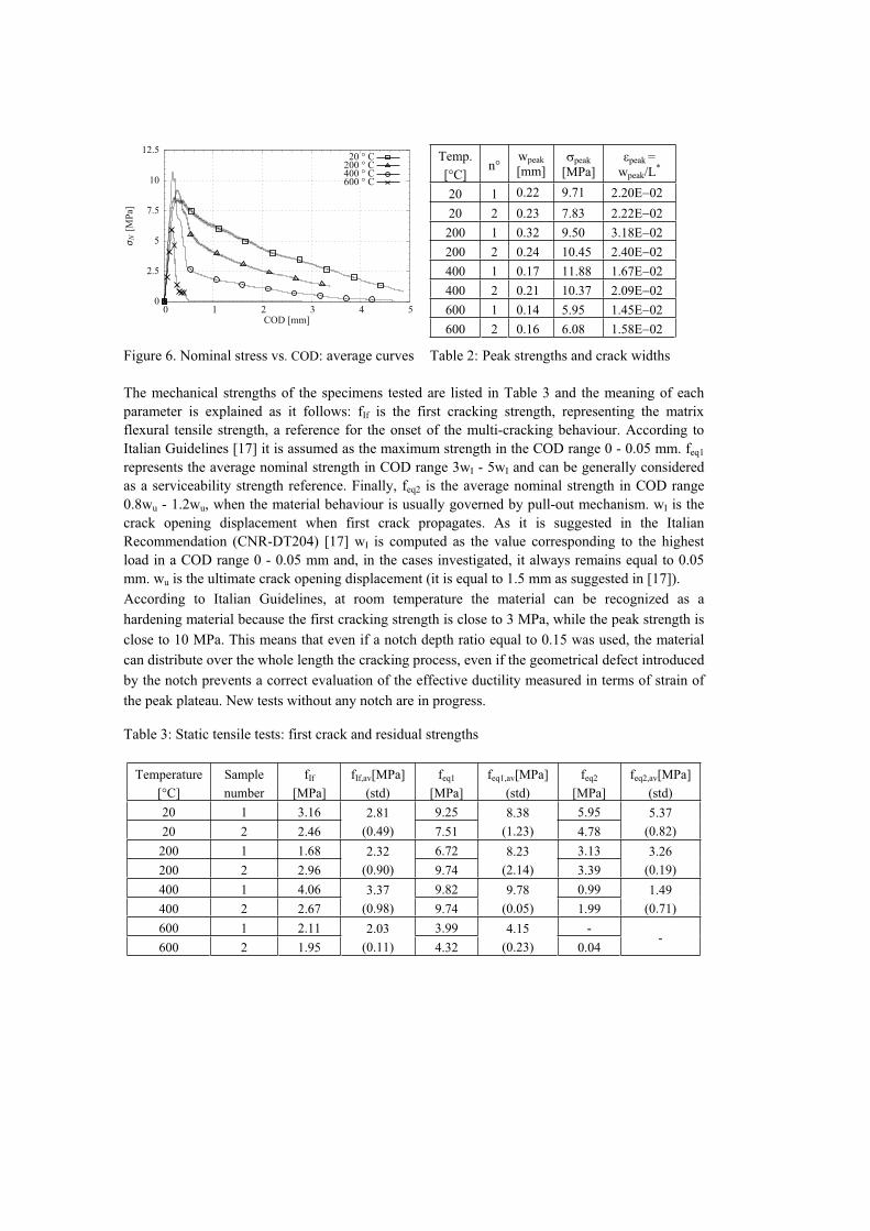
The results of tensile tests are shown in Figures 4a, 4b, 5a and 5b respectively for temperature 20,
200, 400 and 600 °C in terms of nominal stress ( N) versus crack opening displacement (COD),
while Figure 6 shows the comparison of average curves. Besides in Figures 4 and 5 a detail of the
peaks zone are plotted in order to highlight the first linear elastic and post peak behaviour close to
the peak. Peak strengths and corresponding crack opening displacements are listed in Table 2; the
values of peak strains reported in Table 2 were calculated as it follows:
peak= wpeak / L* (1)
where L* (=10 mm) represents the equivalent specimen length. According to this assumption the
cavity depth of the platens (5 mm for each side, where samples were glued, Figure 3) can be
approximately considered as a rigid zone.
It is interesting to observe how steel fibres are able to favour stable propagation at room
temperature up to a strain, computed according to Equation (1), of about 4%. The pre-peak
behaviour is well described by a parabola-rectangular model, where the plateau is very close to a
value of about 2%. By increasing the temperature, the peak strength does not significantly change
up to a maximum temperature of 400°C and this is very interesting. The elastic modulus decreases
with temperature growth in the pre-peak region, where a multi-crack propagation takes place. The
constant stress plateau becomes weakly softening at 200°C; even though up to 400°C the peak
strength remains very close to 2%. At 600°C the behaviour is significantly changed by a peak
strength reduction of about 40% a significant elastic modulus decrease, but the material can exhibit
a stress plateau up to about 2% of strain.
Figure 1. Thermal cycles.
0 20 40 60 80
T im e [h ]
0
200
400
600
T [ C ]600 C
400 C
200 C
Cooling at room conditions

Figure 2. Test set-up Figure 3. Press platens and glued specimen
a) b)
Figure 4. Nominal stress vs COD: (a) room temperature tests; (b) tests on samples exposed to a
thermal cycle up to 200 °C.
a) b)
Figure 5. Nominal stress vs COD: tests on samples exposed to a thermal cycle up to:
(a) 400 °C; (b) 600 °C.
averagesample 2sample 1
COD [mm]
σN
[MP
a]
543210
12.5
10
7.5
5
2.5
0
0.40.30.20.10
12.5
10
7.5
5
2.5
0
averagesample 2sample 1
COD [mm]
σN
[MP
a]
543210
12.5
10
7.5
5
2.5
0
0.40.30.20.10
12.5
10
7.5
5
2.5
0
averagesample 2sample 1
COD [mm]
σN
[MP
a]
543210
12.5
10
7.5
5
2.5
0
0.40.30.20.10
12.5
10
7.5
5
2.5
0
averagesample 2sample 1
COD [mm]
σN
[MP
a]
1.51.2510.750.50.250
12.5
10
7.5
5
2.5
0
0.40.30.20.10
12.5
10
7.5
5
2.5
0
L*
A A
Cavity
Section A-A
Press platen
Temp.
[°C]n°
wpeak
[mm]peak
[MPa]peak =
wpeak/L*
20 1 0.22 9.71 2.20
20 2 0.23 7.83 2.22E 02
200 1 0.32 9.50 3.18E
200 2 0.24 10.45 2.40E
400 1 0.17 11.88 1.67E
400 2 0.21 10.37 2.09E
600 1 0.14 5.95 1.45E
600 2 0.16 6.08 1.58E
Figure 6. Nominal stress vs. COD: average curves Table 2: Peak strengths and crack widths
The mechanical strengths of the specimens tested are listed in Table 3 and the meaning of each
parameter is explained as it follows: fIf is the first cracking strength, representing the matrix
flexural tensile strength, a reference for the onset of the multi-cracking behaviour. According to
Italian Guidelines [17] it is assumed as the maximum strength in the COD range 0 - 0.05 mm. feq1
represents the average nominal strength in COD range 3wI - 5wI and can be generally considered
as a serviceability strength reference. Finally, feq2 is the average nominal strength in COD range
0.8wu - 1.2wu, when the material behaviour is usually governed by pull-out mechanism. wI is the
crack opening displacement when first crack propagates. As it is suggested in the Italian
Recommendation (CNR-DT204) [17] wI is computed as the value corresponding to the highest
load in a COD range 0 - 0.05 mm and, in the cases investigated, it always remains equal to 0.05
mm. wu is the ultimate crack opening displacement (it is equal to 1.5 mm as suggested in [17]).
According to Italian Guidelines, at room temperature the material can be recognized as a
hardening material because the first cracking strength is close to 3 MPa, while the peak strength is
close to 10 MPa. This means that even if a notch depth ratio equal to 0.15 was used, the material
can distribute over the whole length the cracking process, even if the geometrical defect introduced
by the notch prevents a correct evaluation of the effective ductility measured in terms of strain of
the peak plateau. New tests without any notch are in progress.
Table 3: Static tensile tests: first crack and residual strengths
Temperature
[°C]
Sample
number
fIf
[MPa]
fIf,av[MPa]
(std)
feq1
[MPa]
feq1,av[MPa]
(std)
feq2
[MPa]
feq2,av[MPa]
(std)
20 1 3.16 2.81
(0.49)
9.25 8.38
(1.23)
5.95 5.37
(0.82) 20 2 2.46 7.51 4.78
200 1 1.68 2.32
(0.90)
6.72 8.23
(2.14)
3.13 3.26
(0.19) 200 2 2.96 9.74 3.39
400 1 4.06 3.37
(0.98)
9.82 9.78
(0.05)
0.99 1.49
(0.71) 400 2 2.67 9.74 1.99
600 1 2.11 2.03
(0.11)
3.99 4.15
(0.23)
--
600 2 1.95 4.32 0.04
600 ° C400 ° C200 ° C20 ° C
COD [mm]
σN
[MP
a]
543210
12.5
10
7.5
5
2.5
0

4.0 Set-up for high strain rate test
In the research program, different Modified Hopkinson Bars (MHB) have been used. These MHBs
are installed in the DynaMat laboratory of the University of Applied Sciences of Southern
Switzerland (SUPSI) of Lugano (Fig. 7). In particular the results described in this paper have been
obtained with a MHB for specimen of 20mm in diameter.
Figure 7. DynaMat laboratory: set-up for the high strain-rate tensile tests on specimen Ø=20mm
The MHB consists of two circular aluminum bars, called input and output bars, having a length of
3 m and 6m, respectively with a diameter of 20 mm to which the HPFRCC specimen is glued
using a bi-component epoxy resin. The input bar is connected with a high strength steel pretension
bar used as pulse generator. A test with the MHB is performed as follows:
a) first a hydraulic actuator, of maximum loading capacity of 600 kN, is pulling the pretension
high strength steel bar having a length of 6 m and a diameter of 12 mm; the pretension stored in
this bar is resisted by the blocking device (see Figure 7)
b) second operation is the rupture of the fragile bolt in the blocking device which gives rise to a
tensile mechanical pulse of 2.4 ms duration with linear loading rate during the rise time,
propagating along the input and output bars bringing to fracture the specimen. The pulse
propagates along the input bar with the velocity C0 of the elastic wave with its shape remaining
constant. When the incident pulse ( I) reaches the HPFRCC specimen, part of it ( R) is reflected by
the specimen whereas another part ( T) passes through the specimen propagating into the output
bar as shown in Figure 8. The relative amplitudes of the incident, reflected and transmitted pulses,
depend on the mechanical properties of the specimen. Strain-gauges glued on the input and output

0
0.0001
0.0002
0.0003
0.0004
0.0005
0 0.0005 0.001 0.0015 0.002
raw signals
inputoutput
str
ain
in
in
pu
t a
nd
ou
tpu
t b
ars
[m
/m]
time [s]
incid
en
t p
uls
e
reflecte
d p
uls
etr
ansm
itte
d p
uls
e
0
5
10
15
20
25
30
0
50
100
150
200
250
300
0 0.0002 0.0004 0.0006 0.0008 0.001
stress strain-rate
str
es
s [
MP
a]
stra
in ra
te [s
-1]
time [s]
Figure 8. Signals measured on the input and output bar
versus time curves of HPFRCC.
Figure 9. Stress and strain-rate vs. time
curves of HPFRCC (strain-rate=138 s-1).
bars of the device are used for the measurement of the elastic deformation (as a function of time)
created on both half-bars by the incident/reflected and transmitted pulses, respectively.
In Figure 8 the raw signals measured on the input and output bars are shown. It can be observed
the clean resolution of incident, reflected and transmitted pulses, the sharp rise time of the incident
pulse of the order of 30 s, and the nearby constant amplitude of the incident pulse. Moreover
during the fracture process the specimen is subjected to the load equilibrium, because the signals
( I+ R) and T are equal. In fact, naming F1 the load in the specimen-input bar interface and F2 the
load in the specimen-output interface they are defined as: F1(t) = A0 E0 ( I+ R) and F2(t) = A0 E0 T
By using the theory of the elastic wave propagation in bars, and the well substantiated assumption
of specimen equilibrium attainment, the stress and strain in the specimen as well as the history of
the crack opening displacement (COD) and the strain-rate can be calculated [7, 8, 9, 13, 14]:
tA
AEt
T
0
0 (2)
dttL
2t
t
0R
0C (3)
dtt2tCODt
0R0C (4)
tL
2t R
0C (5)
where: E0 is the elastic modulus of the bars; A0 their cross-sectional area; A is the specimen cross
section area; L is the specimen gauge length; C0 is the sound velocity of the bar material; t is time.
In the case of these HPFRCCs strain-rate can be calculated as for metallic or ductile materials,
where the plastic zone is well defined, the stain-rate is obtained as an average of the strain-rate
value during the abovementioned zone. Using the equation (4) and observing Figure 9 the strain
rate can be easily obtained: in the case it is 138 s-1.
5.0 Preliminary results at high strain rate
The high strain rate results obtained on HPFRCC exposed to 20, 200, 400 and 600°C are reported
in Table 4.

Table 4: High strain rate results on HPFRCC
Sample identification Thermally
exposed at
ft
[MPa]
ft,av
[MPa]
CODu
[mm]
CODu,av
[mm]
Gf
[J/m²]
Gf,av
[J/m²]
SFRCC_20_3_n2 20.46 0.038 34017
SFRCC_20_3_n3 20°C 22.28 24.96±2.3 0.032 0.031±
0.00731123
28861±
4911
SFRCC_20_3_n4 24.96 0.024 24442
SFRCC_200_3_n2 26.65 0.022 8148
SFRCC_200_3_n3 200°C 26.72 26.08±1.0 0.035 0.026±
0.0087700
10348±
4205
SFRCC_200_3_n7 24.88 0.022 15197
SFRCC_400_2_n1 27.86 0.057 2206
SFRCC_400_2_n2 400°C 27.22 25.28±3.9 0.019 0.033±
0.0201342
1308±
914
SFRCC_400_2_n4 20.77 0.025 378
SFRCC_600_3_n1 31.13 0.017 1002
SFRCC_600_3_n2 600°C 32.24 32.49±1.5 0.026 0.018±
0.008718
736±
257
SFRCC_600_3_n5 34.09 0.011 489
In Figure 10 are shown the stress versus time curves of the HPFRCC specimen tested with the
same high strain rate. It can be observed as the behavior change in function of the exposition to
high temperature. Analyzing the data Table 4 two facts can put in evidence: at this velocity the
peak increases with the exposition to high temperature as well as the post-peak strength decrease
till to disappear for higher temperature.
By observing the fracture surface of the specimen it is evident as the failure has changed. In Figure
10, in fact the comparison between the reference specimen cured at room temperature and that
exposed to 600°C is represented. In the first, the hole in the specimen that demonstrates the pullout
process of the fibers is while in the second one all the fibers are collapsed. This means that, during
the exposition, fibres became more brittle due to thermal damage.
6.0 Conclusions
The results experimentally obtained in uniaxial tension allow us to evidence the following
remarks:
- at low strain rates, the material is strain hardening at room temperature; high temperature
exposure up to 400°C does not decrease the peak strength, weakly decreases the Elastic
modulus and the homogeneous ductility before the localization in a single crack and the
post-peak fracture energy progressively decreases; at 600°C a peak strength
- at high strain rate, the dynamic factor related to peak strength is increased by high

temperature exposure, passing from about 2.5 up to 400°C to more than 5 at 600°C at a
strain rate close 140s-1. On the contrary, the toughness is progressively reduced.
- The use of notched specimens could have significantly affected the ductility of the tests
for both high and low strain rates. New tests on un-notched specimens made of the same
material are in progress.
0
5
10
15
20
25
30
35
0 0.0002 0.0004 0.0006 0.0008 0.001
N [
MP
a]
time [s]
HPFRCC as received (20°C)
0
5
10
15
20
25
30
35
0 0.0002 0.0004 0.0006 0.0008 0.001
N [
MP
a]
time [s]
HPFRCC exposed to 200°C
0
5
10
15
20
25
30
35
0 0.0002 0.0004 0.0006 0.0008 0.001
N [
MP
a]
time [s]
HPFRCC exposed to 400°C
0
5
10
15
20
25
30
35
0 0.0002 0.0004 0.0006 0.0008 0.001
N [
MP
a]
time [s]
HPFRCC exposed to 600°C
Figure 10. Stress versus time curves of HPFRCC with different thermal damage.
7.0 Acknowledgements
The Authors are grateful to Ing. Matteo Dotta, Ing. Daniele Forni and Mr. Samuel Antonietti of the
SUPSI University for their precious collaboration in the execution of the laboratory tests. The
research was financially supported by the INTERREG IVA Program (Cross-Border Territorial
Cooperation Program for Italy and Switzerland): project ACCIDENT.

8.0 References
1. Ahmad, A., di Prisco, M., Meyer, C., Plizzari, G.A. and Shah, S. (Eds.), “Fiber Reinforced
Concrete: From theory to practice” Starrylink Editrice, 2004.
2. Bindiganavile, V. and Banthia, N.: “Impact and blast resistance of fiber reinforced concrete,”
Draft report circulated in ACI 544 Technical Commission, 2007.
3. Bindiganavile, V.; Banthia, N. and Aarup, B. 2002.” Impact response of ultra-high strength fiber
reinforced cement composite,” ACI Materials Journal, 99 (6): 543-548.
4. Pacios, A., Ouyang, C.and Shah, S. P. 1995. “Rate effect on interfacial response between fibers
and matrix,” Materials and Structures, RILEM, 28: 83-91.
5. McVay, M. K.: “Spall damage of concrete structures,” Technical Report SL-88-22,Waterways
Experiment, Corps of Eng., Vicksbury, MS, 1998.
6. di Prisco, M., Felicetti, R., Lamperti, M., Menotti, G., “On size effect in tension of SFRC thin
plates,” Fracture Mechanics of Concrete Structures, V.C. Li C.K.Y. Leung, K.J. Willam, S.L.
Billington, (Eds.), 2, B.L.Schmick and A.D.Pollington, USA, 2004, pp. 1075-1082.
7. Albertini, C. and Montagnani, M., “Testing techniques based on the split Hopkinson bar,” Int.
Conf. on “The mechanical properties at high strain-rates”, Oxford University, Institute of Physics
Conference Series, 21, 1974,pp. 22-32.
8. Albertini, C., Cadoni, E. and Labibes, K.. 1999. “Study of the mechanical properties of plain
concrete under dynamic loading,” Experimental Mechanics, 39 (2): 137-141.
9. Cadoni, E., Solomos, G. and Albertini, C. 2009. “Mechanical characterization of concrete in
tension and compression at high strain-rate using a modified Hopkinson bar”, Magazine of
Concrete Research, 61(3): 221-230.
10. Asprone, D., Cadoni, E. and Prota, A. 2009. “Experimental Analysis on Tensile Dynamic
Behavior of Existing Concrete under High Strain Rates”, ACI Structural Journal, 106(1): 106-113.
11. Cadoni, E., Caverzan, A. and di Prisco, M. “Dynamic behaviour of HPFR cementitious
composites” in Ultra High Performance Concrete, eds. Fehling, Schmidt and Stürwald, Kassel,
Heft 10, Structural Materials and Engineering Series, Kassel University Press, 2008, , pp. 743-750.
12. Ferrara L., Nilufer O. and di Prisco M. 2009. “High mechanical performance of fiber
reinforced cementitious composites: the role of “casting-flow induced” fiber orientation”
submitted to Materials and Structures.
13. Cadoni, E., Meda, A. and Plizzari, G.A., “Rate sensitivity of HPFRCC under tensile loading:
from quasi-static to high strain rates”, Fibre Reinforced Concrete Design and Applications, Editor
R. Gettu, Rilem Pro60, Chennai, India, 2008,pp.441-450.
14. Cadoni, E., Meda, A. and Plizzari, G.A. “Tensile behavior of FRC under high strain-rate”, in
print Materials and Structures.
15. Cadoni, E., Dotta, M., Meda, A. and Plizzari, G.A. “Analysis of Fiber Reinforced Concrete
under impact loading,” Proeedings of 1st workshop PROTECT 2007, Whistler, Canada, 2007.
16. Caverzan, A., Colombo, M. and di Prisco, M., “High Performance Steel Fibre Reinforced
Concrete: Residual Behaviour at high Temperature, “ Proceedings of 2nd workshop PROTECT
2009, Hayama, Japan, 2009, on press.
17. CNR-DT 204: Instruction for design, execution and control of fibre reinforced concrete
structures, Italian Standards, 2006.