introduction of rgtpp the plant is located near ramgarh town of district jaisalmer in rajasthan. ...
TRANSCRIPT

PRESENTATION ON WATER COOLING TOWER

INTRODUCTION OF RGTPP
The Plant is Located near Ramgarh Town of District Jaisalmer in Rajasthan.The Plant is 60 Km from Jaisalmer. The installed capacity of the first stage is 110 MW.The GAIL Pipeline is approximately 35 km from the Ramgarh Site, from where a tap offline is also taken.

WATER COOLING TOWER
Cooling tower is a heat rejection device, which extracts water heat to the atmosphere though the cooling of a water stream to a lower temperature.
The generic term "cooling tower" is used to describe both direct (open circuit) and indirect (closed circuit) heat rejection equipment.


SPECIFICATION OF LOADING & RCC MATERIAL
The specifications covers general requirements of materials, design, construction and testing of RCC works involved in the construction of RCC induced draft cooling tower.
Loading Concrete works Reinforcing steelStructural steelPainting for concrete surfaces

Loading
•Wind loads shall be considered as per IS:.875(part-3)
•Earthquake loads shall be considered as per IS:1893 duly considering the type of soil and foundation system
•Dead load shall be considered as per IS:875(part-2).

Concrete Works
• Cement used shall be OPC complying with IS:8112
• Minimum grade of concrete for various structural components shall be M 25.
• Minimum cement content per/cum of concrete shall be as specified in IS:456.
• Minimum cement content shall be used as per IS:456.
• Material design, construction and workmanship in general shall conform to IS:456 and IS:3370.
• For pre stressed concrete works, design, construction and workmanship shall be in accordance with IS:1343

Reinforcing steel
Reinforcement bars shall be either mild steel conforming to IS:432 or high yield strength reinforced bars conforming to IS:1786
Steel wires for pressurising shall conform to IS:1785(part 1&2) minimum diameter of steel wire of 4mm

Structural steel
Steel used shall conform to IS:2062 grade A or B as specified.
The minimum coating of zinc shall be 500gm/m^2 and shall comply with requirements of IS:2629 and IS:2633.
Galvanised surfaces shall be further protected by providing two coats of bituminous coating conforming to IS:1962 after applying etching primer coat as per IS:5666.

Painting for concrete surfaces
Water proof bituminous paint conforming to IS:9862 shall be provided to concrete surfaces .
The preparation of concrete surface for painting shall conform to IS:2395(part-1).
Painting shall consist off one coat of primer conforming to IS:9862 and two coats of bituminous painting conforming to IS:3384

CONSTRUCTION OF WATER COOLING TOWER
1. EXCAVATION2. PLAIN CEMENT CONCRETE3. REINFORCEMENT FOR RAFT4. RAFT CASTING5. COLUMNS6. BEAMS & WALLS7. SLABS8. CURING

1.EXCAVATION
Excavation is done for dimensions of 20 mx12mx2m.The earthwork so excavated is removed from the site with the help of JCB & truck.
2.PLAIN CEMENT CONCRETE
PCC is done above the compacted earth surface using concrete material of grade M5.
The ratio of materials used in PCC is 1:4:8.
The PCC is done before the placement of reinforcement for raft foundation so as to prevent the rusting of the reinforcement by oxidation process which takes place in presence of moisture of earth surface & the air.


3.REINFORCEMENT FOR RAFT

4.RAFT CASTING
Concrete of grade M10 is used for casting of the raft foundation.The ratio of material used in concrete for raft casting is 1:3:6

STAGES OF RAFT CASTING
I. Batching

II. Mixing

III. Transportation & placing

IV. CompactionCompaction of concrete in raft foundation is done by needle vibrator.

It consist of power unit, flexible shaft & needle.
It is used for removal of air voids in concrete paste.
Frequency = 12000 cycles of vibrations/minute
Needle dia. =20mm to 75mm.
Length of flexible shaft= 25 to 90 cm.

5.COLUMNSFormwork is used for erection of the material which is used for construction of columns & beams of the water cooling towerFormwork vibrator is used for compaction of the concrete columns

6.BEAMS & WALLS
Beams are casted at a height of 3m from the raft casting with the spacing of 30cm along the width of cooling tower.
A gap of 1.2m is left vacant above the layer of the beam and beneath the stone wall for placing the 3 layer of fill pack material.
Stone wall is constructed above the layer of beams separating each of the adjacent cell of the cooling tower(7 in no.).

Above walls separating each shell of cooling tower a layer of beams is provided with a spacing of 30cm along the width of cooling tower.
A layer of drift eliminator is placed above this layer of beam within the spacing's created by the layer of beams.
Stone walls are constructed immediately above the second layer of beams .


7.SLABS
One way slab is constructed above the walls of the shells with openings left for casting of the fan cylinder.

8.CURINGAfter concrete is placed, a satisfactory moisture content and temperature must be maintained, a process called curing. Adequate curing is vital to quality concrete.
Curing the concrete aids the chemical reaction called hydration. Most freshly mixed concrete contains considerably more water than is required for complete hydration of the cement; however, any appreciable loss of water by evaporation or otherwise will delay or prevent hydration.


SHELL OF COOLING TOWER

COMPONENTS OF WATER COOLING TOWER
1. Cold Water Basin2. Fill Media3. Plastic Pipes With Nozzles4. Drift Eliminators5. Erection Of Fans.

1.COLD WATER BASIN

• The basin floor of each compartment shall be sloped towards a collecting sump for effectively draining the water to permit desilting / desludging.
• Water shall be drained from the sump into a drain chamber outside the basin by CI drain pipe embedded below the basin floor.
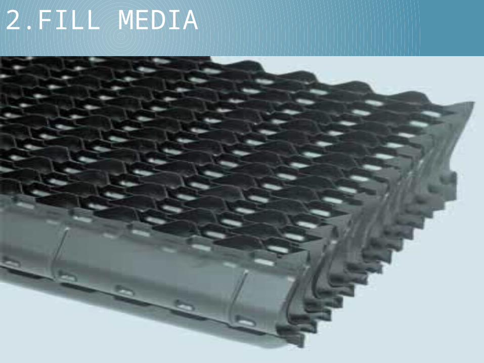
2.FILL MEDIA

• Plastics are widely used for fill, including PVC, polypropylene, and other polymers.
• Three layers of fill media is used in each shell with a total of 1308 pieces, 436 per layer.
• Plastics are glued together with solgum cement(16 pcs. Of PVC sheets are glued to form 1 piece of fill media)
• Fill pack size 300mm x 600mm (42 pcs. In top layer)1220mm x 300mm(394 pcs. In top layer)
600mm x600mm (middle layer)1200mm x 600mm (bottom layer)

3.PLASTIC PIPES WITH NOZZLES•18 pipes are arranged in each shell of cooling tower with 9 pipes on each side of the channel carrying the hot water brought from the power plant through large pipes .

4.DRIFT ELIMINATORS•These capture water droplets entrapped in the air stream that otherwise would be lost to the atmosphere Air after passing through the fill media is moving upwards with air velocity sufficiently large to provide an upward thrust for small water droplets in the cooling tower.

5.ERECTION OF FAN
Gear box Shaft Electric motor
