introduction of new ground investigation guideline ... shelter basalt dyke up to 120 m long 20 gi...
TRANSCRIPT

Introduction of New Ground Investigation GuidelineIntroduction of New Ground Investigation GuidelineHorizontal Directional Coring (HDC)Horizontal Directional Coring (HDC)
AGS(HK) Technical SeminarAGS(HK) Technical Seminar14 August 201214 August 2012
ByByBruce CunninghamBruce Cunningham
& Janice Tam& Janice Tam
The image cannot be displayed. Your computer may not have enough memory to open the image, or the image may have been corrupted. Restart your computer, and then open the file again. If the red x still appears, you may have to delete the image and then insert it again.
The image cannot be displayed. Your computer may not have enough memory to open the image, or the image may have been corrupted. Restart your computer, and then open the file again. If the red x still appears, you may have to delete the image and then insert it again.
G4.9 – Horizontal Directional Coringhttp://www.ags-hk.org/
AGS (HK) Ground Investigation Guideline (2012)
2
3
Part ONEUse of HDC to Identify Problematic Ground
in Tunnel ProjectsBy Janice Tam
1. Introduction
2. Considerations for HDC Planning
3. HDC for Geological Model Assessment
1. Introduction
Part ONE

5
What is Horizontal Directional Coring?
Ground Investigation Technique developed in Norway, in late 80’s.
Steerable coring along the planned trajectory.
Provide continuous core sample.
Used in petroleum & mineral explorations and tunnel project.
Steerable Coring along Tunnel AlignmentSide-tracking Coring
6
Why uses HDC in Tunnel Projects?
Minimize the risk of unforeseen tunneling conditions.
Extent of problematic rock.
Natural groundwater inflow measurement.
Continuous core near the tunnel level gives a lot more information for design and for the tenderers to price than can be obtained from vertical boreholes at regular spacing.
HDC launching point can be positioned on land for core sampling seawards and under water.
Improve Ground ModelFor Reliable Assessment
Reduce Geological &Construction Risks
Vert. BH
Vert. BH
Proposed Tunnel
2. Considerations for HDC Planning
Part ONE
8
When & Where should HDC be used?
Confirmed tunnel alignment.
Preliminary Geological Model.
Target the Identified key areas of Geotechnical Hazards / Problematic Ground.

9
Specification of HDC Technique
Max. bending angle:
9 deg/30 m (R=180 m).
Max. core-run:
3 m in deviated section.
3 or 6 m in straight section.
Core diameter:
DV size (31.5 mm) in deviated section.
NQ size (47 mm) in straight section.
Hole diameter:
Typically in N-size (76 mm).
DV
NQ
Steerable Barrel
Primary steerable coring system was designed for directional coring in competent rock.
10
Typical Working Areas
HDC for ~1200 mWorks Area 25 m long & 20 m wide
HDC for ~600 mWorks Area 15 m long & 10 m wide
11
Proposed HDC Trajectory
Designer should provide the proposed trajectory to the coring specialists e.g. control points of coordinates & level.
Tolerance Envelope
Smooth launching & curvature to get optimum coring length.
As-built alignment of HDCProposed trajectory of HDCTolerance envelope
As-built corehole trajectory for recent completed Hong Kong tunnel project
12
Proposed HDC Trajectory
DV & NQ Coring within the Designed Envelope
Proposed trajectory of HDCControl PointTolerance envelopeDV coring & steering with curvatureNQ coring in straight section

13
Coring Duration
Coring length
Tolerance envelope
Field test quantity
Approx. Coring Length
Tolerance Envelope (Dist. from trajectory)
Approx. Coring Duration (Months) Remarks
300 m 2 m 2 Field tests
600 m 5 m 5 Field tests
1200 m 5 m 10 Field tests
1200 m 8 m 6 No field test
Coring duration of HDC referring to the recent completed Hong Kong projects
3. HDC for Geological Model Assessment
Part ONE
15
What is Geological Model?
Examination of regional & local geological conditionsCharacterizes the site focusing on
Geological feature
Geomorphological feature
Hydrogeological feature
Characteristics relevant to the engineering project
To anticipate variations in material properties and boundaries in 3D.
16
Identify Problematic Ground for HATS 2A Design
HD05 HD03a
HD03
HD02
HD01
HD04

17
HDC passing through inferred Fault Zone
Causeway Bay Typhoon Shelter
HD03a
HD03
18
What we found in Tai Tam Fault?
NRNR
Altered & highly chloritized, medium to
coarse grained GRANITE
Strong, dark grey, striped white, slightly
decomposed BASALT…..
Fault Breccia Fault
BrecciaSheared Granite
NR
NR
19
HDC passing through Tai Tam Fault
Granite with Basalt Dykes & Microfracturedwithin the Tai Tam Fault
Zone
Altered & highly chloritized, medium to coarse grained
GRANITE
Shear Zones
Causeway Bay Typhoon Shelter
Basalt Dyke up to 120 m long
20
GI Data for Geological Model Assessment
HD03aHD03a
Grade III-II, locally NR, locally highly fractured, altered
Granite
Grade III-II, highly altered & chloritized Granite, with local
shear zones, quartz vein and micro-
fractures
Grade II Basalt Dyke, 120 m apparent width with sheared III-IV
Grade III-II, locally sheared Basalt Dyke
Tai Tam Fault ZoneWith Consistent high
Lugeon Test Value
RockheadRockhead
•Vertical & Inclined BH –Rockhead Level
•Continuous core sample of HDC –Geology along tunnel alignment
•Lugeon Tests –Rock Permeability
•Water Inflow Tests –Water Ingress Prediction
•Lab Tests -Rock Mass Quality around tunnel level
TunnelTunnel

Potential Hydrothermal Alteration Zone along TKO-LTT
21
Granite
Tuff
HydrothermallyAltered Rocks
TKO Line
Black Hills Tunnel Incident
Altered rock in the TKO Line.Across MTRC Black Hills tunnels at about 200 m deep.Encountered unexpectedly, caused collapse & programme delay of the TKO Line.GI indicated a RH depression in the area of veins on geological map.
Information from Vertical Borehole
22
Granite
Tuff & Granite Contactat +18mPD
Tuff & Granite Contact at +69mPD
Greisenised Granite Tuff
BH offset 70mTuff & Granite Contact
at +3mPD
HDC
Information from HDC
23
HDC
GreisenisedGranite Tuff
HDCTuff & Granite Contactat about 555m depth
(+33mPD)
Granite
Tuff
Greisenised Granite& Pegmatite
24
Summary
Key of Geological Model Assessment•Estimation of Rock mass quality•Determination of rock permeability•Prediction of groundwater ingress
Engineering Parameters used for the Assessment
•Rock Types & decomposition grades•Identification of Problematic Ground•Rockhead Level•Rock mass classification (Q-value)•Rock permeability (Lugeon Value)•Lab test results
Estimation of Tunnel Construction Performance•Rates of production•Temporary support requirements•Measures to reduce inflow of groundwater
More Detailed Ground Model such as adopting the HDC Technique
with Field tests in HDC
More Reliable Assessment &Reduced Construction &
Geological Risks

25
Part TwoProject References and HDC Technique
By Bruce Cunningham
1. Project References
2. HDC Technique
3. Typical Field Tests in HDC
4. Tunnelling Though Fault Zone
1. Project References
Part TWO
27
Route 8 – Eagle’s Nest Tunnel
Road Tunnel at Construction Stage
HDD/NP/1, March 04 to Sept. 04
HDD/SP/1, Dec. 04 to Jan. 04
Tolerance envelope of 8 m radius
HDD/SP/1(550 m)
HDD/NP/1(1152 m)
28
Route 8 – Eagle’s Nest Tunnel
HDC Setup at North Portal
Northbound Tunnel
Working area of HDC
Southbound Tunnel

29
Route 8 – Eagle’s Nest TunnelSite Formation at South Portal
Setting up HDC at the rear of South Portal
HDC at South Portal
Route 8 – Eagle’s Nest Tunnel
30
HDD/SP/1HDD/SP/1
31
Po Shan Road Drainage Tunnel
Drainage Tunnel Design & Construction2 nos. of HDCNov. 05 to Jan. 06Tolerance envelope of 2 m radius
PS-HDC/01252 m
PS-HDC/02310 m
Tunnel Alignment
HDC along Tunnels
32
Po Shan Road Drainage Tunnel
Site Setup of HDC
Working Platform for PSWorking Platform for PS--HDC01 (252 m)HDC01 (252 m)
Coring rig for PSCoring rig for PS--HDC02 (310 m)HDC02 (310 m)

33
Ap Lei Chau
Wa FuAberdeen
Sandy Bay
Cyberport
North Point
Stonecutters Island
Wan Chai East
Central
Sai Ying Pun
HD03a(795m)
HD05(700m)
HD04(1085m)
HD02(610m)
HD01(1250m)
HD03(655m)
Trajectory of HDC
HATS 2A – the Pioneer Project in Hong Kong for:First sub-sea level application with HDC.Deepest core (reaching target zone at -160mPD) with HDC.Longest continuous samples below Victoria Harbour (i.e. over 1000m from HD01 & 04).In-situ Groundwater Inflow Measurement in sub-horizontal hole under sub-sea condition.
Harbour Area Treatment Scheme Stage 2A
34
Harbour Area Treatment Scheme Stage 2A
Details of HDC in HATS 2A
HDC Duration LengthLevel of
Horizontal section
Nos. of Inflow Test
Nos. of Packer
Test
Nos. of
IP Test
HD01 10 months 1250 m ~140 mPD 10 13 20
HD02 5 months 610 m ~145 mPD 4 4 4
HD03 6 months 655 m ~145 mPD 6 12 12
HD03a 5 months 795 m ~150 mPD 5 10 0
HD04 8 months 1085 m ~135 mPD 0 8 24
HD05 5 months 700 m ~135 mPD 5 9 4
35
Harbour Area Treatment Scheme Stage 2A
HATS 2A – Site Setup of HDC
HDC02 at Central (610 m)HDC02 at Central (610 m)
HDC04 at Stonecutters Island (1085 m)HDC04 at Stonecutters Island (1085 m)
HDC01 at HDC01 at SaiSai Ying Pun(1250 m)Ying Pun(1250 m)
HDC03a at Cargo Area (795 m)HDC03a at Cargo Area (795 m)
HDC03 at Wai HDC03 at Wai ChaiChai East (655 m)East (655 m)
HDC05 at Kennedy Town (700 m)HDC05 at Kennedy Town (700 m)
Harbour Area Treatment Scheme Stage 2A
36

Harbour Area Treatment Scheme Stage 2A
37
Harbour Area Treatment Scheme Stage 2A
38
Harbour Area Treatment Scheme Stage 2A
39
Liantang / Heung Yuen Wai Boundary Control Point
40
Sheung Sheung ShuiShui
NE NTNE NT
BCPBCP
FanlingFanling

Liantang / Heung Yuen Wai Boundary Control Point
41
HDC1:HDC1:1,200m1,200m
HDC2: HDC2: 950m950m
HDC3: HDC3: 1,000m1,000m
HDC4: HDC4: 530m530m
HDC5: HDC5: 400m400m
HDC6: HDC6: 470m470m
HDC LayoutHDC LayoutGeologyGeologyTai Mo Shan Formation
Shing Mun Formation
• Drilling of HDC5 & 6 completed. • Others in progress.• HDC5 completed in 2 months.• HDC6 completed in 2.5 months.• Tolerance Envelope of 8 m radius.
HDC3 – Proposed length 1000 m
Tolerance envelope of 8 m radius
Liantang / Heung Yuen Wai Boundary Control Point
42
Tseung Kwan O – Lam Tin Tunnel
43
HDC: HDC: 946 m946 m
• Drilling of HDC completed in June 12.• Testing in progress.• Duration: Approx. 6 months.• Tolerance Envelope: 5 m radius.
HDC of 945 m
Tolerance envelope of 5m radius
Tseung Kwan O – Lam Tin Tunnel
44

2. HDC Technique
Part TWO
46
Coring Procedure of HDC
Set toolface -orientation and Core with Steerable Coring Tool.
Connect the innertubeand surveytool.
Read orientation and inclination.
Survey through out the bit for azimuth reading.
Peewee Tool
Extension Rod
CoringSurvey during Coring
Corhole Survey
47
Coring Procedure of HDC
• Procedure of HDC– Planning
• Trajectory along the tunnel horizontal alignment • Targeting to pass through the expected fault zones
– Coring• Steerable within planned trajectory.
– Surveying• Regular surveys to ensure the HDC remained within the planned
trajectory envelope.
Steerable Coring Barrel
Borehole surveying tool
HDC Specialist
48

49
HDC Steerable Barrel• The 3 main components of a steerable barrel
– Locking Piston – to provide a locked position for the barrel.– Packer Assembly – to maintain the toolface position during the streering
process.– Adjustable Eccentric Housing – to adjust the bending angle.
Toolface /Rolling Angle
Dogleg / Bending Angle
50
2. HDC Steerable Barrel
PACKER
CORING BIT
ADJUSTABLE ECCENTRIC HOUSING
LOCKING PIN
51
Borehole Surveying Tool
• Corehole Surveying Tool – PeeWee EMS– A miniature electronic multishot that is used
for surveying of borehole profile.– Length of 0.975 m.– Diameter of 30 mm.– To provide orientation of a borehole.
Survey through out the bit for azimuth reading.
Peewee Tool
Extension Rod
Corehole Survey
52
HDC Working Procedure
• HDC Working Procedure in HATS 2A
HARD ROCK
GROUND
A
A
PROPOSED SEWAGE CONVEYANCE TUNNEL
160m
SECTION A-A
CORING RIG
1. INSERT CASING INTO ROCK HEAD2. STEER HDC DOWN AND LEVEL OUT TO TUNNEL HORIZON 3. DRILL OUT HORIZONTAL CORING IN 50m STAGES WITH SPECIALIST
STEERING AND WITH PUMP DOWN PACKER WATER INFLOW TESTING
4. COMPLETE HORIZONTAL CORING THROUGH EXPECTED GEOLOGICAL FEATURE AND TO INVESTIGATE ALONG TUNNEL ALIGNMENT
5. COMPLETE WATER ABSORPTION TESTING WITH DOUBLE PACKER ALONG SELECTED LENGTHS OF HDC BORE
6. GROUT AND BACKFILL HDC BORE

53
HDC Working Procedure
• HDC Working Procedure in HATS 2A
HARD ROCK
GROUND
PROPOSED SEWAGE CONVEYANCE TUNNEL
CORING RIG
54
HDC Working Procedure
• HDC Working Procedure in HATS 2A
HARD ROCK
GROUND
PROPOSED SEWAGE CONVEYANCE TUNNEL
CORING RIG
55
HDC Working Procedure
• HDC Working Procedure in HATS 2A
HARD ROCK
GROUND
PROPOSED SEWAGE CONVEYANCE TUNNEL
CORING RIG
56
HDC Working Procedure
• HDC Working Procedure in HATS 2A
HARD ROCK
GROUND
PROPOSED SEWAGE CONVEYANCE TUNNEL
200m300m400m500m600m700m800m900m1000m1100m1200m
CORING RIG

57
Operation Principle
• Steerable Core Barrel
Hard RockSoft Ground
CORING BIT
ADJUSTABLE ECCENTRIC HOUSINGANTI ROTATION SHOE
LOCKING PIN
58
Operation Principle
• Non-Rotating Outer Barrel
Hard RockSoft GroundCORE BARREL &
INNER DRIVE SHAFT
ECCENTRIC BEARING
1. Non-rotating, stationary outer barrel, by packer inflation, controls the directional setting. It is for maintaining the toolface angle, i.e. the coring orientation.
59
Operation Principle
• Bending Angle
Hard RockSoft Ground
2. Adjustable Eccentric Housing to adjust the bending angle.
60
Operation Principle
• Rotating Inner Barrel
Hard RockSoft Ground
Circulation Pressured Fluid
Fixed
3. Rotating inner barrel comprises an outer casing and an inner tube for core collection.

61
Operation Principle
• Corehole Survey
Hard RockSoft Ground
SURVEY TOOL
4. Borehole profile is surveyed using PeeWee EMS, which is a survey tool of miniature electronic multishot.
62
Working Principles
• Define the trajectory and tolerance
• Straight section -Conventional WirelineCoring
• Curve section - Steerable Coring System
• Navigation by toolface & dogleg angle
• Borehole surveying (i.e. to get the azimuth and inclination)
• Steering System:– Non-rotating outer barrel: Slides in a set toolface while coring– Rotating inner corebarrel: Drive the bit– Non-rotating innertube: Collect the core
Progress Diagram for HD/01 at Sai Ying Pun
63
3. Typical Field Tests in HDC
Part TWO

65
Water Absorption (Lugeon)Test in HDC
• Double Packers for Injection Test– Conventional injection method to determine equivalent rock mass
permeability over relatively short lengths in a horizontal direction.
• Testing Section: 3 m• Perforated Pipe: 15 mm diameter• Packer: 76 mm diameter
HATS Stage 2A
66
Water Absorption (Lugeon)Test in HDC• Double Packers for Injection Test
– Conventional injection method to determine equivalent rock mass permeability over relatively short lengths in a horizontal direction.
Conventional Coring Method Wireline Coring Method
Testing Section : 2 m longPerforated Pipe:20 mm diameter
Testing Section : 2 m longPerforated Pipe:20 mm diameter
Po Shan Road Drainage Tunnel
67
Water Inflow Test by PDPS
• Pump Down Packer System (PDPS)– Sectional inflows in HDC, along the proposed tunnel alignment.– Water quantity seeping naturally from the formation as a result
of pressure difference (i.e. predicting inflow during excavation)– A more realistic hydrogeological model than using the
conventional water absorption test.– To determine an effective grouting approach.
Setup of PDPS in HDC
HATS Stage 2A
68
Water Inflow Test by PDPS
• Testing Procedure
Proposed Proposed TunnelTunnel
HATS Stage 2A
Typical Length of Testing Section: 100 mRanging from 50 m to 120 m.
PS

69
Water Inflow Test by PDPS
• Operation Principle
NQ
FAULT ZONE
ROCK HEAD
PDPS
INNER PACKER OUTER PACKER
• Retrieve the core barrel string and NQ barrel
• Pump down the PDPS along the core barrel strings
70
Water Inflow Test by PDPS
• Operation Principle
NQINNER PACKER OUTER PACKER
INFLATION SHEAR PIN PASSAGE SHEAR PIN
FAULT ZONE
ROCK HEAD
PDPS
PRESSURED FUILD
• Apply hydraulic pressure in stepwise to break the inflation shear pin and inflate the packers
• Further apply pressure to open the passage for test
71
Water Inflow Test by PDPS
CASING PACKER FORMATION PACKER
FAULT ZONE
ROCK HEAD
PDPS
NQ
PACKER
PUMPFLOW METER
PUMP OUT WATER
• Insert the pump to withdraw water from the test section in a steady rate
• Change in flow and pressure at the test section are recorded
72
Water Inflow Test by PDPS
CASING PACKER FORMATION PACKER
FAULT ZONE
ROCK HEAD
PDPS
MECHANICAL PULL-OUT FORCE
NQ
• Slightly pull out the core string barrel to break the deflation shear pin
• Packers deflate and the PDPS is retrieved with overshot

73
Water Inflow Test in Horizontal HolePo Shan Road Drainage Tunnel
Use of:• Stopwatch• Measurement
Jar / Container
74
Water Inflow Test in Horizontal Hole
• Testing Procedure
Typical Length of Testing Section: 20 mRanging from 10 m to 25 m.
Proposed TunnelProposed Tunnel
Po Shan Road Drainage Tunnel
75
Impression Packer Test
• To obtain Discontinuity Data
Impression Packer
Survey ToolDeflationShear PinLanding
Shoulder
Inner Packer
Inflation Shear Pin
Overshot Head
76
Impression Packer Test
• Testing Procedure
Impression Packer
Landing Shoulder
Inner Packer
Rock Joint
• Retrieve the core barrel strings and NQ core barrel
• Pump down the impression packer tool
Test Section
NQ Barrel
Impression Packer

77
Impression Packer Test
• 2 m long impression packer .• FlexitMultismart at the front to
obtain the orientation.• Keep the inflation pressure at
about 50 – 60 bar for 20 minutes.• Increasing to about 80 – 90 bar
that opens the last valve, inflation.• After packer expansion, fractures
will be printed on the soft material surface,
• Mark the fractures on the packer.• Copy to the wrapped plastic foil.
HATS Stage 2A
Survey Tool
Joints printed & marked on Packer
Joints copied to plastic foil
78
Impression Packer Test
Packer Device with Parafilm
Reflex EzShot Instrument
• Test ingSection: 1 m.• Zero toolface on
Parafilm.• Zero toolface of the
Reflex EzShotcalibrated with the Parafilm.
• Packer & Reflex in the hole.
• Adjust Goniometeraccording to Reflex’s measurement.
• Mark the zero Toolfaceonto the rock core,
• Place rock core on Goniometer and oriented.
• Measure the oriented joints by compass.
Po Shan Road Drainage Tunnel
Joints printed on Parafilm
Rock Core on Goniometer
4. Tunnelling Though Fault Zone
Part TWO
Collapsed in Tunnel
80
Leadmine Pass Fault Gouge Collapsed into the Tunnel

Tunnelling Though Fault Zone
81
SEA BED
ROCK
LEADMINE PASSFAULT
TBM
ROCK
Tunnelling Though Fault Zone
82
SEA BED
ROCK
LEADMINE PASSFAULT
TBM
ROCK
TBM STALLED BY FAULT GOUGE
Leadmine Pass Fault
83
By-pass to TBM to enable rail mounted drills and grouting operation to Leadmine Pass Fault
Leadmine Pass Fault
84
View through heading at end of Leadmine Pass fault
Tunnelling Though Fault Zone
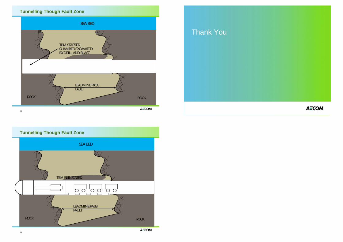
85
SEA BED
ROCK
LEADMINE PASSFAULT
ROCK
TBM STARTER CHAMBER EXCAVATED BY DRILL AND BLAST
Tunnelling Though Fault Zone
86
SEA BED
ROCK
LEADMINE PASSFAULT
ROCK
TBM REINSTATED
Thank You