introduction - mettler toledo robot system robot arm ... small insert grey frame views: side front...
TRANSCRIPT

METTLER TOL
a critical step inenhancing your
mass standards lab !
Product Outline
a1000EDO metrotec
comparator

Table of contents
2
Table of contents
1 Introduction..................................................................................... 3
2 System components......................................................................... 4
3 18-place weight magazine............................................................... 5
4 Performing a weighing process – a1000control makes it easy.......... 12
4.1 Entering and editing the weights data .................................................................12 4.2 Allocating the weight magazine places ...............................................................13 4.3 Determining the weighing process settings and series scheme...............................15 4.4 Choosing the report contents .............................................................................17 4.5 Starting and monitoring the weighing process......................................................17 4.6 Measurement report..........................................................................................18 4.7 "Remote-controlling" the a1000comparator.........................................................22
5 Installation site ............................................................................. 27
6 Technical data............................................................................... 29
7 Dimension drawing........................................................................ 31
Product Outline
a1000 comparator

Introduction
3
1 Introduction Thank you for showing a keen interest in our a1000comparator - a smart weighing automaton! Combining METTLER TOLEDO's world-class weighing sensor technology with metrotec's specific, optimized system design, the ‘a1000comparator’ - automated 1000 g mass comparator - gives a new dimension to high-resolution weighing. Performance and reliability on the one hand, productivity on the other are of concern to metrologists. These aspects were given great attention throughout the development of the a1000comparator. This product offers new ways with respect not only to direct comparison, but to down-/upward calibration as well. a1000comparator and its smart, versatile a1000control software will become in no time indispensable to any mass standards laboratory. (a1000control is an original product designed jointly by metrotec engineering and Raillard engineering.) Among a1000comparator’s numerous remarkable features, let us highlight the essentials:
• “Turn-key” solution for automated comparison weighing processes
• Enhanced measurement quality (in terms of repeatability and reproducibility) and productivity
• Wide scope of application through large weight magazine (18 places) and advanced software capabilities
• Direct comparison and comparison between combinations of up to three weights
• Rugged design and hassle-free maintenance We trust this ‘Product Outline’ will let you realise the tremendous potential which the a1000comparator represents to your mass standards laboratory. Should you request greater detail, please do contact us.
Mettler-Toledo GmbH, Business Area Metrology CH-8606 Greifensee, Switzerland
Phone: +41-1-944 22 11 Fax: +41-1-944 23 70 E-mail: [email protected] Internet: http://www.mt.com
Product Outline
a1000 comparator
System components
4
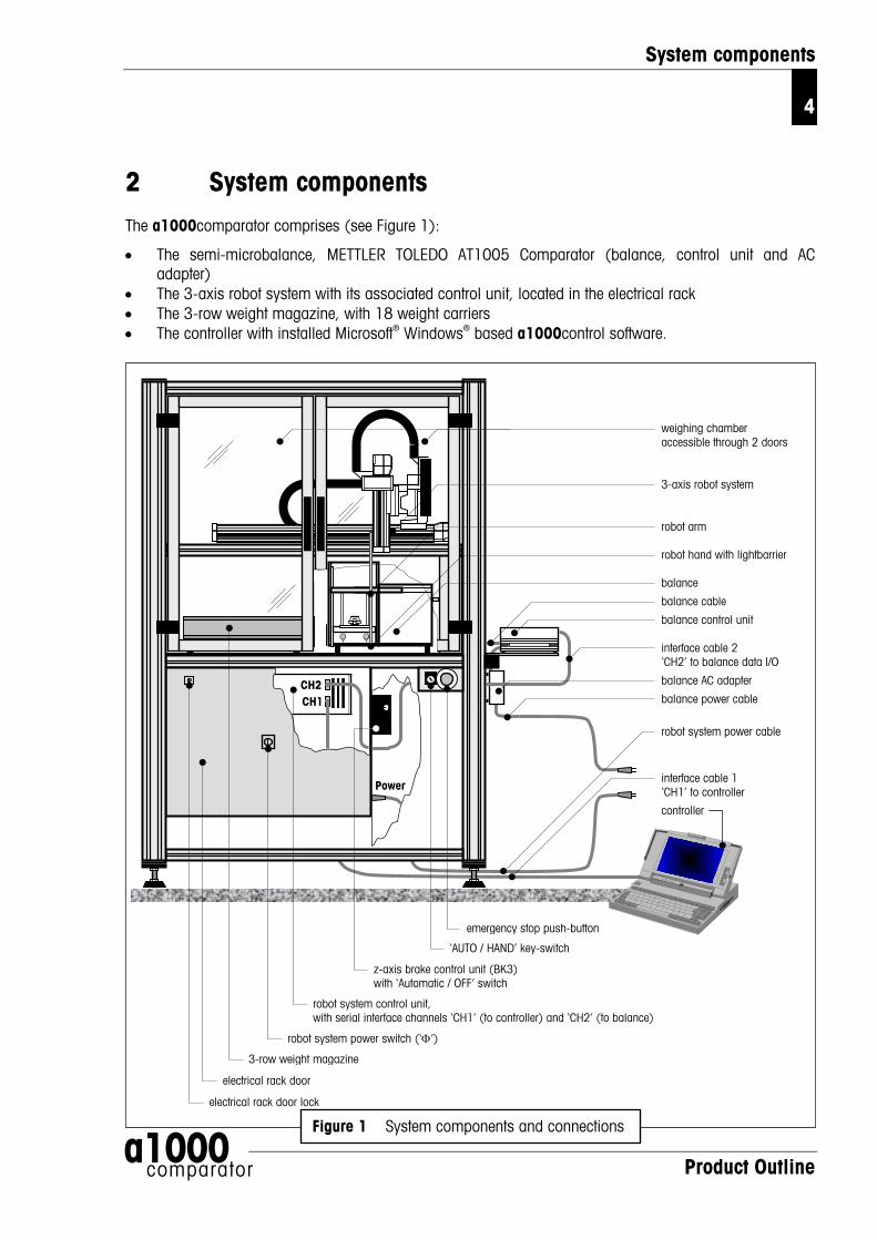
2 System components The a1000comparator comprises (see Figure 1):
• The semi-microbalance, METTLER TOLEDO AT1005 Comparator (balance, control unit and AC adapter)
• The 3-axis robot system with its associated control unit, located in the electrical rack • The 3-row weight magazine, with 18 weight carriers • The controller with installed Microsoft® Windows® based a1000control software.
a1000
weighing chamber accessible through 2 doors 3-axis robot system robot arm robot hand with lightbarrier balance
balance cable
balance control unit interface cable 2 ‘CH2’ to balance data I/O
balance AC adapter
balance power cable
robot system power cable
interface cable 1 ‘CH1’ to controller
controller
CH2 CH1
Power
emergency stop push-button
‘AUTO / HAND’ key-switch
z-axis brake control unit (BK3) with ‘Automatic / OFF’ switch
robot system control unit, with serial interface channels ‘CH1’ (to controller) and ‘CH2’ (to balance)
robot system power switch (‘Φ’)
3-row weight magazine
electrical rack door
electrical rack door lock
Figure 1 System components and connections
Product Outline
comparator

18-place weight magazine
5
3 18-place weight magazine The a1000comparator is delivered with an 18-place weight magazine, equipped with 18 weight carriers. Each test weight / standard used during the weighing process needs to be placed onto one weight carrier (see Figure 2).
Figure 2 Loading the weights onto the weight carriers, and the weight carriers onto the weight magazine
The selection of the adequate weight carrier type (design 1 or 3 - see Figure 3, 4 and 5) is determined by the weight geometry. Strict rules must be followed when it comes to choose, for each weight, the right carrier type, in order to ensure a trouble-free operation of the a1000comparator and to minimize corner load errors. Figures 6, 7 and 8 present the carrier selection criteria.
Product Outline
a1000 comparator

18-place weight magazine
6
Product Outline
1000 comparator
a
small insert
grey frame
views: side front
top
Figure 3 Standard weight carrier design 1, with small, inner inserts

18-place weight magazine
7
Product Outline
a1000 comparator
large insert
grey frame
views: side front
top
Figure 4 Standard weight carrier design 1, with large, outer inserts

18-place weight magazine
8
Product Outline
a1000 comparator
large insert
red frame
views: side front
top
Figure 5 Standard weight carrier design 3, with large inserts

18-place weight magazine
9
Cylindrical with knob
diameter:
10 < dc ≤ 30 mm
height:
hc ≤ 50 mm, if the weight and its carrier are placed on the front magazine row (positions no. a1-a6)
hc ≤ 85 mm, if the weight and its carrier are placed on the middle or back magazine row (positions no. b1-b6, c1-c6)
Warning: weights which do not fit in the above categories shall not be loaded on the above
carrier. Combinations of up to three weights, placed each on its own carrier of design 1 (see above), can be
weighed in the ‘down-/upward calibration’ mode. If a weight placed on a carrier of design 3 (see Figure 8) is involved in the combination, this is limited to two weights only (3-weight combination forbidden!).
top
front
design 1, with set of 4 small, inner inserts
dc
hc
Figure 6 Carrier selection guide and weight positioning
Weight shape Weight dimensions Weight carrier and inserts selection
Product Outline
a1000 comparator

18-place weight magazine
10
Cylindrical with knob
diameter:
30 < dc ≤ 38 mm
height:
hc ≤ 50 mm, if the weight and its carrier are placed on the front magazine row (positions no. a1-a6)
hc ≤ 85 mm, if the weight and its carrier are placed on the middle or back magazine row (positions no. b1-b6, c1-c6)
Warning: weights which do not fit in the above categories shall not be loaded on the above
carrier. Combinations of up to three weights, placed each on its own carrier of design 1 (see above), can be
weighed in the ‘down-/upward calibration’ mode. If a weight placed on a carrier of design 3 (see Figure 8) is involved in the combination, this is limited to two weights only (3-weight combination forbidden!).
top
front
design 1, with set of 4 large, outer inserts
dc
hc
Figure 7 Carrier selection guide and weight positioning (cont'd)
Weight shape Weight dimensions Weight carrier and inserts selection
Product Outline
a1000 comparator

18-place weight magazine
11
Product Outline a1000
Weight shape Weight dimensions Weight carrier and inserts selection
Cylindrical with knob
diameter:
35 < dc ≤ 60 mm
height:
hc ≤ 50 mm, if the weight and its carrier are placed hc on the front magazine row (position no. a1-a6)
hc ≤ 85 mm, if the weight and its carrier are placed on the middle or back magazine row (positions no. b1-b6, c1-c6)
design 3, with set of 4 large inserts
front
top
dc
Warning: weights which do not fit in the above categories shall not be loaded on the above standard carrier.
Combinations of up to three weights, placed each on its own carrier of design 1, can be weighed in the ‘down-/upward calibration’ mode. If a weight placed on a carrier of design 3 (see above) is involved in the combination, this is limited to two weights only (3-weight combination forbidden!).
Figure 8 Carrier selection guide and weight positioning (cont'd)
comparator

Performing a weighing process – a1000control makes it easy
12
4 Performing a weighing process – a1000control makes it easy
A double mouse-click on the a1000control icon (‘a1000control.exe’)
a1000control
starts the program and opens a new, blank process settings file whose main window is shown in Figure 9.
4.1 Entering and editing the weights data
The ‘Weights’ menu (see Figure 10) gives access to the weights database which contains all relevant data on your standards and test weights. While the data on your test weights are, like other settings,
Figure 10 a1000control - ‘Weights’ menu
Figure 9 a1000control - main window
specific to the process and, thus, to the current settings file, the data on your standards are kept in a separate database: these data are specific to your mass standards laboratory, not to the weighing process, and, thus, need to be accessible from any settings file. After selecting ‘Standards data…’ in the ‘Weights’ menu, the window shown in Figure 11 appears. A list box gives all records - all standards - which have been entered. The access to the standards data is password-protected. Once the password is accepted, you may proceed with modifications, i.e.:
Product Outline
a1000 comparator

Performing a weighing process – a1000control makes it easy
13
• Adding new standards into the database • Modifying existing standards • Deleting one (all) existing standards
Figure 11 Entering / editing standards data
A window similar to Figure 11 gives access to the test weights database.
4.2 Allocating the weight magazine places
Once standards and test weights are defined in their respective database, their respective position on the weight magazine needs to be identified and registered in a1000control. This is done in the ‘Allocation of weight magazine places’ window shown in Figure 12. The upper list box contains all defined, and, thus, available weights; the lower one shows all available magazine places, identified by their number, from a1 (right) to a6 (left) for the front, lower magazine row, from b1 (right) to b6 (left) for the middle magazine row and from c1 (right) to c6 (left) for the back, upper magazine row. To allocate one magazine place to one particular weight, simply:
• Select the weight by clicking on the proper record in the upper list box
• Select the magazine place you want to be allocated to the weight you just selected
• Press the ‘Place’ button
Product Outline
a1000 comparator

Performing a weighing process – a1000control makes it easy
14
Figure 12 Allocating weight magazine places (top window) untilall weights used during the process have got a magazineposition assigned to them (bottom window)
Product Outline
a1000 comparator

Performing a weighing process – a1000control makes it easy
15
4.3 Determining the weighing process settings and series scheme
After defining standards and test weights and determining on which magazine place each of these weights is located, the comparisons, of which the weighing process shall consist, as well as their precise timing and sequence are to be set. As shown in Figure 13, various parameters serve to determine the process, such as, in particular:
Figure 13 Setting the process parameters
• ‘Weighing mode’: ‘One-vs.-one comparisons’ – direct comparisons, between a single weight B and a single weight A - or ‘Down-/upward calibration’ - comparison between two combinations of up to three weights each - (professional software edition; optional); the ‘standard’ software allows ‘One-vs.-one comparisons' only
• ‘Comparison scheme’: you may choose either the ‘A-B-A’ or ‘A-B-B-A’ scheme
Product Outline
a1000 comparator
• ‘Sensitivity check’: should you wish to monitor the balance “sensitivity” during the weighing process, you may select ‘Check after each series’; the sensitivity check - determination of the value of the check standard (to be selected) - will be performed before the first series starts and at the end of each series.

Performing a weighing process – a1000control makes it easy
16
After setting these parameters, it remains to determine the series scheme (design), i.e. which comparisons shall be performed and in which sequence. A separate window (‘Series scheme’, see Figure 14) makes it as easy as it can possibly be. The upper list boxes ‘Weight B:’ and ‘Weight A:’ both contain all available weights, i.e. all test weights and all standards to which one magazine place is allocated. The series scheme, displayed in the lower list boxes (‘Scheme - Weight B:’ and ‘Scheme - Weight A:’), consists of a list of comparisons between two combinations of up to three weights each. Each comparison is entered as follows:
• Select first the weight B by clicking on the proper record in the upper ‘Weight B:’ list box
• Press the ‘Add B’ button: the selected weight B is entered in the ‘Scheme - Weight B:’ list box
• If you wish to enter a combination of more than one weight, repeat the previous two steps (the symbol ‘+’ in the ‘Scheme’ list boxes indicates that a combination is entered - see Figure 14 - and the total nominal value of the combination is displayed on the top of the ‘Scheme’ list boxes)
• Once the (combination of) weight(s) B is entered, select the weight A by clicking on the proper record in the upper ‘Weight A:’ list box
• Press the ‘Add A’ button: the selected weight A is entered in the ‘Scheme - Weight A:’ list box
• If you wish to enter a combination of more than one weight A, repeat the two previous steps.
Figure 14 Complete series scheme in mode‘Down-/upward calibration’
Product Outline
a1000 comparator

Performing a weighing process – a1000control makes it easy
17
4.4 Choosing the report contents
The weighing process is now defined: a1000control has registered which standards and test weights are involved in this process, where on the magazine these weights are located, it has registered the timing which has to be followed throughout the process and the scheme which defines all comparisons and their sequence. All parameters are set. Before starting the weighing process, the contents of the report file can be defined, by selecting the information blocks you want to get reported:
• Weighing process settings • Magazine places allocation • Series scheme • Balance settings • Measurement data • Summary of results.
4.5 Starting and monitoring the weighing process
The start command is given by selecting ‘Start measurement’ in the ‘Start’ menu. a1000control then displays some information on the process timing (see Figure 15). Once the “go” command is given, the weighing process monitor (see Figure 16) allows you to follow the process on-line, step by step. The two upper boxes ‘Weight B:’ and ‘Weight A:’ show which comparison is currently being carried out. The large text box records every single process step and displays the detailed measurement data, in a format which is similar to the report format. Furthermore, it provides in the ‘status field’ useful information on the current action, as well as valuable advice with respect to troubleshooting, should an error be detected.
Product Outline
a1000 comparator
Figure 15 Weighing process information – Timing and maximum balance load

Performing a weighing process – a1000control makes it easy
18
example of contents of status field after error detection
status field during operation
Figure 16 Weighing process monitor
4.6 Measurement report
The Figures 17, 18 and 19 show a report generated by a1000control after running a weighing process consisting of one series of 7 groups of 5 A-B-A comparison weighings. The selected weighing mode is ‘Down-/upward calibration’. Figure 17 presents the report heading, Figure 18 the measurement data and Figure 19 the results summary table from which you get, at a glance, the essentials in a compact, but explicit format. Should the process consist of more than one series, the summary table indicates, in addition, the average of the difference averages.
Product Outline
a1000 comparator

Performing a weighing process – a1000control makes it easy
19
a1000control v4.5 - measurement report File: D:\metrotec\a1000comparator\a1000control\a1000control reports\TestReport.doc a1000control settings defined in: D:\metrotec\a1000comparator\a1000control\1000g-100g.1e3 Start date 15 Nov 2000 User metrotec engineering ag Start time 18:09:33 Notes determination of TestSet 1000g - 100g Weighing process time [h:min] 7:25 Weighing process settings --------------------------------------------------------------------------------------------------- Pre-run done Yes History-specific pause enabled [min] 20 Start delay [h:min] 02:00 No. of non-reported pre-weighings per group 3 No. of reported comparisons per group 5 No. of series 1 Comparison scheme A-B-A Stabilisation time [s] 25 Integration time [s] 5 Sensitivity check done Yes b3 : S MySet 100g 100.0g 0.090mg 8000.000kg/m^3 Magazine places allocation ------------------------------------------------------------------------------------------------------------------- b1 : S MySet 1000g 1000.0g 0.420mg 8000.000kg/m^3 b2 : S MySet 500g 500.0g -0.220mg 8000.000kg/m^3 b3 : S MySet 100g 100.0g 0.090mg 8000.000kg/m^3 c1 : T TestSet 1000g 1000.0g 8000.000kg/m^3 c2 : T TestSet 500g 500.0g 8000.000kg/m^3 c3 : T TestSet 200g 200.0g 8000.000kg/m^3 c4 : T TestSet 200g* 200.0g 8000.000kg/m^3 c5 : T TestSet 100g 100.0g 8000.000kg/m^3 Series scheme (B vs. A) ------------------------------------------------------------------------------------------------------------------- 1: c1 : T TestSet 1000g 1000.0g 8000.000kg/m^3 vs. b1 : S MySet 1000g 1000.0g 0.420mg 8000.000kg/m^3 ------------------------------------------------------------------------------------------------------------------- 2: c2 : T TestSet 500g 500.0g 8000.000kg/m^3 + b2 : S MySet 500g 500.0g -0.220mg 8000.000kg/m^3 vs. c1 : T TestSet 1000g 1000.0g 8000.000kg/m^3 ------------------------------------------------------------------------------------------------------------------- 3: b2 : S MySet 500g 500.0g -0.220mg 8000.000kg/m^3 vs. c2 : T TestSet 500g 500.0g 8000.000kg/m^3 ------------------------------------------------------------------------------------------------------------------- 4: c3 : T TestSet 200g 200.0g 8000.000kg/m^3 + c4 : T TestSet 200g* 200.0g 8000.000kg/m^3 + c5 : T TestSet 100g 100.0g 8000.000kg/m^3 vs. c2 : T TestSet 500g 500.0g 8000.000kg/m^3 ------------------------------------------------------------------------------------------------------------------- 5: c4 : T TestSet 200g* 200.0g 8000.000kg/m^3 vs. c3 : T TestSet 200g 200.0g 8000.000kg/m^3 ------------------------------------------------------------------------------------------------------------------- 6: c5 : T TestSet 100g 100.0g 8000.000kg/m^3 + b3 : S MySet 100g 100.0g 0.090mg 8000.000kg/m^3 vs. c3 : T TestSet 200g 200.0g 8000.000kg/m^3 ------------------------------------------------------------------------------------------------------------------- 7: b3 : S MySet 100g 100.0g 0.090mg 8000.000kg/m^3 vs. c5 : T TestSet 100g 100.0g 8000.000kg/m^3 ------------------------------------------------------------------------------------------------------------------- Balance settings ------------------------------------------------------------------------------------------------------------------- Mass comparator ID AX1005 Environment very stable Value release very fast Last adjustment (internal) 13 Nov 2000, 17:13:25 Climate data ------------------------------------------------------------------------------------------------------------------- Climate data input online Climate measuring instrument Klimet A30
Figure 17 Report - Part 1: heading and process settings
Product Outline
a1000 comparator

Performing a weighing process – a1000control makes it easy
20
-------------------------------------------------------------------------------------------------------------------------------------------------------------------------- Day/Time Meas.no. Place(s) Value Diff.(B-A) Diff.average WeightB-error Std.dev. Press.[hPa] rel.Hum.[%] T1[degr.C] T2[degr.C] T3[degr.C] T4[degr.C] 15/20:28:51 00 sc 0 -0.260 972.213 37.94 22.658 22.315 22.691 22.710 15/20:30:03 00 sc b3 99999.850 972.213 37.94 22.658 22.315 22.691 22.710 15/20:31:15 00 sc 0 -0.230 100000.095 100000.095 972.177 37.64 22.668 22.336 22.695 22.714 15/20:42:17 010101A b1 -654.770 972.213 37.94 22.658 22.315 22.691 22.710 15/20:43:52 010101B c1 -654.230 972.213 37.94 22.658 22.315 22.691 22.710 15/20:45:27 010101A b1 -654.770 0.540 972.177 37.64 22.668 22.336 22.695 22.714 15/20:47:01 010102B c1 -654.220 972.177 37.64 22.668 22.336 22.695 22.714 15/20:48:36 010102A b1 -654.770 972.203 37.46 22.677 22.348 22.697 22.714 15/20:50:11 010102B c1 -654.230 0.545 972.203 37.46 22.677 22.348 22.697 22.714 15/20:51:46 010103A b1 -654.770 972.207 37.31 22.679 22.353 22.685 22.704 15/20:53:20 010103B c1 -654.220 972.146 37.16 22.683 22.356 22.678 22.699 15/20:54:55 010103A b1 -654.760 0.545 972.146 37.16 22.683 22.356 22.678 22.699 15/20:56:29 010104B c1 -654.220 972.138 37.11 22.687 22.363 22.677 22.700 15/20:58:04 010104A b1 -654.760 972.138 37.11 22.687 22.363 22.677 22.700 15/20:59:38 010104B c1 -654.210 0.545 972.104 36.97 22.691 22.371 22.680 22.702 15/21:01:13 010105A b1 -654.760 972.036 36.90 22.706 22.402 22.712 22.731 15/21:02:48 010105B c1 -654.220 972.036 36.90 22.706 22.402 22.712 22.731 15/21:04:23 010105A b1 -654.758 0.539 0.543 0.827 0.003 972.038 36.73 22.716 22.417 22.717 22.739 15/21:26:41 010201A c1 -654.170 972.213 37.94 22.658 22.315 22.691 22.710 15/21:28:56 010201B c2 + b2 -656.755 972.213 37.94 22.658 22.315 22.691 22.710 15/21:31:11 010201A c1 -654.160 -2.590 972.177 37.64 22.668 22.336 22.695 22.714 15/21:33:26 010202B c2 + b2 -656.760 972.177 37.64 22.668 22.336 22.695 22.714 15/21:35:41 010202A c1 -654.158 972.203 37.46 22.677 22.348 22.697 22.714 15/21:37:55 010202B c2 + b2 -656.747 -2.596 972.203 37.46 22.677 22.348 22.697 22.714 15/21:40:09 010203A c1 -654.140 972.207 37.31 22.679 22.353 22.685 22.704 15/21:42:24 010203B c2 + b2 -656.745 972.146 37.16 22.683 22.356 22.678 22.699 15/21:44:38 010203A c1 -654.148 -2.601 972.146 37.16 22.683 22.356 22.678 22.699 15/21:46:52 010204B c2 + b2 -656.750 972.138 37.11 22.687 22.363 22.677 22.700 15/21:49:06 010204A c1 -654.150 972.138 37.11 22.687 22.363 22.677 22.700 15/21:51:21 010204B c2 + b2 -656.730 -2.590 972.104 36.97 22.691 22.371 22.680 22.702 15/21:53:34 010205A c1 -654.130 972.036 36.90 22.706 22.402 22.712 22.731 15/21:55:50 010205B c2 + b2 -656.720 972.036 36.90 22.706 22.402 22.712 22.731 15/21:58:04 010205A c1 -654.110 -2.600 -2.595 0.005 972.038 36.73 22.716 22.417 22.717 22.739 15/22:09:25 010301A c2 -589.180 972.213 37.94 22.658 22.315 22.691 22.710 15/22:11:01 010301B b2 -591.010 972.213 37.94 22.658 22.315 22.691 22.710 15/22:12:37 010301A c2 -589.180 -1.830 972.177 37.64 22.668 22.336 22.695 22.714 15/22:14:12 010302B b2 -591.010 972.177 37.64 22.668 22.336 22.695 22.714 15/22:15:48 010302A c2 -589.170 972.203 37.46 22.677 22.348 22.697 22.714 15/22:17:23 010302B b2 -591.003 -1.836 972.203 37.46 22.677 22.348 22.697 22.714 15/22:18:58 010303A c2 -589.170 972.207 37.31 22.679 22.353 22.685 22.704 15/22:20:35 010303B b2 -591.000 972.146 37.16 22.683 22.356 22.678 22.699 15/22:22:10 010303A c2 -589.165 -1.832 972.146 37.16 22.683 22.356 22.678 22.699 15/22:23:46 010304B b2 -591.003 972.138 37.11 22.687 22.363 22.677 22.700 15/22:25:22 010304A c2 -589.180 972.138 37.11 22.687 22.363 22.677 22.700 15/22:26:57 010304B b2 -591.010 -1.826 972.104 36.97 22.691 22.371 22.680 22.702 15/22:28:32 010305A c2 -589.178 972.036 36.90 22.706 22.402 22.712 22.731 15/22:30:08 010305B b2 -591.010 972.036 36.90 22.706 22.402 22.712 22.731 15/22:31:43 010305A c2 -589.160 -1.841 -1.833 0.006 972.038 36.73 22.716 22.417 22.717 22.739 15/22:54:50 010401A c2 -589.132 972.213 37.94 22.658 22.315 22.691 22.710 15/22:57:54 010401B c3 + c5 + c4 -580.110 972.213 37.94 22.658 22.315 22.691 22.710 15/23:00:55 010401A c2 -589.130 9.021 972.177 37.64 22.668 22.336 22.695 22.714 15/23:03:59 010402B c3 + c5 + c4 -580.110 972.177 37.64 22.668 22.336 22.695 22.714 15/23:07:00 010402A c2 -589.136 972.203 37.46 22.677 22.348 22.697 22.714 15/23:10:04 010402B c3 + c5 + c4 -580.110 9.026 972.203 37.46 22.677 22.348 22.697 22.714 15/23:13:05 010403A c2 -589.130 972.207 37.31 22.679 22.353 22.685 22.704 15/23:16:08 010403B c3 + c5 + c4 -580.110 972.146 37.16 22.683 22.356 22.678 22.699 15/23:19:09 010403A c2 -589.120 9.015 972.146 37.16 22.683 22.356 22.678 22.699 15/23:22:11 010404B c3 + c5 + c4 -580.110 972.138 37.11 22.687 22.363 22.677 22.700 15/23:25:11 010404A c2 -589.130 972.138 37.11 22.687 22.363 22.677 22.700 15/23:28:14 010404B c3 + c5 + c4 -580.112 9.019 972.104 36.97 22.691 22.371 22.680 22.702 15/23:31:16 010405A c2 -589.130 972.036 36.90 22.706 22.402 22.712 22.731 15/23:34:19 010405B c3 + c5 + c4 -580.110 972.036 36.90 22.706 22.402 22.712 22.731 15/23:37:20 010405A c2 -589.120 9.015 9.019 0.005 972.038 36.73 22.716 22.417 22.717 22.739
Figure 18 Report - Part 2: measurement data
Product Outline
a1000 comparator

Performing a weighing process – a1000control makes it easy
21
Series scheme (B vs. A) and summary of results (in mg) Diff.average WeightB-error Std.dev. -------------------------------------------------------------------------------------------------------------------- 1: c1 : T TestSet 1000g 1000.0g 8000.000kg/m^3 Series 1: 0.543 0.827 0.003 vs. b1 : S MySet 1000g 1000.0g 0.420mg 8000.000kg/m^3 -------------------------------------------------------------------------------------------------------------------- 2: c2 : T TestSet 500g 500.0g 8000.000kg/m^3 Series 1: -2.595 0.005 + b2 : S MySet 500g 500.0g -0.220mg 8000.000kg/m^3 vs. c1 : T TestSet 1000g 1000.0g 8000.000kg/m^3 -------------------------------------------------------------------------------------------------------------------- 3: b2 : S MySet 500g 500.0g -0.220mg 8000.000kg/m^3 Series 1: -1.833 0.006 vs. c2 : T TestSet 500g 500.0g 8000.000kg/m^3 -------------------------------------------------------------------------------------------------------------------- 4: c3 : T TestSet 200g 200.0g 8000.000kg/m^3 Series 1: 9.019 0.005 + c4 : T TestSet 200g* 200.0g 8000.000kg/m^3 + c5 : T TestSet 100g 100.0g 8000.000kg/m^3 vs. c2 : T TestSet 500g 500.0g 8000.000kg/m^3 -------------------------------------------------------------------------------------------------------------------- 5: c4 : T TestSet 200g* 200.0g 8000.000kg/m^3 Series 1: 6.090 0.007 vs. c3 : T TestSet 200g 200.0g 8000.000kg/m^3 -------------------------------------------------------------------------------------------------------------------- 6: c5 : T TestSet 100g 100.0g 8000.000kg/m^3 Series 1: 3.653 0.004 + b3 : S MySet 100g 100.0g 0.090mg 8000.000kg/m^3 vs. c3 : T TestSet 200g 200.0g 8000.000kg/m^3 -------------------------------------------------------------------------------------------------------------------- 7: b3 : S MySet 100g 100.0g 0.090mg 8000.000kg/m^3 Series 1: -3.539 0.004 vs. c5 : T TestSet 100g 100.0g 8000.000kg/m^3 -------------------------------------------------------------------------------------------------------------------- sc: b3 : S MySet 100g 100.0g 0.090mg 8000.000kg/m^3 Start: 100000.095 Series 1: 100000.095 -------------------------------------------------------------------------------------------------------------------- ---------------------------------------------------------------------------------------------------
Indication of corner load error
a1000control automatically handles the comparison of two weight combinations in such a way (placing sequence) that the remaining corner load error is minimized. In the case of a comparison '200 g + 200 g + 100 g' vs. '500 g', the combination entered as '200 g + 200 g + 100 g' will be placed onto the balance pan in the sequence '200 g + 100 g + 200 g': the center of gravity of the weights combination is located on the same vertical axis as the 500 g weight and, consequently, the remaining corner load error equals zero. However, in certain cases, in particular when non OIML weights are involved in a combination (e.g. '300 g + 200 g' vs. '500 g'), a certain error due to corner load remains. Knowing the measured corner load error, a1000control calculates for each comparison the remaining error due to corner load and, if not zero, indicates it under 'CrLd-err' in the results summary table of the measurement report (see Figure 20).
Series scheme (B vs. A) and summary of results (in mg) Diff.average WeightB-error Std.dev. --------------------------------------------------------------------------------------------------- 1: b10: T TestSet 300g 300.0g Series 1: 0.460 0.240 0.005 + b9 : T TestSet 200g 200.0g Series 2: 0.458 0.238 0.004 vs. b8 : S MySet 500g 500.0g -0.220mg Average : 0.459 0.239 CrLd-err: -0.060 --------------------------------------------------------------------------------------------------- Figure 20 Indication of corner load error
Figure 19 Report - Part 3: summary of results
Product Outline
a1000 comparator

Performing a weighing process – a1000control makes it easy
22
4.7 “Remote-controlling” the a1000comparator
The weighing process settings may need to be generated by a central laboratory information management system, such as for instance the ‘Automated Mass Measurement System’ (AMMS) supplied by Measurement Technology Laboratories (Minneapolis, USA), and imported from this system into a1000control. Furthermore certain commands may need to be sent to a1000control from this central system, in order to let this system “remote-control” the a1000comparator. a1000control offers such an interface which fully meets these requirements.
4.7.1 Generating a file importable into a1000control as settings file
As above mentioned, the ability of a1000control to import a settings file generated by a central information management system is indispensable to certain laboratories. To achieve this, a text file needs to be produced by this central system according to well-defined format rules, so that it becomes convertible into a regular, a1000control-compatible settings file (see Figure 22 and following table). Figure 21 presents an example of such a text file, named ‘ImportDemo.imp’ and containing all necessary settings.
JOB: ImportDemo a1000control 3 HEADER: <This is an optional 3-line text block which appears in a message box when the new settings file (imported and converted into a1000control) is loaded> END HEADER PROCESS: 1 1 2 0 3 5 1 A-B-A 25 5 b3 20 END PROCESS MAGAZINE: b1 S MySet 1000g 1000 0.42 8000.0 b2 S MySet 500g 500 -0.22 8000.0 b3 S MySet 100g 100 0.09 8000.0 c1 T TestSet 1000g 1000 c2 T TestSet 500g 500 c3 T TestSet 200g 200 c4 T TestSet 200g* 200 c5 T TestSet 100g 100 END MAGAZINE SCHEME: c1 VS. b1 c2+b2 VS. c1 b2 VS. c2 c3+c4+c5 VS. c2 c4 VS. c3 c5+b3 VS. c3 b3 VS. c5 END SCHEME REPORT: metrotec engineering ag C:\Programs\a1000control\DemoOutput END REPORT END JOB ImportDemo
Product Outline
a1000 comparator
Figure 21 Example of a text file convertible into a settings file by a1000control

Performing a weighing process – a1000control makes it easy
23
JOB: strJobID<CR LF> strAppName intDocVersion<CR LF> [HEADER:<CR LF> strHeaderLine<CR LF> [strHeaderLine<CR LF> [strHeaderLine<CR LF>]] END HEADER] PROCESS:<CR LF> blnWeighingMode blnPreRun intStartDelayHours intStartDelayMinutes intNonReportedPreweighings intReportedComparisons intSeries strComparisonScheme intStabilisationTime intIntegrationTime strSensitivityCheck intHistorySpecificPause<CR LF> END PROCESS<CR LF> MAGAZINE:<CR LF> strPosID strWeightType strSetID strWeightID decNominal[ decError]<CR LF> […] END MAGAZINE<CR LF> SCHEME:<CR LF> strCombination VS. strCombination<CR LF> […] END SCHEME<CR LF> REPORT:<CR LF> strUserName<CR LF> strFileName<CR LF> END REPORT<CR LF> END JOB strJobID<CR LF>
Product Outline
a1000 comparator
Parameter designation Value (range) Description
strJobID <no limitation> string of characters used as job identification
strAppName ‘a1000control’ designation of control software used
intDocVersion 3 document version used as internal reference to the settings definition and its history
strHeaderLine <no limitation> text appearing in a message box when loading the imported and converted settings file
blnWeighingMode 0 1 ‘0’ = 1 vs. 1 comparisons, ‘1’ = down-/upward calibration
blnPrerun 0 1 ‘0’ = pre-run not requested, ‘1’ = pre-run requested
intStartDelayHours 0 – 99 integer, number of hours in time requested as start delay
intStartDelayMinutes 0 – 59 integer, number of minutes in time requested as start delay
intNonReportedPreweighings 0 – 5 integer, number of non-reported pre-weighings per group
Figure 22 Format of a text file convertible into an a1000control settings file (<CR LF> means ‘carriage return linefeed’ and [ ] optional )

Performing a weighing process – a1000control makes it easy
24
Parameter designation Value (range) Description (cont’d)
intReportedComparisons 1 – 20 integer, number of reported comparisons per group
intSeries 1 – 20 integer, number of series
strComparisonScheme ‘A-B-A’ ‘A-B-B-A’ comparison scheme
intStabilisationTime 10 – 60 integer, stabilisation time in seconds
intIntegrationTime 0 – 60 integer, integration time in seconds
strSensitivityCheck strPosID ‘NO’ mag. place of sens. check standard if check done, ‘NO’ if not
intHistorySpecificPause 0 – 60 integer, duration of history-specific pause in minutes
strPosID ‘a’ ‘b’ ‘c’ & ‘1’ ‘2’ …‘6’ magazine position number: a1 to a6, b1 to b6, c1 to c6
strWeightType ‘S’ ‘T’ ‘S’ = standard, ‘T’ = test weight
strSetID <maximum 8 characters> string of maximum 8 characters, weight set identification
strWeightID <maximum 8 characters> string of maximum 8 characters, weight identification
decNominal 0 – 1109 number (with decimal), weight nominal value in g
decError <no limitation, in principle> number (with decimal), error in mg given for standards only (i.e. strWeightType = ‘S’)
strCombination strPosID[+strPosID [+strPosID]] string consisting of up to 3 different magazine positions, separated by the ‘+’ sign
strUserName <maximum 54 characters> string of maximum 54 characters (including spaces), user identification
strFileName <file location path and name> name of report file, without extension, and its location on disk
Meaning of the symbols used in the above table
‘< >’ delimits a comment on the value of a parameter, ‘–’ means ‘up to’, ‘ ’ stands for ‘or’, ‘[ ]’ delimits an optional block and ‘&’ indicates the concatenation of two strings of characters.
The file generated according to the above rules (extension ‘.imp’) can now be imported into a1000control and converted into a settings file. Before doing so, you need to choose the data import mode between importing from file (accessible locally on disk or via local area network) and importing via a serial communication port. Should the latter be selected, a second serial communication port has to be available - in addition to the port used for communication to the a1000comparator weighing machine.
Product Outline
a1000 comparator

Performing a weighing process – a1000control makes it easy
25
4.7.2 Communicating via the serial port
As mentioned earlier on, the ‘.imp’ text file generated by the laboratory information management system (LIMS) can be imported into a1000control via a serial communication port. The communication protocol is fixed: 2400 baud, 7 data bits, 1 stop bit, parity even; besides, a fixed time out of 3 seconds is defined during which the reply to a request for data must be sent. To ensure a smooth exchange of information between the LIMS and a1000control, the following set of commands is available:
Task, description Command a1000control LIMS Command LIMS a1000control
Requesting list of pending jobs, pressing ‘Get job list’ button
JOB ?<CR LF>
Sending list of pending jobs (empty list if none available)
JOB[ strJobID[ strJobID[…]]]<CR LF>
Requesting one particular job, pressing ‘Load job’ command button
JOB strJobID<CR LF>
Sending one particular job <text file as described in Section 4.7.1>
Accepting job (file syntax and consistency o.k.), saving job as settings file
JOB strJobID OK<CR LF>
Rejecting job (file syntax and consistency not o.k.)
JOB strJobID DENIED<CR LF>
Advising of job start and estimated duration, befo-re pre-run/centering starts
JOB strJobID STARTS DURATION: intHours:intMinutes<CR LF>
Advising of job end, after job successfully comple-ted
JOB strJobID SUCCESSFULLY ENDED<CR LF>
Advising of job end due to program failure, after program aborted
JOB strJobID ABORTED<CR LF>
Advising of job end due to ‘Abort’ command given by user
JOB strJobID ABORTED BY USER<CR LF>
The output data, i.e. the measurement results, can be sent out via the serial communication port and processed on line by the LIMS. While the weighing process is running, a1000control sends out the measurement data - without heading -, contained in the first four columns (‘Time’, ‘Measurement number’, ‘Place(s)’ and ‘Value’) of the measurement data block of the report presented in Figure 18, for example:
Product Outline
a1000 comparator

Performing a weighing process – a1000control makes it easy
26
20:28:51 00 sc 0 -0.260<CR LF> 20:30:03 00 sc b3 99999.850<CR LF> 20:31:15 00 sc 0 -0.230<CR LF> 20:42:17 010101A b1 -654.770<CR LF> 20:43:52 010101B c1 -654.230<CR LF> 20:45:27 010101A b1 -654.770<CR LF> … 01:44:46 01 sc 0 0.040<CR LF> 01:45:57 01 sc b3 100000.140<CR LF> 01:47:09 01 sc 0 0.050<CR LF> After the weighing process is successfully completed, a1000control sends out via the serial port a final data block containing the corner load error, in mg, calculated for each measurement group. The block format is as follows: CORNERLOAD decCrLd_err1[ decCrLd_err2[ decCrLd_err3[ …]]]<CR LF> where ‘decCrLd_err1’ is the corner load error calculated for the first measurement group, ‘decCrLd_err2’ the corner load error calculated for the second measurement group etc. Should the error calculated for a particular group equal zero or not have been measured, the value indicated for the error is ‘NO’ or ‘UNKNOWN’ respectively. An example of a complete block is given below, advising of the following corner load errors: 0 for the first group, 0.060 mg for the second group, -0.050 mg for the third group and ‘unknown’ because not measured for the fourth and last group. CORNERLOAD NO 0.060 –0.050 UNKNOWN<CR LF>
4.7.3 Upgrading a1000control
To upgrade (see Figure 23) the a1000control to the ‘professional’ one (optional; Down/-upward calibration), or to enable online climate data input (optional; Temperature, Relative humidity, Pressure), you need to purchase the software options separately.
Figure 23 Upgrading the a1000control software
Product Outline
a1000 comparator

Installation site
27
5 Installation site The a1000comparator comprises the robot system and the balance, which are both to be attached separately to the floor. For this purpose, the balance is installed on a separate bench, attached to the floor by 2 screws; the robot system itself needs, to be properly attached, 2 screws as well. Figure 22 shows the footprint of the a1000comparator and defines the position of the holes which need to be drilled in the floor. Besides, you need to ensure that at least 30 cm free space is available on both sides and at the back of the a1000comparator; in the front the two doors which give access to the weighing chamber need at least 60 cm free space to open. The weighing room should ideally
• be as insensitive as possible to shocks and vibrations
• have only one door (drafts)
• be as free from drafts as possible (important with air conditioning systems)
• be in the basement
• be well insulated
• contain as few heat sources as possible (it is better to locate all computers and other peripherals in an anteroom).
The room temperature should be between 17 and 27°C. Temperature fluctuations within minutes should be kept as small as possible. The air temperature should not change by more than +/- 0.5°C over one hour. Relatively large, long-term fluctuations (summer/winter) are entirely permissible. The relative humidity should be between 40 and 70%. The relative humidity should not change by more than +/- 5% over one hour. Relatively large, long-term fluctuations (summer/winter) are entirely permissible.
Product Outline
a1000 comparator

Installation site
28
0
0
2
830
190
140
610
110
a1000comparator’s footprint
front
Figure 24 P o
a1000 comparator
1180
osition and dimensions f the holes for floor attachment
Prod
250
24
1100
424
Ø 12 x 70
Ø 12 x 70
Ø 8 x 70
Ø 8 x 70
uct Outline

Technical data
29
Product Outline
6 Technical data Balance - METTLER TOLEDO AX1005 Comparator
Readability 0.01 mg
Maximum capacity 1109 g
Electrical weighing range 109 g
Repeatability Determined as standard deviation of 10 ‘one-vs.-one’ comparative weighings, after drift elimination:
s ≤ 0.01 mg - typical value: 0.005 mg
Linearity ± 0.12 mg
Stabilisation time 10...20 s
Adjustment Motorized adjustment of the electrical range at a keystroke (built-in 2 x 100 g adjustment weights)
Automated weight handler
Weight handler For automatic determination of test weights, by direct comparison of one test weight with one standard, or, as an option, by down- / upward calibration - comparison between combinations of up to three weights, as described in ‘Weight carrier selection guide’, Section 3
Measuring time (typical) 15 min. for a series of 5 ‘one-vs.-one’ A-B-A comparative weighings, 30 min. for a series of 5 ‘three-vs.-one’ A-B-A comparative weighings
Test weights / standards Cylindrical, knob-shaped weights with a nominal value of 10 g - 1000 g and geometry as follows (see Section 3):
• single weight and 2-weight combination: 10 ≤ weight diameter ≤ 60 mm, height ≤ 85 mm
• 3-weight combination: 10 ≤ weight diameter ≤ 38 mm, height ≤ 85 mm
Weight magazine 18 places
Control software Microsoft® Windows®-based a1000control, compatible with Windows®95, Windows®98, WindowsNT® and WindowsXP®
Data interface RS232C to controller
a1000 comparator

Technical data
30
Product Outline
Technical data (cont’d) Admissible ambient conditions
Temperature 17 - 27 °C (± 0.5 °C / hour)
Relative humidity 40 - 70 % (± 5 %)
Vibrations A set-up in a “vibration-free” room is recommended
Overvoltage category Class II
Degree of pollution 2
AC adapter
Voltage - Balance control unit 100-240V (-15%/+10 %), 0.7A - Robot system control unit 115 V or 230 V (-20% - +15 %)
Frequency - Balance control unit 50 Hz / 60 Hz - Robot system control unit 50 Hz / 60 Hz
Power consumption - Handler 150 VA max.
Dimensions (w x d x h) / net weight
Handler and balance 1430 x 890 x 1730 mm / 308 kg
a1000 comparator

Dimension drawing
31
7 Dimension drawing
1430
1180
890
1730
Product Outline
a1000 comparator

This document (version 3.4, July 2003) is subject to technical changes.
© 2003 Mettler-Toledo GmbH and metrotec engineering ag
Product Outline
a1000 comparator