introduction lise simion
TRANSCRIPT


Introduction› Creation of fusion-evaporation products› Proposed Experimental Set-up› Gas Stopper
Simulation Results› LISE› SIMION
Conclusion Future Work Acknowledgements

My research focuses on 158Hf, which is a homolog of 257Rf
Why do we care about Rf?
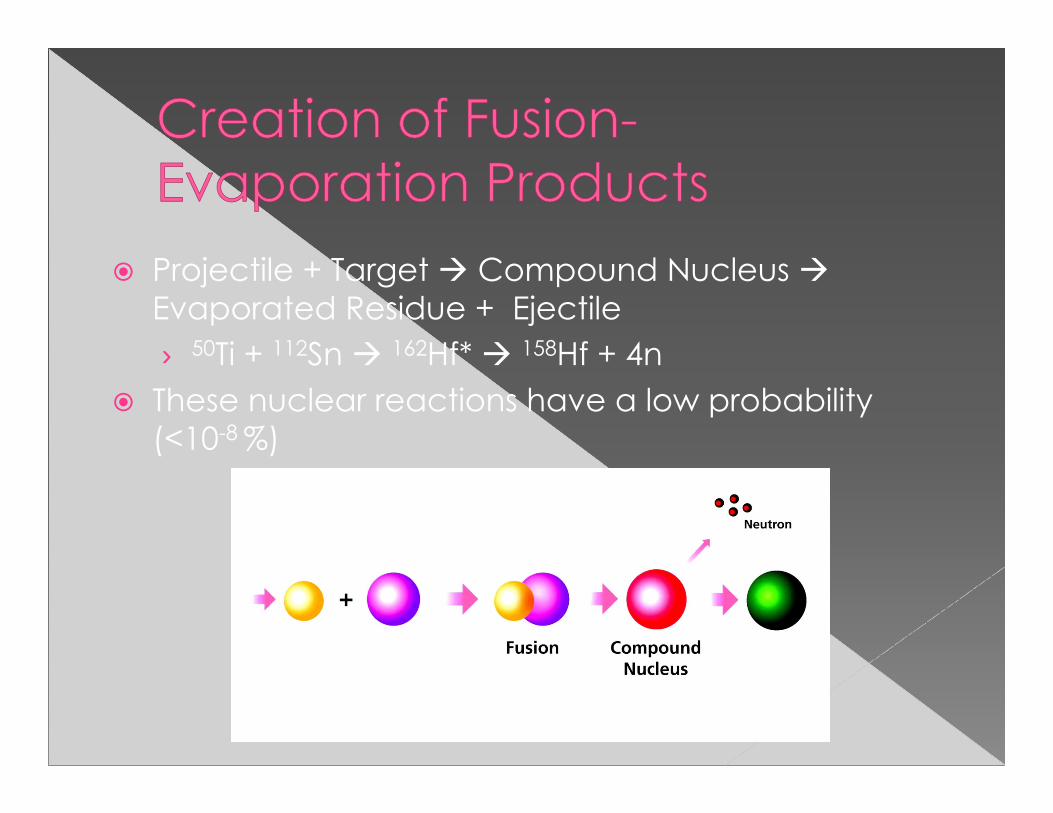
Projectile + Target Compound Nucleus Evaporated Residue + Ejectile› 50Ti + 112Sn 162Hf* 158Hf + 4n
These nuclear reactions have a low probability (<10-8 %)

Momentum Achromat Recoil Separator (MARS) will filter out unwanted products and beam
Main components of my simulations: variable angle degrader, Reaction Transfer Chamber (RTC) window, & helium gas cell

Beam From Cyclotron
TargetMARS
Physical Pre-Separator
Variable Angle Degrader Recoil Transfer Chamber
(RTC) Window
Gas Stopper
To Chemistry Experiments
θ
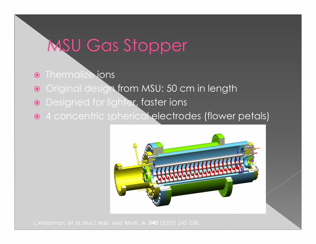
Thermalize ions Original design from MSU: 50 cm in length Designed for lighter, faster ions 4 concentric spherical electrodes (flower petals)
L.Weissman, et al. Nucl. Instr. and Meth. A. 540 (2005) 245-258.

Our design, adapted from MSU: 13.5 cm in length Optimized for heavier, slower ions 4 flower petals like original design Voltage decreases across the gas stopper
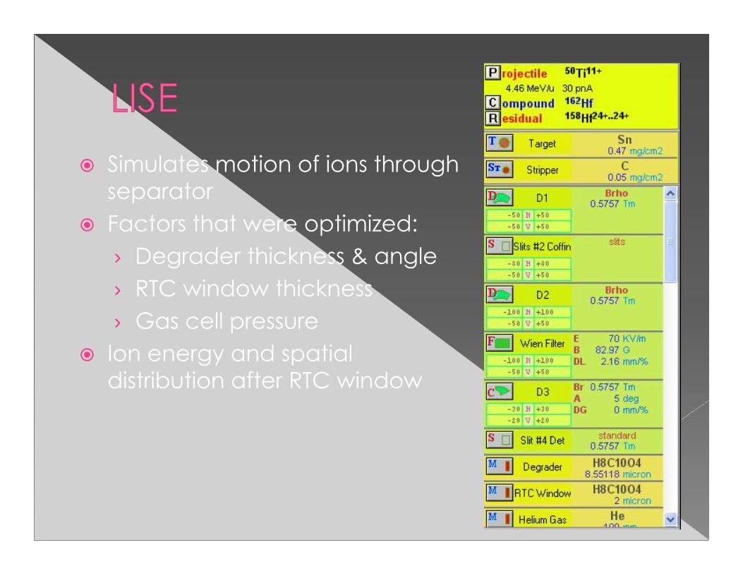
Simulates motion of ions through separator
Factors that were optimized:› Degrader thickness & angle› RTC window thickness› Gas cell pressure
Ion energy and spatial distribution after RTC window

Vertical Distribution Horizontal Distribution
Location Distribution after RTC Window
Mean: 0 mm, σ: 17 mm Mean: 0 mm, σ: 21 mm
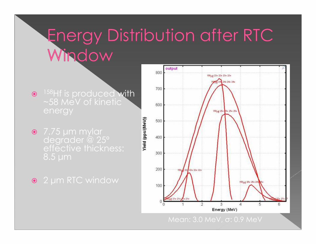
Mean: 3.0 MeV, σ: 0.9 MeV
158Hf is produced with ~58 MeV of kinetic energy
7.75 μm mylar degrader @ 25º effective thickness: 8.5 μm
2 μm RTC window

Ion simulation program that calculates electric fields and trajectories of ions for those electric fields
Ion energy and spatial distribution determined by LISE Mobility: (17.7 cm2 V-1 s-1) [1] Gas flow: 11.5 mm/sec in beam direction Collisions with He SRIM range of 158Hf in
0.3 atm of He
[1] R. Johnsen, et al. J. Chem. Phys. 57 (1972) 5292-5295.

High survival rate & low kinetic energy is needed 3 different simulations
0
0.1
0.2
0.3
0.4
0.5
0.6
0.7
0 200 400 600 800 1000 1200 1400 1600Ave
rage
Kin
etic
Ene
rgy
(ev)
Potential Applied (V)
Average Kinetic Energy vs. Potential Difference
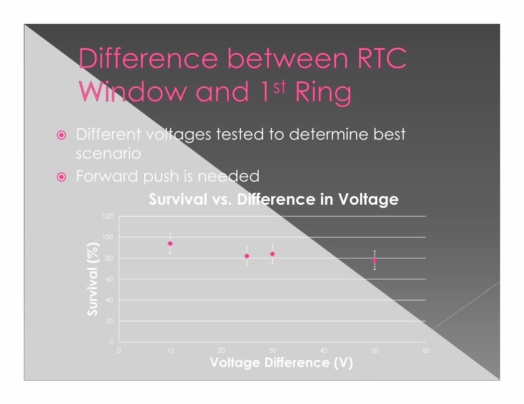
Different voltages tested to determine best scenario
Forward push is needed
0
20
40
60
80
100
120
0 10 20 30 40 50 60
Surv
ival
(%)
Voltage Difference (V)
Survival vs. Difference in Voltage

Too many ions stopped by 1st electrode
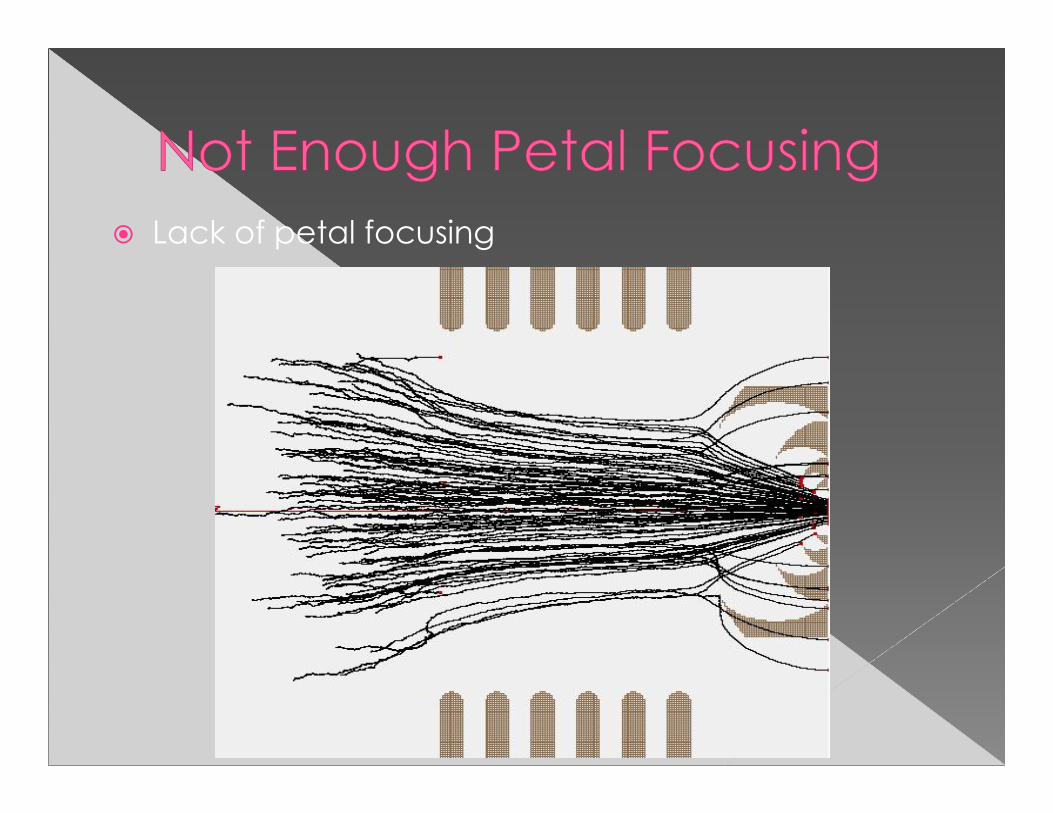
Lack of petal focusing
710 700
550
575600625650675
200400
500
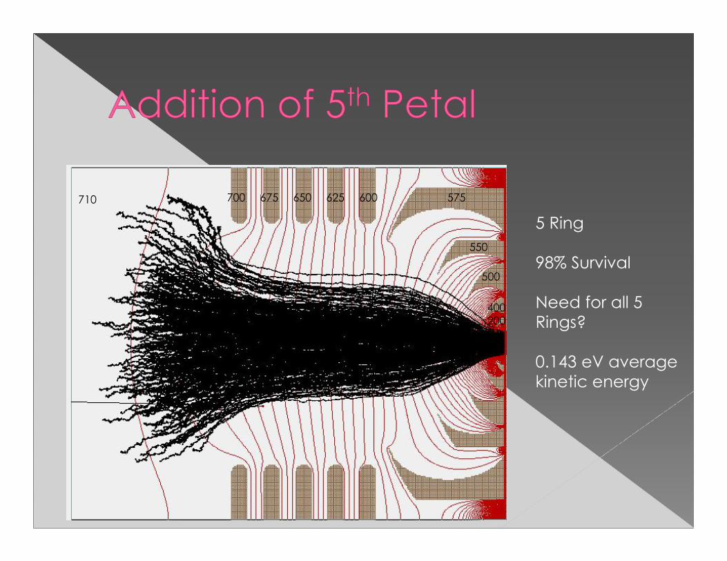
5 Ring
98% Survival
Need for all 5 Rings?
0.143 eV average kinetic energy

660
400
500
550
575625 600650
200
3 Ring
Makes the cell smaller
96% Survival
0.146 eV average kinetic energy

Like before, less of a difference proves to be better
0
20
40
60
80
100
120
0 10 20 30 40 50 60 70 80
Surv
ival
(%)
Voltage Difference (V)
Survival vs. Difference between RTC Window and 1st Ring
An RTC window voltage was optimized at 710 V, then decreased down the length of the stopper
Can decrease ions from ~3 MeV to ~0.14 eV in just 115.5 mm
Ion spatial distribution decreased vertically from 17 mm to 1.5 mm and horizontally from 21 mm to 1.8 mm
3 ring electrodes is sufficient in steering the ions

Further simulate the gas cell for other similar elements, such as zirconium
Fabricate and test the gas cell
More sophisticated gas flow
Charge exchange

National Science Foundation Department of Energy Texas A&M Cyclotron Institute Dr. Sherry Yennello
Special thanks to my advisor, Dr. Folden, and my graduate student mentor, Marisa Alfonso