introduction – dr andrew beath - energy · pdf file11:00 inauguration of workshop by...
TRANSCRIPT

1
12th November 2006
Kolkata, India
�Dr Andrew Beath
�CSIRO Exploration & Mining
�Australia
�Dr Cliff Mallett
�Carbon Energy Pty Ltd
�AustraliaSupported by the Australian Government through the Asia Pacific Partnership (AP6) Coal Mining Task Force
Tutorial on Underground Coal Gasification (UCG)
Outline of today’s activities9:00 Session 1:
o Introductionso Fundamentals & UCG design
10:45 Morning tea11:00 Inauguration of Workshop by Shri Shibu Soren, Hon’ble Minister of
Coal, India & Keynote address by :Shri H.C. Gupta, Secretary (Coal)11:20 Session 2:
o Behaviour predictiono Process performance & economic viability
1:00 Lunch2:00 Session 3:
o Groundwater & surface impactso Site selection & characterisationo Social perceptions
3:30 Afternoon tea3:45 Session 4:
o Case studyo Discussion
5:00 Finish
12th November 2006
Kolkata, India
�Dr Andrew Beath
�CSIRO Exploration & Mining
�Australia
�Dr Cliff Mallett
�Carbon Energy Pty Ltd
�AustraliaSupported by the Australian Government through the Asia Pacific Partnership (AP6) Coal Mining Task Force
Session 1A: Introduction
Introduction – Dr Andrew Beath
Dr Andrew Beath is a chemical engineer with a varied range of experience in industry and research. Over the last 7 years he has developed models to predict the growth of UCG cavities and the product gas properties, as well as simulation of processes which could utilise the product gas.
Introduction – Dr Cliff Mallett
Dr Cliff Mallett is a geologist with a long and varied career in research. Until recently he was Deputy Chief of CSIRO Exploration and Mining, where he initiated the research programme into underground coal gasification. He is now Executive General Manager of Carbon Energy, a company launched to commercialise the outcomes of CSIRO’s UCG research.
Research background
The CSIRO UCG research programme commenced in 1998. The major outcome has
been a series of models and methodologies for:
oSite characterisation
oCavity growth and gas production
oGeotechnical behaviour
oHydrogeological flows
oOverall process performance
The rights to commercial use of these are now owned by Carbon Energy.

2
12th November 2006
Kolkata, India
�Dr Andrew Beath
�CSIRO Exploration & Mining
�Australia
�Dr Cliff Mallett
�Carbon Energy Pty Ltd
�AustraliaSupported by the Australian Government through the Asia Pacific Partnership (AP6) Coal Mining Task Force
Session 1B: Fundamentals
Fundamentals of Coal Gasification
�INPUTS
Coal
Oxygen/Air
Water
�OUTPUTS
Synthesis/Fuel gas
H2,CH4,CO,CO2
Char, Tar & Water
Heat
O2
Gas
Characteristics of UCG
�Underground coal gasification is like other coal gasification techniques, except that the geological strata form the reaction vessel.
�This adds a level of complexity to analysis of the behaviour of the process and leads to extra uncertainty due the geological environment.
A simple guide to UCG
UCG can be condensed to two areas of analysis that are indicated on the
next two slides:
�Reaction processes
�Physical site changes
Each can be considered separately, but it is interaction of these that makes UCG analysis complex.
Reaction Processes
Product gas
Drying, Volatile release &
Gasification
Drying & Volatile release
Combustion&
High temperatures
Gas reduction&
Moderate temperatures
Gas equilibrium reactions& Cooling
Drying
Feed gas
Physical Site Changes
Water Table
IncreasedPermeability
Surface subsidence
Water usage
Contamination
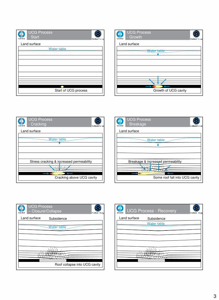
3
UCG Process- Start
Water tableLand surface
Start of UCG process
UCG Process- Growth
Water table
Land surface
Growth of UCG cavity
UCG Process- Cracking
Water table
Land surface
Cracking above UCG cavity
Stress cracking & increased permeability
UCG Process- Breakage
Water table
Land surface
Some roof fall into UCG cavity
Breakage & increased permeability
UCG Process – Closure/Collapse
Water table
Land surface
Roof collapse into UCG cavity
Subsidence
UCG Process - Recovery
Water table
Land surface Subsidence

4
Outline of key UCG topics
4. Site selection& characterisation
1. UCG Design &Behaviourprediction
2. Process performance& economic viability
3. Groundwater &surface impacts
5. Socialperceptions
6. Case studyanalysis 12th November 2006
Kolkata, India
�Dr Andrew Beath
�CSIRO Exploration & Mining
�Australia
�Dr Cliff Mallett
�Carbon Energy Pty Ltd
�AustraliaSupported by the Australian Government through the Asia Pacific Partnership (AP6) Coal Mining Task Force
Session 1C: UCG Design
What affects UCG design?
�Coal seam dip (slope)
�Coal seam depth
�Coal permeability
�Overburden properties
�Drilling capabilities
�Required production volume
�Restrictions on subsidence and groundwater consumption
�Process stability requirements
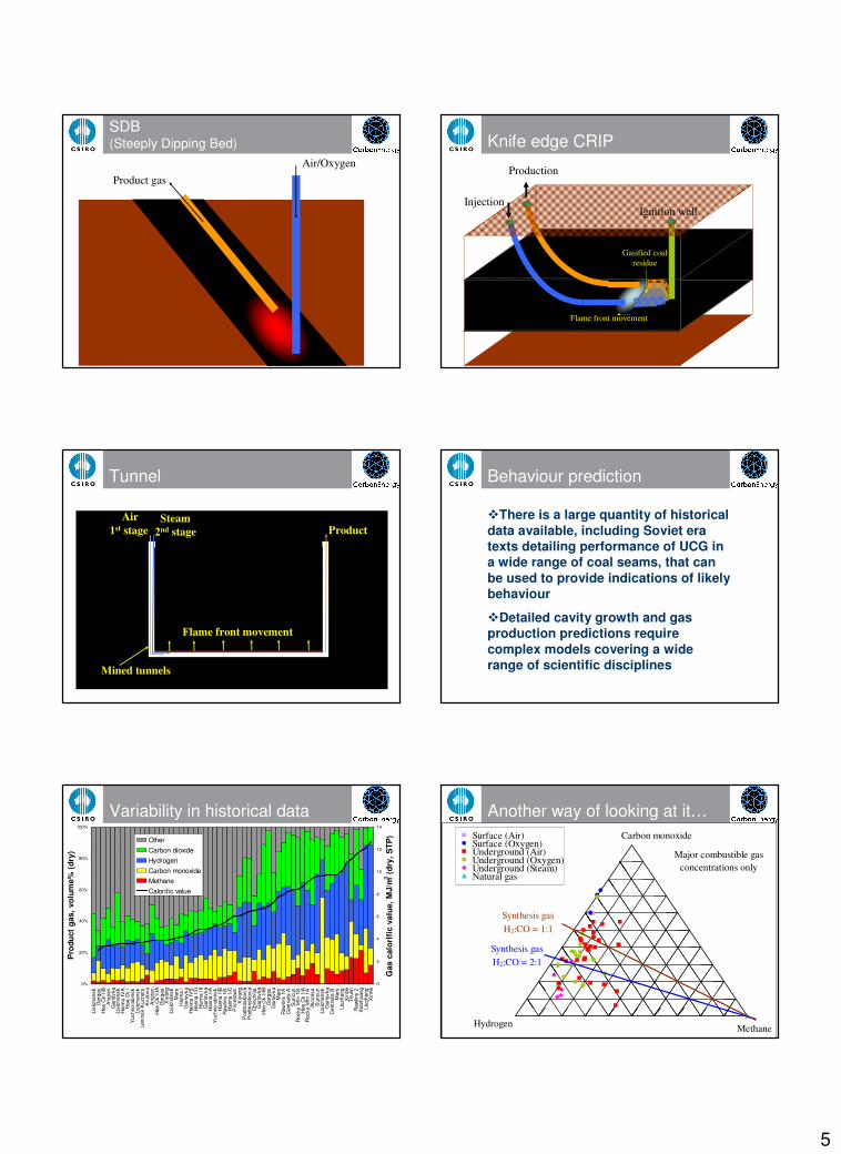
Historical UCG designs
�Vertical Wells
�CRIP (Controlled Retracting Injection Point)
�SDB (Steeply Dipping Bed)
�Knife edge CRIP
�Tunnel
Vertical wellsAir Product
Exhausted holes
CRIP (Controlled Retracting Injection Point)
Product
1st CRIP reactor
Air/Oxygen
2nd CRIP reactor
5
SDB(Steeply Dipping Bed)
Product gasAir/Oxygen
Knife edge CRIP
Injection
Production
Gasified coal residue
Flame front movement
Ignition well
Tunnel
Air1st stage Product
Mined tunnels
Steam2nd stage
Flame front movement
Behaviour prediction
�There is a large quantity of historical data available, including Soviet era texts detailing performance of UCG in a wide range of coal seams, that can be used to provide indications of likely behaviour
�Detailed cavity growth and gas production predictions require complex models covering a wide range of scientific disciplines
Variability in historical data
0%
20%
40%
60%
80%
100%
Lisi
chan
skG
orga
sH
oe C
k II
BA
ngre
nG
orlo
vka
Lisi
chan
skH
anna
IV
AH
oe C
k I
Yuz
hno-
abin
skLi
sich
ansk
Leni
nsk-
Kuz
nets
Kru
tova
Ang
ren
Hoe
Ck
IIIA
Gor
gas
Xiy
ang
Lisi
chan
skM
ars
Han
na I
Gor
lovk
aH
anna
IV
BH
anna
IID
Han
na I
IIG
orlo
vka
Han
na I
IAY
uzhn
o-ab
insk
Han
na I
IBR
awlin
s 1B
Han
na I
ICP
ricet
own
Xiy
ang
Pod
mos
kovi
aP
odm
osko
via
Chi
nchi
llaG
orlo
vka
Hoe
Ck
IIIB
Gor
gas
Gor
lovk
aM
ars
Raw
lins
1AC
entr
alia
AS
uncu
nR
ocky
Mtn
1B
Hoe
Ck
IIA
Roc
ky M
tn 1
AA
lcor
isa
Sun
cun
Lisi
chan
skG
orlo
vka
Cen
tral
ia B
Mar
sLi
uzha
ngX
inhe
Thul
inR
awlin
s 2
Xie
zhua
ngLi
uzha
ngX
inhe
Pro
duct
gas
, vol
ume%
(dr
y)
0
2
4
6
8
10
12
14
Gas
cal
orif
ic v
alue
, MJ/
m3 (
dry,
STP
)OtherCarbon dioxideHydrogenCarbon monoxideMethaneCalorific value
Another way of looking at it…Surface (Air)Surface (Oxygen)Underground (Air)Underground (Oxygen)Underground (Steam)Natural gas
Hydrogen
Carbon monoxide
Methane
Major combustible gas concentrations only
Synthesis gas H2:CO = 2:1
Synthesis gas H2:CO = 1:1

6
Literature trend from Skafa (1960)-Gas quality vs Seam thickness
0
1
2
3
4
5
6
0 1 2 3 4 5 6 7 8 9 10
Seam thickness, m
Pro
duct
gas
cal
orifi
c va
lue,
MJ/
m3
(dry
, STP
)
1 m3 of water/t of coal gasified
2 m3 of water/t of coal gasified
3 m3 of water/t of coal gasified
4 m3 of water/t of coal gasified
Literature trend from Skafa (1960)-Gas quality vs Ash content
0
0.5
1
1.5
2
2.5
3
3.5
4
4.5
0 10 20 30 40 50 60 70 80 90 100
Ash content of coal, %ad
Cal
orifi
c va
lue
of p
rod
uct
gas,
MJ/
m3 (d
ry, S
TP)
Summary
Some of the more obvious features that impact on UCG product gas quality are:
�Seam thickness
�Water influx
�Ash content
�Feed gas composition
Why do these have impact?
�Energy balance
oHeat loss to overburden
oVaporisation of water
�Mass balance
oRatio of C:H:O in reactions
oCoal recovery efficiency
Ash content impact
Ash content has an unusual impact:
�Ash replaces carbonaceous material, so reduces the effective quantity of coal and would be expected to reduce the efficiency
�But, this does not happen until ash contents over 40% occur
�Ash provides a thermal repository that stabilises gasification and can have a beneficial effect in some circumstances (eg. thin clay or stone bands in the coal seam)
12th November 2006
Kolkata, India
�Dr Andrew Beath
�CSIRO Exploration & Mining
�Australia
�Dr Cliff Mallett
�Carbon Energy Pty Ltd
�AustraliaSupported by the Australian Government through the Asia Pacific Partnership (AP6) Coal Mining Task Force
The End