introduction attenuators - emc-rflabs - emc · pdf fileemc technology8851 sw old kansas ave....
TRANSCRIPT

EMC Technology 8851 SW Old Kansas Ave. Stuart FL 34997 (772) 286-9300 (800) 544-5594 www.emct.com A Smiths Group company19
Features• Substrate - Alumina
• Power Rating - 0.1 to 2 Watts
• Frequency Range DC to 18 GHz
• Tape and Reel Packaging Available
• VSWR under 1.50:1
• Variety of Chip Sizes
• Attenuation Values from 1 to 20 dB in
1 dB increments; consult the factory
for fractional and higher attenuation
values.
• S-Parameter Files Available
• Surface Mount and Lead Attachment
Versions Available
Applications• Circulators
• Coaxial Attenuator Components
• Filters
• High Power Amplifiers
• Instrumentation
• Isolators
• Military
• Signal Sampling
• Interstage Isolation
• Impedance Matching
AttenuatorsIntroduction
General Specifications ............................................20TS03 Chip ..............................................................22TS04 Chip ..............................................................24TS05 Chip ..............................................................26
Table of Contents
EMC Technology’s attenuators areavailable in a low power chip package.The power ratings range from 0.1 to 2watts. The attenuation values rangefrom 1 dB to 20 dB. The terminals ofEMC chip attenuators are made withthick film base material that is nickelplated and solder coated. The resistiveelement is thin film offering superior electrical performance. The TS04 seriesuses thick film resistor elements. Thedevices are available for shipping intray or tape and reel packaging.
Frequency DimensionsSeries Range (GHz) (Inches)TS03 DC-12.4 .145 x .122TS04 DC-2.5 .100 x .125TS05 DC-18 .075 x .060
Quick Selector Chart

EMC Technology 8851 SW Old Kansas Ave. Stuart FL 34997 (772) 286-9300 (800) 544-5594 www.emct.com A Smiths Group company20
General Specifications Attenuators
Notes:
• Contact the factory for specifications for fractional and higher attenuation values.• Performance is based on a device mounted in a matched 50Ω line and is highly dependent upon device mounting.
See Application Note 003 on page 61 and Application Note 004 on page 66 for mounting instructions.• Rated input power is 2.0 watts on TS03 Series, 100mw on TS05 Series, and 1 watt on the TS04 Series.• Maximum peak input power is 50 watts on TS03 Series chips and 1 watt on TS05 Series chips. Duty cycle is 1%
with a pulse width of 10 microseconds.• Full rated power to 125°C, derate linearly to 0 watts at 150°C.• Tight tolerance chip attenuators and 0.5 dB increments available upon request. Please contact factory.
Increment DC - 2.5 GHz DC - 4 GHz 4 - 8 GHz 8 - 12.4 GHz 12.4 - 18 GHz(dB) TS04XX TS03XX, W1, W3 TS03XX, W1, W3 TS03XX TS05 & G
TS05XX, G, W1, TS05XX, G, W1, TS05XX, G, W1, Series OnlyWB1, W3 Series WB1, W3 Series WB1, W3 Series
1 - 3 ± 0.3 dB ± 0.3 dB ± 0.5 dB ± 0.5 dB ± 0.5 dB
4 - 6 ± 0.4 dB ± 0.4 dB ± 0.5 dB ± 0.5 dB ± 0.75 dB
7 - 10 ± 0.5 dB ± 0.5 dB ± 0.5 dB ± 0.75 dB ± 1.0 dB
11 - 15 ± 0.75 dB ± 0.75 dB + 0.5/- 3.0 dB + 0.5/- 3.5 dB -
16 - 20 ± 1.0 dB ± 1.0 dB + 0.5/- 4.0 dB + 1.0/- 6.0 dB
Attenuation Accuracy
Chip Attenuator KitsTS03 and TS05 Series KitsOur chip attenuator kits are perfect for designers who need fast, convenient and accurate fine tuning of attenuationvalues for microwave circuits. Each kit is comprised of 50 attenuator chips, with five chips each of ten differentattenuation values ranging from 1 to 10 dB. The following kits are available: TS03XX, TS03XXW3, TS05XX,TS05XXWB1 and TS05XXW3.
See page 58 for attenuator kit selection guide.

EMC Technology 8851 SW Old Kansas Ave. Stuart FL 34997 (772) 286-9300 (800) 544-5594 www.emct.com A Smiths Group company21
General Specifications Attenuators
Planar Configuration W1/WB1 Configuration
W3 Configuration
Metallization Options• Planar (no code) Planar device for flip chip mounting
offers the best RF performance andlowest cost.
• Leaded (T3) Leads/tabs (gold plated copper);requires top plate.
• Triple Wrap (W3) Metallization wraps around input,output, and ground terminals.Permits inspectable solder filletswhen flip chip mounting. SeeApplication Note 004 on page 66.
• Single Wrap (W1) Metallization wraps around ground terminal only. Full backsidemetallization.
• Pretinned (S) Pretinned (with Sn 62) terminalsimprove solderability (available onall of the above options).
• Lead Free (F) Lead free, pure tin plating options areavailable (excludes WB1 and G met-allization options).
• Single Wrap (WB1) (TS05 series only) Metallization wraps around ground terminal only. Full backside metallization. Input and output terminals have gold metallization.
• Gold (G) (TS05 series only) Planar device withgold metallization. Typically used for wirebonding.
Available with top plate and tabs (T3).

EMC Technology 8851 SW Old Kansas Ave. Stuart FL 34997 (772) 286-9300 (800) 544-5594 www.emct.com A Smiths Group company22
TS03 Chip Attenuators
General Specifications
Impedance . . . . . . . . . . . . . . . . 50 Ohms NominalAttenuation Stability . . . . . . . . . 0.0001 dB /dB/C˚VSWR (Max) . . . . . . . . . . . . . .1.25 @ DC-4 GHz
1.35 @ 4-8 GHz1.50 @ 8-12.4 GHz
Power Rating . . . . . . . . . . . . . . . . . . . . . 2.0 WattsPower Derating . . . . . . . . . . . . . . .100% @ 125° C
Derates to 0% @ 150° COperating Temperature . . . . . . . . -55° C to 150° C
Material Specifications
Substrate . . . . . . . . . . . . . . . . . . . . . . . . . AluminaResistive Element . . . . . . . . . . . . . . . . . Thin Film
Termination Material . . Thick Film, Nickel Barrierwith Solder Plated Finish
EMC Technology’s TS03 chip attenuators offer powerdissipation up to 2 watts and are designed to work fromDC to 12.4 GHz. High reliability and tight toleranceoptions are available.
Ordering InformationTS 0 3 20 S
CHIP ATTENUATORTS = StandardHR = High Reliability
TestingTT = Tight Tolerance
ATTENUATION VALUEin whole dB steps (00 through 20)
TOP PLATE0 = No Top Plate9 = Top Plate
with Leads
CHIP SIZE3 = .122 x .145
OPTIONS(blank) = Planar
W1 = Wrap-around GroundW3 = Wrap-around, All TermsT3 = Leaded
Note: Contact factory for details regarding precision tight tolerance(TT) attenuators.
Dimensions (TS03XX Series)
PRETINNING(blank) = Standard
S = PretinningF = Lead Free

EMC Technology 8851 SW Old Kansas Ave. Stuart FL 34997 (772) 286-9300 (800) 544-5594 www.emct.com A Smiths Group company23
TS03 Chip Attenuators
TS03XX Series TS03XXW1 Series
TS03 Style
TS03XXW3 Series TS93XXT3 Series

EMC Technology 8851 SW Old Kansas Ave. Stuart FL 34997 (772) 286-9300 (800) 544-5594 www.emct.com A Smiths Group company24
TS04 Chip Attenuators
General Specifications
Impedance . . . . . . . . . . . . . . . . 50 Ohms NominalAttenuation Stability . . . . . . . . . 0.0001 dB /dB/C˚VSWR (Max) . . . . . . . . . . .1.25 @ DC to 2.5 GHzPower Rating . . . . . . . . . . . . . . . . . . . . . 1.0 WattsPower Derating . . . . . . . . . . . . . . . .100% @ 85° C
Derates to 0% @ 150° COperating Temperature . . . . . . . . -55° C to 150° C
Material Specifications
Substrate . . . . . . . . . . . . . . . . . . . . . . . . . AluminaResistive Element . . . . . . . . . . . . . . . . . Thick Film
Termination Material . . Thick Film, Nickel Barrierwith Solder Plated Finish
EMC Technology’s TS04 chip attenuators offer powerdissipation up to 1 Watt and are designed to work infrequencies from DC to 2.5 GHz. The TS04 series chipattenuators are designed for telecom commercial frequency bands and perform optimally in low power,narrow band applications.
Ordering InformationTS 0 4 03
CHIP ATTENUATORTS = Standard
ATTENUATION VALUE01 = 1 dB 02 = 2 dB03 = 3 dB06 = 6 dB 10 = 10 dB 20 = 20 dB
TOP PLATE0 = No Top Plate
CHIP SIZE4 = .100 x .125
Dimensions (TS04XX Series)

EMC Technology 8851 SW Old Kansas Ave. Stuart FL 34997 (772) 286-9300 (800) 544-5594 www.emct.com A Smiths Group company25
TS04 Chip Attenuators
TS04XX Series
TS04 Style

EMC Technology 8851 SW Old Kansas Ave. Stuart FL 34997 (772) 286-9300 (800) 544-5594 www.emct.com A Smiths Group company26
TS05 Chip Attenuators
General Specifications
Impedance . . . . . . . . . . . . . . . . 50 Ohms NominalAttenuation Stability . . . . . . . . . 0.0001 dB /dB/C˚VSWR (Max) . . . . . . . . . . . . . .1.25 @ DC-4 GHz
1.35 @ 4-8 GHz1.50 @ 8-18 GHz
Power Rating . . . . . . . . . . . . . . . . . . . . . . 100 mWPower Derating . . . . . . . . . . . . . . .100% @ 125° C
Derates to 0% @ 150° COperating Temperature . . . . . . . . -55° C to 150° C
Material Specifications
Substrate . . . . . . . . . . . . . . . . . . . . . . . . . AluminaResistive Element . . . . . . . . . . . . . . . . . Thin Film
Termination Material . . Thick Film, Nickel Barrierwith Solder Plated Finish
Gold and Wire Bondable options available
EMC Technology’s TS05 chip attenuators offer powerdissipation up to 100 mW and are designed to work infrequencies from DC to 18 GHz. High reliability and tighttolerance options are available.
Ordering InformationTS 0 5 20 S
CHIP ATTENUATORTS = StandardHR = High Reliability
TestingTT = Tight Tolerance
ATTENUATION VALUEin whole dB steps (00 through 20)
TOP PLATE0 = No Top Plate9 = Top Plate
with Leads
CHIP SIZE5 = .060 x .075
OPTIONS(blank) = Planar
G = Gold W1 = Wrap-around GroundW3 = Wrap-around, All Terms
WB1 = Gold Input/Output, Wrap-around Ground
T3 = Leaded, Top Plate Required
Dimensions (TS05XX/TS05XXG Series)
PRETINNING(blank) = Standard
S = PretinningF = Lead Free
Not available onWB1 or G
Note: Contact factory for details regarding precision tight tolerance(TT) attenuators.

EMC Technology 8851 SW Old Kansas Ave. Stuart FL 34997 (772) 286-9300 (800) 544-5594 www.emct.com A Smiths Group company27
TS05 Chip Attenuators
TS05XX/TS05XXG Series TS05XXW1/WB1 Series
TS05XXW3 Series
TS05 Style
TS95XXT3 Series
EMC Technology 8851 SW Old Kansas Ave. Stuart FL 34997 (772) 286-9300 (800) 544-5594 www.emct.com A Smiths Group company28
General Specifications Attenuators
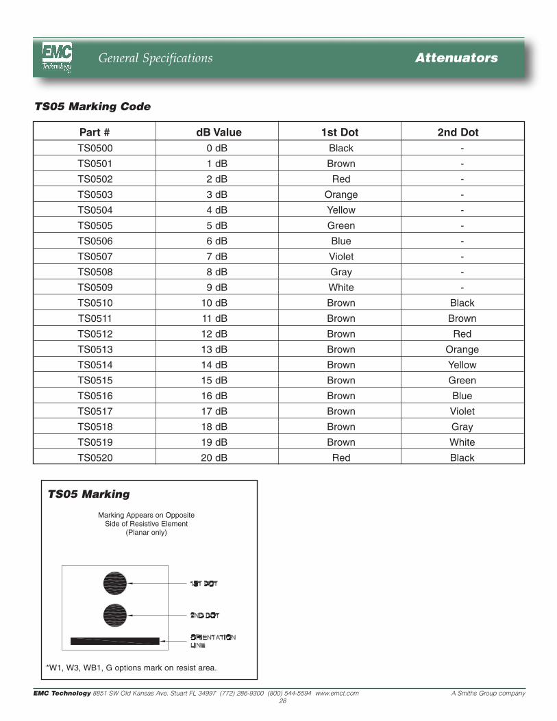
Part # dB Value 1st Dot 2nd DotTS0500 0 dB Black -
TS0501 1 dB Brown -
TS0502 2 dB Red -
TS0503 3 dB Orange -
TS0504 4 dB Yellow -
TS0505 5 dB Green -
TS0506 6 dB Blue -
TS0507 7 dB Violet -
TS0508 8 dB Gray -
TS0509 9 dB White -
TS0510 10 dB Brown Black
TS0511 11 dB Brown Brown
TS0512 12 dB Brown Red
TS0513 13 dB Brown Orange
TS0514 14 dB Brown Yellow
TS0515 15 dB Brown Green
TS0516 16 dB Brown Blue
TS0517 17 dB Brown Violet
TS0518 18 dB Brown Gray
TS0519 19 dB Brown White
TS0520 20 dB Red Black
TS05 Marking Code
TS05 Marking
*W1, W3, WB1, G options mark on resist area.