introduction 1 2 v4.1 ruggedcom ros 3 4 5 6 · ruggedcom ros v4.1 user guide for rsg2100, rsg2100p,...
TRANSCRIPT

RUGGEDCOM ROSv4.1
User Guide
For RSG2100, RSG2100P, M2100
12/2014
Preface
Introduction 1
Using ROS 2
Device Management 3
System Administration 4
Setup and Configuration 5
Troubleshooting 6
RC1118-EN-02

RUGGEDCOM ROSUser Guide
ii
Copyright © 2014 Siemens Canada Ltd.
All rights reserved. Dissemination or reproduction of this document, or evaluation and communication of its contents, is not authorizedexcept where expressly permitted. Violations are liable for damages. All rights reserved, particularly for the purposes of patent application ortrademark registration.
This document contains proprietary information, which is protected by copyright. All rights are reserved. No part of this document may bephotocopied, reproduced or translated to another language without the prior written consent of Siemens Canada Ltd..
Disclaimer Of LiabilitySiemens has verified the contents of this manual against the hardware and/or software described. However, deviations between the productand the documentation may exist.
Siemens shall not be liable for any errors or omissions contained herein or for consequential damages in connection with the furnishing,performance, or use of this material.
The information given in this document is reviewed regularly and any necessary corrections will be included in subsequent editions. Weappreciate any suggested improvements. We reserve the right to make technical improvements without notice.
Registered TrademarksROX™, Rugged Operating System On Linux™, CrossBow™ and ELAN™ are trademarks of Siemens Canada Ltd. . ROS® is a registeredtrademark of Siemens Canada Ltd..
Other designations in this manual might be trademarks whose use by third parties for their own purposes would infringe the rights of theowner.
Third Party CopyrightsSiemens recognizes the following third party copyrights:
• Copyright © 2004 GoAhead Software, Inc. All Rights Reserved.
Security InformationSiemens provides products and solutions with industrial security functions that support the secure operation of plants, machines, equipmentand/or networks. They are important components in a holistic industrial security concept. With this in mind, Siemens ’ products and solutionsundergo continuous development. Siemens recommends strongly that you regularly check for product updates.
For the secure operation of Siemens products and solutions, it is necessary to take suitable preventive action (e.g. cell protection concept)and integrate each component into a holistic, state-of-the-art industrial security concept. Third-party products that may be in use should alsobe considered. For more information about industrial security, visit http://www.siemens.com/industrialsecurity.
To stay informed about product updates as they occur, sign up for a product-specific newsletter. For more information, visit http://support.automation.siemens.com.
WarrantyRefer to the License Agreement for the applicable warranty terms and conditions, if any.
For warranty details, visit www.siemens.com/ruggedcom or contact a Siemens customer service representative.
Contacting SiemensAddressSiemens Canada Ltd.Industry Sector300 Applewood CrescentConcord, OntarioCanada, L4K 5C7
TelephoneToll-free: 1 888 264 0006Tel: +1 905 856 5288Fax: +1 905 856 1995
Webwww.siemens.com/ruggedcom
RUGGEDCOM ROSUser Guide
Table of Contents
iii
Table of ContentsPreface ................................................................................................................ xi
Conventions ....................................................................................................................................... xiAlerts ......................................................................................................................................... xiCLI Command Syntax ................................................................................................................ xii
Related Documents ............................................................................................................................ xiiSystem Requirements ........................................................................................................................ xiiAccessing Documentation .................................................................................................................. xiiiTraining ............................................................................................................................................ xiiiCustomer Support ............................................................................................................................. xiii
Chapter 1
Introduction .......................................................................................................... 1
1.1 Overview ..................................................................................................................................... 11.2 Security Recommendations and Considerations ............................................................................. 2
1.2.1 Security Recommendations ................................................................................................ 21.2.2 Key Files .......................................................................................................................... 3
1.2.2.1 SSL Certificates ...................................................................................................... 41.2.2.2 SSH Key Pairs ....................................................................................................... 6
1.3 Port Numbering Scheme .............................................................................................................. 71.4 Available Services by Port ............................................................................................................ 71.5 SNMP Management Interface Base (MIB) Support ......................................................................... 9
1.5.1 Supported Standard MIBs .................................................................................................. 91.5.2 Supported Proprietary RUGGEDCOM MIBs ...................................................................... 101.5.3 Supported Agent Capabilities ........................................................................................... 10
1.6 SNMP Traps .............................................................................................................................. 111.7 ModBus Management Support .................................................................................................... 13
1.7.1 ModBus Function Codes .................................................................................................. 131.7.2 ModBus Memory Map ...................................................................................................... 141.7.3 ModBus Memory Formats ................................................................................................ 19
1.7.3.1 Text ...................................................................................................................... 191.7.3.2 Cmd ..................................................................................................................... 201.7.3.3 Uint16 .................................................................................................................. 201.7.3.4 Uint32 .................................................................................................................. 201.7.3.5 PortCmd ............................................................................................................... 201.7.3.6 Alarm ................................................................................................................... 21

Table of Contents
RUGGEDCOM ROSUser Guide
iv
1.7.3.7 PSStatusCmd ....................................................................................................... 211.7.3.8 TruthValues .......................................................................................................... 22
1.8 Certificate and Key Requirements ............................................................................................... 23
Chapter 2
Using ROS ......................................................................................................... 25
2.1 Connecting to ROS .................................................................................................................... 252.1.1 Connecting Directly .......................................................................................................... 252.1.2 Connecting via the Network ............................................................................................. 26
2.2 Logging In ................................................................................................................................. 272.3 Logging Out ............................................................................................................................... 282.4 Using the Web Interface ............................................................................................................. 282.5 Using the Console Interface ........................................................................................................ 302.6 Using the Command Line Interface ............................................................................................. 32
2.6.1 Available CLI Commands ................................................................................................. 322.6.2 Tracing Events ................................................................................................................ 352.6.3 Executing Commands Remotely via RSH .......................................................................... 362.6.4 Using SQL Commands .................................................................................................... 36
2.6.4.1 Finding the Correct Table ...................................................................................... 372.6.4.2 Retrieving Information ........................................................................................... 372.6.4.3 Changing Values in a Table ................................................................................... 392.6.4.4 Resetting a Table .................................................................................................. 392.6.4.5 Using RSH and SQL ............................................................................................. 39
2.7 Selecting Ports in ROS ............................................................................................................... 402.8 Managing the Flash File System ................................................................................................. 40
2.8.1 Viewing a List of Flash Files ............................................................................................ 402.8.2 Viewing Flash File Details ................................................................................................ 412.8.3 Defragmenting the Flash File System ............................................................................... 42
2.9 Accessing BIST Mode ................................................................................................................ 42
Chapter 3
Device Management .......................................................................................... 43
3.1 Viewing Product Information ....................................................................................................... 433.2 Viewing CPU Diagnostics ........................................................................................................... 453.3 Restoring Factory Defaults .......................................................................................................... 463.4 Uploading/Downloading Files ...................................................................................................... 47
3.4.1 Uploading/Downloading Files Using XMODEM .................................................................. 483.4.2 Uploading/Downloading Files Using a TFTP Client ............................................................ 483.4.3 Uploading/Downloading Files Using a TFTP Server ........................................................... 493.4.4 Uploading/Downloading Files Using an SFTP Server ......................................................... 50
3.5 Managing Logs .......................................................................................................................... 50

RUGGEDCOM ROSUser Guide
Table of Contents
v
3.5.1 Viewing Local Logs ......................................................................................................... 513.5.2 Clearing Local Logs ......................................................................................................... 513.5.3 Configuring the Local System Log .................................................................................... 523.5.4 Managing Remote Logging .............................................................................................. 52
3.5.4.1 Configuring the Remote Syslog Client .................................................................... 533.5.4.2 Viewing a List of Remote Syslog Servers ............................................................... 533.5.4.3 Adding a Remote Syslog Server ............................................................................ 543.5.4.4 Deleting a Remote Syslog Server .......................................................................... 55
3.6 Managing Ethernet Ports ............................................................................................................ 563.6.1 Controller Protection Through Link Fault Indication (LFI) .................................................... 573.6.2 Viewing the Status of Ethernet Ports ................................................................................ 583.6.3 Viewing Statistics for All Ethernet Ports ............................................................................ 593.6.4 Viewing Statistics for Specific Ethernet Ports ..................................................................... 603.6.5 Clearing Statistics for Specific Ethernet Ports .................................................................... 623.6.6 Managing SFP Transceivers ............................................................................................ 62
3.6.6.1 Configuring an SFP Port ....................................................................................... 633.6.6.2 Monitoring an SFP Port ......................................................................................... 633.6.6.3 Displaying Information for an SFP Port ................................................................... 64
3.6.7 Configuring a PoE Port (For RSG2100P Only) .................................................................. 653.6.8 Configuring an Ethernet Port ............................................................................................ 663.6.9 Configuring Port Rate Limiting .......................................................................................... 693.6.10 Configuring Port Mirroring .............................................................................................. 703.6.11 Configuring Link Detection .............................................................................................. 713.6.12 Detecting Cable Faults ................................................................................................... 73
3.6.12.1 Viewing Cable Diagnostics Results ...................................................................... 733.6.12.2 Performing Cable Diagnostics .............................................................................. 753.6.12.3 Clearing Cable Diagnostics .................................................................................. 763.6.12.4 Determining the Estimated Distance To Fault (DTF) .............................................. 77
3.6.13 Resetting Ethernet Ports ................................................................................................ 773.7 Managing IP Interfaces ............................................................................................................... 78
3.7.1 Viewing a List of IP Interfaces .......................................................................................... 783.7.2 Adding an IP Interface ..................................................................................................... 793.7.3 Deleting an IP Interface ................................................................................................... 81
3.8 Managing IP Gateways .............................................................................................................. 823.8.1 Viewing a List of IP Gateways .......................................................................................... 823.8.2 Adding an IP Gateway ..................................................................................................... 833.8.3 Deleting an IP Gateway ................................................................................................... 84
3.9 Configuring IP Services .............................................................................................................. 853.10 Managing Remote Monitoring .................................................................................................... 86
3.10.1 Managing RMON History Controls .................................................................................. 87

Table of Contents
RUGGEDCOM ROSUser Guide
vi
3.10.1.1 Viewing a List of RMON History Controls .............................................................. 873.10.1.2 Adding an RMON History Control ......................................................................... 873.10.1.3 Deleting an RMON History Control ....................................................................... 89
3.10.2 Managing RMON Alarms ............................................................................................... 903.10.2.1 Viewing a List of RMON Alarms ........................................................................... 913.10.2.2 Adding an RMON Alarm ...................................................................................... 923.10.2.3 Deleting an RMON Alarm .................................................................................... 94
3.10.3 Managing RMON Events ................................................................................................ 953.10.3.1 Viewing a List of RMON Events ........................................................................... 963.10.3.2 Adding an RMON Event ...................................................................................... 963.10.3.3 Deleting an RMON Event .................................................................................... 98
3.11 Upgrading/Downgrading Firmware ............................................................................................. 983.11.1 Upgrading Firmware ....................................................................................................... 993.11.2 Downgrading Firmware .................................................................................................. 99
3.12 Resetting the Device .............................................................................................................. 1003.13 Decommissioning the Device .................................................................................................. 101
Chapter 4
System Administration ...................................................................................... 103
4.1 Configuring the System Information ........................................................................................... 1034.2 Customizing the Login Screen ................................................................................................... 1044.3 Configuring Passwords ............................................................................................................. 1044.4 Managing Alarms ..................................................................................................................... 107
4.4.1 Viewing a List of Pre-Configured Alarms ......................................................................... 1074.4.2 Viewing and Clearing Latched Alarms ............................................................................. 1084.4.3 Configuring an Alarm ..................................................................................................... 1094.4.4 Authentication Related Security Alarms ........................................................................... 112
4.4.4.1 Security Alarms for Login Authentication ............................................................... 1124.4.4.2 Security Messages for Port Authentication ............................................................ 114
4.5 Managing the Configuration File ................................................................................................ 1154.5.1 Configuring Data Encryption ........................................................................................... 1154.5.2 Updating the Configuration File ...................................................................................... 116
4.6 Managing an Authentication Server ........................................................................................... 1174.6.1 Managing RADIUS Authentication ................................................................................... 117
4.6.1.1 Configuring the RADIUS Server ........................................................................... 1184.6.1.2 Configuring the RADIUS Client ............................................................................ 118
4.6.2 Managing TACACS+ Authentication ................................................................................ 1204.6.2.1 Configuring TACACS+ ......................................................................................... 1204.6.2.2 Configuring User Priviliges ................................................................................... 121

RUGGEDCOM ROSUser Guide
Table of Contents
vii
Chapter 5
Setup and Configuration .................................................................................. 123
5.1 Configuring the DHCP Relay Agent ........................................................................................... 1235.2 Managing Virtual LANs ............................................................................................................. 124
5.2.1 VLAN Concepts ............................................................................................................. 1255.2.1.1 Tagged vs. Untagged Frames .............................................................................. 1255.2.1.2 Native VLAN ....................................................................................................... 1255.2.1.3 The Management VLAN ...................................................................................... 1265.2.1.4 Edge and Trunk Port Types ................................................................................. 1265.2.1.5 Ingress and Egress Rules ................................................................................... 1265.2.1.6 Forbidden Ports List ............................................................................................ 1275.2.1.7 VLAN-Aware and VLAN-Unaware Modes ............................................................. 1275.2.1.8 GARP VLAN Registration Protocol (GVRP) .......................................................... 1285.2.1.9 PVLAN Edge ...................................................................................................... 1295.2.1.10 VLAN Advantages ............................................................................................. 129
5.2.2 Viewing a List of VLANs ................................................................................................ 1315.2.3 Configuring VLANs Globally ........................................................................................... 1315.2.4 Configuring VLANs for Specific Ethernet Ports ................................................................. 1325.2.5 Managing Static VLANs ................................................................................................. 134
5.2.5.1 Viewing a List of Static VLANs ............................................................................ 1355.2.5.2 Adding a Static VLAN ......................................................................................... 1355.2.5.3 Deleting a Static VLAN ........................................................................................ 137
5.3 Managing Spanning Tree Protocol ............................................................................................. 1385.3.1 RSTP Operation ............................................................................................................ 138
5.3.1.1 RSTP States and Roles ...................................................................................... 1395.3.1.2 Edge Ports ......................................................................................................... 1405.3.1.3 Point-to-Point and Multipoint Links ....................................................................... 1415.3.1.4 Path and Port Costs ............................................................................................ 1415.3.1.5 Bridge Diameter .................................................................................................. 1425.3.1.6 eRSTP ............................................................................................................... 1425.3.1.7 Fast Root Failover .............................................................................................. 143
5.3.2 RSTP Applications ......................................................................................................... 1435.3.2.1 RSTP in Structured Wiring Configurations ............................................................ 1445.3.2.2 RSTP in Ring Backbone Configurations ............................................................... 1455.3.2.3 RSTP Port Redundancy ...................................................................................... 147
5.3.3 MSTP Operation ............................................................................................................ 1475.3.3.1 MSTP Regions and Interoperability ...................................................................... 1485.3.3.2 MSTP Bridge and Port Roles ............................................................................... 1495.3.3.3 Benefits of MSTP ................................................................................................ 1505.3.3.4 Implementing MSTP on a Bridged Network ........................................................... 151

Table of Contents
RUGGEDCOM ROSUser Guide
viii
5.3.4 Configuring STP Globally ............................................................................................... 1515.3.5 Configuring STP for Specific Ethernet Ports .................................................................... 1535.3.6 Configuring eRSTP ........................................................................................................ 1555.3.7 Viewing Global Statistics for STP .................................................................................... 1575.3.8 Viewing STP Statistics for Ethernet Ports ........................................................................ 1595.3.9 Managing Multiple Spanning Tree Instances .................................................................... 160
5.3.9.1 Viewing Statistics for Global MSTIs ...................................................................... 1615.3.9.2 Viewing Statistics for Port MSTIs ......................................................................... 1625.3.9.3 Configuring the MST Region Identifier .................................................................. 1635.3.9.4 Configuring a Global MSTI .................................................................................. 1645.3.9.5 Configuring an MSTI for an Ethernet Port ............................................................. 165
5.3.10 Clearing Spanning Tree Protocol Statistics .................................................................... 1675.4 Managing Classes of Service .................................................................................................... 168
5.4.1 Configuring Classes of Service Globally .......................................................................... 1695.4.2 Configuring Classes of Service for Specific Ethernet Ports ................................................ 1695.4.3 Configuring Priority to CoS Mapping ............................................................................... 1715.4.4 Configuring DSCP to CoS Mapping ................................................................................ 172
5.5 Managing MAC Addresses ........................................................................................................ 1735.5.1 Viewing a List of MAC Addresses ................................................................................... 1735.5.2 Configuring MAC Address Learning Options .................................................................... 1745.5.3 Configuring MAC Address Flooding Options .................................................................... 1755.5.4 Managing Static MAC Addresses .................................................................................... 177
5.5.4.1 Viewing a List of Static MAC Addresses ............................................................... 1775.5.4.2 Adding a Static MAC Address .............................................................................. 1775.5.4.3 Deleting a Static MAC Address ............................................................................ 179
5.5.5 Purging All Dynamic MAC Addresses ............................................................................. 1805.6 Managing Time Services ........................................................................................................... 180
5.6.1 Configuring the Time and Date ....................................................................................... 1815.6.2 Configuring NTP ............................................................................................................ 182
5.7 Managing SNMP ...................................................................................................................... 1835.7.1 Managing SNMP Users .................................................................................................. 184
5.7.1.1 Viewing a List of SNMP Users ............................................................................. 1845.7.1.2 Adding an SNMP User ........................................................................................ 1855.7.1.3 Deleting an SNMP User ...................................................................................... 187
5.7.2 Managing Security-to-Group Mapping ............................................................................. 1885.7.2.1 Viewing a List of Security-to-Group Maps ............................................................. 1895.7.2.2 Adding a Security-to-Group Map .......................................................................... 1895.7.2.3 Deleting a Security-to-Group Map ........................................................................ 190
5.7.3 Managing SNMP Groups ............................................................................................... 1915.7.3.1 Viewing a List of SNMP Groups ........................................................................... 192

RUGGEDCOM ROSUser Guide
Table of Contents
ix
5.7.3.2 Adding an SNMP Group ...................................................................................... 1925.7.3.3 Deleting an SNMP Group .................................................................................... 194
5.8 Managing Network Discovery .................................................................................................... 1945.8.1 Network Discovery Concepts .......................................................................................... 195
5.8.1.1 Link Layer Discovery Protocol (LLDP) .................................................................. 1955.8.1.2 RUGGEDCOM Discovery Protocol (RCDP) .......................................................... 195
5.8.2 Configuring LLDP Globally ............................................................................................. 1965.8.3 Configuring LLDP for an Ethernet Port ............................................................................ 1985.8.4 Enabling/Disabling RCDP ............................................................................................... 1995.8.5 Viewing Global Statistics and Advertised System Information ............................................ 2005.8.6 Viewing Statistics for LLDP Neighbors ............................................................................ 2015.8.7 Viewing Statistics for LLDP Ports .................................................................................... 202
5.9 Managing Multicast Filtering ...................................................................................................... 2035.9.1 Multicast Filtering Concepts ............................................................................................ 203
5.9.1.1 IGMP ................................................................................................................. 2035.9.1.2 GMRP (GARP Multicast Registration Protocol) ...................................................... 207
5.9.2 Viewing a List of IP Multicast Groups .............................................................................. 2095.9.3 Viewing a Summary of Multicast Groups ......................................................................... 2105.9.4 Configuring IGMP .......................................................................................................... 2105.9.5 Configuring GMRP Globally ............................................................................................ 2125.9.6 Configuring GMRP for Specific Ethernet Ports ................................................................. 2125.9.7 Managing Static Multicast Groups ................................................................................... 214
5.9.7.1 Viewing a List of Static Multicast Groups .............................................................. 2145.9.7.2 Adding a Static Multicast Group ........................................................................... 2145.9.7.3 Deleting a Static Multicast Group ......................................................................... 216
5.10 Managing Port Security ........................................................................................................... 2165.10.1 Port Security Concepts ................................................................................................. 217
5.10.1.1 Static MAC Address-Based Authentication .......................................................... 2175.10.1.2 IEEE 802.1x Authentication ............................................................................... 2175.10.1.3 IEEE 802.1X Authentication with MAC Address-Based Authentication ................... 2185.10.1.4 Assigning VLANS with Tunnel Attributes ............................................................. 219
5.10.2 Viewing a List of Authorized MAC Addresses ................................................................ 2195.10.3 Configuring Port Security .............................................................................................. 2205.10.4 Configuring IEEE 802.1X .............................................................................................. 222
5.11 Managing Link Aggregation ..................................................................................................... 2245.11.1 Link Aggregation Concepts ........................................................................................... 225
5.11.1.1 Rules and Limitations ........................................................................................ 2255.11.1.2 Link Aggregation and Layer 2 Features .............................................................. 2265.11.1.3 Link Aggregation and Physical Layer Features .................................................... 226
5.11.2 Managing Port Trunks .................................................................................................. 226

Table of Contents
RUGGEDCOM ROSUser Guide
x
5.11.2.1 Viewing a List of Port Trunks ............................................................................. 2275.11.2.2 Adding a Port Trunk .......................................................................................... 2275.11.2.3 Deleting a Port Trunk ........................................................................................ 229
Chapter 6
Troubleshooting ................................................................................................ 231
6.1 General .................................................................................................................................... 2316.2 Ethernet Ports .......................................................................................................................... 2326.3 Spanning Tree ......................................................................................................................... 2326.4 VLANs ..................................................................................................................................... 233
RUGGEDCOM ROSUser Guide
Preface
Conventions xi
PrefaceThis guide describes v4.1 of ROS (Rugged Operating System) running on the RUGGEDCOM RSG2100. Itcontains instructions and guidelines on how to use the software, as well as some general theory.
It is intended for use by network technical support personnel who are familiar with the operation of networks. It isalso recommended for us by network and system planners, system programmers, and line technicians.
IMPORTANT!Some of the parameters and options described may not be available depending on variations in thedevice hardware. While every attempt is made to accurately describe the specific parameters andoptions available, this Guide should be used as a companion to the Help text included in the software.
ConventionsThis User Guide uses the following conventions to present information clearly and effectively.
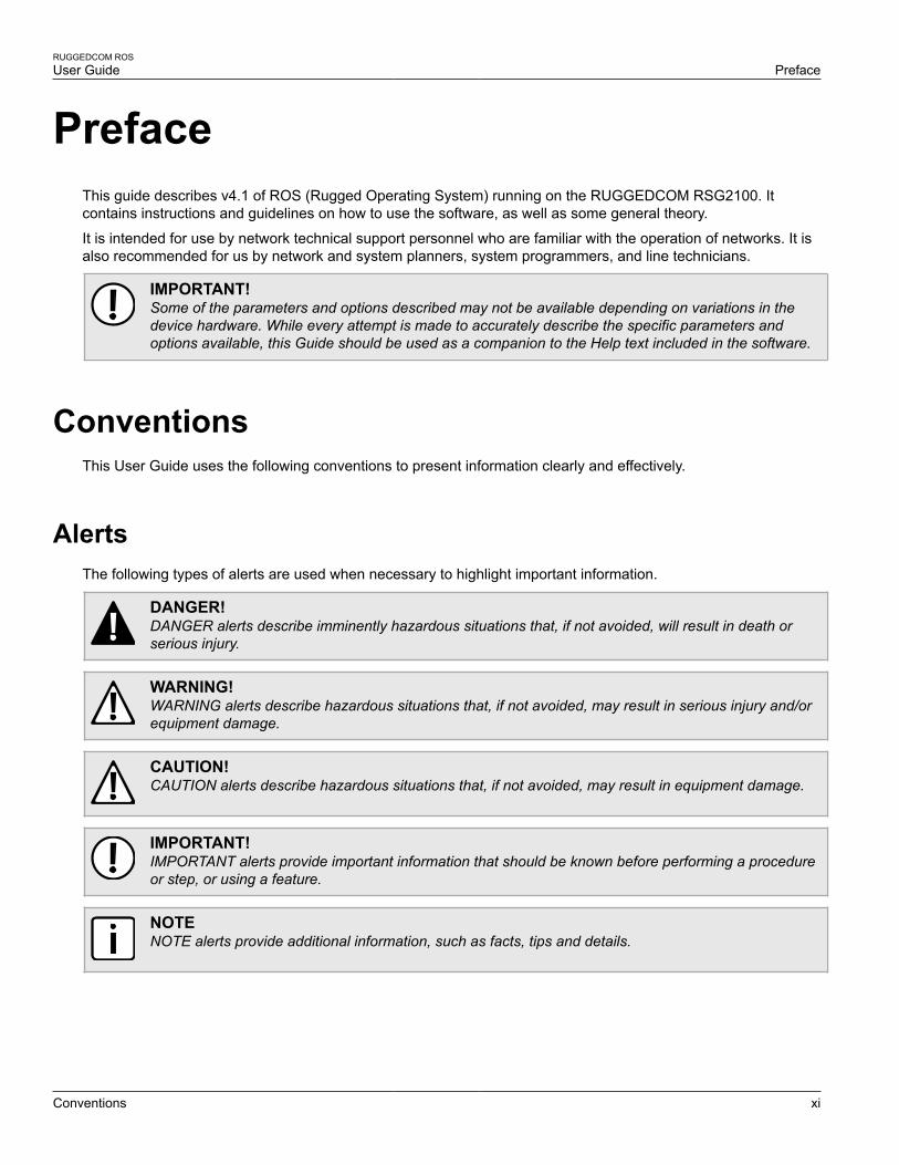
AlertsThe following types of alerts are used when necessary to highlight important information.
DANGER!DANGER alerts describe imminently hazardous situations that, if not avoided, will result in death orserious injury.
WARNING!WARNING alerts describe hazardous situations that, if not avoided, may result in serious injury and/orequipment damage.
CAUTION!CAUTION alerts describe hazardous situations that, if not avoided, may result in equipment damage.
IMPORTANT!IMPORTANT alerts provide important information that should be known before performing a procedureor step, or using a feature.
NOTENOTE alerts provide additional information, such as facts, tips and details.
Preface
RUGGEDCOM ROSUser Guide
xii CLI Command Syntax
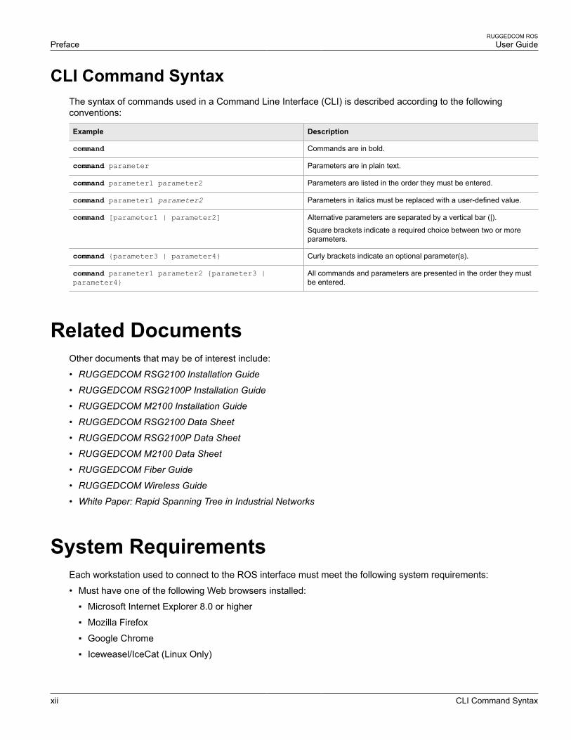
CLI Command SyntaxThe syntax of commands used in a Command Line Interface (CLI) is described according to the followingconventions:
Example Description
command Commands are in bold.
command parameter Parameters are in plain text.
command parameter1 parameter2 Parameters are listed in the order they must be entered.
command parameter1 parameter2 Parameters in italics must be replaced with a user-defined value.
command [parameter1 | parameter2] Alternative parameters are separated by a vertical bar (|).
Square brackets indicate a required choice between two or moreparameters.
command {parameter3 | parameter4} Curly brackets indicate an optional parameter(s).
command parameter1 parameter2 {parameter3 |parameter4}
All commands and parameters are presented in the order they mustbe entered.
Related DocumentsOther documents that may be of interest include:
• RUGGEDCOM RSG2100 Installation Guide
• RUGGEDCOM RSG2100P Installation Guide
• RUGGEDCOM M2100 Installation Guide
• RUGGEDCOM RSG2100 Data Sheet
• RUGGEDCOM RSG2100P Data Sheet
• RUGGEDCOM M2100 Data Sheet
• RUGGEDCOM Fiber Guide
• RUGGEDCOM Wireless Guide
• White Paper: Rapid Spanning Tree in Industrial Networks
System RequirementsEach workstation used to connect to the ROS interface must meet the following system requirements:
• Must have one of the following Web browsers installed:
▪ Microsoft Internet Explorer 8.0 or higher
▪ Mozilla Firefox
▪ Google Chrome
▪ Iceweasel/IceCat (Linux Only)
RUGGEDCOM ROSUser Guide
Preface
Accessing Documentation xiii
• Must have a working Ethernet interface compatible with at least one of the port types on the RUGGEDCOMdevice
• The ability to configure an IP address and netmask on the computer’s Ethernet interface
Accessing DocumentationThe latest Hardware Installation Guides and Software User Guides for most RUGGEDCOM products areavailable online at www.siemens.com/ruggedcom.
For any questions about the documentation or for assistance finding a specific document, contact a Siemenssales representative.
TrainingSiemens offers a wide range of educational services ranging from in-house training of standard courses onnetworking, Ethernet switches and routers, to on-site customized courses tailored to the customer's needs,experience and application.
Siemens' Educational Services team thrives on providing our customers with the essential practical skills to makesure users have the right knowledge and expertise to understand the various technologies associated with criticalcommunications network infrastructure technologies.
Siemens' unique mix of IT/Telecommunications expertise combined with domain knowledge in the utility,transportation and industrial markets, allows Siemens to provide training specific to the customer's application.
For more information about training services and course availability, visit www.siemens.com/ruggedcom orcontact a Siemens sales representative.
Customer SupportCustomer support is available 24 hours, 7 days a week for all Siemens customers. For technical support orgeneral information, contact Siemens Customer Support through any of the following methods:
• OnlineVisit http://www.siemens.com/automation/support-request to submit a Support Request (SR) or check on thestatus of an existing SR.
• TelephoneCall a local hotline center to submit a Support Request (SR). To locate a local hotline center, visit http://www.automation.siemens.com/mcms/aspa-db/en/automation-technology/Pages/default.aspx.
• Mobile AppInstall the Industry Online Support app by Siemens AG on any Android, Apple iOS or Windows mobile deviceand be able to:
▪ Access Siemens' extensive library of support documentation, including FAQs, manuals, and much more
▪ Submit SRs or check on the status of an existing SR
▪ Find and contact a local contact person

Preface
RUGGEDCOM ROSUser Guide
xiv Customer Support
▪ Ask questions or share knowledge with fellow Siemens customers and the support community
▪ And much more...
RUGGEDCOM ROSUser Guide
Chapter 1Introduction
Overview 1
IntroductionThis chapter provides a basic overview of the ROS software. It describes the following topics:
• Section 1.1, “Overview”
• Section 1.2, “Security Recommendations and Considerations”
• Section 1.3, “Port Numbering Scheme”
• Section 1.4, “Available Services by Port”
• Section 1.5, “SNMP Management Interface Base (MIB) Support”
• Section 1.6, “SNMP Traps”
• Section 1.7, “ModBus Management Support”
• Section 1.8, “Certificate and Key Requirements”
Section 1.1
OverviewWelcome to the ROS Software User Guide for the RSG2100. This Guide describes the wide array of carriergrade features made available by ROS (Rugged Operating System). These features include:
IMPORTANT!The RSG2100/RSG2100P/M2100 is not intended for use or resale as online control equipment inhazardous, high-risk environments that require fail-safe performance, such as nuclear facilities, aircraftnavigation or communication systems, air traffic control, direct life support machines or weaponssystems, in which the failure of the software could result in death, personal injury, or severe physical orenvironmental damage.
Rugged Operating System (ROS) Features
• Simple plug and play operation - automatic learning,negotiation and crossover detection
• MSTP 802.1Q-2005 (formerly 802.1s)• RSTP (802.1w) and Enhanced Rapid Spanning Tree
(eRSTP™) network fault recovery (<5ms)• Quality of Service (802.1p) for real-time traffic• VLAN (802.1Q) with double tagging and GVRP
support• Link aggregation (802.3ad)• IGMP Snooping for multicast filtering• Port rate limiting and broadcast storm limiting• Port configuration, status, statistics, mirroring,
security• SNTP time synchronization (client and server)
Cyber Security Features
• Muti-level user passwords• SSH/SSL (128-bit encryption)• Enable/disable ports, MAC based port security• Port-based network access control (802.1X)• VLAN (802.1Q) to segregate and secure network
traffic• RADIUS centralized password management• SNMPv3 authentication and 56-bit encryption
Management Features
• Web-based, Telnet, CLI management interfaces• SNMP v1/v2/v3 (56-bit encryption)• Remote Monitoring (RMON)• Rich set of diagnostics with logging and alarms
Chapter 1Introduction
RUGGEDCOM ROSUser Guide
2 Security Recommendations and Considerations
• Industrial automation features (eg. Modbus)
Section 1.2
Security Recommendations and ConsiderationsThe following describes important security-related recommendations and suggestions that should be consideredbefore implementing the RSG2100 on any network:
• Section 1.2.1, “Security Recommendations”
• Section 1.2.2, “Key Files”
Section 1.2.1
Security RecommendationsTo prevent unauthorized access to the device, note the following security recommendations:
• Do not connect the device to the Internet. Deploy the device only within a secure network perimeter.
• Replace the default passwords for all user accounts and processes (where applicable) before the device isdeployed.
• Use strong passwords. Avoid weak passwords such as password1, 123456789, abcdefgh, etc. For moreinformation about creating strong passwords, refer to the password requirements in Section 4.3, “ConfiguringPasswords”.
• Make sure passwords are protected and not shared with unauthorized personnel.
• Passwords should not be re-used across different usernames and systems, or after they expire.
• When RADIUS authentication is done remotely, make sure all communications are within the security perimeteror on a secure channel.
• SSL and SSH keys are accessible to users who connect to the device via the serial console. Make sure to takeappropriate precautions when shipping the device beyond the boundaries of the trusted environment:
▪ Replace the SSH and SSL keys with throwaway keys prior to shipping.
▪ Take the existing SSH and SSL keys out of service. When the device returns, create and program new keysfor the device.
• Restrict physical access to the device to only trusted personnel. A person with malicious intent could extractcritical information, such as certificates, keys, etc. (user passwords are protected by hash codes), or reprogramthe device.
• Control access to the serial console to the same degree as any physical access to the device. Access to theserial console allows for potential access to the ROS boot loader, which includes tools that may be used to gaincomplete access to the device.
• Only enable services that will be used on the device, including physical ports. Unused physical ports couldpotentially be used to gain access to the network behind the device.
• If SNMP is enabled, limit the number of IP addresses that can connect to the device and change thecommunity names. Also configure SNMP to raise a trap upon authentication failures. For more information,refer to Section 5.7, “Managing SNMP”.
• Avoid using insecure services such as Telnet and TFTP, or disable them completely if possible. These servicesare available for historical reasons and are disabled by default.
RUGGEDCOM ROSUser Guide
Chapter 1Introduction
Key Files 3
• Limit the number of simultaneous Web Server, Telnet and SSH sessions allowed.
• Configure remote system logging to forward all logs to a central location. For more information, refer toSection 3.5, “Managing Logs”.
• Configuration files are provided in the CSV (comma separated values) format for ease of use. Make sureconfiguration files are properly protected when they exist outside of the device. For instance, encrypt the files,store them in a secure place, and do not transfer them via insecure communication channels.
• Management of the configuration file, certificates and keys is the responsibility of the device owner. Beforereturning the device to Siemens for repair, make sure encryption is disabled (to create a cleartext version of theconfiguration file) and replace the current certificates and keys with temporary throwaway certificates and keysthat can be destroyed upon the device's return.
• Be aware of any non-secure protocols enabled on the device. While some protocols, such as HTTPS andSSH, are secure, others, such as Telnet and RSH, were not designed for this purpose. Appropriate safeguardsagainst non-secure protocols should be taken to prevent unauthorized access to the device/network.
• Configure port security features on access ports to prevent a third-party from launching various attacks that canharm the network or device. For more information, refer to Section 5.10, “Managing Port Security”.
• Periodically audit the device to make sure it complies with these recommendations and/or any internal securitypolicies.
Section 1.2.2
Key FilesROS uses security keys to establish secure remote logins (SSH) and Web access (SSL).
It is strongly recommended that a unique SSL certificate and SSH keys be created and provisioned. New ROS -based units from Siemens will be shipped with a unique certificate and keys preconfigured in the ssl.crt andssh.keys flash files.
The default and auto-generated SSL certificates are self-signed. It is recommended to use an SSL certificate thatis either signed by a trusted third-party Certificate Authority (CA) or by an organization's own CA. This techniqueis described in the Siemens application note: Creating/Uploading SSH Keys and SSL Certificates to ROS UsingWindows, available from www.siemens.com/ruggedcom.
The sequence of events related to Key Management during an upgrade to ROS v4.1 or later is as follows:
NOTEThe auto-generation of SSH keys is not available for Non-Controlled (NC) versions of ROS.
• On first boot, ROS will start the SSH and SSL services using the default keys.
• Immediately after boot, ROS will start to generate a unique SSL certificate and SSH key pair, and save eachone to its corresponding flash file. This process may take several minutes to complete. As each one is created,the corresponding service is immediately restarted with the new keys.
• At any time during the key generation process, custom keys can be uploaded. The custom keys will takeprecedence over both the default and auto-generated keys.
• On subsequent boot, if there is a valid ssl.crt file, the default certificate will not be used for SSL. If there is avalid ssh.keys file, the default SSH key will not be used.
• At any time, new keys may be uploaded or generated by ROS using the sslkeygen or sshkeygen CLIcommands.
The following sections describe SSL certificates and SSH key pairs in more detail:

Chapter 1Introduction
RUGGEDCOM ROSUser Guide
4 SSL Certificates
• Section 1.2.2.1, “SSL Certificates”
• Section 1.2.2.2, “SSH Key Pairs”
Section 1.2.2.1
SSL CertificatesROS supports SSL certificates that conform to the following specifications:
• X.509 v3 digital certificate format
• PEM format
• RSA key pair, 512 to 2048 bits
The RSA key pair used in the default certificate and in those generated by ROS uses a public key of 1024 bits inlength.
NOTERSA keys smaller than 1024 bits in length are not recommended. Support is only included here forcompatibility with legacy equipment.
NOTEThe default certificate and keys are common to all ROS versions without a certificate or key files. Thatis why it is important to either allow the key auto-generation to complete or to provision custom keys. Inthis way, one has at least unique, and at best, traceable and verifiable keys installed when establishingsecure communication with the unit.
NOTERSA key generation times increase depending on the key length. 1024 bit RSA keys may take severalminutes to generate, whereas 2048 bit keys may take significantly longer. A typical modern PC system,however, can generate these keys in seconds.
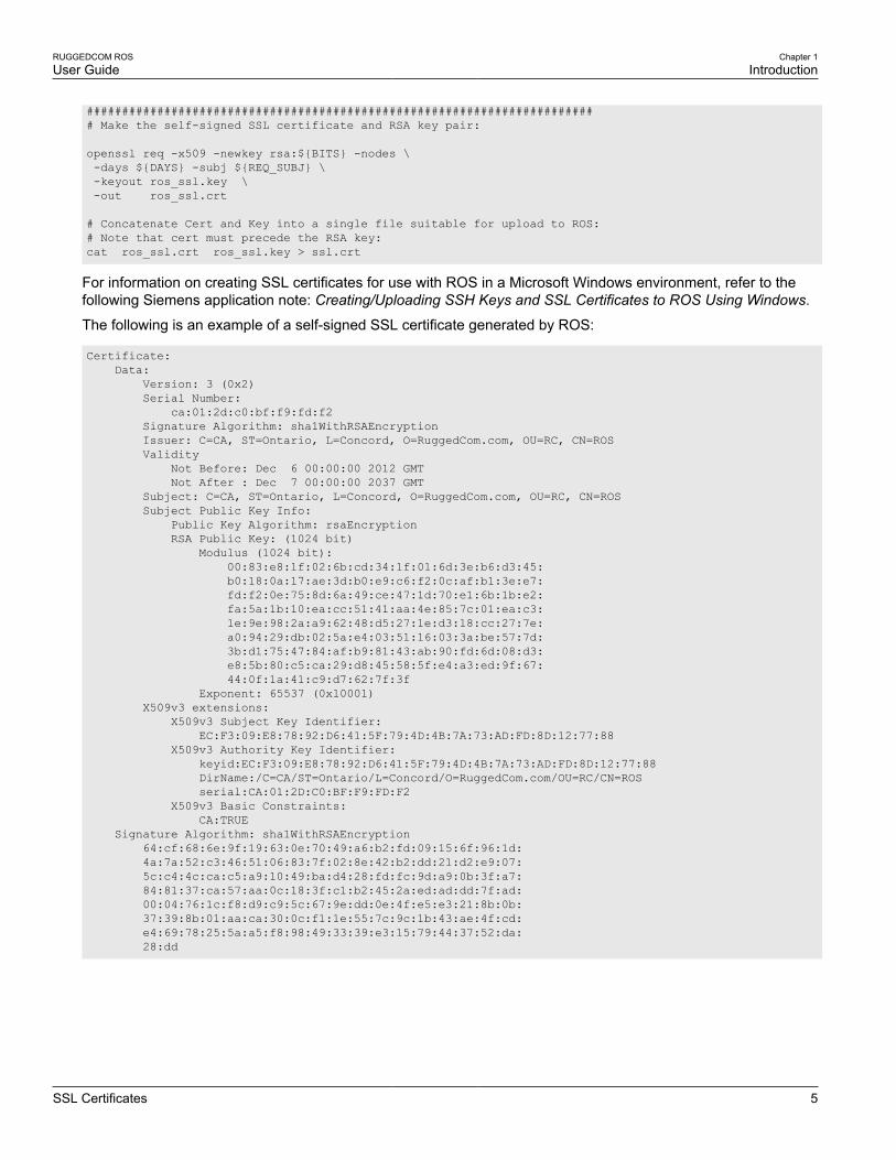
The following (bash) shell script fragment uses the openssl command line utility to generate a self-signedX.509 v3 SSL certificate with a 1024 bit RSA key suitable for use in ROS . Note that two standard PEM files arerequired: the SSL certificate and the RSA private key file. These are concatenated into the resulting ssl.crt file,which may then be uploaded to ROS:
# RSA key size:BITS=1024# 20 years validity:DAYS=7305
# Values that will be stored in the Distinguished Name fields:
COUNTRY_NAME=CA # Two-letter country codeSTATE_OR_PROVINCE_NAME=Ontario # State or ProvinceLOCALITY_NAME=Concord # CityORGANIZATION=Ruggedcom.com # Your organization's nameORGANIZATION_CA=${ORGANIZATION}_CA # Your Certificate AuthorityCOMMON_NAME=RC # The DNS or IP address of the ROS unitORGANIZATIONAL_UNIT=ROS # Organizational unit name
# Variables used in the construction of the certificateREQ_SUBJ="/C=${COUNTRY_NAME}/ST=${STATE_OR_PROVINCE_NAME}/L=${LOCALITY_NAME}/O=${ORGANIZATION}/OU=${ORGANIZATIONAL_UNIT}/CN=${COMMON_NAME}/"REQ_SUBJ_CA="/C=${COUNTRY_NAME}/ST=${STATE_OR_PROVINCE_NAME}/L=${LOCALITY_NAME}/O=${ORGANIZATION_CA}/OU=${ORGANIZATIONAL_UNIT}/"
RUGGEDCOM ROSUser Guide
Chapter 1Introduction
SSL Certificates 5
######################################################################### Make the self-signed SSL certificate and RSA key pair:
openssl req -x509 -newkey rsa:${BITS} -nodes \ -days ${DAYS} -subj ${REQ_SUBJ} \ -keyout ros_ssl.key \ -out ros_ssl.crt
# Concatenate Cert and Key into a single file suitable for upload to ROS:# Note that cert must precede the RSA key:cat ros_ssl.crt ros_ssl.key > ssl.crt
For information on creating SSL certificates for use with ROS in a Microsoft Windows environment, refer to thefollowing Siemens application note: Creating/Uploading SSH Keys and SSL Certificates to ROS Using Windows.
The following is an example of a self-signed SSL certificate generated by ROS:
Certificate: Data: Version: 3 (0x2) Serial Number: ca:01:2d:c0:bf:f9:fd:f2 Signature Algorithm: sha1WithRSAEncryption Issuer: C=CA, ST=Ontario, L=Concord, O=RuggedCom.com, OU=RC, CN=ROS Validity Not Before: Dec 6 00:00:00 2012 GMT Not After : Dec 7 00:00:00 2037 GMT Subject: C=CA, ST=Ontario, L=Concord, O=RuggedCom.com, OU=RC, CN=ROS Subject Public Key Info: Public Key Algorithm: rsaEncryption RSA Public Key: (1024 bit) Modulus (1024 bit): 00:83:e8:1f:02:6b:cd:34:1f:01:6d:3e:b6:d3:45: b0:18:0a:17:ae:3d:b0:e9:c6:f2:0c:af:b1:3e:e7: fd:f2:0e:75:8d:6a:49:ce:47:1d:70:e1:6b:1b:e2: fa:5a:1b:10:ea:cc:51:41:aa:4e:85:7c:01:ea:c3: 1e:9e:98:2a:a9:62:48:d5:27:1e:d3:18:cc:27:7e: a0:94:29:db:02:5a:e4:03:51:16:03:3a:be:57:7d: 3b:d1:75:47:84:af:b9:81:43:ab:90:fd:6d:08:d3: e8:5b:80:c5:ca:29:d8:45:58:5f:e4:a3:ed:9f:67: 44:0f:1a:41:c9:d7:62:7f:3f Exponent: 65537 (0x10001) X509v3 extensions: X509v3 Subject Key Identifier: EC:F3:09:E8:78:92:D6:41:5F:79:4D:4B:7A:73:AD:FD:8D:12:77:88 X509v3 Authority Key Identifier: keyid:EC:F3:09:E8:78:92:D6:41:5F:79:4D:4B:7A:73:AD:FD:8D:12:77:88 DirName:/C=CA/ST=Ontario/L=Concord/O=RuggedCom.com/OU=RC/CN=ROS serial:CA:01:2D:C0:BF:F9:FD:F2 X509v3 Basic Constraints: CA:TRUE Signature Algorithm: sha1WithRSAEncryption 64:cf:68:6e:9f:19:63:0e:70:49:a6:b2:fd:09:15:6f:96:1d: 4a:7a:52:c3:46:51:06:83:7f:02:8e:42:b2:dd:21:d2:e9:07: 5c:c4:4c:ca:c5:a9:10:49:ba:d4:28:fd:fc:9d:a9:0b:3f:a7: 84:81:37:ca:57:aa:0c:18:3f:c1:b2:45:2a:ed:ad:dd:7f:ad: 00:04:76:1c:f8:d9:c9:5c:67:9e:dd:0e:4f:e5:e3:21:8b:0b: 37:39:8b:01:aa:ca:30:0c:f1:1e:55:7c:9c:1b:43:ae:4f:cd: e4:69:78:25:5a:a5:f8:98:49:33:39:e3:15:79:44:37:52:da: 28:dd
Chapter 1Introduction
RUGGEDCOM ROSUser Guide
6 SSH Key Pairs
Section 1.2.2.2
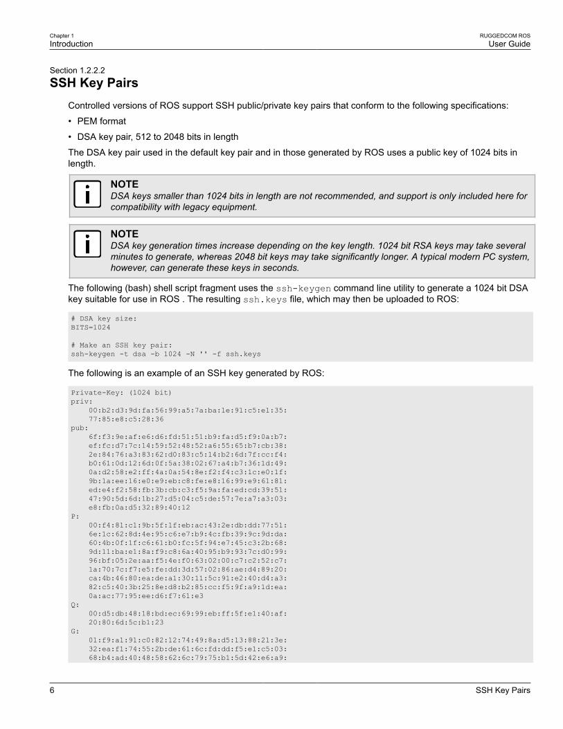
SSH Key PairsControlled versions of ROS support SSH public/private key pairs that conform to the following specifications:
• PEM format
• DSA key pair, 512 to 2048 bits in length
The DSA key pair used in the default key pair and in those generated by ROS uses a public key of 1024 bits inlength.
NOTEDSA keys smaller than 1024 bits in length are not recommended, and support is only included here forcompatibility with legacy equipment.
NOTEDSA key generation times increase depending on the key length. 1024 bit RSA keys may take severalminutes to generate, whereas 2048 bit keys may take significantly longer. A typical modern PC system,however, can generate these keys in seconds.
The following (bash) shell script fragment uses the ssh-keygen command line utility to generate a 1024 bit DSAkey suitable for use in ROS . The resulting ssh.keys file, which may then be uploaded to ROS:
# DSA key size:BITS=1024
# Make an SSH key pair:ssh-keygen -t dsa -b 1024 -N '' -f ssh.keys
The following is an example of an SSH key generated by ROS:
Private-Key: (1024 bit)priv: 00:b2:d3:9d:fa:56:99:a5:7a:ba:1e:91:c5:e1:35: 77:85:e8:c5:28:36pub: 6f:f3:9e:af:e6:d6:fd:51:51:b9:fa:d5:f9:0a:b7: ef:fc:d7:7c:14:59:52:48:52:a6:55:65:b7:cb:38: 2e:84:76:a3:83:62:d0:83:c5:14:b2:6d:7f:cc:f4: b0:61:0d:12:6d:0f:5a:38:02:67:a4:b7:36:1d:49: 0a:d2:58:e2:ff:4a:0a:54:8e:f2:f4:c3:1c:e0:1f: 9b:1a:ee:16:e0:e9:eb:c8:fe:e8:16:99:e9:61:81: ed:e4:f2:58:fb:3b:cb:c3:f5:9a:fa:ed:cd:39:51: 47:90:5d:6d:1b:27:d5:04:c5:de:57:7e:a7:a3:03: e8:fb:0a:d5:32:89:40:12P: 00:f4:81:c1:9b:5f:1f:eb:ac:43:2e:db:dd:77:51: 6e:1c:62:8d:4e:95:c6:e7:b9:4c:fb:39:9c:9d:da: 60:4b:0f:1f:c6:61:b0:fc:5f:94:e7:45:c3:2b:68: 9d:11:ba:e1:8a:f9:c8:6a:40:95:b9:93:7c:d0:99: 96:bf:05:2e:aa:f5:4e:f0:63:02:00:c7:c2:52:c7: 1a:70:7c:f7:e5:fe:dd:3d:57:02:86:ae:d4:89:20: ca:4b:46:80:ea:de:a1:30:11:5c:91:e2:40:d4:a3: 82:c5:40:3b:25:8e:d8:b2:85:cc:f5:9f:a9:1d:ea: 0a:ac:77:95:ee:d6:f7:61:e3Q: 00:d5:db:48:18:bd:ec:69:99:eb:ff:5f:e1:40:af: 20:80:6d:5c:b1:23G: 01:f9:a1:91:c0:82:12:74:49:8a:d5:13:88:21:3e: 32:ea:f1:74:55:2b:de:61:6c:fd:dd:f5:e1:c5:03: 68:b4:ad:40:48:58:62:6c:79:75:b1:5d:42:e6:a9:

RUGGEDCOM ROSUser Guide
Chapter 1Introduction
Port Numbering Scheme 7
97:86:37:d8:1e:e5:65:09:28:86:2e:6a:d5:3d:62: 50:06:b8:d3:f9:d4:9c:9c:75:84:5b:db:96:46:13: f0:32:f0:c5:cb:83:01:a8:ae:d1:5a:ac:68:fb:49: f9:b6:8b:d9:d6:0d:a7:de:ad:16:2b:23:ff:8e:f9: 3c:41:16:04:66:cf:e8:64:9e:e6:42:9a:d5:97:60: c2:e8:9e:f4:bc:8f:6f:e0
Section 1.3
Port Numbering SchemeFor quick identification, each port on an RSG2100/RSG2100P/M2100 device is assigned a number. All portnumbers are silk-screened on the device.
2
1
4
3
6
5
8
7
10
9
12
11
14
13
16
15
18
17
20
19
Figure 1: RSG2100/RSG2100P/M2100 Port Numbering (Typical)
Use these numbers to configure applicable features on select ports.
Section 1.4
Available Services by PortThe following table lists the services available under ROS. This table includes the following information:
• ServicesThe service supported by the device.
• Port NumberThe port number associated with the service.
• Port OpenThe port state, whether it is always open and cannot be closed, or open only, but can be configured.
NOTEIn certain cases, the service might be disabled, but the port can still be open (e.g. TFTP).
• Port DefaultThe default state of the port (i.e. open or closed).
• Access Authorized

Chapter 1Introduction
RUGGEDCOM ROSUser Guide
8 Available Services by Port
Denotes whether the ports/services are authenticated during access.
Services Port Number Port Open Port Default AccessAuthorized Note
Telnet TCP/23 Open(configurable)
Closed Yes Only availablethrough twomanagementinterfaces.
HTTP TCP/80 Open, redirectsto 443
Open —
HTTPS TCP/443 Open Open Yes
RSH TCP/512 Open(configurable)
Closed Yes Only availablethrough twomanagementinterfaces.
TFTP UDP/69 Open(configurable)
Closed No Only availablethrough twomanagementinterfaces.
SFTP TCP/22 Open Open Yes Only availablethrough twomanagementinterfaces.
SNMP UDP/161 Open(configurable)
Closed Yes Only availablethrough twomanagementinterfaces.
SNTP UDP/123 Open - Alwaysmight acts asserver
Open No Only availablethrough twomanagementinterfaces.
SSH TCP/22 Open Open Yes Only availablethrough twomanagementinterfaces.
ICMP — Open Open No
TACACS+ TCP/49(configurable)
Open(configurable)
Closed Yes
RADIUS UDP/1812to send(configurable),opens randomport to listen to
Open(configurable)
Closed Yes Only availablethrough twomanagementinterfaces.
Remote Syslog UDP/514(configurable)
Open(configurable)
Closed No Only availablethrough twomanagementinterfaces.
TCP Modbus (Server) TCP/502 Open Open No Only availablethrough twomanagementinterfaces.
TCP Modbus (Switch) TCP/502 Open(configurable)
Closed No

RUGGEDCOM ROSUser Guide
Chapter 1Introduction
SNMP Management Interface Base (MIB) Support 9
Services Port Number Port Open Port Default AccessAuthorized Note
DHCP, DHCP Agent UDP/67 sendingmsg if enabled - ifreceived, alwayscome to CPU,dropped if servicenot configured
Open Open No
RCDP — Open(configurable)
Closed Yes
Section 1.5
SNMP Management Interface Base (MIB) SupportROS supports a variety of standard MIBs, proprietary RUGGEDCOM MIBs and Agent Capabilities MIBs, all forSNMP (Simple Network Management Protocol).
• Section 1.5.1, “Supported Standard MIBs”
• Section 1.5.2, “Supported Proprietary RUGGEDCOM MIBs”
• Section 1.5.3, “Supported Agent Capabilities”
Section 1.5.1
Supported Standard MIBsROS supports the following standard MIBs:
Standard MIB Name Title
RFC 2578 SNMPv2-SMI Structure of Management Information Version 2
RFC 2579 SNMPv2-TC Textual Convention s for SMIv2
SNMPv2-CONF Conformance Statements for SMIv2RFC 2580
IANAifType Enumerated Values of the ifType Object Defined ifTable defined inIF-MIB
RFC 1907 SNMPv2-MIB Management Information Base for SNMPv2
RFC 2011 IP-MIB SNMPv2 Mnagement Information Base for Internet Protocol usingSMIv2
RFC 2012 TCP-MIB SNMPv2 Management Information Base for the TransmissionControl Protocol using SMIv2
RFC 2013 UDP-MIB Management Information Base for the UDP using SMIv2
RFC 1659 RS-232-MIB Definitions of Managed Objects for RS-232-like Hardware Devices
RFC 2863 IF-MIB The Interface Group MIB
RFC 2819 RMON-MIB Remote Network Monitoring (RMON) management Information base
RFC 4188 BRIDGE-MIB Definitions of Managed Objects for Bridges

Chapter 1Introduction
RUGGEDCOM ROSUser Guide
10 Supported Proprietary RUGGEDCOM MIBs
Standard MIB Name Title
RFC 4318 RSTP-MIB Definitions of Managed Objects for Bridges with Rapid SpanningTree Protocol
RFC 3411 SNMP-FRAMEWORK-MIB An Architecture for Describing Simple Network ManagementProtocol (SNMP) Management Framework
RFC 3414 SNMP-USER-BASED-SM-MIB User-based Security Model (USM) for Version 3 of the SimpleNetwork Management Protocol (SNMPv3)
RFC 3415 SNMP-VIEW-BASED-ACM-MIB View-bsed Access Control Model (VACM) for the SimpleManagement Protocol (SNMP)
IEEE 802.3ad IEEE8023-LAG-MIB Management Information Base Module for Link Aggregation
IEEE 802.1AB-2005 LLDP-MIB Management Information Base Module for LLDP Configuration,Statistics, Local System Data and Remote Systems DataComponents
RFC 4363 Q-BRIDGE-MIB Definitions of Managed Objects for Bridges with Traffic Classes,Multicast Filtering, and Virtual LAN Extensions
Section 1.5.2
Supported Proprietary RUGGEDCOM MIBsROS supports the following proprietary RUGGEDCOM MIBs:
File Name MIB Name Description
ruggedcom.mib RUGGEDCOM-MIB RUGGEDCOM enterprise SMI
ruggedcomtraps.mib RUGGEDCOM-TRAPS-MIB RUGGEDCOM traps definition
rcsysinfo.mib RUGGEDCOM-SYS-INFO-MIB General system information aboutRUGGEDCOM device
rcDot11.mib RUGGEDCOM-DOT11-MIB Managemet for wireless interface onRUGGEDCOM device
rcPoe.mib RUGGEDCOM-POE-MIB Management for PoE ports onRUGGEDCOM device
rcSerial.mib RUGGEDCOM-SERIAL-MIB Managemet for seral ports onRUGGEDCOM device
rcRstp.mib RUGGEDCOM-STP-MIB Management for RSTP protocol
Section 1.5.3
Supported Agent CapabilitiesROS supports the following agent capabilities for the SNMP agent:
NOTEFor information about agent capabilities for SNMPv2, refer to RFC 2580 [http://tools.ietf.org/html/rfc2580].

RUGGEDCOM ROSUser Guide
Chapter 1Introduction
SNMP Traps 11
File Name MIB Name Supported MIB
rcsnmpv2AC.mib RC-SNMPv2-MIB-AC SNMPv2-MIB
rcudpmibAC.mib RC-UDP-MIB-AC UDP-MIB
rctcpmibAC.mib RC-TCP-MIB-AC TCP-MIB
rcSnmpUserBasedSmMibAC.mib RC-SNMP-USER-BASED-SM-MIB-AC SNMP-USER-BASED-SM-MIB-AC
rcSnmpViewBasedAcmMibAC.mib RC-SNMP-VIEW-BASED-ACM-MIB-AC SNMP-VIEW-BASED-ACM-MIB-AC
rcifmibAC.mib RC-IF-MIB-AC IF-MIB
rcbridgemibAC.mib RC-BRIDGE-MIB-AC BRIDGE-MIB
rcrmonmibAC.mib RC-RMON-MIB-AC RMON-MIB
rcqbridgemibAC.mib RC-Q-BRIDGE-MIB-AC Q-BRIDGE-MIB
rcipmibAC.mib RC-IP-MIB-AC IP-MIB
rclldpmibAC.mib RC-LLDP-MIB-AC LLDP-MIB
rclagmibAC.mib RC-LAG-MIB-AC IEEE8023-LAG-MIB
rcrstpmibAC.mib RC_RSTP-MIB-AC RSTP-MIB
rcrcdot11AC.mib RC-RUGGEDCOM-DOT11-MIB-AC RUGGEDCOM-DOT11- MIB
rcrcpoeAC.mib RC-RUGGEDCOM-POE-MIB-AC RUGGEDCOM-POE-MIB
rcrcrstpmibAC.mib RC-RUGGEDCOM-STP-AC-MIB RUGGEDCOM-STP-MIB
rcrcsysinfomibAC.mib RC-RUGGEDCOM-SYS-INFO-MIB-AC RUGGEDCOM-SYS-INFO-MIB
rcrctrapsmibAC.mib RC-RUGGEDCOM-TRAPS-MIB-AC RUGGEDCOM-TRAPS-MIB
rcrs232mibAC.mib RUGGEDCOM_RS-232-MIB-AC RS-232-MIB
rcserialmibAC.mib RC-RUGGEDCOM-SERIAL-MIB-AC RUGGEDCOM-SERIAL-MIB
Section 1.6
SNMP TrapsThe device generates the following standard traps:
Table: Standard Traps
Trap MIB
linkDown
linkUp
IF-MIB
authenticationFailure
coldStart
SNMPv2-MIB
newRoot
topologyChage
BRIDGE-MIB
risingAlarm RMON-MIB

Chapter 1Introduction
RUGGEDCOM ROSUser Guide
12 SNMP Traps
Trap MIB
fallingAlarm
lldpRemoteTablesChange LLDP-MIB
The device also generates the following proprietary traps:
Table: Proprietary Traps
Trap MIB
genericTrap
powerSupplyTrap
swUpgradeTrap
cfgChangeTrap
weakPasswordTrap
defaultKeysTrap
RUGGEDCOM-TRAPS-MIB
Generic traps carry information about events in their severity and description objects. They are sent at the sametime an alarm is generated for the device. The following are examples of RUGGEDCOM generic traps:
NOTEInformation about generic traps can be retrieved using the CLI command alarms. For moreinformation about the alarms command, refer to Section 2.6.1, “Available CLI Commands”.
Table: Generic Traps
Trap Severity
heap error Alert
NTP server failure notification
real time clock failure Error
failed password Warning
MAC address not learned by switch fabric Warning
BootP client: TFTP transfer failure Error
received looped back BPDU Error
received two consecutive confusing BPDUs on port, forcing down Error
GVRP failed to learn – too many VLANs Warning
The device generates the following traps when specific events occur:
Table: Event-Based Traps
Trap MIB Event
rcRstpNewTopology RUGGEDCOM-STP-MIB This trap is generated when the devicetopology becomes stable after a topologychange occurs on a switch port.

RUGGEDCOM ROSUser Guide
Chapter 1Introduction
ModBus Management Support 13
Section 1.7
ModBus Management SupportModbus management support in RUGGEDCOM devices provides a simple interface for retrieving basic statusinformation. ModBus support simplifies the job of SCADA (Supervisory Control and Data Acquisition) systemintegrators by providing familiar protocols for retrieving RUGGEDCOM device information. ModBus providesmostly read-only status information, but there are some writable registers for operator commands.
The ModBus protocol PDU (Protocol Data Unit) format is as follows:
Function Code Data
The following sections describe the support for ModBus management:
• Section 1.7.1, “ModBus Function Codes”
• Section 1.7.2, “ModBus Memory Map”
• Section 1.7.3, “ModBus Memory Formats”
Section 1.7.1
ModBus Function CodesRUGGEDCOM devices support the following ModBus function codes for device management through ModBus:
NOTEWhile RUGGEDCOM devices have a variable number of ports, not all registers and bits apply to allproducts.
Registers that are not applicable to a particular device return a zero (0) value. For example, registersreferring to serial ports are not applicable to RUGGEDCOM switch devices.
Read Input Registers or Read Holding Registers — 0x04 or 0x03Example PDU Request
Function Code 1 Byte 0x04(0x03)
Starting Address 2 Bytes 0x0000 to 0xFFFF (Hexadecimal)
128 to 65535 (Decimal)
Number of Input Registers 2 Bytes Bytes 0x0001 to 0x007D
Example PDU Response
Function Code 1 Byte 0x04(0x03)
Byte Count 1 Byte 2 x Na
Number of Input Registers Na x 2 Bytes
a The number of input registers
Write Multiple Registers — 0x10Example PDU Request
Function Code 1 Byte 0x10
Starting Address 2 Bytes 0x0000 to 0xFFFF

Chapter 1Introduction
RUGGEDCOM ROSUser Guide
14 ModBus Memory Map
Number of Input Registers 2 Bytes Bytes 0x0001 to 0x0079
Byte Count 1 Byte 2 x Nb
Registers Value Nb x 2 Bytes Value of the register
b The number of input registers
Example PDU Response
Function Code 1 Byte 0x10
Starting Address 2 Bytes 0x0000 to 0xFFFF
Number of Registers 2 Bytes 1 to 121 (0x79)
Section 1.7.2
ModBus Memory MapThe following details how ModBus process variable data is mapped.
Product InfoThe following data is mapped to the Productinfo table:
Address #Registers Description (Reference Table in UI) R/W Format
0000 16 Product Identification R Text
0010 32 Firmware Identification R Text
0040 1 Number of Ethernet Ports R Uint16
0041 1 Number of Serial Ports R Uint16
0042 1 Number of Alarms R Uint16
0043 1 Power Supply Status R PSStatusCmd
0044 1 FailSafe Relay Status R TruthValue
0045 1 ErrorAlarm Status R TruthValue
Product Write RegisterThe following data is mapped to various tables:
Address #Registers Description (Reference Table in UI) R/W Format
0080 1 Clear Alarms W Cmd
0081 2 Reset Ethernet Ports W PortCmd
0083 2 Clear Ethernet Statistics W PortCmd
0085 2 Reset Serial Ports W PortCmd
0087 2 Clear Serial Port Statistics W PortCmd
AlarmsThe following data is mapped to the alarms table:

RUGGEDCOM ROSUser Guide
Chapter 1Introduction
ModBus Memory Map 15
Address #Registers Description (Reference Table in UI) R/W Format
0100 64 Alarm 1 R Alarm
0140 64 Alarm 2 R Alarm
0180 64 Alarm 3 R Alarm
01C0 64 Alarm 4 R Alarm
0200 64 Alarm 5 R Alarm
0240 64 Alarm 6 R Alarm
0280 64 Alarm 7 R Alarm
02C0 64 Alarm 8 R Alarm
Ethernet Port StatusThe following data is mapped to the ethPortStats table:
Address #Registers Description (Reference Table in UI) R/W Format
03FE 2 Port Link Status R PortCmd
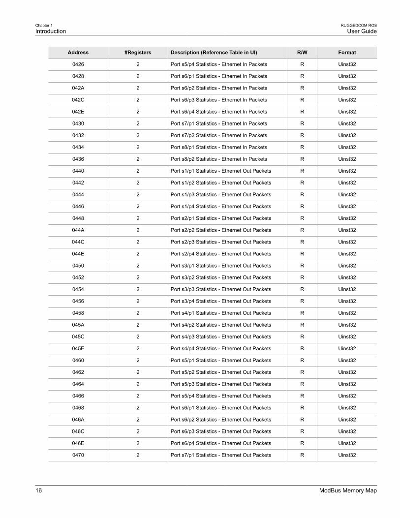
Ethernet StatisticsThe following data is mapped to the rmonStats table:
Address #Registers Description (Reference Table in UI) R/W Format
0400 2 Port s1/p1 Statistics - Ethernet In Packets R Uinst32
0402 2 Port s1/p2 Statistics - Ethernet In Packets R Uinst32
0404 2 Port s1/p3 Statistics - Ethernet In Packets R Uinst32
0406 2 Port s1/p4 Statistics - Ethernet In Packets R Uinst32
0408 2 Port s2/p1 Statistics - Ethernet In Packets R Uinst32
040A 2 Port s2/p2 Statistics - Ethernet In Packets R Uinst32
040C 2 Port s2/p3 Statistics - Ethernet In Packets R Uinst32
040E 2 Port s2/p4 Statistics - Ethernet In Packets R Uinst32
0410 2 Port s3/p1 Statistics - Ethernet In Packets R Uinst32
0412 2 Port s3/p2 Statistics - Ethernet In Packets R Uinst32
0414 2 Port s3/p3 Statistics - Ethernet In Packets R Uinst32
0416 2 Port s3/p4 Statistics - Ethernet In Packets R Uinst32
0418 2 Port s4/p1 Statistics - Ethernet In Packets R Uinst32
041A 2 Port s4/p2 Statistics - Ethernet In Packets R Uinst32
041C 2 Port s4/p3 Statistics - Ethernet In Packets R Uinst32
041E 2 Port s4/p4 Statistics - Ethernet In Packets R Uinst32
0420 2 Port s5/p1 Statistics - Ethernet In Packets R Uinst32
0422 2 Port s5/p2 Statistics - Ethernet In Packets R Uinst32
0424 2 Port s5/p3 Statistics - Ethernet In Packets R Uinst32
Chapter 1Introduction
RUGGEDCOM ROSUser Guide
16 ModBus Memory Map
Address #Registers Description (Reference Table in UI) R/W Format
0426 2 Port s5/p4 Statistics - Ethernet In Packets R Uinst32
0428 2 Port s6/p1 Statistics - Ethernet In Packets R Uinst32
042A 2 Port s6/p2 Statistics - Ethernet In Packets R Uinst32
042C 2 Port s6/p3 Statistics - Ethernet In Packets R Uinst32
042E 2 Port s6/p4 Statistics - Ethernet In Packets R Uinst32
0430 2 Port s7/p1 Statistics - Ethernet In Packets R Uinst32
0432 2 Port s7/p2 Statistics - Ethernet In Packets R Uinst32
0434 2 Port s8/p1 Statistics - Ethernet In Packets R Uinst32
0436 2 Port s8/p2 Statistics - Ethernet In Packets R Uinst32
0440 2 Port s1/p1 Statistics - Ethernet Out Packets R Uinst32
0442 2 Port s1/p2 Statistics - Ethernet Out Packets R Uinst32
0444 2 Port s1/p3 Statistics - Ethernet Out Packets R Uinst32
0446 2 Port s1/p4 Statistics - Ethernet Out Packets R Uinst32
0448 2 Port s2/p1 Statistics - Ethernet Out Packets R Uinst32
044A 2 Port s2/p2 Statistics - Ethernet Out Packets R Uinst32
044C 2 Port s2/p3 Statistics - Ethernet Out Packets R Uinst32
044E 2 Port s2/p4 Statistics - Ethernet Out Packets R Uinst32
0450 2 Port s3/p1 Statistics - Ethernet Out Packets R Uinst32
0452 2 Port s3/p2 Statistics - Ethernet Out Packets R Uinst32
0454 2 Port s3/p3 Statistics - Ethernet Out Packets R Uinst32
0456 2 Port s3/p4 Statistics - Ethernet Out Packets R Uinst32
0458 2 Port s4/p1 Statistics - Ethernet Out Packets R Uinst32
045A 2 Port s4/p2 Statistics - Ethernet Out Packets R Uinst32
045C 2 Port s4/p3 Statistics - Ethernet Out Packets R Uinst32
045E 2 Port s4/p4 Statistics - Ethernet Out Packets R Uinst32
0460 2 Port s5/p1 Statistics - Ethernet Out Packets R Uinst32
0462 2 Port s5/p2 Statistics - Ethernet Out Packets R Uinst32
0464 2 Port s5/p3 Statistics - Ethernet Out Packets R Uinst32
0466 2 Port s5/p4 Statistics - Ethernet Out Packets R Uinst32
0468 2 Port s6/p1 Statistics - Ethernet Out Packets R Uinst32
046A 2 Port s6/p2 Statistics - Ethernet Out Packets R Uinst32
046C 2 Port s6/p3 Statistics - Ethernet Out Packets R Uinst32
046E 2 Port s6/p4 Statistics - Ethernet Out Packets R Uinst32
0470 2 Port s7/p1 Statistics - Ethernet Out Packets R Uinst32

RUGGEDCOM ROSUser Guide
Chapter 1Introduction
ModBus Memory Map 17
Address #Registers Description (Reference Table in UI) R/W Format
0472 2 Port s7/p2 Statistics - Ethernet Out Packets R Uinst32
0474 2 Port s8/p1 Statistics - Ethernet Out Packets R Uinst32
0476 2 Port s8/p2 Statistics - Ethernet Out Packets R Uinst32
0480 2 Port s1/p1 Statistics - Ethernet In Packets R Uinst32
0482 2 Port s1/p2 Statistics - Ethernet In Packets R Uinst32
0484 2 Port s1/p3 Statistics - Ethernet In Packets R Uinst32
0486 2 Port s1/p4 Statistics - Ethernet In Packets R Uinst32
0488 2 Port s2/p1 Statistics - Ethernet In Packets R Uinst32
048A 2 Port s2/p2 Statistics - Ethernet In Packets R Uinst32
048C 2 Port s2/p3 Statistics - Ethernet In Packets R Uinst32
048E 2 Port s2/p4 Statistics - Ethernet In Packets R Uinst32
0490 2 Port s3/p1 Statistics - Ethernet In Packets R Uinst32
0492 2 Port s3/p2 Statistics - Ethernet In Packets R Uinst32
0494 2 Port s3/p3 Statistics - Ethernet In Packets R Uinst32
0496 2 Port s3/p4 Statistics - Ethernet In Packets R Uinst32
0498 2 Port s4/p1 Statistics - Ethernet In Packets R Uinst32
049A 2 Port s4/p2 Statistics - Ethernet In Packets R Uinst32
049C 2 Port s4/p3 Statistics - Ethernet In Packets R Uinst32
049E 2 Port s4/p4 Statistics - Ethernet In Packets R Uinst32
04A0 2 Port s5/p1 Statistics - Ethernet In Packets R Uinst32
04A2 2 Port s5/p2 Statistics - Ethernet In Packets R Uinst32
04A4 2 Port s5/p3 Statistics - Ethernet In Packets R Uinst32
04A6 2 Port s5/p4 Statistics - Ethernet In Packets R Uinst32
04A8 2 Port s6/p1 Statistics - Ethernet In Packets R Uinst32
04AA 2 Port s6/p2 Statistics - Ethernet In Packets R Uinst32
04AC 2 Port s6/p3 Statistics - Ethernet In Packets R Uinst32
04AE 2 Port s6/p4 Statistics - Ethernet In Packets R Uinst32
04B0 2 Port s7/p1 Statistics - Ethernet In Packets R Uinst32
04B2 2 Port s7/p2 Statistics - Ethernet In Packets R Uinst32
04B4 2 Port s8/p1 Statistics - Ethernet In Packets R Uinst32
04B6 2 Port s8/p2 Statistics - Ethernet In Packets R Uinst32
04C0 2 Port s1/p1 Statistics - Ethernet Out Packets R Uinst32
04C2 2 Port s1/p2 Statistics - Ethernet Out Packets R Uinst32
04C4 2 Port s1/p3 Statistics - Ethernet Out Packets R Uinst32
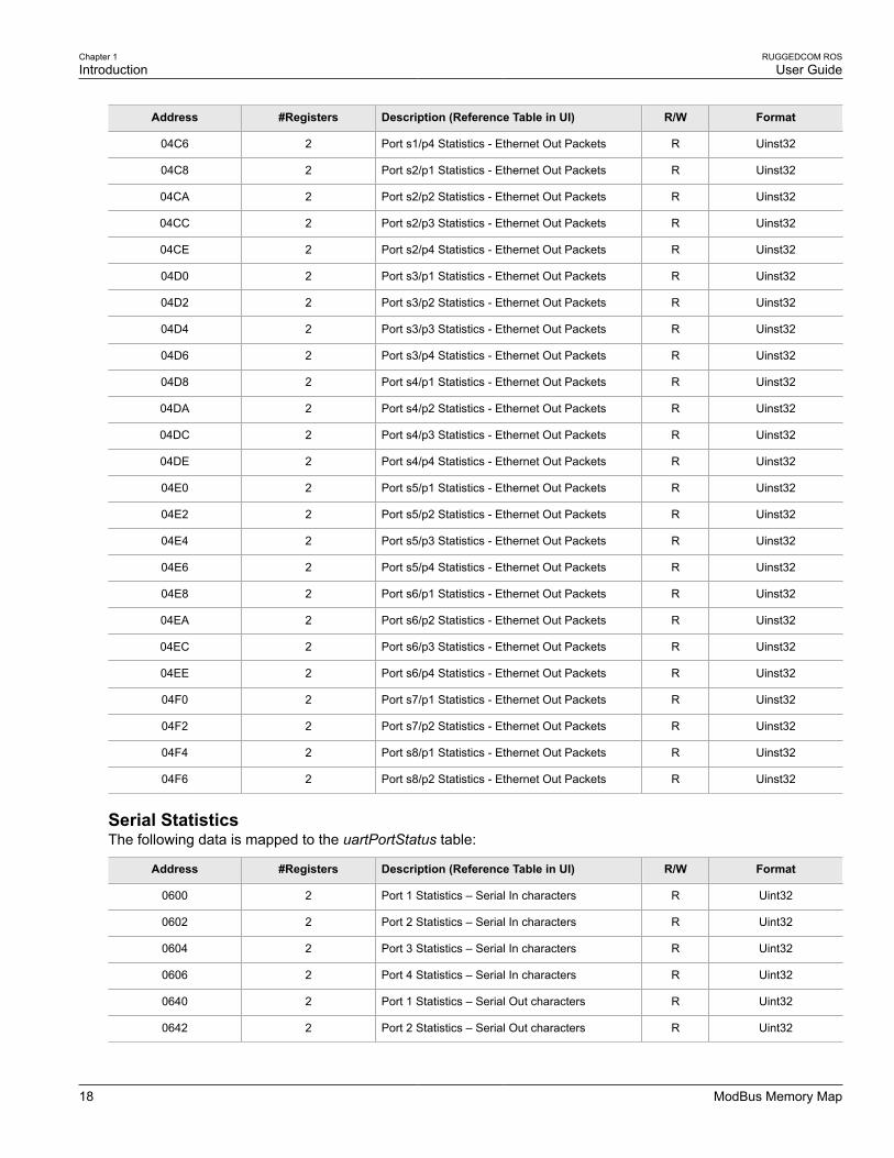
Chapter 1Introduction
RUGGEDCOM ROSUser Guide
18 ModBus Memory Map
Address #Registers Description (Reference Table in UI) R/W Format
04C6 2 Port s1/p4 Statistics - Ethernet Out Packets R Uinst32
04C8 2 Port s2/p1 Statistics - Ethernet Out Packets R Uinst32
04CA 2 Port s2/p2 Statistics - Ethernet Out Packets R Uinst32
04CC 2 Port s2/p3 Statistics - Ethernet Out Packets R Uinst32
04CE 2 Port s2/p4 Statistics - Ethernet Out Packets R Uinst32
04D0 2 Port s3/p1 Statistics - Ethernet Out Packets R Uinst32
04D2 2 Port s3/p2 Statistics - Ethernet Out Packets R Uinst32
04D4 2 Port s3/p3 Statistics - Ethernet Out Packets R Uinst32
04D6 2 Port s3/p4 Statistics - Ethernet Out Packets R Uinst32
04D8 2 Port s4/p1 Statistics - Ethernet Out Packets R Uinst32
04DA 2 Port s4/p2 Statistics - Ethernet Out Packets R Uinst32
04DC 2 Port s4/p3 Statistics - Ethernet Out Packets R Uinst32
04DE 2 Port s4/p4 Statistics - Ethernet Out Packets R Uinst32
04E0 2 Port s5/p1 Statistics - Ethernet Out Packets R Uinst32
04E2 2 Port s5/p2 Statistics - Ethernet Out Packets R Uinst32
04E4 2 Port s5/p3 Statistics - Ethernet Out Packets R Uinst32
04E6 2 Port s5/p4 Statistics - Ethernet Out Packets R Uinst32
04E8 2 Port s6/p1 Statistics - Ethernet Out Packets R Uinst32
04EA 2 Port s6/p2 Statistics - Ethernet Out Packets R Uinst32
04EC 2 Port s6/p3 Statistics - Ethernet Out Packets R Uinst32
04EE 2 Port s6/p4 Statistics - Ethernet Out Packets R Uinst32
04F0 2 Port s7/p1 Statistics - Ethernet Out Packets R Uinst32
04F2 2 Port s7/p2 Statistics - Ethernet Out Packets R Uinst32
04F4 2 Port s8/p1 Statistics - Ethernet Out Packets R Uinst32
04F6 2 Port s8/p2 Statistics - Ethernet Out Packets R Uinst32
Serial StatisticsThe following data is mapped to the uartPortStatus table:
Address #Registers Description (Reference Table in UI) R/W Format
0600 2 Port 1 Statistics – Serial In characters R Uint32
0602 2 Port 2 Statistics – Serial In characters R Uint32
0604 2 Port 3 Statistics – Serial In characters R Uint32
0606 2 Port 4 Statistics – Serial In characters R Uint32
0640 2 Port 1 Statistics – Serial Out characters R Uint32
0642 2 Port 2 Statistics – Serial Out characters R Uint32

RUGGEDCOM ROSUser Guide
Chapter 1Introduction
ModBus Memory Formats 19
Address #Registers Description (Reference Table in UI) R/W Format
0644 2 Port 3 Statistics – Serial Out characters R Uint32
0646 2 Port 4 Statistics – Serial Out characters R Uint32
0680 2 Port 1 Statistics – Serial In Packets R Uint32
0682 2 Port 2 Statistics – Serial In Packets R Uint32
0684 2 Port 3 Statistics – Serial In Packets R Uint32
0686 2 Port 4 Statistics – Serial In Packets R Uint32
06C0 2 Port 1 Statistics – Serial Out Packets R Uint32
06C2 2 Port 2 Statistics – Serial Out Packets R Uint32
06C4 2 Port 3 Statistics – Serial Out Packets R Uint32
06C6 2 Port 4 Statistics – Serial Out Packets R Uint32
Section 1.7.3
ModBus Memory FormatsThe following ModBus memory formats are supported by Siemens:
• Section 1.7.3.1, “Text”
• Section 1.7.3.2, “Cmd”
• Section 1.7.3.3, “Uint16”
• Section 1.7.3.4, “Uint32”
• Section 1.7.3.5, “PortCmd”
• Section 1.7.3.6, “Alarm”
• Section 1.7.3.7, “PSStatusCmd”
• Section 1.7.3.8, “TruthValues”
Section 1.7.3.1
TextThe Text format provides a simple ASCII representation of the information related to the product. The mostsignificant register byte of an ASCII characters comes first.
For example, consider a Read Multiple Registers request to read Product Identification from location 0x0000.
0x04 0x00 0x00 0x00 0x08
The response may look like:
0x04 0x10 0x53 0x59 0x53 0x54 0x45 0x4D 0x20 0x4E 0x41 0x4D 0x45
0x00 0x00 0x00 0x00 0x00
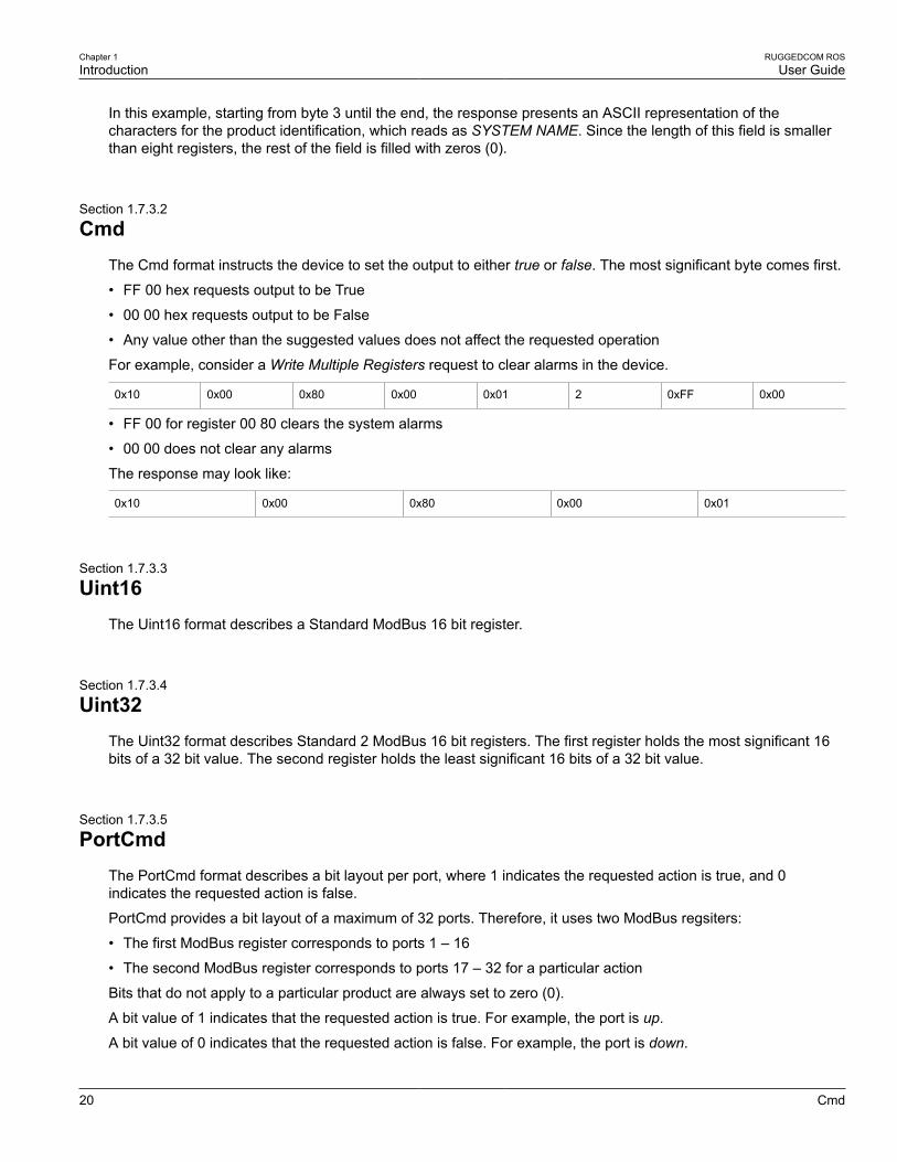
Chapter 1Introduction
RUGGEDCOM ROSUser Guide
20 Cmd
In this example, starting from byte 3 until the end, the response presents an ASCII representation of thecharacters for the product identification, which reads as SYSTEM NAME. Since the length of this field is smallerthan eight registers, the rest of the field is filled with zeros (0).
Section 1.7.3.2
CmdThe Cmd format instructs the device to set the output to either true or false. The most significant byte comes first.
• FF 00 hex requests output to be True
• 00 00 hex requests output to be False
• Any value other than the suggested values does not affect the requested operation
For example, consider a Write Multiple Registers request to clear alarms in the device.
0x10 0x00 0x80 0x00 0x01 2 0xFF 0x00
• FF 00 for register 00 80 clears the system alarms
• 00 00 does not clear any alarms
The response may look like:
0x10 0x00 0x80 0x00 0x01
Section 1.7.3.3
Uint16The Uint16 format describes a Standard ModBus 16 bit register.
Section 1.7.3.4
Uint32The Uint32 format describes Standard 2 ModBus 16 bit registers. The first register holds the most significant 16bits of a 32 bit value. The second register holds the least significant 16 bits of a 32 bit value.
Section 1.7.3.5
PortCmdThe PortCmd format describes a bit layout per port, where 1 indicates the requested action is true, and 0indicates the requested action is false.
PortCmd provides a bit layout of a maximum of 32 ports. Therefore, it uses two ModBus regsiters:
• The first ModBus register corresponds to ports 1 – 16
• The second ModBus register corresponds to ports 17 – 32 for a particular action
Bits that do not apply to a particular product are always set to zero (0).
A bit value of 1 indicates that the requested action is true. For example, the port is up.
A bit value of 0 indicates that the requested action is false. For example, the port is down.

RUGGEDCOM ROSUser Guide
Chapter 1Introduction
Alarm 21
Reading Data Using PortCmdTo understand how to read data using PortCmd, consider a ModBus Request to read multiple registers fromlocatoin 0x03FE.
0x04 0x03 0xFE 0x00 0x02
The response depends on how many parts are available on the device. For example, if the maximum number ofports on a connected RUGGEDCOM device is 20, the response would be similar to the following:
0x04 0x04 0xF2 0x76 0x00 0x05
In this example, bytes 3 and 4 refer to register 1 at location 0x03FE, and represent the status of ports 1 – 16.Bytes 5 and 6 refer to register 2 at location 0x03FF, and represent the status of ports 17 – 32. The device onlyhas 20 ports, so byte 6 contains the status for ports 17 – 20 starting from right to left. The rest of the bites inregister 2 corresponding to the non-existing ports 21 – 31 are zero (0).
Performing Write Actions Using PortCmdTo understand how data is written using PortCmd, consider a Write Multiple Register request to clear Ethernetport statistics:
0x10 0x00 0x83 0x00 0x01 2 0x55 0x76 0x00 0x50
A bit value of 1 clears Ethernet statistics on the corresponding port. A bit value of 0 does not clear the Ethernetstatistics.
0x10 0x00 0x81 0x00 0x02
Section 1.7.3.6
AlarmThe Alarm format is another form of text description. Alarm text corresponds to the alarm description from thetable holding all of the alarms. Similar to the Text format, this format returns an ASCII representation of alarms.
NOTEAlarms are stacked in the device in the sequence of their occurence (i.e. Alarm 1, Alarm 2, Alarm 3,etc.).
The first eight alarms from the stack can be returned, if they exist. A zero (0) value is returned if an alarm doesnot exist.
Section 1.7.3.7
PSStatusCmdThe PSStatusCmd format describes a bit layout for providing the status of available power supplies. Bits 0-4 ofthe lower byte of the register are used for this purpose.
• Bits 0-1: Power Supply 1 Status
• Bits 2-3: Power Supply 2 Status
Other bits in the register do not provide any system status information.
Bit Value Description
01 Power Supply not present (01 = 1)

Chapter 1Introduction
RUGGEDCOM ROSUser Guide
22 TruthValues
Bit Value Description
10 Power Supply is functional (10 = 2)
11 Power Supply is not functional (11 = 3)
The values used for power supply status are derived from the RUGGEDCOM-specific SNMP MIB.
Reading the Power Supply Status from a Device Using PSStatusCmdTo understand how to read the power supply status from a device using PSStatusCmd, consider a ModBusRequest to read multiple registers from location 0x0043.
0x04 0x00 0x43 0x00 0x01
The response may look like:
0x04 0x02 0x00 0x0A
The lower byte of the register displays the power supply's status. In this example, both power supplies in the unitare functional.
Section 1.7.3.8
TruthValuesThe Truthvalues format represents a true or false status in the device:
• 1 indicates the corresponding status for the device to be true
• 2 indicates the corresponding status for the device to be false
Reading the FailSafe Relay Status From a Device Using TruthValueTo understand how to use the TruthValue format to read the FailSafe Relay status from a device, consider aModBus request to read multiple registers from location 0x0044.
0x04 0x00 0x44 0x00 0x01
The response may look like:
0x04 0x02 0x00 0x01
The register's lower byte shows the FailSafe Relay status. In this example, the FailSafe Relay is energized.
Reading the ErrorAlarm Status From a Device Using TruthValueTo understand how to use the TruthValue format to read the ErrorAlarm status from a device, conside a ModBusrequest to read mulitple registers from location 0x0045.
0x04 0x00 0x45 0x00 0x01
The response may look like:
0x04 0x02 0x00 0x01
The register's lower byte shows the ErrorAlarm status. In this example, there is no active ERROR, ALERT orCRITICAL alarm in the device.

RUGGEDCOM ROSUser Guide
Chapter 1Introduction
Certificate and Key Requirements 23
Section 1.8
Certificate and Key RequirementsUsers are able to load custom and unique SSL certificates and SSL/SSH keys in ROS or use the certificates andkeys provided by ROS.
There are three types of certificates and keys:
NOTEDefault and auto-generated SSH keys are not available for Non-Controlled (NC) versions of ROS.
• DefaultEach ROS device is shipped with an SSL certificate and RSA key pair, and a DSA key pair for SSH that areunique to software version. If a valid SSL certificate or SSL/SSH keys are not available on the device, thedefault certificate and keys are used immediately so that SSH and SSL (https) sessions can be served.
• Auto-GeneratedIf a default SSL certificate and SSL/SSH keys are in use, ROS immediately begins to generate a uniquecertificate and SSL/SSH keys for the device in the background. This process takes approximately 5 minutesto complete (depending on how busy the device is at the time) following the startup of the device. If a customcertificate and keys are loaded while auto-generated certificates and keys are being generated, the generatorwill abort and the custom certificate and keys and will be used.
• User-Generated (Recommended)Custom certificates and keys are the most secure option. They give the user complete control over certificateand key management, allow for certificates signed by a public or local certificate authority, controlleddistribution of public SSH keys to network hosts that need them, and more.
NOTEThe RSA key pair must be added to the ssl.crt file after the SSL certificate.
For SSL, ROS requires an X.509 certificate in standard PEM format and an RSA key pair. The certificate maybe self-signed or signed by a separate authoriy. The RSA key must be between 512 and 2048 bits in length. Thecertificate and keys must be combined in a single ssl.crt file and uploaded to the device.
The following is an example of a combined SSL certificate and key:
-----BEGIN CERTIFICATE-----MIIC9jCCAl+gAwIBAgIJAJh6rrehMt3iMA0GCSqGSIb3DQEBBQUAMIGuMQswCQYDVQQGEwJDQTEQMA4GA1UECBMHT250YXJpbzEQMA4GA1UEBxMHQ29uY29yZDESMBAGA1UEChMJUnVnZ2VkY29tMRkwFwYDVQQLExBDdXN0b21lciBTdXBwb3J0MSYwJAYDVQQDEx1XUy1NSUxBTkdPVkFOLlJVR0dFRENPTS5MT0NBTDEkMCIGCSqGSIb3DQEJARYVc3VwcG9ydEBydWdnZWRjb20uY29tMB4XDTEyMTAyMzIxMTA1M1oXDTE3MTAyMjIxMTA1M1owgZwxCzAJBgNVBAYTAlVTMRAwDgYDVQQIEwdPbnRhcmlvMRAwDgYDVQQHEwdDb25jb3JkMRIwEAYDVQQKEwlSdWdnZWRDb20xGTAXBgNVBAsTEEN1c3RvbWVyIFN1cHBvcnQxFDASBgNVBAMTCzE5Mi4xNjguMS4yMSQwIgYJKoZIhvcNAQkBFhVTdXBwb3J0QHJ1Z2dlZGNvbS5jb20wgZ8wDQYJKoZIhvcNAQEBBQADgY0AMIGJAoGBALfE4eh2aY+CE3W5a4Wz1Z1RGRP02COHt153wFFrU8/fFQXNhKlQirlAHbNTRSwcTR8ZFapivwYDivn0ogOGFXknYP90gv2oIaSVY08FqZkJW77g3kzkv/8Zrw3mW/cBsZJ8SyKLIDfy401HkHpDOle5NsQFSrziGUPjAOIvvx4rAgMBAAGjLDAqMAkGA1UdEwQCMAAwHQYDVR0OBBYEFER0utgQOifnrflnDtsqNcnvRB0XMA0GCSqGSIb3DQEBBQUAA4GBAHtBsNZuh8tB3kdqR7Pn+XidCsD70YnI7w0tiy9yiRRhARmVXH8h5Q1rOeHceri3JFFIOxIxQt4KgCUYJLu+c9Esk/nXQQar3zR7IQCt0qOABPkviiY8c3ibVbhJjLpR2vNW4xRAJ+HkNNtBOg1xUlp4vOmJ2syYZR+7XAy/OP/S-----END CERTIFICATE----------BEGIN RSA PRIVATE KEY-----MIICXAIBAAKBgQC3xOHodmmPghN1uWuFs9WdURkT9Ngjh7ded8BRa1PP3xUFzYSp

Chapter 1Introduction
RUGGEDCOM ROSUser Guide
24 Certificate and Key Requirements
UIq5QB2zU0UsHE0fGRWqYr8GA4r59KIDhhV5J2D/dIL9qCGklWNPBamZCVu+4N5M5L//Ga8N5lv3AbGSfEsiiyA38uNNR5B6QzpXuTbEBUq84hlD4wDiL78eKwIDAQABAoGBAI2CXHuHg23wuk9zAusoOhw0MN1/M1jYz0k9aajIvvdZT3Tyd29yCADy8GwAeUmoWXLS/C4CcBqPa9til8ei3rDn/w8dveVHsi9FXjtVSYqN+ilKw+moMAjZy4kN/kpdpHMohwv/909VWR1AZbr+YTxaG/++tKl5bqXnZl4wHF8xAkEA5vwut8USRg2/TndOt1e8ILEQNHvHQdQr2et/xNH4ZEo7mqot6skkCD1xmxA6XG64hR3BfxFSZcewWr4SOFGCtQJBAMurr5FYPJRFGzPM3HwcpAaaMIUtPwNyTtTjywlYcUI7iZVVfbdx4B7qOadPybTg7wqUrGVkPSzzQelz9YCSSV8CQFqpIsEYhbqfTLZEl83YjsuaE801xBivaWLIT0b2TvM2O7zSDOG5fv4I990v+mgrQRtmeXshVmEChtKnBcm7HH0CQE6B2WUfLArDMJ8hAoRczeU1nipXrIh5kWWCgQsTKmUrafdEQvdpT8ja5GpX2Rp98eaUNHfI0cP36JpCdome2eUCQDZN9OrTgPfeDIXzyOiUUwFlzS1idkUGL9nH86iuPnd7WVF3rV9Dse30sVEk63Yky8uKUy7yPUNWldG4U5vRKmY=-----END RSA PRIVATE KEY-----
For SSH, ROS requires a DSA key pair in PEM format. The DSA key must be between 512 and 2048 bits inlength for Controlled versions. The key file is uploaded to the ssh.keys flash file on the device.
The following is an example of a PEM formatted SSH key:
-----BEGIN DSA PRIVATE KEY-----MIIBuwIBAAKBgQD0gcGbXx/rrEMu2913UW4cYo1OlcbnuUz7OZyd2mBLDx/GYbD8X5TnRcMraJ0RuuGK+chqQJW5k3zQmZa/BS6q9U7wYwIAx8JSxxpwfPfl/t09VwKGrtSJIMpLRoDq3qEwEVyR4kDUo4LFQDsljtiyhcz1n6kd6gqsd5Xu1vdh4wIVANXbSBi97GmZ6/9f4UCvIIBtXLEjAoGAAfmhkcCCEnRJitUTiCE+MurxdFUr3mFs/d314cUDaLStQEhYYmx5dbFdQuapl4Y32B7lZQkohi5q1T1iUAa40/nUnJx1hFvblkYT8DLwxcuDAaiu0VqsaPtJ+baL2dYNp96tFisj/475PEEWBGbP6GSe5kKa1Zdgwuie9LyPb+ACgYBv856v5tb9UVG5+tX5Crfv/Nd8FFlSSFKmVWW3yzguhHajg2LQg8UUsm1/zPSwYQ0SbQ9aOAJnpLc2HUkK0lji/0oKVI7y9MMc4B+bGu4W4OnryP7oFpnpYYHt5PJY+zvLw/Wa+u3NOVFHkF1tGyfVBMXeV36nowPo+wrVMolAEgIVALLTnfpWmaV6uh6RxeE1d4XoxSg2-----END DSA PRIVATE KEY-----
For more information about encryption key management, refer to Section 1.2, “Security Recommendations andConsiderations”.

RUGGEDCOM ROSUser Guide
Chapter 2Using ROS
Connecting to ROS 25
Using ROSThis chapter describes how to use the ROS interface. It describes the following tasks:
• Section 2.1, “Connecting to ROS”
• Section 2.2, “Logging In”
• Section 2.3, “Logging Out”
• Section 2.4, “Using the Web Interface”
• Section 2.5, “Using the Console Interface”
• Section 2.6, “Using the Command Line Interface”
• Section 2.7, “Selecting Ports in ROS”
• Section 2.8, “Managing the Flash File System”
• Section 2.9, “Accessing BIST Mode”
Section 2.1
Connecting to ROSThe following describes the various methods for connecting the device:
• Section 2.1.1, “Connecting Directly”
• Section 2.1.2, “Connecting via the Network”
Section 2.1.1
Connecting DirectlyROS can be accessed through a direct serial console or Ethernet connection for management andtroubleshooting purposes. A console connection provides access to the console interface and CLI.
To establish a serial connection to the device, do the following:
1. Connect a workstation (either a terminal or computer running terminal emulation software) to the RS232serial console port on the device. For more information about the RS232 serial console port, refer to theRSG2100 Installation Guide.
NOTEThe baud rate for the device is printed on the chassis exterior near the RS232 serial console port.
2. Configure the workstation as follows:
• Speed (baud): 57600
• Data Bits: 8
• Parity: None

Chapter 2Using ROS
RUGGEDCOM ROSUser Guide
26 Connecting via the Network
• Flow Control: Off
• Terminal ID: VT100
• Stop Bit: 1
3. Connect to the device. Once the connection is established, the login form appears. For more informationabout logging in to the device, refer to Section 2.2, “Logging In”.
Section 2.1.2
Connecting via the NetworkROS can be accessed over the network either through a Web browser, terminal or a workstation running terminalemulation software.
Using a Web BrowserWeb browsers provide a secure connection to the Web interface for ROS using the SSL (Secure Socket Layer)communication method. SSL encrypts traffic exchanged with its clients.
The ROS Web server guarantees that all communications with the client are private. If a client requests accessthrough an insecure HTTP port, the client is automatically rerouted to the secure port. Access to the Web serverthrough SSL will only be granted to clients that provide a valid user name and password.
To establish a connection through a Web browser, do the following:
1. On the workstation being used to access the device, configure an Ethernet port to use an IP address fallingwithin the subnet of the device. The default IP address is 192.168.0.1/24.
For example, to configure the device to connect to one of the available Ethernet ports, assign an IP addressto the Ethernet port on the workstation in the range of 192.168.0.3 to 192.168.0.254.
2. Open a Web browser. For a list of recommended Web browsers, refer to the section called “SystemRequirements”.
IMPORTANT!Upon connecting to the device, some Web browsers may report the Web server's certificatecannot be verified against any known certificates. This is expected behavior, and it is safe toinstruct the browser to accept the certificate. Once the certificate is accepted, all communicationswith the Web server through that browser will be secure.
3. In the address bar, type the IP address for the port that is connected to the network. For example, to accessthe device using its factory default IP address, type https://192.168.0.1 and press Enter. Once theconnection is established, the login screen for the Web interface appears.
For more information about logging in to the device, refer to Section 2.2, “Logging In”. For more informationabout the Web interface, refer to Section 2.4, “Using the Web Interface”.
Using a Terminal or Terminal Emulation SoftwareA terminal or computer running terminal emulation software provides secure access to the console interface forROS through a Telnet, RSH (Remote Shell) or SSH (Secure Shell) service.
NOTEIP services can be restricted to control access to the device. For more information, refer to Section 3.9,“Configuring IP Services”.
To establish a connection through a terminal or terminal emulation software, do the following:

RUGGEDCOM ROSUser Guide
Chapter 2Using ROS
Logging In 27
1. Select the service (i.e. Telnet, RSH or SSH).
2. Enter the IP address for the port that is connected to the network.
3. Connect to the device. Once the connection is established, the login form appears. For more informationabout logging in to the device, refer to Section 2.2, “Logging In”.
Section 2.2
Logging InTo log in to the device, do the following:
1. Connect to the device either directly or through a Web browser. For more information about how to connectto the device, refer to Section 2.1, “Connecting to ROS”.
Once the connection is established, the login form appears.
1
2
Figure 2: SSH Login Screen (Console Interface)
1. User Name Box 2. Password Box
1
3
2
Figure 3: Login Screen (Web Interface)
1. Username Box 2. Password Box 3. Submit Button
NOTEThe following default usernames and passwords are set on the device for each user type:
GuestUsername: guestPassword: guest
OperatorUsername: operatorPassword: operator
AdminUsername: adminPassword: admin

Chapter 2Using ROS
RUGGEDCOM ROSUser Guide
28 Logging Out
CAUTION!To prevent unauthorized access to the device, make sure to change the default guest, operator,and admin passwords before commissioning the device.
For more information about changing passwords, refer to Section 4.3, “Configuring Passwords”.
2. In the User Name field, type the username for an account setup on the device.
3. In the Password field, typ the password for the account.
4. Click Enter or click Submit (Web interface only).
Section 2.3
Logging OutTo log out of the device, navigate to the main screen and do the following:
• To log out of the Console or secure shell interfaces, press CTRL + X.
• To log out of the Web interface, click Logout.
1
Figure 4: Web Interface (Example)
1. Logout
NOTEIf any pending configuration changes have not been committed, ROS will request confirmation beforediscarding the changes and logging out of the device.
Section 2.4
Using the Web InterfaceThe Web interface is a Web-based Graphical User Interface (GUI) for displaying important information andcontrols in a Web browser. The interface is divided into three frames: the banner, the menu and the main frame.

RUGGEDCOM ROSUser Guide
Chapter 2Using ROS
Using the Web Interface 29
2
1
3
Figure 5: Web Interface Layout (Example)
1. Top Frame 2. Side Frame 3. Main Frame
Frame Description
Top The top frame displays the system name for the device.
Side The side frame contains a logout option and a collapsible list of links that open variousscreens in the main frame. For information about logging out of ROS, refer to Section 2.3,“Logging Out”.
Main The main frame displays the parameters and/or data related to the selected feature.
Each screen consists of a title, the current user's access level, parameters and/or data (in form or table format),and controls (e.g. add, delete, refresh, etc.). The title provides access to context-specific Help for the screen thatprovides important information about the available parameters and/or data. Click on the link to open the Helpinformation in a new window.
When an alarm is generated, an alarm notification replaces the current user's access level on each screen untilthe alarm is cleared. The notification indicates how many alarms are currently active. For more information aboutalarms, refer to Section 4.4, “Managing Alarms”.

Chapter 2Using ROS
RUGGEDCOM ROSUser Guide
30 Using the Console Interface
31
2
4
Figure 6: Elements of a Typical Screen (Example)
1. Title 2. Parameters and/or Data 3. Access Level or Alarm Notification 4. Controls
Section 2.5
Using the Console InterfaceThe Console interface is a Graphical User Interface (GUI) organized as a series of menus. It is primarilyaccessible through a serial console connection, but can also be accessed through IP services, such as a Telnet,RSH (Remote Shell), or SSH (Secure Shell) session.
NOTEIP services can be restricted to control access to the device. For more information, refer to Section 3.9,“Configuring IP Services”.
Each screen consists of a system identifier, the name of the current menu, and a command bar. Alarms are alsoindicated on each screen in the upper right corner.

RUGGEDCOM ROSUser Guide
Chapter 2Using ROS
Using the Console Interface 31
5
4
1
2
3
Figure 7: Console Interface (Example)
1. System Identification 2. Menus 3. Command Bar 4. Menu Name 5. Alarms Indicator
NOTEThey system identifier is user configurable. For more information about setting the system name, referto Section 4.1, “Configuring the System Information”.
Navigating the InterfaceUse the following controls to navigate between screens in the Console interface:
Enter Select a menu item and press this Enter to enter the sub-menu or screen beneath.
Esc Press Esc to return to the previous screen.
Configuring ParametersUse the following controls to select and configure parameters in the Console interface:
Up/Down Arrow Keys Use the up and down arrow keys to select parameters.
Enter Select a parameter and press Enter to start editing a parameter. Press Enter again to commit the change.
Esc When editing a parameter, press Esc to abort all changes.
CommandsThe command bar lists the various commands that can be issued in the Console interface. Some commands arespecific to select screens. The standard commands include the following:
Ctrl + A Commits configuration changes made on the current screen.

Chapter 2Using ROS
RUGGEDCOM ROSUser Guide
32 Using the Command Line Interface
NOTEBefore exiting a screen, ROS will automatically prompt the user to save any changes that havenot been committed.
Ctrl + I Inserts a new record.
Ctrl + L Deletes a record.
Ctrl + S Opens the CLI interface.
Ctrl + X Terminates the current session. This command is only available from the main menu.
Ctrl + Z Displays important information about the current screen or selected parameter.
Section 2.6
Using the Command Line InterfaceThe Command Line Interface (CLI) offers a series of powerful commands for updating ROS, generatingcertificates/keys, tracing events, troubleshooting and much more. It is accessed via the Console interface bypressing Ctrl-S.
The following sections describe how to use the Command Line Interface (CLI):
• Section 2.6.1, “Available CLI Commands”
• Section 2.6.2, “Tracing Events”
• Section 2.6.3, “Executing Commands Remotely via RSH”
• Section 2.6.4, “Using SQL Commands”
Section 2.6.1
Available CLI CommandsThe following commands are available at the command line:
Command Description
alarms all Displays a list of available alarms.
Optional and/or required parameters include:
• all displays all available alarms
arp Displays the IP to MAC address resolution table.
clearalarms Clears all alarms.
clearethstats [all | port] Clears Ethernet statistics for one or more ports.
Optional and/or required parameters include:
• all clears statistics for all ports• port is a comma separated list of port numbers (e.g. 1,3-5,7)
clearlogs Clears the system and crash logs.
clrcblstats [all | port] Clears cable diagnostics statistics for one or more ports.
Optional and/or required parameters include:
• all clears statistics for all ports

RUGGEDCOM ROSUser Guide
Chapter 2Using ROS
Available CLI Commands 33
Command Description
• port is a comma separated list of port numbers (e.g. 1,3-5,7)
clrstpstats Clears all spanning tree statistics.
cls Clears the screen.
dir Prints the directory listing.
exit Terminates the session.
factory Enables factory mode, which includes several factory-level commands used for testing andtroubleshooting. Only available to admin users.
CAUTION!Misuse of the factory commands may corrupt the operational state of deviceand/or may permanently damage the ability to recover the device withoutmanufacturer intervention.
flashfiles {info filename |defrag}
A set of diagnostic commands to display information about the Flash filesystem and todefragment Flash memory.
Optional and/or required parameters include:
• info filename displays information about the specified file in the Flash file system• defrag defragments files in the Flash file system
For more information about the flashfiles command, refer to Section 2.8, “Managing theFlash File System”.
flashleds timeout Flashes the LED indicators on the device for a specified number of seconds.
Optional and/or required parameters include:
• timeout is the number of seconds to flash the LED indicators. To stop the LEDs fromflashing, set the timeout period to 0 (zero).
fpgacmd Provides access to the FPGA management tool for troubleshooting time synchronization.
help command Displays a brief description of the specified command. If no command is specified, itdisplays a list of all available commands, including a description for each.
Optional and/or required parameters include:
• command is the command
ipconfig Displays the current IP address, subnet mask and default gateway. This command providesthe only way of determining these values when DHCP is used.
loaddflts Loads the factory default configuration.
login Logs in to the shell.
logout Logs out of the shell.
ping address {count | timeout} Sends an ICMP echo request to a remotely connected device. For each reply received, theround trip time is displayed. Use this command to verify connectivity to the next connecteddevice. It is a useful tool for testing commissioned links. This command also includesthe ability to send a specific number of pings with a specified time for which to wait for aresponse.
Optional and/or required parameters include:
• address is the target IP address.• count is the number of echo requests to send. The default is 4.• timeout is the time in milliseconds to wait for each reply. The range is 2 to 5000
seconds. The default is 300 milliseconds.
NOTEThe device to be pinged must support ICMP echo. Upon commencing the ping,an ARP request for the MAC address of the device is issued. If the device to be

Chapter 2Using ROS
RUGGEDCOM ROSUser Guide
34 Available CLI Commands
Command Description
pinged is not on the same network as the device pinging the other device, thedefault gateway must be programmed.
purgemac Purges the MAC Addrtess table.
reset Perform a hard reset of the switch.
resetport {all | ports} Resets one or more Ethernet ports, which may be useful for forcing re-negotiation of speedand duplex, or in situations where the link partner has latched into an inappropriate state.
Optional and/or required parameters include:
• all resets all ports• ports is a comma separated list of port numbers (e.g. 1,3-5,7)
rmon Displays the names of all RMON alarm eligible objects.
route Displays the gateway configuration.
sfp port {base | alarms | diag |calibr | thr | all | no parameterspecified}
Displays SFP (Small Form Factor Pluggable) device information and diagnostics. If optionalor required parameters are not used, this command displays the base and extendedinformation.
Optional and/or required parameters include:
• port is the port number for which the data are required• base displays the base information• alarms displays alarms and warning flags• diag displays measured data• calibr displays calibration data for external calibration• thr displays thresholds data• all displays all diagnostic data
sql {default | delete | help |info | insert | save | select |update}
Provides an SQL-like interface for manipulating all system configuration and statusparameters. All commands, clauses, table, and column names are case insensitive.
Optional and/or required parameters include:
• default sets all records in a table(s) to factory defaults• delete allows for records to be deleted from a table• help provides a brief description for any SQL command or clause• info displays a variety of information about the tables in the database• insert enables new records to be inserted into a table• save saves the database to non-volatile memory storage• select queries the dtabase and displays selected records• update enable existing records in a table to be updated
For more information about the sql command, refer to Section 2.6.4, “Using SQLCommands”.
sshkeygen size Generates new SSH keys in ssh.keys.
Optional and/or required parameters include:
• size is the number of bits in length between 512 and 2048. The default is 1024 bits.
sslkeygen size Generates a new SSL certificate in ssl.crt.
Optional and/or required parameters include:
• size is the number of bits in length between 512 and 2048. The default is 1024 bits.
telnet dest Opens a telnet session. Press Ctrl-C to close the session.
Optional and/or required parameters include:
• dest is the server's IP address
tftp {dest | cmd | fsource |fdest}
Opens a TFTP session. Press Ctrl-C to close the session.

RUGGEDCOM ROSUser Guide
Chapter 2Using ROS
Tracing Events 35
Command Description
Optional and/or required parameters include:
• dest is the remote TFTP server's IP address• cmd is either put (upload) or get (download)• fsource is the source filename• fdest is the destination filename
trace Starts event tracing. Run trace ? for more help.
type filename Displays the contents of a text file.
Optional and/or required parameters include:
• filename is the name of the file to be read
version Prints the software version.
xmodem {send | receive} filename Opens an XModem session.
Optional and/or required parameters include:
• send sends the file to the client.• receive receives the file from the client.• filename is the name of the file to be read.
Section 2.6.2
Tracing EventsThe CLI trace command provides a means to trace the operation of various protocols supported by the device.Trace provides detailed information, including STP packet decodes, IGMP activity and MAC address displays.
NOTETracing has been designed to provide detailed information to expert users. Note that all tracing isdisabled upon device startup.
To trace an event, do the following:
1. Log in to the device as an admin user and access the CLI shell. For more information about accessing theCLI shell, refer to Section 2.6, “Using the Command Line Interface”.
2. Determine the protocols and associated options available by typing:
trace ?
If an option such as allon or alloff is required, determine which options are available for the desiredprotocol by typing:
trace protocol ?
NOTEIf required, expand the trace scope by stringing protocols and their associated options togetherusing a vertical bar (|).
3. Select the type of trace to run by typing:
trace protocol option
Where:
• protocol is the protocol to trace
Chapter 2Using ROS
RUGGEDCOM ROSUser Guide
36 Executing Commands Remotely via RSH
• option is the option to use during the trace
Example:
>trace transport allon TRANSPORT: Logging is enabled
4. Start the trace by typing:
trace
Section 2.6.3
Executing Commands Remotely via RSHThe Remote Shell (RSH) facility can be used from a workstation to cause the product to act upon commands as ifthey were entered at the CLI prompt. The syntax of the RSH command is usually of the form:
rsh ipaddr –l auth_token command_string
Where:
• ipaddr is the address or resolved name of the device.
• auth_token is the user name (i.e. guest, operator or admin) and corresponding password separated by acomma. For example, admin,secret.
• command_string is the ROS CLI command to execute.
NOTEThe access level (corresponding to the user name) selected must support the given command.
NOTEAny output from the command will be returned to the workstation submitting the command. Commandsthat start interactive dialogs (such as trace) cannot be used.
Section 2.6.4
Using SQL CommandsROS provides an SQL-like command facility that allows expert users to perform several operations not possibleunder the traditional Web or CLI interface. For instance:
• Restoring the contents of a specific table, but not the whole configuration, to their factory defaults.
• Search tables in the database for specific configurations.
• Make changes to tables predicated upon existing configurations.
When combined with RSH, SQL commands provide a means to query and configure large numbers of devicesfrom a central location.
NOTEFor a list of parameters available under the sql command, refer to Section 2.6.1, “Available CLICommands”.
RUGGEDCOM ROSUser Guide
Chapter 2Using ROS
Finding the Correct Table 37
The following sections describe in more detail how to use SQL commands:
• Section 2.6.4.1, “Finding the Correct Table”
• Section 2.6.4.2, “Retrieving Information”
• Section 2.6.4.3, “Changing Values in a Table”
• Section 2.6.4.4, “Resetting a Table”
• Section 2.6.4.5, “Using RSH and SQL”
Section 2.6.4.1
Finding the Correct TableMany SQL commands operate upon specific tables in the database, and require the table name to be specified.Navigating the menu system in the console interface to the desired menu and pressing Ctrl-Z displays the nameof the table. The menu name and the corresponding database table name will be cited.
Another way to find a table name is to type the following in the CLI:
sql info tables
This command also displays menu names and their corresponding database table names depending upon thefeatures supported by the device. For example:
Table Description-------------------------------------------------------------------------------alarms AlarmscpuDiags CPU DiagnosticsethPortCfg Port ParametersethPortStats Ethernet StatisticsethPortStatus Port StatusipCfg IP Services
Section 2.6.4.2
Retrieving InformationThe following describes various methods for retrieving information about tables and parameters.
Retrieving Information from a TableUse the following command to display a summary of the parameters within a table, as well as their values:
sql select from table
Where:
• table is the name of the table
Example:
>sql select from ipAddrtable
IP Address Subnet IfIndex IfStats IfTime IfName 172.30.146.88 255.255.224.0 1001 17007888 2994 vlan1
1 records selected
Chapter 2Using ROS
RUGGEDCOM ROSUser Guide
38 Retrieving Information
Retrieving Information About a Parameter from a TableUse the following command to retrieve information about a specific parameter from a table:
NOTEThe parameter name must be the same as it is displayed in the menu system, unless the namecontains spaces (e.g. ip address). Spaces must be replaced with underscores (e.g. ip_address) or theparameter name must be wrapped in double quotes (e.g. "ip address").
sql select parameter from table
Where:
• parameter is the name of the parameter
• table is the name of the table
Example:
>sql select "ip address" from ipSwitchIfCfg
IP Address192.168.0.1
1 records selected
Retrieving Information from a Table Using the Where ClauseUse the following command to display specific parameters from a table that have a specific value:
sql select from table where parameter = value
Where:
• table is the name of the table
• parameter is the name of the parameter
• value is the value of the parameter
Example:
>sql select from ethportcfg where media = 1000T
Port Name ifName Media State AutoN Speed Dupx FlowCtrl LFI Alarm1 Port 1 1 1000T Enabled On Auto Auto Off Off On2 Port 2 2 1000T Enabled On Auto Auto Off Off On3 Port 3 3 1000T Enabled On Auto Auto Off Off On4 Port 4 4 1000T Enabled On Auto Auto Off Off On
4 records selected
Further refine the results by using and or or operators:
sql select from table where parameter = value [{and | or} | parameter | = | value...]
Where:
• table is the name of the table
• parameter is the name of the parameter
• value is the value of the parameter
Example:
>sql select from ethportcfg where media = 1000T and State = enabled

RUGGEDCOM ROSUser Guide
Chapter 2Using ROS
Changing Values in a Table 39
Port Name ifName Media State AutoN Speed Dupx FlowCtrl LFI Alarm1 Port 1 1 1000T Enabled On Auto Auto Off Off on2 Port 2 2 1000T Enabled On Auto Auto Off Off On3 Port 3 3 1000T Enabled On Auto Auto Off Off On4 Port 4 4 1000T Enabled On Auto Auto Off Off On
4 records selected
Section 2.6.4.3
Changing Values in a TableUse the following command to change the value of parameters in a table:
sql update table set parameter = value
Where:
• table is the name of the table
• parameter is the name of the parameter
• value is the value of the parameter
Example:
>sql update iplcfg set IP_Address_Type = static1 records updated
Conditions can also be included in the command to apply changes only to parameters that meet specific criteria.In the following example, flow control is enabled on ports that are operating in 100 Mbps full-duplex mode withflow control disabled:
>sql update ethportcfg set FlowCtrl = Off where ( Media = 100TX and FlowCtrl = On )2 records updated
Section 2.6.4.4
Resetting a TableUse the following command to reset a table back to its factory defaults:
sql default into table
Where:
• table is the name of the table
Section 2.6.4.5
Using RSH and SQLThe combination of remote shell scripting and SQL commands offers a means to interrogate and maintain alarge number of devices. Consistency of configuration across sites may be verified by this method. The followingpresents a simple example where the devices to interrogate are drawn from the file Devices:
Need a new example not related to VLANs
C:> type Devices

Chapter 2Using ROS
RUGGEDCOM ROSUser Guide
40 Selecting Ports in ROS
10.0.1.110.0.1.2
C:\> for /F %i in (devices) do rsh %i -l admin,admin sql select from ipAddrtable
C:\>rsh 10.0.1.1 -l admin,admin sql select from ipAddrtable
IP Address Subnet IfIndex IfStats IfTime IfName192.168.0.31 255.255.255.0 1001 274409096 2218 vlan1
1 records selected
C:\>rsh 10.0.1.2 -l admin,admin sql select from ipAddrtable0 records selectedC:\
Section 2.7
Selecting Ports in ROSMany features in ROS can be configured for one or more ports on the device. The following describes how tospecify a single port, a range of ports, or all ports.
Select a single port by specifying the port number:
2
Select a range of ports using a dash (-) between the first port and the last port in the list:
1-4
Select multiple ports by defining a comma-separated list:
1,4,6,9
Use the All option to select all ports in the device, or, if available, use the None option to select none of theports.
Section 2.8
Managing the Flash File SystemThe following sections describe how to manage the flash file system:
• Section 2.8.1, “Viewing a List of Flash Files”
• Section 2.8.2, “Viewing Flash File Details”
• Section 2.8.3, “Defragmenting the Flash File System”
Section 2.8.1
Viewing a List of Flash FilesTo view a list of files currently stored in Flash memory, do the following:

RUGGEDCOM ROSUser Guide
Chapter 2Using ROS
Viewing Flash File Details 41
1. Log in to the device as an admin user and access the CLI shell. For more information about accessing theCLI shell, refer to Section 2.6, “Using the Command Line Interface”.
2. Type flashfiles. A list of files currently in Flash memory is displayed, along with their locations and theamount of memory they consume. For example:
>flashfiles-----------------------------------------------------------------Filename Base Size Sectors Used-----------------------------------------------------------------boot.bin 00000000 110000 0-16 1095790main.bin 00110000 140000 17-36 1258403fpga.xsvf 00250000 010000 37-37 55882syslog.txt 00260000 140000 38-57 19222ssh.keys 003A0000 010000 58-58 915ssl.crt 003B0000 010000 59-59 1970banner.txt 003C0000 010000 60-60 256crashlog.txt 003D0000 010000 61-61 256config.bak 003E0000 010000 62-62 15529config.csv 003F0000 008000 63-63 15529factory.txt 003FC000 004000 66-66 407-----------------------------------------------------------------
Section 2.8.2
Viewing Flash File DetailsTo view the details of a file currently stored in Flash memory, do the following:
1. Log in to the device as an admin user and access the CLI shell. For more information about accessing theCLI shell, refer to Section 2.6, “Using the Command Line Interface”.
2. Display information about a file by typing:
flashfiles info filename
Where:
• filename is the name of the file stored in Flash memory
Details, similar to the following, are displayed.
Updated for RP110
>flashfiles info main.bin
Flash file information for main.bin:Header version : 4Platform : ROS-CF52
File name : main.binFirmware version : v4.1.0Build date : Sep 27 2014 15:50File length : 2624659Board IDs : 3dHeader CRC : 73b4Header CRC Calc : 73b4Body CRC : b441Body CRC Calc : b441

Chapter 2Using ROS
RUGGEDCOM ROSUser Guide
42 Defragmenting the Flash File System
Section 2.8.3
Defragmenting the Flash File SystemThe flash memory is defragmented automatically whenever there is not enough memory available for a binaryupgrade. However, fragmentation can occur whenever a new file is uploaded to the unit. Fragmentation causessectors of available memory to become separated by ones allocated to files. In some cases, the total availablememory might be sufficient for a binary upgrade, but that memory may not be available in one contiguous region.
To defragment the flash memory, do the following:
1. Log in to the device as an admin user and access the CLI shell. For more information about accessing theCLI shell, refer to Section 2.6, “Using the Command Line Interface”.
2. Defragment the flash memory by typing:
flashfiles defrag
Section 2.9
Accessing BIST ModeBIST (Built-In-Self-Test) mode is used by service technicians to test and configure internal functions of the device.It should only be accessed for troubleshooting purposes.
CAUTION!Mechanical hazard – risk of damage to the device. Excessive use of BIST functions may causeincrease wear on the device, which may void the warranty. Avoid using BIST functions unlessinstructed by a Siemens Customer Support representative.
To access BIST mode, do the following:
IMPORTANT!Do not connect the device to the network when it is in BIST mode. The device will generate excessmulticast traffic in this mode.
1. Disconnect the device from the network.
2. Connect to ROS through the RS232 console connection and a terminal application. For more information,refer to Section 2.1.1, “Connecting Directly”.
3. Reset the device. For more information, refer to Section 3.12, “Resetting the Device”.
4. During the boot up sequence, press Ctrl-C when prompted. The command prompt for BIST appears.
>
5. Type help to view a list of all available options under BIST.

RUGGEDCOM ROSUser Guide
Chapter 3Device Management
Viewing Product Information 43
Device ManagementThis chapter describes how to configure and manage the device and its components, such as module interfaces,logs and files. It describes the following tasks:
NOTEFor information about how to configure the device to work with a network, refer to Chapter 5, Setup andConfiguration.
• Section 3.1, “Viewing Product Information”
• Section 3.2, “Viewing CPU Diagnostics”
• Section 3.3, “Restoring Factory Defaults”
• Section 3.4, “Uploading/Downloading Files”
• Section 3.5, “Managing Logs”
• Section 3.6, “Managing Ethernet Ports”
• Section 3.7, “Managing IP Interfaces”
• Section 3.8, “Managing IP Gateways”
• Section 3.9, “Configuring IP Services”
• Section 3.10, “Managing Remote Monitoring”
• Section 3.11, “Upgrading/Downgrading Firmware”
• Section 3.12, “Resetting the Device”
• Section 3.13, “Decommissioning the Device”
Section 3.1
Viewing Product InformationDuring troubleshooting or when ordering new devices, Siemens personnel may request specific information aboutthe device, such as the model, order code or serial number.
To view information about the device, navigate to Diagnostics » View Product Information. The ProductInformation form appears.

Chapter 3Device Management
RUGGEDCOM ROSUser Guide
44 Viewing Product Information
9
5
4
3
2
1
6
7
8
Figure 8: Product Information Form (Example)1. MAC Address Box 2. Order Code Box 3. Classification Box 4. Serial Number Box 5. Boot Version Box 6. Main Version Box 7. Required Boot Box 8. Hardware ID Box 9. Reload Button
This screen displays the following information:
Parameter Description
MAC Address Synopsis: ##-##-##-##-##-## where ## ranges 0 to FF
Shows the unique MAC address of the device.
Order Code Synopsis: Any 57 characters
Shows the order code of the device.
Classification Synopsis: Any 15 characters
Provides system classification.
The value Controlled indicates the main firmware is a Controlled release. The value Non-Controlled indicates the main firmware is a Non-Controlled release. The Controlled mainfirmware can run on Controlled units, but it can not run on Non-Controlled units. The Non-Controlled main firmware can run on both Controlled and Non-Controlled units.
Serial Number Synopsis: Any 31 characters
Shows the serial number of the device.
Boot Version Synopsis: Any 47 characters
Shows the version and the build date of the boot loader software.
Main Version Synopsis: Any 47 characters
Shows the version and build date of the main operating system software.
Required Boot Synopsis: Any 15 characters
Shows the minimum boot software loader version required by running main.
Hardware ID Synopsis: { RSMCPU (40-00-0008 Rev B1), RSMCPU2 (40-00-0026 Rev A1), RS400(40-00-0010 Rev B2), RMC30, RS900 (40-00-0025 Rev B1), RS900 (40-00-0032 RevB1), RS1600M, RS400 (40-00-0010 Rev C1), RSG2100, RS900G, RSG2200, RS969,RS900 (v2, 40-00-0066), RS900 (v2, 40-00-0067), , RS416 (40-00-0078), RMC30 (v2),RS930 (40-00-0089), RS969 (v2, 40-00-0090), RS910 (40-00-0091-001 Rev A), RS920L(40-00-0102-001 Rev A), RS940G (40-00-0097-000 Rev A), RSi80X series CPU board,RSG2300, RS416v2, ... }

RUGGEDCOM ROSUser Guide
Chapter 3Device Management
Viewing CPU Diagnostics 45
Parameter Description
Shows the type, part number, and revision level of the hardware.
Section 3.2
Viewing CPU DiagnosticsTo view CPU diagnostic information useful for troubleshooting hardware and software performance, navigate toDiagnostics » View CPU Diagnostics. The CPU Diagnostics form appears.
2
11
1
3
4
5
6
7
8
9
Figure 9: CPU Diagnostics Form1. Running Time Box 2. Total Powered Time Box 3. CPU Usage Box 4. RAM Total Box 5. RAM Free Box 6. RAM Low WatermarkBox 7. Temperature Box 8. Free Rx Bufs Box 9. Free Tx Bufs Box 10. Reload Button
This screen displays the following information:
Parameter Description
Running Time Synopsis: DDDD days, HH:MM:SS
The amount of time since the device was last powered on.
Total Powered time Synopsis: DDDD days, HH:MM:SS
The cumulative powered up time of the device.
CPU Usage Synopsis: 0.0 to 100.0%
The percentage of available CPU cycles used for device operation as measured over thelast second.
RAM Total Synopsis: 0 to 4294967295
The total size of RAM in the system.
RAM Free Synopsis: 0 to 4294967295
The total size of RAM still available.
RAM Low Watermark Synopsis: 0 to 4294967295

Chapter 3Device Management
RUGGEDCOM ROSUser Guide
46 Restoring Factory Defaults
Parameter Description
The size of RAM that have never been used during the system runtime.
Temperature Synopsis: -32768 to 32767 C
The temperature on CPU board.
Free Rx Bufs Synopsis: 0 to 4294967295
Free Rx Buffers.
Free Tx Bufs Synopsis: 0 to 4294967295
Free Tx Buffers.
Section 3.3
Restoring Factory DefaultsThe device can be completely or partially restored to its original factory default settings. Excluding groups ofparameters from the factory reset, such as those that affect basic connectivity and SNMP management, is usefulwhen communication with the device is still required during the reset.
The following categories are not affected by a selective configuration reset:
• IP Interfaces
• IP Gateways
• SNMP Users
• SNMP Security to Group Maps
• SNMP Access
• RUGGEDCOM Discovery Protocol™ (RCDP)
In addition, the following categories are not affected by a full or selective configuration reset:
• Time Zone
• DST Offset
• DST Rule
To restore factory defaults, do the following:
1. Navigate to Diagnostics » Load Factory Defaults. The Load Factory Defaults form appears.
32
1
Figure 10: Load Factory Defaults Form
1. Defaults Choice List 2. Apply Button 3. Reload
2. Configure the following parameter(s) as required:
RUGGEDCOM ROSUser Guide
Chapter 3Device Management
Uploading/Downloading Files 47
NOTEIf the VLAN ID for the Management IP interface is not 1, setting Defaults Choice to Selectedwill automatically set it to 1.
Parameter Description
Defaults Choice Synopsis: { None, Selected, All }
Setting some records like IP Interfaces management interface, default gateway, SNMPsettings to default value would cause switch not to be accessible with managementapplications. This parameter allows user to choose to load defaults to Selected tables,which would preserve configuration for tables that are critical for switch managementapplications, or to force All tables to default settings.
3. Click Apply.
Section 3.4
Uploading/Downloading FilesFiles can be transferred between the device and a host computer using any of the following methods:
• Xmodem using the CLI shell over a Telnet or RS232 console session
• TFTP client using the CLI shell in a console session and a remote TFTP server
• TFTP server from a remote TFTP client
• SFTP (secure FTP over SSH) from a remote SFTP client
NOTEThe contents of the internal file system are fixed. New files and directories cannot be created, andexisting files cannot be deleted. Only the files that can be uploaded to the device can be overwritten.
Files that may need to be uploaded or downloaded include:
• main.bin – the main ROS application firmware image
• boot.bin – the boot loader firmware image
• fpga.xsvf – the FPGA firmware binary image
• config.csv – the complete configuration database, in the form of a comma-delimited ASCII text file
• banner.txt – contains text that appears on the login screen
The following sections describe how to upload and download files:
• Section 3.4.1, “Uploading/Downloading Files Using XMODEM”
• Section 3.4.2, “Uploading/Downloading Files Using a TFTP Client”
• Section 3.4.3, “Uploading/Downloading Files Using a TFTP Server”
• Section 3.4.4, “Uploading/Downloading Files Using an SFTP Server”
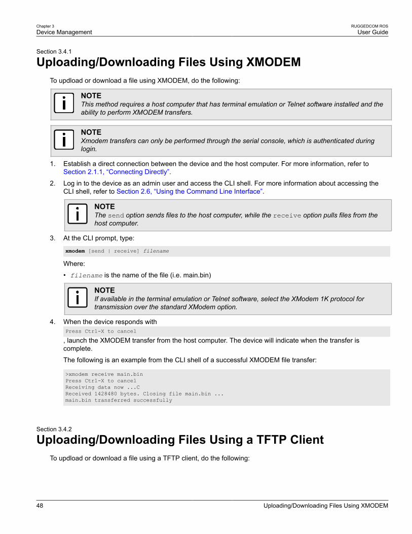
Chapter 3Device Management
RUGGEDCOM ROSUser Guide
48 Uploading/Downloading Files Using XMODEM
Section 3.4.1
Uploading/Downloading Files Using XMODEMTo updload or download a file using XMODEM, do the following:
NOTEThis method requires a host computer that has terminal emulation or Telnet software installed and theability to perform XMODEM transfers.
NOTEXmodem transfers can only be performed through the serial console, which is authenticated duringlogin.
1. Establish a direct connection between the device and the host computer. For more information, refer toSection 2.1.1, “Connecting Directly”.
2. Log in to the device as an admin user and access the CLI shell. For more information about accessing theCLI shell, refer to Section 2.6, “Using the Command Line Interface”.
NOTEThe send option sends files to the host computer, while the receive option pulls files from thehost computer.
3. At the CLI prompt, type:
xmodem [send | receive] filename
Where:
• filename is the name of the file (i.e. main.bin)
NOTEIf available in the terminal emulation or Telnet software, select the XModem 1K protocol fortransmission over the standard XModem option.
4. When the device responds withPress Ctrl-X to cancel
, launch the XMODEM transfer from the host computer. The device will indicate when the transfer iscomplete.
The following is an example from the CLI shell of a successful XMODEM file transfer:
>xmodem receive main.binPress Ctrl-X to cancelReceiving data now ...CReceived 1428480 bytes. Closing file main.bin ...main.bin transferred successfully
Section 3.4.2
Uploading/Downloading Files Using a TFTP ClientTo updload or download a file using a TFTP client, do the following:

RUGGEDCOM ROSUser Guide
Chapter 3Device Management
Uploading/Downloading Files Using a TFTP Server 49
IMPORTANT!TFTP does not define an authentication scheme. Any use of the TFTP client or server is consideredhighly insecure.
NOTEThis method requires a TFTP server that is accessible over the network.
1. Identify the IP address of the computer running the TFTP server.
2. Establish a direct connection between the device and a host computer. For more information, refer toSection 2.1.1, “Connecting Directly”.
3. Log in to the device as an admin user and access the CLI shell. For more information about accessing theCLI shell, refer to Section 2.6, “Using the Command Line Interface”.
4. At the CLI prompt, type:
tftp address [get | put] source-filename destination-filename
Where:
• get copies files from the host computer to the device
• put copies files from the device to the host computer
• address is the IP address of the computer running the TFTP server
• source-filename is the name of the file to be transferred
• destination-filename is the name of the file (on the device or the TFTP server) that will be replacedduring the transfer
The following is an example of a successful TFTP client file transfer:
>tftp 10.0.0.1 get ROS-CF52_Main_v3.7.0.bin main.binTFTP CMD: main.bin transfer ok. Please wait, closing file ...TFTP CMD: main.bin loading succesful.
Section 3.4.3
Uploading/Downloading Files Using a TFTP ServerTo updload or download a file using a TFTP server, do the following:
IMPORTANT!TFTP does not define an authentication scheme. Any use of the TFTP client or server is consideredhighly insecure.
NOTEThis method requires a host computer that has TFTP server software installed.
IMPORTANT!Interaction with TFTP servers is strictly controlled within the device to prevent unauthorized access.Make sure the device is configured to accept the TFTP connection. For more information, refer toSection 3.9, “Configuring IP Services”.

Chapter 3Device Management
RUGGEDCOM ROSUser Guide
50 Uploading/Downloading Files Using an SFTP Server
1. Establish a direct connection between the device and the host computer. For more information, refer toSection 2.1.1, “Connecting Directly”.
2. Initialize the TFTP server on the host computer and launch the TFTP transfer. The server will indicate whenthe transfer is complete.
The following is an example of a successful TFTP server exchange:
C:\>tftp -i 10.1.0.1 put C:\files\ROD-CF52_Main_v3.7.0.bin main.binTransfer successful: 1428480 bytes in 4 seconds, 375617 bytes/s
Section 3.4.4
Uploading/Downloading Files Using an SFTP ServerSFTP (Secure File Transfer Protocol) is a file transfer mechanism that uses SSH to encrypt every aspect of filetransfer between a networked client and server.
NOTEThe device does not have an SFTP client and, therefore, can only receive SFTP files from an externalsource. SFTP requires authentication for the file transfer.
To updload or download a file using an SFTP server, do the following:
NOTEThis method requires a host computer that has SFTP client software installed.
1. Establish an SFTP connection between the device and the host computer.
2. Launch the SFTP transfer. The client will indicate when the transfer is complete.
The following is an example of a successful SFTP server exchange:
user@host$ sftp admin@ros_ipConnecting to ros_ip...admin@ros_ip's password:sftp> put ROS-CF52_Main_v3-7-0.bin main.binUploading ROS-CF52_Main_v3-7-0.bin to /main.binROS-CF52_Main_v3-7-0.bin 100% 2139KB 48.6KB/s 00:44sftp>
Section 3.5
Managing LogsThe crash (crashlog.txt) and system (syslog.txt) log files contain historical information about events thathave occurred during the operation of the device.
The crash log contains debugging information related to problems that might have resulted in unplanned restartsof the device or which may effect the operation of the device. A file size of 0 bytes indicates that no unexpectedevents have occurred.
The system log contains a record of significant events including startups, configuration changes, firmwareupgrades and database re-initializations due to feature additions. The system log will accumulate information untilit is full, holding approximately 2 MB of data.
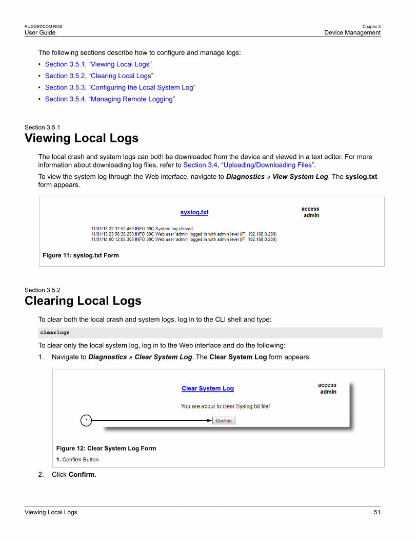
RUGGEDCOM ROSUser Guide
Chapter 3Device Management
Viewing Local Logs 51
The following sections describe how to configure and manage logs:
• Section 3.5.1, “Viewing Local Logs”
• Section 3.5.2, “Clearing Local Logs”
• Section 3.5.3, “Configuring the Local System Log”
• Section 3.5.4, “Managing Remote Logging”
Section 3.5.1
Viewing Local LogsThe local crash and system logs can both be downloaded from the device and viewed in a text editor. For moreinformation about downloading log files, refer to Section 3.4, “Uploading/Downloading Files”.
To view the system log through the Web interface, navigate to Diagnostics » View System Log. The syslog.txtform appears.
Figure 11: syslog.txt Form
Section 3.5.2
Clearing Local LogsTo clear both the local crash and system logs, log in to the CLI shell and type:
clearlogs
To clear only the local system log, log in to the Web interface and do the following:
1. Navigate to Diagnostics » Clear System Log. The Clear System Log form appears.
1
Figure 12: Clear System Log Form
1. Confirm Button
2. Click Confirm.

Chapter 3Device Management
RUGGEDCOM ROSUser Guide
52 Configuring the Local System Log
Section 3.5.3
Configuring the Local System LogTo configure the severity level for the local system log, do the following:
NOTEFor maximum reliability, use remote logging. For more information, refer to Section 3.5.4, “ManagingRemote Logging”.
1. Navigate to Administration » Configure Syslog » Configure Local Syslog. The Local Syslog formappears.
32
1
Figure 13: Local Syslog Form
1. Local Syslog Level 2. Apply Button 3. Reload Button
2. Configure the following parameter(s) as required:
Parameter Description
Local Syslog Level Synopsis: { EMERGENCY, ALERT, CRITICAL, ERROR, WARNING, NOTICE,INFORMATIONAL, DEBUGGING }Default: INFORMATIONAL
The severity of the message that has been generated. Note that the severity levelselected is considered the minimum severity level for the system. For example, ifERROR is selected, the system sends any syslog messages generated by Error,Critical, Alert and Emergency.
3. Click Apply.
Section 3.5.4
Managing Remote LoggingIn addition to the local system log maintained on the device, a remote system log can be configured as well tocollect important event messages. The syslog client resides on the device and supports up to 5 collectors (orsyslog servers).
The remote syslog protocol, defined in RFC 3164, is a UDP/IP-based transport that enables the device to sendevent notification messages across IP networks to event message collectors, also known as syslog servers. Theprotocol is designed to simply transport these event messages from the generating device to the collector(s).
The following sections describe how to configure a remote syslog client and server:
• Section 3.5.4.1, “Configuring the Remote Syslog Client”
• Section 3.5.4.2, “Viewing a List of Remote Syslog Servers”
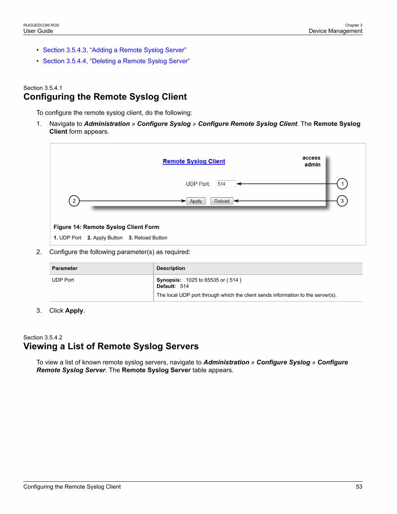
RUGGEDCOM ROSUser Guide
Chapter 3Device Management
Configuring the Remote Syslog Client 53
• Section 3.5.4.3, “Adding a Remote Syslog Server”
• Section 3.5.4.4, “Deleting a Remote Syslog Server”
Section 3.5.4.1
Configuring the Remote Syslog ClientTo configure the remote syslog client, do the following:
1. Navigate to Administration » Configure Syslog » Configure Remote Syslog Client. The Remote SyslogClient form appears.
32
1
Figure 14: Remote Syslog Client Form
1. UDP Port 2. Apply Button 3. Reload Button
2. Configure the following parameter(s) as required:
Parameter Description
UDP Port Synopsis: 1025 to 65535 or { 514 }Default: 514
The local UDP port through which the client sends information to the server(s).
3. Click Apply.
Section 3.5.4.2
Viewing a List of Remote Syslog ServersTo view a list of known remote syslog servers, navigate to Administration » Configure Syslog » ConfigureRemote Syslog Server. The Remote Syslog Server table appears.

Chapter 3Device Management
RUGGEDCOM ROSUser Guide
54 Adding a Remote Syslog Server
Figure 15: Remote Syslog Server Table
If remote syslog servers have not been configured, add the servers as needed. For more information, refer toSection 3.5.4.3, “Adding a Remote Syslog Server”.
Section 3.5.4.3
Adding a Remote Syslog ServerROS supports up to 5 remote syslog servers (or collectors). Similar to the local system log, a remote system logserver can be configured to log information at a specific severity level. Only messages of a severity level equal toor greater than the specified severity level are written to the log.
To add a remote syslog server to the list of known servers, do the following:
1. Navigate to Administration » Configure Syslog » Configure Remote Syslog Server. The RemoteSyslog Server table appears.
1
Figure 16: Remote Syslog Server Table
1. InsertRecord
2. Click InsertRecord. The Remote Syslog Server form appears.
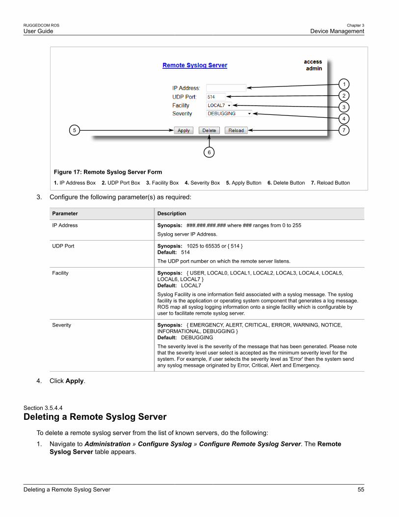
RUGGEDCOM ROSUser Guide
Chapter 3Device Management
Deleting a Remote Syslog Server 55
75
6
4
3
2
1
Figure 17: Remote Syslog Server Form
1. IP Address Box 2. UDP Port Box 3. Facility Box 4. Severity Box 5. Apply Button 6. Delete Button 7. Reload Button
3. Configure the following parameter(s) as required:
Parameter Description
IP Address Synopsis: ###.###.###.### where ### ranges from 0 to 255
Syslog server IP Address.
UDP Port Synopsis: 1025 to 65535 or { 514 }Default: 514
The UDP port number on which the remote server listens.
Facility Synopsis: { USER, LOCAL0, LOCAL1, LOCAL2, LOCAL3, LOCAL4, LOCAL5,LOCAL6, LOCAL7 }Default: LOCAL7
Syslog Facility is one information field associated with a syslog message. The syslogfacility is the application or operating system component that generates a log message.ROS map all syslog logging information onto a single facility which is configurable byuser to facilitate remote syslog server.
Severity Synopsis: { EMERGENCY, ALERT, CRITICAL, ERROR, WARNING, NOTICE,INFORMATIONAL, DEBUGGING }Default: DEBUGGING
The severity level is the severity of the message that has been generated. Please notethat the severity level user select is accepted as the minimum severity level for thesystem. For example, if user selects the severity level as 'Error' then the system sendany syslog message originated by Error, Critical, Alert and Emergency.
4. Click Apply.
Section 3.5.4.4
Deleting a Remote Syslog ServerTo delete a remote syslog server from the list of known servers, do the following:
1. Navigate to Administration » Configure Syslog » Configure Remote Syslog Server. The RemoteSyslog Server table appears.

Chapter 3Device Management
RUGGEDCOM ROSUser Guide
56 Managing Ethernet Ports
Figure 18: Remote Syslog Server Table
2. Select the server from the table. The Remote Syslog Server form appears.
75
6
4
3
2
1
Figure 19: Remote Syslog Server Form
1. IP Address Box 2. UDP Port Box 3. Facility Box 4. Severity Box 5. Apply Button 6. Delete Button 7. Reload Button
3. Click Delete.
Section 3.6
Managing Ethernet PortsThe following sections describe how to set up and manage Ethernet ports:
NOTEFor information about configuring remote monitoring for Ethernet ports, refer to Section 3.10,“Managing Remote Monitoring”.
• Section 3.6.1, “Controller Protection Through Link Fault Indication (LFI)”
• Section 3.6.2, “Viewing the Status of Ethernet Ports”
• Section 3.6.3, “Viewing Statistics for All Ethernet Ports”
• Section 3.6.4, “Viewing Statistics for Specific Ethernet Ports”
• Section 3.6.5, “Clearing Statistics for Specific Ethernet Ports”
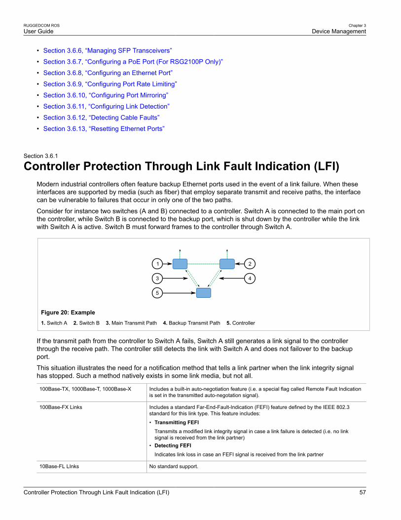
RUGGEDCOM ROSUser Guide
Chapter 3Device Management
Controller Protection Through Link Fault Indication (LFI) 57
• Section 3.6.6, “Managing SFP Transceivers”
• Section 3.6.7, “Configuring a PoE Port (For RSG2100P Only)”
• Section 3.6.8, “Configuring an Ethernet Port”
• Section 3.6.9, “Configuring Port Rate Limiting”
• Section 3.6.10, “Configuring Port Mirroring”
• Section 3.6.11, “Configuring Link Detection”
• Section 3.6.12, “Detecting Cable Faults”
• Section 3.6.13, “Resetting Ethernet Ports”
Section 3.6.1
Controller Protection Through Link Fault Indication (LFI)Modern industrial controllers often feature backup Ethernet ports used in the event of a link failure. When theseinterfaces are supported by media (such as fiber) that employ separate transmit and receive paths, the interfacecan be vulnerable to failures that occur in only one of the two paths.
Consider for instance two switches (A and B) connected to a controller. Switch A is connected to the main port onthe controller, while Switch B is connected to the backup port, which is shut down by the controller while the linkwith Switch A is active. Switch B must forward frames to the controller through Switch A.
21
5
3 4
Figure 20: Example
1. Switch A 2. Switch B 3. Main Transmit Path 4. Backup Transmit Path 5. Controller
If the transmit path from the controller to Switch A fails, Switch A still generates a link signal to the controllerthrough the receive path. The controller still detects the link with Switch A and does not failover to the backupport.
This situation illustrates the need for a notification method that tells a link partner when the link integrity signalhas stopped. Such a method natively exists in some link media, but not all.
100Base-TX, 1000Base-T, 1000Base-X Includes a built-in auto-negotiation feature (i.e. a special flag called Remote Fault Indicationis set in the transmitted auto-negotation signal).
100Base-FX Links Includes a standard Far-End-Fault-Indication (FEFI) feature defined by the IEEE 802.3standard for this link type. This feature includes:
• Transmitting FEFITransmits a modified link integrity signal in case a link failure is detected (i.e. no linksignal is received from the link partner)
• Detecting FEFIIndicates link loss in case an FEFI signal is received from the link partner
10Base-FL LInks No standard support.

Chapter 3Device Management
RUGGEDCOM ROSUser Guide
58 Viewing the Status of Ethernet Ports
10Base-FL links do not have a native link partner notification mechanism and FEFI support in 100Base-FX linksis optional according to the IEEE 802.3 standard, which means that some links partners may not support it.
Siemens offers an advanced Link-Fault-Indication (LFI) feature for the links that do not have a native link partnernotification mechanism. With LFI enabled, the device bases the generation of a link integrity signal upon itsreception of a link signal. In the example described previously, if switch A fails to receive a link signal from thecontroller, it will stop generating a link signal. The controller will detect the link failure and failover to the backkupport.
IMPORTANT!If both link partners have the LFI feature, it must not be enabled on both sides of the link. If it is enabledon both sides, the link will never be established, as each link partner will be waiting for the other totransmit a link signal.
The switch can also be configured to flush the MAC address table for the controller port. Frames destined for thecontroller will be flooded to Switch B where they will be forwarded to the controller (after the controller transmitsits first frame).
Section 3.6.2
Viewing the Status of Ethernet PortsTo view the current status of each Ethernet port, navigate to Ethernet Ports » View Port Status. The PortStatus table appears.
Figure 21: Port Status Table
This table displays the following information:
Parameter Description
Port Synopsis: 1 to maximum port number
The port number as seen on the front plate silkscreen of the switch.
Name Synopsis: Any 15 characters
A descriptive name that may be used to identify the device conected on that port.
Link Synopsis: { ----, ----, Down, Up }
The port's link status.
Speed Synopsis: { ---, 10M, 100M, 1G, 10G }

RUGGEDCOM ROSUser Guide
Chapter 3Device Management
Viewing Statistics for All Ethernet Ports 59
Parameter Description
The port's current speed.
Duplex Synopsis: { ----, Half, Full }
The port's current duplex status.
Section 3.6.3
Viewing Statistics for All Ethernet PortsTo view statistics collected for all Ethernet ports, navigate to Ethernet Stats » View Ethernet Statistics. TheEthernet Statistics table appears.
Figure 22: Ethernet Statistics Table
This table displays the following information:
Parameter Description
Port Synopsis: 1 to maximum port number
The port number as seen on the front plate silkscreen of the switch.
State Synopsis: { ----, ----, Down, Up }
InOctets Synopsis: 0 to 4294967295
The number of octets in received good packets (Unicast+Multicast+Broadcast) and droppedpackets.
OutOctets Synopsis: 0 to 4294967295
The number of octets in transmitted good packets.
InPkts Synopsis: 0 to 4294967295
The number of received good packets (Unicast+Multicast+Broadcast) and dropped packets.
OutPkts Synopsis: 0 to 4294967295
The number of transmitted good packets.
ErrorPkts Synopsis: 0 to 4294967295
The number of any type of erroneous packet.

Chapter 3Device Management
RUGGEDCOM ROSUser Guide
60 Viewing Statistics for Specific Ethernet Ports
Section 3.6.4
Viewing Statistics for Specific Ethernet PortsTo view statistics collected for specific Ethernet ports, navigate to Ethernet Stats » View Ethernet PortStatistics. The Ethernet Port Statistics table appears.
Figure 23: Ethernet Port Statistics Table
This table displays the following information:
Parameter Description
Port Synopsis: 1 to maximum port number
The port number as seen on the front plate silkscreen of the switch.
InOctets Synopsis: 0 to 18446744073709551615
The number of octets in received good packets (Unicast+Multicast+Broadcast) and droppedpackets.
OutOctets Synopsis: 0 to 18446744073709551615
The number of octets in transmitted good packets.
InPkts Synopsis: 0 to 18446744073709551615
The number of received good packets (Unicast+Multicast+Broadcast) and dropped packets.
OutPkts Synopsis: 0 to 18446744073709551615
The number of transmitted good packets.
TotalInOctets Synopsis: 0 to 18446744073709551615
The total number of octets of all received packets. This includes data octets of rejected andlocal packets which are not forwarded to the switching core for transmission. It should reflectall the data octets received on the line.
TotalInPkts Synopsis: 0 to 18446744073709551615
The number of received packets. This includes rejected, dropped local, and packetswhich are not forwarded to the switching core for transmission. It should reflect all packetsreceived ont the line.
InBroadcasts Synopsis: 0 to 18446744073709551615
The number of good Broadcast packets received.
InMulticasts Synopsis: 0 to 18446744073709551615
The number of good Multicast packets received.
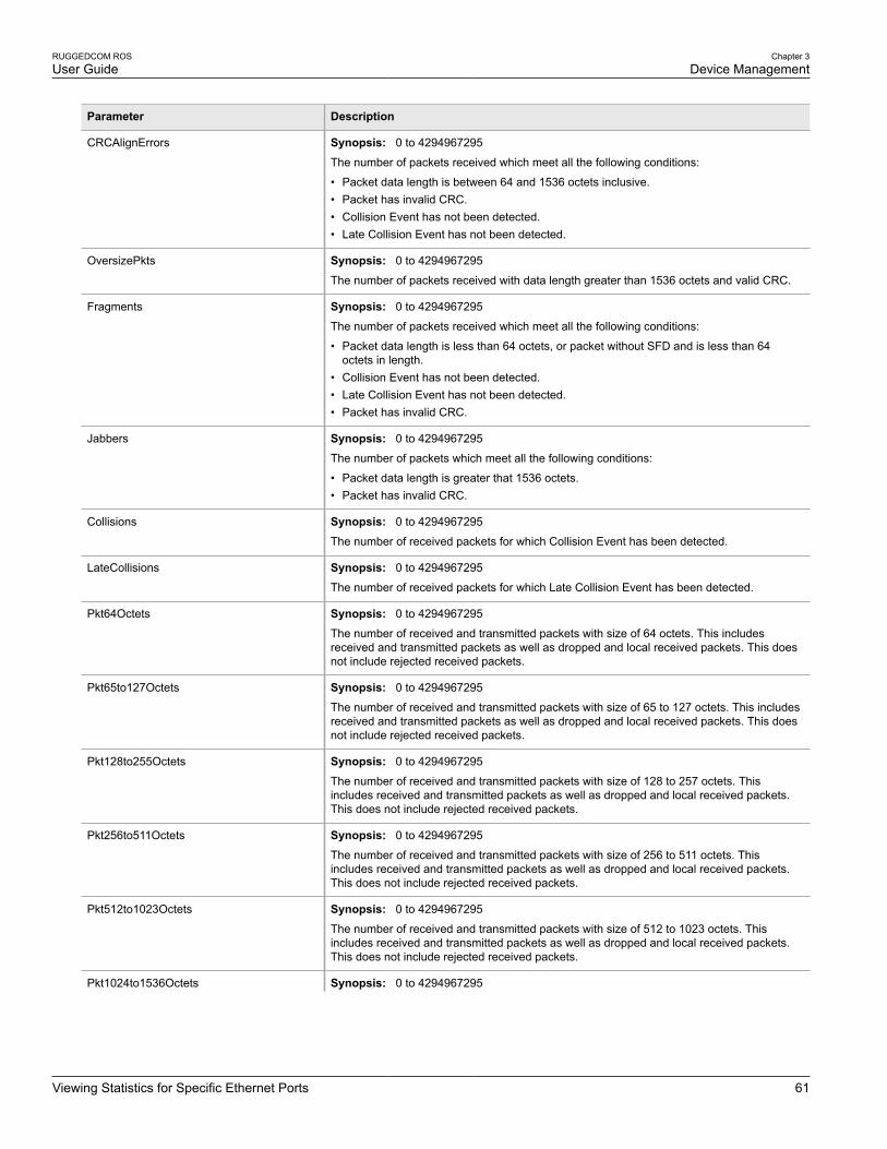
RUGGEDCOM ROSUser Guide
Chapter 3Device Management
Viewing Statistics for Specific Ethernet Ports 61
Parameter Description
CRCAlignErrors Synopsis: 0 to 4294967295
The number of packets received which meet all the following conditions:
• Packet data length is between 64 and 1536 octets inclusive.• Packet has invalid CRC.• Collision Event has not been detected.• Late Collision Event has not been detected.
OversizePkts Synopsis: 0 to 4294967295
The number of packets received with data length greater than 1536 octets and valid CRC.
Fragments Synopsis: 0 to 4294967295
The number of packets received which meet all the following conditions:
• Packet data length is less than 64 octets, or packet without SFD and is less than 64octets in length.
• Collision Event has not been detected.• Late Collision Event has not been detected.• Packet has invalid CRC.
Jabbers Synopsis: 0 to 4294967295
The number of packets which meet all the following conditions:
• Packet data length is greater that 1536 octets.• Packet has invalid CRC.
Collisions Synopsis: 0 to 4294967295
The number of received packets for which Collision Event has been detected.
LateCollisions Synopsis: 0 to 4294967295
The number of received packets for which Late Collision Event has been detected.
Pkt64Octets Synopsis: 0 to 4294967295
The number of received and transmitted packets with size of 64 octets. This includesreceived and transmitted packets as well as dropped and local received packets. This doesnot include rejected received packets.
Pkt65to127Octets Synopsis: 0 to 4294967295
The number of received and transmitted packets with size of 65 to 127 octets. This includesreceived and transmitted packets as well as dropped and local received packets. This doesnot include rejected received packets.
Pkt128to255Octets Synopsis: 0 to 4294967295
The number of received and transmitted packets with size of 128 to 257 octets. Thisincludes received and transmitted packets as well as dropped and local received packets.This does not include rejected received packets.
Pkt256to511Octets Synopsis: 0 to 4294967295
The number of received and transmitted packets with size of 256 to 511 octets. Thisincludes received and transmitted packets as well as dropped and local received packets.This does not include rejected received packets.
Pkt512to1023Octets Synopsis: 0 to 4294967295
The number of received and transmitted packets with size of 512 to 1023 octets. Thisincludes received and transmitted packets as well as dropped and local received packets.This does not include rejected received packets.
Pkt1024to1536Octets Synopsis: 0 to 4294967295

Chapter 3Device Management
RUGGEDCOM ROSUser Guide
62 Clearing Statistics for Specific Ethernet Ports
Parameter Description
The number of received and transmitted packets with size of 1024 to 1536 octets. Thisincludes received and transmitted packets as well as dropped and local received packets.This does not include rejected received packets.
DropEvents Synopsis: 0 to 4294967295
The number of received packets that are droped due to lack of receive buffers.
OutMulticasts Synopsis: 0 to 18446744073709551615
The number of transmitted Multicast packets. This does not include Broadcast packets.
OutBroadcasts Synopsis: 0 to 18446744073709551615
The number of transmitted Broadcast packets.
UndersizePkts Synopsis: 0 to 4294967295
The number of received packets which meet all the following conditions:
• Packet data length is less than 64 octets.• Collision Event has not been detected.• Late Collision Event has not been detected.• Packet has valid CRC.
Section 3.6.5
Clearing Statistics for Specific Ethernet PortsTo clear the statistics collected for one or more Ethernet ports, do the following:
1. Navigate to Ethernet Stats » Clear Ethernet Port Statistics. The Clear Ethernet Port Statistics formappears.
1
2
Figure 24: Clear Ethernet Port Statistics Form (Typical)
1. Port Check Boxes 2. Confirm Button
2. Select one or more Ethernet ports.
3. Click Confirm.
Section 3.6.6
Managing SFP TransceiversROS supports Small Form Factor Pluggable (SFP) transceivers to provide a 1000Base-X, 1000Base-T link or100Base-TX.

RUGGEDCOM ROSUser Guide
Chapter 3Device Management
Configuring an SFP Port 63
NOTESince 1000Base-X fiber SFP transceivers are standardized, ROS supports any model of this type. Itis strongly recommended to use SFP transceiver models offered by Siemens only. Siemens performsextensive testing on the transceivers in harsh conditions. If a different SFP transceiver model is used, itis the user’s responsibility to verify it meets environmental and usage requirements.
1000Base-T copper SFP transceivers are not standardized. ROS supports only selected models of thistype.
The following sections describe how to configure and manage SFP transceivers:
• Section 3.6.6.1, “Configuring an SFP Port”
• Section 3.6.6.2, “Monitoring an SFP Port”
• Section 3.6.6.3, “Displaying Information for an SFP Port”
Section 3.6.6.1
Configuring an SFP PortDepending on the required link media type, an SFP port may require some explicit configuration:
• For 1000Base-X or 1000Base-T links, the speed of the SFP port must be set to 1 Gbps.
• For 100Base-TX links, the speed must be set to 100 Mbps.
• Auto-negotiation can be configured to On when the port speed is set to 1 Gbps, or to Off when the port speedis set to 100 Mbps.
• Duplex mode cannot be configured on an SFP port and is always forced to full duplex.
For more information about configuring SFP transceiver ports and other Ethernet ports on the device, refer toSection 3.6.8, “Configuring an Ethernet Port”.
Section 3.6.6.2
Monitoring an SFP PortROS supports hot-swapping of SFP transceivers on SFP ports and will automatically detect when an SFPtransceiver is removed or installed.
When ROS detects that an SFP transceiver is plugged into an SFP port, it reads the transceiver information anddetermines the transceiver type. This decision results in ROS either accepting, accepting and reconfiguring, orrejecting the SFP port.
The following table shows in which cases an SFP transceiver is accepted or accepted and reconfigured.
Configured Speed Detected SFP Type: 1000Base-X Detected SFP Type: 1000Base-T
1 Gbps Accept Accept
100 Mbps Accept and automatically set the speedto 1 Gbps and set auto-negotiation to On
Compare the transceiver model against alist of supported models. Accept if it is in thelist. Otherwise, automatically set the speedto 1 Gbps and set auto-negotiation to On.
If the transceiver is accepted, the Media parameter under Ethernet Ports » Configure Port Parameters showsdetailed information about the SFP transceiver, including Gigabit Ethernet Compliance Code, transmission media,connector type, and link length. For example:

Chapter 3Device Management
RUGGEDCOM ROSUser Guide
64 Displaying Information for an SFP Port
SFP 1000LX SM LC 10 kmSFP 1000T 100 m
If the transceiver is not recognized, it is rejected. An alarm is also generated and the port is blocked so thatno link can be established until the transceiver is replaced. The Media parameter shows the rejected SFPtransceiver is unidentified. For example:
SFP Unidentified
If no transceiver is installed on an SFP port, the Media parameter shows the SFP transceiver is unplugged:
SFP Unplugged
Section 3.6.6.3
Displaying Information for an SFP PortTo display detailed information about an SFP port, do the following:
1. Log in to the device and access the CLI shell. For more information about accessing the CLI shell, refer toSection 2.6, “Using the Command Line Interface”.
2. Type the following command:
sfp port
Where:
• port is the port number
Information about the SFP port is displayed. For example:
>sfp 11/1ID: SFPExtended ID: GBIC/SFP function is defined by serial ID onlyConnector: LCTransceiver:Gigabit Ethernet Compliance Codes:1000LXFibre Channel link length:Long Distance (L)Fibre Channel transmitter technology:Longwave laser (LC)Fibre Channel transmission media:Single Mode (SM)Fibre Channel speed:100 MBytes/SecBaud Rate, nominal: 1300 MBits/secEncoding type: 8B10BLength(9um): 10 kmLength(9um): 10000 mLength(50um): 550 mLength(62.5um): 550 mLength(Copper): Not specifiedVendor: xxxxxxxIEEE company ID: xxxxxxxPart number: xxxxxxxxxxRevision: 0000Laser wavelength: 1310 nm>

RUGGEDCOM ROSUser Guide
Chapter 3Device Management
Configuring a PoE Port (For RSG2100P Only) 65
Section 3.6.7
Configuring a PoE Port (For RSG2100P Only)To configure Power-over-Ethernet (PoE) settings for a specific Ethernet port, do the following:
1. Navigate to Ethernet Ports » Configure/View PoE Parameters » Configure/View Port PoE Parameters.The Port PoE Parameters table appears.
Figure 25: Port PoE Parameters Table
2. Select an Ethernet port. The Port PoE Parameters form appears.
87
6
5
4
3
2
1
Figure 26: Port PoE Parameters Form
1. Port Box 2. Admin Options 3. Powered Box 4. Class Box 5. Voltage Box 6. Current Box 7. Apply Button 8. ReloadButton
3. Configure the following parameter(s) as required:
Parameter Description
Port Synopsis: 1 to maximum port numberDefault: 1The port number as seen on the front plate silkscreen of the switch.
Admin Synopsis: { Disabled, Enabled }Default: Enabled
This parameter allows to enable or disable supplying power by the port.
Powered Synopsis: { No, Yes }
Whether or not power is currently supplied by the port.
Class Synopsis: 0 to 65535

Chapter 3Device Management
RUGGEDCOM ROSUser Guide
66 Configuring an Ethernet Port
Parameter Description
PoE Class value that defines the minimum supplied power level. For more information,refer to the IEEE 802.1af and 802.1at standards.
0 = 15.4 W (default)
1 = 4.0 W
2 = 7.0 W
3 = 15.4 W
4 = 34.2 W
Pwr Limit Synopsis: 0 to 6554
Power level corresponding to the PoE Class determined for the port.
Voltage Synopsis: 0 to 65535
Supplied voltage level.
Current Synopsis: 0 to 65535
Supplied current level.
4. Click Apply.
Section 3.6.8
Configuring an Ethernet PortTo configure an Ethernet port, do the following:
NOTEDepending on the required link media type, an SFP port may require some explicit configuration.Before configuring an SFP port, refer to Section 3.6.6.1, “Configuring an SFP Port”.
1. Navigate to Ethernet Ports » Configure Port Parameters. The Port Parameters table appears.
Figure 27: Port Parameters Table
2. Select an Ethernet port. The Port Parameters form appears.

RUGGEDCOM ROSUser Guide
Chapter 3Device Management
Configuring an Ethernet Port 67
7
11
6
5
4
3
2
1
8
12
9
10
Figure 28: Port Parameters Form
1. Port Box 2. Name Box 3. Media Box 4. State Box 5. AutoN Box 6. Speed Box 7. Dupx Box 8. FlowCtrl Box 9. LFIBox 10. Alarm Box 11. Apply Button 12. Reload Button
3. Configure the following parameter(s) as required:
Parameter Description
Port Synopsis: 1 to maximum port numberDefault: 1The port number as seen on the front plate silkscreen of the switch.
Name Synopsis: Any 15 charactersDefault: Port x
A descriptive name that may be used to identify the device connected on that port.
Media Synopsis: { 100TX, 10FL, 100FX, 1000X, 1000T, 802.11g, EoVDSL, 100TX Only,10FL/100SX, 10GX }Default: 100TX
The type of the port media.
State Synopsis: { Disabled, Enabled }Default: Enabled
Disabling a port will prevent all frames from being sent and received on that port. Also,when disabled link integrity signal is not sent so that the link/activity LED will never belit. You may want to disable a port for troubleshooting or to secure it from unauthorizedconnections.
NOTEDisabling a port whose media type is set to 802.11g disables thecorresponding wireless module.
AutoN Synopsis: { Off, On }Default: On
Enable or disable IEEE 802.3 auto-negotiation. Enabling auto-negotiation results inspeed and duplex being negotiated upon link detection; both end devices must be auto-negotiation compliant for the best possible results. 10Mbps and 100Mbps fiber optic

Chapter 3Device Management
RUGGEDCOM ROSUser Guide
68 Configuring an Ethernet Port
Parameter Description
media do not support auto-negotiation so these media must be explicitly configured toeither half or full duplex. Full duplex operation requires that both ends are configured assuch or else severe frame loss will occur during heavy network traffic.
Speed Synopsis: { Auto, 10M, 100M, 1G }Default: Auto
Speed (in Megabit-per-second or Gigabit-per-second). If auto-negotiation is enabled,this is the speed capability advertised by the auto-negotiation process. If auto-negotiation is disabled, the port is explicitly forced to this speed mode.
AUTO means advertise all supported speed modes.
Dupx Synopsis: { Auto, Half, Full }Default: Auto
Duplex mode. If auto-negotiation is enabled, this is the duplex capability advertised bythe auto-negotiation process. If auto-negotiation is disabled, the port is explicitly forcedto this duplex mode.
AUTO means advertise all supported duplex modes.
Flow Control Synopsis: { Off, On }Default: On
Flow Control is useful for preventing frame loss during times of severe network traffic.Examples of this include multiple source ports sending to a single destination port or ahigher speed port bursting to a lower speed port.
When the port is half-duplex it is accomplished using 'backpressure' where the switchsimulates collisions causing the sending device to retry transmissions according to theEthernet backoff algorithm.
When the port is full-duplex it is accomplished using PAUSE frames which causes thesending device to stop transmitting for a certain period of time.
LFI Synopsis: { Off, On }Default: Off
Enabling Link-Fault-Indication (LFI) inhibits transmitting link integrity signal when thereceive link has failed. This allows the device at far end to detect link failure under allcircumstances.
NOTEThis feature must not be enabled at both ends of a fiber link.
Alarm Synopsis: { On, Off }Default: On
Disabling link state alarms will prevent alarms and LinkUp and LinkDown SNMP trapsfrom being sent for that port.
NOTEIf one end of the link is fixed to a specific speed and duplex type and the peer auto-negotiates,there is a strong possibility that the link will either fail to raise, or raise with the wrong settings onthe auto-negotiating side. The auto-negotiating peer will fall back to half-duplex operation, evenwhen the fixed side is full duplex. Full-duplex operation requires that both ends are configuredas such or else severe frame loss will occur during heavy network traffic. At lower traffic volumesthe link may display few, if any, errors. As the traffic volume rises, the fixed negotiation side willbegin to experience dropped packets, while the auto-negotiating side will experience excessivecollisions. Ultimately, as traffic load approaches 100%, the link will become entirely unusable.These problems can be avoided by always configuring ports to the appropriate fixed values.
4. Click Apply.
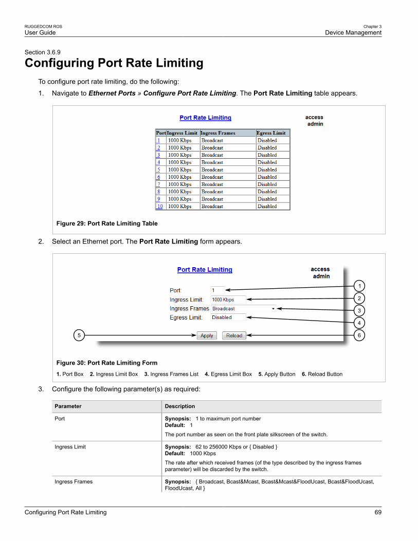
RUGGEDCOM ROSUser Guide
Chapter 3Device Management
Configuring Port Rate Limiting 69
Section 3.6.9
Configuring Port Rate LimitingTo configure port rate limiting, do the following:
1. Navigate to Ethernet Ports » Configure Port Rate Limiting. The Port Rate Limiting table appears.
Figure 29: Port Rate Limiting Table
2. Select an Ethernet port. The Port Rate Limiting form appears.
65
4
3
2
1
Figure 30: Port Rate Limiting Form
1. Port Box 2. Ingress Limit Box 3. Ingress Frames List 4. Egress Limit Box 5. Apply Button 6. Reload Button
3. Configure the following parameter(s) as required:
Parameter Description
Port Synopsis: 1 to maximum port numberDefault: 1The port number as seen on the front plate silkscreen of the switch.
Ingress Limit Synopsis: 62 to 256000 Kbps or { Disabled }Default: 1000 Kbps
The rate after which received frames (of the type described by the ingress framesparameter) will be discarded by the switch.
Ingress Frames Synopsis: { Broadcast, Bcast&Mcast, Bcast&Mcast&FloodUcast, Bcast&FloodUcast,FloodUcast, All }

Chapter 3Device Management
RUGGEDCOM ROSUser Guide
70 Configuring Port Mirroring
Parameter Description
Default: Broadcast
This parameter specifies the types of frames to be rate-limited on this port. It appliesonly to received frames:
• Broadcast - only broadcast frames• Bcast&Mcast - broadcast and multicast frames• Bcast&FloodUcast - broadcast and flooded unicast frames• Bcast&Mcast&FloodUcast - broadcast, multicast and flooded unicast frames• FloodUcast - only flooded unicast frames• All - all (multicast, broadcast and unicast) frames
Egress Limit Synopsis: { Broadcast, Multicast, Mcast&FloodUcast, All }">62 to 256000 Kbps or{ Disabled }Default: Disabled
The maximum rate at which the switch will transmit (multicast, broadcast and unicast)frames on this port. The switch will discard frames in order to meet this rate if required.
4. Click Apply.
Section 3.6.10
Configuring Port MirroringPort mirroring is a troubleshooting tool that copies, or mirrors, all traffic received or transmitted on a designatedport to specified mirror port. If a protocol analyzer is attached to the target port, the traffic stream of valid frameson any source port is made available for analysis.
Select a target port that has a higher speed than the source port. Mirroring a 100 Mbps port onto a 10 Mbps portmay result in an improperly mirrored stream.
Frames will be dropped if the full-duplex rate of frames on the source port exceeds the transmission speed of thetarget port. Since both transmitted and received frames on the source port are mirrored to the target port, frameswill be discarded if the sum traffic exceeds the target port’s transmission rate. This problem reaches its extreme inthe case where traffic on a 100 Mbps full-duplex port is mirrored onto a 10 Mbps half-duplex port.
NOTEInvalid frames received on the source port will not be mirrored. These include CRC errors, oversizeand undersize packets, fragments, jabbers, collisions, late collisions and dropped events.
IMPORTANT!Before configuring port mirroring, note the following limitations:
• Traffic will be mirrored onto the target port irrespective of its VLAN membership. It could be the sameas or different from the source port's membership
• Network management frames (such as RSTP, GVRP etc.) may not be mirrored
• Switch management frames generated by the switch (such as Telnet, HTTP, SNMP, etc.) may not bemirrored
To configure port mirroring, do the following:
1. Navigate to Ethernet Ports » Configure Port Mirroring. The Port Mirroring form appears.

RUGGEDCOM ROSUser Guide
Chapter 3Device Management
Configuring Link Detection 71
5 6
4
3
2
1
Figure 31: Port Mirroring Form
1. Port Mirroring Box 2. Source Port Box 3. Target Port Box 4. Apply Button 5. Reload Button
2. Configure the following parameter(s) as required:
Parameter Description
Port Mirroring Synopsis: { Disabled, Enabled }Default: Disabled
Enabling port mirroring causes all frames received and transmitted by the source port(s)to be transmitted out of the target port.
Source Port Synopsis: Any combination of numbers valid for this parameter
The port(s) being monitored.
Source Direction Synopsis: Egress and Ingress, Egress OnlyDefault: Egress and Ingress
Specifies monitoring whether both egress and ingress traffics or only egress traffic of thesource port.
Target Port Synopsis: 1 to maximum port numberDefault: 1The port where a monitoring device should be connected.
3. Click Apply.
Section 3.6.11
Configuring Link DetectionTo configure link detection, do the following:
1. Navigate to Ethernet Ports » Configure Link Detection. The Link Detection form appears.

Chapter 3Device Management
RUGGEDCOM ROSUser Guide
72 Configuring Link Detection
43
2
1
Figure 32: Link Detection Form
1. Fast Link Detection Box 2. Link Detection Time Box 3. Apply Button 4. Reload Button
2. Configure the following parameter(s) as required:
NOTEWhen Fast Link Detection is enabled, the system prevents link state change processing fromconsuming all available CPU resources. However, if Port Guard is not used, it is possible foralmost all available CPU time to be consumed by frequent link state changes, which could have anegative impact on overall system responsiveness.
Parameter Description
Fast Link Detection Synopsis: { Off, On, On_withPortGuard }Default: On_withPortGuard
This parameter provides protection against faulty end devices generating an improperlink integrity signal. When a faulty end device or a mis-matching fiber port is connectedto the unit, a large number of continuous link state changes could be reported in a shortperiod of time. These large number of bogus link state changes could render the systemunresponsive as most, if not all, of the system resources are used to process the linkstate changes. This could in turn cause a serious network problem as the unit's RSTPprocess may not be able to run, thus allowing network loop to form.
Three different settings are available for this parameter:
• ON_withPortGuard - This is the recommended setting. With this setting, an extendedperiod (~2 minutes) of excessive link state changes reported by a port will prompt PortGuard feature to disable FAST LINK DETECTION on that port and raise an alarm.By disabling FAST LINK DETECTION on the problematic port, excessive link statechanges can no longer consume substantial amount of system resources. However ifFAST LINK DETECTION is disabled, the port will need a longer time to detect a linkfailure. This may result in a longer network recovery time of up to 2s. Once Port Guarddisables FAST LINK DETECTION of a particular port, user can re-enable FAST LINKDETECTION on the port by clearing the alarm.
• ON - In certain special cases where a prolonged excessive link state changesconstitute a legitimate link operation, using this setting can prevent Port Guard fromdisabling FAST LINK DETECTION on the port in question. If excessive link statechanges persist for more than 2 minutes, an alarm will be generated to warn userabout the observed bouncing link. If the excessive link state changes condition isresolved later on, the alarm will be cleared automatically. Since this option does notdisable FAST LINK DETECTION, a persistent bouncing link could continue affect thesystem in terms of response time. This setting should be used with caution.
• OFF - Turning this parameter OFF will disable FAST LINK DETECTION completely.The switch will need a longer time to detect a link failure. This will result in a longernetwork recovery time of up to 2s.
Link Detection Time Synopsis: 100 ms to 1000 msDefault: 100 ms

RUGGEDCOM ROSUser Guide
Chapter 3Device Management
Detecting Cable Faults 73
Parameter Description
The time that the link has to continuously stay up before the "link up" decision is madeby the device.
(The device performs de-bouncing of Ethernet link detection to avoid multiple responsesto an occasional link bouncing event, e.g. when a cable is shaking while being plugged-in or unplugged).
3. Click Apply.
Section 3.6.12
Detecting Cable FaultsConnectivity issues can sometimes be attributed to faults in Ethernet cables. To help detect cable faults, shortcircuits, open cables or cables that are too long, ROS includes a built-in cable diagnostics utility.
The following sections describe how to run diagnostics on Ethernet cables:
• Section 3.6.12.1, “Viewing Cable Diagnostics Results”
• Section 3.6.12.2, “Performing Cable Diagnostics”
• Section 3.6.12.3, “Clearing Cable Diagnostics”
• Section 3.6.12.4, “Determining the Estimated Distance To Fault (DTF)”
Section 3.6.12.1
Viewing Cable Diagnostics ResultsTo view the results of previous diagnostic tests, navigate to Ethernet Ports » Configure/View CableDiagnostics Parameters. The Cable Diagnostics Parameters table appears.
NOTEFor information about how to start a diagnostic test, refer to Section 3.6.12.2, “Performing CableDiagnostics”.
Figure 33: Cable Diagnostics Parameters Table
This table displays the following information:

Chapter 3Device Management
RUGGEDCOM ROSUser Guide
74 Viewing Cable Diagnostics Results
Parameter Description
Port Synopsis: 1 to maximum port number
The port number as seen on the front plate silkscreen of the switch.
State Synopsis: { Stopped, Started }
Control the start/stop of the cable diagnostics on the selected port. If a port does not supportcable diagnostics, State will be reported as N/A.
Runs Synopsis: 0 to 65535
The total number of times cable diagnostics to be performed on the selected port. If thisnumber is set to 0, cable diagnostics will be performed forever on the selected port.
Calib. Synopsis: -100.0 to 100.0 m
This calibration value can be used to adjust or calibrate the estimated distance to fault. Usercan take following steps to calibrate the cable diagnostics estimated distance to fault:
• Pick a particular port which calibration is needed• Connect an Ethernet cable with a known length (e.g. 50m) to the port• DO NOT connect the other end of the cable to any link partner• Run cable diagnostics a few times on the port. OPEN fault should be detected• Find the average distance to the OPEN fault recorded in the log and compare it to the
known length of the cable. The difference can be used as the calibration value• Enter the calibration value and run cable diagnostics a few more times• The distance to OPEN fault should now be at similar distance as the cable length• Distance to fault for the selected port is now calibrated
Good Synopsis: 0 to 65535
The number of times GOOD TERMINATION (no fault) is detected on the cable pairs of theselected port.
Open Synopsis: 0 to 65535
The number of times OPEN is detected on the cable pairs of the selected port.
Short Synopsis: 0 to 65535
The number of times SHORT is detected on the cable pairs of the selected port.
Imped Synopsis: 0 to 65535
The number of times IMPEDANCE MISMATCH is detected on the cable pairs of theselected port.
Pass /Fail /Total Synopsis: Any 19 characters
This field summarizes the results of the cable diagnostics performed so far.
Pass - number of times cable diagnostics successfully completed on the selected port.
Fail - number of times cable diagnostics failed to complete on the selected port.
Total - total number of times cable diagnostics have been attempted on the selected port.
>
NOTEFor each successful diagnostic test, the values for Good, Open, Short or Imped will increment basedon the number of cable pairs connected to the port. For a 100Base-T port, which has two cable pairs,the number will increase by two. For a 1000Base-T port, which has four cable pairs, the number willincrease by four.

RUGGEDCOM ROSUser Guide
Chapter 3Device Management
Performing Cable Diagnostics 75
NOTEWhen a cable fault is detected, an estimated distance-to-fault is calculated and recorded in the systemlog. The log lists the cable pair, the fault that was detected, and the distance-to-fault value. For moreinformation about the system log, refer to Section 3.5.1, “Viewing Local Logs”.
Section 3.6.12.2
Performing Cable DiagnosticsTo perform a cable diagnostic test on one or more Ethernet ports, do the following:
1. Connect a CAT-5 (or better quality) Ethernet cable to the selected Ethernet port.
IMPORTANT!Both the selected Ethernet port and its partner port can be configured to run in Enabled mode withauto-negotiation, or in Disabled mode. Other modes are not recommended, as they may interferewith the cable diagnostics procedure.
2. Connect the other end of the cable to a similar network port. For example, connect a 100Base-T port to a100Base-T port, or a 1000Base-T port to a 1000Base-T port.
3. In ROS, navigate to Ethernet Ports » Configure/View Cable Diagnostics Parameters. The CableDiagnostics Parameters table appears.
Figure 34: Cable Diagnostics Parameters Table
4. Select an Ethernet port. The Cable Diagnostics Parameters form appears.

Chapter 3Device Management
RUGGEDCOM ROSUser Guide
76 Clearing Cable Diagnostics
1110
9
8
7
6
5
4
3
2
1
Figure 35: Cable Diagnostics Parameters Form
1. Port Box 2. State Options 3. Runs Box 4. Calib. Box 5. Good Box 6. Open Box 7. Short Box 8. Imped Box 9. Pass /Fail /Total Box 10. Apply Button 11. Reload Button
5. Under Runs, enter the number of consecutive diagnostic tests to perform. A value of 0 indicates the test willrun continuously until stopped by the user.
6. Under Calib., enter the estimated Distance To Fault (DTF) value. For information about how to determine theDTF value, refer to Section 3.6.12.4, “Determining the Estimated Distance To Fault (DTF)”.
7. Select Started.
IMPORTANT!A diagnostic test can be stopped by selecting Stopped and clicking Apply. However, if the test isstopped in the middle of a diagnostic run, the test will run to completion.
8. Click Apply. The state of the Ethernet port will automatically change to Stopped when the test is complete.For information about how to monitor the test and view the results, refer to Section 3.6.12.1, “Viewing CableDiagnostics Results”.
Section 3.6.12.3
Clearing Cable DiagnosticsTo clear the cable diagnostic results, do the following:
1. Navigate to Ethernet Ports » Clear Cable Diagnostics Statistics. The Clear Cable Diagnostics Statisticsform appears.

RUGGEDCOM ROSUser Guide
Chapter 3Device Management
Determining the Estimated Distance To Fault (DTF) 77
1
2
Figure 36: Clear Cable Diagnostics Statistics Form
1. Port Check Boxes 2. Apply Button
2. Select one or more Ethernet ports.
3. Click Apply.
Section 3.6.12.4
Determining the Estimated Distance To Fault (DTF)To determine the estimate Distance To Fault (DTF), do the following:
1. Connect a CAT-5 (or better quality) Ethernet cable with a known length to the device. Do not connect theother end of the cable to another port.
2. Configure the cable diagnostic utility to run a few times on the selected Ethernet port and start the test. Formore information, refer to Section 3.6.12.2, “Performing Cable Diagnostics”. Open faults should be detectedand recorded in the system log.
3. Review the errors recorded in the system log and determine the average distance of the open faults. Formore information about the system log, refer to Section 3.5.1, “Viewing Local Logs”.
4. Subtract the average distance from the cable length to determine the calibration value.
5. Configure the cable diagnostic utility to run a few times with the new calibration value. The distance to theopen fault should now be the same as the actual length of the cable. The Distance To Fault (DTF) is nowcalibrated for the selected Ethernet port.
Section 3.6.13
Resetting Ethernet PortsAt times, it may be necessary to reset a specific Ethernet port, such as when the link partner has latched into aninappropriate state. This is also useful for forcing a re-negotiation of the speed and duplex modes.
To reset a specific Ethernet port(s), do the following:
1. Navigate to Ethernet Ports » Reset Port(s). The Reset Port(s) form appears.

Chapter 3Device Management
RUGGEDCOM ROSUser Guide
78 Managing IP Interfaces
1
2
Figure 37: Reset Port(s) Form
1. Ports 2. Apply Button
2. Select one or more Ethernet ports to reset.
3. Click Apply. The selected Ethernet ports are reset.
Section 3.7
Managing IP InterfacesROS allows one IP interface to be configured for each subnet (or VLAN), up to a maximum of 255 interfaces. Oneof the interfaces must also be configured to be a management interface for certain IP services, such as DHCPrelay agent.
Each IP interface must be assigned an IP address. In the case of the management interface, the IP address typecan be either static, DHCP, BOOTP or dynamic. For all other interfaces, the IP address must be static.
CAUTION!Configuration hazard – risk of communication disruption. Changing the ID for the management VLANwill break any active Raw Socket TCP connections. If this occurs, reset all serial ports.
The following sections describe how to set up and manage IP interfaces:
• Section 3.7.1, “Viewing a List of IP Interfaces”
• Section 3.7.2, “Adding an IP Interface”
• Section 3.7.3, “Deleting an IP Interface”
Section 3.7.1
Viewing a List of IP InterfacesTo view a list of IP interfaces configured on the device, navigate to Administration » Configure IP Interfaces »Configure IP Interfaces. The IP Interfaces table appears.
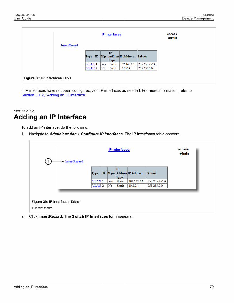
RUGGEDCOM ROSUser Guide
Chapter 3Device Management
Adding an IP Interface 79
Figure 38: IP Interfaces Table
If IP interfaces have not been configured, add IP interfaces as needed. For more information, refer toSection 3.7.2, “Adding an IP Interface”.
Section 3.7.2
Adding an IP InterfaceTo add an IP interface, do the following:
1. Navigate to Administration » Configure IP Interfaces. The IP Interfaces table appears.
1
Figure 39: IP Interfaces Table
1. InsertRecord
2. Click InsertRecord. The Switch IP Interfaces form appears.

Chapter 3Device Management
RUGGEDCOM ROSUser Guide
80 Adding an IP Interface
7
8
1
2
3
4
5
6
9
Figure 40: IP Interfaces Form
1. Type Options 2. ID Box 3. Mgmt Options 4. IP Address Type Box 5. IP Address Box 6. Subnet Box 7. Apply Button 8. Delete Button 9. Reload Button
3. Configure the following parameter(s) as required:
NOTEThe IP address and mask configured for the management VLAN are not changed when resettingall configuration parameters to defaults and will be assigned a default VLAN ID of 1. Changes tothe IP address take effect immediately. All IP connections in place at the time of an IP addresschange will be lost.
Parameter Description
Type Synopsis: { VLAN }Default: VLAN
Specifies the type of the interface for which this IP interface is created.
ID Synopsis: 1 to 4094Default: 1Specifies the ID of the interface for which this IP interface is created. If the interface typeis VLAN, this represents the VLAN ID.
Mgmt Synopsis: { No, Yes }Default: No
Specifies whether the IP interface is the device management interface.
IP Address Type Synopsis: { Static, Dynamic, DHCP, BOOTP }Default: Static
Specifies whether the IP address is static or is dynamically assigned via DHCP orBOOTP>. The Dynamic option automatically switches between BOOTP and DHCP untilit receives a response from the relevant server. The Static option must be used for non-management interfaces.
IP Address Synopsis: ###.###.###.### where ### ranges from 0 to 255Default: 192.168.0.1
Specifies the IP address of this device. An IP address is a 32-bit number that is notatedby using four numbers from 0 through 255, separated by periods. Only a unicast IPaddress is allowed, which ranges from 1.0.0.0 to 233.255.255.255.
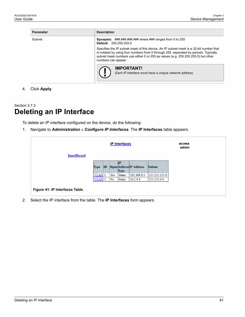
RUGGEDCOM ROSUser Guide
Chapter 3Device Management
Deleting an IP Interface 81
Parameter Description
Subnet Synopsis: ###.###.###.### where ### ranges from 0 to 255Default: 255.255.255.0
Specifies the IP subnet mask of this device. An IP subnet mask is a 32-bit number thatis notated by using four numbers from 0 through 255, separated by periods. Typically,subnet mask numbers use either 0 or 255 as values (e.g. 255.255.255.0) but othernumbers can appear.
IMPORTANT!Each IP interface must have a unique network address.
4. Click Apply.
Section 3.7.3
Deleting an IP InterfaceTo delete an IP interface configured on the device, do the following:
1. Navigate to Administration » Configure IP Interfaces. The IP Interfaces table appears.
Figure 41: IP Interfaces Table
2. Select the IP interface from the table. The IP Interfaces form appears.

Chapter 3Device Management
RUGGEDCOM ROSUser Guide
82 Managing IP Gateways
7
8
1
2
3
4
5
6
9
Figure 42: IP Interfaces Form
1. IP Address Type Box 2. IP Address Box 3. Subnet Box 4. Apply Button 5. Delete Button 6. Reload Button
3. Click Delete.
Section 3.8
Managing IP GatewaysROS allows up to ten IP gateways to be configured. When both the Destination and Subnet parameters areblank, the gateway is considered to be a default gateway.
NOTEThe default gateway configuration will not be changed when resetting all configuration parameters totheir factory defaults.
The following sections describe how to set up and manage IP gateways:
• Section 3.8.1, “Viewing a List of IP Gateways”
• Section 3.8.2, “Adding an IP Gateway”
• Section 3.8.3, “Deleting an IP Gateway”
Section 3.8.1
Viewing a List of IP GatewaysTo view a list of IP gateways configured on the device, navigate to Administration » Configure IP Gateways.The IP Gateways table appears.

RUGGEDCOM ROSUser Guide
Chapter 3Device Management
Adding an IP Gateway 83
Figure 43: IP Gateways Table
If IP gateways have not been configured, add IP gateways as needed. For more information, refer toSection 3.8.2, “Adding an IP Gateway”.
Section 3.8.2
Adding an IP GatewayTo add an IP gateway, do the following:
1. Navigate to Administration » Configure IP Gateways. The IP Gateways table appears.
1
Figure 44: IP Gateways Table
1. InsertRecord
2. Click InsertRecord. The IP Gateways form appears.

Chapter 3Device Management
RUGGEDCOM ROSUser Guide
84 Deleting an IP Gateway
64
5
2
1
3
Figure 45: IP Gateways
1. Destination Box 2. Subnet Box 3. Gateway Box 4. Apply Button 5. Delete Button 6. Reload Button
3. Configure the following parameter(s) as required:
Parameter Description
Destination Synopsis: ###.###.###.### where ### ranges from 0 to 255
Specifies the IP address of destination network or host. For default gateway, both thedestination and subnet are 0.
Subnet Synopsis: ###.###.###.### where ### ranges from 0 to 255
Specifies the destination IP subnet mask. For default gateway, both the destination andsubnet are 0.
Gateway Synopsis: ###.###.###.### where ### ranges from 0 to 255
Specifies the gateway to be used to reach the destination.
4. Click Apply.
Section 3.8.3
Deleting an IP GatewayTo delete an IP gateway configured on the device, do the following:
1. Navigate to Administration » Configure IP Gateways. The IP Gateways table appears.
Figure 46: IP Gateways Table
2. Select the IP gateway from the table. The IP Gateways form appears.

RUGGEDCOM ROSUser Guide
Chapter 3Device Management
Configuring IP Services 85
64
5
2
1
3
Figure 47: IP Gateways Form
1. Destination Box 2. Subnet Box 3. Gateway Box 4. Apply Button 5. Delete Button 6. Reload Button
3. Click Delete.
Section 3.9
Configuring IP ServicesTo configure the IP services provided by the device, do the following:
1. Navigate to Administration » Configure IP Services. The IP Services form appears.
8 9
7
6
5
4
3
2
1
Figure 48: IP Services Form
1. Inactivity Timeout Box 2. Telnet Sessions Allowed Box 3. Web Server Users Allowed Box 4. TFTP Server Box 5. ModbusAddress Box 6. SSH Sessions Allowed Box 7. RSH Server Box 8. Apply Button 9. Reload Button
2. Configure the following parameter(s) as required:
Parameter Description
Inactivity Timeout Synopsis: 1 to 60 or { Disabled }
Chapter 3Device Management
RUGGEDCOM ROSUser Guide
86 Managing Remote Monitoring
Parameter Description
Default: 5 min
Specifies when the console will timeout and display the login screen if there is no useractivity. A value of zero disables timeouts. For Web Server users maximum timeoutvalue is limited to 30 minutes.
Telnet Sessions Allowed Synopsis: 0 to 4Default: 0 (controlled version) or 4 (non-controlled version)
Limits the number of Telnet sessions. A value of zero prevents any Telnet access.
Web Server Users Allowed Synopsis: 1 to 4Default: 4Limits the number of simultaneous web server users.
TFTP Server Synopsis: { Disabled, Get Only, Enabled }Default: Disabled
As TFTP is a very insecure protocol, this parameter allows user to limit or disable TFTPServer access..
DISABLED - disables read and write access to TFTP Server
GET ONLY - only allows reading of files via TFTP Server
ENABLED - allows reading and writing of files via TFTP Server
ModBus Address Synopsis: 1 to 255 or { Disabled }Default: Disabled
Determines the Modbus address to be used for Management through Modbus.
SSH Sessions Allowed (ControlledVersion Only)
Synopsis: 1 to 4Default: 4Limits the number of SSH sessions.
RSH Server Synopsis: { Disabled, Enabled }Default: Disabled (controlled version) or Enabled (non-controlled version)
Disables/enables Remote Shell access.
3. Click Apply.
Section 3.10
Managing Remote MonitoringRemote Monitoring (RMON) is used to collect and view historical statistics related to the performance andoperation of Ethernet ports. It can also record a log entry and/or generate an SNMP trap when the rate ofoccurrence of a specified event is exceeded.
The following sections describe how to configure and manage Remote Monitoring:
• Section 3.10.1, “Managing RMON History Controls”
• Section 3.10.2, “Managing RMON Alarms”
• Section 3.10.3, “Managing RMON Events”
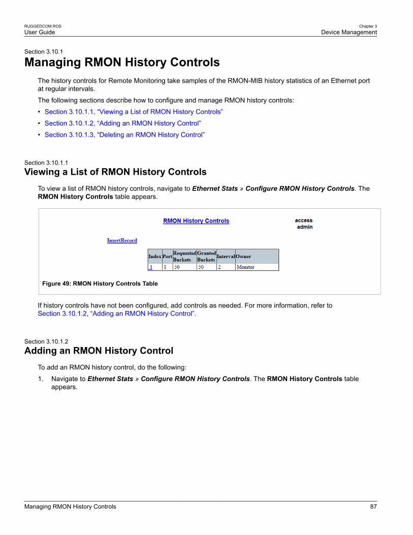
RUGGEDCOM ROSUser Guide
Chapter 3Device Management
Managing RMON History Controls 87
Section 3.10.1
Managing RMON History ControlsThe history controls for Remote Monitoring take samples of the RMON-MIB history statistics of an Ethernet portat regular intervals.
The following sections describe how to configure and manage RMON history controls:
• Section 3.10.1.1, “Viewing a List of RMON History Controls”
• Section 3.10.1.2, “Adding an RMON History Control”
• Section 3.10.1.3, “Deleting an RMON History Control”
Section 3.10.1.1
Viewing a List of RMON History ControlsTo view a list of RMON history controls, navigate to Ethernet Stats » Configure RMON History Controls. TheRMON History Controls table appears.
Figure 49: RMON History Controls Table
If history controls have not been configured, add controls as needed. For more information, refer toSection 3.10.1.2, “Adding an RMON History Control”.
Section 3.10.1.2
Adding an RMON History ControlTo add an RMON history control, do the following:
1. Navigate to Ethernet Stats » Configure RMON History Controls. The RMON History Controls tableappears.

Chapter 3Device Management
RUGGEDCOM ROSUser Guide
88 Adding an RMON History Control
1
Figure 50: RMON History Controls Table
1. InsertRecord
2. Click InsertRecord. The RMON History Controls form appears.
107
8
1
2
3
4
5
6
9
Figure 51: RMON History Controls Form
1. Index Box 2. Port Box 3. Requested Buckets Box 4. Granted Buckets Box 5. Interval Box 6. Owner Box 7. ApplyButton 8. Delete Button 9. Reload Button
3. Configure the following parameter(s) as required:
Parameter Description
Index Synopsis: 1 to 65535Default: 1The index of this RMON History Contol record.
Port Synopsis: 1 to maximum port numberDefault: 1The port number as seen on the front plate silkscreen of the switch.
Requested Buckets Synopsis: 1 to 4000Default: 50
The maximum number of buckets requested for this RMON collection history group ofstatistics. The range is 1 to 4000. The default is 50.
Granted Buckets Synopsis: 0 to 65535

RUGGEDCOM ROSUser Guide
Chapter 3Device Management
Deleting an RMON History Control 89
Parameter Description
The number of buckets granted for this RMON collection history. This field is noteditable.
Interval Synopsis: 1 to 3600Default: 1800
The number of seconds in over which the data is sampled for each bucket. The range is1 to 3600. The default is 1800.
Owner Synopsis: Any 127 charactersDefault: Monitor
The owner of this record. It is suggested to start this string withword 'monitor'.
4. Click Apply.
Section 3.10.1.3
Deleting an RMON History ControlTo delete an RMON history control, do the following:
1. Navigate to Ethernet Stats » Configure RMON History Controls. The RMON History Controls tableappears.
Figure 52: RMON History Controls Table
2. Select the history control from the table. The RMON History Controls form appears.

Chapter 3Device Management
RUGGEDCOM ROSUser Guide
90 Managing RMON Alarms
107
8
1
2
3
4
5
6
9
Figure 53: RMON History Controls Form
1. Index Box 2. Port Box 3. Requested Buckets Box 4. Granted Buckets Box 5. Interval Box 6. Owner Box 7. ApplyButton 8. Delete Button 9. Reload Button
3. Click Delete.
Section 3.10.2
Managing RMON AlarmsWhen Remote Monitoring (RMON) alarms are configured, ROS examines the state of a specific statisticalvariable.
Remote Monitoring (RMON) alarms define upper and lower thresholds for legal values of specific statisticalvariables in a given interval. This allows ROS to detect events as they occur more quickly than a specifiedmaximum rate or less quckly than a minimum rate.
When the rate of change for a statistics value exceeds its limits, an internal INFO alarm is always generated. Forinformation about viewing alarms, refer to Section 4.4.2, “Viewing and Clearing Latched Alarms”.
Additionally, a statistic threshold crossing can result in further activity. An RMON alarm can be configured to pointto a particular RMON event, which can generate an SNMP trap, an entry in the event log, or both. The RMONevent can also direct alarms towards different users defined for SNMP.
The alarm can point to a different event for each of the thresholds. Therefore, combinations such as trap on risingthreshold or trap on rising threshold, log and trap on falling threshold are possible.
Each RMON alarm may be configured such that its first instance occurs only for rising, falling, or all thresholdsthat exceed their limits.
The ability to configure upper and lower thresholds on the value of a measured statistic provides for the ability toadd hysteresis to the alarm generation process.
If the value of the measured statistic over time is compared to a single threshold, alarms will be generated eachtime the statistic crosses the threshold. If the statistic’s value fluctuates around the threshold, an alarm can begenerated every measurement period. Programming different upper and lower thresholds eliminates spuriousalarms. The statistic value must travel between the thresholds before alarms can be generated. The followingillustrates the very different patterns of alarm generation resulting from a statistic sample and the same samplewith hysteresis applied.

RUGGEDCOM ROSUser Guide
Chapter 3Device Management
Viewing a List of RMON Alarms 91
Figure 54: The Alarm Process
There are two methods to evaluate a statistic in order to determine when to generate an event: delta andabsolute.
For most statistics, such as line errors, it is appropriate to generate an alarm when a rate is exceeded. Thealarm defaults to the delta measurement method, which examines changes in a statistic at the end of eachmeasurement period.
It may be desirable to alarm when the total, or absolute, number of events crosses a threshold. In this case, setthe measurement period type to absolute.
The following sections describe how to configure and manage RMON alarms:
• Section 3.10.2.1, “Viewing a List of RMON Alarms”
• Section 3.10.2.2, “Adding an RMON Alarm”
• Section 3.10.2.3, “Deleting an RMON Alarm”
Section 3.10.2.1
Viewing a List of RMON AlarmsTo view a list of RMON alarms, navigate to Ethernet Stats » Configure RMON Alarms. The RMON Alarmstable appears.
Figure 55: RMON Alarms Table
If alarms have not been configured, add alarms as needed. For more information, refer to Section 3.10.2.2,“Adding an RMON Alarm”.

Chapter 3Device Management
RUGGEDCOM ROSUser Guide
92 Adding an RMON Alarm
Section 3.10.2.2
Adding an RMON AlarmTo add an RMON alarm, do the following:
1. Navigate to Ethernet Stats » Configure RMON Alarms. The RMON Alarms table appears.
1
Figure 56: RMON Alarms Table
1. InsertRecord
2. Click InsertRecord. The RMON Alarms form appears.
1412
13
1
2
3
4
5
6
7
8
9
10
11
Figure 57: RMON Alarms Form
1. Index Box 2. Variable Box 3. Rising Thr Box 4. Falling Thr Box 5. Value Box 6. Type Options 7. Interval Box 8. StartupAlarm List 9. Rising Event Box 10. Falling Event Box 11. Owner Box 12. Apply Button 13. Delete Button 14. Reload Button
3. Configure the following parameter(s) as required:

RUGGEDCOM ROSUser Guide
Chapter 3Device Management
Adding an RMON Alarm 93
Parameter Description
Index Synopsis: 1 to 65535Default: 1The index of this RMON Alarm record.
Variable Synopsis: SNMP Object Identifier - up to 39 characters
The SNMP object identifier (OID) of the particular variable to be sampled. Only variablesthat resolve to an ASN.1 primitive type INTEGER (INTEGER, Integer32,Counter32,Counter64, Gauge, or TimeTicks) may be sampled. A list of objects can be printed usingshell command 'rmon'. The OID format: objectName.index1.index2... where index formatdepends on index object type.
Rising Thr Synopsis: -2147483647 to 2147483647Default: 0A threshold for the sampled variable. When the current sampled variable value isgreater than or equal to this threshold, and the value at the last sampling interval wasless than this threshold, a single event will be generated. A single event will also begenerated if the first sample after this record is created is greater than or equal tothis threshold and the associated startup alarm ils equal to 'rising'.After rising alarm isgenerated, another such event will not be generated until the sampled value falls belowthis threshold and reaches the value of FallingThreshold.
Falling Thr Synopsis: -2147483647 to 2147483647Default: 0A threshold for the sampled variable. When the current sampled variable value isless than or equal to this threshold, and the value at the last sampling interval wasgreater than this threshold, a single event will be generated. A single event will alsobe generated if the first sample after this record is created is less than or equal to thisthreshold and the associated startup alarm ils equal to 'falling'.After falling alarm isgenerated, another such event will not be generated until the sampled value rises abovethis threshold and reaches the value of RisingThreshold.
Value Synopsis: -2147483647 to 2147483647
The value of monitoring object during the last sampling period. The presentation ofvalue depends of sample type ('absolute' or 'delta').
Type Synopsis: { absolute, delta }Default: delta
The method of sampling the selected variable and calculating the value to be comparedagainst the thresholds. The value of sample type can be 'absolute' or 'delta'.
Interval Synopsis: 0 to 2147483647Default: 60
The number of seconds in over which the data is sampled and compared with the risingand falling thresholds.
Startup Alarm Synopsis: { rising, falling, risingOrFalling }Default: risingOrFalling
The alarm that may be sent when this record is first created if condition for raising alarmis met. The value of startup alarm can be 'rising', 'falling' or 'risingOrFalling'.
Rising Event Synopsis: 0 to 65535Default: 0The index of the event that is used when a falling threshold is crossed. If there is nocorresponding entryl in the Event Table, then no association exists. In particular, if thisvalue is zero, no associated event will be generated.
Falling Event Synopsis: 0 to 65535Default: 0

Chapter 3Device Management
RUGGEDCOM ROSUser Guide
94 Deleting an RMON Alarm
Parameter Description
The index of the event that is used when a rising threshold is crossed. If there is nocorresponding entryl in the Event Table, then no association exists. In particular, if thisvalue is zero, no associated event will be generated.
Owner Synopsis: Any 127 charactersDefault: Monitor
The owner of this record. It is suggested to start this string withword 'monitor'.
4. Click Apply.
Section 3.10.2.3
Deleting an RMON AlarmTo delete an RMON alarm, do the following:
1. Navigate to Ethernet Stats » Configure RMON Alarms. The RMON Alarms table appears.
Figure 58: RMON Alarms Table
2. Select the alarm from the table. The RMON Alarms form appears.
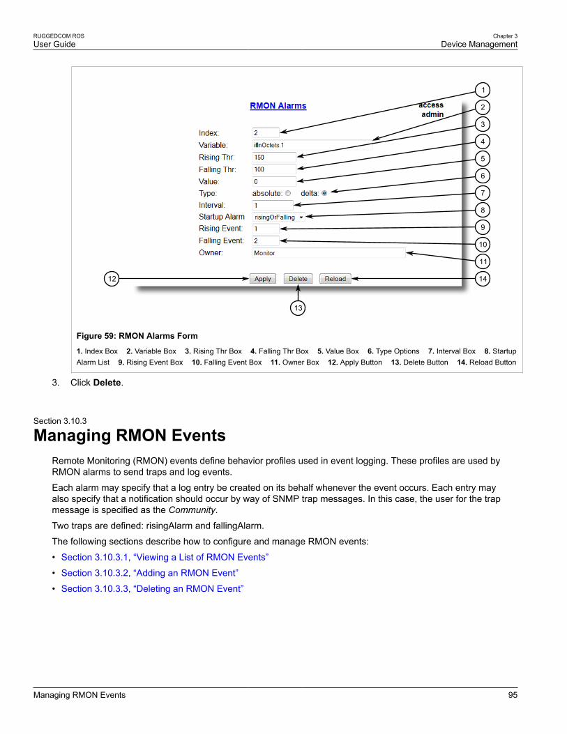
RUGGEDCOM ROSUser Guide
Chapter 3Device Management
Managing RMON Events 95
1412
13
1
2
3
4
5
6
7
8
9
10
11
Figure 59: RMON Alarms Form
1. Index Box 2. Variable Box 3. Rising Thr Box 4. Falling Thr Box 5. Value Box 6. Type Options 7. Interval Box 8. StartupAlarm List 9. Rising Event Box 10. Falling Event Box 11. Owner Box 12. Apply Button 13. Delete Button 14. Reload Button
3. Click Delete.
Section 3.10.3
Managing RMON EventsRemote Monitoring (RMON) events define behavior profiles used in event logging. These profiles are used byRMON alarms to send traps and log events.
Each alarm may specify that a log entry be created on its behalf whenever the event occurs. Each entry mayalso specify that a notification should occur by way of SNMP trap messages. In this case, the user for the trapmessage is specified as the Community.
Two traps are defined: risingAlarm and fallingAlarm.
The following sections describe how to configure and manage RMON events:
• Section 3.10.3.1, “Viewing a List of RMON Events”
• Section 3.10.3.2, “Adding an RMON Event”
• Section 3.10.3.3, “Deleting an RMON Event”

Chapter 3Device Management
RUGGEDCOM ROSUser Guide
96 Viewing a List of RMON Events
Section 3.10.3.1
Viewing a List of RMON EventsTo view a list of RMON events, navigate to Ethernet Stats » Configure RMON Events. The RMON Events tableappears.
Figure 60: RMON Events Table
If events have not been configured, add events as needed. For more information, refer to Section 3.10.3.2,“Adding an RMON Event”.
Section 3.10.3.2
Adding an RMON EventTo add an RMON alarm, do the following:
1. Navigate to Ethernet Stats » Configure RMON Events. The RMON Events table appears.
1
Figure 61: RMON Events Table
1. InsertRecord
2. Click InsertRecord. The RMON Events form appears.
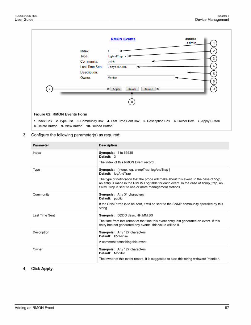
RUGGEDCOM ROSUser Guide
Chapter 3Device Management
Adding an RMON Event 97
97
8
1
2
3
4
5
6
Figure 62: RMON Events Form
1. Index Box 2. Type List 3. Community Box 4. Last Time Sent Box 5. Description Box 6. Owner Box 7. Apply Button 8. Delete Button 9. View Button 10. Reload Button
3. Configure the following parameter(s) as required:
Parameter Description
Index Synopsis: 1 to 65535Default: 3The index of this RMON Event record.
Type Synopsis: { none, log, snmpTrap, logAndTrap }Default: logAndTrap
The type of notification that the probe will make about this event. In the case of 'log',an entry is made in the RMON Log table for each event. In the case of snmp_trap, anSNMP trap is sent to one or more management stations.
Community Synopsis: Any 31 charactersDefault: public
If the SNMP trap is to be sent, it will be sent to the SNMP community specified by thisstring.
Last Time Sent Synopsis: DDDD days, HH:MM:SS
The time from last reboot at the time this event entry last generated an event. If thisentry has not generated any events, this value will be 0.
Description Synopsis: Any 127 charactersDefault: EV2-Rise
A comment describing this event.
Owner Synopsis: Any 127 charactersDefault: Monitor
The owner of this event record. It is suggested to start this string withword 'monitor'.
4. Click Apply.

Chapter 3Device Management
RUGGEDCOM ROSUser Guide
98 Deleting an RMON Event
Section 3.10.3.3
Deleting an RMON EventTo delete an RMON event, do the following:
1. Navigate to Ethernet Stats » Configure RMON Events. The RMON Events table appears.
Figure 63: RMON Events Table
2. Select the event from the table. The RMON Events form appears.
97
8
1
2
3
4
5
6
Figure 64: RMON Events Form
1. Index Box 2. Type List 3. Community Box 4. Last Time Sent Box 5. Description Box 6. Owner Box 7. Apply Button 8. Delete Button 9. View Button 10. Reload Button
3. Click Delete.
Section 3.11
Upgrading/Downgrading FirmwareThe following sections describe how to upgrade and downgrade the firmware:
• Section 3.11.1, “Upgrading Firmware”
• Section 3.11.2, “Downgrading Firmware”

RUGGEDCOM ROSUser Guide
Chapter 3Device Management
Upgrading Firmware 99
Section 3.11.1
Upgrading FirmwareUpgrading ROS firmware, including the main, bootloader and FPGA firmware, may be necessary totake advantage of new features or bug fixes. Binary firmware images are available from Siemens . Visitwww.siemens.com/ruggedcom to determine which versions/updates are available or contact Siemens CustomerSupport.
Binary firmware images transferred to the device are stored in non-volatile Flash memory and require a devicereset in order to take effect.
IMPORTANT!Non-Controlled (NC) versions of ROS can not be upgraded to Controlled firmware versions. However,Controlled firmware versions can be upgraded to an NC firmware version.
NOTEThe IP address set for the device will not be changed following a firmware upgrade.
To upgrade the ROS firmware, do the following:
1. Upload a different version of the binary firmware image to the device. For more information, refer toSection 3.4, “Uploading/Downloading Files”.
2. Reset the device to complete the installation. For more information, refer to Section 3.12, “Resetting theDevice”.
3. Access the CLI shell and verify the new software version has been installed by typing version. Thecurrently installed versions of the main and boot firmware are displayed.
>versionCurrent ROS-CF52 Boot Software v2.20.0 (Jan 29 2013 13:25)Current ROS-CF52 Main Software v4.0 (Feb 2 2013 09:33)
Section 3.11.2
Downgrading FirmwareDowngrading the ROS firmware is generally not recommended, as it may have unpredictable effects. However, ifa downgrade is required, do the following:
IMPORTANT!Before downgrading the firmware, make sure the hardware and FPGA code types installed in thedevice are supported by the older firmware version. Refer to the Release Notes for the older firmwareversion to confirm.
IMPORTANT!Non-Controlled (NC) versions of ROS can not be downgraded to Controlled firmware versions.However, Controlled firmware versions can be downgraded to an NC firmware version.
CAUTION!Do not downgrade the ROS boot version.
1. Disconnect the device from the network.

Chapter 3Device Management
RUGGEDCOM ROSUser Guide
100 Resetting the Device
2. Log in to the device as an admin user. For more information, refer to Section 2.2, “Logging In”.
3. Make a local copy of the current configuration file. For more information, refer to Section 3.4, “Uploading/Downloading Files”.
IMPORTANT!Never downgrade the ROS software version beyond ROS v4.1 when encryption is enabled. Makesure the device has been restored to factory defaults before downgrading.
4. Restore the device to its factory defaults. For more information, refer to Section 3.3, “Restoring FactoryDefaults”.
5. Upload and apply the older firmware version and its associated FPGA files using the same methods used toinstall newer firmware versions. For more information , refer to Section 3.11.1, “Upgrading Firmware”.
6. Press Ctrl-S to access the CLI.
7. Clear all logs by typing:
clearlogs
8. Clear all alarms by typing:
clearalarms
IMPORTANT!After downgrading the firmware and FPGA files, be aware that some settings from the previousconfiguration may be lost or reverted back to the factory defaults (including user’s passwords ifdowngrading from a security related version), as those particular tables or fields may not exist inthe older firmware version. Because of this, the unit must be configured after the downgrade.
9. Configure the device as required.
Section 3.12
Resetting the DeviceTo reset the device, do the following:
1. Navigate to Diagnostics » Reset Device. The Reset Device form appears.
1
Figure 65: Reset Device Form
1. Confirm Button
2. Click Confirm.

RUGGEDCOM ROSUser Guide
Chapter 3Device Management
Decommissioning the Device 101
Section 3.13
Decommissioning the DeviceBefore taking the device out of service, either permanently or for maintenance by a third-party, make sure thedevice has been fully decommissioned. This includes removing any sensitive, proprietary information.
To decommission the device, do the following:
1. Disconnect all network cables from the device.
2. Connect to the device via the RS232 serial console port. For more information, refer to Section 2.1.1,“Connecting Directly”.
3. Restore all factory default settings for the device. For more information, refer to Section 3.3, “RestoringFactory Defaults”.
4. Access the CLI. For more information, refer to Section 2.6, “Using the Command Line Interface”.
5. Upload a blank version of the banner.txt file to the device to replace the existing file. For more informationabout uploading a file, refer to Section 3.4, “Uploading/Downloading Files”.
6. Confirm the upload was successful by typing:
type banner.txt
7. Clear the system and crash logs by typing:
clearlog
8. Generate a random SSL certificate by typing:
sslkeygen
This may take several minutes to complete. To verify the certificate has been generated, type:
type syslog.txt
When the phraseGenerated ssl.crt was saved
appears in the log, the SSL certificate has been generated.
9. Generate random SSH keys by typing:
sshkeygen
This may take several minutes to complete. To verify the keys have been generated, type:
type syslog.txt
When the phraseGenerated ssh.keys was saved
appears in the log, the SSH keys have been generated.
10. De-fragment and erase all free flash memory by typing:
flashfile defrag
This may take several minutes to complete.

RUGGEDCOM ROSUser Guide
Chapter 3Device Management
Decommissioning the Device 102

RUGGEDCOM ROSUser Guide
Chapter 4System Administration
Configuring the System Information 103
System AdministrationThis chapter describes how to perform various administrative tasks related to device identification, userpermissions, alarm configuration, certificates and keys, and more. It describes the following tasks:
• Section 4.1, “Configuring the System Information”
• Section 4.2, “Customizing the Login Screen”
• Section 4.3, “Configuring Passwords”
• Section 4.4, “Managing Alarms”
• Section 4.5, “Managing the Configuration File”
• Section 4.6, “Managing an Authentication Server”
Section 4.1
Configuring the System InformationTo configure basic information that can be used to identify the device, its location, and/or its owner, do thefollowing:
1. Navigate to Administration » Configure System Identification. The System Identification form appears.
54
3
2
1
Figure 66: System Identification Form
1. System Name Box 2. Location Box 3. Contact Box 4. Apply Button 5. Reload Button
2. Configure the following parameter(s) as required:
Parameter Description
System Name Synopsis: Any 24 characters
The system name is displayed in all ROS menu screens. This can make it easier toidentify the switches within your network provided that all switches are given a uniquename.
Location Synopsis: Any 49 characters
The location can be used to indicate the physical location of the switch. It is displayed inthe login screen as another means to ensure you are dealing with the desired switch.
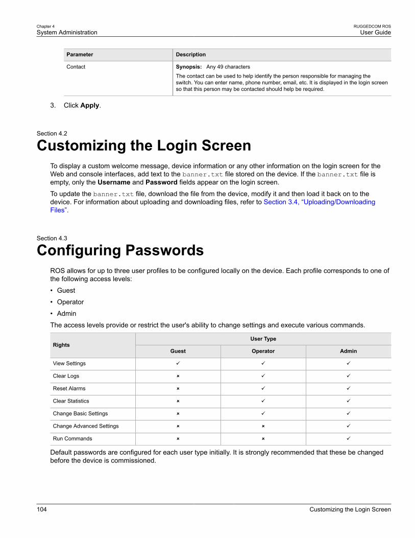
Chapter 4System Administration
RUGGEDCOM ROSUser Guide
104 Customizing the Login Screen
Parameter Description
Contact Synopsis: Any 49 characters
The contact can be used to help identify the person responsible for managing theswitch. You can enter name, phone number, email, etc. It is displayed in the login screenso that this person may be contacted should help be required.
3. Click Apply.
Section 4.2
Customizing the Login ScreenTo display a custom welcome message, device information or any other information on the login screen for theWeb and console interfaces, add text to the banner.txt file stored on the device. If the banner.txt file isempty, only the Username and Password fields appear on the login screen.
To update the banner.txt file, download the file from the device, modify it and then load it back on to thedevice. For information about uploading and downloading files, refer to Section 3.4, “Uploading/DownloadingFiles”.
Section 4.3
Configuring PasswordsROS allows for up to three user profiles to be configured locally on the device. Each profile corresponds to one ofthe following access levels:
• Guest
• Operator
• Admin
The access levels provide or restrict the user's ability to change settings and execute various commands.
User TypeRights
Guest Operator Admin
View Settings ü ü ü
Clear Logs û ü ü
Reset Alarms û ü ü
Clear Statistics û ü ü
Change Basic Settings û ü ü
Change Advanced Settings û û ü
Run Commands û û ü
Default passwords are configured for each user type initially. It is strongly recommended that these be changedbefore the device is commissioned.

RUGGEDCOM ROSUser Guide
Chapter 4System Administration
Configuring Passwords 105
NOTEUsers can also be verified through a RADIUS or TACACS+ server. When enabled for authenticationand authorization, the RADIUS or TACACS+ server will be used in the absence of any local settings.For more information about configuring a RADIUS or TACACS+ server, refer to Section 4.6, “Managingan Authentication Server”.
CAUTION!To prevent unauthorized access to the device, make sure to change the default passwords for eachprofile before commissioning the device.
To configure passwords for one or more of the user profiles, do the following:
1. Navigate to Administration » Configure Passwords. The Configure Passwords form appears.
9
11
8
7
6
5
4
3
2
11
10
12
Figure 67: Configure Passwords Form
1. Auth Type Box 2. Guest Username Box 3. Guest Password Box 4. Confirm Guest Password Box 5. Operator UsernameBox 6. Operator Password Box 7. Confirm Operator Password Box 8. Admin Username Box 9. Admin Password Box 10. Confirm Admin Password Box 11. Apply Button 12. Reload Button
NOTEROS requires that all user passwords meet strict guidelines to prevent the use of weak passwords.When creating a new password, make sure it adheres to the following rules:
• Must not be less than 8 characters in length.
• Must not include the username or any 4 continous characters found in the username. Forexample, if the username is Subnet25, the password may not be subnet25admin, subnetadminor net25admin. However, net-25admin or Sub25admin is permitted.
• Must have at least one alphabetic character and one number. Special characters are permitted.
• Must not have more than 3 continuously incrementing or decrementing numbers. For example,Sub123 and Sub19826 are permitted, but Sub12345 is not.

Chapter 4System Administration
RUGGEDCOM ROSUser Guide
106 Configuring Passwords
An alarm will generate if a weak password is configured. The weak password alarm can bedisabled by the user. For more information about disabling alarms, refer to Section 4.4, “ManagingAlarms”.
2. Configure the following parameter(s) as required:
Parameter Description
Auth Type Synopsis: { Local, RADIUS, TACACS+, RADIUSorLocal, TACACS+orLocal }Default: Local
Password can be authenticated using localy configured values, or remote RADIUS orTACACS+ server. Setting value to any of combinations that involve RADIUS or TACACS+ require Security Server Table to be configured.
Settings:
• Local - Authentication from the local Password Table.• RADIUS - Authentication using a RADIUS server.• TACACS+ - Authentication using a TACACS+ server.• RADIUSOrLocal - Authentication using RADIUS. If the server cannot be reached,
authenticate from the local Password Table.• TACACS+OrLocal - Authentication using TACACS+. If the server cannot be reached,
authenticate from the local Password Table
NOTEFor console access, local credentials will always be checked firstregardless of the device configuration. If server authentication is required,requests to the server will be sent only if local authentication fails.
Guest Username Synopsis: Any 15 charactersDefault: guest
Related password is in field Guest Password; view only, cannot change settings or runany commands.
Guest Password Synopsis: 15 character ASCII string
Related username is in field Guest Username; view only, cannot change settings or runany commands.
Confirm Guest Password Synopsis: 15 character ASCII string
Related username is in field Guest Username; view only, cannot change settings or runany commands.
Operator Username Synopsis: Any 15 charactersDefault: operator
Related password is in field Oper Password; cannot change settings; can reset alarms,statistics, logs, etc.
Operator Password Synopsis: 15 character ASCII string
Related username is in field Oper Username; cannot change settings; can reset alarms,statistics, logs, etc
Confirm Operator Password Synopsis: 15 character ASCII string
Related username is in field Oper Username; cannot change settings; can reset alarms,statistics, logs, etc.
Admin Username Synopsis: Any 15 charactersDefault: admin
Related password is in field Admin Password; full read/write access to all settings andcommands.
Admin Password Synopsis: 15 character ASCII string

RUGGEDCOM ROSUser Guide
Chapter 4System Administration
Managing Alarms 107
Parameter Description
Related username is in field Admin Username; full read/write access to all settings andcommands.
Confirm Admin Password Synopsis: 15 character ASCII string
Related username is in field Admin Username; full read/write access to all settings andcommands.
3. Click Apply.
Section 4.4
Managing AlarmsAlarms indicate the occurrence of events of either importance or interest that are logged by the device.
There are two types of alarms:
• Active alarms signify states of operation that are not in accordance with normal operation. Examples includelinks that should be up, but are not, or error rates that repeatedly exceed a certain threshold. These alarms arecontinuously active and are only cleared when the problem that triggered the alarms is resolved.
• Passive alarms are a record of abnormal conditions that occurred in the past and do not affect th currentoperation state of the device. Examples include authentication failures, Remote Network MONitoring (RMON)MIB generated alarms, or error states that temporarily exceeded a certain threshold . These alarms can becleared from the list of alarms.
NOTEFor more information about RMON alarms, refer to Section 3.10.2, “Managing RMON Alarms”.
When either type of alarm occurs, a message appears in the top right corner of the user interface. If more thanone alarm has occurred, the message will indicate the number of alarms. Active alarms also trip the CriticalFailure Relay LED on the device. The message and the LED will remain active until the alarm is cleared.
NOTEAlarms are volatile in nature. All alarms (active and passive) are cleared at startup.
The following sections describe how to set up and manage alarms:
• Section 4.4.1, “Viewing a List of Pre-Configured Alarms”
• Section 4.4.2, “Viewing and Clearing Latched Alarms”
• Section 4.4.3, “Configuring an Alarm”
• Section 4.4.4, “Authentication Related Security Alarms”
Section 4.4.1
Viewing a List of Pre-Configured AlarmsTo view a list of alarms pre-configured for the device, navigate to Diagnostic » Configure Alarms. The Alarmstable appears.
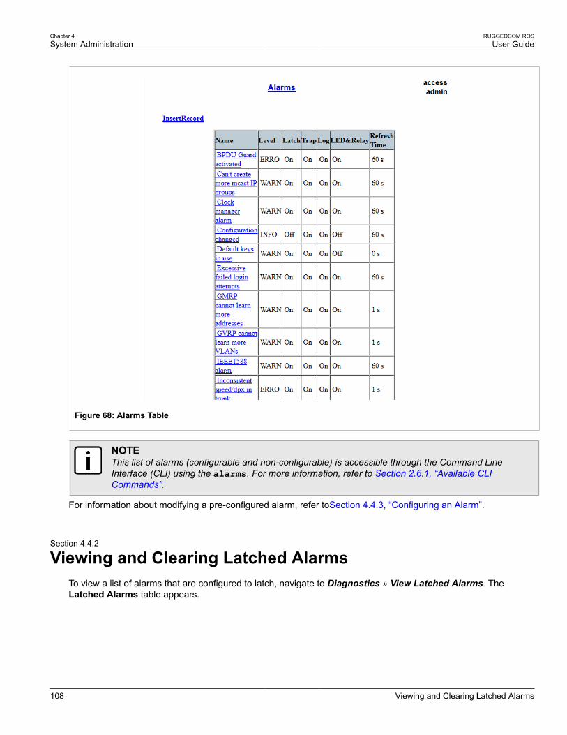
Chapter 4System Administration
RUGGEDCOM ROSUser Guide
108 Viewing and Clearing Latched Alarms
Figure 68: Alarms Table
NOTEThis list of alarms (configurable and non-configurable) is accessible through the Command LineInterface (CLI) using the alarms. For more information, refer to Section 2.6.1, “Available CLICommands”.
For information about modifying a pre-configured alarm, refer toSection 4.4.3, “Configuring an Alarm”.
Section 4.4.2
Viewing and Clearing Latched AlarmsTo view a list of alarms that are configured to latch, navigate to Diagnostics » View Latched Alarms. TheLatched Alarms table appears.

RUGGEDCOM ROSUser Guide
Chapter 4System Administration
Configuring an Alarm 109
Figure 69: Latched Alarms Table
To clear the passive alarms from the list, do the following:
1. Navigate to Diagnostics » Clear Latched Alarms. The Clear Latched Alarms form appears.
1
Figure 70: Clear Latched Alarms Form
1. Confirm Button
2. Click Confirm.
Section 4.4.3
Configuring an AlarmWhile all alarms are pre-configured on the device, some alarms can be modified to suit the application. Thisincludes enabling/disabling certain features and changing the refresh time.
To configuring an alarm, do the following:
IMPORTANT!Critical and Alert level alarms are not configurable and cannot be disabled.
1. Navigate to Diagnostic » Configure Alarms. The Alarms table appears.

Chapter 4System Administration
RUGGEDCOM ROSUser Guide
110 Configuring an Alarm
Figure 71: Alarms Table
2. Select an alarm. The Alarms form appears.
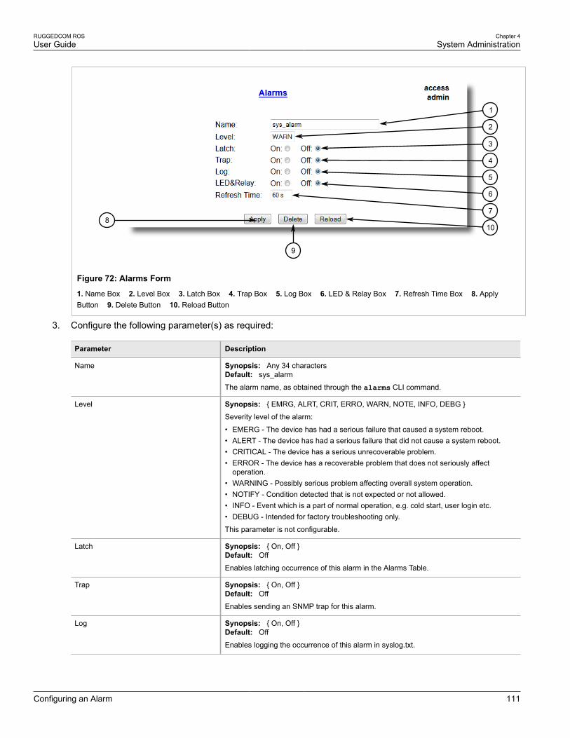
RUGGEDCOM ROSUser Guide
Chapter 4System Administration
Configuring an Alarm 111
108
9
7
6
5
4
3
2
1
Figure 72: Alarms Form
1. Name Box 2. Level Box 3. Latch Box 4. Trap Box 5. Log Box 6. LED & Relay Box 7. Refresh Time Box 8. ApplyButton 9. Delete Button 10. Reload Button
3. Configure the following parameter(s) as required:
Parameter Description
Name Synopsis: Any 34 charactersDefault: sys_alarm
The alarm name, as obtained through the alarms CLI command.
Level Synopsis: { EMRG, ALRT, CRIT, ERRO, WARN, NOTE, INFO, DEBG }
Severity level of the alarm:
• EMERG - The device has had a serious failure that caused a system reboot.• ALERT - The device has had a serious failure that did not cause a system reboot.• CRITICAL - The device has a serious unrecoverable problem.• ERROR - The device has a recoverable problem that does not seriously affect
operation.• WARNING - Possibly serious problem affecting overall system operation.• NOTIFY - Condition detected that is not expected or not allowed.• INFO - Event which is a part of normal operation, e.g. cold start, user login etc.• DEBUG - Intended for factory troubleshooting only.
This parameter is not configurable.
Latch Synopsis: { On, Off }Default: Off
Enables latching occurrence of this alarm in the Alarms Table.
Trap Synopsis: { On, Off }Default: Off
Enables sending an SNMP trap for this alarm.
Log Synopsis: { On, Off }Default: Off
Enables logging the occurrence of this alarm in syslog.txt.

Chapter 4System Administration
RUGGEDCOM ROSUser Guide
112 Authentication Related Security Alarms
Parameter Description
LED & Relay Synopsis: { On, Off }Default: Off
Enables LED and fail-safe relay control for this alarm. If latching is not enabled, this fieldwill remain disabled.
Refresh Time Synopsis: 0 s to 60 sDefault: 60 s
Refreshing time for this alarm.
4. Click Apply.
Section 4.4.4
Authentication Related Security AlarmsThe following describes the authentication-related security messages that can be generated by ROS:
• Section 4.4.4.1, “Security Alarms for Login Authentication”
• Section 4.4.4.2, “Security Messages for Port Authentication”
Section 4.4.4.1
Security Alarms for Login AuthenticationROS provides various logging options related to login authentication. A user can log into a ROS device in threedifferent ways: Console, SSH or Telnet. ROS can log messages in the syslog, send a trap to notify an SNMPmanager, and/or raise an alarm when a successful and unsuccessful login event occurs. In addition, when aweak password is configured on a unit or when the primary authentication server for TACACS+ or RADIUS is notreachable, ROS will raise alarms, send SNMP traps and log messages in the syslog.
The following is a list of log and alarm messages related to user authentication:
• Weak Password Configured
• Login and Logout Information
• Excessive Failed Login Attempts
• RADIUS Server Unreachable
• TACACS Server Unreachable
• TACACS Response Invalid
• SNMP Authentication Failure
NOTEAll alarms and log messages related to login authentication are configurable. For more informationabout configuring alarms, refer to Section 4.4.3, “Configuring an Alarm”.
Weak Password ConfiguredROS generates this alarm and logs a message in the syslog when a weak password is configured in thePasswords table.

RUGGEDCOM ROSUser Guide
Chapter 4System Administration
Security Alarms for Login Authentication 113
Message Name Alarm SNMP Trap Syslog
Weak Password Configured Yes Yes Yes
Default Keys In UseROS generates this alarm and logs a message in the syslog when default keys are in use. For more informationabout default keys, refer to Section 1.8, “Certificate and Key Requirements”.
NOTEFor Non-Controlled (NC) versions of ROS, this alarm is only generated when default SSL keys are inuse.
Message Name Alarm SNMP Trap Syslog
Default Keys In Use Yes Yes Yes
Login and Logout InformationROS generates this alarm and logs a message in the syslog when a successful and unsuccessful login attemptoccurs. A message is also logged in the syslog when a user with a certain privilege level is logged out from thedevice.
Login attempts are logged regardless of how the user accesses the device (i.e. SSH, Web, Console, Telnet orRSH). However, when a user logs out, a message is only logged when the user is accessing the device throughSSH, Telnet or Console.
Message Name Alarm SNMP Trap Syslog
Successful Login Yes Yes Yes
Failed Login Yes Yes Yes
User Logout No No Yes
Excessive Failed Login AttemptsROS generates this alarm and logs a message in the syslog after 10 failed login attempts by a user occur withina span of five minutes. Furthermore, the service the user attempted to access will be blocked for one hour toprevent further attempts.
Message Name Alarm SNMP Trap Syslog
Excessive Failed Login Attempts Yes Yes Yes
RADIUS Server UnreachableROS generates this alarm and logs a message in the syslog when the primary RADIUS server is unreachable.
Message Name Alarm SNMP Trap Syslog
Primary RADIUS ServerUnreachable
Yes Yes Yes
TACACS+ Server UnreachableROS generates this alarm and logs a message in the syslog when the primary TACACS+ server is unreachable.
Message Name Alarm SNMP Trap Syslog
Primary TACACS ServerUnreachable
Yes Yes Yes

Chapter 4System Administration
RUGGEDCOM ROSUser Guide
114 Security Messages for Port Authentication
TACACS+ Response InvalidROS generate this alarm and logs a message in the syslog when the response from the TACACS+ server isreceived with an invalid CRC.
Message Name Alarm SNMP Trap Syslog
TACACS Response Invalid Yes Yes Yes
SNMP Authentication FailureROS generates this alarm, sends an authentication failure trap, and logs a message in the syslog when an SNMPmanager with incorrect credentials communicates with the SNMP agent in ROS.
Message Name Alarm SNMP Trap Syslog
SNMP Authentication Failure Yes Yes Yes
Section 4.4.4.2
Security Messages for Port AuthenticationThe following is the list of log and alarm messages related to port access control in ROS:
• MAC Address Authorization Failure
• Secure Port X Learned MAC Addr on VLAN X
• Port Security Violated
MAC Address Authorization FailureROS generates this alarm and logs a message in the syslog when a host connected to a secure port onthe device is communicating using a source MAC address which has not been authorized by ROS, or thedynamically learned MAC address has exceeded the total number of MAC addresses configured to be learneddynamically on the secured port. This message is only applicable when the port security mode is set to StaticMAC.
Message Name Alarm SNMP Trap Syslog
MAC Address AuthorizationFailure
Yes Yes Yes
Secure Port X Learned MAC Addr on VLAN XROS logs a message in the syslog and sends a configuration change trap when a MAC address is learned ona secure port. Port X indicates the secured port number and VLAN number on that port. This message is notconfigurable in ROS.
Message Name SNMP Trap Syslog
Secure Port X Learned MAC Addr on VLANX
Yes Yes
Port Security ViolatedThis message is only applicable when the security mode for a port is set to "802.1X or 802.1X/MAC-Auth"
ROS this alarm and logs a message in the syslog when the host connected to a secure port tries to communicateusing incorrect login credentials.

RUGGEDCOM ROSUser Guide
Chapter 4System Administration
Managing the Configuration File 115
Message Name Alarm SNMP Trap Syslog
802.1X Port X AuthenticationFailure
Yes Yes Yes
802.1X Port X Authorized Addr.XXX
No No Yes
Section 4.5
Managing the Configuration FileThe device configuration file for ROS is a single CSV (Comma-Separate Value) formatted ASCII text file, namedconfig.csv. It can be downloaded from the device to view, compare against other configuration files, or storefor backup purposes. It can also be overwritten by a complete or partial configuration file uploaded to the device.
To prevent unauthorized access to the contents of the configuration file, the file can be encrypted and given apassword/passphrase key.
The following sections describe how to manage the configuration file:
• Section 4.5.1, “Configuring Data Encryption”
• Section 4.5.2, “Updating the Configuration File”
Section 4.5.1
Configuring Data EncryptionTo encrypt the configuration file and protect it with a password/passphrase, do the following:
NOTEData encryption is not available in Non-Controlled (NC) versions of ROS . When switching betweenControlled and Non-Controlled (NC) versions of ROS , make sure data encryption is disabled.Otherwise, the NC version of ROS will ignore the encrypted configuration file and load the factorydefaults.
NOTEOnly configuration data is encrypted. All comments and table names in the configuration file are savedas clear text.
NOTEWhen sharing a configuration file between devices, make sure both devices have the samepassphrase configured. Otherwise, the configuration file will be rejected.
NOTEEncryption must be disabled before the device is returned to Siemens or the configuration file is sharedwith Customer Support.
IMPORTANT!Never downgrade the ROS software version beyond ROS v4.1 when encryption is enabled. Make surethe device has been restored to factory defaults before downgrading.

Chapter 4System Administration
RUGGEDCOM ROSUser Guide
116 Updating the Configuration File
1. Navigate to Administration » Configure Data Storage. The Data Storage form appears.
54
3
2
1
Figure 73: Data Storage Form
1. Encryption Options 2. Passphrase Box 3. Confirm Passphrase Box 4. Apply Button 5. Reload Button
2. Configure the following parameter(s) as required:
Parameter Description
Encryption Synopsis: { On, Off }
Enable/disable encryption of data in configuration file.
Passphrase Synopsis: 31 character ascii string
This passphrase is used as a secret key to encrypt the configuration data.
Encrypted data can be decrypted by any device configured with the same passphrase.
Confirm Passphrase Synopsis: 31 character ascii string
This passphrase is used as a secret key to encrypt the configuration data.
Encrypted data can be decrypted by any device configured with the same passphrase.
3. Click Apply.
Section 4.5.2
Updating the Configuration FileOnce downloaded from the device, the configuration file can be updated using a variety of different tools:
NOTEFor information about uploading/downloading files, refer to Section 3.4, “Uploading/Downloading Files”.
• Any text editing program capable of reading and writing ASCII files
• Difference/patching tools (e.g. the UNIX diff and patch command line utilities)
• Source Code Control systems (e.g. CVS, SVN)
CAUTION!Configuration hazard – risk of data loss. Do not edit an encrypted configuration file. Any line that hasbeen modified manually will be ignored.

RUGGEDCOM ROSUser Guide
Chapter 4System Administration
Managing an Authentication Server 117
ROS also has the ability to accept partial configuration updates. For example, to update only the parameters forEthernet port 1 and leave all other parameters unchanged, transfer a file containing only the following lines to thedevice:
# Port ParametersethPortCfgPort,Name,Media,State,AutoN,Speed,Dupx,FlowCtrl,LFI,Alarm,1,Port 1,100TX,Enabled,On,Auto,Auto,Off,Off,On,
Section 4.6
Managing an Authentication ServerThe following sections describe how to setup and configure an authentication server:
• Section 4.6.1, “Managing RADIUS Authentication”
• Section 4.6.2, “Managing TACACS+ Authentication”
Section 4.6.1
Managing RADIUS AuthenticationROS can be configured to act as a RADIUS client and forward user credentials to a RADIUS (RemoteAuthentication Dial In User Service) server for remote authentication and authorization.
RADIUS is a UDP-based protocol used for carrying authentication, authorization and configuration informationbetween a Network Access Server (NAS) that desires to authenticate its links and a shared authentication server.It provides centralized authentication and authorization for network access.
RADIUS is also widely used in conjunction with the IEEE 802.1X standard for port security using the ExtensibleAuthentication Protocol (EAP).
NOTEFor more information about the RADIUS protocol, refer to RFC 2865.
For more information about the Extensible Authentication Protocol (EAP), refer to RFC 3748.
IMPORTANT!RADIUS messages are sent as UDP messages. The switch and the RADIUS server must use thesame authentication and encryption key.
IMPORTANT!ROS supports both Protected Extensible Authentication Protocol (PEAP) and EAP-MD5. PEAP is moresecure and is recommended if available in the supplicant.
In a RADIUS access request, the following attributes and values are typically sent by the RADIUS client to theRADIUS server:
Attribute Value
User-Name { Guest, Operator, Admin }
User-Password { password }
Service-Type 1

Chapter 4System Administration
RUGGEDCOM ROSUser Guide
118 Configuring the RADIUS Server
Attribute Value
Vendor-Specific Vendor-ID: 15004Type: 1Length: 11String: RuggedCom
A RADIUS server may also be used to authenticate access on ports with 802.1X security support. When this isrequired, the following attributes are sent by the RADIUS client to the RADIUS server:
Attribute Value
User-Name { The username as derived from the client's EAP identity response }
NAS-IP-Address { The Network Access Server IP address }
Service-Type 2
Frame-MTU 1500
EAP-Messagea { A message(s) received from the authenticating peer }
a EAP-Message is an extension attribute for RADIUS, as defined by RFC 2869.
The following sections describe how to configure RADIUS authentication:
• Section 4.6.1.1, “Configuring the RADIUS Server”
• Section 4.6.1.2, “Configuring the RADIUS Client”
Section 4.6.1.1
Configuring the RADIUS ServerThe Vendor-Specific attribute (or VSA) sent to the RADIUS server as part of the RADIUS request is used todetermine the access level from the RADIUS server. This attribute may be configured within the RADIUS serverwith the following information:
Attribute Value
Vendor-Specific Vendor-ID: 15004Format: StringNumber: 2Attribute: { Guest, Operator, Admin }
NOTEIf no access level is received in the response packet from the RADIUS server, access is denied.
Section 4.6.1.2
Configuring the RADIUS ClientThe RADIUS client can be configured to use two RADIUS servers: a primary server and a backup server. If theprimary server is unavailable, the device will automatically attempt to connect with the backup server.

RUGGEDCOM ROSUser Guide
Chapter 4System Administration
Configuring the RADIUS Client 119
NOTEThe RADIUS client uses the Password Authentication Protocol (PAP) to verify access.
To configure access to either the primary or backup RADIUS servers, do the following:
1. Navigate to Administration » Configure Security Server » Configure RADIUS Server. The RADIUSServer table appears.
Figure 74: RADIUS Server Table
2. Select either Primary or Backup from the table. The RADIUS Server form appears.
76
5
4
3
2
1
Figure 75: RADIUS Server Form
1. Server Box 2. IP Address Box 3. Auth UDP Port Box 4. Auth Key Box 5. Confirm Auth Key Box 6. Apply Button 7. Reload Button
3. Configure the following parameter(s) as required:
Parameter Description
Server Synopsis: Any 8 charactersDefault: Primary
This field tells whether this configuration is for a Primary or a Backup Server.
IP Address Synopsis: ###.###.###.### where ### ranges from 0 to 255
The Server IP Address.
Auth UDP Port Synopsis: 1 to 65535Default: 1812
The IP Port on server.
Auth Key Synopsis: 31 character ASCII string
The authentication key to be shared with server.

Chapter 4System Administration
RUGGEDCOM ROSUser Guide
120 Managing TACACS+ Authentication
Parameter Description
Confirm Auth Key Synopsis: 31 character ASCII string
The authentication key to be shared with server.
4. Click Apply.
Section 4.6.2
Managing TACACS+ AuthenticationTACACS+ (Terminal Access Controller Access-Control System Plus) is a TCP-based access control protocol thatprovides authentication, authorization and acccounting services to routers, Network Access Servers (NAS) andother networked computing devices via one or more centralized servers.
The following sections describe how to configure TACACs+ authentication:
• Section 4.6.2.1, “Configuring TACACS+”
• Section 4.6.2.2, “Configuring User Priviliges”
Section 4.6.2.1
Configuring TACACS+ROS can be configured to use two TACACS+ servers: a primary server and a backup server. If the primary serveris unavailable, the device will automatically attempt to connect with the backup server.
To configure access to either the primary or backup TACACS+ servers, do the following:
1. Navigate to Administration » Configure Security Server » Configure TacPlus Server » ConfigureTACACS Plus Server. The TACACS Plus Server table appears.
Figure 76: TACACS Plus Server Table
2. Select either Primary or Backup from the table. The TACACS Plus Server form appears.

RUGGEDCOM ROSUser Guide
Chapter 4System Administration
Configuring User Priviliges 121
76
5
4
3
2
1
Figure 77: TACACS Plus Server Form
1. Server Box 2. IP Address Box 3. Auth TCP Port Box 4. Auth Key Box 5. Confirm Key Box 6. Apply Button 7. ReloadButton
3. Configure the following parameter(s) as required:
Parameter Description
Server Synopsis: Any 8 charactersDefault: Primary
This field tells whether this configuration is for a Primary or a Backup Server.
IP Address Synopsis: ###.###.###.### where ### ranges from 0 to 255
The Server IP Address.
Auth TCP Port Synopsis: 1 to 65535Default: 49
The IP Port on server.
Auth Key Synopsis: 31 character ascii stringDefault: mySecret
The authentication key to be shared with server.
Confirm Auth Key Synopsis: 31 character ascii string
The authentication key to be shared with server.
4. Set the privilege levels for each user type (i.e. admin, operator and guest). For more information, refer toSection 4.6.2.2, “Configuring User Priviliges”.
5. Click Apply.
Section 4.6.2.2
Configuring User PriviligesEach TACACS+ authentication request includes a priv_lvl attribute that is used to grant access to the device. Bydefault, the attribute uses the following ranges:
• 15 represents the admin access level
• 2-14 represents the operator access level

Chapter 4System Administration
RUGGEDCOM ROSUser Guide
122 Configuring User Priviliges
• 1 represents the guest access level
To configure the privilege levels for each user type, do the following:
1. Navigate to Administration » Configure Security Server » Configure TacPlus Server » ConfigureTACPLUS Serv Privilege Config. The TACPLUS Serv Privilege Config form appears.
54
3
2
1
Figure 78: TACPLUS Serv Privilege Config Form1. Server Box 2. IP Address Box 3. Auth TCP Port Box 4. Apply Button 5. Reload Button
2. Configure the following parameter(s) as required:
Parameter Description
Admin Priv Synopsis: (0 to 15)-(0 to 15)Default: 15
Privilege level to be assigned to the user.
Oper Priv Synopsis: (0 to 15)-(0 to 15)Default: 2-14
Privilege level to be assigned to the user.
Guest Priv Synopsis: (0 to 15)-(0 to 15)Default: 1Privilege level to be assigned to the user.
3. Click Apply.

RUGGEDCOM ROSUser Guide
Chapter 5Setup and Configuration
Configuring the DHCP Relay Agent 123
Setup and ConfigurationThis chapter describes how to setup and configure the device for use on a network using the various featuresavailable in ROS. It describes the following tasks:
• Section 5.1, “Configuring the DHCP Relay Agent”
• Section 5.2, “Managing Virtual LANs”
• Section 5.3, “Managing Spanning Tree Protocol”
• Section 5.4, “Managing Classes of Service”
• Section 5.5, “Managing MAC Addresses”
• Section 5.6, “Managing Time Services”
• Section 5.7, “Managing SNMP”
• Section 5.8, “Managing Network Discovery”
• Section 5.9, “Managing Multicast Filtering”
• Section 5.10, “Managing Port Security”
• Section 5.11, “Managing Link Aggregation”
Section 5.1
Configuring the DHCP Relay AgentA DHCP Relay Agent is a device that forwards DHCP packets between clients and servers when they are not onthe same physical LAN segment or IP subnet. The feature is enabled if the DHCP server IP address and a set ofaccess ports are configured.
DHCP Option 82 provides a mechanism for assigning an IP Address based on the location of the client device inthe network. Information about the client’s location can be sent along with the DHCP request to the server. Basedon this information, the DHCP server makes a decision about an IP Address to be assigned.
DHCP Relay Agent takes the broadcast DHCP requests from clients received on the configured access port andinserts the relay agent information option (Option 82) into the packet. Option 82 contains the VLAN ID (2 bytes)and the port number of the access port (2 bytes: the circuit ID sub-option) and the switch’s MAC address (theremote ID sub-option). This information uniquely defines the access port’s position in the network. For example,the Circuit ID for VLAN 1 on port 1 is 00:01:00:01.
The DHCP Server supporting DHCP Option 82 sends a unicast reply and echoes Option 82. The DHCP RelayAgent removes the Option 82 field and broadcasts the packet to the port from which the original request wasreceived.
These parameters provide the ability to configure the switch to act as a relay agent for DHCP Option 82.
The DHCP Relay Agent communicates to the server on a management interface. The agent’s IP address is theaddress configured for the management interface.
To configure the DHCP Relay Agent, do the following:
1. Navigate to Administration » Configure DHCP Relay Agent. The DHCP Relay Agent form appears.

Chapter 5Setup and Configuration
RUGGEDCOM ROSUser Guide
124 Managing Virtual LANs
43
2
1
Figure 79: DHCP Relay Agent Form
1. DHCP Server Address Box 2. DHCP Client Ports 3. Apply Button 4. Reload Button
2. Configure the following parameter(s) as required:
Parameter Description
DHCP Server Address Synopsis: ###.###.###.### where ### ranges from 0 to 255Default: This parameter specifies the IP address of the DHCP server to which DHCP queries willbe forwarded from this relay agent.
DHCP Client Ports Synopsis: Any combination of numbers valid for this parameterDefault: None
This parameter specifies ports where DHCP clients are connected.
Examples:
• All - all ports of the switch can have DHCP clients connected.• 2,4-6,8 - ports 2,4,5,6 and 8 can have DHCP clients connected
3. Click Apply.
Section 5.2
Managing Virtual LANsA Virtual Local Area Network (VLAN) is a group of devices on one or more LAN segments that communicate as ifthey were attached to the same physical LAN segment. VLANs are extremely flexible because they are based onlogical connections, rather than physical connections.
When VLANs are introduced, all traffic in the network must belong to one VLAN or another. Traffic on one VLANcannot pass to another, except through an inter-network router or Layer 3 switch.
VLANs are created in three ways:
• ExplicitlyStatic VLANs can be created in the switch. For more information about static VLANs, refer to Section 5.2.5,“Managing Static VLANs”.
• ImplicitlyWhen a VLAN ID (VID) is set for a port-based VLAN, static MAC address or IP interface, an appropriate VLANis automatically created if it does not yet exist.
• Dynamically

RUGGEDCOM ROSUser Guide
Chapter 5Setup and Configuration
VLAN Concepts 125
VLANs can be learned through GVRP. For more information about GVRP, refer to Section 5.2.1.8, “GARPVLAN Registration Protocol (GVRP)”
For more information about VLANs, refer to Section 5.2.1, “VLAN Concepts”.
The following sections describe how to configure and manage VLANs:
• Section 5.2.1, “VLAN Concepts”
• Section 5.2.2, “Viewing a List of VLANs”
• Section 5.2.3, “Configuring VLANs Globally”
• Section 5.2.4, “Configuring VLANs for Specific Ethernet Ports”
• Section 5.2.5, “Managing Static VLANs”
Section 5.2.1
VLAN ConceptsThe following sections describe some of the concepts important to the implementation of VLANs in ROS:
• Section 5.2.1.1, “Tagged vs. Untagged Frames”
• Section 5.2.1.2, “Native VLAN”
• Section 5.2.1.3, “The Management VLAN”
• Section 5.2.1.4, “Edge and Trunk Port Types”
• Section 5.2.1.5, “Ingress and Egress Rules”
• Section 5.2.1.6, “Forbidden Ports List”
• Section 5.2.1.7, “VLAN-Aware and VLAN-Unaware Modes”
• Section 5.2.1.8, “GARP VLAN Registration Protocol (GVRP)”
• Section 5.2.1.10, “VLAN Advantages”
Section 5.2.1.1
Tagged vs. Untagged FramesVLAN tags identify frames as part of a VLAN network. When a switch receives a frame with a VLAN (or 802.1Q)tag, the VLAN identifier (VID) is extracted and the frame is forwarded to other ports on the same VLAN.
When a frame does not contain a VLAN tag, or contains an 802.1p (prioritization) tag that only has prioritizationinformation and a VID of 0, it is considered an untagged frame.
Section 5.2.1.2
Native VLANEach port is assigned a native VLAN number, the Port VLAN ID (PVID). When an untagged frame ingresses aport, it is associated with the port's native VLAN.
By default, when a switch transmits a frame on the native VLAN, it sends the frame untagged. The switch can beconfigured to transmit tagged frames on the native VLAN.

Chapter 5Setup and Configuration
RUGGEDCOM ROSUser Guide
126 The Management VLAN
Section 5.2.1.3
The Management VLANManagement traffic, like all traffic on the network, must belong to a specific VLAN. The management VLANis configurable and always defaults to VLAN 1. This VLAN is also the default native VLAN for all ports, thusallowing all ports the possibility of managing the product. Changing the management VLAN can be used torestrict management access to a specific set of users.
Section 5.2.1.4
Edge and Trunk Port TypesEach port can be configured as an edge or trunk port.
An edge port attaches to a single end device, such as a PC or Intelligent Electronic Device (IED). An edge portcarries traffic on the native VLAN.
Trunk ports are part of the network and carry traffic for all VLANs between switches. Trunk ports are automaticallymembers of all VLANs configured in the switch.
The switch can 'pass through' traffic, forwarding frames received on one trunk port out of another trunk port. Thetrunk ports must be members of all VLANs that the 'pass through' traffic is part of, even if none of those VLANsare used on edge ports.
Frames transmitted out of the port on all VLANs other than the port's native VLAN are always sent tagged.
NOTEIt may be desirable to manually restrict the traffic on the trunk to a specific group of VLANs. Forexample, when the trunk connects to a device, such as a Layer 3 router, that supports a subset of theavailable LANs. To prevent the trunk port from being a member of the VLAN, include it in the VLAN'sForbidden Ports list.
For more information about the Forbidden Ports list, refer to Section 5.2.1.6, “Forbidden Ports List”.
Port Type VLANs Supported PVID Format Usage
Untagged VLAN Unaware Networks: All frames are sent and received withoutthe need for VLAN tags.
Edge 1 (Native)Configured
Tagged VLAN Aware Networks: VLAN traffic domains are enforced on asingle VLAN.
Trunk All Configured Tagged or Untagged Switch-to-Switch Connections: VLANs must be manually createdand administered, or can be dynamically learned through GVRP.
Multiple-VLAN End Devices: Implement connections to end devicesthat support multiple VLANs at the same time.
Section 5.2.1.5
Ingress and Egress RulesIngress and egress rules determine how traffic is received and transmitted by the switch.
Ingress rules are applied as follows to all frame when they are received by the switch:

RUGGEDCOM ROSUser Guide
Chapter 5Setup and Configuration
Forbidden Ports List 127
Frame Receiveda Untagged Priority Tagged(VID = 0) Tagged (Valid VID)
VLAN ID associated with the frame PVID PVID VID in the Tag
Frame dropped due to its tagged/untagged format No No No
Frame dropped if the ingress port is not a member of the VLAN theframe is associated with and ingress filtering is enabled
Yes
a Does not depend on the ingress port's VLAN configuration parameters.
Egress rules are applied as follows to all frames when they are transmitted by the switch.
On Other VLANEgress Port Type On Egress Port's Native VLAN
Port Is a Member Of the VLAN Port Is Not aMember Of the VLAN
Edge Dropped
Trunk
According to the egress port'sPVID Format parameter
Tagged Dropped
Section 5.2.1.6
Forbidden Ports ListEach VLAN can be configured to exclude ports from membership in the VLAN using the forbidden ports list. Formore information, refer to Section 5.2.5.2, “Adding a Static VLAN”.
Section 5.2.1.7
VLAN-Aware and VLAN-Unaware ModesThe native operation mode for an IEEE 802.1Q compliant switch is VLAN-aware. Even if a specific networkarchitecture does not use VLANs, ROS's default VLAN settings allow the switch to still operate in a VLAN-awaremode, while providing functionality required for almost any network application. However, the IEEE 802.1Qstandard defines a set of rules that must be followed by all VLAN-aware switches:
• Valid VIDs are within the range of 1 to 4094. VIDs equal to 0 or 4095 are invalid.
• Each frame ingressing a VLAN-aware switch is associated with a valid VID.
• Each frame egressing a VLAN-aware switch is either untagged or tagged with a valid VID. Priority-taggedframes with an invalid VID will never sent out by a VLAN-aware switch.
NOTESome applications have requirements conflicting with IEEE 802.Q1 native mode of operation. Forexample, some applications explicitly require priority-tagged frames to be received by end devices.
To avoid conflicts and provide full compatibility with legacy (VLAN-unaware) devices, ROS can beconfigured to work in VLAN-unaware mode.
In that mode:
• Frames ingressing a VLAN-unaware device are not associated with any VLAN
• Frames egressing a VLAN-unaware device are sent out unmodified (i.e. in the same untagged,802.1Q-tagged or priority-tagged format as they were received)

Chapter 5Setup and Configuration
RUGGEDCOM ROSUser Guide
128 GARP VLAN Registration Protocol (GVRP)
Section 5.2.1.8
GARP VLAN Registration Protocol (GVRP)GARP VLAN Registration Protocol (GVRP) is a standard protocol built on GARP (Generic Attribute RegistrationProtocol) to automatically distribute VLAN configuration information in a network. Each switch in a network needsonly to be configured with VLANs it requires locally. VLANs configured elsewhere in the network are learnedthrough GVRP. A GVRP-aware end station (i.e. PC or Intelligent Electronic Device) configured for a particular VIDcan be connected to a trunk on a GVRP-aware switch and automatically become part of the desired VLAN.
When a switch sends GVRP bridge protocol data units (BPDUs) out of all GVRP-enabled ports, GVRP BPDUsadvertise all the VLANs known to that switch (configured manually or learned dynamically through GVRP) to therest of the network.
When a GVRP-enabled switch receives a GVRP BPDU advertising a set of VLANs, the receiving port becomesa member of those advertised VLANs and the switch begins advertising those VLANs through all the GVRP-enabled ports (other than the port on which the VLANs were learned).
To improve network security using VLANs, GVRP-enabled ports may be configured to prohibit the learning of anynew dynamic VLANs but at the same time be allowed to advertise the VLANs configured on the switch.
The following is an example of how to use GVRP:
A E C
D
B
A2
A1
E2
E1
C2
C1
B4
B3
D1
D2
B1
B2
A E C
D
1
2
Figure 80: Using GVRP
1. Switch 2. End Node
• Switch B is the core switch, all others are edge switches
RUGGEDCOM ROSUser Guide
Chapter 5Setup and Configuration
PVLAN Edge 129
• Ports A1, B1 to B4, C1, D1, D2 and E1 are GVRP aware
• Ports B1 to B4, D1 and D2 are set to advertise and learn
• Ports A1, C1 and E1 are set to advertise only
• Ports A2, C2 and E2 are edge ports
• End node D is GVRP aware
• End nodes A, E and C are GVRP unaware
• Ports A2 and C2 are configured with PVID 7
• Port E2 is configured with PVID 20
• End node D is interested in VLAN 20, hence VLAN 20 is advertised by it towards switch D
• D2 becomes a member of VLAN 20
• Ports A1 and C1 advertise VID 7
• Ports B1 and B2 become members of VLAN 7
• Ports B1, B2 and D1 advertise VID 20
• Ports B3, B4 and D1 become members of VLAN 20
For more information about how to configure GVRP, refer to Section 5.2.4, “Configuring VLANs for SpecificEthernet Ports”.
Section 5.2.1.9
PVLAN EdgePrivate VLAN (PVLAN) Edge isolates multiple VLAN Edge ports from each other on a single device. When VLANEdge ports are configured as protected, they are prohibited from sending frames to one another, but are stillpermitted to send frames to other, non-protected ports within the same VLAN. This protection extends to all trafficon the VLAN, including unicast, multicast and broadcast traffic.
For more information about how to configure a port as protected, refer to Section 5.2.4, “Configuring VLANs forSpecific Ethernet Ports”.
NOTEThis feature is strictly local to the switch. PVLAN Edge ports are not prevented from communicatingwith ports outside of the switch, whether protected (remotely) or not.
Section 5.2.1.10
VLAN AdvantagesThe following are a few of the advantages offered by VLANs.
Traffic Domain IsolationVLANs are most often used for their ability to restrict traffic flows between groups of devices.
Unnecessary broadcast traffic can be restricted to the VLAN that requires it. Broadcast storms in one VLAN neednot affect users in other VLANs.
Hosts on one VLAN can be prevented from accidentally or deliberately assuming the IP address of a host onanother VLAN.

Chapter 5Setup and Configuration
RUGGEDCOM ROSUser Guide
130 VLAN Advantages
The use of creative bridge filtering and multiple VLANs can carve seemingly unified IP subnets into multipleregions policed by different security/access policies.
Multi-VLAN hosts can assign different traffic types to different VLANs.
2
4
5
3
1
2
Figure 81: Multiple Overlapping VLANs
1. VLAN 2. Switch
Administrative ConvenienceVLANs enable equipment moves to be handled by software reconfiguration instead of by physical cablemanagement. When a host's physical location is changed, its connection point is often changed as well. WithVLANs, the host's VLAN membership and priority are simply copied to the new port.
Reduced HardwareWithout VLANs, traffic domain isolation requires the use of separate bridges for separate networks. VLANseliminate the need for separate bridges.
The number of network hosts may often be reduced. Often, a server is assigned to provide services forindependent networks. These hosts may be replaced by a single, multi-horned host supporting each network onits own VLAN. This host can perform routing between VLANs.
Multi-VLAN hosts can assign different traffic types to different VLANs.

RUGGEDCOM ROSUser Guide
Chapter 5Setup and Configuration
Viewing a List of VLANs 131
199.85.245.1/25
199.85.245.128/26
199.85.245.192/26
1 4
2
3
5
Figure 82: Inter-VLAN Communications
1. Server, Router or Layer 3 Switch 2. Switch 3. VLAN 2 4. VLAN 3 5. VLAN 4
Section 5.2.2
Viewing a List of VLANsTo view a list of all VLANs, whether they were created statically, implicitly or dynamically, navigate to VirtualLANs » View VLAN Summary. The VLAN Summary table appears.
Figure 83: VLAN Summary Table
If a VLANs are not listed, add static VLANs as needed. For more information, refer to Section 5.2.5.2, “Adding aStatic VLAN”.
Section 5.2.3
Configuring VLANs GloballyTo configure global settings for all VLANs, do the following:
1. Navigate to Virtual LANs » Configure Global VLAN Parameters. The Global VLAN Parameters formappears.
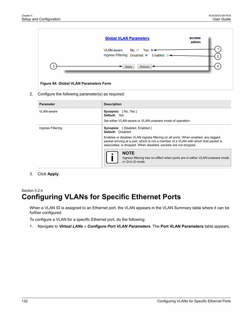
Chapter 5Setup and Configuration
RUGGEDCOM ROSUser Guide
132 Configuring VLANs for Specific Ethernet Ports
43
1
2
Figure 84: Global VLAN Parameters Form
2. Configure the following parameter(s) as required:
Parameter Description
VLAN-aware Synopsis: { No, Yes }Default: Yes
Set either VLAN-aware or VLAN-unaware mode of operation.
Ingress Filtering Synopsis: { Disabled, Enabled }Default: Disabled
Enables or disables VLAN ingress filtering on all ports. When enabled, any taggedpacket arriving at a port, which is not a member of a VLAN with which that packet isassociated, is dropped. When disabled, packets are not dropped.
NOTEIngress filtering has no effect when ports are in either VLAN-unaware modeor Q-in-Q mode.
3. Click Apply.
Section 5.2.4
Configuring VLANs for Specific Ethernet PortsWhen a VLAN ID is assigned to an Ethernet port, the VLAN appears in the VLAN Summary table where it can befurther configured.
To configure a VLAN for a specific Ethernet port, do the following:
1. Navigate to Virtual LANs » Configure Port VLAN Parameters. The Port VLAN Parameters table appears.

RUGGEDCOM ROSUser Guide
Chapter 5Setup and Configuration
Configuring VLANs for Specific Ethernet Ports 133
Figure 85: Port VLAN Parameters Table
2. Select a port. The Port VLAN Parameters form appears.
76
4
3
2
1
5
Figure 86: Port VLAN Parameters Form
1. Port(s) Box 2. Type List 3. PVID Box 4. PVID Format Options 5. GVRP List 6. Apply Button 7. Reload Button
3. Configure the following parameter(s) as required:
Parameter Description
Port(s) Synopsis: Any combination of numbers valid for this parameter
The port number as seen on the front plate silkscreen of the switch (or a list of ports, ifaggregated in a port trunk).
Type Synopsis: { Edge, Trunk, PVLANEdge, QinQ }Default: Edge
This parameter specifies how the port determines its membership in VLANs. There arefew types of ports:
• Edge - the port is only a member of one VLAN (its native VLAN specified by the PVIDparameter).
• Trunk - the port is automatically a member of all configured VLANs. Framestransmitted out of the port on all VLANs except the port's native VLAN will be alwaystagged. It can also be configured to use GVRP for automatic VLAN configuration.

Chapter 5Setup and Configuration
RUGGEDCOM ROSUser Guide
134 Managing Static VLANs
Parameter Description
• PVLANEdge - the port is only a member of one VLAN (its native VLAN specified bythe PVID parameter), and does not forward traffic to other PVLANedge ports withinthe same VLAN.
• QinQ - the port is a trunk port using double-VLAN tagging, or nested VLANs. An extraVLAN tag is always added to all frames egressing this port. VID in the added extratag is the PVID of the frame's ingress port. VLAN tag is always stripped from framesingressing this port.
NOTEQinQ can only be enabled on one switch port at a time.
PVID Synopsis: 1 to 4094Default: 1The Port VLAN Identifier specifies the VLAN ID associated with untagged (and 802.1ppriority tagged) frames received on this port.
Frames tagged with a non-zero VLAN ID will always be associated with the VLAN IDretrieved from the frame tag.
Modify this parameter with care! By default, the switch is programmed to use VLAN 1 formanagement and every port on the switch is programmed to use VLAN 1. If you modifya switch port to use a VLAN other than the management VLAN, devices on that port willnot be able to manage the switch.
PVID Format Synopsis: { Untagged, Tagged }Default: Untagged
Specifies whether frames transmitted out of the port on its native VLAN (specified by thePVID parameter) will be tagged or untagged.
If Type is set to QinQ, set the PVID format to Tagged and make sure all other ports areset to Untagged.
GVRP Synopsis: { Adv&Learn, Adv Only, Disabled }Default: Disabled
Configures GVRP (Generic VLAN Registration Protocol) operation on the port. Thereare several GVRP operation modes:
• DISABLED - the port is not capable of any GVRP processing.• ADVERTISE ONLY - the port will declare all VLANs existing in the switch (configured
or learned) but will not learn any VLANs.• ADVERTISE & LEARN - the port will declare all VLANs existing in the switch
(configured or learned) and can dynamically learn VLANs.
Only Trunk ports are GVRP-capable.
4. Click Apply.
Section 5.2.5
Managing Static VLANsThe following sections describe how to configure and manage static VLANs:
• Section 5.2.5.1, “Viewing a List of Static VLANs”
• Section 5.2.5.2, “Adding a Static VLAN”
• Section 5.2.5.3, “Deleting a Static VLAN”

RUGGEDCOM ROSUser Guide
Chapter 5Setup and Configuration
Viewing a List of Static VLANs 135
Section 5.2.5.1
Viewing a List of Static VLANsTo view a list of static VLANs, navigate to Virtual LANs » Configure Static VLANs. The Static VLANs tableappears.
Figure 87: Static VLANs Table
If a static VLAN is not listed, add the VLAN. For more information, refer to Section 5.2.5.2, “Adding a StaticVLAN”.
Section 5.2.5.2
Adding a Static VLANTo add a static VLAN, do the following:
1. Navigate to Virtual LANs » Configure Static VLANs. The Static VLANs table appears.
1
Figure 88: Static VLANs Table
1. InsertRecord
2. Click InsertRecord. The Static VLANs form appears.

Chapter 5Setup and Configuration
RUGGEDCOM ROSUser Guide
136 Adding a Static VLAN
6
7
8
1
2
3
4
5
Figure 89: Static VLANs Form
1. VID Box 2. VLAN Name Box 3. Forbidden Ports Box 4. IGMP Options 5. MSTI Box 6. Apply Button 7. Delete Button 8. Reload Button
3. Configure the following parameter(s) as required:
NOTEIf IGMP Options is not enabled for the VLAN, both IGMP messages and multicast streams will beforwarded directly to all members of the VLAN. If any one member of the VLAN joins a multicastgroup, then all members of the VLAN will receive the multicast traffic.
Parameter Description
VID Synopsis: 1 to 4094Synopsis: 1 to 4094Default: 1The VLAN Identifier is used to identify the VLAN in tagged Ethernet frames according toIEEE 802.1Q.
VLAN Name Synopsis: Any 19 characters
The VLAN name provides a description of the VLAN purpose (for example, EngineeringVLAN).
Forbidden Ports Synopsis: Any combination of numbers valid for this parameter
These are ports that are not allowed to be members of the VLAN.
Examples:
• None - all ports of the switch are allowed to be members of the VLAN• 2,4-6,8 - all ports except ports 2, 4, 6, 7 and 8 are allowed to be members of the
VLAN
IGMP Synopsis: { Off, On }Default: Off
This parameter enables or disables IGMP Snooping on the VLAN.
MSTI Synopsis: 0 to 16Default: 0

RUGGEDCOM ROSUser Guide
Chapter 5Setup and Configuration
Deleting a Static VLAN 137
Parameter Description
This parameter is only valid for Multiple Spanning Tree Protocol (MSTP) and has noeffect if MSTP is not used. The parameter specifies the Multiple Spanning Tree Instance(MSTI) to which the VLAN should be mapped.
4. Click Apply.
Section 5.2.5.3
Deleting a Static VLANTo delete a static VLAN, do the following:
1. Navigate to Virtual LANs » Configure Static VLANs. The Static VLANs table appears.
Figure 90: Static VLANs Table
2. Select the static VLAN from the table. The Static VLANs form appears.
6
7
8
1
2
3
4
5
Figure 91: Static VLANs Form
1. VID Box 2. VLAN Name Box 3. Forbidden Ports Box 4. IGMP Options 5. MSTI Box 6. Apply Button 7. Delete Button 8. Reload Button
3. Click Delete.

Chapter 5Setup and Configuration
RUGGEDCOM ROSUser Guide
138 Managing Spanning Tree Protocol
Section 5.3
Managing Spanning Tree ProtocolThe following sections describe how to configure and manage STP:
• Section 5.3.1, “RSTP Operation”
• Section 5.3.2, “RSTP Applications”
• Section 5.3.3, “MSTP Operation”
• Section 5.3.4, “Configuring STP Globally”
• Section 5.3.5, “Configuring STP for Specific Ethernet Ports”
• Section 5.3.6, “Configuring eRSTP”
• Section 5.3.7, “Viewing Global Statistics for STP”
• Section 5.3.8, “Viewing STP Statistics for Ethernet Ports”
• Section 5.3.9, “Managing Multiple Spanning Tree Instances”
• Section 5.3.10, “Clearing Spanning Tree Protocol Statistics”
Section 5.3.1
RSTP OperationThe 802.1D Spanning Tree Protocol (STP) was developed to enable the construction of robust networks thatincorporate redundancy while pruning the active topology of the network to prevent loops. While STP is effective,it requires that frame transfer halt after a link outage until all bridges in the network are guaranteed to be aware ofthe new topology. Using the values recommended by 802.1D, this period lasts 30 seconds.
The Rapid Spanning Tree Protocol (RSTP, IEEE 802.1w) was a further evolution of the 802.1D Spanning TreeProtocol. It replaced the settling period with an active handshake between bridges that guarantees the rapidpropagation of topology information throughout the network. RSTP also offers a number of other significantinnovations, including:
• Topology changes in RSTP can originate from and be acted upon by any designated bridges, leading to morerapid propagation of address information, unlike topology changes in STP, which must be passed to the rootbridge before they can be propagated to the network.
• RSTP explicitly recognizes two blocking roles - Alternate and Backup Port - which are included in computationsof when to learn and forward. STP, however, recognizes only one state - Blocking - for ports that should notforward.
• RSTP bridges generate their own configuration messages, even if they fail to receive any from the root bridge.This leads to quicker failure detection. STP, by contrast, must relay configuration messages received on theroot port out its designated ports. If an STP bridge fails to receive a message from its neighbor, it cannot besure where along the path to the root a failure occurred.
• RSTP offers edge port recognition, allowing ports at the edge of the network to forward frames immediatelyafter activation, while at the same time protecting them against loops.
While providing much better performance than STP, IEEE 802.1w RSTP still required up to several seconds torestore network connectivity when a topology change occurred.
A revised and highly optimized RSTP version was defined in the IEEE standard 802.1D-2004 edition. IEEE802.1D-2004 RSTP reduces network recovery times to just milliseconds and optimizes RSTP operation forvarious scenarios.
RUGGEDCOM ROSUser Guide
Chapter 5Setup and Configuration
RSTP States and Roles 139
ROS supports IEEE 802.1D-2004 RSTP.
The following sections further describe the operation of RSTP:
• Section 5.3.1.1, “RSTP States and Roles”
• Section 5.3.1.2, “Edge Ports”
• Section 5.3.1.3, “Point-to-Point and Multipoint Links”
• Section 5.3.1.4, “Path and Port Costs”
• Section 5.3.1.5, “Bridge Diameter”
• Section 5.3.1.6, “eRSTP”
• Section 5.3.1.7, “Fast Root Failover”
Section 5.3.1.1
RSTP States and RolesRSTP bridges have roles to play, either root or designated. One bridge - the Root Bridge - is the logical center ofthe network. All other bridges in the network are Designated bridges. RSTP also assigns each port of the bridgea state and a role. The RSTP state describes what is happening at the port in relation to address learning andframe forwarding. The RSTP role basically describes whether the port is facing the center or the edges of thenetwork and whether it can currently be used.
StateThere are three RSTP states: Discarding, Learning and Forwarding.
The discarding state is entered when the port is first put into service. The port does not learn addresses in thisstate and does not participate in frame transfer. The port looks for RSTP traffic in order to determine its role inthe network. When it is determined that the port will play an active part in the network, the state will change tolearning.
The learning state is entered when the port is preparing to play an active part in the network. The port learnsaddresses in this state but does not participate in frame transfer. In a network of RSTP bridges, the time spent inthis state is usually quite short. RSTP bridges operating in STP compatibility mode will spend six to 40 seconds inthis state.
After learning, the bridge will place the port in the forwarding state. The port both learns addresses andparticipates in frame transfer while in this state.
IMPORTANT!ROS introduces two more states - Disabled and Link Down. Introduced purely for purposes ofmanagement, these states may be considered subclasses of the RSTP Discarding state. The Disabledstate refers to links for which RSTP has been disabled. The Link Down state refers to links for whichRSTP is enabled but are currently down.
RoleThere are four RSTP port roles: Root, Designated, Alternate and Backup. If the bridge is not the root bridge, itmust have a single Root Port. The Root Port is the “best” (i.e. quickest) way to send traffic to the root bridge.
A port is marked as Designated if it is the best port to serve the LAN segment it is connected to. All bridges onthe same LAN segment listen to each others’ messages and agree on which bridge is the Designated Bridge.The ports of other bridges on the segment must become either Root, Alternate or Backup ports.

Chapter 5Setup and Configuration
RUGGEDCOM ROSUser Guide
140 Edge Ports
3
21C
1
2
1
23
3
D
4
2 2
1
3
4
5 6 3
Figure 92: Bridge and Port Roles
1. Root Bridge 2. Designated Bridge 3. Designated Port 4. Root Port 5. Alternate Port 6. Backup Port
A port is alternate when it receives a better message from another bridge on the LAN segment it is connected to.The message that an Alternate Port receives is better than the port itself would generate, but not good enough toconvince it to become the Root Port. The port becomes the alternate to the current Root Port and will become thenew Root Port should the current Root Port fail. The Alternate Port does not participate in the network.
A port is a Backup Port when it receives a better message from the LAN segment it is connected to, originatingfrom another port on the same bridge. The port is a backup for another port on the bridge and will become activeif that port fails. The Backup Port does not participate in the network.
Section 5.3.1.2
Edge PortsA port may be designated as an Edge Port if it is directly connected to an end station. As such, it cannot createbridging loops in the network and can thus directly transition to forwarding, skipping the listening and learningstages.
Edge ports that receive configuration messages immediately lose their Edge Port status and become normalspanning tree ports. A loop created on an improperly connected edge port is thus quickly repaired.
Because an Edge Port services only end stations, topology change messages are not generated when its linktoggles.
RUGGEDCOM ROSUser Guide
Chapter 5Setup and Configuration
Point-to-Point and Multipoint Links 141
Section 5.3.1.3
Point-to-Point and Multipoint LinksRSTP uses a peer-peer protocol called Proposing-Agreeing to ensure transitioning in the event of a link failure.This protocol is point-to-point and breaks down in multipoint situations, i.e. when more than two bridges operateon a shared media link.
If RSTP detects this circumstance (based upon the port’s half duplex state after link up) it will switch offProposing-Agreeing. The port must transition through the learning and forwarding states, spending one forwarddelay in each state.
There are circumstances in which RSTP will make an incorrect decision about the point-to-point state of the linksimply by examining the half-duplex status, namely:
• The port attaches only to a single partner, but through a half-duplex link.
• The port attaches to a shared media hub through a full-duplex link. The shared media link attaches to morethan one RSTP enabled bridge.
In such cases, the user may configure the bridge to override the half-duplex determination mechanism and forcethe link to be treated in the proper fashion.
Section 5.3.1.4
Path and Port CostsThe STP path cost is the main metric by which root and designated ports are chosen. The path cost for adesignated bridge is the sum of the individual port costs of the links between the root bridge and that designatedbridge. The port with the lowest path cost is the best route to the root bridge and is chosen as the root port.
NOTEIn actuality the primary determinant for root port selection is the root bridge ID. Bridge ID is importantmainly at network startup when the bridge with the lowest ID is elected as the root bridge. After startup(when all bridges agree on the root bridge’s ID) the path cost is used to select root ports. If the pathcosts of candidates for the root port are the same, the ID of the peer bridge is used to select the port.Finally, if candidate root ports have the same path cost and peer bridge ID, the port ID of the peerbridge is used to select the root port. In all cases the lower ID, path cost or port ID is selected as thebest.
How Port Costs Are GeneratedPort costs can be generated either as a result of link auto-negotiation or manual configuration. When the linkauto-negotiation method is used, the port cost is derived from the speed of the link. This method is useful whena well-connected network has been established. It can be used when the designer is not too concerned with theresultant topology as long as connectivity is assured.
Manual configuration is useful when the exact topology of the network must be predictable under allcircumstances. The path cost can be used to establish the topology of the network exactly as the designerintends.
STP vs. RSTP CostsThe IEEE 802.1D-1998 specification limits port costs to values of 1 to 65536. Designed at a time when 9600 bpslinks were state of the art, this method breaks down in modern use, as the method cannot represent a link speedhigher than 10 gigabits per second.
To remedy this problem in future applications, the IEEE 802.1w specification limits port costs to values of 1 to20000000, and a link speed up to 10 Tb per second can be represented with a value of 2.
Chapter 5Setup and Configuration
RUGGEDCOM ROSUser Guide
142 Bridge Diameter
RUGGEDCOM bridges support interoperability with legacy STP bridges by selecting the style to use. In practice,it makes no difference which style is used as long as it is applied consistently across the network, or if costs aremanually assigned.
Section 5.3.1.5
Bridge DiameterThe bridge diameter is the maximum number of bridges between any two possible points of attachment of endstations to the network.
The bridge diameter reflects the realization that topology information requires time to propagate hop by hopthrough a network. If configuration messages take too long to propagate end to end through the network, theresult will be an unstable network.
There is a relationship between the bridge diameter and the maximum age parameter. To achieve extended ringsizes, Siemens eRSTP™ uses an age increment of ¼ of a second. The value of the maximum bridge diameter isthus four times the configured maximum age parameter.
NOTEThe RSTP algorithm is as follows:
• STP configuration messages contain age information.
• Messages transmitted by the root bridge have an age of 0. As each subsequent designated bridgetransmits the configuration message it must increase the age by at least 1 second.
• When the age exceeds the value of the maximum age parameter the next bridge to receive themessage immediately discards it.
IMPORTANT!Raise the value of the maximum age parameter if implementing very large bridged networks or rings.
Section 5.3.1.6
eRSTPSiemens's enhanced Rapid Spanning Tree Protocol (eRSTP) improves the performance of RSTP in two ways:
• Improves the fault recovery time performance (< 5 ms per hop)
• Improves performance for large ring network topologies (up to 80 switches)
eRSTP is also compatible with standard RSTP for interoperability with commercial switches.
For example, in a network comprised of 15 RUGGEDCOM hardened Ethernet switches in a ring topology, theexpected fault recovery time would be less than 75 ms (i.e. 5 ms x 15). However, with eRSTP, the worst casefault recovery time is less than 26 ms.
RUGGEDCOM ROSUser Guide
Chapter 5Setup and Configuration
Fast Root Failover 143
Section 5.3.1.7
Fast Root FailoverSiemens’s Fast Root Failover feature is an enhancement to RSTP that may be enabled or disabled. Fast RootFailover improves upon RSTP’s handling of root bridge failures in mesh-connected networks, trading slightlyincreased failover times for a deterministic recovery time.
Two Fast Root Failover algorithms are available:
• Robust: guarantees a deterministic root failover time, but requires support from all switches in the network,including the root switch
• Relaxed: ensures a deterministic root failover time in most network configurations, but allows the use of astandard bridge in the root role
NOTETo use RSTP Fast Root Failover, all switches in the network must be RUGGEDCOM switches andmust have the same Fast Root Failover algorithm enabled. In networks mixing RUGGEDCOM andnon-RUGGEDCOM switches, or in those mixing Fast Root Failover algorithms, RSTP Fast RootFailover will not function properly and root bridge failure will result in an unpredictable failover time.
Fast Root Failover and RSTP Performance• Running RSTP with Fast Root Failover disabled has no impact on RSTP performance.
• Fast Root Failover has no effect on RSTP performance in the case of failures that do not involve the root bridgeor one of its links.
• The extra processing introduced by Fast Root Failover significantly decreases the worst-case failover timein mesh networks, with a modest increase in the best-case failover time. The effect on failover time in ring-connected networks, however, is only to increase it.
Recommendations On the Use of Fast Root Failover• It is not recommended to enable Fast Root Failover in single ring network topologies
• It is strongly recommended to always connect the root bridge to each of its neighbor bridges using more thanone link
Section 5.3.2
RSTP ApplicationsThe following sections describe various applications of RSTP:
• Section 5.3.2.1, “RSTP in Structured Wiring Configurations”
• Section 5.3.2.2, “RSTP in Ring Backbone Configurations”
• Section 5.3.2.3, “RSTP Port Redundancy”
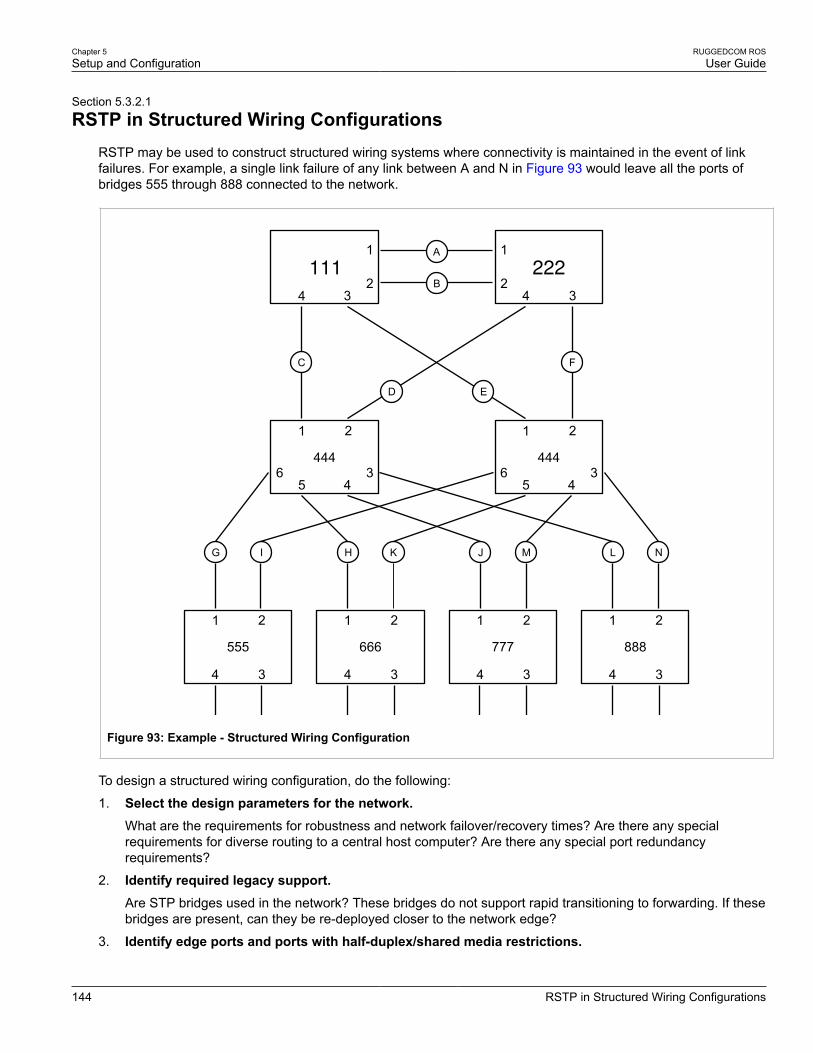
Chapter 5Setup and Configuration
RUGGEDCOM ROSUser Guide
144 RSTP in Structured Wiring Configurations
Section 5.3.2.1
RSTP in Structured Wiring ConfigurationsRSTP may be used to construct structured wiring systems where connectivity is maintained in the event of linkfailures. For example, a single link failure of any link between A and N in Figure 93 would leave all the ports ofbridges 555 through 888 connected to the network.
1
322
11
444
B
A
4
D
3
F
2
4
1
666
3
2
4
1
777
3
2
4
1
888
3
2
4
1
555
3
2
1
444
C
KH
2
E
4
43
56
56
43
IG MJ NL
Figure 93: Example - Structured Wiring Configuration
To design a structured wiring configuration, do the following:
1. Select the design parameters for the network.What are the requirements for robustness and network failover/recovery times? Are there any specialrequirements for diverse routing to a central host computer? Are there any special port redundancyrequirements?
2. Identify required legacy support.Are STP bridges used in the network? These bridges do not support rapid transitioning to forwarding. If thesebridges are present, can they be re-deployed closer to the network edge?
3. Identify edge ports and ports with half-duplex/shared media restrictions.

RUGGEDCOM ROSUser Guide
Chapter 5Setup and Configuration
RSTP in Ring Backbone Configurations 145
Ports that connect to host computers, Intelligent Electronic Devices (IEDs) and controllers may be set toedge ports in order to guarantee rapid transitioning to forwarding as well as to reduce the number of topologychange notifications in the network. Ports with half-duplex/shared media restrictions require special attentionin order to guarantee that they do not cause extended fail-over/recovery times.
4. Choose the root bridge and backup root bridge carefully.The root bridge should be selected to be at the concentration point of network traffic. Locate the backup rootbridge adjacent to the root bridge. One strategy that may be used is to tune the bridge priority to establishthe root bridge and then tune each bridge’s priority to correspond to its distance from the root bridge.
5. Identify desired steady state topology.Identify the desired steady state topology taking into account link speeds, offered traffic and QOS. Examineof the effects of breaking selected links, taking into account network loading and the quality of alternate links.
6. Decide upon a port cost calculation strategy.Select whether fixed or auto-negotiated costs should be used? It is recommended to use the auto-negotiatedcost style, unless it is necessary for the network design to change the auto-negotiated cost style. Selectwhether the STP or RSTP cost style should be used. Make sure to configure the same cost style on alldevices on the network.
7. Enable RSTP Fast Root Failover option.This is a proprietary feature of Siemens . In a mesh network with only RUGGEDCOM devices in the coreof the network, it is recommended to enable the RSTP Fast Root Failover option to minimize the networkdowntime in the event of a Root bridge failure.
8. Calculate and configure priorities and costs.
9. Implement the network and test under load.
Section 5.3.2.2
RSTP in Ring Backbone ConfigurationsRSTP may be used in ring backbone configurations where rapid recovery from link failure is required. In normaloperation, RSTP will block traffic on one of the links, for example, as indicated by the double bars through link Hin Figure 94. In the event of a failure on link D, bridge 444 will unblock link H. Bridge 333 will communicate withthe network through link F.

Chapter 5Setup and Configuration
RUGGEDCOM ROSUser Guide
146 RSTP in Ring Backbone Configurations
E
1
3
31
C
G
A
K
I1
32
2
2 32
1
3321B
J
555
666 333
444
F
L D
H
Figure 94: Example - Ring Backbone Configuration
To design a ring backbone configuration with RSTP, do the following:
1. Select the design parameters for the network.What are the requirements for robustness and network fail-over/recovery times? Typically, ring backbonesare chosen to provide cost effective but robust network designs.
2. Identify required legacy support and ports with half-duplex/shared media restrictions.These bridges should not be used if network fail-over/recovery times are to be minimized.
3. Identify edge ports.Ports that connect to host computers, Intelligent Electronic Devices (IEDs) and controllers may be set toedge ports in order to guarantee rapid transitioning to forwarding as well as to reduce the number of topologychange notifications in the network.
4. Choose the root bridge.The root bridge can be selected to equalize either the number of bridges, number of stations or amount oftraffic on either of its legs. It is important to realize that the ring will always be broken in one spot and thattraffic always flows through the root.
5. Assign bridge priorities to the ring.

RUGGEDCOM ROSUser Guide
Chapter 5Setup and Configuration
RSTP Port Redundancy 147
The strategy that should be used is to assign each bridge’s priority to correspond to its distance from the rootbridge. If the root bridge is assigned the lowest priority of 0, the bridges on either side should use a priorityof 4096 and the next bridges 8192 and so on. As there are 16 levels of bridge priority available, this methodprovides for up to 31 bridges in the ring.
6. Decide upon a port cost calculation strategy.It is recommended to use the auto-negotiated cost style, unless it is necessary for the network design tochange the auto-negotiated cost style. Select whether the STP or RSTP cost style should be used. Makesure to configure the same cost style on all devices on the network.
7. Disable RSTP Fast Root Failover option.This is a proprietary feature of Siemens . In ROS, the RSTP Fast Root Failover option is enabled by default.It is recommended to disable this feature when operating in a Ring network.
8. Implement the network and test under load.
Section 5.3.2.3
RSTP Port RedundancyIn cases where port redundancy is essential, RSTP allows more than one bridge port to service a LAN. In thefollowing example, if port 3 is designated to carry the network traffic of LAN A, port 4 will block traffic. Should aninterface failure occur on port 3, port 4 will assume control of the LAN.
A
1 2
34
Figure 95: Example - Port Redundancy
Section 5.3.3
MSTP OperationThe Multiple Spanning Tree (MST) algorithm and protocol provide greater control and flexibility than RSTP andlegacy STP. MSTP (Multiple Spanning Tree Protocol) is an extension of RSTP, whereby multiple spanning treesmay be maintained on the same bridged network. Data traffic is allocated to one or another of several spanningtrees by mapping one or more VLANs onto the network.
The sophistication and utility of the Multiple Spanning Tree implementation on a given bridged network isproportional to the amount of planning and design invested in configuring MSTP.
If MSTP is activated on some or all of the bridges in a network with no additional configuration, the result will be afully and simply connected network, but at best, the result will be the same as a network using only RSTP. Takingfull advantage of the features offered by MSTP requires a potentially large number of configuration variablesto be derived from an analysis of data traffic on the bridged network, and from requirements for load sharing,

Chapter 5Setup and Configuration
RUGGEDCOM ROSUser Guide
148 MSTP Regions and Interoperability
redundancy, and path optimization. Once these parameters have all been derived, it is also critical that they areconsistently applied and managed across all bridges in an MST region.
By design, MSTP processing time is proportional to the number of active STP instances. This means thatMSTP will likely be significantly slower than RSTP. Therefore, for mission critical applications, RSTP should beconsidered a better network redundancy solution than MSTP.
The following sections further describe the operation of MSTP:
• Section 5.3.3.1, “MSTP Regions and Interoperability”
• Section 5.3.3.2, “MSTP Bridge and Port Roles”
• Section 5.3.3.3, “Benefits of MSTP”
• Section 5.3.3.4, “Implementing MSTP on a Bridged Network”
Section 5.3.3.1
MSTP Regions and InteroperabilityIn addition to supporting multiple spanning trees in a network of MSTP-capable bridges, MSTP is capable ofinter-operating with bridges that support only RSTP or legacy STP, without requiring any special configuration.
An MST region may be defined as the set of interconnected bridges whose MST Region Identification is identical.The interface between MSTP bridges and non-MSTP bridges, or between MSTP bridges with different MSTRegion Identification information, becomes part of an MST Region boundary.
Bridges outside an MST region will see the entire region as though it were a single (R)STP bridge; the internaldetail of the MST region is hidden from the rest of the bridged network. In support of this, MSTP maintainsseparate hop counters for spanning tree information exchanged at the MST region boundary versus thatpropagated inside the region. For information received at the MST region boundary, the (R)STP Message Age isincremented only once. Inside the region, a separate Remaining Hop Count is maintained, one for each spanningtree instance. The external Message Age parameter is referred to the (R)STP Maximum Age Time, whereas theinternal Remaining Hop Counts are compared to an MST region-wide Maximum Hops parameter.
MSTIAn MSTI (Multiple Spanning Tree Instance) is one of sixteen independent spanning tree instances that may bedefined in an MST region (not including the IST – see below). An MSTI is created by mapping a set of VLANs (inROS, via the VLAN configuration) to a given MSTI ID. The same mapping must be configured on all bridges thatare intended to be part of the MSTI. Moreover, all VLAN to MSTI mappings must be identical for all bridges in anMST region.
ROS supports 16 MSTIs in addition to the IST.
Each MSTI has a topology that is independent of every other. Data traffic originating from the same source andbound to the same destination but on different VLANs on different MSTIs may therefore travel a different pathacross the network.
ISTAn MST region always defines an IST (Internal Spanning Tree). The IST spans the entire MST region, andcarries all data traffic that is not specifically allocated (by VLAN) to a specific MSTI. The IST is always computedand is defined to be MSTI zero.
The IST is also the extension inside the MST region of the CIST (see below), which spans the entire bridgednetwork, inside and outside of the MST region and all other RSTP and STP bridges, as well as any other MSTregions.
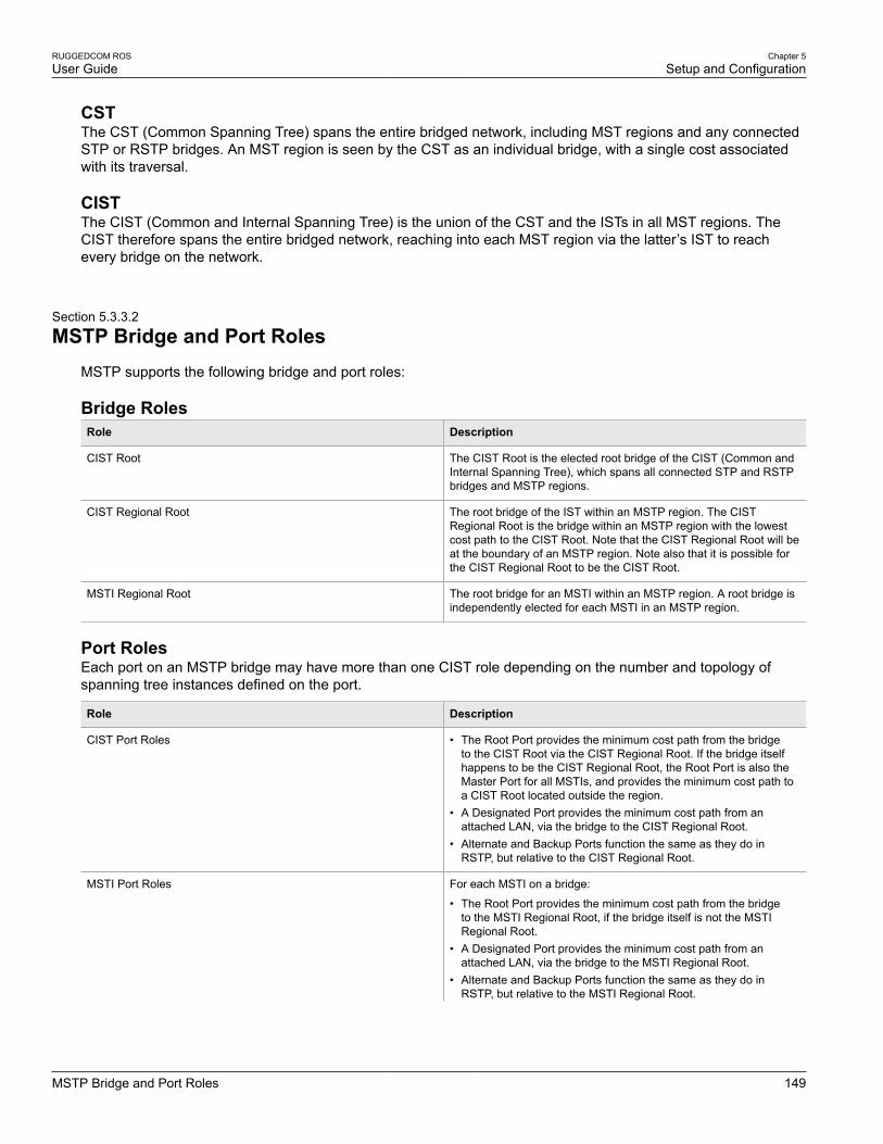
RUGGEDCOM ROSUser Guide
Chapter 5Setup and Configuration
MSTP Bridge and Port Roles 149
CSTThe CST (Common Spanning Tree) spans the entire bridged network, including MST regions and any connectedSTP or RSTP bridges. An MST region is seen by the CST as an individual bridge, with a single cost associatedwith its traversal.
CISTThe CIST (Common and Internal Spanning Tree) is the union of the CST and the ISTs in all MST regions. TheCIST therefore spans the entire bridged network, reaching into each MST region via the latter’s IST to reachevery bridge on the network.
Section 5.3.3.2
MSTP Bridge and Port RolesMSTP supports the following bridge and port roles:
Bridge RolesRole Description
CIST Root The CIST Root is the elected root bridge of the CIST (Common andInternal Spanning Tree), which spans all connected STP and RSTPbridges and MSTP regions.
CIST Regional Root The root bridge of the IST within an MSTP region. The CISTRegional Root is the bridge within an MSTP region with the lowestcost path to the CIST Root. Note that the CIST Regional Root will beat the boundary of an MSTP region. Note also that it is possible forthe CIST Regional Root to be the CIST Root.
MSTI Regional Root The root bridge for an MSTI within an MSTP region. A root bridge isindependently elected for each MSTI in an MSTP region.
Port RolesEach port on an MSTP bridge may have more than one CIST role depending on the number and topology ofspanning tree instances defined on the port.
Role Description
CIST Port Roles • The Root Port provides the minimum cost path from the bridgeto the CIST Root via the CIST Regional Root. If the bridge itselfhappens to be the CIST Regional Root, the Root Port is also theMaster Port for all MSTIs, and provides the minimum cost path toa CIST Root located outside the region.
• A Designated Port provides the minimum cost path from anattached LAN, via the bridge to the CIST Regional Root.
• Alternate and Backup Ports function the same as they do inRSTP, but relative to the CIST Regional Root.
MSTI Port Roles For each MSTI on a bridge:
• The Root Port provides the minimum cost path from the bridgeto the MSTI Regional Root, if the bridge itself is not the MSTIRegional Root.
• A Designated Port provides the minimum cost path from anattached LAN, via the bridge to the MSTI Regional Root.
• Alternate and Backup Ports function the same as they do inRSTP, but relative to the MSTI Regional Root.

Chapter 5Setup and Configuration
RUGGEDCOM ROSUser Guide
150 Benefits of MSTP
Role Description
The Master Port, which is unique in an MSTP region, is the CISTRoot Port of the CIST Regional Root, and provides the minimumcost path to the CIST Root for all MSTIs.
Boundary Ports A Boundary Port is a port on a bridge in an MSTP region thatconnects to either: a bridge belonging to a different MSTP region,or a bridge supporting only RSTP or legacy STP. A Boundary Portblocks or forwards all VLANs from all MSTIs and the CIST alike.
A Boundary Port may be:
• The CIST Root Port of the CIST Regional Root (and thereforealso the MSTI Master Port).
• A CIST Designated Port, CIST Alternate/Backup Port, orDisabled. At the MSTP region boundary, the MSTI Port Role is thesame as the CIST Port Role.
A Boundary Port connected to an STP bridge will send only STPBPDUs. One connected to an RSTP bridge need not refrain fromsending MSTP BPDUs. This is made possible by the fact that theMSTP carries the CIST Regional Root Identifier in the field thatRSTP parses as the Designated Bridge Identifier.
Section 5.3.3.3
Benefits of MSTPDespite the fact that MSTP is configured by default to arrive automatically at a spanning tree solution for eachconfigured MSTI, advantages may be gained from influencing the topology of MSTIs in an MST region. The factthat the Bridge Priority and each port cost are configurable per MST makes it possible to control the topology ofeach MSTI within a region.
Load BalancingMSTP can be used to balance data traffic load among sets of VLANs, enabling more complete utilization of amultiply interconnected bridged network.
A bridged network controlled by a single spanning tree will block redundant links by design, in order to avoidharmful loops. Using MSTP, however, any given link may have a different blocking state for MSTI, as maintainedby MSTP. Any given link, therefore, might be in blocking state for some VLANs, and in forwarding state for otherVLANs, depending on the mapping of VLANs to MSTIs.
It is possible to control the spanning tree solution for each MSTI, especially the set of active links for each tree,by manipulating, per MSTI, the bridge priority and the port costs of links in the network. If traffic is allocatedjudiciously to multiple VLANs, redundant interconnections in a bridged network which, using a single spanningtree, would have gone unused, can now be made to carry traffic.
Isolation of Spanning Tree Reconfiguration.A link failure in an MSTP region that does not affect the roles of Boundary ports will not cause the CST to bereconfigured, nor will the change affect other MSTP regions. This is due to the fact that MSTP information doesnot propagate past a region boundary.
MSTP versus PVSTAn advantage of MSTP over the Cisco Systems Inc. proprietary PVST protocol is the ability to map multipleVLANs onto a single MSTI. Since each spanning tree requires processing and memory, the expense of keepingtrack of an increasing number of VLANs increases much more rapidly for PVST than for MSTP.

RUGGEDCOM ROSUser Guide
Chapter 5Setup and Configuration
Implementing MSTP on a Bridged Network 151
Compatibility with STP and RSTPNo special configuration is required for the bridges of an MST region to connect fully and simply to non-MSTbridges on the same bridged network. Careful planning and configuration is, however, recommended in order toarrive at an optimal network.
Section 5.3.3.4
Implementing MSTP on a Bridged NetworkIt is recommended the configuration of MSTP on a network proceed in the sequence outlined below.
Naturally, it is also recommended that network analysis and planning inform the steps of configuring the VLANand MSTP parameters in particular.
Begin with a set of MSTP-capable Ethernet bridges and MSTP disabled. For each bridge in the network:
NOTEMSTP does not need to be enabled to map a VLAN to an MSTI. However, the mapping must beidentical for each bridge that belongs to the MSTP region.
1. Configure and enable STP globally and/or for specific Ethernet ports. For more information, refer toSection 5.3.4, “Configuring STP Globally” or Section 5.3.5, “Configuring STP for Specific Ethernet Ports”.
NOTEStatic VLANs must be used in an MSTP configuration. GVRP is not supported.
2. Add static VLANs and map them to MSTIs. For more information, refer to Section 5.2.5.2, “Adding a StaticVLAN”.
NOTEThe Region Identifier and Revision Level must be the same for each bridge in the MST region.
3. Configure the revision level for the MST Region Identifier. For more information, refer to Section 5.3.9.3,“Configuring the MST Region Identifier”.
4. Make sure the read-only digest for the MST Region Identifier is identical for each bridge in the MST region. Ifthe digest is different, the set of mappings from VLANs to MSTIs differs.
5. Configure the Bridge Priority for the global MSTI. For more information, refer to Section 5.3.9.4, “Configuringa Global MSTI”.
6. Configure the Port Cost and Priority per Port for each MSTI. For more information, refer to Section 5.3.9.5,“Configuring an MSTI for an Ethernet Port”.
7. Set the STP Protocol Version to MSTP and enable STP. For more information, refer to Section 5.3.4,“Configuring STP Globally”
Section 5.3.4
Configuring STP GloballyTo configure global settings for the Spanning Tree Protocol (STP), do the following:
1. Navigate to Spanning Tree » Configure Bridge RSTP Parameters. The Bridge RSTP Parameters formappears.
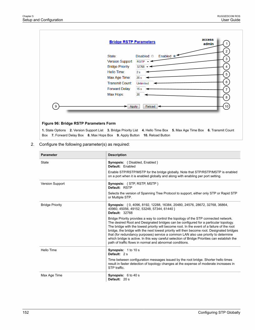
Chapter 5Setup and Configuration
RUGGEDCOM ROSUser Guide
152 Configuring STP Globally
9 10
2
3
4
5
6
7
8
1
Figure 96: Bridge RSTP Parameters Form
1. State Options 2. Version Support List 3. Bridge Priority List 4. Hello Time Box 5. Max Age Time Box 6. Transmit CountBox 7. Forward Delay Box 8. Max Hops Box 9. Apply Button 10. Reload Button
2. Configure the following parameter(s) as required:
Parameter Description
State Synopsis: { Disabled, Enabled }Default: Enabled
Enable STP/RSTP/MSTP for the bridge globally. Note that STP/RSTP/MSTP is enabledon a port when it is enabled globally and along with enabling per port setting.
Version Support Synopsis: { STP, RSTP, MSTP }Default: RSTP
Selects the version of Spanning Tree Protocol to support, either only STP or Rapid STPor Multiple STP.
Bridge Priority Synopsis: { 0, 4096, 8192, 12288, 16384, 20480, 24576, 28672, 32768, 36864,40960, 45056, 49152, 53248, 57344, 61440 }Default: 32768
Bridge Priority provides a way to control the topology of the STP connected network.The desired Root and Designated bridges can be configured for a particular topology.The bridge with the lowest priority will become root. In the event of a failure of the rootbridge, the bridge with the next lowest priority will then become root. Designated bridgesthat (for redundancy purposes) service a common LAN also use priority to determinewhich bridge is active. In this way careful selection of Bridge Priorities can establish thepath of traffic flows in normal and abnormal conditions.
Hello Time Synopsis: 1 to 10 sDefault: 2 s
Time between configuration messages issued by the root bridge. Shorter hello timesresult in faster detection of topology changes at the expense of moderate increases inSTP traffic.
Max Age Time Synopsis: 6 to 40 sDefault: 20 s
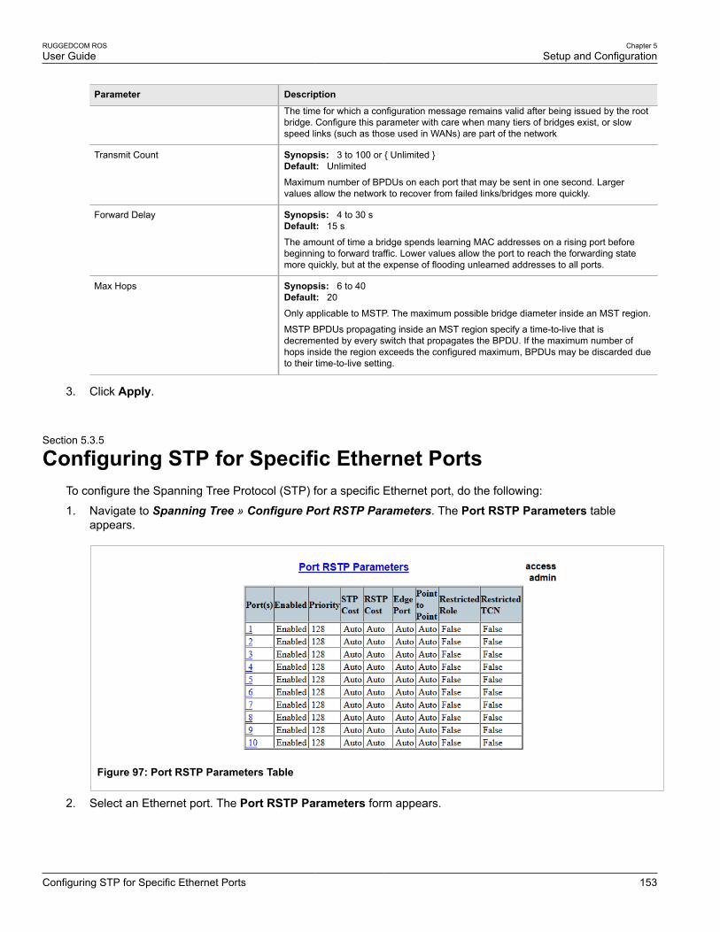
RUGGEDCOM ROSUser Guide
Chapter 5Setup and Configuration
Configuring STP for Specific Ethernet Ports 153
Parameter Description
The time for which a configuration message remains valid after being issued by the rootbridge. Configure this parameter with care when many tiers of bridges exist, or slowspeed links (such as those used in WANs) are part of the network
Transmit Count Synopsis: 3 to 100 or { Unlimited }Default: Unlimited
Maximum number of BPDUs on each port that may be sent in one second. Largervalues allow the network to recover from failed links/bridges more quickly.
Forward Delay Synopsis: 4 to 30 sDefault: 15 s
The amount of time a bridge spends learning MAC addresses on a rising port beforebeginning to forward traffic. Lower values allow the port to reach the forwarding statemore quickly, but at the expense of flooding unlearned addresses to all ports.
Max Hops Synopsis: 6 to 40Default: 20
Only applicable to MSTP. The maximum possible bridge diameter inside an MST region.
MSTP BPDUs propagating inside an MST region specify a time-to-live that isdecremented by every switch that propagates the BPDU. If the maximum number ofhops inside the region exceeds the configured maximum, BPDUs may be discarded dueto their time-to-live setting.
3. Click Apply.
Section 5.3.5
Configuring STP for Specific Ethernet PortsTo configure the Spanning Tree Protocol (STP) for a specific Ethernet port, do the following:
1. Navigate to Spanning Tree » Configure Port RSTP Parameters. The Port RSTP Parameters tableappears.
Figure 97: Port RSTP Parameters Table
2. Select an Ethernet port. The Port RSTP Parameters form appears.

Chapter 5Setup and Configuration
RUGGEDCOM ROSUser Guide
154 Configuring STP for Specific Ethernet Ports
8
10
7
6
5
4
3
2
1
11
9
Figure 98: Port RSTP Parameters Form
1. Port(s) Box 2. Enabled Options 3. Priority List 4. STP Cost Box 5. RSTP Cost Box 6. Edge Port List 7. Point to PointList 8. Restricted Role Box 9. Restricted TCN Box 10. Apply Button 11. Reload Button
3. Configure the following parameter(s) as required:
Parameter Description
Port(s) Synopsis: Any combination of numbers valid for this parameter
The port number as seen on the front plate silkscreen of the switch (or a list of ports, ifaggregated in a port trunk).
Enabled Synopsis: { Disabled, Enabled }Default: Enabled
Enabling STP activates the STP or RSTP protocol for this port per the configuration inthe STP Configuration menu. STP may be disabled for the port ONLY if the port doesnot attach to an STP enabled bridge in any way. Failure to meet this requirement WILLresult in an undetectable traffic loop in the network. A better alternative to disabling theport is to leave STP enabled but to configure the port as an edge port. A good candidatefor disabling STP would be a port that services only a single host computer.
Priority Synopsis: { 0, 16, 32, 48, 64, 80, 96, 112, 128, 144, 160, 176, 194, 208, 224, 240 }Default: 128
Selects the STP port priority. Ports of the same cost that attach to a common LAN willselect the port to be used based upon the port priority.
STP Cost Synopsis: 0 to 65535 or { Auto }Default: Auto
Selects the cost to use in cost calculations, when the Cost Style parameter is set to STPin the Bridge RSTP Parameters configuration. Setting the cost manually provides theability to preferentially select specific ports to carry traffic over others. Leave this fieldset to "auto" to use the standard STP port costs as negotiated (4 for 1Gbps, 19 for 100Mbps links and 100 for 10 Mbps links).
For MSTP, this parameter applies to both external and internal path cost.
RSTP Cost Synopsis: 0 to 2147483647 or { Auto }Default: Auto
Selects the cost to use in cost calculations, when the Cost Style parameter is set toRSTP in the Bridge RSTP Parameters configuration. Setting the cost manually provides

RUGGEDCOM ROSUser Guide
Chapter 5Setup and Configuration
Configuring eRSTP 155
Parameter Description
the ability to preferentially select specific ports to carry traffic over others. Leave thisfield set to "auto" to use the standard RSTP port costs as negotiated (20,000 for 1Gbps,200,000 for 100 Mbps links and 2,000,000 for 10 Mbps links).
For MSTP, this parameter applies to both external and internal path cost.
Edge Port Synopsis: { False, True, Auto }Default: Auto
Edge ports are ports that do not participate in the Spanning Tree, but still sendconfiguration messages. Edge ports transition directly to frame forwarding withoutany listening and learning delays. The MAC tables of Edge ports do not need to beflushed when topology changes occur in the STP network. Unlike an STP disabled port,accidentally connecting an edge port to another port in the spanning tree will result in adetectable loop. The "Edgeness" of the port will be switched off and the standard RSTPrules will apply (until the next link outage).
Point to Point Synopsis: { False, True, Auto }Default: Auto
RSTP uses a peer-to-peer protocol that provides rapid transitioning on point-to-pointlinks. This protocol is automatically turned off in situations where multiple STP bridgescommunicate over a shared (non point-to-point) LAN. The bridge will automatically takepoint-to-point to be true when the link is found to be operating in full-duplex mode. Thepoint-to-point parameter allows this behavior or overrides it, forcing point-to-point tobe true or false. Force the parameter true when the port operates a point-to-point linkbut cannot run the link in full-duplex mode. Force the parameter false when the portoperates the link in full-duplex mode, but is still not point-to-point (e.g. a full-duplex linkto an unmanaged bridge that concentrates two other STP bridges).
Restricted Role Synopsis: { True or False }Default: False
A boolean value set by management. If TRUE, causes the Port not to be selected as theRoot Port for the CIST or any MSTI, even if it has the best spanning tree priority vector.Such a Port will be selected as an Alternate Port after the Root Port has been selected.This parameter should be FALSE by default. If set, it can cause a lack of spanning treeconnectivity. It is set by a network administrator to prevent bridges that are external toa core region of the network from influencing the spanning tree active topology. Thismay be necessary, for example, if those bridges are not under the full control of theadministrator.
Restricted TCN Synopsis: { True or False }Default: False
A boolean value set by management. If TRUE, it causes the Port not to propagatereceived topology change notifications and topology changes to other Ports. If set,it can cause temporary loss of connectivity after changes in a spanning tree’s activetopology as a result of persistent, incorrectly learned, station location information. Itis set by a network administrator to prevent bridges that are external to a core regionof the network from causing address flushing in that region. This may be necessary,for example, if those bridges are not under the full control of the administrator or if theMAC_Operational status parameter for the attached LANs transitions frequently.
4. Click Apply.
Section 5.3.6
Configuring eRSTPTo configure eRSTP, do the following:
1. Navigate to Spanning Tree » Configure eRSTP Parameters. The eRSTP Parameters form appears.

Chapter 5Setup and Configuration
RUGGEDCOM ROSUser Guide
156 Configuring eRSTP
76
5
4
3
2
1
Figure 99: eRSTP Parameters Form
1. Max Network Diameter Options 2. BPDU Guart Timeout Box 3. Fast Root Failover List 4. IEEE802.1w InteroperabilityOptions 5. Cost Style Options 6. Apply Button 7. Reload Button
2. Configure the following parameter(s) as required:
Parameter Description
Max Network Diameter Synopsis: { MaxAgeTime, 4*MaxAgeTime }Default: 4*MaxAgeTime
The RSTP standard puts a limit on the maximum network size that can be controlledby the RSTP protocol. The network size is described by the term 'maximum networkdiameter', which is the number of switches that comprise the longest path that RSTPBPDUs have to traverse. The standard supported maximum network diameter is equalto the value of the 'MaxAgeTime' RSTP configuration parameter.
eRSTP offers an enhancement to RSTP which allows it to cover networks larger thanones defined by the standard.
This configuration parameter selects the maximum supported network size.
BPDU Guard Timeout Synopsis: 1 to 86400 s or { Until reset, Don't shutdown }Default: Don't shutdown
The RSTP standard does not address network security. RSTP must process everyreceived BPDU and take an appropriate action. This opens a way for an attacker toinfluence RSTP topology by injecting RSTP BPDUs into the network.
BPDU Guard is a feature that protects the network from BPDUs received by a portwhere RSTP capable devices are not expected to be attached. If a BPDU is received bya port for which 'Edge' parameter is set to 'TRUE' or RSTP is disabled, the port will beshutdown for the time period specified by this parameter.
• DON'T SHUTDOWN - BPDU Guard is disabled• UNTIL RESET - port will remain shutdown until the port reset command is issued by
the user
Fast Root Failover Synopsis: { On, On with standard root, Off }Default: On
In mesh network topologies, the standard RSTP algorithm does not guaranteedeterministic network recovery time in the case of a root switch failure. Such a recoverytime is hard to calculate and it can be different (and may be relatively long) for any givenmesh topology.
This configuration parameter enables Siemens's enhancement to RSTP which detects afailure of the root switch and performs some extra RSTP processing steps, significantlyreducing the network recovery time and making it deterministic.
NOTE• This feature is only available in RSTP mode. In MSTP mode, the
configuration parameter is ignored.

RUGGEDCOM ROSUser Guide
Chapter 5Setup and Configuration
Viewing Global Statistics for STP 157
Parameter Description
• In a single ring topology, this feature is not needed and should bedisabled to avoid longer network recovery times due to extra RSTPprocessing.
The Fast Root Failover algorithm must be supported by all switches in the network,including the root, to guarantee optimal performance. However, it is not uncommon toassign the root role to a switch from a vendor different from the rest of the switches inthe network. In other words, it is possible that the root might not suport the Fast RootFailover algorithm. In such a scenario, a "relaxed" algorithm should be used, whichtolerates the lack of support in the root switch.
These are the supported configuration options:
• Off - Fast Root Failover algorithm is disabled and hence a root switch failure mayresult in excessive connectivity recovery time.
• On - Fast Root Failover is enabled and the most robust algorithm is used, whichrequires the appropriate support in the root switch.
• On with standard root - Fast Root Failover is enabled but a "relaxed" algorithm isused, allowing the use of a standard switch in the root role.
IEEE802.1w Interoperability Synopsis: { On, Off }Default: On
The original RSTP protocol defined in the IEEE 802.1w standard has minor differencesfrom more recent, enhanced, standard(s). Those differences cause interoperabilityissues which, although they do not completely break RSTP operation, can lead to alonger recovery time from failures in the network.
eRSTP offers some enhancements to the protocol which make the switch fullyinteroperable with other vendors' switches, which may be running IEEE 802.2w RSTP.The enhancements do not affect interoperability with more recent RSTP editions.
This configuration parameter enables the aforementioned interoperability mode.
Cost Style Synopsis: { STP (16 bit), RSTP (32 bit) }Default: STP (16 bit)
The RSTP standard defines two styles of a path cost value. STP uses 16-bit path costsbased upon 1x10E9/link speed (4 for 1Gbps, 19 for 100 Mbps and 100 for 10 Mbps)whereas RSTP uses 32-bit costs based upon 2x10E13/link speed (20,000 for 1Gbps,200,000 for 100 Mbps and 2,000,000 for 10 Mbps). However, switches from somevendors keep using the STP path cost style even in RSTP mode, which can causeconfusion and interoperability problems.
This configuration parameter selects the style of link costs to employ.
Note that RSTP link costs are used only when the bridge version support is set to allowRSTP and the port does not migrate to STP.
3. Click Apply.
Section 5.3.7
Viewing Global Statistics for STPTo view global statistics for STP, navigate to Spanning Tree » View Bridge RSTP Statistics. The Bridge RSTPStatistics form appears.

Chapter 5Setup and Configuration
RUGGEDCOM ROSUser Guide
158 Viewing Global Statistics for STP
Figure 100: Bridge RSTP Statistics Form
This table displays the following information:
Parameter Description
Bridge Status Synopsis: { , Designated Bridge, Not Designated For Any LAN, Root Bridge }
Spanning Tree status of the bridge. The status may be root or designated. This field mayshow text saying not designated for any LAN if the bridge is not designated for any of itsports.
Bridge ID Synopsis: $$ / ##-##-##-##-##-## where $$ is 0 to 65535, ## is 0 to FF
Bridge Identifier of this bridge.
Root ID Synopsis: $$ / ##-##-##-##-##-## where $$ is 0 to 65535, ## is 0 to FF
Bridge Identifier of the root bridge.
Root Port Synopsis: 1 to maximum port number or { <empty string> }
If the bridge is designated, this is the port that provides connectivity towards the root bridgeof the network.
Root Path Cost Synopsis: 0 to 4294967295
Total cost of the path to the root bridge composed of the sum of the costs of each link in thepath. If custom costs have not been configured. 1Gbps ports will contribute 4, 100 Mbpsports will contribute 19 and 10 Mbps ports will contribute a cost of 100 to this figure.
For the CIST instance of MSTP, this is an external root path cost, which is the cost of thepath from the IST root (i.e. regional root) bridge to the CST root (i.e. network "global" root)bridge.
Configured Hello Time Synopsis: 0 to 65535
The configured Hello time from the Bridge RSTP Parameters menu.
Learned Hello Time Synopsis: 0 to 65535
The actual Hello time provided by the root bridge as learned in configuration messages.This time is used in designated bridges.
Configured Forward Delay Synopsis: 0 to 65535
The configured Forward Delay time from the Bridge RSTP Parameters menu.
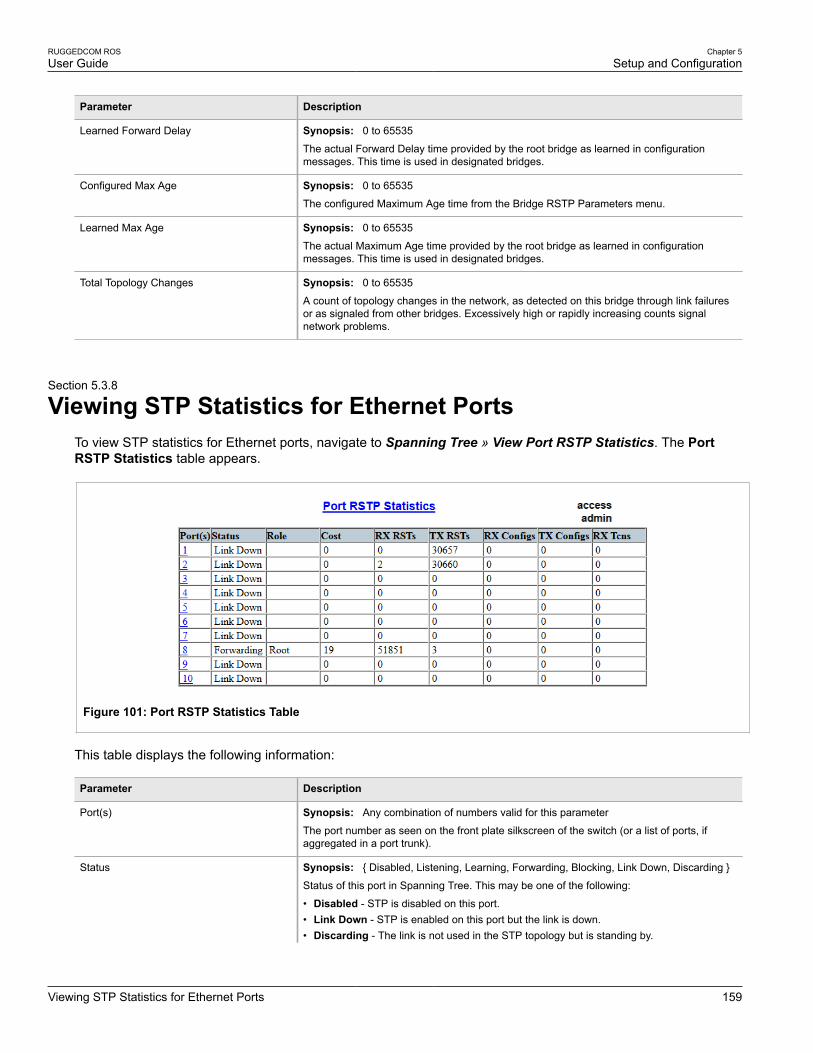
RUGGEDCOM ROSUser Guide
Chapter 5Setup and Configuration
Viewing STP Statistics for Ethernet Ports 159
Parameter Description
Learned Forward Delay Synopsis: 0 to 65535
The actual Forward Delay time provided by the root bridge as learned in configurationmessages. This time is used in designated bridges.
Configured Max Age Synopsis: 0 to 65535
The configured Maximum Age time from the Bridge RSTP Parameters menu.
Learned Max Age Synopsis: 0 to 65535
The actual Maximum Age time provided by the root bridge as learned in configurationmessages. This time is used in designated bridges.
Total Topology Changes Synopsis: 0 to 65535
A count of topology changes in the network, as detected on this bridge through link failuresor as signaled from other bridges. Excessively high or rapidly increasing counts signalnetwork problems.
Section 5.3.8
Viewing STP Statistics for Ethernet PortsTo view STP statistics for Ethernet ports, navigate to Spanning Tree » View Port RSTP Statistics. The PortRSTP Statistics table appears.
Figure 101: Port RSTP Statistics Table
This table displays the following information:
Parameter Description
Port(s) Synopsis: Any combination of numbers valid for this parameter
The port number as seen on the front plate silkscreen of the switch (or a list of ports, ifaggregated in a port trunk).
Status Synopsis: { Disabled, Listening, Learning, Forwarding, Blocking, Link Down, Discarding }
Status of this port in Spanning Tree. This may be one of the following:
• Disabled - STP is disabled on this port.• Link Down - STP is enabled on this port but the link is down.• Discarding - The link is not used in the STP topology but is standing by.
Chapter 5Setup and Configuration
RUGGEDCOM ROSUser Guide
160 Managing Multiple Spanning Tree Instances
Parameter Description
• Learning - The port is learning MAC addresses in order to prevent flooding when itbegins forwarding traffic.
• Forwarding - The port is forwarding traffic.
Role Synopsis: { , Root, Designated, Alternate, Backup, Master }
Role of this port in Spanning Tree. This may be one of the following:
• Designated - The port is designated for (i.e. carries traffic towards the root for) the LAN itis connected to.
• Root - The single port on the bridge, which provides connectivity towards the root bridge.• Backup - The port is attached to a LAN that is serviced by another port on the bridge. It is
not used but is standing by.• Alternate - The port is attached to a bridge that provides connectivity to the root bridge. It
is not used but is standing by.• Master - Only exists in MSTP. The port is an MST region boundary port and the single
port on the bridge, which provides connectivity for the Multiple Spanning Tree Instancetowards the Common Spanning Tree root bridge (i.e. this port is the root port for theCommon Spanning Tree Instance).
Cost Synopsis: 0 to 4294967295
Cost offered by this port. If the Bridge RSTP Parameters Cost Style is set to STP, 1Gbpsports will contribute 4, 100 Mbps ports will contribute 19 and 10 Mbps ports contribute a costof 100. If the Cost Style is set to RSTP, 1Gbps will contribute 20,000, 100 Mbps ports willcontribute a cost of 200,000 and 10 Mbps ports contribute a cost of 2,000,000. Note thateven if the Cost style is set to RSTP, a port that migrates to STP will have its cost limited toa maximum of 65535.
RX RSTs Synopsis: 0 to 4294967295
The count of RSTP configuration messages received on this port.
TX RSTs Synopsis: 0 to 4294967295
The count of RSTP configuration messages transmitted on this port.
RX Configs Synopsis: 0 to 4294967295
The count of STP configuration messages received on this port.
TX Configs Synopsis: 0 to 4294967295
The count of STP configuration messages transmitted on this port.
RX Tcns Synopsis: 0 to 4294967295
The count of STP topology change notification messages received on this port. Excessivelyhigh or rapidly increasing counts signal network problems.
TX Tcns Synopsis: 0 to 4294967295
The count of STP topology change notification messages transmitted on this port.
Desig Bridge ID Synopsis: $$ / ##-##-##-##-##-## where $$ is 0 to 65535, ## is 0 to FF
Provided on the root ports of designated bridges, the Bridge Identifier of the bridge this portis connected to.
operEdge Synopsis: True or False
The port is operating as an edge port or not.
Section 5.3.9
Managing Multiple Spanning Tree InstancesThe following sections describe how to configure and manage Multiple Spanning Tree Instances:
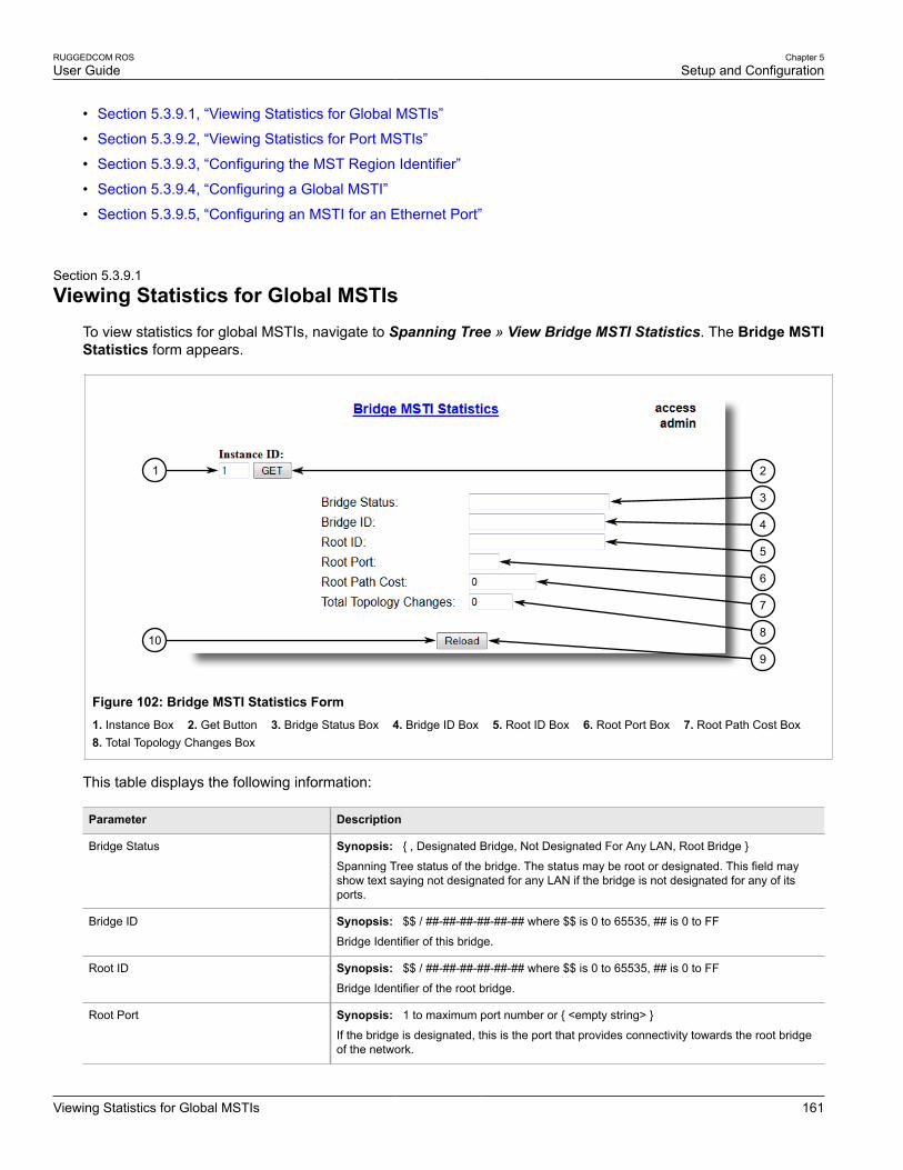
RUGGEDCOM ROSUser Guide
Chapter 5Setup and Configuration
Viewing Statistics for Global MSTIs 161
• Section 5.3.9.1, “Viewing Statistics for Global MSTIs”
• Section 5.3.9.2, “Viewing Statistics for Port MSTIs”
• Section 5.3.9.3, “Configuring the MST Region Identifier”
• Section 5.3.9.4, “Configuring a Global MSTI”
• Section 5.3.9.5, “Configuring an MSTI for an Ethernet Port”
Section 5.3.9.1
Viewing Statistics for Global MSTIsTo view statistics for global MSTIs, navigate to Spanning Tree » View Bridge MSTI Statistics. The Bridge MSTIStatistics form appears.
21
10
3
4
5
6
7
8
9
Figure 102: Bridge MSTI Statistics Form1. Instance Box 2. Get Button 3. Bridge Status Box 4. Bridge ID Box 5. Root ID Box 6. Root Port Box 7. Root Path Cost Box 8. Total Topology Changes Box
This table displays the following information:
Parameter Description
Bridge Status Synopsis: { , Designated Bridge, Not Designated For Any LAN, Root Bridge }
Spanning Tree status of the bridge. The status may be root or designated. This field mayshow text saying not designated for any LAN if the bridge is not designated for any of itsports.
Bridge ID Synopsis: $$ / ##-##-##-##-##-## where $$ is 0 to 65535, ## is 0 to FF
Bridge Identifier of this bridge.
Root ID Synopsis: $$ / ##-##-##-##-##-## where $$ is 0 to 65535, ## is 0 to FF
Bridge Identifier of the root bridge.
Root Port Synopsis: 1 to maximum port number or { <empty string> }
If the bridge is designated, this is the port that provides connectivity towards the root bridgeof the network.

Chapter 5Setup and Configuration
RUGGEDCOM ROSUser Guide
162 Viewing Statistics for Port MSTIs
Parameter Description
Root Path Cost Synopsis: 0 to 4294967295
Total cost of the path to the root bridge composed of the sum of the costs of each link in thepath. If custom costs have not been configured. 1Gbps ports will contribute 4, 100 Mbpsports will contribute 19 and 10 Mbps ports will contribute a cost of 100 to this figure.
For the CIST instance of MSTP, this is an external root path cost, which is the cost of thepath from the IST root (i.e. regional root) bridge to the CST root (i.e. network "global" root)bridge.
Total Topology Changes Synopsis: 0 to 65535
A count of topology changes in the network, as detected on this bridge through link failuresor as signaled from other bridges. Excessively high or rapidly increasing counts signalnetwork problems.
Section 5.3.9.2
Viewing Statistics for Port MSTIsTo view statistics for port MSTIs, navigate to Spanning Tree » View Port MSTI Statistics. The Port MSTIStatistics form appears.
21
Figure 103: Port MSTI Statistics Form
1. Port(s) 2. Status 3. Role 4. Cost 5. Designated Bridge ID
This table displays the following information:
Parameter Description
Port(s) Synopsis: Any combination of numbers valid for this parameter
The port number as seen on the front plate silkscreen of the switch (or a list of ports, ifaggregated in a port trunk).
Status Synopsis: { Disabled, Listening, Learning, Forwarding, Blocking, Link Down, Discarding }
tatus of this port in Spanning Tree. This may be one of the following:

RUGGEDCOM ROSUser Guide
Chapter 5Setup and Configuration
Configuring the MST Region Identifier 163
Parameter Description
• Disabled - STP is disabled on this port.• Link Down - STP is enabled on this port but the link is down.• Discarding - The link is not used in the STP topology but is standing by.• Learning - The port is learning MAC addresses in order to prevent flooding when it
begins forwarding traffic.• Forwarding - The port is forwarding traffic.
Role Synopsis: { , Root, Designated, Alternate, Backup, Master }
Role of this port in Spanning Tree. This may be one of the following:
• Designated - The port is designated for (i.e. carries traffic towards the root for) the LAN itis connected to.
• Root - The single port on the bridge, which provides connectivity towards the root bridge.• Backup - The port is attached to a LAN that is serviced by another port on the bridge. It is
not used but is standing by.• Alternate - The port is attached to a bridge that provides connectivity to the root bridge. It
is not used but is standing by.• Master - Only exists in MSTP. The port is an MST region boundary port and the single
port on the bridge, which provides connectivity for the Multiple Spanning Tree Instancetowards the Common Spanning Tree root bridge (i.e. this port is the root port for theCommon Spanning Tree Instance).
Cost Synopsis: 0 to 4294967295
Cost offered by this port. If the Bridge RSTP Parameters Cost Style is set to STP, 1Gbpsports will contribute 4, 100 Mbps ports will contribute 19 and 10 Mbps ports contribute a costof 100. If the Cost Style is set to RSTP, 1Gbps will contribute 20,000, 100 Mbps ports willcontribute a cost of 200,000 and 10 Mbps ports contribute a cost of 2,000,000. Note thateven if the Cost style is set to RSTP, a port that migrates to STP will have its cost limited toa maximum of 65535.
Desig Bridge ID Synopsis: $$ / ##-##-##-##-##-## where $$ is 0 to 65535, ## is 0 to FF
Provided on the root ports of designated bridges, the Bridge Identifier of the bridge this portis connected to.
Section 5.3.9.3
Configuring the MST Region IdentifierConfiguring the region identifier and revision level puts the MSTP bridge in a defined group. Other bridges thathave the same identifier and revision level are interconnected within this region. For more information, refer toSection 5.3.3.1, “MSTP Regions and Interoperability”.
To configure the Multiple Spanning Tree (MST) region identifier, do the following:
1. Navigate to Spanning Tree » Configure MST Region Identifier. The MST Region Identifier form appears.

Chapter 5Setup and Configuration
RUGGEDCOM ROSUser Guide
164 Configuring a Global MSTI
54
3
2
1
Figure 104: MST Region Identifier Form
1. Name Box 2. Revision Level Box 3. Digest Box 4. Apply Button 5. Reload Button
2. Configure the following parameter(s) as required:
Parameter Description
Name Synopsis: Any 32 charactersDefault: 00-0A-DC-11-12-21
Variable length text string. You must configure an identical region name on all switchesyou want to be in the same MST region.
Revision Level Synopsis: 0 to 65535Default: 0Use this parameter, if you want to create a new region from a subset of switches in acurrent region, while maintaining the same region name.
Digest Synopsis: Any 32 charactersDefault: 0This is a read-only parameter and should be only used for network troubleshooting. Inorder to ensure consistent VLAN-to-instance mapping, it is necessary for the protocolto be able to exactly identify the boundaries of the MST regions. For that pupose, thecharacteristics of the region are included in BPDUs. There is no need to propagate theexact VLAN-to-instance mapping in the BPDUs because switches only need to knowwhether they are in the same region as a neighbor. Therefore, only this 16-octet digestcreated from the VLAN-to-instance mapping is sent in BPDUs.
3. Click Apply.
Section 5.3.9.4
Configuring a Global MSTITo configure a global Multiple Spanning Tree Instance (MSTI) for the Spanning Tree Protocol (STP), do thefollowing:
1. Navigate to Spanning Tree » Configure Bridge MSTI Parameters. The Bridge MSTI Parameters formappears.

RUGGEDCOM ROSUser Guide
Chapter 5Setup and Configuration
Configuring an MSTI for an Ethernet Port 165
54
3
21
Figure 105: Bridge MSTI Parameters Form
1. Instance ID Box 2. Get Button 3. Bridge Priority List 4. Apply Button 5. Reload Button
2. Under Instance ID, type an ID number for a Multiple Spanning Tree Instance (MSTI) and click GET. Thesettings for the MSTI are displayed. Any changes made to the configuration will be applied specifically to thisinstance ID.
3. Configure the following parameter(s) as required:
Parameter Description
Bridge Priority Synopsis: { 0, 4096, 8192, 12288, 16384, 20480, 24576, 28672, 32768, 36864,40960, 45056, 49152, 53248, 57344, 61440 }Default: 32768
Bridge Priority provides a way to control the topology of the STP connected network.The desired Root and Designated bridges can be configured for a particular topology.The bridge with the lowest priority will become root. In the event of a failure of the rootbridge, the bridge with the next lowest priority will then become root. Designated bridgesthat (for redundancy purposes) service a common LAN also use priority to determinewhich bridge is active. In this way careful selection of Bridge Priorities can establish thepath of traffic flows in normal and abnormal conditions.
4. Click Apply.
Section 5.3.9.5
Configuring an MSTI for an Ethernet PortTo configure a Multiple Spanning Tree Instance (MSTI) for an Ethernet port, do the following
1. Navigate to Spanning Tree » Configure Port MSTI Parameters. The Port MSTI Parameters tableappears.

Chapter 5Setup and Configuration
RUGGEDCOM ROSUser Guide
166 Configuring an MSTI for an Ethernet Port
Figure 106: Port MSTI Parameters Table
2. Select an Ethernet port. The Port MSTI Parameters form appears.
6
7
5
4
3
21
8
Figure 107: Port MSTI Parameters Form
1. Instance ID Box 2. Get Button 3. Port(s) Box 4. Priority List 5. STP Cost Box 6. RSTP Cost Box 7. Apply Button 8. Reload Button
3. Under Instance ID, type an ID number for a Multiple Spanning Tree Instance (MSTI) and click GET. Thesettings for the MSTI are displayed. Any changes made to the configuration will be applied specifically to thisinstance ID.
4. Configure the following parameter(s) as required:
Parameter Description
Port(s) Synopsis: Any combination of numbers valid for this parameter
The port number as seen on the front plate silkscreen of the switch (or a list of ports, ifaggregated in a port trunk).

RUGGEDCOM ROSUser Guide
Chapter 5Setup and Configuration
Clearing Spanning Tree Protocol Statistics 167
Parameter Description
Priority Synopsis: { 0, 16, 32, 48, 64, 80, 96, 112, 128, 144, 160, 176, 192, 208, 224, 240 }Default: 128
Selects the STP port priority. Ports of the same cost that attach to a common LAN willselect the port to be used based upon the port priority.
STP Cost Synopsis: 0 to 65535 or { Auto }Default: Auto
Selects the cost to use in cost calculations, when the Cost Style parameter is set to STPin the Bridge RSTP Parameters configuration. Setting the cost manually provides theability to preferentially select specific ports to carry traffic over others. Leave this fieldset to "auto" to use the standard STP port costs as negotiated (4 for 1Gbps, 19 for 100Mbps links and 100 for 10 Mbps links).
For MSTP, this parameter applies to both external and internal path cost.
RSTP Cost Synopsis: 0 to 2147483647 or { Auto }Default: Auto
Selects the cost to use in cost calculations, when the Cost Style parameter is set toRSTP in the Bridge RSTP Parameters configuration. Setting the cost manually providesthe ability to preferentially select specific ports to carry traffic over others. Leave thisfield set to "auto" to use the standard RSTP port costs as negotiated (20,000 for 1Gbps,200,000 for 100 Mbps links and 2,000,000 for 10 Mbps links).
For MSTP, this parameter applies to both external and internal path cost.
5. Click Apply.
Section 5.3.10
Clearing Spanning Tree Protocol StatisticsTo clear all spanning tree protocol statistics, do the following:
1. Navigate to Spanning Tree » Clear Spanning Tree Statistics. The Clear Spanning Tree Statistics formappears.
1
Figure 108: Clear Spanning Tree Statistics Form
1. Confirm Button
2. Click Confirm.
Chapter 5Setup and Configuration
RUGGEDCOM ROSUser Guide
168 Managing Classes of Service
Section 5.4
Managing Classes of ServiceClasses of Service (CoS) provides the ability to expedite the transmission of certain frames and port traffic overothers. The CoS of a frame can be set to Normal, Medium, High, or Critical. By default, other than the controlframes, ROS enforces Normal CoS for all incoming traffic received without a priority tag.
IMPORTANT!Use the highest supported CoS with caution, as it is always used by the switch for handling networkmanagement traffic, such as RSTP BPDUs.
If this CoS is used for regular network traffic, upon traffic bursts, it may result in the loss of somenetwork management frames, which in turn may result in the loss of connectivity over the network.
The process of controlling traffic based on CoS occurs over two phases:
1. Inspection PhaseIn the inspection phase, the CoS priority of a received frame is determined from either:
• A specific CoS based upon the source and destination MAC address (as set in the Static MAC AddressTable)
• The priority field in the IEEE 802.1Q tags
• The Differentiated Services Code Point (DSCP) component of the Type Of Service (TOS) field in the IPheader, if the frame is IP
• The default CoS for the port
Each frame’s CoS will be determined once the first examined parameter is found in the frame.
NOTEFor information on how to configure the Inspect TOS parameter, refer to Section 5.4.2,“Configuring Classes of Service for Specific Ethernet Ports”.
Received frames are first examined to determine if their destination or source MAC address is found in theStatic MAC Address Table. If they are, the CoS configured for the static MAC address is used. If neitherdestination or source MAC address is in the Static MAC Address Table, the frame is then examined forIEEE 802.1Q tags and the priority field is mapped to a CoS. If a tag is not present, the frame is examinedto determine if it is an IP frame. If the frame is an IP frame and Inspect TOS is enabled in ROS, the CoS isdetermined from the DSCP field. If the frame is not an IP frame or Inspect TOS is disabled, the default CoSfor the port is used.
After inspection, the frame is forwarded to the egress port for transmission.
2. Forwarding PhaseOnce the CoS of the frame is determined, the frame is forwarded to the egress port, where it is collected intoone of the priority queues according to the assigned CoS.
CoS weighting selects the degree of preferential treatment that is attached to different priority queues. Theratio of the number of higher CoS to lower CoS frames transmitted can be configured. If desired, lower CoSframes can be transmitted only after all higher CoS frames have been serviced.
The following sections describe how to configure and manage Classes of Service:
• Section 5.4.1, “Configuring Classes of Service Globally”
• Section 5.4.2, “Configuring Classes of Service for Specific Ethernet Ports”
• Section 5.4.3, “Configuring Priority to CoS Mapping”

RUGGEDCOM ROSUser Guide
Chapter 5Setup and Configuration
Configuring Classes of Service Globally 169
• Section 5.4.4, “Configuring DSCP to CoS Mapping”
Section 5.4.1
Configuring Classes of Service GloballyTo configure global settings for Classes of Service (CoS), do the following:
1. Navigate to Classes of Service » Configure Global CoS Parameters. The Global CoS Parameters formappears.
32
1
Figure 109: Global CoS Parameters Form
1. CoS Weighting Options 2. Apply Button 3. Reload Button
2. Configure the following parameter(s) as required:
Parameter Description
CoS Weighting Synopsis: { 8:4:2:1, Strict }Default: 8:4:2:1
During traffic bursts, frames queued in the switch pending transmission on a portmay have different CoS priorities. This parameter specifies weighting algorithm fortransmitting different priority CoS frames.
Examples:
• 8:4:2:1 - 8 Critical, 4 High, 2 Medium and 1 Normal priority CoS frame• Strict - lower priority CoS frames will be only transmitted after all higher priority CoS
frames have been transmitted
3. Click Apply.
4. If necessary, configure CoS mapping based on either the IEEE 802.1p priority or Differentiated Services (DS)field set in the IP header for each packet. For more information, refer to Section 5.4.3, “Configuring Priority toCoS Mapping” or Section 5.4.4, “Configuring DSCP to CoS Mapping”.
Section 5.4.2
Configuring Classes of Service for Specific Ethernet PortsTo configure Classes of Service (CoS) for one or more Ethernet ports, do the following:
1. Navigate to Classes of Service » Configure Port CoS Parameters. The Port CoS Parameters tableappears.

Chapter 5Setup and Configuration
RUGGEDCOM ROSUser Guide
170 Configuring Classes of Service for Specific Ethernet Ports
Figure 110: Port CoS Parameters Table
2. Select an Ethernet port. The Port CoS Parameters form appears.
54
3
2
1
Figure 111: Port CoS Parameters Form
1. Port(s) Box 2. Default Pri Box 3. Inspect TOS Options 4. Apply Button 5. Reload Button
3. Configure the following parameter(s) as required:
Parameter Description
Port(s) Synopsis: Any combination of numbers valid for this parameter
The port number as seen on the front plate silkscreen of the switch (or a list of ports, ifaggregated in a port trunk).
Default Pri Synopsis: 0 to 7Default: 0This parameter allows to prioritize frames received on this port that are not prioritizedbased on the frames contents (e.g. priority field in the VLAN tag, DiffServ field in the IPheader, prioritized MAC address).
Inspect TOS Synopsis: { No, Yes }Default: No
This parameters enables or disables parsing of the Type-Of-Service (TOS) field in theIP header of the received frames to determine what Class of Service they should beassigned. When TOS parsing is enabled the switch will use the Differentiated Servicesbits in the TOS field.

RUGGEDCOM ROSUser Guide
Chapter 5Setup and Configuration
Configuring Priority to CoS Mapping 171
4. Click Apply.
Section 5.4.3
Configuring Priority to CoS MappingFrames received untagged can be automatically assigned a CoS based on their priority level.
To map a priority level to a CoS, do the following:
1. Navigate to Classes of Service » Configure Priority to CoS Mapping. The Priority to CoS Mapping tableappears.
Figure 112: Priority to CoS Mapping Table
2. Select a priority level. The Priority to CoS Mapping form appears.
43
2
1
Figure 113: Priority to CoS Mapping Form
1. Priority Box 2. CoS List 3. Apply Button 4. Reload Button
3. Configure the following parameter(s) as required:
Parameter Description
Priority Synopsis: 0 to 7Default: 0Value of the IEEE 802.1p priority.
CoS Synopsis: { Normal, Medium, High, Crit }Default: Normal
CoS assigned to received tagged frames with the specified IEEE 802.1p priority value.

Chapter 5Setup and Configuration
RUGGEDCOM ROSUser Guide
172 Configuring DSCP to CoS Mapping
4. Click Apply.
Section 5.4.4
Configuring DSCP to CoS MappingMapping CoS to the Differentiated Services (DS) field set in the IP header for each packet is done by definingDifferentiated Services Code Points (DSCPs) in the CoS configuration.
To map a DSCP to a Class of Service, do the following:
1. Navigate to Classes of Service » Configure DSCP to CoS Mapping. The DSCP to CoS Mapping tableappears.
Figure 114: DSCP to CoS Mapping Table
2. Select a DSCP level. The DSCP to CoS Mapping form appears.
1
3 4
2
Figure 115: DSCP to CoS Mapping Form
1. DSCP Box 2. CoS List 3. Apply Button 4. Reload Button
3. Configure the following parameter(s) as required:
Parameter Description
DSCP Synopsis: 0 to 63Default: 0Differentiated Services Code Point (DSCP) - a value of the 6 bit DiffServ field in theType-Of-Service (TOS) field of the IP header.
RUGGEDCOM ROSUser Guide
Chapter 5Setup and Configuration
Managing MAC Addresses 173
Parameter Description
CoS Synopsis: { Normal, Medium, High, Crit }Default: Normal
Class of Service assigned to received frames with the specified DSCP.
4. Click Apply.
5. Configure the CoS parameters on select switched Ethernet ports as needed. For more information, refer toSection 5.4.2, “Configuring Classes of Service for Specific Ethernet Ports”.
Section 5.5
Managing MAC AddressesThe following sections describe how to configure and manage MAC addresses:
• Section 5.5.1, “Viewing a List of MAC Addresses”
• Section 5.5.2, “Configuring MAC Address Learning Options”
• Section 5.5.3, “Configuring MAC Address Flooding Options”
• Section 5.5.4, “Managing Static MAC Addresses”
• Section 5.5.5, “Purging All Dynamic MAC Addresses”
Section 5.5.1
Viewing a List of MAC AddressesTo view a list of all static and dynamically learned MAC addresses, navigate to MAC Address Tables » ViewMAC Addresses. The MAC Addresses table appears.

Chapter 5Setup and Configuration
RUGGEDCOM ROSUser Guide
174 Configuring MAC Address Learning Options
Figure 116: MAC Address Table
If a MAC address is not listed, do the following:
• Configure the MAC address learning options to control the aging time of dynamically learned MAC addressesof other devices on the network. For more information, refer to Section 5.5.2, “Configuring MAC AddressLearning Options”.
• Configure the address on the device as a static MAC address. For more information, refer to Section 5.5.4.2,“Adding a Static MAC Address”.
Section 5.5.2
Configuring MAC Address Learning OptionsThe MAC address learning options control how and when MAC addresses are removed automatically from theMAC address table. Individual addressees are removed when the aging timer is exceeded. Addresses can alsobe removed when a link failure or topology change occurs.
To configure the MAC address learning options, do the following:
1. Navigate to MAC Address Tables » Configure MAC Address Learning Options. The MAC AddressLearning Options form appears.

RUGGEDCOM ROSUser Guide
Chapter 5Setup and Configuration
Configuring MAC Address Flooding Options 175
43
2
1
Figure 117: MAC Address Learning Options Form
1. Aging Time Box 2. Age Upon Link Loss Options 3. Apply Button 4. Reload Button
2. Configure the following parameter(s) as required:
Parameter Description
Aging Time Synopsis: 15 to 800Default: 300 s
This parameter configures the time that a learned MAC address is held before beingaged out.
Age Upon Link Loss Synopsis: { No, Yes }Default: Yes
When set to Yes, all MAC addresses learned on a failed port will be aged-outimmediately upon link failure detection.
When link failure occurs the switch may have some MAC addresses previously learnedon the failed port. As long as those addresses are not aged-out the switch will still beforwarding traffic to that port, thus preventing that traffic from reaching its destination viathe new network topology.
Note that when a network redundancy protocol, e.g. RSTP/MSTP, is enabled on theswitch, that redundancy protocol may, upon a link failure, flush MAC addresses learnedon the failed port regardless of the setting of this parameter.
3. Click Apply.
Section 5.5.3
Configuring MAC Address Flooding OptionsTo configure the MAC address flooding options, do the following:
1. Navigate to MAC Address Tables » Configure MAC Address Flooding Options. The Flooding Optionstable appears.
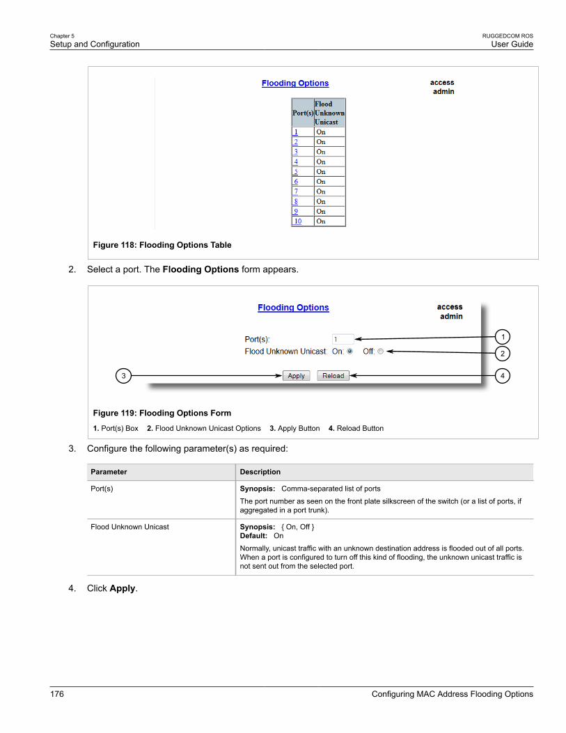
Chapter 5Setup and Configuration
RUGGEDCOM ROSUser Guide
176 Configuring MAC Address Flooding Options
Figure 118: Flooding Options Table
2. Select a port. The Flooding Options form appears.
43
2
1
Figure 119: Flooding Options Form
1. Port(s) Box 2. Flood Unknown Unicast Options 3. Apply Button 4. Reload Button
3. Configure the following parameter(s) as required:
Parameter Description
Port(s) Synopsis: Comma-separated list of ports
The port number as seen on the front plate silkscreen of the switch (or a list of ports, ifaggregated in a port trunk).
Flood Unknown Unicast Synopsis: { On, Off }Default: On
Normally, unicast traffic with an unknown destination address is flooded out of all ports.When a port is configured to turn off this kind of flooding, the unknown unicast traffic isnot sent out from the selected port.
4. Click Apply.
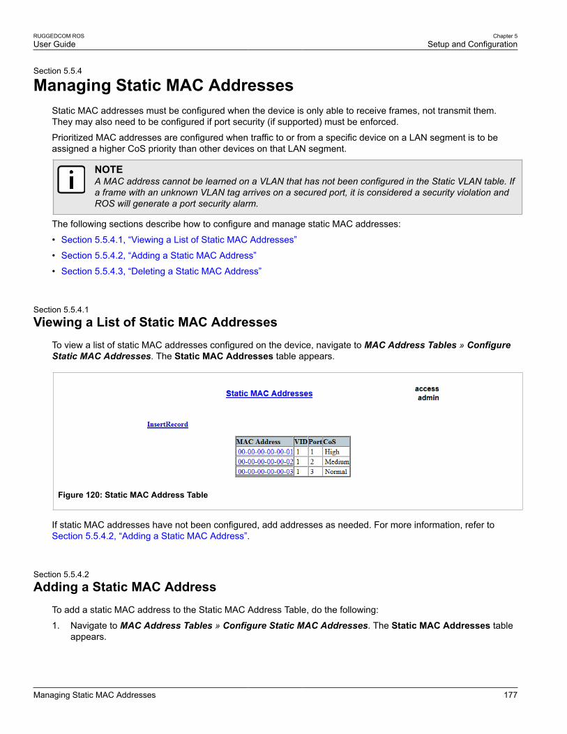
RUGGEDCOM ROSUser Guide
Chapter 5Setup and Configuration
Managing Static MAC Addresses 177
Section 5.5.4
Managing Static MAC AddressesStatic MAC addresses must be configured when the device is only able to receive frames, not transmit them.They may also need to be configured if port security (if supported) must be enforced.
Prioritized MAC addresses are configured when traffic to or from a specific device on a LAN segment is to beassigned a higher CoS priority than other devices on that LAN segment.
NOTEA MAC address cannot be learned on a VLAN that has not been configured in the Static VLAN table. Ifa frame with an unknown VLAN tag arrives on a secured port, it is considered a security violation andROS will generate a port security alarm.
The following sections describe how to configure and manage static MAC addresses:
• Section 5.5.4.1, “Viewing a List of Static MAC Addresses”
• Section 5.5.4.2, “Adding a Static MAC Address”
• Section 5.5.4.3, “Deleting a Static MAC Address”
Section 5.5.4.1
Viewing a List of Static MAC AddressesTo view a list of static MAC addresses configured on the device, navigate to MAC Address Tables » ConfigureStatic MAC Addresses. The Static MAC Addresses table appears.
Figure 120: Static MAC Address Table
If static MAC addresses have not been configured, add addresses as needed. For more information, refer toSection 5.5.4.2, “Adding a Static MAC Address”.
Section 5.5.4.2
Adding a Static MAC AddressTo add a static MAC address to the Static MAC Address Table, do the following:
1. Navigate to MAC Address Tables » Configure Static MAC Addresses. The Static MAC Addresses tableappears.

Chapter 5Setup and Configuration
RUGGEDCOM ROSUser Guide
178 Adding a Static MAC Address
1
Figure 121: Static MAC Addresses Table
1. InsertRecord
2. Click InsertRecord. The Static MAC Addresses form appears.
75
6
4
3
2
1
Figure 122: Static MAC Addresses Form
1. MAC Address Box 2. VID Box 3. Port Box 4. CoS List 5. Apply Button 6. Delete Button 7. Reload Button
3. Configure the following parameter(s) as required:
Parameter Description
MAC Address Synopsis: ##-##-##-##-##-## where ## ranges 0 to FF
A MAC address learned by the switch.
Maximum of 6 wildcard characters may be used to specify a range of MAC addressesallowed to be learned by the Port Security module (when Port Security is set to 'StaticMAC' mode). Wildcard must start from the right hand end and continuous.
Examples:
• 00-0A-DC-**-**-** means the entire MAC address space of RuggedCom.• 00-0A-DC-12-3*-** means the range 00-0A-DC-12-30-00 to 00-0A-DC-12-3F-FF.
VID Synopsis: 1 to 4094 or { ANY }Default: 1VLAN Identifier of the VLAN upon which the MAC address operates.
Option ANY allows learning a MAC address through the Port Security module on anyVLAN's that are configured on the switch.

RUGGEDCOM ROSUser Guide
Chapter 5Setup and Configuration
Deleting a Static MAC Address 179
Parameter Description
Port Synopsis: 1 to maximum port number or { Learn }Default: Learn
Enter the port number upon which the device with this address is located. The securitymode of the port being selected should not be '802.1X'.
If the port should be auto-learned, set this parameter to 'Learn'. The option 'Learn' isapplicable for Port Security in 'Static MAC' mode.
CoS Synopsis: { N/A, Normal, Medium, High, Crit }Default: N/A
Prioritizes traffic for the specified MAC address. To not prioritize traffic based on theaddress, select N/A.
4. Click Apply.
Section 5.5.4.3
Deleting a Static MAC AddressTo delete a static MAC address from the Static MAC Address Table, do the following:
1. Navigate to MAC Address Tables » Configure Static MAC Addresses. The Static MAC Addresses tableappears.
Figure 123: Static MAC Addresses Table
2. Select the MAC address from the table. The Static MAC Addresses form appears.

Chapter 5Setup and Configuration
RUGGEDCOM ROSUser Guide
180 Purging All Dynamic MAC Addresses
75
6
4
3
2
1
Figure 124: Static MAC Addresses Form
1. MAC Address Box 2. VID Box 3. Port Box 4. CoS List 5. Apply Button 6. Delete Button 7. Reload Button
3. Click Delete.
Section 5.5.5
Purging All Dynamic MAC AddressesTo purge the dynamic MAC address list of all entries, do the following:
1. Navigate to MAC Address Tables » Purge MAC Address Table. The Purge MAC Address Table formappears.
1
Figure 125: Purge MAC Address Table Form
1. Confirm Button
2. Click Confirm.
Section 5.6
Managing Time ServicesThe System Time Manager offers the following time-keeping and time synchronization features:
• Local hardware time keeping and time zone management
• SNTP (Simple Network Time Protocol) client and server

RUGGEDCOM ROSUser Guide
Chapter 5Setup and Configuration
Configuring the Time and Date 181
The following sections describe how to configure time-keeping and time synchronization through the SystemTime Manager:
• Section 5.6.1, “Configuring the Time and Date”
• Section 5.6.2, “Configuring NTP”
Section 5.6.1
Configuring the Time and DateTo set the time, date and other time-keeping related parameters, do the following:
1. Navigate to Administration » System Time Manager » Configure Time and Date. The Time and Dateform appears.
76
5
4
3
2
1
Figure 126: Time and Date Form
1. Time 2. Date 3. Time Zone 4. DST Offset 5. DST Rule 6. Apply Button 7. Reload Button
2. Configure the following parameter(s) as required:
Parameter Description
Time Synopsis: HH:MM:SS
This parameter allows for both the viewing and setting of the local time.
Date Synopsis: MMM DD, YYYY
This parameter allows for both the viewing and setting of the local date.
Time Zone Synopsis: { UTC-12:00 (Eniwetok, Kwajalein), UTC-11:00 (Midway Island, Samoa),UTC-10:00 (Hawaii), UTC-9:00 (Alaska), UTC-8:00 (Los Angeles, Vancouver),UTC-7:00 (Calgary, Denver), UTC-6:00 (Chicago, Mexico City), UTC-5:00 (New York,Toronto), UTC-4:30 (Caracas), UTC-4:00 (Santiago), UTC-3:30 (Newfoundland),UTC-3:00 (Brasilia, Buenos Aires), UTC-2:00 (Mid Atlantic), UTC-1:00 (Azores),UTC-0:00 (Lisbon, London), UTC+1:00 (Berlin, Paris, Rome), UTC+2:00 (Athens, Cairo,Helsinki), ... }Default: UTC-5:00 (New York, Toronto)
This setting allows for the conversion of UTC (Universal Coordinated Time) to local time.
DST Offset Synopsis: HH:MM:SSDefault: 00:00:00

Chapter 5Setup and Configuration
RUGGEDCOM ROSUser Guide
182 Configuring NTP
Parameter Description
This parameter specifies the amount of time to be shifted forward/backward when DSTbegins and ends. For example for most part of USA and Canada, DST time shift is 1hour (01:00:00) forward when DST begins and 1 hour backward when DST ends.
DST Rule Synopsis: mm.n.d/HH:MM:SS mm.n.d/HH:MM:SS
This parameter specifies a rule for time and date when the transition between Standardand Daylight Saving Time occurs.
• mm - Month of the year (01 - January, 12 - December)• n - nth d-day in the month (1 - 1st d-day, 5 - 5th/last d-day)• d - day of the week (0 - Sunday, 6 - Saturday)• HH - hour of the day (0 - 24)• MM - minute of the hour (0 - 59)• SS - second of the minute (0 - 59)
Example: The following rule applies in most part of USA and Canada:
03.2.0/02:00:00 11.1.0/02:00:00
DST begins on March's 2nd Sunday at 2:00am.
DST ends on November's 1st Sunday at 2:00am.
Section 5.6.2
Configuring NTPROS may be configured to refer periodically to a specified NTP server to correct any accumulated drift in the on-board clock. ROS will also serve time via the Simple Network Time Protocol (SNTP) to hosts that request it.
Two NTP servers (primary and backup) may be configured for the device. The primary server is contacted first foreach attempt to update the system time. If the primary server fails to respond, the backup server is contacted. Ifeither the primary or backup server fails to respond, an alarm is raised.
To configure either the primary or backup NTP server, do the following:
1. Navigate to Administration » System Time Manager » Configure NTP Server. The NTP Server tableappears.
Figure 127: NTP Server Table
2. Select either Primary or Backup. The NTP Server form appears.

RUGGEDCOM ROSUser Guide
Chapter 5Setup and Configuration
Managing SNMP 183
54
2
3
1
Figure 128: NTP Server Form
1. Server Box 2. IP Address Box 3. Update Period Box 4. Apply Button 5. Reload Button
3. Configure the following parameter(s) as required:
Parameter Description
Server Synopsis: Any 8 charactersDefault: Primary
This field tells whether this configuration is for a Primary or a Backup Server.
IP Address Synopsis: ###.###.###.### where ### ranges from 0 to 255
The Server IP Address.
Update Period Synopsis: 1 to 1440 minDefault: 60 min
Determines how frequently the (S)NTP server is polled for a time update.If the servercannot be reached in three attempts that are made at one minute intervals an alarm isgenerated.
4. Click Apply.
Section 5.7
Managing SNMPROS supports versions 1, 2 and 3 of the Simple Network Management Protocol (SNMP), otherwise referred toas SNMPv1, SNMPv2c and SNMPv3 respectively. SNMPv3 provides secure access to the devices through acombination of authentication and packet encryption over the network. Security features for this protocol include:
Feature Description
Message Integrity Makes sure that a packet has not been tampered with in-transit.
Authentication Determines if the message is from a valid source.
Encryption Encrypts the contents of a packet to prevent it from being seen by an unauthorized source.
SNMPv3 provides security models and security levels. A security model is an authentication strategy setup fora user and the group in which the user resides. A security level is a permitted level of security within a securitymodel. A combination of a security model and level will determine which security mechanism is employed whenhandling an SNMP packet.

Chapter 5Setup and Configuration
RUGGEDCOM ROSUser Guide
184 Managing SNMP Users
Before configuring SNMPv3, note the following:
• Each user belongs to a group
• A group defines the access policy for a set of users
• An access policy defines what SNMP objects can be accessed for (i.e. reading, writing and creatingnotifications)
• A group determines the list of notifications its users can receive
• A group also defines the security model and security level for its users
For SNMPv1 and SNMPv2c, a community string can be configured. The string is mapped to the group andaccess level with a security name, which is configured as User Name.
The following sections describe how to setup and manage SNMP on the device:
• Section 5.7.1, “Managing SNMP Users”
• Section 5.7.2, “Managing Security-to-Group Mapping”
• Section 5.7.3, “Managing SNMP Groups”
Section 5.7.1
Managing SNMP UsersThe following sections describe how to configure and manage SNMP users, refer to the following:
• Section 5.7.1.1, “Viewing a List of SNMP Users”
• Section 5.7.1.2, “Adding an SNMP User”
• Section 5.7.1.3, “Deleting an SNMP User”
Section 5.7.1.1
Viewing a List of SNMP UsersTo view a list of SNMP users configured on the device, navigate to Administration » Configure SNMP »Configure SNMP Users. The SNMP Users table appears.
Figure 129: SNMP Users Table
If users have not been configured, add users as needed. For more information, refer to Section 5.7.1.2, “Addingan SNMP User”.
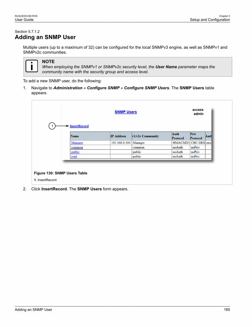
RUGGEDCOM ROSUser Guide
Chapter 5Setup and Configuration
Adding an SNMP User 185
Section 5.7.1.2
Adding an SNMP UserMultiple users (up to a maximum of 32) can be configured for the local SNMPv3 engine, as well as SNMPv1 andSNMPv2c communities.
NOTEWhen employing the SNMPv1 or SNMPv2c security level, the User Name parameter maps thecommunity name with the security group and access level.
To add a new SNMP user, do the following:
1. Navigate to Administration » Configure SNMP » Configure SNMP Users. The SNMP Users tableappears.
1
Figure 130: SNMP Users Table
1. InsertRecord
2. Click InsertRecord. The SNMP Users form appears.
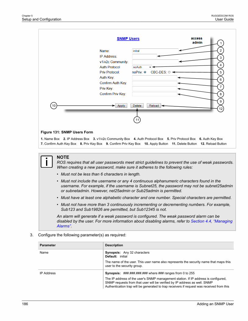
Chapter 5Setup and Configuration
RUGGEDCOM ROSUser Guide
186 Adding an SNMP User
1210
11
9
8
7
6
5
4
3
2
1
Figure 131: SNMP Users Form
1. Name Box 2. IP Address Box 3. v1/v2c Community Box 4. Auth Protocol Box 5. Priv Protocol Box 6. Auth Key Box 7. Confirm Auth Key Box 8. Priv Key Box 9. Confirm Priv Key Box 10. Apply Button 11. Delete Button 12. Reload Button
NOTEROS requires that all user passwords meet strict guidelines to prevent the use of weak passwords.When creating a new password, make sure it adheres to the following rules:
• Must not be less than 6 characters in length.
• Must not include the username or any 4 continuous alphanumeric characters found in theusername. For example, if the username is Subnet25, the password may not be subnet25adminor subnetadmin. However, net25admin or Sub25admin is permitted.
• Must have at least one alphabetic character and one number. Special characters are permitted.
• Must not have more than 3 continuously incrementing or decrementing numbers. For example,Sub123 and Sub19826 are permitted, but Sub12345 is not.
An alarm will generate if a weak password is configured. The weak password alarm can bedisabled by the user. For more information about disabling alarms, refer to Section 4.4, “ManagingAlarms”.
3. Configure the following parameter(s) as required:
Parameter Description
Name Synopsis: Any 32 charactersDefault: initial
The name of the user. This user name also represents the security name that maps thisuser to the security group.
IP Address Synopsis: ###.###.###.### where ### ranges from 0 to 255
The IP address of the user's SNMP management station. If IP address is configured,SNMP requests from that user will be verified by IP address as well. SNMPAuthentication trap will be generated to trap receivers if request was received from this
RUGGEDCOM ROSUser Guide
Chapter 5Setup and Configuration
Deleting an SNMP User 187
Parameter Description
user, but from any other IP address.If IP address is empty, traps can not be generated tothis user, but SNMP requests will be served for this user from any IP address.
v1/v2c Community Synopsis: Any 32 characters
The community string which is mapped by this user/security name to the security groupif security model is SNMPv1 or SNMPv2c. If this string is left empty, it will be assumed tobe equal to the same as user name.
Auth Protocol Synopsis: { noAuth, HMACMD5 }Default: noAuth
An indication of whether messages sent on behalf of this user to/from SNMP engine,can be authenticated, and if so, the type of authentication protocol which is used.
Priv Protocol Synopsis: { noPriv, CBC-DES }Default: noPriv
An Indication of whether messages sent on behalf of this user to/from SNMP engine canbe protected from disclosure, and if so, the type of privacy protocol which is used.
Auth Key Synopsis: 31 character ASCII string
The secret authentication key (password) that must be shared with SNMP client. If thekey is not an emtpy string, it must be at least 6 characters long.
Confirm Auth Key Synopsis: 31 character ASCII string
The secret authentication key (password) that must be shared with SNMP client. If thekey is not an emtpy string, it must be at least 6 characters long.
Priv Key Synopsis: 31 character ASCII string
The secret encription key (password) that must be shared with SNMP client. If the key isnot an emtpy string, it must be at least 6 characters long.
Confirm Priv Key Synopsis: 31 character ASCII string
The secret encription key (password) that must be shared with SNMP client. If the key isnot an emtpy string, it must be at least 6 characters long.
4. Click Apply.
Section 5.7.1.3
Deleting an SNMP UserTo delete an SNMP user, do the following:
1. Navigate to Administration » Configure SNMP » Configure SNMP Users. The SNMP Users tableappears.

Chapter 5Setup and Configuration
RUGGEDCOM ROSUser Guide
188 Managing Security-to-Group Mapping
Figure 132: SNMP Users Table
2. Select the user from the table. The SNMP Users form appears.
1210
11
9
8
7
6
5
4
3
2
1
Figure 133: SNMP Users Form
1. Name Box 2. IP Address Box 3. v1/v2c Community Box 4. Auth Protocol Box 5. Priv Protocol Box 6. Auth Key Box 7. Confirm Auth Key Box 8. Priv Key Box 9. Confirm Priv Key Box 10. Apply Button 11. Delete Button 12. Reload Button
3. Click Delete.
Section 5.7.2
Managing Security-to-Group MappingThe following sections describe how to configure and manage security-to-group maps, refer to the following:
• Section 5.7.2.1, “Viewing a List of Security-to-Group Maps”
• Section 5.7.2.2, “Adding a Security-to-Group Map”

RUGGEDCOM ROSUser Guide
Chapter 5Setup and Configuration
Viewing a List of Security-to-Group Maps 189
• Section 5.7.2.3, “Deleting a Security-to-Group Map”
Section 5.7.2.1
Viewing a List of Security-to-Group MapsTo view a list of security-to-group maps configured on the device, navigate to Administration » ConfigureSNMP » Configure SNMP Security to Group Maps. The SNMP Security to Group Maps table appears.
Figure 134: SNMP Security to Group Maps Table
If security-to-group maps have not been configured, add maps as needed. For more information, refer toSection 5.7.2.2, “Adding a Security-to-Group Map”.
Section 5.7.2.2
Adding a Security-to-Group MapMultiple combinations of security models and groups can be mapped (up to a maximum of 32) for SNMP.
To add a security-to-group map, do the following:
1. Navigate to Administration » Configure SNMP » Configure SNMP Security to Group Maps. The SNMPSecurity to Group Maps table appears.
1
Figure 135: SNMP Security to Group Maps Table1. InsertRecord
2. Click InsertRecord. The SNMP Security to Group Maps form appears.

Chapter 5Setup and Configuration
RUGGEDCOM ROSUser Guide
190 Deleting a Security-to-Group Map
64
5
3
2
1
Figure 136: SNMP Security to Group Maps Form
1. Security Model Box 2. Name Box 3. Group Box 4. Apply Button 5. Delete Button 6. Reload Button
3. Configure the following parameter(s) as required:
Parameter Description
SecurityModel Synopsis: { snmpV1, snmpV2c, snmpV3 }Default: snmpV3
The Security Model that provides the name referenced in this table.
Name Synopsis: Any 32 characters
The user name which is mapped by this entry to the specified group name.
Group Synopsis: Any 32 characters
The group name to which the security model and name belong. This name is used as anindex to the SNMPv3 VACM Access Table.
4. Click Apply.
Section 5.7.2.3
Deleting a Security-to-Group MapTo delete a security-to-group map, do the following:
1. Navigate to Administration » Configure SNMP » Configure SNMP Security to Group Maps. The SNMPSecurity to Group Maps table appears.

RUGGEDCOM ROSUser Guide
Chapter 5Setup and Configuration
Managing SNMP Groups 191
Figure 137: SNMP Security to Group Maps Table
2. Select the map from the table. The SNMP Security to Group Maps form appears.
64
5
3
2
1
Figure 138: SNMP Security to Group Maps Form
1. Security Model Box 2. Name Box 3. Group Box 4. Apply Button 5. Delete Button 6. Reload Button
3. Click Delete.
Section 5.7.3
Managing SNMP GroupsMultiple SNMP groups (up to a maximum of 32) can be configured to have access to SNMP.
The following sections describe how to configure and manage SNMP groups on the device:
• Section 5.7.3.1, “Viewing a List of SNMP Groups”
• Section 5.7.3.2, “Adding an SNMP Group”
• Section 5.7.3.3, “Deleting an SNMP Group”

Chapter 5Setup and Configuration
RUGGEDCOM ROSUser Guide
192 Viewing a List of SNMP Groups
Section 5.7.3.1
Viewing a List of SNMP GroupsTo view a list of SNMP groups configured on the device, navigate to Administration » Configure SNMP »Configure SNMP Access. The SNMP Access table appears.
Figure 139: SNMP Access Table
If SNMP groups have not been configured, add groups as needed. For more information, refer to Section 5.7.3.2,“Adding an SNMP Group”.
Section 5.7.3.2
Adding an SNMP GroupTo add an SNMP group, do the following:
1. Navigate to Administration » Configure SNMP » Configure SNMP Access. The SNMP Access tableappears.
1
Figure 140: SNMP Access Table
1. InsertRecord
2. Click InsertRecord. The SNMP Access form appears.

RUGGEDCOM ROSUser Guide
Chapter 5Setup and Configuration
Adding an SNMP Group 193
97
8
6
5
4
3
2
1
Figure 141: SNMP Access Form
1. Group Box 2. Security Model Box 3. Security Level Box 4. ReadViewName Box 5. WriteViewName Box 6. NotifyViewName Box 7. Apply Button 8. Delete Button 9. Reload Button
3. Configure the following parameter(s) as required:
Parameter Description
Group Synopsis: Any 32 characters
The group name to which the security model and name belong. This name is used as anindex to the SNMPv3 VACM Access Table.
SecurityModel Synopsis: { snmpV1, snmpV2c, snmpV3 }Default: snmpV3
In order to gain the access rights allowed by this entry, configured security model mustbe in use.
SecurityLevel Synopsis: { noAuthNoPriv, authNoPriv, authPriv }Default: noAuthNoPriv
The minimum level of security reqwuired in order to gain the access rights allowed bythis entry. A security level of noAuthNoPriv is less than authNoPriv, which is less thanauthPriv.
ReadViewName Synopsis: { noView, V1Mib, allOfMib }Default: noView
This parameter identifies the MIB tree(s) to which this entry authorizes read access. Ifthe value is noView, then no read access is granted.
WriteViewName Synopsis: { noView, V1Mib, allOfMib }Default: noView
This parameter identifies the MIB tree(s) to which this entry authorizes write access. Ifthe value is noView, then no write access is granted.
NotifyViewName Synopsis: { noView, V1Mib, allOfMib }Default: noView
This parameter identifies the MIB tree(s) to which this entry authorizes access fornotifications. If the value is noView, then no access for notifications is granted.
4. Click Apply.

Chapter 5Setup and Configuration
RUGGEDCOM ROSUser Guide
194 Deleting an SNMP Group
Section 5.7.3.3
Deleting an SNMP GroupTo delete an SNMP group, do the following:
1. Navigate to Administration » Configure SNMP » Configure SNMP Access. The SNMP Access tableappears.
Figure 142: SNMP Access Table
2. Select the group from the table. The SNMP Access form appears.
97
8
6
5
4
3
2
1
Figure 143: SNMP Access Form
1. Group Box 2. Security Model Box 3. Security Level Box 4. ReadViewName Box 5. WriteViewName Box 6. NotifyViewName Box 7. Apply Button 8. Delete Button 9. Reload Button
3. Click Delete.
Section 5.8
Managing Network DiscoveryROS supports the Link Layer Discovery Protocol (LLDP) and RUGGEDCOM Discovery Protocol (RCDP), bothLayer 2 protocols for automated network discovery.
The following sections describe how to configure and manage network discovery, refer to the following:
• Section 5.8.1, “Network Discovery Concepts”

RUGGEDCOM ROSUser Guide
Chapter 5Setup and Configuration
Network Discovery Concepts 195
• Section 5.8.2, “Configuring LLDP Globally”
• Section 5.8.3, “Configuring LLDP for an Ethernet Port”
• Section 5.8.4, “Enabling/Disabling RCDP”
• Section 5.8.5, “Viewing Global Statistics and Advertised System Information”
• Section 5.8.6, “Viewing Statistics for LLDP Neighbors”
• Section 5.8.7, “Viewing Statistics for LLDP Ports”
Section 5.8.1
Network Discovery ConceptsThe following sections describe some of the concepts important to the implementation of network discovery inROS:
• Section 5.8.1.1, “Link Layer Discovery Protocol (LLDP)”
• Section 5.8.1.2, “RUGGEDCOM Discovery Protocol (RCDP)”
Section 5.8.1.1
Link Layer Discovery Protocol (LLDP)LLDP is an IEEE standard protocol, IEEE 802.11AB, that allows a networked device to advertise its own basicnetworking capabilities and configuration.
LLDP allows a networked device to discover its neighbors across connected network links using a standardmechanism. Devices that support LLDP are able to advertise information about themselves, including theircapabilities, configuration, interconnections, and identifying information.
LLDP agent operation is typically implemented as two modules: the LLDP transmit module and LLDP receivemodule. The LLDP transmit module, when enabled, sends the local device’s information at regular intervals, inIEEE 802.1AB standard format. Whenever the transmit module is disabled, it transmits an LLDPDU (LLDP dataunit) with a time-to-live (TTL) type-length-value (TLV) containing 0 in the information field. This enables remotedevices to remove the information associated with the local device in their databases. The LLDP receive module,when enabled, receives remote devices’ information and updates its LLDP database of remote systems. Whennew or updated information is received, the receive module initiates a timer for the valid duration indicated bythe TTL TLV in the received LLDPDU. A remote system’s information is removed from the database when anLLDPDU is received from it with TTL TLV containing 0 in its information field.
NOTELLDP is implemented to keep a record of only one device per Ethernet port. Therefore, if there aremultiple devices sending LLDP information to a switch port on which LLDP is enabled, informationabout the neighbor on that port will change constantly.
Section 5.8.1.2
RUGGEDCOM Discovery Protocol (RCDP)RUGGEDCOM Discovery Protocol (RCDP) supports the deployment of ROS -based devices that have not beenconfigured since leaving the factory. ROS devices that have not been configured all have the default IP (Layer 3)address. Connecting more than one of them on a Layer 2 network means that one cannot use standard IP-based

Chapter 5Setup and Configuration
RUGGEDCOM ROSUser Guide
196 Configuring LLDP Globally
configuration tools to configure them. The behavior of IP-based mechanisms such as the web interface, SSH,telnet, or SNMP will all be undefined.
Since RCDP operates at Layer 2, it can be used to reliably and unambiguously address multiple devices eventhough they may share the same IP configuration.
Siemens 's RUGGEDCOM Explorer is a lightweight, standalone Windows application that supports RCDP. It iscapable of discovering, identifying and performing basic configuration of ROS-based devices via RCDP. Thefeatures supported by RCDP include:
• Discovery of ROS-based devices over a Layer 2 network.
• Retrieval of basic network configuration, ROS version, order code, and serial number.
• Control of device LEDs for easy physical identification.
• Configuration of basic identification, networking, and authentication parameters.
For security reasons, RUGGEDCOM Explorer will attempt to disable RCDP on all devices when Explorer is shutdown. If RUGGEDCOM Explorer is unable to disable RCDP on a device, ROS will automatically disable RCDPafter approximately one hour of inactivity.
NOTERCDP is not compatible with VLAN-based network configurations. For correct operation ofRUGGEDCOM Explorer, no VLANs (tagged or untagged) must be configured. All VLAN configurationitems must be at their default settings.
NOTEROS responds to RCDP requests only. It does not under any circumstances initiate any RCDP-basedcommunication.
Section 5.8.2
Configuring LLDP GloballyTo configure the global settings for LLDP, do the following:
1. Navigate to Network Discovery » Link Layer Discovery Protocol » Configure Global LLDP Parameters.The Global LLDP Parameters form appears.

RUGGEDCOM ROSUser Guide
Chapter 5Setup and Configuration
Configuring LLDP Globally 197
6
5
4
3
2
1
7
Figure 144: Global LLDP Parameters Form
1. State Options 2. Tx Interval Box 3. Tx Hold Box 4. Reinit Delay Box 5. Tx Delay Box 6. Apply Button 7. Reload Button
2. Configure the following parameter(s) as required:
Parameter Description
State Synopsis: { Disabled, Enabled }Default: Enabled
Enables LLDP protocol. Note that LLDP is enabled on a port when LLDP is enabledglobally and along with enabling per port setting in Port LLDP Parameters menu.
Tx Interval Synopsis: 5 to 32768 sDefault: 30 s
The interval at which LLDP frames are transmitted on behalf of this LLDP agent.
Tx Hold Synopsis: 2 to 10Default: 4The multiplier of the Tx Interval parameter that determines the actual time-to-live (TTL)value used in a LLDPDU. The actual TTL value can be expressed by the followingformula:
TTL = MIN(65535, (Tx Interval * Tx Hold))
Reinit Delay Synopsis: 1 to 10 sDefault: 2 s
The delay in seconds from when the value of Admin Status parameter of a particularport becomes 'Disbled' until re-initialization will be lattempted.
Tx Delay Synopsis: 1 to 8192 sDefault: 2 s
The delay in seconds between successive LLDP frame transmissions initiated by valueor status changed. The recommended value is set by the following formula:
1 <= txDelay <= (0.25 * Tx Interval)
3. Click Apply.

Chapter 5Setup and Configuration
RUGGEDCOM ROSUser Guide
198 Configuring LLDP for an Ethernet Port
Section 5.8.3
Configuring LLDP for an Ethernet PortTo configure LLDP for a specific Ethernet Port, do the following:
1. Navigate to Network Discovery » Link Layer Discovery Protocol » Configure Port LLDP Parameters.The Port LLDP Parameters table appears.
Figure 145: Port LLDP Parameters Table
2. Select a port. The Port LLDP Parameters form appears.
54
3
2
1
Figure 146: Port LLDP Parameters Form
1. Port Box 2. Admin Status List 3. Notifications Options 4. Apply Button 5. Reload Button
3. Configure the following parameter(s) as required:
Parameter Description
Port Synopsis: 1 to maximum port numberDefault: 1The port number as seen on the front plate silkscreen of the switch.
Admin Status Synopsis: { rxTx, txOnly, rxOnly, Disabled }Default: rxTx
rxTx: the local LLDP agent can both transmit and receive LLDP frames through the port.
txOnly: the local LLDP agent can only transmit LLDP frames.

RUGGEDCOM ROSUser Guide
Chapter 5Setup and Configuration
Enabling/Disabling RCDP 199
Parameter Description
rxOnly: the local LLDP agent can only receive LLDP frames.
disabled: the local LLDP agent can neither transmit or receive LLDP frames.
Notifications Synopsis: { Disabled, Enabled }Default: Disabled
Disabling notifications will prevent sending notifications and generating alarms forparticular port from the LLDP agent.
4. Click Apply.
Section 5.8.4
Enabling/Disabling RCDPROS supports the RUGGEDCOM Discovery Protocol (RCDP). RCDP supports the deployment of ROS -baseddevices that have not been configured since leaving the factory. ROS devices that have not been configured allhave the default IP (Layer 3) address. Connecting more than one of them on a Layer 2 network means that onecannot use standard IP-based configuration tools to configure them. The behavior of IP-based mechanisms suchas the web interface, SSH, telnet, or SNMP will all be undefined.
Since RCDP operates at Layer 2, it can be used to reliably and unambiguously address multiple devices eventhough they may share the same IP configuration.
Siemens 's RUGGEDCOM Explorer is a lightweight, standalone Windows application that supports RCDP. It iscapable of discovering, identifying and performing basic configuration of ROS-based devices via RCDP. Thefeatures supported by RCDP include:
• Discovery of ROS-based devices over a Layer 2 network.
• Retrieval of basic network configuration, ROS version, order code, and serial number.
• Control of device LEDs for easy physical identification.
• Configuration of basic identification, networking, and authentication parameters.
For security reasons, RUGGEDCOM Explorer will attempt to disable RCDP on all devices when Explorer is shutdown. If RUGGEDCOM Explorer is unable to disable RCDP on a device, ROS will automatically disable RCDPafter approximately one hour of inactivity.
NOTERCDP is not compatible with VLAN-based network configurations. For correct operation ofRUGGEDCOM Explorer, no VLANs (tagged or untagged) must be configured. All VLAN configurationitems must be at their default settings.
NOTEROS responds to RCDP requests only. It does not under any circumstances initiate any RCDP-basedcommunication.
To enable or disable RCDP, do the following:
1. Navigate to Network Discovery » Configure RCDP Parameters. The RCDP Parameters form appears.

Chapter 5Setup and Configuration
RUGGEDCOM ROSUser Guide
200Viewing Global Statistics and Advertised System
Information
32
1
Figure 147: RCDP Parameters Form
1. RCDP Discovery Options 2. Apply Button 3. Reload Button
2. Select Enabled to enable RCDP, or select Disabled to disable RCDP.
3. Click Apply.
Section 5.8.5
Viewing Global Statistics and Advertised System InformationTo view global statistics for LLDP and the system information that is advertised to neighbors, navigate to NetworkDiscovery » Link Layer Discovery Protocol » View LLDP Global Remote Statistics. The LLDP GlobalRemote Statistics form appears.
1
5
2
3
4
Figure 148: LLDP Global Remote Statistics Form
1. Inserts Box 2. Deletes Box 3. Drops Box 4. Ageouts Box 5. Reload Button
This form displays the following information:
Parameter Description
Inserts Synopsis: 0 to 4294967295
A number of times the entry in LLDP Neighbor Information Table was inserted.
Deletes Synopsis: 0 to 4294967295
A number of times the entry in LLDP Neighbor Information Table was deleted.
Drops Synopsis: 0 to 4294967295

RUGGEDCOM ROSUser Guide
Chapter 5Setup and Configuration
Viewing Statistics for LLDP Neighbors 201
Parameter Description
A number of times an entry was deleted from LLDP Neighbor Information Table because theinformation timeliness interval has expired.
Ageouts Synopsis: 0 to 4294967295
A counter of all TLVs discarded.
Section 5.8.6
Viewing Statistics for LLDP NeighborsTo view statistics for LLDP neighbors, navigate to Network Discovery » Link Layer Discovery Protocol » ViewLLDP Neighbor Information. The LLDP Neighbor Information table appears.
1
6
2
3
4
5
Figure 149: LLDP Neighbor Information Table
1. Port Box 2. ChassisId Box 3. PortId Box 4. SysName Box 5. SysDesc Box 6. Reload Button
This form displays the following information:
Parameter Description
Port Synopsis: 1 to maximum port number
The local port associated with this entry.
ChassisId Synopsis: Any 45 characters
Chassis Id information received from remote LLDP agent.
PortId Synopsis: Any 45 characters
Port Id information received from remote LLDP agent.
SysName Synopsis: Any 45 characters
System Name information received from remote LLDP agent.
SysDesc Synopsis: Any 45 characters
System Descriptor information received from remote LLDP agent.

Chapter 5Setup and Configuration
RUGGEDCOM ROSUser Guide
202 Viewing Statistics for LLDP Ports
Section 5.8.7
Viewing Statistics for LLDP PortsTo view statistics for LLDP ports, navigate to Network Discovery » Link Layer Discovery Protocol » ViewLLDP Statistics. The LLDP Statistics table appears.
Figure 150: LLDP Statistics Table
This table displays the following information:
Parameter Description
Port Synopsis: 1 to maximum port number
The port number as seen on the front plate silkscreen of the switch.
FrmDrop Synopsis: 0 to 4294967295
A counter of all LLDP frames discarded.
ErrFrm Synopsis: 0 to 4294967295
A counter of all LLDPDUs received with detectable errors.
FrmIn Synopsis: 0 to 4294967295
A counter of all LLDPDUs received.
FrmOut Synopsis: 0 to 4294967295
A counter of all LLDPDUs transmitted.
Ageouts Synopsis: 0 to 4294967295
A counter of the times that a neighbor's information has been deleted from the LLDP remotesystem MIB because the txinfoTTL timer has expired.
TLVsDrop Synopsis: 0 to 4294967295
A counter of all TLVs discarded.
TLVsUnknown Synopsis: 0 to 4294967295
A counter of all TLVs received on the port that are not recognized by the LLDP local agent.

RUGGEDCOM ROSUser Guide
Chapter 5Setup and Configuration
Managing Multicast Filtering 203
Section 5.9
Managing Multicast FilteringMulticast traffic can be filtered using either static multicast groups, IGMP (Internet Group Management Protocol)snooping, or GMRP (GARP Multicast Registration Protocol).
The following sections describe how to configure and manage multicast filtering:
• Section 5.9.1, “Multicast Filtering Concepts”
• Section 5.9.1.2, “GMRP (GARP Multicast Registration Protocol)”
• Section 5.9.2, “Viewing a List of IP Multicast Groups”
• Section 5.9.3, “Viewing a Summary of Multicast Groups”
• Section 5.9.4, “Configuring IGMP”
• Section 5.9.5, “Configuring GMRP Globally”
• Section 5.9.6, “Configuring GMRP for Specific Ethernet Ports”
• Section 5.9.7, “Managing Static Multicast Groups”
Section 5.9.1
Multicast Filtering ConceptsThe following sections describe some of the concepts important to the implementation of multicast filtering inROS:
• Section 5.9.1.1, “IGMP”
• Section 5.9.1.2, “GMRP (GARP Multicast Registration Protocol)”
Section 5.9.1.1
IGMPIGMP is used by IP hosts to report their host group memberships with multicast routers. As hosts join and leavespecific multicast groups, streams of traffic are directed to or withheld from that host.
The IGMP protocol operates between multicast routers and IP hosts. When an unmanaged switch is placedbetween multicast routers and their hosts, the multicast streams will be distributed to all ports.This may introducesignificant traffic onto ports that do not require it and receive no benefit from it.
IGMP Snooping, when enabled, will act on IGMP messages sent from the router and the host, restricting trafficstreams to the appropriate LAN segments.
Example: IGMP In OperationThe following network diagram provides a simple example of the use of IGMP.
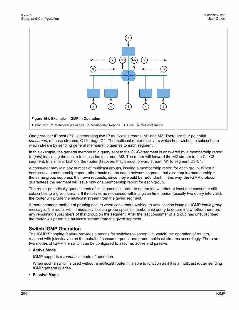
Chapter 5Setup and Configuration
RUGGEDCOM ROSUser Guide
204 IGMP
3
2
3
2
1
4
M2M1
4544
Figure 151: Example – IGMP In Operation
1. Producer 2. Membership Queries 3. Membership Reports 4. Host 5. Multicast Router
One producer IP host (P1) is generating two IP multicast streams, M1 and M2. There are four potentialconsumers of these streams, C1 through C4. The multicast router discovers which host wishes to subscribe towhich stream by sending general membership queries to each segment.
In this example, the general membership query sent to the C1-C2 segment is answered by a membership report(or join) indicating the desire to subscribe to stream M2. The router will forward the M2 stream to the C1-C2segment. In a similar fashion, the router discovers that it must forward stream M1 to segment C3-C4.
A consumer may join any number of multicast groups, issuing a membership report for each group. When ahost issues a membership report, other hosts on the same network segment that also require membership tothe same group suppress their own requests, since they would be redundant. In this way, the IGMP protocolguarantees the segment will issue only one membership report for each group.
The router periodically queries each of its segments in order to determine whether at least one consumer stillsubscribes to a given stream. If it receives no responses within a given time period (usually two query intervals),the router will prune the multicast stream from the given segment.
A more common method of pruning occurs when consumers wishing to unsubscribe issue an IGMP leave groupmessage. The router will immediately issue a group-specific membership query to determine whether there areany remaining subscribers of that group on the segment. After the last consumer of a group has unsubscribed,the router will prune the multicast stream from the given segment.
Switch IGMP OperationThe IGMP Snooping feature provides a means for switches to snoop (i.e. watch) the operation of routers,respond with joins/leaves on the behalf of consumer ports, and prune multicast streams accordingly. There aretwo modes of IGMP the switch can be configured to assume: active and passive.
• Active ModeIGMP supports a routerless mode of operation.
When such a switch is used without a multicast router, it is able to function as if it is a multicast router sendingIGMP general queries.
• Passive Mode

RUGGEDCOM ROSUser Guide
Chapter 5Setup and Configuration
IGMP 205
When such a switch is used in a network with a multicast router, it can be configured to run Passive IGMP. Thismode prevents the switch from sending the queries that can confuse the router causing it to stop issuing IGMPqueries.
NOTEA switch running in passive mode requires the presence of a multicast router or it will be unable toforward multicast streams at all if no multicast routers are present.
NOTEAt least one IGMP Snooping switch must be in active mode to make IGMP functional.
IGMP Snooping RulesIGMP Snooping adheres to the following rules:
• When a multicast source starts multicasting, the traffic stream will be immediately blocked on segments fromwhich joins have not been received.
• Unless configured otherwise, the switch will forward all multicast traffic to the ports where multicast routers areattached.
• Packets with a destination IP multicast address in the 224.0.0.X range that are not IGMP are always forwardedto all ports. This behavior is based on the fact that many systems do not send membership reports for IPmulticast addresses in this range while still listening to such packets.
• The switch implements proxy-reporting (i.e. membership reports received from downstream are summarizedand used by the switch to issue its own reports).
• The switch will only send IGMP membership reports out of those ports where multicast routers are attached,as sending membership reports to hosts could result in unintentionally preventing a host from joining a specificgroup.
• Multicast routers use IGMP to elect a master router known as the querier. The querier is the router with thelowest IP address. All other routers become non-queriers, participating only in forwarding multicast traffic.Switches running in active mode participate in the querier election the same as multicast routers.
• When the querier election process is complete, the switch simply relays IGMP queries received from thequerier.
• When sending IGMP packets, the switch uses its own IP address, if it has one, for the VLAN on which packetsare sent, or an address of 0.0.0.0, if it does not have an assigned IP address.
NOTEIGMP Snooping switches perform multicast pruning using a multicast frames’ destination MACmulticast address, which depends on the group IP multicast address. IP address W.X.Y.Z correspondsto MAC address 01-00-5E-XX-YY-ZZ where XX is the lower 7 bits of X, and YY and ZZ are simply Yand Z coded in hexadecimal.
One can note that IP multicast addresses, such as 224.1.1.1 and 225.1.1.1, will both map onto thesame MAC address 01-00-5E-01-01-01. This is a problem for which the IETF Network Working Groupcurrently has offered no solution. Users are advised to be aware of and avoid this problem.
IGMP and RSTPAn RSTP change of topology can render the routes selected to carry multicast traffic as incorrect. This results inlost multicast traffic.
If RSTP detects a change in the network topology, IGMP will take some actions to avoid the loss of multicastconnectivity and reduce network convergence time:
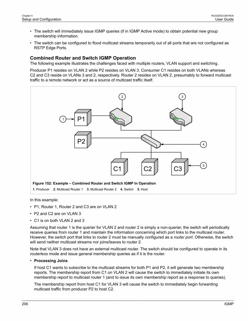
Chapter 5Setup and Configuration
RUGGEDCOM ROSUser Guide
206 IGMP
• The switch will immediately issue IGMP queries (if in IGMP Active mode) to obtain potential new groupmembership information.
• The switch can be configured to flood multicast streams temporarily out of all ports that are not configured asRSTP Edge Ports.
Combined Router and Switch IGMP OperationThe following example illustrates the challenges faced with multiple routers, VLAN support and switching.
Producer P1 resides on VLAN 2 while P2 resides on VLAN 3. Consumer C1 resides on both VLANs whereasC2 and C3 reside on VLANs 3 and 2, respectively. Router 2 resides on VLAN 2, presumably to forward multicasttraffic to a remote network or act as a source of multicast traffic itself.
P1
C1
1
P2
C2 C3
4
5
2 3
Figure 152: Example – Combined Router and Switch IGMP In Operation1. Producer 2. Multicast Router 1 3. Multicast Router 2 4. Switch 5. Host
In this example:
• P1, Router 1, Router 2 and C3 are on VLAN 2
• P2 and C2 are on VLAN 3
• C1 is on both VLAN 2 and 3
Assuming that router 1 is the querier for VLAN 2 and router 2 is simply a non-querier, the switch will periodicallyreceive queries from router 1 and maintain the information concerning which port links to the multicast router.However, the switch port that links to router 2 must be manually configured as a router port. Otherwise, the switchwill send neither multicast streams nor joins/leaves to router 2.
Note that VLAN 3 does not have an external multicast router. The switch should be configured to operate in itsrouterless mode and issue general membership queries as if it is the router.
• Processing JoinsIf host C1 wants to subscribe to the multicast streams for both P1 and P2, it will generate two membershipreports. The membership report from C1 on VLAN 2 will cause the switch to immediately initiate its ownmembership report to multicast router 1 (and to issue its own membership report as a response to queries).
The membership report from host C1 for VLAN 3 will cause the switch to immediately begin forwardingmulticast traffic from producer P2 to host C2.

RUGGEDCOM ROSUser Guide
Chapter 5Setup and Configuration
GMRP (GARP Multicast Registration Protocol) 207
• Processing LeavesWhen host C1 decides to leave a multicast group, it will issue a leave request to the switch. The switch willpoll the port to determine if host C1 is the last member of the group on that port. If host C1 is the last (or only)member, the group will immediately be pruned from the port.
Should host C1 leave the multicast group without issuing a leave group message and then fail to respond to ageneral membership query, the switch will stop forwarding traffic after two queries.
When the last port in a multicast group leaves the group (or is aged-out), the switch will issue an IGMP leavereport to the router.
Section 5.9.1.2
GMRP (GARP Multicast Registration Protocol)The GARP Multicast Registration Protocol (GMRP) is an application of the Generic Attribute Registration Protocol(GARP) that provides a Layer 2 mechanism for managing multicast group memberships in a bridged Layer 2network. It allows Ethernet switches and end stations to register and unregister membership in multicast groupswith other switches on a LAN, and for that information to be disseminated to all switches in the LAN that supportExtended Filtering Services.
GMRP is an industry-standard protocol first defined in IEEE 802.1D-1998 and extended in IEEE 802.1Q-2005.GARP was defined in IEEE 802.1D-1998 and updated in 802.1D-2004.
NOTEGMRP provides similar functionality at Layer 2 to what IGMP provides at Layer 3.
Joining a Multicast GroupIn order to join a multicast group, an end station transmits a GMRP join message. The switch that receives thejoin message adds the port through which the message was received to the multicast group specified in themessage. It then propagates the join message to all other hosts in the VLAN, one of which is expected to be themulticast source.
When a switch transmits GMRP updates (from GMRP-enabled ports), all of the multicast groups known to theswitch, whether configured manually or learned dynamically through GMRP, are advertised to the rest of network.
As long as one host on the Layer 2 network has registered for a given multicast group, traffic from thecorresponding multicast source will be carried on the network. Traffic multicast by the source is only forwarded byeach switch in the network to those ports from which it has received join messages for the multicast group.
Leaving a Multicast GroupPeriodically, the switch sends GMRP queries in the form of a leave all message. If a host (either a switch oran end station) wishes to remain in a multicast group, it reasserts its group membership by responding with anappropriate join request. Otherwise, it can either respond with a leave message or simply not respond at all. If theswitch receives a leave message or receives no response from the host for a timeout period, the switch removesthe host from the multicast group.
Notes About GMRPSince GMRP is an application of GARP, transactions take place using the GARP protocol. GMRP defines thefollowing two Attribute Types:
• The Group Attribute Type, used to identify the values of group MAC addresses
• The Service Requirement Attribute Type, used to identify service requirements for the group
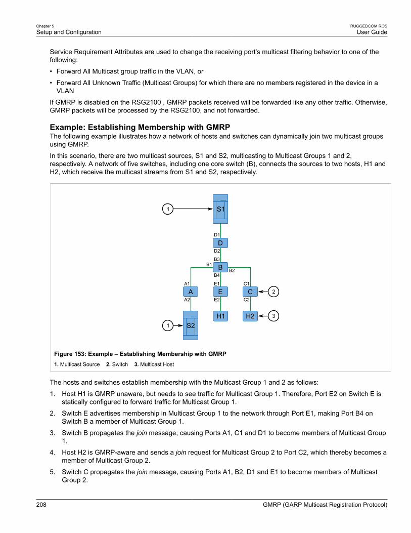
Chapter 5Setup and Configuration
RUGGEDCOM ROSUser Guide
208 GMRP (GARP Multicast Registration Protocol)
Service Requirement Attributes are used to change the receiving port's multicast filtering behavior to one of thefollowing:
• Forward All Multicast group traffic in the VLAN, or
• Forward All Unknown Traffic (Multicast Groups) for which there are no members registered in the device in aVLAN
If GMRP is disabled on the RSG2100 , GMRP packets received will be forwarded like any other traffic. Otherwise,GMRP packets will be processed by the RSG2100, and not forwarded.
Example: Establishing Membership with GMRPThe following example illustrates how a network of hosts and switches can dynamically join two multicast groupsusing GMRP.
In this scenario, there are two multicast sources, S1 and S2, multicasting to Multicast Groups 1 and 2,respectively. A network of five switches, including one core switch (B), connects the sources to two hosts, H1 andH2, which receive the multicast streams from S1 and S2, respectively.
A1
A2A E C
D
S1
S2H2H1
E1
E2
C1
C2
B3
B4
B1B2B
D1
D2
1
1
2
3
Figure 153: Example – Establishing Membership with GMRP1. Multicast Source 2. Switch 3. Multicast Host
The hosts and switches establish membership with the Multicast Group 1 and 2 as follows:
1. Host H1 is GMRP unaware, but needs to see traffic for Multicast Group 1. Therefore, Port E2 on Switch E isstatically configured to forward traffic for Multicast Group 1.
2. Switch E advertises membership in Multicast Group 1 to the network through Port E1, making Port B4 onSwitch B a member of Multicast Group 1.
3. Switch B propagates the join message, causing Ports A1, C1 and D1 to become members of Multicast Group1.
4. Host H2 is GMRP-aware and sends a join request for Multicast Group 2 to Port C2, which thereby becomes amember of Multicast Group 2.
5. Switch C propagates the join message, causing Ports A1, B2, D1 and E1 to become members of MulticastGroup 2.

RUGGEDCOM ROSUser Guide
Chapter 5Setup and Configuration
Viewing a List of IP Multicast Groups 209
Once GMRP-based registration has propagated through the network, multicast traffic from S1 and S2 can reachits destination as follows:
• Source S1 transmits multicast traffic to Port D2 which is forwarded via Port D1, which has previously become amember of Multicast Group 1.
• Switch B forwards the Group 1 multicast via Port B4 towards Switch E.
• Switch E forwards the Group 1 multicast via Port E2, which has been statically configured for membership inMulticast Group 1.
• Host H1, connected to Port E2, thus receives the Group 1 multicast.
• Source S2 transmits multicast traffic to Port A2, which is then forwarded via port A1, which has previouslybecome a member of Multicast Group 2.
• Switch B forwards the Group 2 multicast via Port B2 towards Switch C.
• Switch C forwards the Group 2 multicast via Port C2, which has previously become a member of Group 2.
• Ultimately, Host H2, connected to Port C2, receives the Group 2 multicast.
Section 5.9.2
Viewing a List of IP Multicast GroupsTo view a list of IP multicast groups, navigate to Multicast Filtering » View IP Multicast Groups. The IPMulticast Groups table appears.
Figure 154: IP Multicast Groups Table
This table provides the following information:
Parameter Description
VID Synopsis: 0 to 65535
The VLAN Identifier of the VLAN on which the multicast group operates.
IP Address Synopsis: ###.###.###.### where ### ranges from 0 to 255
The multicast group IP address.
Joined Ports Synopsis: Any combination of numbers valid for this parameter
All ports that subscribed to the multicast group traffic.
Router Ports Synopsis: Any combination of numbers valid for this parameter
All ports that have been manually configured or dynamically discovered (by observing routerspecific traffic) as ports that link to multicast routers.
MAC Address Synopsis: ##-##-##-##-##-## where ## ranges 0 to FF
The multicast MAC address corresponding to the group multicast IP address.
If the table is empty, do the following:
• Make sure traffic is being sent to the device.
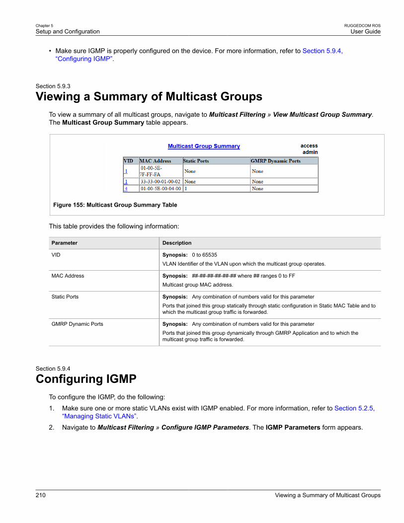
Chapter 5Setup and Configuration
RUGGEDCOM ROSUser Guide
210 Viewing a Summary of Multicast Groups
• Make sure IGMP is properly configured on the device. For more information, refer to Section 5.9.4,“Configuring IGMP”.
Section 5.9.3
Viewing a Summary of Multicast GroupsTo view a summary of all multicast groups, navigate to Multicast Filtering » View Multicast Group Summary.The Multicast Group Summary table appears.
Figure 155: Multicast Group Summary Table
This table provides the following information:
Parameter Description
VID Synopsis: 0 to 65535
VLAN Identifier of the VLAN upon which the multicast group operates.
MAC Address Synopsis: ##-##-##-##-##-## where ## ranges 0 to FF
Multicast group MAC address.
Static Ports Synopsis: Any combination of numbers valid for this parameter
Ports that joined this group statically through static configuration in Static MAC Table and towhich the multicast group traffic is forwarded.
GMRP Dynamic Ports Synopsis: Any combination of numbers valid for this parameter
Ports that joined this group dynamically through GMRP Application and to which themulticast group traffic is forwarded.
Section 5.9.4
Configuring IGMPTo configure the IGMP, do the following:
1. Make sure one or more static VLANs exist with IGMP enabled. For more information, refer to Section 5.2.5,“Managing Static VLANs”.
2. Navigate to Multicast Filtering » Configure IGMP Parameters. The IGMP Parameters form appears.

RUGGEDCOM ROSUser Guide
Chapter 5Setup and Configuration
Configuring IGMP 211
76
5
4
3
2
1
Figure 156: IGMP Parameters Form
1. Mode Options 2. Query Interval Box 3. Router Ports Box 4. Router Forwarding Options 5. RSTP Flooding Options 6. Apply Button 7. Reload Button
3. Configure the following parameter(s) as required:
Parameter Description
Mode Synopsis: { Passive, Active }Default: Passive
Specifies IGMP mode:
PASSIVE - the switch passively snoops IGMP traffic and never sends IGMP queries
ACTIVE - the switch generates IGMP queries, if no queries from a better candidate forbeing the querier are detected for a while.
Query Interval Synopsis: 10 to 3600Default: 60 s
The time interval between IGMP queries generated by the switch.
NOTEThis parameter also affects the Group Membership Interval (i.e. the groupsubscriber aging time), therefore, it takes effect even in PASSIVE mode.
Router Ports Synopsis: Any combination of numbers valid for this parameterDefault: None
This parameter specifies ports that connect to multicast routers. If you do not configureknown router ports, the switch may be able to detect them, however it is advisable topre-configure them.
Router Forwarding Synopsis: { Off, On }Default: On
This parameter specifies whether multicast streams will be always forwarded tomulticast routers.
STP Flooding Synopsis: { Off, On }Default: Off
This parameter specifies whether multicast streams will be flooded out of all STP non-edge ports upon topology change detection. Such flooding is desirable, if guaranteedmulticast stream delivery after topology change is most important.
4. Click Apply.

Chapter 5Setup and Configuration
RUGGEDCOM ROSUser Guide
212 Configuring GMRP Globally
Section 5.9.5
Configuring GMRP GloballyTo configure global settings for GMRP, do the following:
1. Navigate to Multicast Filtering » Configure Global GMRP Parameters. The Global GMRP Parametersform appears.
54
2
1
3
Figure 157: Global GMRP Parameters Form
1. GMRP Enable Options 2. RSTP Flooding Options 3. Leave Timer Box 4. Apply Button 5. Reload Button
2. Configure the following parameter(s) as required:
Parameter Description
GMRP Enable Synopsis: { No, Yes }Default: No
Globally enable or disable GMRP.
When GMRP is globally disabled, GMRP configurations on individual ports are ignored.When GMRP is globally enabled, each port can be individually configured.
RSTP Flooding Synopsis: { On, Off }Default: Off
This parameter specifies whether multicast streams will be flooded out of all RSTP non-edge ports upon topology change detection. Such flooding is desirable, if guaranteedmulticast stream delivery after topology change is most important.
Leave Timer Synopsis: 600 to 300000 msDefault: 4000 ms
Time (milliseconds) to wait after issuing Leave or LeaveAll before removing registeredmulticast groups. If Join messages for specific addresses are received before this timerexpires, the addresses will be kept registered.
3. Click Apply.
Section 5.9.6
Configuring GMRP for Specific Ethernet PortsTo configure GMRP for a specific Ethernet port, do the following:
1. Make sure the global settings for GMRP have been configured. For more information, refer to Section 5.9.5,“Configuring GMRP Globally”.

RUGGEDCOM ROSUser Guide
Chapter 5Setup and Configuration
Configuring GMRP for Specific Ethernet Ports 213
2. Navigate to Multicast Filtering » Configure Port GMRP Parameters. The Port GMRP Parameters tableappears.
Figure 158: Port GMRP Parameters Table
3. Select an Ethernet port. The Port GMRP Parameters form appears.
43
1
2
Figure 159: Port GMRP Parameters Form
1. Port(s) Box 2. GMRP List 3. Apply Button 4. Reload Button
4. Configure the following parameter(s) as required:
Parameter Description
Port(s) Synopsis: Any combination of numbers valid for this parameter
The port number as seen on the front plate silkscreen of the switch (or a list of ports, ifaggregated in a port trunk).
GMRP Synopsis: { Disabled, Adv Only, Adv&Learn }Default: Default: Disabled
Configures GMRP (GARP Multicast Registration Protocol) operation on the port. Thereare several GMRP operation modes:
• DISABLED - the port is not capable of any GMRP processing.• ADVERTISE ONLY - the port will declare all MCAST addresses existing in the switch
(configured or learned) but will not learn any MCAST addresses.• ADVERTISE & LEARN - the port will declare all MCAST Addresses existing in the
switch (configured or learned) and can dynamically learn MCAST addresses.
5. Click Apply.

Chapter 5Setup and Configuration
RUGGEDCOM ROSUser Guide
214 Managing Static Multicast Groups
Section 5.9.7
Managing Static Multicast GroupsThe following sections describe how to configure and manage a list of known static multicast groups on otherdevices:
• Section 5.9.7.1, “Viewing a List of Static Multicast Groups”
• Section 5.9.7.2, “Adding a Static Multicast Group”
• Section 5.9.7.3, “Deleting a Static Multicast Group”
Section 5.9.7.1
Viewing a List of Static Multicast GroupsTo view a list of static multicast groups, navigate to Multicast Filtering » Configure Static Multicast Groups.The Static Multicast Groups table appears.
Figure 160: Static Multicast Groups Table
If a static multicast group is not listed, add the group. For more information, refer to Section 5.9.7.2, “Adding aStatic Multicast Group”.
Section 5.9.7.2
Adding a Static Multicast GroupTo add a static multicast group from another device, do the following:
1. Navigate to Multicast Filtering » Configure Static Multicast Groups. The Static Multicast Groups tableappears.

RUGGEDCOM ROSUser Guide
Chapter 5Setup and Configuration
Adding a Static Multicast Group 215
1
Figure 161: Static Multicast Groups Table
1. InsertRecord
2. Click InsertRecord. The Static Multicast Groups form appears.
75
6
3
2
1
4
Figure 162: Static Multicast Groups Form
1. MAC Address Box 2. VID Box 3. CoS List 4. Ports Box 5. Apply Button 6. Delete Button 7. Reload Button
3. Configure the following parameter(s) as required:
Parameter Description
MAC Address Synopsis: ##-##-##-##-##-## where ## ranges 0 to FFDefault: 00-00-00-00-00-00
Multicast group MAC address.
VID Synopsis: 1 to 4094Default: 1VLAN Identifier of the VLAN upon which the multicast group operates.
CoS Synopsis: { N/A, Normal, Medium, High, Crit }Default: N/A
Prioritizes traffic for the specified MAC address. To not prioritize traffic based on theaddress, select N/A.
Ports Synopsis: Any combination of numbers valid for this parameterDefault: None
Ports to which the multicast group traffic is forwarded.

Chapter 5Setup and Configuration
RUGGEDCOM ROSUser Guide
216 Deleting a Static Multicast Group
4. Click Apply.
Section 5.9.7.3
Deleting a Static Multicast GroupTo delete a static multicast group, do the following:
1. Navigate to Multicast Filtering » Configure Static Multicast Groups. The Static Multicast Groups tableappears.
Figure 163: Static Multicast Groups Table
2. Select the group from the table. The Static Multicast Groups form appears.
75
6
3
2
1
4
Figure 164: Static Multicast Groups Form
1. MAC Address Box 2. VID Box 3. Priority Box 4. Ports Box 5. Apply Button 6. Delete Button 7. Reload Button
3. Click Delete.
Section 5.10
Managing Port SecurityPort security, or port access control, provides the ability to filter or accept traffic from specific MAC addresses.
Port security works by inspecting the source MAC addresses of received frames and validating them againstthe list of MAC addresses authorized by the port. Unauthorized frames are filtered and, optionally, the part

RUGGEDCOM ROSUser Guide
Chapter 5Setup and Configuration
Port Security Concepts 217
that received the frame can be shutdown permanently or for a specified period of time. An alarm will be raisedindicating the detected unauthorized MAC address.
Frames to unknown destination addresses are flooded through secure ports.
The following sections describe how to configure and manage port security:
• Section 5.10.1, “Port Security Concepts”
• Section 5.10.2, “Viewing a List of Authorized MAC Addresses”
• Section 5.10.3, “Configuring Port Security”
• Section 5.10.4, “Configuring IEEE 802.1X”
Section 5.10.1
Port Security ConceptsThe following sections describe some of the concepts important to the implementation of port security in ROS:
• Section 5.10.1.1, “Static MAC Address-Based Authentication”
• Section 5.10.1.2, “IEEE 802.1x Authentication”
• Section 5.10.1.3, “IEEE 802.1X Authentication with MAC Address-Based Authentication”
• Section 5.10.1.4, “Assigning VLANS with Tunnel Attributes”
Section 5.10.1.1
Static MAC Address-Based AuthenticationWith this method, the switch validates the source MAC addresses of received frames against the contents in theStatic MAC Address Table.
ROS also supports a highly flexible Port Security configuration which provides a convenient means for networkadministrators to use the feature in various network scenarios.
A Static MAC address can be configured without a port number being explicitly specified. In this case, theconfigured MAC address will be automatically authorized on the port where it is detected. This allows devices tobe connected to any secure port on the switch without requiring any reconfiguration.
The switch can also be programmed to learn (and, thus, authorize) a pre-configured number of the first sourceMAC addresses encountered on a secure port. This enables the capture of the appropriate secure addresseswhen first configuring MAC address-based authorization on a port. Those MAC addresses are automaticallyinserted into the Static MAC Address Table and remain there until explicitly removed by the user.
Section 5.10.1.2
IEEE 802.1x AuthenticationThe IEEE 802.1x standard defines a mechanism for port-based network access control and provides a means ofauthenticating and authorizing devices attached to LAN ports.
Although IEEE 802.1x is mostly used in wireless networks, this method is also implemented in wired switches.
The IEEE 802.1x standard defines three major components of the authentication method: Supplicant,Authenticator and Authentication server. ROS supports the Authenticator component.

Chapter 5Setup and Configuration
RUGGEDCOM ROSUser Guide
218IEEE 802.1X Authentication with MAC Address-Based
Authentication
1 2 3 4
Figure 165: IEEE 802.1x General Topology
1. Supplicant 2. Authenticator Switch 3. LAN 4. Authentication Server
IMPORTANT!ROS supports both Protected Extensible Authentication Protocol (PEAP) and EAP-MD5. PEAP is moresecure and is recommended if available in the supplicant.
IEEE 802.1x makes use of the Extensible Authentication Protocol (EAP), which is a generic PPP authenticationprotocol that supports various authentication methods. IEEE 802.1x defines a protocol for communicationbetween the Supplicant and the Authenticator, referred to as EAP over LAN (EAPOL).
ROS communicates with the Authentication Server using EAP over RADIUS.
NOTEThe switch supports authentication of one host per port.
NOTEIf the host’s MAC address is configured in the Static MAC Address Table, it will be authorized, even ifthe host authentication is rejected by the authentication server.
Section 5.10.1.3
IEEE 802.1X Authentication with MAC Address-Based AuthenticationThis method, also referred to as MAB (MAC-Authentication Bypass), is commonly used for devices, such as VoIPphones and Ethernet printers, that do not support the 802.1x protocol. This method allows such devices to beauthenticated using the same database infrastructure as that used in 802.1x.
IEEE 802.1x with MAC-Authentication Bypass works as follows:
1. The device connects to a switch port.
2. The switch learns the device MAC address upon receiving the first frame from the device (the device usuallysends out a DHCP request message when first connected).
3. The switch sends an EAP Request message to the device, attempting to start 802.1X authentication.
4. The switch times out while waiting for the EAP reply, because the device does not support 802.1x.
5. The switch sends an authentication message to the authentication server, using the device MAC address asthe username and password.
6. The switch authenticates or rejects the device according to the reply from the authentication server.

RUGGEDCOM ROSUser Guide
Chapter 5Setup and Configuration
Assigning VLANS with Tunnel Attributes 219
Section 5.10.1.4
Assigning VLANS with Tunnel AttributesROS supports assigning a VLAN to the authorized port using tunnel attributes, as defined in RFC 3580 [http://tools.ietf.org/html/rfc3580], when the Port Security mode is set to 802.1x or 802.1x/MAC-Auth.
In some cases, it may be desirable to allow a port to be placed into a particular VLAN, based on theauthentication result. For example:
• To allow a particular device, based on its MAC address, to remain on the same VLAN as it moves within anetwork, configure the switches for 802.1X/MAC-Auth mode
• To allow a particular user, based on the user’s login credentials, to remain on the same VLAN when the userlogs in from different locations, configure the switches for 802.1X mode
If the RADIUS server wants to use this feature, it indicates the desired VLAN by including tunnel attributes in theAccess-Accept message. The RADIUS server uses the following tunnel attributes for VLAN assignment:
• Tunnel-Type=VLAN (13)
• Tunnel-Medium-Type=802
• Tunnel-Private-Group-ID=VLANID
Note that VLANID is 12-bits and takes a value between 1 and 4094, inclusive. The Tunnel-Private-Group-ID isa string as defined in RFC 2868 [http://tools.ietf.org/html/rfc2868], so the VLANID integer value is encoded as astring.
If the tunnel attributes are not returned by the authentication server, the VLAN assigned to the switch portremains unchanged.
Section 5.10.2
Viewing a List of Authorized MAC AddressesTo view a list of static MAC addresses learned from secure ports, navigate to Port Security » View AuthorizedMAC Addresses. The Authorized MAC Addresses table appears.
NOTEOnly MAC addresses authorized on a static MAC port(s) are shown. MAC addresses authorized withIEEE 802.1X are not shown.
Figure 166: Authorized MAC Addresses Table
This table displays the following information:
Parameter Description
Port Synopsis: 1 to maximum port number
Port on which MAC address has been learned.
MAC Address Synopsis: ##-##-##-##-##-## where ## ranges 0 to FF
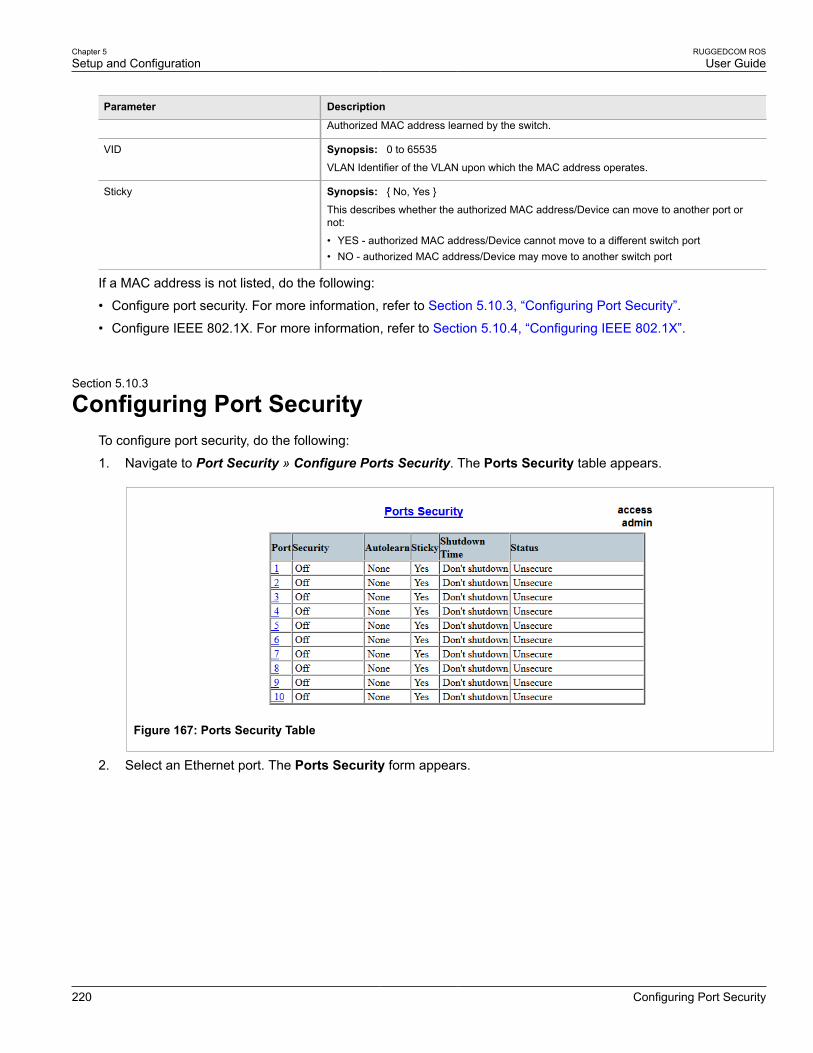
Chapter 5Setup and Configuration
RUGGEDCOM ROSUser Guide
220 Configuring Port Security
Parameter Description
Authorized MAC address learned by the switch.
VID Synopsis: 0 to 65535
VLAN Identifier of the VLAN upon which the MAC address operates.
Sticky Synopsis: { No, Yes }
This describes whether the authorized MAC address/Device can move to another port ornot:
• YES - authorized MAC address/Device cannot move to a different switch port• NO - authorized MAC address/Device may move to another switch port
If a MAC address is not listed, do the following:
• Configure port security. For more information, refer to Section 5.10.3, “Configuring Port Security”.
• Configure IEEE 802.1X. For more information, refer to Section 5.10.4, “Configuring IEEE 802.1X”.
Section 5.10.3
Configuring Port SecurityTo configure port security, do the following:
1. Navigate to Port Security » Configure Ports Security. The Ports Security table appears.
Figure 167: Ports Security Table
2. Select an Ethernet port. The Ports Security form appears.

RUGGEDCOM ROSUser Guide
Chapter 5Setup and Configuration
Configuring Port Security 221
87
6
5
4
3
2
1
Figure 168: Ports Security Form
1. Port Box 2. Security List 3. Autolearn Box 4. Sticky Options 5. Shutdown Time Box 6. Status Box 7. Apply Button 8. Reload Button
3. Configure the following parameter(s) as required:
Parameter Description
Port Synopsis: 1 to maximum port numberDefault: 1The port number as seen on the front plate silkscreen of the switch.
Security Synopsis: { Off, Static MAC, 802.1X, 802.1x/MAC-Auth }Default: Off
Enables or disables the port's security feature. Two types of port access control areavailable:
• Static MAC address-based. With this method, authorized MAC address(es) should beconfigured in the Static MAC Address table. If some MAC addresses are not knownin advance (or it is not known to which port they will be connected), there is still anoption to configure the switch to auto-learn certain number of MAC addresses. Oncelearned, they do not age out until the unit is reset or the link goes down.
• IEEE 802.1X standard authentication.• IEEE 802.1X with MAC-Authentication, also known as MAC-Authentication Bypass.
With this option, the device can authenticate clients based on the client’s MACaddress if IEEE 802.1X authentication times out.
Autolearn Synopsis: 1 to 16 or { None }Default: None
Only applicable when the 'Security' field has been set to 'Static MAC'. It specifiesmaximum number of MAC addresses that can be dynamically learned on the port.If there are static addresses configured on the port, the actual number of addressesallowed to be learned is this number minus the number of the static MAC addresses.
Sticky Synopsis: { No, Yes }Default: Yes
Only applicable when the 'Security' field has been set to 'Static MAC'. Change thebehaviour of the port to either sticky or non-sticky.
If Sticky is 'Yes', MACs/Devices authorized on the port 'stick' to the port and the switchwill not allow them to move to a different port.
If Sticky is 'No', MACs/Devices authorized on the port may move to another port.
Shutdown Time Synopsis: 1 to 86400 s or { Until reset, Don't shutdown }Default: Don't shutdown
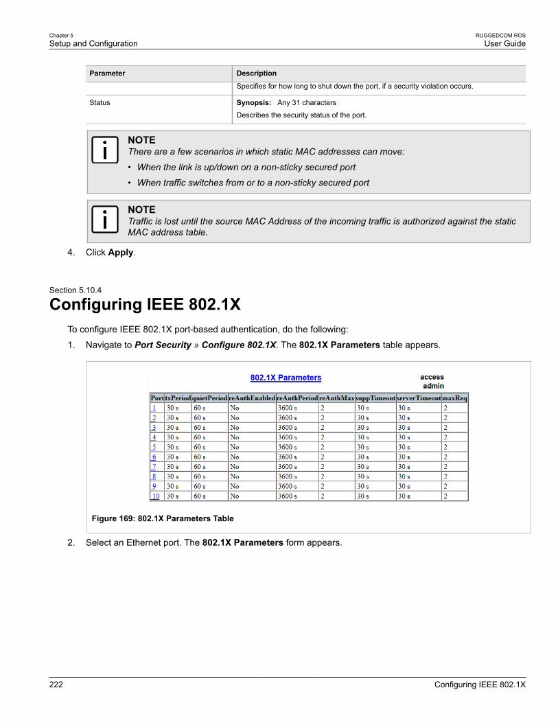
Chapter 5Setup and Configuration
RUGGEDCOM ROSUser Guide
222 Configuring IEEE 802.1X
Parameter Description
Specifies for how long to shut down the port, if a security violation occurs.
Status Synopsis: Any 31 characters
Describes the security status of the port.
NOTEThere are a few scenarios in which static MAC addresses can move:
• When the link is up/down on a non-sticky secured port
• When traffic switches from or to a non-sticky secured port
NOTETraffic is lost until the source MAC Address of the incoming traffic is authorized against the staticMAC address table.
4. Click Apply.
Section 5.10.4
Configuring IEEE 802.1XTo configure IEEE 802.1X port-based authentication, do the following:
1. Navigate to Port Security » Configure 802.1X. The 802.1X Parameters table appears.
Figure 169: 802.1X Parameters Table
2. Select an Ethernet port. The 802.1X Parameters form appears.
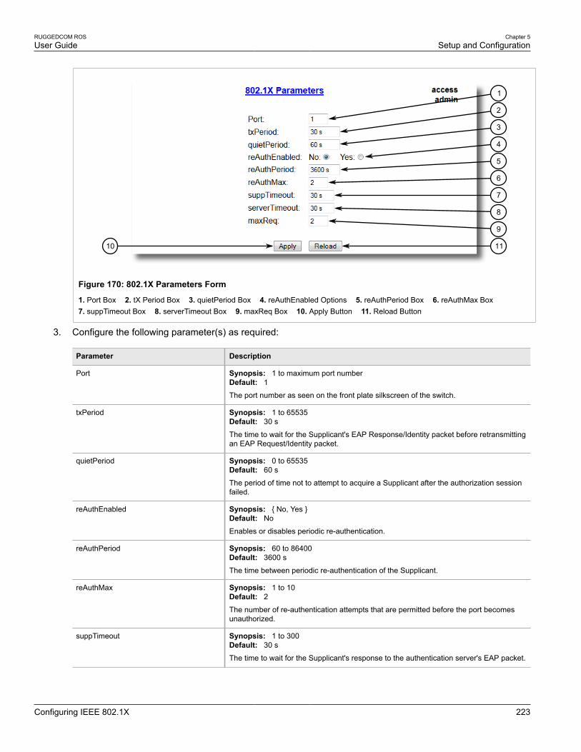
RUGGEDCOM ROSUser Guide
Chapter 5Setup and Configuration
Configuring IEEE 802.1X 223
1110
9
8
7
6
5
4
3
2
1
Figure 170: 802.1X Parameters Form
1. Port Box 2. tX Period Box 3. quietPeriod Box 4. reAuthEnabled Options 5. reAuthPeriod Box 6. reAuthMax Box 7. suppTimeout Box 8. serverTimeout Box 9. maxReq Box 10. Apply Button 11. Reload Button
3. Configure the following parameter(s) as required:
Parameter Description
Port Synopsis: 1 to maximum port numberDefault: 1The port number as seen on the front plate silkscreen of the switch.
txPeriod Synopsis: 1 to 65535Default: 30 s
The time to wait for the Supplicant's EAP Response/Identity packet before retransmittingan EAP Request/Identity packet.
quietPeriod Synopsis: 0 to 65535Default: 60 s
The period of time not to attempt to acquire a Supplicant after the authorization sessionfailed.
reAuthEnabled Synopsis: { No, Yes }Default: No
Enables or disables periodic re-authentication.
reAuthPeriod Synopsis: 60 to 86400Default: 3600 s
The time between periodic re-authentication of the Supplicant.
reAuthMax Synopsis: 1 to 10Default: 2The number of re-authentication attempts that are permitted before the port becomesunauthorized.
suppTimeout Synopsis: 1 to 300Default: 30 s
The time to wait for the Supplicant's response to the authentication server's EAP packet.

Chapter 5Setup and Configuration
RUGGEDCOM ROSUser Guide
224 Managing Link Aggregation
Parameter Description
serverTimeout Synopsis: 1 to 300Default: 30 s
The time to wait for the authentication server's response to the Supplicant's EAP packet.
maxReq Synopsis: 1 to 10Default: 2The maximum number of times to retransmit the authentication server's EAP Requestpacket to the Supplicant before the authentication session times out.
4. Click Apply.
Section 5.11
Managing Link AggregationLink aggregation, also referred to as port trunking or port bundling, provides the ability to aggregate or gatherseveral Ethernet ports into one logical link (port trunk) with higher bandwidth. This allows for highly randomizedload balancing between the aggregated links based on both the source and destination MAC addresses of theforwarded frames.
Link Aggregation can be used for two purposes:
• To obtain increased, linearly incremental link bandwidth.
• To improve network reliability by creating link redundancy. If one of the aggregated links fails, the switch willbalance the traffic between the remaining links.
21
Figure 171: Examples of Link Aggregation
1. Switch 2. Server

RUGGEDCOM ROSUser Guide
Chapter 5Setup and Configuration
Link Aggregation Concepts 225
ROS allows up to 15 port trunks to be configured on a single device, with each consisting of up to 8 ports.
NOTEThe maximum number of port trunks for each device depends on the number of ports available. Atleast two ports are required to configure a port trunk.
NOTEThe aggregated port with the lowest port number is called the Port Trunk Primary Port. Other ports inthe trunk are called Secondary Ports.
The following sections describe how to configure and manage link aggregation:
• Section 5.11.1, “Link Aggregation Concepts”
• Section 5.11.2, “Managing Port Trunks”
Section 5.11.1
Link Aggregation ConceptsThe following sections describe some of the concepts important to the implementation of link aggregation in ROS:
• Section 5.11.1.1, “Rules and Limitations”
• Section 5.11.1.2, “Link Aggregation and Layer 2 Features”
• Section 5.11.1.3, “Link Aggregation and Physical Layer Features”
Section 5.11.1.1
Rules and LimitationsThe implementation of link aggregation must adhere to the following rules and limitations:
• Each port can belong to only one port trunk at a time.
• A port mirroring target port can not be member of a port trunk. However, a port mirroring source port can bemember of a port trunk.
• A port working in QinQ mode cannot be a member of a port trunk.
• DHCP Relay Agent Client port cannot be a member of a port trunk.
• Load balancing between the links of a bundle is randomized and may not be ideal. For instance, if three 100Mbs links are aggregated, the resulting bandwidth of the port trunk may not be precisely 300 Mbs.
• A Static MAC Address should not be configured to reside on an aggregated port – it may cause some framesdestined for that address to be dropped.
• A secure port cannot be a member of a port trunk.
• The IEEE 802.3ad Link Aggregation standard requires all physical links in the port trunk to run at the samespeed and in full-duplex mode. If this requirement is violated, the performance of the port trunk will drop.
The switch will raise an appropriate alarm, if such a speed/duplex mismatch is detected.
• STP dynamically calculates the path cost of the port trunk based on its aggregated bandwidth. However, if theaggregated ports are running at different speeds, the path cost may not be calculated correctly.

Chapter 5Setup and Configuration
RUGGEDCOM ROSUser Guide
226 Link Aggregation and Layer 2 Features
• Enabling STP is the best way for handling link redundancy in switch-to-switch connections composed of morethan one physical link. If STP is enabled and increased bandwidth is not required, Link Aggregation should notbe used because it may lead to a longer fail-over time.
Section 5.11.1.2
Link Aggregation and Layer 2 FeaturesLayer 2 features (e.g. STP, VLAN, CoS, Multicast Filtering) treat a port trunk as a single link.
• If the Spanning Tree Protocol (STP) puts an aggregated port in blocking/forwarding, it does it for the whole porttrunk.
• If one of the aggregated ports joins/leaves a multicast group (e.g. via IGMP or GMRP), all other ports in thetrunk will join/leave too.
• Any port configuration parameter (e.g. VLAN, CoS) change will be automatically applied to all ports in the trunk.
• Configuration/status parameters of the secondary ports will not be shown and their port numbers will be simplylisted next to the primary port number in the appropriate configuration/status UI sessions.
• When a secondary port is added to a port trunk, it inherits all the configuration settings of the primary port.When this secondary port is removed from the port trunk, the settings it had previous to the aggregation arerestored.
Section 5.11.1.3
Link Aggregation and Physical Layer FeaturesPhysical layer features (e.g. physical link configuration, link status, rate limiting, Ethernet statistics) will still treateach aggregated port separately.
• Physical configuration/status parameters will NOT be automatically applied to other ports in the trunk and willbe displayed for each port as usual.
• Make sure that only ports with the same speed and duplex settings are aggregated. If auto-negotiation is used,make sure it is resolved to the same speed for all ports in the port trunk.
• To get a value of an Ethernet statistics counter for the port trunk, add the values of the counters for all ports inthe port trunk.
Section 5.11.2
Managing Port TrunksThe following sections describe how to configure and manage port trunks:
• Section 5.11.2.1, “Viewing a List of Port Trunks”
• Section 5.11.2.2, “Adding a Port Trunk”
• Section 5.11.2.3, “Deleting a Port Trunk”

RUGGEDCOM ROSUser Guide
Chapter 5Setup and Configuration
Viewing a List of Port Trunks 227
Section 5.11.2.1
Viewing a List of Port TrunksTo view a list of port trunks configured on the device, navigate to Link Aggregation » Configure Port Trunks.The Port Trunks table appears.
Figure 172: Port Trunks Table
If port trunks have not been configured, add trunks as needed. For more information, refer to Section 5.11.2.2,“Adding a Port Trunk”.
Section 5.11.2.2
Adding a Port TrunkTo add a port trunk, do the following:
IMPORTANT!The port trunk must be properly configured on both sides of the aggregated link. In switch-to-switchconnections, if the configuration of both sides does not match (i.e. some ports are mistakenly notincluded in the port trunk), it will result in a loop. Therefore, the following procedure is stronglyrecommended to configure a port trunk:
a. Disconnect or disable all the ports involved in the configuration, i.e. either being added to orremoved from the port trunk.
b. Configure the port trunk on both switches.
c. Double-check the port trunk configuration on both switches.
d. Reconnect or re-enable the ports.
If the port trunk is being configured while the ports are not disconnected or disabled, the port will beautomatically disabled for a few seconds.
1. Navigate to Link Aggregation » Configure Port Trunks. The Port Trunks table appears.
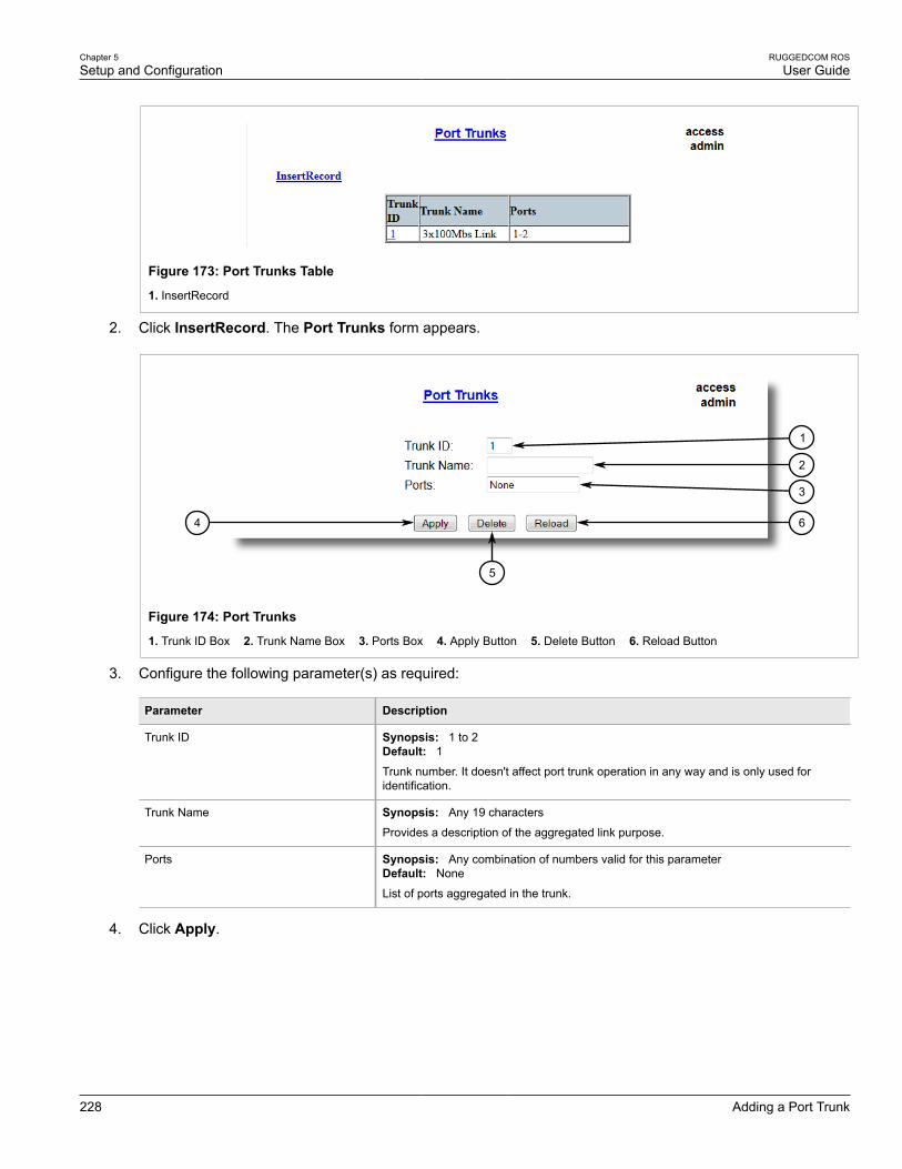
Chapter 5Setup and Configuration
RUGGEDCOM ROSUser Guide
228 Adding a Port Trunk
Figure 173: Port Trunks Table
1. InsertRecord
2. Click InsertRecord. The Port Trunks form appears.
64
5
2
1
3
Figure 174: Port Trunks
1. Trunk ID Box 2. Trunk Name Box 3. Ports Box 4. Apply Button 5. Delete Button 6. Reload Button
3. Configure the following parameter(s) as required:
Parameter Description
Trunk ID Synopsis: 1 to 2Default: 1Trunk number. It doesn't affect port trunk operation in any way and is only used foridentification.
Trunk Name Synopsis: Any 19 characters
Provides a description of the aggregated link purpose.
Ports Synopsis: Any combination of numbers valid for this parameterDefault: None
List of ports aggregated in the trunk.
4. Click Apply.
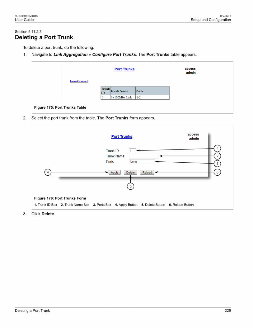
RUGGEDCOM ROSUser Guide
Chapter 5Setup and Configuration
Deleting a Port Trunk 229
Section 5.11.2.3
Deleting a Port TrunkTo delete a port trunk, do the following:
1. Navigate to Link Aggregation » Configure Port Trunks. The Port Trunks table appears.
Figure 175: Port Trunks Table
2. Select the port trunk from the table. The Port Trunks form appears.
64
5
2
1
3
Figure 176: Port Trunks Form1. Trunk ID Box 2. Trunk Name Box 3. Ports Box 4. Apply Button 5. Delete Button 6. Reload Button
3. Click Delete.

RUGGEDCOM ROSUser Guide
Chapter 5Setup and Configuration
Deleting a Port Trunk 230
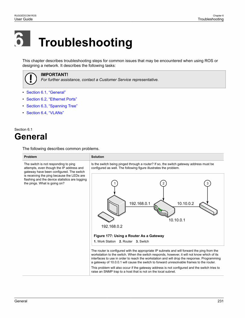
RUGGEDCOM ROSUser Guide
Chapter 6Troubleshooting
General 231
TroubleshootingThis chapter describes troubleshooting steps for common issues that may be encountered when using ROS ordesigning a network. It describes the following tasks:
IMPORTANT!For further assistance, contact a Customer Service representative.
• Section 6.1, “General”
• Section 6.2, “Ethernet Ports”
• Section 6.3, “Spanning Tree”
• Section 6.4, “VLANs”
Section 6.1
GeneralThe following describes common problems.
Problem Solution
The switch is not responding to pingattempts, even though the IP address andgateway have been configured. The switchis receiving the ping because the LEDs areflashing and the device statistics are loggingthe pings. What is going on?
Is the switch being pinged through a router? If so, the switch gateway address must beconfigured as well. The following figure illustrates the problem.
192.168.0.1
10.10.0.1
10.10.0.2
192.168.0.2
1 2 3
Figure 177: Using a Router As a Gateway1. Work Station 2. Router 3. Switch
The router is configured with the appropriate IP subnets and will forward the ping from theworkstation to the switch. When the switch responds, however, it will not know which of itsinterfaces to use in order to reach the workstation and will drop the response. Programminga gateway of 10.0.0.1 will cause the switch to forward unresolvable frames to the router.
This problem will also occur if the gateway address is not configured and the switch tries toraise an SNMP trap to a host that is not on the local subnet.
Chapter 6Troubleshooting
RUGGEDCOM ROSUser Guide
232 Ethernet Ports
Section 6.2
Ethernet PortsThe following describes common problems related to Ethernet ports.
Problem Solution
A link seems fine when traffic levels are low,but fails as traffic rates increase OR a linkcan be pinged but has problems with FTP/SQL/HTTP/etc.
A possible cause of intermittent operation is that of a ‘duplex mismatch’. If one end of thelink is fixed to full-duplex and the peer auto-negotiates, the auto-negotiating end falls back tohalf-duplex operation.
At lower traffic volumes, the link may display few if any errors. As the traffic volumerises, the fixed negotiation side will begin to experience dropped packets while the auto-negotiating side will experience collisions. Ultimately, as traffic loads approach 100%, thelink will become entirely unusable.
The ping command with flood options is a useful tool for testing commissioned links. Thecommand ping 192.168.0.1 500 2 can be used to issue 500 pings each separated bytwo milliseconds to the next switch. If the link used is of high quality, then no pings shouldbe lost and the average round trip time should be small.
Links are inaccessible, even when using theLink Fault Indication (LFI) protection feature.
Make sure LFI is not enabled on the peer as well. If both sides of the link have LFI enabled,then both sides will withhold link signal generation from each other.
Section 6.3
Spanning TreeThe following describes common problems related to the Spanning Tree Protocol (STP).
Problem Solution
The network locks up when a new port isconnected and the port status LEDs areflashing rapidly.
Occasionally, the ports seem to experiencesignificant flooding for a brief period of time.
A switch displays a strange behavior wherethe root port hops back and forth betweentwo switch ports and never settles down.
Is it possible that one of the switches in the network or one of the ports on a switch in thenetwork has STP disabled and accidentally connects to another switch? If this has occurred,then a traffic loop has been formed.
If the problem appears to be transient in nature, it is possible that ports that are part of thespanning tree have been configured as edge ports. After the link layers have come up onedge ports, STP will directly transition them (perhaps improperly) to the forwarding state.If an RSTP configuration message is then received, the port will be returned to blocking. Atraffic loop may be formed for the length of time the port was in forwarding.
If one of the switches appears to flip the root from one port to another, the problem may beone of traffic prioritization. For more information refer to "The network becomes unstablewhen a specific application is started."
Another possible cause of intermittent operation is that of an auto-negotiation mismatch.If one end of the link is fixed to full-duplex mode and the peer auto-negotiates, the auto-negotiating end will fall back to half-duplex operation. At lower traffic, the volumes thelink may display few if any errors. As the traffic volume rises, the fixed negotiation sidewill begin to experience dropped packets while the auto-negotiating side will experiencecollisions. Ultimately, as traffic loads approach 100%, the link will become entirely unusable.At this point, RSTP will not be able to transmit configuration messages over the link andthe spanning tree topology will break down. If an alternate trunk exists, RSTP will activateit in the place of the congested port. Since activation of the alternate port often relieves thecongested port of its traffic, the congested port will once again become reliable. RSTP willpromptly enter it back into service, beginning the cycle once again. The root port will flipback and forth between two ports on the switch.
A computer or device is connected to aswitch. After the switch is reset, it takes along time for it to come up.
Is it possible that the RSTP edge setting for this port is set to false? If Edge is set to false,the bridge will make the port go through two forward delay times before the port can send orreceive frames. If Edge is set to true, the bridge will transition the port directly to forwardingupon link up.

RUGGEDCOM ROSUser Guide
Chapter 6Troubleshooting
VLANs 233
Problem Solution
Another possible explanation is that some links in the network run in half-duplex mode.RSTP uses a peer-to-peer protocol called Proposal-Agreement to ensure transitioning in theevent of a link failure. This protocol requires full-duplex operation. When RSTP detects anon-full duplex port, it cannot rely on Proposal-Agreement protocol and must make the porttransition the slow (i.e. STP) way. If possible, configure the port for full-duplex operation.Otherwise, configure the port’s point-to-point setting to true.
Either one will allow the Proposal-Agreement protocol to be used.
When the switch is tested by deliberatelybreaking a link, it takes a long time beforedevices beyond the switch can be polled.
Is it possible that some ports participating in the topology have been configured to STPmode or that the port’s point-to-point parameter is set to false? STP and multipoint portsconverge slowly after failures occur.
Is it possible that the port has migrated to STP? If the port is connected to the LAN segmentby shared media and STP bridges are connected to that media, then convergence after linkfailure will be slow.
Delays on the order of tens or hundreds of milliseconds can result in circumstances wherethe link broken is the sole link to the root bridge and the secondary root bridge is poorlychosen. The worst of all possible designs occurs when the secondary root bridge is locatedat the farthest edge of the network from the root. In this case, a configuration message willhave to propagate out to the edge and then back in order to reestablish the topology.
The network is composed of a ring ofbridges, of which two (connected toeach other) are managed and the restare unmanaged. Why does the RSTPprotocol work quickly when a link is brokenbetween the managed bridges, but not in theunmanaged bridge part of the ring?
A properly operating unmanaged bridge is transparent to STP configuration messages. Themanaged bridges will exchange configuration messages through the unmanaged bridgepart of the ring as if it is non-existent. When a link in the unmanaged part of the ring failshowever, the managed bridges will only be able to detect the failure through timing out ofhello messages. Full connectivity will require three hello times plus two forwarding times tobe restored.
The network becomes unstable when aspecific application is started. The networkreturns to normal when the application isstopped.
RSTP sends its configuration messages using the highest possible priority level. If CoSis configured to allow traffic flows at the highest priority level and these traffic flows burstcontinuously to 100% of the line bandwidth, STP may be disrupted. It is therefore advisednot to use the highest CoS.
When a new port is brought up, the rootmoves on to that port instead of the port itshould move to or stay on.
Is it possible that the port cost is incorrectly programmed or that auto-negotiation derives anundesired value? Inspect the port and path costs with each port active as root.
An Intelligent Electronic Device (IED) orcontroller does not work with the device.
Certain low CPU bandwidth controllers have been found to behave less than perfectly whenthey receive unexpected traffic. Try disabling STP for the port.
If the controller fails around the time of a link outage, there is the remote possibility thatframe disordering or duplication may be the cause of the problem. Try setting the root port ofthe failing controller’s bridge to STP.
Polls to other devices are occassionally lost. Review the network statistics to determine whether the root bridge is receiving TopologyChange Notifications (TCNs) around the time of observed frame loss. It may be possiblethere are problems with intermittent links in the network.
The root is receiving a number of TCNs.Where are they coming from?
Examine the RSTP port statistics to determine the port from which the TCNs are arriving.Sign-on to the switch at the other end of the link attached to that port. Repeat this step untilthe switch generating the TCNs is found (i.e. the switch that is itself not receiving a largenumber of TCNs). Determine the problem at that switch.
Section 6.4
VLANsThe following describes common problems related to the VLANs.

Chapter 6Troubleshooting
RUGGEDCOM ROSUser Guide
234 VLANs
Problem Solution
VLANs are not needed on the network. Canthey be turned off?
Yes. Simply leave all ports set to type edge and leave the native VLAN set to 1. This is thedefault configuration for the switch.
Two VLANs were created and a number ofports were made members of them. Nowsome of the devices in one VLAN needto send messages to devices in the otherVLAN.
If the devices need to communicate at the physical address layer, they must be members ofthe same VLAN. If they can communicate in a Layer 3 fashion (i.e. using a protocol such asIP or IPX), use a router. The router will treat each VLAN as a separate interface, which willhave its own associated IP address space.
On a network of 30 switches, managementtraffic needs to be restricted to a separatedomain. What is the best method for doingthis while staying in contact with theseswitches?
At the switch where the management station is located, configure a port to use the newmanagement VLAN as its native VLAN. Configure a host computer to act as a temporarymanagement station.
At each switch, configure the management VLAN to the new value. Contact with eachindividual switch will be lost immediately as they are being configured, but it should bepossible re-establish communication from the temporary management station. After allswitches have been taken to the new management VLAN, configure the ports of all attachedmanagement devices to use the new VLAN.
NOTEEstablishing a management domain is often accompanied with theestablishment of an IP subnet specifically for the managed devices.