introduction 1 2 ruggedcom rx1500 3 4 5 6 - siemens ag · 2.3.2 mounting the device on a din rail...
TRANSCRIPT
RUGGEDCOM RX1500
Installation Guide
07/2018RC1053-EN-09
Preface
Introduction 1
Installing the Device 2
Device Management 3
Modules 4
Technical Specifications 5
Certification 6
RUGGEDCOM RX1500Installation Guide
ii
Copyright © 2018 Siemens Canada LtdAll rights reserved. Dissemination or reproduction of this document, or evaluation and communication of its contents, is not authorizedexcept where expressly permitted. Violations are liable for damages. All rights reserved, particularly for the purposes of patent application ortrademark registration.This document contains proprietary information, which is protected by copyright. All rights are reserved. No part of this document may bephotocopied, reproduced or translated to another language without the prior written consent of Siemens Canada Ltd.
Disclaimer Of LiabilitySiemens has verified the contents of this document against the hardware and/or software described. However, deviations between the productand the documentation may exist.Siemens shall not be liable for any errors or omissions contained herein or for consequential damages in connection with the furnishing,performance, or use of this material.The information given in this document is reviewed regularly and any necessary corrections will be included in subsequent editions. Weappreciate any suggested improvements. We reserve the right to make technical improvements without notice.
Registered TrademarksRUGGEDCOM™ and ROS™ are trademarks of Siemens Canada Ltd.Linux® is the registered trademark of Linus Torvalds in the United States and other countries.The registered trademark Linux® is used pursuant to a sublicense from LMI, the exclusive licensee of Linus Torvalds, owner of the mark on aworld-wide basis.Other designations in this manual might be trademarks whose use by third parties for their own purposes would infringe the rights of theowner.
Security InformationSiemens provides products and solutions with industrial security functions that support the secure operation of plants, machines, equipmentand/or networks. They are important components in a holistic industrial security concept. With this in mind, Siemens' products and solutionsundergo continuous development. Siemens recommends strongly that you regularly check for product updates.For the secure operation of Siemens products and solutions, it is necessary to take suitable preventive action (e.g. cell protection concept) andintegrate each component into a holistic, state-of-the-art industrial security concept. Third-party products that may be in use should also beconsidered. For more information about industrial security, visit https://www.siemens.com/industrialsecurity.To stay informed about product updates as they occur, sign up for a product-specific newsletter. For more information, visit https://support.automation.siemens.com.
WarrantySiemens warrants this product for a period of five (5) years from the date of purchase, conditional upon the return to factory for maintenanceduring the warranty term. This product contains no user-serviceable parts. Attempted service by unauthorized personnel shall render allwarranties null and void. The warranties set forth in this article are exclusive and are in lieu of all other warranties, performance guaranteesand conditions whether written or oral, statutory, express or implied (including all warranties and conditions of merchantability and fitness fora particular purpose, and all warranties and conditions arising from course of dealing or usage or trade). Correction of nonconformities in themanner and for the period of time provided above shall constitute the Seller’s sole liability and the Customer’s exclusive remedy for defectiveor nonconforming goods or services whether claims of the Customer are based in contract (including fundamental breach), in tort (includingnegligence and strict liability) or otherwise.For warranty details, visit https://www.siemens.com/ruggedcom or contact a Siemens customer service representative.
Contacting SiemensAddressSiemens Canada Ltd
TelephoneToll-free: 1 888 264 0006

RUGGEDCOM RX1500Installation Guide
iii
Industry Sector300 Applewood CrescentConcord, OntarioCanada, L4K 5C7
Tel: +1 905 856 5288Fax: +1 905 856 1995
Webhttps://www.siemens.com/ruggedcom

RUGGEDCOM RX1500Installation Guide
iv
RUGGEDCOM RX1500Installation Guide
Table of Contents
v
Table of ContentsPreface ............................................................................................................ vii
Alerts ................................................................................................................................................. viiRelated Documents ............................................................................................................................ viiiAccessing Documentation .................................................................................................................. viiiTraining ............................................................................................................................................ viiiCustomer Support .............................................................................................................................. viii
Chapter 1Introduction ..................................................................................................... 1
1.1 Feature Highlights ........................................................................................................................ 11.2 Description ................................................................................................................................... 21.3 Required Tools and Materials ......................................................................................................... 31.4 Decommissioning and Disposal ...................................................................................................... 31.5 Cabling Recommendations ............................................................................................................ 3
1.5.1 Protection On Twisted-Pair Data Ports .................................................................................. 41.5.2 Gigabit Ethernet 1000Base-TX Cabling Recommendations ..................................................... 4
Chapter 2Installing the Device ......................................................................................... 5
2.1 General Procedure ........................................................................................................................ 62.2 Unpacking the Device ................................................................................................................... 62.3 Mounting the Device .................................................................................................................... 6
2.3.1 Mounting the Device to a Rack ........................................................................................... 72.3.2 Mounting the Device on a DIN Rail ...................................................................................... 82.3.3 Mounting the Device to a Panel .......................................................................................... 9
2.4 Connecting the Failsafe Alarm Relay .............................................................................................. 92.5 Connecting Power ....................................................................................................................... 10
2.5.1 Connecting High AC/DC Power .......................................................................................... 112.5.2 Connecting Low DC Power ................................................................................................ 12
Chapter 3Device Management ....................................................................................... 15
3.1 Connecting to the Device ............................................................................................................ 153.2 Configuring the Device ................................................................................................................ 163.3 Accessing the CompactFlash Card ................................................................................................ 17
Table of Contents
RUGGEDCOM RX1500Installation Guide
vi
Chapter 4Modules .......................................................................................................... 19
4.1 Available Modules ....................................................................................................................... 194.2 Installing/Removing Line Modules ................................................................................................ 284.3 Installing/Removing Power Modules ............................................................................................. 29
Chapter 5Technical Specifications .................................................................................. 33
5.1 Power Supply Specifications ........................................................................................................ 335.2 Failsafe Relay Specifications ......................................................................................................... 345.3 Operating Environment ............................................................................................................... 345.4 Mechanical Specifications ............................................................................................................ 345.5 Dimension Drawings ................................................................................................................... 34
Chapter 6Certification .................................................................................................... 39
6.1 Approvals ................................................................................................................................... 396.1.1 TÜV SÜD ......................................................................................................................... 396.1.2 European Union (EU) ....................................................................................................... 406.1.3 FCC ................................................................................................................................. 416.1.4 FDA/CDRH ........................................................................................................................ 416.1.5 ISED ................................................................................................................................ 416.1.6 ACMA .............................................................................................................................. 416.1.7 RoHS ............................................................................................................................... 426.1.8 Other Approvals ............................................................................................................... 42
6.2 EMC and Environmental Type Tests .............................................................................................. 42

RUGGEDCOM RX1500Installation Guide
Preface
Alerts vii
PrefaceThis guide describes the RUGGEDCOM RUGGEDCOM RX1500. It describes the major features of the device,installation, commissioning and important technical specifications.It is intended for use by network technical support personnel who are responsible for the installation,commissioning and maintenance of the device. It is also recommended for use by network and system planners,system programmers, and line technicians.
CONTENTS• “Alerts”• “Related Documents”• “Accessing Documentation”• “Training”• “Customer Support”
AlertsThe following types of alerts are used when necessary to highlight important information.
DANGER!DANGER alerts describe imminently hazardous situations that, if not avoided, will result in death orserious injury.
WARNING!WARNING alerts describe hazardous situations that, if not avoided, may result in serious injury and/orequipment damage.
CAUTION!CAUTION alerts describe hazardous situations that, if not avoided, may result in equipment damage.
IMPORTANT!IMPORTANT alerts provide important information that should be known before performing a procedureor step, or using a feature.
NOTENOTE alerts provide additional information, such as facts, tips and details.
Preface
RUGGEDCOM RX1500Installation Guide
viii Related Documents
Related DocumentsOther documents that may be of interest include:• RUGGEDCOM ROX II CLI User Guide [https://support.industry.siemens.com/cs/ww/en/view/109481699]• RUGGEDCOM ROX II Web Interface User Guide [https://support.industry.siemens.com/cs/ww/en/
view/109481700]• RUGGEDCOM ROX II Modules Catalog [https://support.industry.siemens.com/cs/ww/en/view/109747072]
Accessing DocumentationThe latest user documentation for RUGGEDCOM RX1500 is available online athttps://www.siemens.com/ruggedcom. To request or inquire about a user document, contact Siemens CustomerSupport.
TrainingSiemens offers a wide range of educational services ranging from in-house training of standard courses onnetworking, Ethernet switches and routers, to on-site customized courses tailored to the customer's needs,experience and application.Siemens' Educational Services team thrives on providing our customers with the essential practical skills to makesure users have the right knowledge and expertise to understand the various technologies associated with criticalcommunications network infrastructure technologies.Siemens' unique mix of IT/Telecommunications expertise combined with domain knowledge in the utility,transportation and industrial markets, allows Siemens to provide training specific to the customer's application.For more information about training services and course availability, visit https://www.siemens.com/ruggedcom orcontact a Siemens Sales representative.
Customer SupportCustomer support is available 24 hours, 7 days a week for all Siemens customers. For technical support or generalinformation, contact Siemens Customer Support through any of the following methods:
OnlineVisit http://www.siemens.com/automation/support-request to submit a Support Request (SR) or checkon the status of an existing SR.
TelephoneCall a local hotline center to submit a Support Request (SR). To locate a local hotline center, visit http://www.automation.siemens.com/mcms/aspa-db/en/automation-technology/Pages/default.aspx.
RUGGEDCOM RX1500Installation Guide
Preface
Customer Support ix
Mobile AppInstall the Industry Online Support app by Siemens AG on any Android, Apple iOS or Windows mobiledevice and be able to:• Access Siemens' extensive library of support documentation, including FAQs and manuals• Submit SRs or check on the status of an existing SR• Contact a local Siemens representative from Sales, Technical Support, Training, etc.• Ask questions or share knowledge with fellow Siemens customers and the support community

Preface
RUGGEDCOM RX1500Installation Guide
x Customer Support
RUGGEDCOM RX1500Installation Guide
Chapter 1Introduction
Feature Highlights 1
IntroductionThe RUGGEDCOM RUGGEDCOM RX1500 is a cost-efficient, rugged Layer 3 switch and router. The RUGGEDCOMRX1500’s modular and field replaceable platform can be equipped with WAN, serial, and Ethernet options, makingit ideally suited for electric power utilities, the industrial plant floor, and traffic control systems.The RUGGEDCOM RX1500 is designed to provide a high level of immunity to electromagnetic interference (EMI)and heavy electrical surges typical of the harsh environments found in many industrial applications. An operatingtemperature range of -40 to 85 °C (-40 to 185 °F) allows the RUGGEDCOM RX1500 to be placed in almost anylocation.
CONTENTS• Section 1.1, “Feature Highlights”• Section 1.2, “Description”• Section 1.3, “Required Tools and Materials”• Section 1.4, “Decommissioning and Disposal”• Section 1.5, “Cabling Recommendations”
Section 1.1
Feature HighlightsReliability in Harsh Environments
• Immunity to EMI and high voltage electricaltransients
• -40 to 85 °C (-40 to 185 °F) operating temperature(no fans)
• Failsafe output relay for critical failure or erroralarming
Universal Power Supply Options
• Dual redundant, modular, hot-swappable powersupplies
• Fully integrated power supplies (no externaladapters)
• Input voltage ranges: 13-36 VDC and 37-72 VDCor 85-264 VAC and 88-300 VDC for worldwideoperability
• CSA/UL 60950-1 safety approved to 85 °C (185 °F)
Physical Ports
• Field replaceable line modules• Up to 24 100Base-FX ports• Up to 24 10/100Base-TX ports• Up to 12 10Base-FL/100Base-SX ports• Up to 8 Gigabit Ethernet ports• Up to 24 serial ports• Up to 4 T1/E1 RJ48C ports or 2 E1 BNC ports• Up to 2 DDS (Digital Data Services) ports• Up to 8 active cellular data interfaces

Chapter 1Introduction
RUGGEDCOM RX1500Installation Guide
2 Description
Section 1.2
DescriptionThe RUGGEDCOM RX1500 features various ports, controls and indicator LEDs on the front panel for connecting,configuring and troubleshooting the device.
1 2 3 8
6 74
5
Figure 1: RUGGEDCOM RX1500
1. Management Port 2. RS232 Serial Console Port (DB9) 3. Utility USB Port 4. Port Status LEDs 5. Power Status LEDs 6. AlarmIndicator LED 7. Lamp Test/Alarm Cut-Off (LT/ACO) Button 8. Compact Flash Card Port
Management Port This 10/100Base-T Ethernet port is used for system management that is out-of-band from theswitch fabric.
RS-232 Serial Console Port The serial console port is for interfacing directly with the device and accessing initialmanagement functions. For information about connecting to the device via the serialconsole port, refer to Section 3.1, “Connecting to the Device”.
Utility USB Port Use the USB port to upgrade the ROX II software or install files, such as configuration filesand feature key files. For more information, refer to the RUGGEDCOM ROX II User Guide forthe RUGGEDCOM RX1500.
Lamp Test/Alarm Cut-Off (LT/ACO) Button This button performs two functions:• Press and hold this button to test all indicator LEDs• Press and release this button to acknowledge an active alarm
Power Status LEDs Indicates the status of the power modules.• I = The power module is receiving power• O = The power module is supplying power
Port Status LEDs Indicates when ports are active.• Green = OK• Orange = Warning alert• Red = Configuration error
Alarm Indicator LED Indicates when an alarm condition exists.• Green = Alarms cleared/acknowledged• Red = Alarm
Compact Flash Card Port Houses the CompactFlash (CF) card that contains active and backup installations ofRUGGEDCOM ROX II, along with the configuration database and other system data. For moreinformation, refer to Section 3.3, “Accessing the CompactFlash Card”.
RUGGEDCOM RX1500Installation Guide
Chapter 1Introduction
Required Tools and Materials 3
Section 1.3
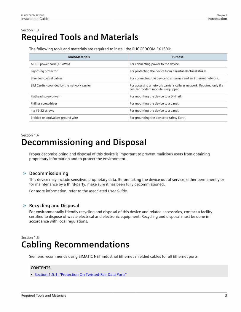
Required Tools and MaterialsThe following tools and materials are required to install the RUGGEDCOM RX1500:
Tools/Materials Purpose
AC/DC power cord (16 AWG) For connecting power to the device.
Lightning protector For protecting the device from harmful electrical strikes.
Shielded coaxial cables For connecting the device to antennas and an Ethernet network.
SIM Card(s) provided by the network carrier For accessing a network carrier's cellular network. Required only if acellular modem module is equipped.
Flathead screwdriver For mounting the device to a DIN rail.
Phillips screwdriver For mounting the device to a panel.
4 x #6-32 screws For mounting the device to a panel.
Braided or equivalent ground wire For grounding the device to safety Earth.
Section 1.4
Decommissioning and DisposalProper decomissioning and disposal of this device is important to prevent malicious users from obtainingproprietary information and to protect the environment.
DecommissioningThis device may include sensitive, proprietary data. Before taking the device out of service, either permanently orfor maintenance by a third-party, make sure it has been fully decommissioned.For more information, refer to the associated User Guide.
Recycling and DisposalFor environmentally friendly recycling and disposal of this device and related accessories, contact a facilitycertified to dispose of waste electrical and electronic equipment. Recycling and disposal must be done inaccordance with local regulations.
Section 1.5
Cabling RecommendationsSiemens recommends using SIMATIC NET industrial Ethernet shielded cables for all Ethernet ports.
CONTENTS• Section 1.5.1, “Protection On Twisted-Pair Data Ports”

Chapter 1Introduction
RUGGEDCOM RX1500Installation Guide
4 Protection On Twisted-Pair Data Ports
• Section 1.5.2, “Gigabit Ethernet 1000Base-TX Cabling Recommendations”
Section 1.5.1
Protection On Twisted-Pair Data PortsAll copper Ethernet ports on RUGGEDCOM products include transient suppression circuitry to protect againstdamage from electrical transients and conform with IEC 61850-3 and IEEE 1613 Class 1 standards. This meansthat during a transient electrical event, communications errors or interruptions may occur, but recovery isautomatic.Siemens also does not recommend using copper Ethernet ports to interface with devices in the field acrossdistances that could produce high levels of ground potential rise (i.e. greater than 2500 V), during line-to-groundfault conditions.
Section 1.5.2
Gigabit Ethernet 1000Base-TX Cabling RecommendationsThe IEEE 802.3ab Gigabit Ethernet standard defines 1000 Mbit/s Ethernet communications over distances of upto 100 m (328 ft) using all 4 pairs in category 5 (or higher) balanced, unshielded twisted-pair cabling. For wiringguidelines, system designers and integrators should refer to the Telecommunications Industry Association (TIA)TIA/EIA-568-A wiring standard that characterizes minimum cabling performance specifications required for properGigabit Ethernet operation. For reliable, error-free data communication, new and pre-existing communicationpaths should be verified for TIA/EIA-568-A compliance.The following table summarizes the relevant cabling standards:
Cabling Category 1000Base-TX Compliant Required Action
< 5 No New wiring infrastructure required.
5 Yes Verify TIA/EIA-568-A compliance.
5e Yes No action required. New installations should be designed with Category 5e or higher.
6 Yes No action required.
> 6 Yes Connector and wiring standards to be determined.
Follow these recommendations for copper data cabling in high electrical noise environments:• Data cable lengths should be as short as possible, preferably 3 m (10 ft) in length. Copper data cables should
not be used for inter-building communications.• Power and data cables should not be run in parallel for long distances, and should be installed in separate
conduits. Power and data cables should intersect at 90° angles when necessary to reduce inductive coupling.
RUGGEDCOM RX1500Installation Guide
Chapter 2Installing the Device
5
Installing the DeviceThis chapter describes how to install the device, including mounting the device, connecting power, andconnecting the device to the network.
DANGER!Electrocution hazard – risk of serious personal injury and/or damage to equipment. Before performingany maintenance tasks, make sure all power to the device has been disconnected and waitapproximately two minutes for any remaining energy to dissipate.
WARNING!Radiation hazard – risk of serious personal injury. This product contains a laser system and is classifiedas a CLASS 1 LASER PRODUCT. Use of controls or adjustments or performance of procedures otherthan those specified herein may result in hazardous radiation exposure.
WARNING!Radiation hazard – risk of Radio Frequency (RF) exposure. This device is compliant with therequirements set forth in FCC 47 CFR, section 1.1307, addressing Radio Frequency (RF) exposure fromradio frequency base stations, as defined in FCC OET Bulletin 65 [http://transition.fcc.gov/Bureaus/Engineering_Technology/Documents/bulletins/oet65/oet65.pdf]. The emitted radiation should be aslittle as possible. To achieve minimum RF exposure, install the device when it is configured not totransmit and set it to operational mode remotely, rather than having a technician enable transmissionon-site. For maintenance of the base station, or other operations which require RF exposure, theexposure should be minimized in time and according to the regulations set forth by the country ofinstallation or the Federal Communications Commission (FCC).
IMPORTANT!This product contains no user-serviceable parts. Attempted service by unauthorized personnel shallrender all warranties null and void.Changes or modifications not expressly approved by Siemens Canada Ltd could invalidatespecifications, test results, and agency approvals, and void the user's authority to operate theequipment.
IMPORTANT!This product should be installed in a restricted access location where access can only be gained byauthorized personnel who have been informed of the restrictions and any precautions that must betaken. Access must only be possible through the use of a tool, lock and key, or other means of security,and controlled by the authority responsible for the location.
CONTENTS• Section 2.1, “General Procedure”• Section 2.2, “Unpacking the Device”• Section 2.3, “Mounting the Device”
Chapter 2Installing the Device
RUGGEDCOM RX1500Installation Guide
6 General Procedure
• Section 2.4, “Connecting the Failsafe Alarm Relay”• Section 2.5, “Connecting Power”
Section 2.1
General ProcedureThe general procedure for installing the device is as follows:1. Review the relevant certification information for any regulatory requirements. For more information, refer to
Section 6.1, “Approvals”.2. Review the RUGGEDCOM RX1500 Series Modules Catalog for special installation or regulatory requirements
related to the modules installed in the device. In the case of cellular modem line modules, this includesantenna installation and regulatory requirements.
3. Mount the device.4. Connect the failsafe alarm relay.5. Connect power to the device and ground the device to safety Earth.6. Connect the device to the network.7. Configure the device.
Section 2.2
Unpacking the DeviceWhen unpacking the device, do the following:1. Inspect the package for damage before opening it.2. Visually inspect each item in the package for any physical damage.3. Verify all items are included.
IMPORTANT!If any item is missing or damaged, contact Siemens for assistance.
Section 2.3
Mounting the DeviceThe RUGGEDCOM RX1500 is designed for maximum mounting and display flexibility. It can be equipped withconnectors that allow it to be installed in a 48 cm (19 in) rack, 35 mm (1.4 in) DIN rail or directly on a panel.
IMPORTANT!Heat generated by the device is channeled outwards from the enclosure. As such, it is recommendedthat 2.5 cm (1 in) of space be maintained on all open sides of the device to allow for someconvectional airflow.
RUGGEDCOM RX1500Installation Guide
Chapter 2Installing the Device
Mounting the Device to a Rack 7
Forced airflow is not required. However, any increase in airflow will result in a reduction of ambienttemperature and improve the long-term reliability of all equipment mounted in the rack space.
NOTEFor detailed dimensions of the device with either rack, DIN rail or panel hardware installed, refer toSection 5.5, “Dimension Drawings”.
CONTENTS• Section 2.3.1, “Mounting the Device to a Rack”• Section 2.3.2, “Mounting the Device on a DIN Rail”• Section 2.3.3, “Mounting the Device to a Panel”
Section 2.3.1
Mounting the Device to a RackFor rack mount installations, the RUGGEDCOM RX1500 can be equipped with rack mount adapters pre-installed atthe front or rear of the chassis. Additional adapters are provided for added stability.
CAUTION!Vibration hazard – risk of damage to the device. Always use four rack mount adapters (two at the frontof the device and two at the rear) when installing the device in high-vibration or seismically activelocations.
CAUTION!Electrical/mechanical hazard – risk of damage to the device. Before installing the device in a rack,make sure of the following:• When installing the device in a closed or multi-device rack, be aware that the operating ambient
temperature of the rack may be higher than the ambient temperature of the room. Make sure therack is installed in a suitable environment that can withstand the maximum ambient temperaturegenerated by the rack.
• Do not exceed the maximum number of devices or weight restrictions specified by the rackmanufacturer.
• Do not overload the supply circuit. Refer to the over-current protection and power supply ratingsspecified by the rack manufacturer.
• Make sure the rack and all devices have a proper ground-to-Earth connection. Pay particularattention to power supply connections other than direct connections to the branch circuit (e.g. powerstrips).
To secure the device to a standard 48 cm (19 in) rack, do the following:1. Make sure the rack mount adapters are installed on the correct side of the chassis.
• To make the modules and ports accessible, install the rack mount adapters at the rear of the chassis• To make the management ports and LEDs accessible, install the rack mount adapters at the front of the
chassis

Chapter 2Installing the Device
RUGGEDCOM RX1500Installation Guide
8 Mounting the Device on a DIN Rail
NOTEThe chassis features multiple mounting holes, allowing the rack mount adapters to be installed upto 25 mm (1 in) from the face of the device.
3 3
1 2
Figure 2: Rack Mount Adapters
1. Rear 2. Front 3. Rack Mount Adapter
2. If required, install adapters on the opposite side of the device to protect from vibrations.3. Insert the device into the rack.4. Secure the adapters to the rack using the supplied hardware.
Section 2.3.2
Mounting the Device on a DIN RailFor DIN rail installations, the RUGGEDCOM RX1500 can be equipped with panel/DIN rail adapters pre-installed oneach side of the chassis. The adapters allow the device to be slid onto a standard 35 mm (1.4 in) DIN rail.To mount the device to a DIN rail, do the following:1. Align the adapters with the DIN rails and slide the device into place.
3
1
2
2
1
Figure 3: DIN Rail Mounting
1. Panel/DIN Rail Adapter 2. DIN Rail 3. Screw
2. Install one of the supplied screws on either side of the device to secure the adapters to the DIN rails.

RUGGEDCOM RX1500Installation Guide
Chapter 2Installing the Device
Mounting the Device to a Panel 9
Section 2.3.3
Mounting the Device to a PanelFor panel installations, the RUGGEDCOM RX1500 can be equipped with panel/DIN rail adapters pre-installed oneach side of the chassis. The adapters allow the device to be attached to a panel using screws.To mount the device to a panel, do the following:1. Place the device against the panel and mark the mounting holes on the panel.
21
1
Figure 4: Panel Mounting
1. Screw 2. Panel/DIN Rail Adapter
2. Prepare the mounting holes3. Align the device with the mounting holes and secure it to the panel.
Section 2.4
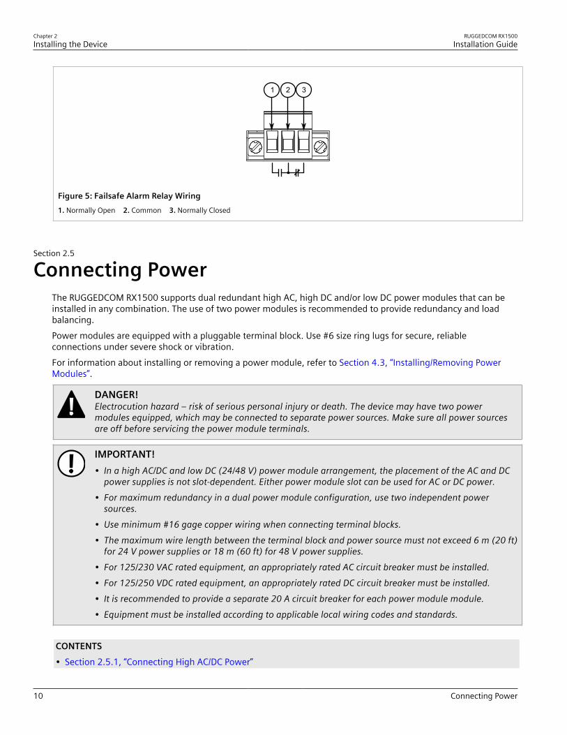
Connecting the Failsafe Alarm RelayThe failsafe relay can be configured to latch based on alarm conditions. The NO (Normally Open) contact is closedwhen the unit is powered and there are no active alarms. If the device is not powered or if an active alarm isconfigured, the relay opens the NO contact and closes the NC (Normally Closed) contact.
NOTEControl of the failsafe relay output is configurable through ROX II. One common application for thisrelay is to signal an alarm if a power failure occurs. For more information, refer to the ROX II UserGuide for the RUGGEDCOM RX1500.
The following shows the proper relay connections.
Chapter 2Installing the Device
RUGGEDCOM RX1500Installation Guide
10 Connecting Power
2 31
Figure 5: Failsafe Alarm Relay Wiring1. Normally Open 2. Common 3. Normally Closed
Section 2.5
Connecting PowerThe RUGGEDCOM RX1500 supports dual redundant high AC, high DC and/or low DC power modules that can beinstalled in any combination. The use of two power modules is recommended to provide redundancy and loadbalancing.Power modules are equipped with a pluggable terminal block. Use #6 size ring lugs for secure, reliableconnections under severe shock or vibration.For information about installing or removing a power module, refer to Section 4.3, “Installing/Removing PowerModules”.
DANGER!Electrocution hazard – risk of serious personal injury or death. The device may have two powermodules equipped, which may be connected to separate power sources. Make sure all power sourcesare off before servicing the power module terminals.
IMPORTANT!• In a high AC/DC and low DC (24/48 V) power module arrangement, the placement of the AC and DC
power supplies is not slot-dependent. Either power module slot can be used for AC or DC power.• For maximum redundancy in a dual power module configuration, use two independent power
sources.• Use minimum #16 gage copper wiring when connecting terminal blocks.• The maximum wire length between the terminal block and power source must not exceed 6 m (20 ft)
for 24 V power supplies or 18 m (60 ft) for 48 V power supplies.• For 125/230 VAC rated equipment, an appropriately rated AC circuit breaker must be installed.• For 125/250 VDC rated equipment, an appropriately rated DC circuit breaker must be installed.• It is recommended to provide a separate 20 A circuit breaker for each power module module.• Equipment must be installed according to applicable local wiring codes and standards.
CONTENTS• Section 2.5.1, “Connecting High AC/DC Power”
RUGGEDCOM RX1500Installation Guide
Chapter 2Installing the Device
Connecting High AC/DC Power 11
• Section 2.5.2, “Connecting Low DC Power”
Section 2.5.1
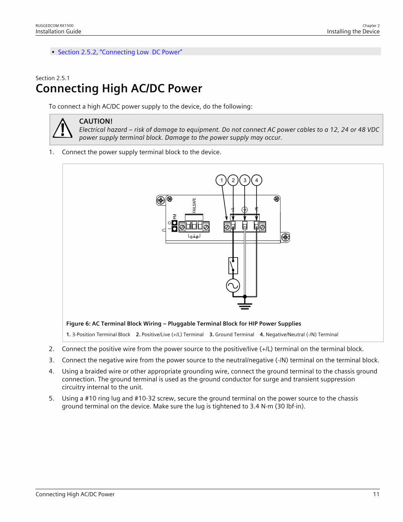
Connecting High AC/DC PowerTo connect a high AC/DC power supply to the device, do the following:
CAUTION!Electrical hazard – risk of damage to equipment. Do not connect AC power cables to a 12, 24 or 48 VDCpower supply terminal block. Damage to the power supply may occur.
1. Connect the power supply terminal block to the device.
1 2 3 4
Figure 6: AC Terminal Block Wiring – Pluggable Terminal Block for HIP Power Supplies
1. 3-Position Terminal Block 2. Positive/Live (+/L) Terminal 3. Ground Terminal 4. Negative/Neutral (-/N) Terminal
2. Connect the positive wire from the power source to the positive/live (+/L) terminal on the terminal block.3. Connect the negative wire from the power source to the neutral/negative (-/N) terminal on the terminal block.4. Using a braided wire or other appropriate grounding wire, connect the ground terminal to the chassis ground
connection. The ground terminal is used as the ground conductor for surge and transient suppressioncircuitry internal to the unit.
5. Using a #10 ring lug and #10-32 screw, secure the ground terminal on the power source to the chassisground terminal on the device. Make sure the lug is tightened to 3.4 N·m (30 lbf·in).

Chapter 2Installing the Device
RUGGEDCOM RX1500Installation Guide
12 Connecting Low DC Power
2
1
Figure 7: Chassis Ground Connection
1. #10-32 Screw 2. #10 Ring Lug
6. Install the safety cover over the terminal block.
Section 2.5.2
Connecting Low DC PowerTo connect a low DC power supply to the device, do the following:
CAUTION!Electrical hazard – risk of damage to equipment. Do not connect AC power cables to a 12, 24 or 48 VDCpower supply terminal block. Damage to the power supply may occur.
IMPORTANT!When connecting the device to a DC power source, make sure the source provides only positive voltage.
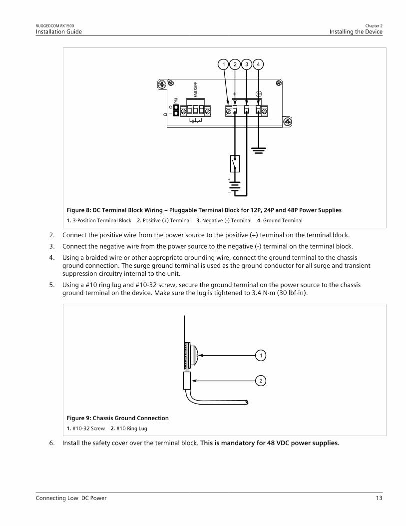
1. Connect the power supply terminal block to the device.
RUGGEDCOM RX1500Installation Guide
Chapter 2Installing the Device
Connecting Low DC Power 13
3 421
Figure 8: DC Terminal Block Wiring – Pluggable Terminal Block for 12P, 24P and 48P Power Supplies1. 3-Position Terminal Block 2. Positive (+) Terminal 3. Negative (-) Terminal 4. Ground Terminal
2. Connect the positive wire from the power source to the positive (+) terminal on the terminal block.3. Connect the negative wire from the power source to the negative (-) terminal on the terminal block.4. Using a braided wire or other appropriate grounding wire, connect the ground terminal to the chassis
ground connection. The surge ground terminal is used as the ground conductor for all surge and transientsuppression circuitry internal to the unit.
5. Using a #10 ring lug and #10-32 screw, secure the ground terminal on the power source to the chassisground terminal on the device. Make sure the lug is tightened to 3.4 N·m (30 lbf·in).
2
1
Figure 9: Chassis Ground Connection1. #10-32 Screw 2. #10 Ring Lug
6. Install the safety cover over the terminal block. This is mandatory for 48 VDC power supplies.
Chapter 2Installing the Device
RUGGEDCOM RX1500Installation Guide
14 Connecting Low DC Power

RUGGEDCOM RX1500Installation Guide
Chapter 3Device Management
Connecting to the Device 15
Device ManagementThis section describes how to connect to and manage the device.
CONTENTS• Section 3.1, “Connecting to the Device”• Section 3.2, “Configuring the Device”• Section 3.3, “Accessing the CompactFlash Card”
Section 3.1
Connecting to the DeviceThe following describes the various methods for accessing the RUGGEDCOM ROX II console and Web interfaceson the device. For more detailed instructions, refer to the RUGGEDCOM ROX II User Guide for the RUGGEDCOMRX1500.
Serial Console and Management PortsConnect a workstation directly to the serial console or management ports to access the boot-time control andRUGGEDCOM ROX II interfaces. The serial console port provides access to RUGGEDCOM ROX II's console interface,while the management port provides access to ROX II's console and Web interfaces.
IMPORTANT!The serial console and management (MGMT) ports are intended to be used only as temporaryconnections during initial configuration or troubleshooting.
The serial console port implements RS232 DCE (Data Communication Equipment) on a DB9 connector. Thefollowing is the pin-out for the port:
15
9 6
Figure 10: Serial DB9 Console Port
Pin Name Description
1 DCD Data Carrier Detect
2 RX Receive Data
3 TX Transmit Data
4 DTR Data Terminal Ready
5 GND Signal Ground
6 DSR Data Set Ready
7 RTS Request to Send
8 CTS Clear To Send
Chapter 3Device Management
RUGGEDCOM RX1500Installation Guide
16 Configuring the Device
Pin Name Description
9 Reserved (Do Not Connect)
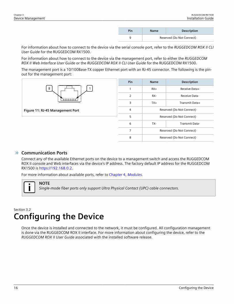
For information about how to connect to the device via the serial console port, refer to the RUGGEDCOM ROX II CLIUser Guide for the RUGGEDCOM RX1500.For information about how to connect to the device via the management port, refer to either the RUGGEDCOMROX II Web Interface User Guide or the RUGGEDCOM ROX II CLI User Guide for the RUGGEDCOM RX1500.The management port is a 10/100Base-TX copper Ethernet port with an RJ-45 connector. The following is the pin-out for the management port:
18
Figure 11: RJ-45 Management Port
Pin Name Description
1 RX+ Receive Data+
2 RX- Receive Data-
3 TX+ Transmit Data+
4 Reserved (Do Not Connect)
5 Reserved (Do Not Connect)
6 TX- Transmit Data-
7 Reserved (Do Not Connect)
8 Reserved (Do Not Connect)
Communication PortsConnect any of the available Ethernet ports on the device to a management switch and access the RUGGEDCOMROX II console and Web interfaces via the device's IP address. The factory default IP address for the RUGGEDCOMRX1500 is https://192.168.0.2.For more information about available ports, refer to Chapter 4, Modules.
NOTESingle-mode fiber ports only support Ultra Physical Contact (UPC) cable connectors.
Section 3.2
Configuring the DeviceOnce the device is installed and connected to the network, it must be configured. All configuration managementis done via the RUGGEDCOM ROX II interface. For more information about configuring the device, refer to theRUGGEDCOM ROX II User Guide associated with the installed software release.

RUGGEDCOM RX1500Installation Guide
Chapter 3Device Management
Accessing the CompactFlash Card 17
Section 3.3
Accessing the CompactFlash CardThe RUGGEDCOM RX1500 features a removable CompactFlash (CF) card that stores configuration files, firmware(active and backup versions), file-based feature keys and other system files.
CAUTION!Configuration hazard – risk of data corruption/loss. Do not remove or insert the CF card when thedevice is powered on.
The CF card should only be removed in the following scenarios:• The chassis is defective (with the exception of power and media modules)• The CF card is deemed defective or corrupt• The device is rendered non-functional due to a serious configuration error, data corruption, or hardware fault
CAUTION!Configuration hazard – risk of data corruption/loss. The following will void the warranty andpotentially result in configuration data corruption/loss:• Using a CF card not approved by Siemens for use with this device• Removing the CF card in any scenario other than those described in this section
Inserting the CF cardTo insert the CF card into the device, do the following:
IMPORTANT!The device should only be powered on when the CF card is present.
1. Make sure the device is powered down.2. Remove the CF card access panel.3. Insert the CF card into the slot until it is fully seated.

Chapter 3Device Management
RUGGEDCOM RX1500Installation Guide
18 Accessing the CompactFlash Card
2
1
Figure 12: Inserting the CF Card1. CompactFlash Card 2. Access Panel
4. Secure the CF card access panel to the chassis.
Removing the CF cardTo remove the CF card from the device, do the following:1. Make sure the device is powered down.2. Remove the CF card access panel.
3
2
1
Figure 13: Removing the CF Card1. Ejector Button 2. CompactFlash Card 3. Access Panel
3. Press the ejector button to the left of the CF card and then pull the card out.4. Secure the CF card access panel to the chassis.
RUGGEDCOM RX1500Installation Guide
Chapter 4Modules
Available Modules 19
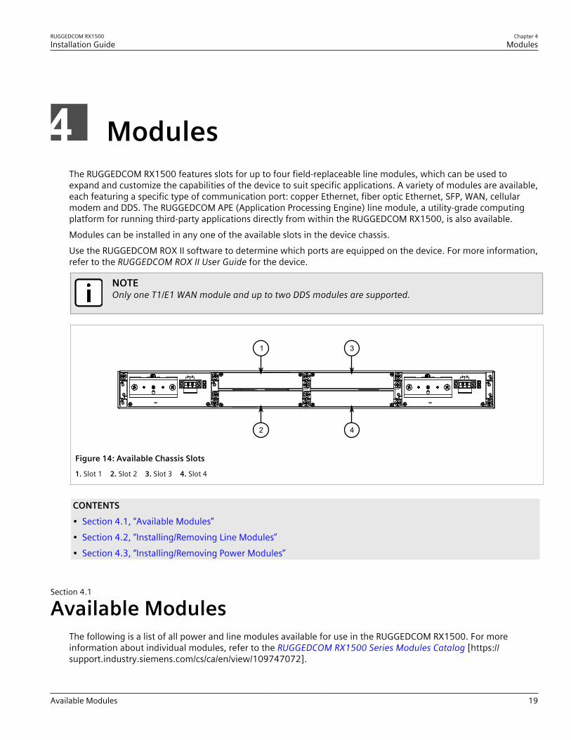
ModulesThe RUGGEDCOM RX1500 features slots for up to four field-replaceable line modules, which can be used toexpand and customize the capabilities of the device to suit specific applications. A variety of modules are available,each featuring a specific type of communication port: copper Ethernet, fiber optic Ethernet, SFP, WAN, cellularmodem and DDS. The RUGGEDCOM APE (Application Processing Engine) line module, a utility-grade computingplatform for running third-party applications directly from within the RUGGEDCOM RX1500, is also available.Modules can be installed in any one of the available slots in the device chassis.Use the RUGGEDCOM ROX II software to determine which ports are equipped on the device. For more information,refer to the RUGGEDCOM ROX II User Guide for the device.
NOTEOnly one T1/E1 WAN module and up to two DDS modules are supported.
1
2
3
4
Figure 14: Available Chassis Slots
1. Slot 1 2. Slot 2 3. Slot 3 4. Slot 4
CONTENTS• Section 4.1, “Available Modules”• Section 4.2, “Installing/Removing Line Modules”• Section 4.3, “Installing/Removing Power Modules”
Section 4.1
Available ModulesThe following is a list of all power and line modules available for use in the RUGGEDCOM RX1500. For moreinformation about individual modules, refer to the RUGGEDCOM RX1500 Series Modules Catalog [https://support.industry.siemens.com/cs/ca/en/view/109747072].
Chapter 4Modules
RUGGEDCOM RX1500Installation Guide
20 Available Modules
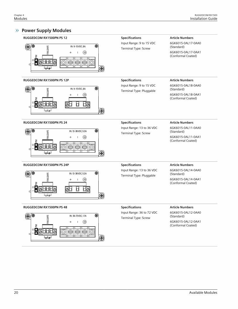
Power Supply ModulesRUGGEDCOM RX1500PN PS 12 Specifications
Input Range: 9 to 15 VDCTerminal Type: Screw
Article Numbers6GK6015-0AL17-0AA0(Standard)6GK6015-0AL17-0AA1(Conformal Coated)
RUGGEDCOM RX1500PN PS 12P SpecificationsInput Range: 9 to 15 VDCTerminal Type: Pluggable
Article Numbers6GK6015-0AL18-0AA0(Standard)6GK6015-0AL18-0AA1(Conformal Coated)
RUGGEDCOM RX1500PN PS 24 SpecificationsInput Range: 13 to 36 VDCTerminal Type: Screw
Article Numbers6GK6015-0AL11-0AA0(Standard)6GK6015-0AL11-0AA1(Conformal Coated)
RUGGEDCOM RX1500PN PS 24P SpecificationsInput Range: 13 to 36 VDCTerminal Type: Pluggable
Article Numbers6GK6015-0AL14-0AA0(Standard)6GK6015-0AL14-0AA1(Conformal Coated)
RUGGEDCOM RX1500PN PS 48 SpecificationsInput Range: 36 to 72 VDCTerminal Type: Screw
Article Numbers6GK6015-0AL12-0AA0(Standard)6GK6015-0AL12-0AA1(Conformal Coated)
RUGGEDCOM RX1500Installation Guide
Chapter 4Modules
Available Modules 21
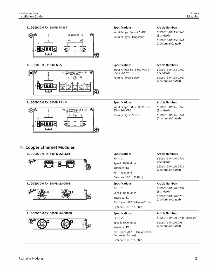
RUGGEDCOM RX1500PN PS 48P SpecificationsInput Range: 36 to 72 VDCTerminal Type: Pluggable
Article Numbers6GK6015-0AL15-0AA0(Standard)6GK6015-0AL15-0AA1(Conformal Coated)
RUGGEDCOM RX1500PN PS HI SpecificationsInput Range: 88 to 300 VDC or85 to 264 VACTerminal Type: Screw
Article Numbers6GK6015-0AL13-0AA0(Standard)6GK6015-0AL13-0AA1(Conformal Coated)
RUGGEDCOM RX1500PN PS HIP SpecificationsInput Range: 88 to 300 VDC or85 to 264 VACTerminal Type: Screw
Article Numbers6GK6015-0AL16-0AA0(Standard)6GK6015-0AL16-0AA1(Conformal Coated)
Copper Ethernet ModulesRUGGEDCOM RX1500PN LM CG01 Specifications
Ports: 2Speed: 1000 MbpsInterface: TXPort Type: RJ45Distance: 100 m (328 ft)
Article Numbers6GK6015-0AL20-0FC0(Standard)6GK6015-0AL20-0FC1(Conformal Coated)
RUGGEDCOM RX1500PN LM CG03 SpecificationsPorts: 2Speed: 1000 MbpsInterface: TXPort Type: M12 (8-Pin, A-Coded)Distance: 100 m (328 ft)
Article Numbers6GK6015-0AL20-0PB0(Standard)6GK6015-0AL20-0PB1(Conformal Coated)
RUGGEDCOM RX1500PN LM CG03B SpecificationsPorts: 2Speed: 1000 MbpsInterface: TXPort Type: M12 (8-Pin, A-Coded,Controlled Bypass)Distance: 100 m (328 ft)
Article Numbers6GK6015-0AL20-0PE0 (Standard)6GK6015-0AL20-0PE1(Conformal Coated)

Chapter 4Modules
RUGGEDCOM RX1500Installation Guide
22 Available Modules
RUGGEDCOM RX1500PN LM X CG04 SpecificationsPorts: 2Speed: 1000 MbpsInterface: TXPort Type: M12 (8-pin, X-Coded)Distance: 100 m (328 ft)
Article Numbers6GK6015-0AL20-0PH0(Standard)6GK6015-0AL20-0PH1(Conformal Coated)
RUGGEDCOM RX1500PN LM X CG04B SpecificationsPorts: 2Speed: 1000 MbpsInterface: TXPort Type: M12 (8-pin, X-Coded,Controlled Bypass)Distance: 100 m (328 ft)
Article Numbers6GK6015-0AL20-0PJ0 (Standard)6GK6015-0AL20-0PJ1(Conformal Coated)
RUGGEDCOM RX1500PN LM 4TX03 SpecificationsPorts: 4Speed: 100 MbpsInterface: TXPort Type: M12 (4-Pin, A-Coded)Distance: 100 m (328 ft)
Article Numbers6GK6015-0AL20-0PC0(Standard)6GK6015-0AL20-0PC1(Conformal Coated)
RUGGEDCOM RX1500PN LM 4TX03B SpecificationsPorts: 4Speed: 100 MbpsInterface: TXPort Type: M12 (8-Pin, A-Coded,Controlled Bypass)Distance: 100 m (328 ft)
Article Numbers6GK6015-0AL20-0PF0 (Standard)6GK6015-0AL20-0PF1(Conformal Coated)
RUGGEDCOM RX1500PN LM 4TX04 SpecificationsPorts: 4Speed: 100 MbpsInterface: TXPort Type: M12 (4-Pin, D-Coded)Distance: 100 m (328 ft)
Article Numbers6GK6015-0AL20-0PD0(Standard)6GK6015-0AL20-0PD1(Conformal Coated)
RUGGEDCOM RX1500PN LM 4TX04B SpecificationsPorts: 4Speed: 100 MbpsInterface: TXPort Type: M12 (4-Pin, A-Coded,Controlled Bypass)Distance: 100 m (328 ft)
Article Numbers6GK6015-0AL20-0PG0(Standard)6GK6015-0AL20-0PG1(Conformal Coated)
RUGGEDCOM RX1500PN LM 6TX01 SpecificationsPorts: 6Speed: 100 MbpsInterface: TXPort Type: RJ45Distance: 100 m (328 ft)
Article Numbers6GK6015-0AL20-0NB0(Standard)6GK6015-0AL20-0NB1(Conformal Coated)

RUGGEDCOM RX1500Installation Guide
Chapter 4Modules
Available Modules 23
Fiber Optic Ethernet ModulesRUGGEDCOM RX1500PN LM 4FX11 Specifications
Mode: MMSpeed: 100 MbpsInterface: FXWavelength: 1300 nmPorts: 4Port Type: LCDistance: 2 km (1.2 mi)
Article Numbers6GK6015-0AL20-0BC0(Standard)6GK6015-0AL20-0BC1(Conformal Coated)
RUGGEDCOM RX1500PN LM FL01 SpecificationsMode: MMSpeed: 10/100 MbpsInterface: FL/SXWavelength: 820 nmPorts: 3Port Type: STDistance: 2 km (1.2 mi)
Article Numbers6GK6015-0AL20-0BD0(Standard)6GK6015-0AL20-0BD1(Conformal Coated)
RUGGEDCOM RX1500PN LM FG03 SpecificationsMode: SMSpeed: 1000 MbpsInterface: LXWavelength: 820 nmPorts: 4Port Type: LCDistance: 10 km (6.2 mi)
Article Numbers6GK6015-0AL20-0EC0(Standard)6GK6015-0AL20-0EC1(Conformal Coated)
RUGGEDCOM RX1500PN LM FG50 SpecificationsSFP Sockets: 2Speed: 1000 Mbps
Article Numbers6GK6015-0AL20-0JB0 (Standard)6GK6015-0AL20-0JB1(Conformal Coated)
RUGGEDCOM RX1500PN LM FX50 SpecificationsSFP Sockets: 4Speed: 100 Mbps
Article Numbers6GK6015-0AL20-0JC0 (Standard)6GK6015-0AL20-0JC1(Conformal Coated)
RUGGEDCOM RX1500PN LM 6FX50 SpecificationsSFP Sockets: 6Speed: 100 Mbps
Article Numbers6GK6015-0AL20-0JD0 (Standard)6GK6015-0AL20-0JD1(Conformal Coated)

Chapter 4Modules
RUGGEDCOM RX1500Installation Guide
24 Available Modules
WAN ModulesRUGGEDCOM RX1500PN LM S01 Specifications
Standard: RS232/RS422/RS485Ports: 6Port Type: RJ45
Article Numbers (Standard)6GK6015-0AL20-0KB0(Standard)6GK6015-0AL20-0KB1(Conformal Coated)
RUGGEDCOM RX1500PN LM TC1 SpecificationsInterface: T1/E1Ports: 1Port Type: RJ48C
Article Numbers (Standard)6GK6015-0AL20-0MB0(Standard)6GK6015-0AL20-0MB1(Conformal Coated)
RUGGEDCOM RX1500PN LM TC2 SpecificationsInterface: T1/E1Ports: 2Port Type: RJ48C
Article Numbers (Standard)6GK6015-0AL20-0MC0(Standard)6GK6015-0AL20-0MC1(Conformal Coated)
RUGGEDCOM RX1500PN LM TC4 SpecificationsInterface: T1/E1Ports: 4Port Type: RJ48C
Article Numbers (Standard)6GK6015-0AL20-0MD0(Standard)6GK6015-0AL20-0MD1(Conformal Coated)
RUGGEDCOM RX1500PN LM E02 SpecificationsInterface: E1Ports: 2Port Type: BNC (75 Ω)
Article Numbers (Standard)6GK6015-0AL20-0HC0(Standard)6GK6015-0AL20-0HC1(Conformal Coated)
RUGGEDCOM RX1500PN LM D02 SpecificationsSpeed: 56 kbps (Master/Slave) or64 kbps (Slave)Ports: 1Port Type: RJ48S
Article Numbers (Standard)6GK6015-0AL20-0LB0 (Standard)6GK6015-0AL20-0LB1(Conformal Coated)
Cellular Modem ModulesRUGGEDCOM RX1500PN LM W11 Specifications
Services: GSM/EDGE/HSPA+Region: North America (AT&T)Port Type: 50 Ω SMAAntennas: 1 x GSM/EDGE/HSPA+,1 x Receive Diversity (Secondary)SIM: Dual Mini-SIM (2FF)
Article Numbers (Standard)6GK6015-0AL20-0WB0(Standard)6GK6015-0AL20-0WB1(Conformal Coated)
RUGGEDCOM RX1500PN LM W12 SpecificationsServices: GSM/EDGE/HSPA+Region: North America (AT&T),European Union, AustraliaPort Type: 50 Ω SMAAntennas: 2 x GSM/EDGE/HSPA+,2 x Receive Diversity (Secondary)
Article Numbers (Standard)6GK6015-0AL20-0WC0(Standard)6GK6015-0AL20-0WC1(Conformal Coated)

RUGGEDCOM RX1500Installation Guide
Chapter 4Modules
Available Modules 25
SIM: Dual Mini-SIM (2FF)
RUGGEDCOM RX1500PN LM W21 SpecificationsServices: EVDO Rev ARegion: North America (Verizon)Port Type: 50 Ω SMAAntennas: 1 x EVDO Rev A, 1 xReceive Diversity (Secondary)SIM: Dual Mini-SIM (2FF)
Article Numbers (Standard)6GK6015-0AL20-0WD0(Standard)6GK6015-0AL20-0WD1(Conformal Coated)
RUGGEDCOM RX1500PN LM W22 SpecificationsServices: EVDO Rev ARegion: North America (Verizon)Port Type: 50 Ω SMAAntennas: 2 x EVDO Rev A, 2 xReceive Diversity (Secondary)SIM: Dual Mini-SIM (2FF)
Article Numbers (Standard)6GK6015-0AL20-0WE0(Standard)6GK6015-0AL20-0WE1(Conformal Coated)
RUGGEDCOM RX1500PN LM W32 SpecificationsServices: EVDO Rev ARegion: North America (Verizon)Port Type: 50 Ω SMAAntennas: 1 x GSM/EDGE/HSPA+, 1 x EVDO Rev A, 2 x ReceiveDiversity (Secondary)SIM: Dual Mini-SIM (2FF)
Article Numbers (Standard)6GK6015-0AL20-0WF0(Standard)6GK6015-0AL20-0WF1(Conformal Coated)
RUGGEDCOM RX1500PN LM W41 SpecificationsServices: 4G LTE/HSPA+/HSDPA/HSUPA/DC-HSPA+/UMTS/WCDAM/EDGE/GPRS/GSM/GNSSRegion: European UnionPort Type: 50 Ω SMAAntennas: 1 x LTE Main, 1 x LTEMIMO, 1 x GPSSIM: Dual Mini-SIM (2FF)
Article Numbers (Standard)6GK6015-0AL20-0WG0(Standard)6GK6015-0AL20-0WG1(Conformal Coated)
RUGGEDCOM RX1500PN LM W51 SpecificationsServices: 4G LTE/HSPA+/HSDPA/HSUPA/DC-HSAP+/UMTS/WDCAM/EDGE/GPRS/GSM/CDMA/EVDO/GNSSRegion: North America (AT&T,Rogers, Bell, Telus)Port Type: 50 Ω SMAAntennas: 1 x LTE Main, 1 x LTEMIMO, 1 x GPSSIM: Dual Mini-SIM (2FF)
Article Numbers (Standard)6GK6015-0AL20-0WH0(Standard)6GK6015-0AL20-0WH1(Conformal Coated)
RUGGEDCOM RX1500PN LM W61 SpecificationsServices: 4G LTE/HSPA+/CDMA/EVDO/GPS/GNSSRegion: North America (Verizon,Sprint)Port Type: 50 Ω SMA
Article Numbers (Standard)6GK6015-0AL20-0WJ0(Standard)6GK6015-0AL20-0WJ1(Conformal Coated)
Chapter 4Modules
RUGGEDCOM RX1500Installation Guide
26 Available Modules
Antennas: 1 x LTE Main, 1 x LTEMIMO, 1 x GPSSIM: Dual Mini-SIM (2FF)
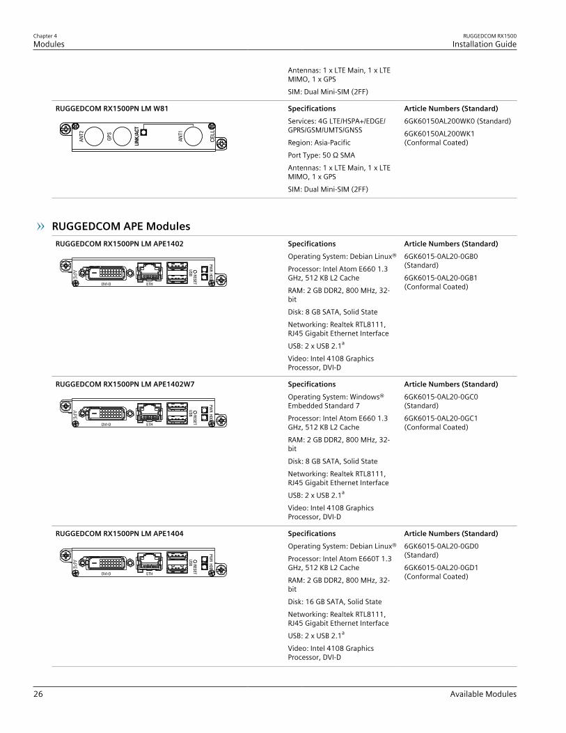
RUGGEDCOM RX1500PN LM W81 SpecificationsServices: 4G LTE/HSPA+/EDGE/GPRS/GSM/UMTS/GNSSRegion: Asia-PacificPort Type: 50 Ω SMAAntennas: 1 x LTE Main, 1 x LTEMIMO, 1 x GPSSIM: Dual Mini-SIM (2FF)
Article Numbers (Standard)6GK60150AL200WK0 (Standard)6GK60150AL200WK1(Conformal Coated)
RUGGEDCOM APE ModulesRUGGEDCOM RX1500PN LM APE1402 Specifications
Operating System: Debian Linux®Processor: Intel Atom E660 1.3GHz, 512 KB L2 CacheRAM: 2 GB DDR2, 800 MHz, 32-bitDisk: 8 GB SATA, Solid StateNetworking: Realtek RTL8111,RJ45 Gigabit Ethernet InterfaceUSB: 2 x USB 2.1a
Video: Intel 4108 GraphicsProcessor, DVI-D
Article Numbers (Standard)6GK6015-0AL20-0GB0(Standard)6GK6015-0AL20-0GB1(Conformal Coated)
RUGGEDCOM RX1500PN LM APE1402W7 SpecificationsOperating System: Windows®Embedded Standard 7Processor: Intel Atom E660 1.3GHz, 512 KB L2 CacheRAM: 2 GB DDR2, 800 MHz, 32-bitDisk: 8 GB SATA, Solid StateNetworking: Realtek RTL8111,RJ45 Gigabit Ethernet InterfaceUSB: 2 x USB 2.1a
Video: Intel 4108 GraphicsProcessor, DVI-D
Article Numbers (Standard)6GK6015-0AL20-0GC0(Standard)6GK6015-0AL20-0GC1(Conformal Coated)
RUGGEDCOM RX1500PN LM APE1404 SpecificationsOperating System: Debian Linux®Processor: Intel Atom E660T 1.3GHz, 512 KB L2 CacheRAM: 2 GB DDR2, 800 MHz, 32-bitDisk: 16 GB SATA, Solid StateNetworking: Realtek RTL8111,RJ45 Gigabit Ethernet InterfaceUSB: 2 x USB 2.1a
Video: Intel 4108 GraphicsProcessor, DVI-D
Article Numbers (Standard)6GK6015-0AL20-0GD0(Standard)6GK6015-0AL20-0GD1(Conformal Coated)

RUGGEDCOM RX1500Installation Guide
Chapter 4Modules
Available Modules 27
RUGGEDCOM RX1500PN LM APE1404W7 SpecificationsOperating System: Windows®Embedded Standard 7Processor: Intel Atom E660T 1.3GHz, 512 KB L2 CacheRAM: 2 GB DDR2, 800 MHz, 32-bitDisk: 16 GB SATA, Solid StateNetworking: Realtek RTL8111,RJ45 Gigabit Ethernet InterfaceUSB: 2 x USB 2.1a
Video: Intel 4108 GraphicsProcessor, DVI-D
Article Numbers (Standard)6GK6015-0AL20-0GE0(Standard)6GK6015-0AL20-0GE1(Conformal Coated)
RUGGEDCOM RX1500PN LM APE1404CKP SpecificationsOperating System: Check PointGAiA™ OSProcessor: Intel Atom E660T 1.3GHz, 512 KB L2 CacheRAM: 2 GB DDR2, 800 MHz, 32-bitDisk: 16 GB SATA, Solid StateNetworking: Realtek RTL8111,RJ45 Gigabit Ethernet InterfaceUSB: 2 x USB 2.1a
Video: Intel 4108 GraphicsProcessor, DVI-D
Article Numbers (Standard)6GK6015-0AL20-0GF0(Standard)6GK6015-0AL20-0GF1(Conformal Coated)
a Maximum combined USB device power consumption is 500 mA at 5 V.
Blank ModulesRUGGEDCOM RX1500PN PS XXP Specifications
—Article Numbers6GK6015-0AL10-0AA0(Standard)6GK6015-0AL10-0AA1(Conformal Coated)
RUGGEDCOM RX1500PN LM Blank Specifications—
Article Numbers6GK6015-0AL20-0AA0(Standard)6GK6015-0AL20-0AA1(Conformal Coated)
Chapter 4Modules
RUGGEDCOM RX1500Installation Guide
28 Installing/Removing Line Modules
Section 4.2
Installing/Removing Line ModulesUpon installing a new line module in the device, all features associated with the module are available inRUGGEDCOM ROX II. For more information, refer to the RUGGEDCOM ROX II User Guide for the RUGGEDCOMRX1500.Once a line module is removed, all the features associated with the module are hidden or disabled in RUGGEDCOMROX II.
CAUTION!Electrical hazard – risk of power failure. Do not install more than two RUGGEDCOM APE modules.Installing more than two of this type of module can lead to power fluctuations and irregular shutdowns.
IMPORTANT!Only one WAN line module is supported per chassis.
CAUTION!Contamination hazard – risk of equipment damage. Prevent the ingress of water, dirts and other debristhat may lead to premature equipment failure. Always make sure slots are not left empty and openports are protected with plugs or covers.
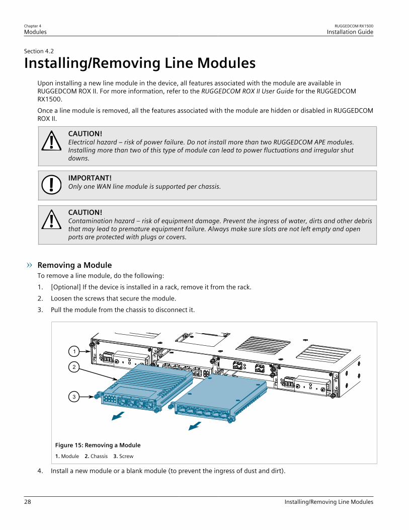
Removing a ModuleTo remove a line module, do the following:1. [Optional] If the device is installed in a rack, remove it from the rack.2. Loosen the screws that secure the module.3. Pull the module from the chassis to disconnect it.
1
2
3
Figure 15: Removing a Module
1. Module 2. Chassis 3. Screw
4. Install a new module or a blank module (to prevent the ingress of dust and dirt).
RUGGEDCOM RX1500Installation Guide
Chapter 4Modules
Installing/Removing Power Modules 29
5. [Optional] If necessary, install the device in the rack.
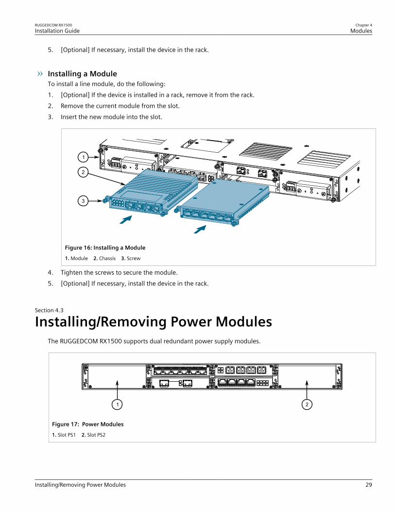
Installing a ModuleTo install a line module, do the following:1. [Optional] If the device is installed in a rack, remove it from the rack.2. Remove the current module from the slot.3. Insert the new module into the slot.
1
2
3
Figure 16: Installing a Module
1. Module 2. Chassis 3. Screw
4. Tighten the screws to secure the module.5. [Optional] If necessary, install the device in the rack.
Section 4.3
Installing/Removing Power ModulesThe RUGGEDCOM RX1500 supports dual redundant power supply modules.
1 2
Figure 17: Power Modules
1. Slot PS1 2. Slot PS2
Chapter 4Modules
RUGGEDCOM RX1500Installation Guide
30 Installing/Removing Power Modules
CAUTION!Contamination hazard – risk of equipment damage. Prevent the ingress of water, dirts and other debristhat may lead to premature equipment failure. Always make sure slots are not left empty.
NOTEPower modules are hot swappable. When installing/removing a power module, it is not necessary toturn off power to the redundant power module.
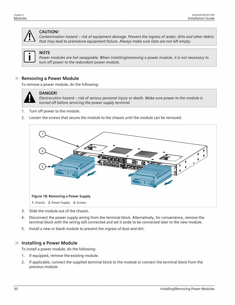
Removing a Power ModuleTo remove a power module, do the following:
DANGER!Electrocution hazard – risk of serious personal injury or death. Make sure power to the module isturned off before servicing the power supply terminal.
1. Turn off power to the module.2. Loosen the screws that secure the module to the chassis until the module can be removed.
3
2
1
Figure 18: Removing a Power Supply
1. Chassis 2. Power Supply 3. Screws
3. Slide the module out of the chassis.4. Disconnect the power supply wiring from the terminal block. Alternatively, for convenience, remove the
terminal block with the wiring still connected and set it aside to be connected later to the new module.5. Install a new or blank module to prevent the ingress of dust and dirt.
Installing a Power ModuleTo install a power module, do the following:1. If equipped, remove the existing module.2. If applicable, connect the supplied terminal block to the module or connect the terminal block from the
previous module.

RUGGEDCOM RX1500Installation Guide
Chapter 4Modules
Installing/Removing Power Modules 31
3. Confirm or connect the wiring from the power supply to the module. For more information, refer toSection 2.5, “Connecting Power”.
4. Insert the module into the empty slot.
3
2
1
Figure 19: Installing a Power Module1. Chassis 2. Power Module 3. Screws
5. Hand-tighten the screws to secure the power module to the chassis.6. Turn on power to the device and confirm the module is receiving and supplying power. This is indicated by
the LEDs on the module.
LED State Description
O Green The module is supplying power
I Green The module is receiving power
Chapter 4Modules
RUGGEDCOM RX1500Installation Guide
32 Installing/Removing Power Modules
RUGGEDCOM RX1500Installation Guide
Chapter 5Technical Specifications
Power Supply Specifications 33
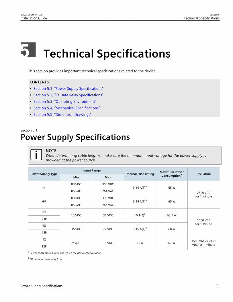
Technical SpecificationsThis section provides important technical specifications related to the device.
CONTENTS• Section 5.1, “Power Supply Specifications”• Section 5.2, “Failsafe Relay Specifications”• Section 5.3, “Operating Environment”• Section 5.4, “Mechanical Specifications”• Section 5.5, “Dimension Drawings”
Section 5.1
Power Supply SpecificationsNOTEWhen determining cable lengths, make sure the minimum input voltage for the power supply isprovided at the power source.
Input RangePower Supply Type
Min MaxInternal Fuse Rating Maximum Power
Consumptiona Insulation
88 VDC 300 VDCHI
85 VAC 264 VAC3.15 A(T)b 65 W
88 VDC 300 VDCHIP
85 VAC 264 VAC3.15 A(T)b 65 W
2800 VDCfor 1 minute
24
24P13 VDC 36 VDC 10 A(T)b 63.5 W
48
48P36 VDC 72 VDC 3.15 A(T)b 60 W
1500 VDCfor 1 minute
12
12P9 VDC 15 VDC 12 A 67 W 1500 VAC or 2121
VDC for 1 minute
a Power consumption varies based on the device configuration.
b (T) denotes time-delay fuse.
Chapter 5Technical Specifications
RUGGEDCOM RX1500Installation Guide
34 Failsafe Relay Specifications
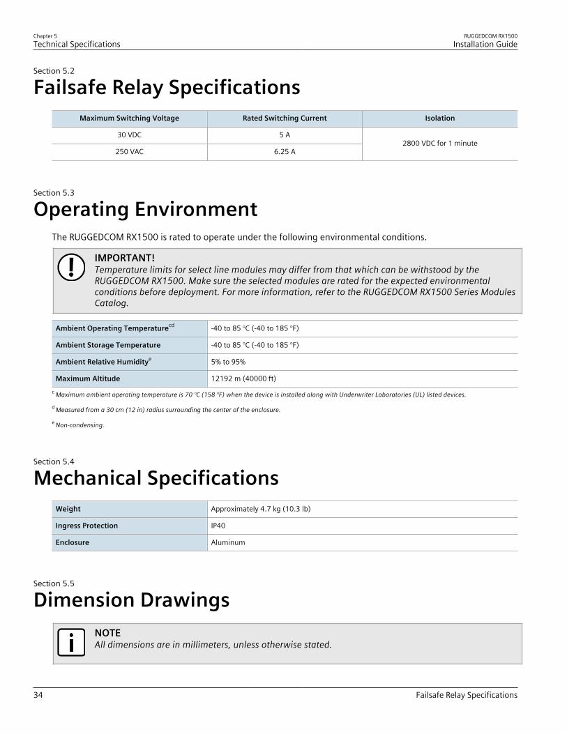
Section 5.2
Failsafe Relay SpecificationsMaximum Switching Voltage Rated Switching Current Isolation
30 VDC 5 A
250 VAC 6.25 A2800 VDC for 1 minute
Section 5.3
Operating EnvironmentThe RUGGEDCOM RX1500 is rated to operate under the following environmental conditions.
IMPORTANT!Temperature limits for select line modules may differ from that which can be withstood by theRUGGEDCOM RX1500. Make sure the selected modules are rated for the expected environmentalconditions before deployment. For more information, refer to the RUGGEDCOM RX1500 Series ModulesCatalog.
Ambient Operating Temperaturecd -40 to 85 °C (-40 to 185 °F)
Ambient Storage Temperature -40 to 85 °C (-40 to 185 °F)
Ambient Relative Humiditye 5% to 95%
Maximum Altitude 12192 m (40000 ft)c Maximum ambient operating temperature is 70 °C (158 °F) when the device is installed along with Underwriter Laboratories (UL) listed devices.
d Measured from a 30 cm (12 in) radius surrounding the center of the enclosure.
e Non-condensing.
Section 5.4
Mechanical SpecificationsWeight Approximately 4.7 kg (10.3 lb)
Ingress Protection IP40
Enclosure Aluminum
Section 5.5
Dimension DrawingsNOTEAll dimensions are in millimeters, unless otherwise stated.
RUGGEDCOM RX1500Installation Guide
Chapter 5Technical Specifications
Dimension Drawings 35
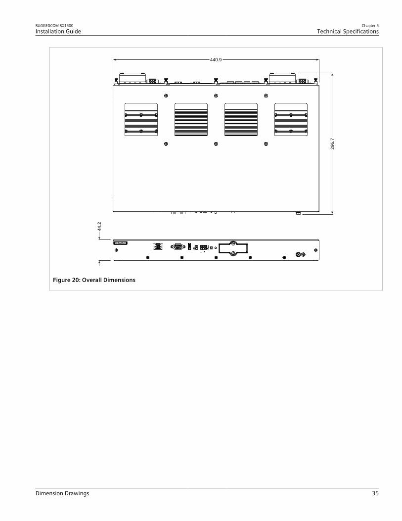
44.2
440.9
296.
7
Figure 20: Overall Dimensions

Chapter 5Technical Specifications
RUGGEDCOM RX1500Installation Guide
36 Dimension Drawings
31.8
463.8
4.7
6.35
5.1.
1
28.7
161.
0 212.
1
11.7
21.1
Figure 21: Rack Mount Dimensions
160.0
489.2 51.6
479.0
134.6
68.8
21.111.7
29.0
51.1
161.0 212.1
Figure 22: Panel and Din Rail Mount Dimensions
RUGGEDCOM RX1500Installation Guide
Chapter 5Technical Specifications
Dimension Drawings 37
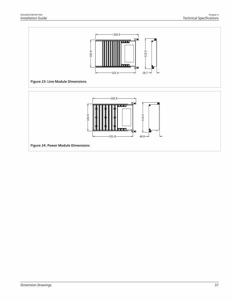
19.7151.4
102.
9
113.
3
162.5
Figure 23: Line Module Dimensions
162.5
40.6151.8
102.
9
113.
4Figure 24: Power Module Dimensions

Chapter 5Technical Specifications
RUGGEDCOM RX1500Installation Guide
38 Dimension Drawings
RUGGEDCOM RX1500Installation Guide
Chapter 6Certification
Approvals 39
CertificationThe RUGGEDCOM RX1500 device has been thoroughly tested to guarantee its conformance with recognizedstandards and has received approval from recognized regulatory agencies.
NOTECertifications related to individual modules are detailed in the RUGGEDCOM Modules Catalog for thedevice available online.
CONTENTS• Section 6.1, “Approvals”• Section 6.2, “EMC and Environmental Type Tests”
Section 6.1
ApprovalsThis section details the standards to which the RUGGEDCOM RX1500 complies.
CONTENTS• Section 6.1.1, “TÜV SÜD”• Section 6.1.2, “European Union (EU)”• Section 6.1.3, “FCC”• Section 6.1.4, “FDA/CDRH”• Section 6.1.5, “ISED”• Section 6.1.6, “ACMA”• Section 6.1.7, “RoHS”• Section 6.1.8, “Other Approvals”
Section 6.1.1
TÜV SÜDThis device is certified by TÜV SÜD to meet the requirements of the following standards:• CAN/CSA-C22.2 NO. 60950-1-07 (R2012)
Information Technology Equipment – Safety – Part 1: General Requirements (Bi-National standard, with UL60950-1)

Chapter 6Certification
RUGGEDCOM RX1500Installation Guide
40 European Union (EU)
• UL 60950-1Information Technology Equipment – Safety – Part 1: General Requirements)
Section 6.1.2
European Union (EU)This device is declared by Siemens Canada Ltd to comply with essential requirements and other relevant provisionsof the following EU directives:• Directive 2014/30/EU
Directive 2014/30/EU of the European Parliament and of the Council of 26 February 2014 on the harmonisationof the laws of the Member States relating to electromagnetic compatibility (recast) Text with EEA relevance
• Directive 2014/35/EUDirective 2014/35/EU of the European Parliament and of the Council of 26 February 2014 on the harmonisationof the laws of the Member States relating to the making available on the market of electrical equipmentdesigned for use within certain voltage limits Text with EEA relevance
• Directive 2011/65/EUDirective 2011/65/EU of the European Parliament and of the Council of 8 June 2011 on the restriction of the useof certain hazardous substances in electrical and electronic equipment Text with EEA relevance
• Directive 1999/5/ECDirective 1999/5/EC of the European Parliament and of the Council of 9 March 1999 on radio equipment andtelecommunications terminal equipment and the mutual recognition of their conformity
• EN 60950-1Information Technology Equipment – Safety – Part 1: General Requirements
• EN 61000-3-2Electromagnetic compatibility (EMC) – Part 3-2: Limits – Limits for harmonic current emissions (equipmentinput current ≤ 16 A per phase)
• EN 61000-3-3Electromagnetic compatibility (EMC) – Part 3-3: Limits – Limitation of voltage changes, voltage fluctuations andflicker in public low-voltage supply systems, for equipment with rated current ≤16 A per phase and not subjectto conditional connection
• EN 61000-6-2Electromagnetic Compatibility (EMC) – Part 6-2: Generic Standards – Immunity for Industrial Environments
• EN 60825-1Safety of Laser Products – Equipment Classification and Requirements
• EN 50581Technical Documentation for the Assessment of Electrical and Electronic Products with Respect to the Restrictionof Hazardous Substances
• EN 55022Information Technology Equipment – Radio Disturbance Characteristics – Limits and Methods of Measurement
The device is marked with a CE marking and notified body number, and can be used throughout the Europeancommunity.
0680
RUGGEDCOM RX1500Installation Guide
Chapter 6Certification
FCC 41
A copy of the CE Declaration of Conformity is available from Siemens Canada Ltd. For contact information, refer to“Contacting Siemens”.
Section 6.1.3
FCCThis device has been tested and found to comply with the limits for a Class A digital device, pursuant to Part 15 ofthe FCC Rules. These limits are designed to provide reasonable protection against harmful interference when theequipment is operated in a commercial environment.This device generates, uses and can radiate radio frequency energy and, if not installed and used in accordancewith the instruction manual, may cause harmful interference to radio communications. Operation of thisequipment in a residential area is likely to cause harmful interference in which case users will be required tocorrect the interference at their own expense.
IMPORTANT!Changes or modifications not expressly approved by the party responsible for compliance could voidthe user's authority to operate this device.
Section 6.1.4
FDA/CDRHThis device meets the requirements of the following U.S. Food and Drug Administration (FDA) standard:• Title 21 Code of Federal Regulations (CFR) – Chapter I – Sub-chapter J – Radiological Health
Section 6.1.5
ISEDThis device is declared by Siemens Canada Ltd to meet the requirements of the following ISED (Innovation Scienceand Economic Development Canada) standard:• CAN ICES-3 (A)/NMB-3 (A)
Section 6.1.6
ACMAThis device meets the requirements of the following Australian Communications and Media Authority (ACMA)standards under certificate ABN 98 004 347 880:• Radiocommunications (Compliance Labelling – Devices) Notice 2014 made under Section 182 of the
Radiocommunications Act 1992• Radiocommunications Labelling (Electromagnetic Compatibility) Notice 2008 made under Section 182 of the
Radiocommunications Act 1992• Radiocommunications (Compliance Labelling – Electromagnetic Radiation) Notice 2003 made under Section
182 of the Radiocommunications Act 1992

Chapter 6Certification
RUGGEDCOM RX1500Installation Guide
42 RoHS
• Telecommunications Labelling (Customer Equipment and Customer Cabling) Notice 2001 made under Section407 of the Telecommunication Act 1997
The device is marked with an RCM symbol to indicate compliance when sold in the Australian region.
A copy of the Declaration of Conformity is available via Siemens Industry Online Support at https://support.industry.siemens.com/cs/ww/en/view/89855782.
Section 6.1.7
RoHSThis device is declared by Siemens Canada Ltd to meet the requirements of the following RoHS (Restriction ofHazardous Substances) directives for the restricted use of certain hazardous substances in electrical and electronicequipment:• China RoHS 2
Administrative Measure on the Control of Pollution Caused by Electronic Information ProductsA copy of the Material Declaration is available online at https://support.industry.siemens.com/cs/ww/en/view/109738831.
Section 6.1.8
Other ApprovalsThis device meets the requirements of the following additional standards:• IEEE 1613
IEEE Standard Environmental and Testing Requirements for Communications Networking Devices in ElectricPower Substations
• IEC 61000-6-2Electromagnetic Compatibility (EMC) – Part 6-2: Generic Standards – Immunity for Industrial Environments
• IEC 61850-3Communication Networks and Systems in Substations – Part 3: General Requirements
Section 6.2
EMC and Environmental Type TestsThe RUGGEDCOM RX1500 has passed the following Electromagnetic Compatibility (EMC) and environmental tests.
RUGGEDCOM RX1500Installation Guide
Chapter 6Certification
EMC and Environmental Type Tests 43
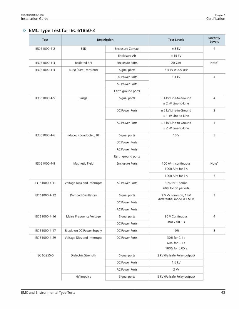
EMC Type Test for IEC 61850-3
Test Description Test Levels SeverityLevels
Enclosure Contact ± 8 kVIEC 61000-4-2 ESD
Enclosure Air ± 15 kV
4
IEC 61000-4-3 Radiated RFI Enclosure Ports 20 V/m
Signal ports ± 4 kV @ 2.5 kHz
Notea
DC Power Ports
AC Power Ports
IEC 61000-4-4 Burst (Fast Transient)
Earth ground ports
± 4 kV 4
Signal ports ± 4 kV Line-to-Ground± 2 kV Line-to-Line
4
DC Power Ports ± 2 kV Line-to-Ground± 1 kV Line-to-Line
3
IEC 61000-4-5 Surge
AC Power Ports ± 4 kV Line-to-Ground± 2 kV Line-to-Line
4
Signal ports
DC Power Ports
AC Power Ports
IEC 61000-4-6 Induced (Conducted) RFI
Earth ground ports
10 V 3
100 A/m, continuous1000 A/m for 1 s
NoteaIEC 61000-4-8 Magnetic Field Enclosure Ports
1000 A/m for 1 s 5
IEC 61000-4-11 Voltage Dips and Interrupts AC Power Ports 30% for 1 period60% for 50 periods
Signal ports
DC Power Ports
IEC 61000-4-12 Damped Oscillatory
AC Power Ports
2.5 kV common, 1 kVdifferential mode @1 MHz
3
Signal portsIEC 61000-4-16 Mains Frequency Voltage
DC Power Ports
30 V Continuous300 V for 1 s
4
IEC 61000-4-17 Ripple on DC Power Supply DC Power Ports 10% 3
IEC 61000-4-29 Voltage Dips and Interrupts DC Power Ports 30% for 0.1 s60% for 0.1 s
100% for 0.05 s
Signal ports 2 kV (Failsafe Relay output)
DC Power Ports 1.5 kV
Dielectric Strength
AC Power Ports 2 kV
IEC 60255-5
HV Impulse Signal ports 5 kV (Failsafe Relay output)
Chapter 6Certification
RUGGEDCOM RX1500Installation Guide
44 EMC and Environmental Type Tests
Test Description Test Levels SeverityLevels
DC Power Ports
AC Power Ports
5 kV
a Siemens-specified severity levels
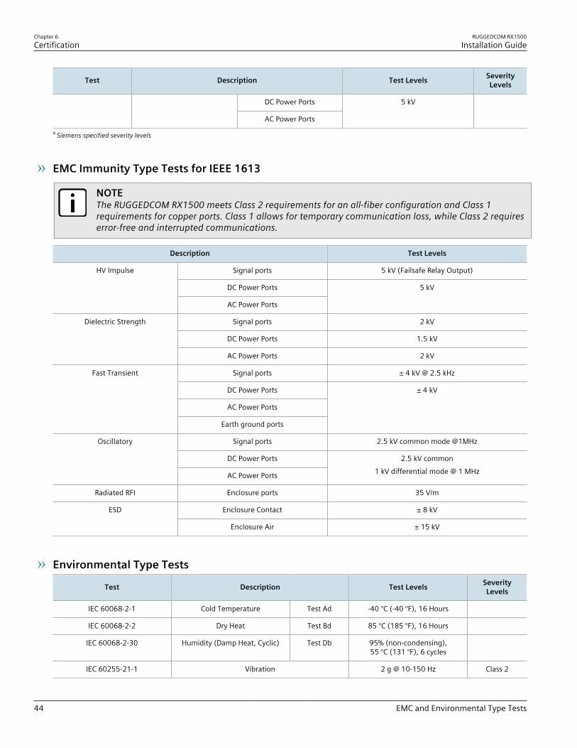
EMC Immunity Type Tests for IEEE 1613
NOTEThe RUGGEDCOM RX1500 meets Class 2 requirements for an all-fiber configuration and Class 1requirements for copper ports. Class 1 allows for temporary communication loss, while Class 2 requireserror-free and interrupted communications.
Description Test Levels
Signal ports 5 kV (Failsafe Relay Output)
DC Power Ports
HV Impulse
AC Power Ports
5 kV
Signal ports 2 kV
DC Power Ports 1.5 kV
Dielectric Strength
AC Power Ports 2 kV
Signal ports ± 4 kV @ 2.5 kHz
DC Power Ports
AC Power Ports
Fast Transient
Earth ground ports
± 4 kV
Signal ports 2.5 kV common mode @1MHz
DC Power Ports
Oscillatory
AC Power Ports
2.5 kV common1 kV differential mode @ 1 MHz
Radiated RFI Enclosure ports 35 V/m
Enclosure Contact ± 8 kVESD
Enclosure Air ± 15 kV
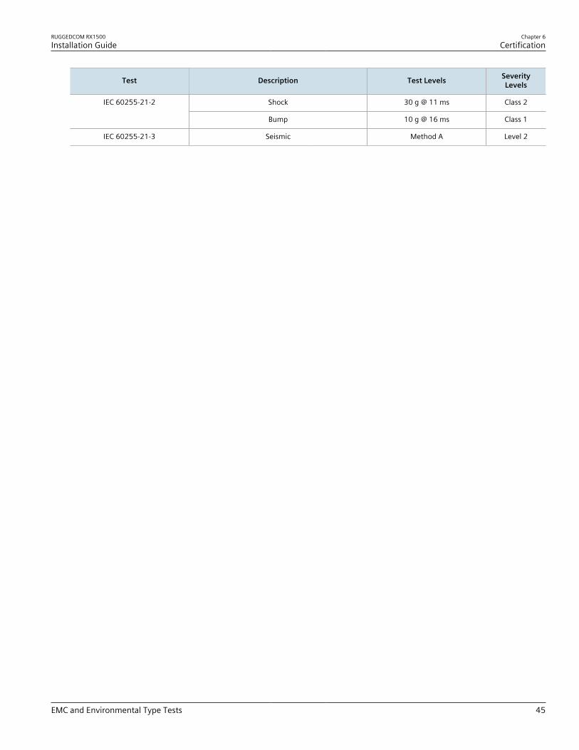
Environmental Type Tests
Test Description Test Levels SeverityLevels
IEC 60068-2-1 Cold Temperature Test Ad -40 °C (-40 °F), 16 Hours
IEC 60068-2-2 Dry Heat Test Bd 85 °C (185 °F), 16 Hours
IEC 60068-2-30 Humidity (Damp Heat, Cyclic) Test Db 95% (non-condensing),55 °C (131 °F), 6 cycles
IEC 60255-21-1 Vibration 2 g @ 10-150 Hz Class 2
RUGGEDCOM RX1500Installation Guide
Chapter 6Certification
EMC and Environmental Type Tests 45
Test Description Test Levels SeverityLevels
Shock 30 g @ 11 ms Class 2IEC 60255-21-2
Bump 10 g @ 16 ms Class 1
IEC 60255-21-3 Seismic Method A Level 2

Chapter 6Certification
RUGGEDCOM RX1500Installation Guide
46 EMC and Environmental Type Tests