introduction - dmaportal.files.wordpress.com · 01.02.2017 · has the same definition as in the...
TRANSCRIPT

1
.1 cargo ships;
.2 cargo ships car
.3 passenger ship
.4 fishing vessels
.5 special purpos
.6 offshore suppl
.7 mobile offsho
.8 pontoons; and
.9 cargo ships ca
INTRODUCTION 1 Purpose
1.1 The purpose of the Standard is to present mandatory and recommendatory stability criteria and other measures for ensuring the safe operation of ships, to minimize the risk to such ships, to the personnel on board and to the environment. This introduction and Chapter 1 of the Standard address the mandatory criteria and Chapter 4 contains recommendations and additional guidelines.
1.2 This Standard contains intact stability criteria for the following types of ships and other marine vehicles of 24 m in length and above trading in international voyage, unless otherwise stated:
rying timber deck cargoes;
s;
;
e ships;
y vessels;
re drilling units;
rrying containers on deck and containerships.
1.3 Administration may impose additional requirements regarding the design aspects of ships of novel design or ships not otherwise covered by the Standard.
2 Definitions
For the purpose of this item, the definitions given hereunder shall apply. For terms used, but not defined in this Standard, the definitions as given in the 1974 SOLAS Convention, as amended, shall apply.
2.1 Administration means the Department of Marine Administration, the Government of the Republic of the Union of Myanmar. The State whose flag the ship is entitled to fly.
2.2 Passenger ship is a ship which carries more than twelve passengers as defined in regulation I/2 of the 1974 SOLAS Convention, as amended.
2.3 Cargo ship is any ship which is not a passenger ship, a ship of war and troopship, a ship which is not propelled by mechanical means, a wooden ship of primitive build, a fishing vessel or a mobile offshore drilling unit.
2.4 Oil tanker means a ship constructed or adapted primarily to carry oil in bulk in its cargo spaces and includes combination carriers and any chemical tanker as defined in Annex II of the MARPOL Convention when it is carrying a cargo or part cargo of oil in bulk.
2.4.1 Combination carrier means a ship designed to carry either oil or solid cargoes in bulk.
2.4.2 Crude oil tanker means an oil tanker engaged in the trade of carrying crude oil.
2.4.3 Product carrier means an oil tanker engaged in the trade of carrying oil other than
2
crude oil. 2.5 Fishing vessel is a vessel used for catching fish, whales, seals, walrus or other living resources of the sea.
2.6 Special purpose ship has the same definition as in the Code of Safety for Special Purpose Ships, 2008 (IMO resolution MSC.266(84)).
2.7 Offshore supply vessel means a vessel which is engaged primarily in the transport of stores, materials and equipment to offshore installations and designed with accommodation and bridge erections in the forward part of the vessel and an exposed cargo deck in the after part for the handling of cargo at sea.
2.8 Mobile offshore drilling unit (MODU or unit) is a ship capable of engaging in drilling operations for the exploration or exploitation of resources beneath the sea-bed such as liquid or gaseous hydrocarbons, sulphur or salt.
2.8.1 Column-stabilized unit is a unit with the main deck connected to the underwater hull or footings by columns or caissons.
2.8.2 Surface unit is a unit with a ship- or barge-type displacement hull of single or multiple hull construction intended for operation in the floating condition.
2.8.3 Self-elevating unit is a unit with moveable legs capable of raising its hull above the surface of the sea.
2.8.4 Coastal State means the Government of the State exercising administrative control over the drilling operations of the unit.
2.8.5 Mode of operation means a condition or manner in which a unit may operate or function while on location or in transit. The modes of operation of a unit include the following:
.1 operating conditions means conditions wherein a unit is on location for the purpose of conducting drilling operations, and combined environmental and operational loadings are within the appropriate design limits established for such operations. The unit may be either afloat or supported on the sea-bed, as applicable;
.2 severe storm conditions means conditions wherein a unit may be subjected to the most severe environmental loadings for which the unit is designed. Drilling operations are assumed to have been discontinued due to the severity of the environmental loadings, the unit may be either afloat or supported on the sea-bed, as applicable; and
.3 transit conditions means conditions wherein a unit is moving from one geographical location to another.
2.9 High-speed craft (HSC) is a craft capable of a maximum speed, in metres per second (m/s), equal to or exceeding:
3.7 * ∇0.1667
where: ∇ = displacement corresponding to the design waterline (m3). 2.10 Containership means a ship which is used primarily for the transport of marine containers.
2.11 Freeboard is the distance between the assigned load line and freeboard deck .
2.12 Length of ship. The length shall be taken as 96% of the total length on a waterline at 85% of the least moulded depth measured from the top of the keel, or as the length from the fore side of the stem to the axis of the rudder stock on the waterline, if that be greater. In ships designed
3
with a rake of keel the waterline on which this length is measured shall be parallel to the designed waterline.
2.13 Moulded breadth is the maximum breadth of the ship measured amidships to the moulded line of the frame in a ship with a metal shell and to the outer surface of the hull in a ship with a shell of any other material.
2.14 Moulded depth is the vertical distance measured from the top of the keel to the top of the freeboard deck beam at side. In wood and composite ships, the distance is measured from the lower edge of the keel rabbet. Where the form at the lower part of the midship section is of a hollow character, or where thick garboards are fitted, the distance is measured from the point where the line of the flat of the bottom continued inwards cuts the side of the keel. In ships having rounded gunwales, the moulded depth shall be measured to the point of intersection of the moulded lines of the deck and side shell plating, the lines extending as though the gunwale were of angular design. Where the freeboard deck is stepped and the raised part of the deck extends over the point at which the moulded depth is to be determined, the moulded depth shall be measured to a line of reference extending from the lower part of the deck along a line parallel with the raised part.
2.15 Near-coastal voyage means a voyage in the vicinity of the coast of a State as defined by the Administration of that State.
2.16 Pontoon is considered to be normally:
.1 non self-propelled;
.2 unmanned;
.3 carrying only deck cargo;
.4 having a block coefficient of 0.9 or greater;
.5 having a breadth/depth ratio of greater than 3; and
.6 having no hatchways in the deck except small manholes closed with gasketed
covers.
2.17 Timber means sawn wood or lumber, cants, logs, poles, pulpwood and all other types of timber in loose or packaged forms. The term does not include wood pulp or similar cargo.
2.18 Timber deck cargo means a cargo of timber carried on an uncovered part of a freeboard or superstructure deck. The term does not include wood pulp or similar cargo.*
2.19 Timber load line means a special load line assigned to ships complying with certain conditions related to their construction set out in the International Convention on Load Lines and used when the cargo complies with the stowage and securing conditions of the Standard of Safe Practice for Ships Carrying Timber Deck Cargoes, 1991 (resolution A.715(17)).
2.20 Certification of the inclining test weights is the verification of the weight marked on a test weight. Test weights shall be certified using a certificated scale. The weighing shall be performed close enough in time to the inclining test to ensure the measured weight is accurate.
2.21 Draught is the vertical distance from the moulded baseline to the waterline.
* Refer to regulation 42(1) of the International Convention on Load Lines, 1966 or the Protocol of 1988 as amended, as applicable.

4
2.22 The inclining test involves moving a series of known weights, normally in the transverse direction, and then measuring the resulting change in the equilibrium heel angle of the ship. By using this information and applying basic naval architecture principles, the ship’s vertical centre of gravity (VCG) is determined.
2.23 Lightship condition is a ship complete in all respects, but without consumables, stores, cargo, crew and effects, and without any liquids on board except that machinery and piping fluids, such as lubricants and hydraulics, are at operating levels.
2.24 A lightweight survey involves taking an audit of all items which shall be added, deducted or relocated on the ship at the time of the inclining test so that the observed condition of the ship can be adjusted to the lightship condition. The mass, longitudinal, transverse and vertical location of each item shall be accurately determined and recorded. Using this information, the static waterline of the ship at the time of the inclining test as determined from measuring the freeboard or verified draught marks of the ship, the ship’s hydrostatic data, and the sea water density, the lightship displacement and longitudinal centre of gravity (LCG) can be obtained. The transverse centre of gravity (TCG) may also be determined for mobile offshore drilling units (MODUs) and other ships which are asymmetrical about the centreline or whose internal arrangement or outfitting is such that an inherent list may develop from off-centre mass.
2.25 An in-service inclining test means an inclining test which is performed in order to verify the pre-calculated GMC and the deadweight’s centre of gravity of an actual loading condition.
2.26 A stability instrument is an instrument installed on board a particular ship by means of which it can be ascertained that stability requirements specified for the ship in the Stability Booklet are met in any operational loading condition. A Stability Instrument comprises hardware and software.

5
CHAPTER 1
GENERAL
1.1 Application
MANDATORY CRITERIA
1.1.1 The criteria stated under chapter 2 of this part present a set of minimum requirements that shall apply to cargo* and passenger ships of 24 m in length and over.
1.1.2 The criteria stated under chapter 4 are special criteria for certain types of ships. For the purpose of chapter II the definitions given in the Introduction apply.
1.2 Dynamic stability phenomena in waves
Administrations shall be aware that some ships are more at risk of encountering critical stability situations in waves. Necessary precautionary provisions may need to be taken in the design to address the severity of such phenomena. The phenomena in seaways which may cause large roll angles and/or accelerations have been identified hereunder.
Having regard to the phenomena described in this section, the Administration may for a particular ship or group of ships apply criteria demonstrating that the safety of the ship is sufficient. Any Administration which applies such criteria shall communicate to the Organization particulars thereof. It is recognized by the Organization that performance oriented criteria for the identified phenomena listed in this section need to be developed and implemented to ensure a uniform international level of safety.
1.2.1 Righting lever variation
Any ship exhibiting large righting lever variations between wave trough and wave crest condition may experience parametric roll or pure loss of stability or combinations thereof.
1.2.2 Resonant roll in dead ship condition
Ships without propulsion or steering ability may be endangered by resonant roll while drifting freely.
1.2.3 Broaching and other manoeuvring related phenomena
Ships in following and quartering seas may not be able to keep constant course despite maximum steering efforts which may lead to extreme angles of heel.
* For containerships of 100 m in length and over, provisions of chapter 2.3 of chapter 4 may be applied as an alternative to the application of chapter 2.2 of this part. Offshore supply vessels and special purpose ships are not required to comply with provisions of chapter 2.3 of chapter 1. For offshore supply vessels, provisions of chapter 2.4 of chapter 4 may be applied as an alternative to the application of chapter 2.2 of this part. For special purpose ships, provisions of chapter 2.5 of chapter 4 may be applied as an alternative to the application of chapter 2.2 of this part.

6
CHAPTER 2
GENERAL CRITERIA 2.1 General 2.1.1 All criteria shall be applied for all conditions of loading as set out in chapter 4, chapter 6.3 and 6.4. 2.1.2 Free surface effects (chapter 4, chapter 6.1) shall be accounted for in all conditions of loading as set out in chapter 4, chapter 6.3 and 6.4.
2.1.3 Where anti-rolling devices are installed in a ship, the Administration shall be satisfied that the criteria can be maintained when the devices are in operation and that failure of power supply or the failure of the device(s) will not result in the vessel being unable to meet the relevant provisions of this Standard. 2.1.4 A number of influences such as icing of topsides, water trapped on deck, etc., adversely affect stability and the Administration is advised to take these into account, so far as is deemed necessary.
2.1.5 Provisions shall be made for a safe margin of stability at all stages of the voyage, regard being given to additions of weight, such as those due to absorption of water and icing (details regarding ice accretion are given in chapter 4, chapter 9 " Icing considerations) and to losses of weight such as those due to consumption of fuel and stores.
2.1.6 Each ship shall be provided with a stability booklet, approved by the Administration, which contains sufficient information (see chapter 4, chapter 6.6) to enable the master to operate the ship in compliance with the applicable requirements contained in the Standard. If a stability instrument is used as a supplement to the stability booklet for the purpose of determining compliance with the relevant stability criteria such instrument shall be subject to the approval by the Administration (see chapter 4, chapter 7 "Stability calculations performed by stability instruments).
2.1.7 If curves or tables of minimum operational metacentric height (GM) or maximum centre of gravity (VCG) are used to ensure compliance with the relevant intact stability criteria those limiting curves shall extend over the full range of operational trims, unless the Administration agrees that trim effects are not significant. When curves or tables of minimum operational metacentric height (GM) or maximum centre of gravity (VCG) versus draught covering the operational trims are not available, the master must verify that the operating condition does not deviate from a studied loading condition, or verify by calculation that the stability criteria are satisfied for this loading condition taking into account trim effects.
2.2 Criteria regarding righting lever curve properties 2.2.1 The area under the righting lever curve (GZ curve) shall not be less than 0.055 metre- radians up to ϕ = 30° angle of heel and not less than 0.09 metre-radians up to ϕ = 40° or the angle of down-flooding ϕ f
* if this angle is less than 40°. Additionally, the area under the righting lever curve (GZ curve) between the angles of heel of 30° and 40° or between 30° and ϕ f, if this angle is less than 40°, shall not be less than 0.03 metre-radians.
2.2.2 The righting lever GZ shall be at least 0.2 m at an angle of heel equal to or greater than 30°.
* ϕf is an angle of heel at which openings in the hull, superstructures or deckhouses which cannot be closed weather tight
immerse. In applying this criterion, small openings through which progressive flooding cannot take place need not be considered as open.
7 2.2.3 The maximum righting lever shall occur at an angle of heel not less than 25°. If this is not practicable, alternative criteria, based on an equivalent level of safety*, may be applied subject to the approval of the Administration.
2.2.4 The initial metacentric height GM0 shall not be less than 0.15 m.
2.3 Severe wind and rolling criterion (weather criterion)
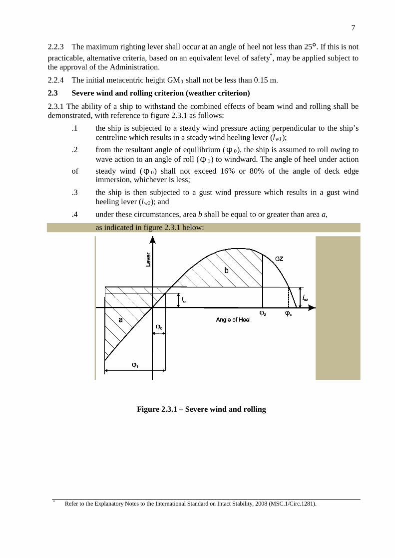
2.3.1 The ability of a ship to withstand the combined effects of beam wind and rolling shall be demonstrated, with reference to figure 2.3.1 as follows:
.1 the ship is subjected to a steady wind pressure acting perpendicular to the ship’s centreline which results in a steady wind heeling lever (lw1);
.2 from the resultant angle of equilibrium (ϕ0), the ship is assumed to roll owing to wave action to an angle of roll (ϕ1) to windward. The angle of heel under action
of steady wind (ϕ0) shall not exceed 16% or 80% of the angle of deck edge immersion, whichever is less;
.3 the ship is then subjected to a gust wind pressure which results in a gust wind heeling lever (lw2); and
.4 under these circumstances, area b shall be equal to or greater than area a,
as indicated in figure 2.3.1 below:
Figure 2.3.1 – Severe wind and rolling
* Refer to the Explanatory Notes to the International Standard on Intact Stability, 2008 (MSC.1/Circ.1281).

8
where the angles in figure 2.3.1 are defined as follows: ϕ0 = angle of heel under action of steady wind
ϕ1 = angle of roll to windward due to wave action (see 2.3.1.2, 2.3.4 and footnote 6)
ϕ2 = angle of down-flooding (ϕ f) or 50° or ϕc, whichever is less,
where:
ϕ f = angle of heel at which openings in the hull, superstructures or deckhouses which cannot be closed weathertight immerse. In applying this criterion, small openings through which progressive flooding cannot take place need not be considered as open
ϕc = angle of second intercept between wind heeling lever lw2 and GZ curves.
2.3.2 The wind heeling levers lw1 and lw2 referred to in 2.3.1.1 and 2.3.1.3 are constant values at all angles of inclination and shall be calculated as follows:
lw1
lw2 1.5 * lw1
where: P = wind pressure of 504 Pa. The value of P used for ships in restricted service
may be reduced subject to the approval of the Administration
A = projected lateral area of the portion of the ship and deck cargo above the waterline (m2)
Z = vertical distance from the centre of A to the centre of the underwater lateral area or approximately to a point at one half the mean draught (m)
∆ = displacement (t) g = gravitational acceleration of 9.81 m/s2.
2.3.3 Alternative means for determining the wind heeling lever (lw1) may be accepted, to the satisfaction of the Administration, as an equivalent to calculation in 2.3.2. When such alternative tests are carried out, reference shall be made based on the Guidelines developed by the Organization*. The wind velocity used in the tests shall be 26 m/s in full scale with uniform velocity profile. The value of wind velocity used for ships in restricted services may be reduced to the satisfaction of the Administration.
* Refer to the Interim Guidelines for alternative assessment of the weather criterion (MSC.1/Circ.1200).

9
k = 1.0 for round-bilged ship having no bilge or bar keels
k
=
0.7 for a ship having sharp bilges
k = as shown in table 2.3.4-3 for a ship having bilge keels, a bar keel or both
2.3.4 The angle of roll* (cp1) referred to in 2.3.1.2 shall be calculated as follows:
ϕ1 = 109 * k * X 1 * X 2 * (degrees)
where:
X1 = factor as shown in table 2.3.4-1
X2 = factor as shown in table 2.3.4-2
k = factor as follows:
r = 0.73 + 0.6 OG/d
with:
OG = KG - d
d = mean moulded draught of the ship (m)
s = factor as shown in table 2.3.4-4, where T is the ship roll natural period. In absence of sufficient information, the following approximate formula can be used:
Rolling period
where:
C = 0.373 + 0.023(B/d) - 0.043(lw1/100).
The symbols in tables 2.3.4-1, 2.3.4-2, 2.3.4-3 and 2.3.4-4 and the formula for the rolling period are defined as follows:
lw1 = length of the ship at waterline (m)
B = moulded breadth of the ship (m)
d = mean moulded draught of the ship (m)
* The angle of roll for ships with anti-rolling devices shall be determined without taking into account the operation of these devices unless the Administration is satisfied with the proof that the devices are effective even with sudden shutdown of their supplied power.

10
CB = block coefficient (-)
Ak = total overall area of bilge keels, or area of the lateral projection of the bar keel, or sum of these areas (m²)
GM = metacentric height corrected for free surface effect (m).
Table 2.3.4-1 - Values of factor X1
B/d X1
≤ 2.4 1.0 2.5 0.98 2.6 0.96 2.7 0.95 2.8 0.93 2.9 0.91 3.0 0.90 3.1 0.88 3.2 0.86 3.4 0.82
≥ 3.5 0.80
Table 2.3.4-2 – Values of factor X2
CB X2
≤ 0.45 0.75 0.50 0.82 0.55 0.89 0.60 0.95 0.65 0.97
≥ 0.70 1.00
Table 2.3.4-3 – Values of factor k
Ak x 100 Lm x B
k
0 1.0 1.0 0.98 1.5 0.95 2.0 0.88 2.5 0.79 3.0 0.74 3.5 0.72
≥ 4.0 0.70
11
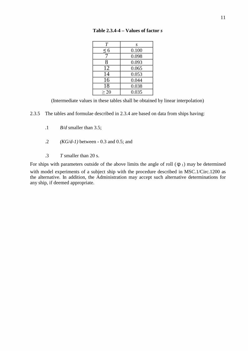
Table 2.3.4-4 – Values of factor s
T s ≤ 6 0.100 7 0.098 8 0.093 12 0.065 14 0.053 16 0.044 18 0.038
≥ 20 0.035
(Intermediate values in these tables shall be obtained by linear interpolation) 2.3.5 The tables and formulae described in 2.3.4 are based on data from ships having:
.1 B/d smaller than 3.5;
.2 (KG/d-1) between - 0.3 and 0.5; and
.3 T smaller than 20 s.
For ships with parameters outside of the above limits the angle of roll (ϕ1) may be determined with model experiments of a subject ship with the procedure described in MSC.1/Circ.1200 as the alternative. In addition, the Administration may accept such alternative determinations for any ship, if deemed appropriate.
12
CHAPTER 3
SPECIAL CRITERIA FOR CERTAIN TYPES OF SHIPS 3.1 Passenger ships
Passenger ships shall comply with the requirements of 2.2 and 2.3. 3.1.1 In addition, the angle of heel on account of crowding of passengers to one side as defined below shall not exceed 10°.
3.1.1.1 A minimum weight of 75 kg shall be assumed for each passenger except that this value may be increased subject to the approval of the Administration. In addition, the mass and distribution of the luggage shall be approved by the Administration.
3.1.1.2 The height of the centre of gravity for passengers shall be assumed equal to:
.1 1 m above deck level for passengers standing upright. Account may be taken, if necessary, of camber and sheer of deck; and
.2 0.3 m above the seat in respect of seated passengers. 3.1.1.3 Passengers and luggage shall be considered to be in the spaces normally at their disposal, when assessing compliance with the criteria given in 2.2.1 to 2.2.4.
3.1.1.4 Passengers without luggage shall be considered as distributed to produce the most unfavourable combination of passenger heeling moment and/or initial metacentric height, which may be obtained in practice, when assessing compliance with the criteria given in 3.1.1 and 3.1.2, respectively. In this connection, a value higher than four persons per square metre is not necessary.
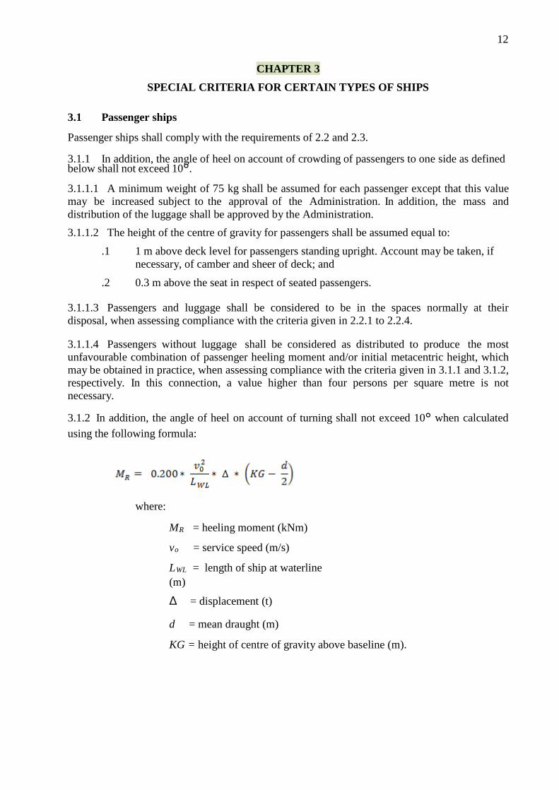
3.1.2 In addition, the angle of heel on account of turning shall not exceed 10° when calculated using the following formula:
where:
MR = heeling moment (kNm)
vo = service speed (m/s)
LWL = length of ship at waterline (m)
∆ = displacement (t)
d = mean draught (m) KG = height of centre of gravity above baseline (m).

13 3.2 Oil tankers of 5,000 dwt and above
Oil tankers, as defined in section 2 (Definitions) of the Introduction, shall comply with regulation 27 of Annex I to MARPOL 73/78.
3.3 Cargo ships carrying timber deck cargoes
Cargo ships carrying timber deck cargoes shall comply with the requirements of 2.2 and 2.3 unless the Administration is satisfied with the application of alternative provision 3.3.2.
3.3.1 Scope
The provisions given hereunder apply to all ships of 24 m in length and over engaged in the carriage of timber deck cargoes. Ships that are provided with, and make use of, their timber load line shall also comply with the requirements of regulations 41 to 45 of the 1966 Load Line Convention.
3.3.2 Alternative stability criteria
For ships loaded with timber deck cargoes and provided that the cargo extends longitudinally between superstructures (where there is no limiting superstructure at the after end, the timber deck cargo shall extend at least to the after end of the aftermost hatchway)* transversely for the full beam of ship, after due allowance for a rounded gunwale, not exceeding 4% of the breadth of the ship and/or securing the supporting uprights and which remains securely fixed at large angles of heel may be:
3.3.2.1 The area under the righting lever curve (GZ curve) shall not be less than 0.08 metre- radians up to ϕ = 40° or the angle of flooding if this angle is less than 40°.
3.3.2.2 The maximum value of the righting lever (GZ) shall be at least 0.25 m.
3.3.2.3 At all times during a voyage, the metacentric height GM0 shall not be less than 0.1 m, taking into account the absorption of water by the deck cargo and/or ice accretion on the exposed surfaces (details regarding ice accretion are given in chapter 4, chapter 9 (Icing considerations)).
3.3.2.4 When determining the ability of the ship to withstand the combined effects of beam wind and rolling according to 2.3, the 16° limiting angle of heel under action of steady wind shall be complied with, but the additional criterion of 80% of the angle of deck edge immersion may be ignored.
3.4 Cargo ships carrying grain in bulk
The intact stability of ships engaged in the carriage of grain shall comply with the requirements of the International Standard for the Safe Carriage of Grain in Bulk adopted by resolution MSC.23(59).**
3.5 High-speed craft
High-speed craft, as defined in section 2 (Definitions) of the Introduction, constructed on or after 1 January 1996 but before 1 July 2002, to which chapter X of the 1974 SOLAS Convention applies, shall comply with stability requirements of the 1994 HSC Standard (resolution MSC.36(63)). Any high-speed craft to which chapter X of the 1974 SOLAS Convention applies, irrespective of its date of construction, which has undergone repairs, alterations or modifications of a major character; and a high-speed craft constructed on or after 1 July 2002, shall comply with stability requirements of the 2000 HSC Standard (resolution MSC.97(73)).
* Refer to regulation 44(2) of the International Convention on Load Lines, 1966 or the Protocol of 1988 relating thereto, as amended, as applicable.
** Refer to part C of chapter VI of the 1974 SOLAS Convention as amended by resolution MSC.23(59).

14 CHAPTER 4
RECOMMENDATIONS FOR CERTAIN TYPES OF SHIPS AND
ADDITIONAL STANDARD
GENERAL 4.1 Purpose
The purpose of this part of the Standard is to:
.1 recommend stability criteria and other measures for ensuring the safe operation of
certain types of ships to minimize the risk to such ships, to the personnel on board and to the environment; and
.2 provide standard for stability information, operational provisions against capsizing, icing considerations, considerations for watertight integrity and the determination of lightship parameters.
4.2 Application
4.2.1 This part of the Standard contains recommended intact stability criteria for certain types of ships and other marine vehicles not included in chapter 2 or intended to supplement those of chapter 2 in particular cases regarding size or operation.
4.2.2 Department of Marine Administration may impose additional requirements regarding the design aspects of ships of novel design or ships not otherwise covered by the Standard.
4.2.3 The criteria stated in this part shall give Standard to Department of Marine Administration if no national requirements are applied.

15
CHAPTER 5
RECOMMENDED DESIGN CRITERIA FOR CERTAIN TYPES OF SHIPS 5.1 Fishing vessels
5.1.1 Scope
The provisions given hereunder apply to decked seagoing fishing vessels as defined in section 2 (Definitions) of the Introduction. The stability criteria given in 5.1.3 and 5.1.4 below shall be complied with for all conditions of loading as specified in 6.4.1.6, unless the Department of Marine Administration is satisfied that operating experience justifies departures therefrom.
5.1.2 General precautions against capsizing
Apart from general precautions referred to in chapter 8, 8.1, 8.2 and 8.3, the following measures shall be considered as preliminary Standard on matters influencing safety as related to stability:
.1 all fishing gear and other heavy material shall be properly stowed and placed as low in the vessel as possible;
.2 particular care shall be taken when pull from fishing gear might have a negative effect on stability, e.g., when nets are hauled by power-block or the trawl catches obstructions on the sea-bed. The pull of the fishing gear shall be from as low a point on the vessel, above the waterline, as possible;
.3 gear for releasing the deck load in fishing vessels which carry the catch on deck, e.g., herring, shall be kept in good working condition;
.4 when the main deck is prepared for carrying deck load by dividing it with pound boards, there shall be slots between them of suitable size to allow easy flow of water to freeing ports, thus preventing trapping of water;
.5 to prevent a shift of the fish load carried in bulk, portable divisions in the holds shall be properly installed;
.6 reliance on automatic steering may be dangerous as this prevents changes to course which may be needed in bad weather;
.7 necessary care shall be taken to maintain adequate freeboard in all loading conditions, and where load line regulations are applicable they shall be strictly adhered to at all times; and
.8 particular care shall be taken when the pull from fishing gear results in dangerous heel angles. This may occur when fishing gear fastens onto an underwater obstacle or when handling fishing gear, particularly on purse seiners, or when one of the trawl wires tears off. The heel angles caused by the fishing gear in these situations may be eliminated by employing devices which can relieve or remove excessive forces applied through the fishing gear. Such devices shall not impose a danger to the vessel through operating in circumstances other than those for which they were intended.
16 5.1.3 Recommended general criteria*
5.1.3.1 The general intact stability criteria given in chapter 2,2.2.1 to 2.2.3 shall apply to fishing vessels having a length of 24 m and over, with the exception of requirements on the initial metacentric height GM (chapter 2, 2.2.4), which, for fishing vessels, shall not be less than 0.35 m for single-deck vessels. In vessels with complete superstructure or vessels of 70 m in length and over the metacentric height may be reduced to the satisfaction of the Department of Marine Administration but in no case shall be less than 0.15 m.
5.1.3.2 The adoption by individual countries of simplified criteria which apply such basic
stability values to their own types and classes of vessels is recognized as a practical and valuable method of economically judging the stability.
5.1.3.3 Where arrangements other than bilge keels are provided to limit the angle of roll, the
Administration shall be satisfied that the stability criteria referred to in 5.1.3.1 are maintained in all operating conditions.
5.1.4 Severe wind and rolling criterion (weather criterion) for fishing vessels
5.1.4.1 The Administration may apply the provisions of chapter 2, 2.3 to fishing vessels of 45
m length and over.
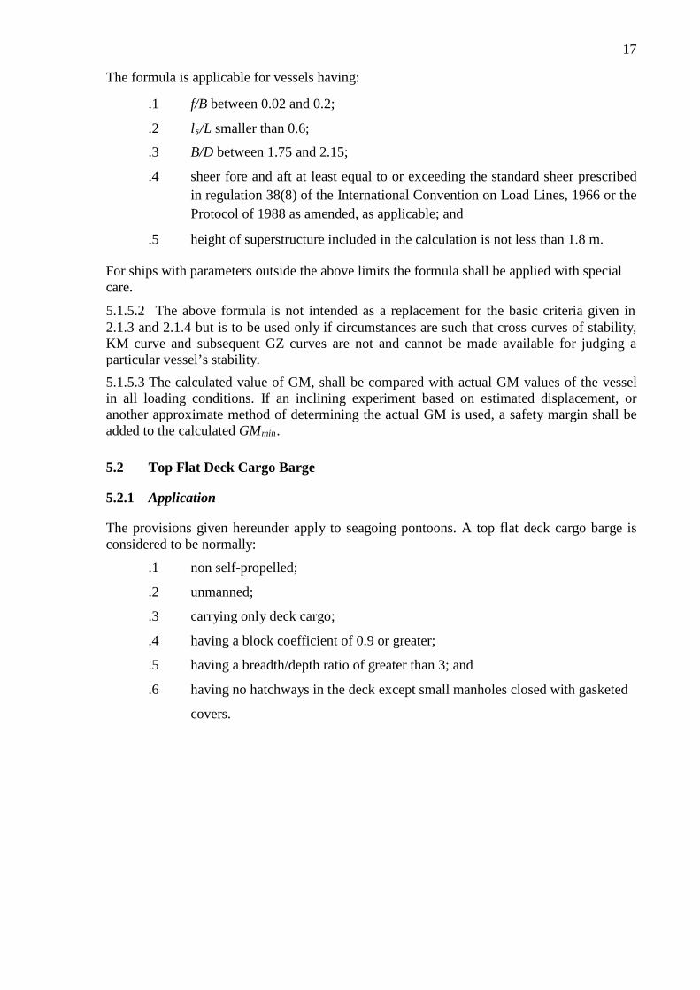
5.1.4.2 For fishing vessels in the length range between 24 m and 45 m, the Administration may apply the provisions of chapter 2, 2.3. Alternatively the values of wind pressure (see chapter 2, 2.3.2) may be taken from the following table:
h (m)
1
2
3
4
5
6 and over P (Pa) 316 386 429 460 485 504
where h is the vertical distance from the centre of the projected vertical area of the vessel above the waterline, to the waterline.
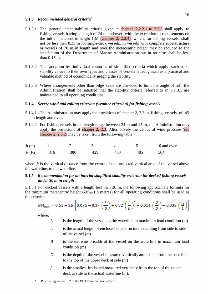
5.1.5 Recommendation for an interim simplified stability criterion for decked fishing vessels under 30 m in length
5.1.5.1 For decked vessels with a length less than 30 m, the following approximate formula for the minimum metacentric height GMmin (in metres) for all operating conditions shall be used as the criterion:
where: L is the length of the vessel on the waterline in maximum load condition (m) ls is the actual length of enclosed superstructure extending from side to side
of the vessel (m)
B is the extreme breadth of the vessel on the waterline in maximum load condition (m)
D is the depth of the vessel measured vertically amidships from the base line to the top of the upper deck at side (m)
f is the smallest freeboard measured vertically from the top of the upper deck at side to the actual waterline (m).
* Refer to regulation III/2 of the 1993 Torremolinos Protocol.
17
The formula is applicable for vessels having:
.1 f/B between 0.02 and 0.2;
.2 ls/L smaller than 0.6;
.3 B/D between 1.75 and 2.15;
.4 sheer fore and aft at least equal to or exceeding the standard sheer prescribed in regulation 38(8) of the International Convention on Load Lines, 1966 or the Protocol of 1988 as amended, as applicable; and
.5 height of superstructure included in the calculation is not less than 1.8 m. For ships with parameters outside the above limits the formula shall be applied with special care.
5.1.5.2 The above formula is not intended as a replacement for the basic criteria given in 2.1.3 and 2.1.4 but is to be used only if circumstances are such that cross curves of stability, KM curve and subsequent GZ curves are not and cannot be made available for judging a particular vessel’s stability.
5.1.5.3 The calculated value of GM, shall be compared with actual GM values of the vessel in all loading conditions. If an inclining experiment based on estimated displacement, or another approximate method of determining the actual GM is used, a safety margin shall be added to the calculated GMmin.
5.2 Top Flat Deck Cargo Barge
5.2.1 Application
The provisions given hereunder apply to seagoing pontoons. A top flat deck cargo barge is considered to be normally:
.1 non self-propelled;
.2 unmanned;
.3 carrying only deck cargo;
.4 having a block coefficient of 0.9 or greater;
.5 having a breadth/depth ratio of greater than 3; and
.6 having no hatchways in the deck except small manholes closed with gasketed
covers.

18 5.2.2 Stability drawings and calculations
The following information is typical of that required to be submitted to the Administration for approval:
.1 lines drawing;
.2 hydrostatic curves;
.3 cross curves of stability;
.4 report of draught and density readings and calculation of lightship displacement and longitudinal centre of gravity;
.5 statement of justification of assumed vertical centre of gravity; and
.6 simplified stability Standard such as a loading diagram, so that the pontoon may be loaded in compliance with the stability criteria.
5.2.3 Concerning the performance of calculations
The following Standard is suggested:
.1 no account shall be taken of the buoyancy of deck cargo (except buoyancy credit for adequately secured timber);
.2 consideration shall be given to such factors as water absorption (e.g., timber), trapped water in cargo (e.g., pipes) and ice accretion;
.3 in performing wind heel calculations:
3.1 the wind pressure shall be constant and for general operations be considered to act on a solid mass extending over the length of the cargo deck and to an assumed height above the deck;
3.2 the centre of gravity of the cargo shall be assumed at a point mid-height of the cargo; and
3.3 the wind lever shall be taken from the centre of the deck cargo to a point at one half the mean draught;
.4 calculations shall be performed covering the full range of operating draughts; and
.5 the down-flooding angle shall be taken as the angle at which an opening through which progressive flooding may take place is immersed. This would not be an opening closed by a watertight manhole cover or a vent fitted with an automatic closure.
5.2.4 Intact stability criteria
5.2.4.1 The area under the righting lever curve up to the angle of maximum righting lever shall not be less than 0.08 metre-radians.
5.2.4.2 The static angle of heel due to a uniformly distributed wind load of 540 Pa (wind speed 30 m/s) shall not exceed an angle corresponding to half the freeboard for the relevant loading condition, where the lever of wind heeling moment is measured from the centroid of the windage area to half the draught.

19 5.2.4.3 The minimum range of stability shall be:
for L ≤ 100 m: 20°; for L 6 150 m: 15°; for intermediate length: by interpolation.
5.3 Containerships greater than 100 m
5.3.1 Application*
These requirements apply to containerships greater than 100 m in length as defined in section 2 (Definitions) of the Introduction. They may also be applied to other cargo ships in this length range with considerable flare or large water plane areas. The Administration may apply the following criteria instead of those in chapter 2, 2.2.
5.3.2 Intact stability
5.3.2.1 The area under the righting lever curve (GZ curve) shall not be less than 0.009/C metre- radians up to ϕ = 30° angle of heel, and not less than 0.016/C metre-radians up to ϕ = 40° or the angle of flooding ϕ f (as defined in chapter 2, 2.2) if this angle is less than 40°.
5.3.2.2 Additionally, the area under the righting lever curve (GZ curve) between the angles of heel of 30° and 40° or between 30° and ϕ f, if this angle is less than 40°, shall not be less than 0.006/C metre-radians.
5.3.2.3 The righting lever GZ shall be at least 0.033/C m at an angle of heel equal or greater than 30°.
5.3.2.4 The maximum righting lever GZ shall be at least 0.042/C m.
5.3.2.5 The total area under the righting lever curve (GZ curve) up to the angle of flooding ϕ f
shall not be less than 0.029/C metre-radians. 5.3.2.6 In the above criteria the form factor C shall be calculated using the formula and figure 5.3-1:
where:
d = mean draught (m)
D' = moulded depth of the ship, corrected for defined parts of volumes within the hatch coamings according to the formula:
D = moulded depth of the ship (m);
BD = moulded breadth of the ship (m);
KG = height of the centre of mass above base, corrected for free surface effect, not be taken as less than d (m);
CB = block coefficient;
CW = water plane coefficient;
lH = length of each hatch coaming within L/4 forward and aft from
* Since the criteria in this section were empirically developed with the data of containerships less than 200 m in length, they shall be applied to ships beyond such limits with special care.

20 amidships (m) (see figure 2.3-1);
b = mean width of hatch coamings within L/4 forward and aft from amidships (m) (see figure 2.3-1);
h = mean height of hatch coamings within L/4 forward and aft from amidships (m) (see figure 2.3-1);
L = length of the ship (m);
B = breadth of the ship on the waterline (m);
Bm = breadth of the ship on the waterline at half mean draught (m).
Figure 5.3-1 The shaded areas in figure 2.3-1 represent partial volumes within the hatch coamings considered contributing to resistance against capsizing at large heeling angles when the ship is on a wave crest.
5.3.2.7 The use of electronic loading and stability instrument is encouraged in determining the ship’s trim and stability during different operational conditions.
5.4 Offshore supply vessels
5.4.1 Application 5.4.1.1 The provisions given hereunder apply to offshore supply vessels, as defined in section 2 (Definitions) of the Introduction, of 24 m in length and over. The alternative stability criteria contained in 2.4.5 apply to vessels of not more than 100 m in length.
5.4.1.2 For a vessel engaged in near-coastal voyages, as defined in section “Definitions”, the principles given in 2.4.2 shall guide the Administration in the development of its national standards. Relaxations from the requirements of the Standard may be permitted by an

21 Administration for vessels engaged in near-coastal voyages off its own coasts provided the operating conditions are, in the opinion of that Administration, such as to render compliance with the provisions of the Standard unreasonable or unnecessary.
5.4.1.3 Where a ship other than an offshore supply vessel, as defined in section “Definitions”, is employed on a similar service, the Administration shall determine the extent to which compliance with the provisions of the Standard is required.
5.4.2 Principles governing near-coastal voyages
5.4.2.1 The Department of Marine Administration defining near-coastal voyages for the purpose of this Standard shall not impose design and construction standards for a vessel entitled to fly the flag of another State and engaged in such voyages in a manner resulting in a more stringent standard for such a vessel than for a vessel entitled to fly its own flag. In no case shall the Administration impose, in respect of a vessel entitled to fly the flag of another State, standards in excess of the Standard for a vessel not engaged in near-coastal voyages.
5.4.2.2 With respect to a vessel regularly engaged in near-coastal voyages off the coast of another State the Administration shall prescribe design and construction standards for such a vessel at least equal to those prescribed by the Government of the State off whose coast the vessel is engaged, provided such standards do not exceed the Standard in respect of a vessel not engaged in near-coastal voyages.
5.4.2.3 A vessel which extends its voyages beyond a near-coastal voyage shall comply with the present Standard.
5.4.3 Constructional precautions against capsizing
5.4.3.1 Access to the machinery space shall, if possible, be arranged within the forecastle. Any access to the machinery space from the exposed cargo deck shall be provided with two weather tight closures. Access to spaces below the exposed cargo deck shall preferably be from a position within or above the superstructure deck.
5.4.3.2 The area of freeing ports in the side bulwarks of the cargo deck shall at least meet the requirements of regulation 24 of the National Regulation on Load Line. The disposition of the freeing ports shall be carefully considered to ensure the most effective drainage of water trapped in pipe deck cargoes or in recesses at the after end of the forecastle. In vessels operating in areas where icing is likely to occur, no shutters shall be fitted in the freeing ports.
5.4.3.3 The area provided for drainage of the pipe stowage positions shall be in excess of the required freeing port area in the cargo deck bulwarks and shall not be fitted with shutters.
5.4.3.4 A vessel engaged in towing operations shall be provided with means for quick release of the towing hawser.
5.4.4 Operational procedures against capsizing
5.4.4.1 The arrangement of cargo stowed on deck shall be such as to avoid any obstruction of the freeing ports or of the areas necessary for the drainage of pipe stowage positions to the freeing ports.
5.4.4.2 A minimum freeboard at the stern of at least 0.005 L shall be maintained in all operating conditions.
5.4.5 Stability criteria
5.4.5.1 The stability criteria given in chapter 2, 2.2 shall apply to all offshore supply vessels

22 except those having characteristics which render compliance with chapter 2, 2.2 impracticable.
5.4.5.2 The following equivalent criteria shall be applied where a vessel’s characteristics render compliance with chapter 2, 2.2 impracticable:
.1 the area under the curve of righting levers (GZ curve) shall not be less than 0.07
metre-radians up to an angle of 15° when the maximum righting lever (GZ) occurs at 15° and 0.055 metre-radians up to an angle of 30° when the maximum righting lever (GZ) occurs at 30° or above. Where the maximum righting lever (GZ) occurs at angles of between 15° and 30°, the corresponding area under the righting lever curve shall be:
0.055 + 0.001 (30° – ϕmax) metre-radians*;
.2 the area under the righting lever curve (GZ curve) between the angles of heel of 30° and 40°, or between 30° and ϕ f if this angle is less than 40°, shall be not less than 0.03 metre-radians;
.3 the righting lever (GZ) shall be at least 0.2 m at an angle of heel equal to or
greater than 30°;
.4 the maximum righting lever (GZ) shall occur at an angle of heel not less than 15°;
.5 the initial transverse metacentric height (GMo) shall not be less than 0.15 m; and
.6 reference is made also to chapter 2, 2.1.3 to 2.1.5 and chapter 8, 8.1. 5.5 Special purpose ships
5.5.1 Application
The provisions given hereunder apply to special purpose ships, as defined in section 2 (Definitions) of the Introduction, of not less than 500 gross tonnage. The Department of Marine Administration may also apply these provisions as far as reasonable and practicable to special purpose ships of less than 500 gross tonnage.
5.5.2 Stability criteria
The intact stability of special purpose ships shall comply with the provisions given in chapter 2, 2.2 except that the alternative criteria given in chapter 5, 5.4.5 which apply to offshore supply vessels may be used for special purpose ships of less than 100 m in length of similar design and characteristics.
5.6 Mobile offshore drilling units (MODUs)
5.6.1 Application
5.6.1.1 The provisions given hereunder apply to mobile offshore drilling units as defined in section 2 (Definitions) of the Introduction, the keels of which are laid or which are at a similar stage of construction on or after 1 May 1991. For MODUs constructed before that date, the corresponding provisions of chapter 6 of resolution A.414(XI) shall apply.
5.6.1.2 The coastal State may permit any unit designed to a lesser standard than that of this chapter to engage in operations, having taken account of the local environmental conditions. Any such unit shall, however, comply with safety requirements which in the opinion of the coastal State are adequate for the intended operation and ensure the overall safety of the unit and the personnel on board.
* ϕmax is the angle of heel in degrees at which the righting lever curve reaches its maximum.

23
5.6.2 Righting moment and wind heeling moment curves
5.6.2.1. Curves of righting moments and of wind heeling moments similar to figure 5.6-1 with supporting calculations shall be prepared covering the full range of operating draughts, including those in transit conditions, taking into account the maximum deck cargo and equipment in the most unfavourable position applicable. The righting moment curves and wind heeling moment curves shall be related to the most critical axes. Account shall be taken of the free surface of liquids in tanks.
First intercept Second intercept
Figure 5.6-1 - Righting moment and wind heeling moment curves 5.6.2.2 Where equipment is of such a nature that it can be lowered and stowed, additional wind heeling moment curves may be required and such data shall clearly indicate the position of such equipment.
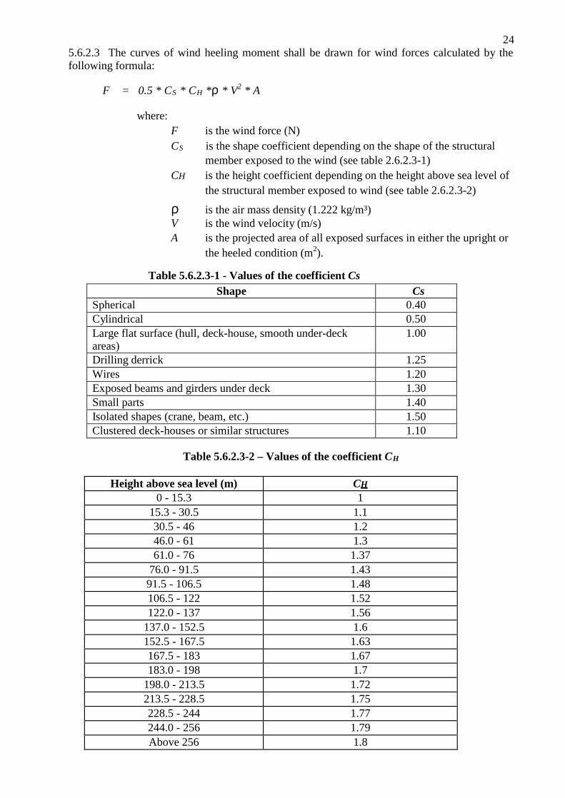
24 5.6.2.3 The curves of wind heeling moment shall be drawn for wind forces calculated by the following formula:
F = 0.5 * CS * CH *ρ * V2 * A
where: F is the wind force (N) CS is the shape coefficient depending on the shape of the structural
member exposed to the wind (see table 2.6.2.3-1) CH is the height coefficient depending on the height above sea level of
the structural member exposed to wind (see table 2.6.2.3-2)
ρ is the air mass density (1.222 kg/m³) V is the wind velocity (m/s) A is the projected area of all exposed surfaces in either the upright or
the heeled condition (m2).
Table 5.6.2.3-1 - Values of the coefficient Cs
Shape Cs Spherical 0.40 Cylindrical 0.50 Large flat surface (hull, deck-house, smooth under-deck areas)
1.00
Drilling derrick 1.25 Wires 1.20 Exposed beams and girders under deck 1.30 Small parts 1.40 Isolated shapes (crane, beam, etc.) 1.50 Clustered deck-houses or similar structures 1.10
Table 5.6.2.3-2 – Values of the coefficient CH
Height above sea level (m) CH
0 - 15.3 1 15.3 - 30.5 1.1 30.5 - 46 1.2 46.0 - 61 1.3 61.0 - 76 1.37
76.0 - 91.5 1.43 91.5 - 106.5 1.48 106.5 - 122 1.52 122.0 - 137 1.56
137.0 - 152.5 1.6 152.5 - 167.5 1.63 167.5 - 183 1.67 183.0 - 198 1.7
198.0 - 213.5 1.72 213.5 - 228.5 1.75 228.5 - 244 1.77 244.0 - 256 1.79 Above 256 1.8

25 5.6.2.4 Wind forces shall be considered from any direction relative to the unit and the value of the wind velocity shall be as follows:
.1 in general, a minimum wind velocity of 36 m/s (70 knots) for offshore service shall be used for normal operating conditions and a minimum wind velocity of 51.5 m/s (100 knots) shall be used for the severe storm conditions; and
.2 where a unit is to be limited in operation to sheltered locations (protected inland waters such as lakes, bays, swamps, rivers, etc.), consideration shall be given to a reduced wind velocity of not less than 25.8 m/s (50 knots) for normal operating conditions.
5.6.2.5 In calculating the projected areas to the vertical plane, the area of surfaces exposed to wind due to heel or trim, such as under decks, etc., shall be included, using the appropriate shape factor. Open truss work may be approximated by taking 30% of the projected block area of both the front and back section, i.e. 60% of the projected area of one side.
5.6.2.6 In calculating the wind heeling moments, the lever of the wind overturning force shall be taken vertically from the centre of pressure of all surfaces exposed to the wind to the centre of lateral resistance of the underwater body of the unit. The unit is to be assumed floating free of mooring restraint.
5.6.2.7 The wind heeling moment curve shall be calculated for a sufficient number of heel angles to define the curve. For ship-shaped hulls the curve may be assumed to vary as the cosine function of ship heel.
5.6.2.8 Wind heeling moments derived from wind-tunnel tests on a representative model of the unit may be considered as alternatives to the method given in 5.6.2.3 to 5.6.2.7. Such heeling moment determination shall include lift and drag effects at various applicable heel angles.
5.6.3 Intact stability criteria
5.6.3.1 The stability of a unit in each mode of operation shall meet the following criteria (see also figure 2.6-2):
.1 for surface and self-elevating units the area under the righting moment curve to the second intercept or down-flooding angle, whichever is less, shall be not less than 40% in excess of the area under the wind heeling moment curve to the same limiting angle;
.2 for column-stabilized units the area under the righting moment curve to the angle of down-flooding shall be not less than 30% in excess of the area under the wind heeling moment curve to the same limiting angle; and
.3 the righting moment curve shall be positive over the entire range of angles from upright to the second intercept.
Figure 5.6-2 – Righting moment and heeling moment curves
26 5.6.3.2 Each unit shall be capable of attaining a severe storm condition in a period of time consistent with the meteorological conditions. The procedures recommended and the approximate length of time required, considering both operating conditions and transit conditions, shall be contained in the operating manual, as referred to in 3.6.2. It shall be possible to achieve the severe storm condition without the removal or relocation of solid consumables or other variable load. However, the Administration may permit loading a unit past the point at which solid consumables would have to be removed or relocated to go to severe storm condition under the following conditions, provided the allowable KG requirement is not exceeded:
.1 in a geographic location where weather conditions annually or seasonally do not become sufficiently severe to require a unit to go to severe storm condition; or
.2 where a unit is required to support extra deckload for a short period of time that is well within the bounds of a favourable weather forecast.
The geographic locations and weather conditions and loading conditions when this is permitted shall be identified in the operating manual.
5.6.3.3 Alternative stability criteria may be considered by the Administration provided an equivalent level of safety is maintained and if they are demonstrated to afford adequate positive initial stability. In determining the acceptability of such criteria, the Administration shall consider at least the following and take into account as appropriate:
.1 environmental conditions representing realistic winds (including gusts) and waves appropriate for world-wide service in various modes of operation;
.2 dynamic response of a unit. Analysis shall include the results of wind-tunnel tests, wave tank model tests, and non-linear simulation, where appropriate. Any wind and wave spectra used shall cover sufficient frequency ranges to ensure that critical motion responses are obtained;
.3 potential for flooding taking into account dynamic responses in a seaway;
.4 susceptibility to capsizing considering the unit’s restoration energy and the static inclination due to the mean wind speed and the maximum dynamic response; and
.5 an adequate safety margin to account for uncertainties. An example of alternative criteria for twin-pontoon column-stabilized semi-submersible units is given in section 2.6.4.
5.6.4 An example of alternative intact stability criteria for twin-pontoon column-stabilized
semi-submersible units
5.6.4.1 The criteria given below apply only to twin-pontoon column-stabilized semi- submersible units in severe storm conditions which fall within the following ranges of parameters:
Vp/Vt is between 0.48 and 0.58
Awp/(Vc)2/3 is between 0.72 and 1.00
Lwp/[Vc * (Lptn/2)] is between 0.40 and 0.70
The parameters used in the above equations are defined in paragraph 2.6.4.3.

27
5.6.4.2 Intact stability criteria The stability of a unit in the survival mode of operation shall meet the following criteria.
5.6.4.2.1 Capsize criteria
These criteria are based on the wind heeling moment and righting moment curves calculated as shown in section 5.6.2 of the Standard at the survival draught. The reserve energy area ‘B’ shall be equal to or greater than 10% of the dynamic response area ‘A’ as shown in figure 5.6-3.
Area ‘B’/Area ‘A’ ≥ 0.10
where:
Area ‘A’ is the area under the righting moment curve measured from ϕ1 to (ϕ1 + 1.15 * ϕdyn)
Area ‘B’ is the area under the righting moment curve measured from
(ϕ1 + 1.15 * ϕdyn) to ϕ2
ϕ1 is the first intercept with the 100 knot wind moment curve
ϕ2 is the second intercept with the 100 knot wind moment curve
ϕdyn is the dynamic response angle due to waves and fluctuating wind
ϕdyn = (10.3 + 17.8 * C)/(1 + GM/(1.46 + 0.28 * BM)) C Parameters used in the above equations are defined in paragraph 5.6.4.3.
Figure 5.6-3 – Righting moment and heeling moment curves
5.6.4.2.2 Down-flooding criteria
These criteria are based on the physical dimensions of the unit and the relative motion of the unit about a static inclination due to a 75 knot wind measured at the survival draught. The initial down-flooding distance (DFD0) shall be greater than the reduction in down-flooding distance at the survival draught as shown in figure 5.6-4.

28
DFD0 - RDFD > 0.0
where:
DFD0 is the initial down-flooding distance to Dm (m)
RDFD is the reduction in down-flooding distance (m) equal to SF (k * QSD1 + RMW)
SF is equal to 1.1, which is a safety factor to account for uncertainties in the analysis, such as non-linear effects
k (correlation factor) is equal to
0.55 + 0.08 * (a - 4) + 0.056 * (1.52 - GM);
(GM cannot be taken to be greater than 2.44 m)
a is equal to (FBD0/Dm)*(Sptn * Lcc)/Awp
(a cannot be taken to be less than 4)
QSD1 is equal to DFD0 minus quasi-static down-flooding distance at #1 (m), but not to be taken less than 3 m
RMW is the relative motion due to waves about #1 (m), equal to 9.3 + 0.11 * (X - 12.19) X is equal to Dm *(Vt/Vp)*(Awp
2/Iwp)*(Lccc/Lptn) (X cannot be taken to be less than 12.19 m).
Figure 5.6-4 – Definition of down-flooding distance and relative motion The parameters used in the above equations are defined in paragraph 5.6.4.3.
5.6.4.3 Geometric parameters
Awp is the waterplane area at the survival draught, including the effects of bracing members as applicable (m2).
Aw is the effective wind area with the unit in the upright position (i.e. the product of projected area, shape coefficient and height coefficient) (m 2).
BM is the vertical distance from the metacentre to the centre of buoyancy with the unit in the upright position (m).
Dm is the initial survival draught (m).
GM
BM
VCPwl
.................................................................................
.................................................................................
.................................................................................
= …....... m = ........... m
= ........... m
Aw
Vt
Vc
Vp
Iwp
.................................................................................
.................................................................................
.................................................................................
.................................................................................
.................................................................................
= ........... m2
= .......... m3
= .......... m3
= .......... m3
= .......... m4
Lptn
.................................................................................
= .......... m
29 FBD0 is the vertical distance from Dm, to the top of the upper exposed weathertight deck
at the side (m). GM for paragraph 5.6.4.2.1, GM is the metacentric height measured about the roll or
diagonal axis, whichever gives the minimum reserve energy ratio, ‘B’/‘A’. This axis is usually the diagonal axis as it possesses a characteristically larger projected wind area which influences the three characteristic angles mentioned above (m).
GM for paragraph 5.6.4.2.2, GM is the metacentric height measured about the axis which gives the minimum down-flooding distance margin (i.e. generally the direction that gives the largest QSD1) (m).
Iwp is the water plane second moment of inertia at the survival draught, including the effects of bracing members as applicable (m 4).
Lccc is the longitudinal distance between centres of the corner columns (m). Lptn is the length of each pontoon (m). Sptn is the transverse distance between the centrelines of the pontoons (m). Vc is the total volume of all columns from the top of the pontoons to the top of the
column structure, except for any volume included in the upper deck (m 3). Vp is the total combined volume of both pontoons (m 3). Vt is the total volume of the structures (pontoons, columns and bracings) contributing
to the buoyancy of the unit, from its baseline to the top of the column structure, except for any volume included in the upper deck (m 3).
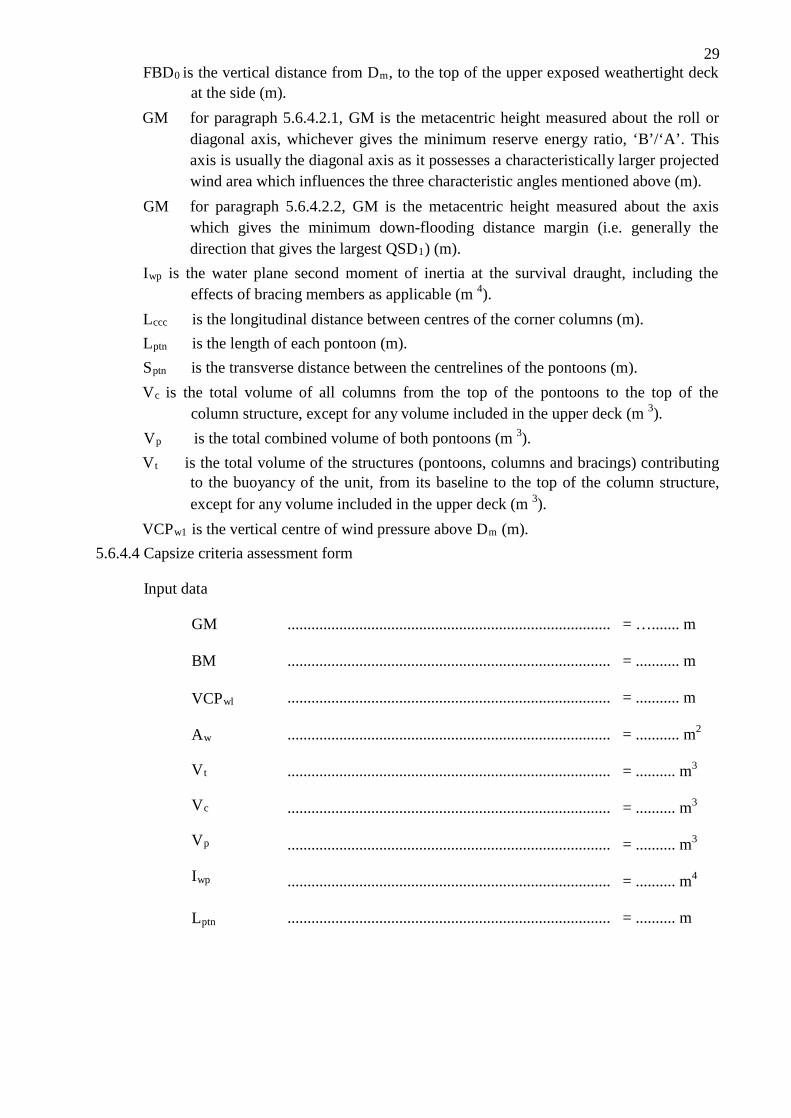
VCPw1 is the vertical centre of wind pressure above Dm (m). 5.6.4.4 Capsize criteria assessment form
Input data

30 Determine
ϕ1 ................................................................................. = .......... deg
ϕ2 ................................................................................. = .......... deg .......... m-1
C = (Lptn5/3 * VCPwl * Aw * Vp * Vc
1/3)/( Iwp5/3 * Vt) ...... =
ϕdyn = (10.3 + 17.8 C)/(1 + GM/(1.46 + 0.28 BM)) …...... = .......... deg
Area 'A' ................................................................................. = ......... m-deg
Area 'B' ................................................................................. = ......... m-deg
Results Reserve energy ratio:
'B'/ 'A' = ………………… (minimum = 0.1)
GM = ………………m (KG = ………. m )
Note: The minimum GM is that which produces a 'B' / 'A' ratio = 0.1 5.6.4.5 Down-flooding criteria assessment form
Input data
DFD0 .............................................................................. = .............. m
FBD0 .............................................................................. = .............. m
GM .............................................................................. = .............. m
Dm .............................................................................. = .............. m
Vt .............................................................................. = .............. m³
Vp .............................................................................. = .............. m³
Awp .............................................................................. = .............. m²
Iwp .............................................................................. = .............. m4
Lccc .............................................................................. = .............. m
Lptn .............................................................................. = .............. m
Sptn .............................................................................. = .............. m
SF .............................................................................. = 1.1
Determine

31
ϕ1 ………………………………………… = .... deg
DFD1 ………………………………………… = .... m
QSD1 = DFD0 - DFD1..............………………… = .... m
a = (FBDo/Dm)*(Sptn * Lccc)/Awp ……………… = .... (amin = 4)
k = 0.55 + 0.08 * (a - 4) + 0.056 * (1.52 - GM)… = .... m (GMmax = 2.44 m)
X = Dm*(Vt/Vp)*(Awp2/Iwp)(Lccc/Lptn)……….… = .... m (Xmin = 12.19
m)
RMW = 9.3 + 0.11 * (X - 12.19)…………………...…… = .... m
RDFD = SF*(k * QSD1 + RMW)…………………...…… = .... m
Results Down-flooding margin:
DFDO - RDFD = ……………………….. (minimum = 0.0 m) GM = ………………m (KG = ………. m )
Note: The minimum GM is that which produces a down-flooding margin = 0.0 m.
32
CHAPTER 6
STANDARD IN PREPARING STABILITY INFORMATION 6.1 Effect of free surfaces of liquids in tanks
6.1.1 For all loading conditions, the initial metacentric height and the righting lever curve shall be corrected for the effect of free surfaces of liquids in tanks.
6.1.2 Free surface effects shall be considered whenever the filling level in a tank is less than 98% of full condition. Free surface effects need not be considered where a tank is nominally full, i.e. filling level is 98% or above. Free surface effects for small tanks may be ignored under condition specified in 6.1.12.*
But nominally full cargo tanks shall be corrected for free surface effects at 98% filling level. In doing so, the correction to initial metacentric height shall be based on the inertia moment of liquid surface at 5° of heeling angle divided by displacement, and the correction to righting lever is suggested to be on the basis of real shifting moment of cargo liquids.
6.1.3 Tanks which are taken into consideration when determining the free surface correction may be in one of two categories:
.1 tanks with filling levels fixed (e.g., liquid cargo, water ballast). The free surface correction shall be defined for the actual filling level to be used in each tank; or
.2 tanks with filling levels variable (e.g., consumable liquids such as fuel oil, diesel oil and fresh water, and also liquid cargo and water ballast during liquid transfer operations). Except as permitted in 6.1.5 and 6.1.6, the free surface correction shall be the maximum value attainable between the filling limits envisaged for each tank, consistent with any operating instructions.
6.1.4 In calculating the free surface effects in tanks containing consumable liquids, it shall be assumed that for each type of liquid at least one transverse pair or a single centreline tank has a free surface and the tank or combination of tanks taken into account shall be those where the effect of free surfaces is the greatest.
6.1.5 Where water ballast tanks, including anti-rolling tanks and anti-heeling tanks, are to be filled or discharged during the course of a voyage, the free surface effects shall be calculated to take account of the most onerous transitory stage relating to such operations.
6.1.6 For ships engaged in liquid transfer operations, the free surface corrections at any stage**
of the liquid transfer operations may be determined in accordance with the filling level in each tank at that stage of the transfer operation.
6.1.7 The corrections to the initial metacentric height and to the righting lever curve shall be addressed separately as follows.
* Refer to the intact stability design criteria, contained in MARPOL regulation I/27, together with the associated Unified Interpretation 45.
** A sufficient number of loading conditions representing the initial, intermediate and final stages of the filling or discharge operation using the free surface correction at the filling level in each tank at the considered stage may be evaluated to fulfil this recommendation.

33
6.1.8 In determining the correction to initial metacentric height, the transverse moments of inertia of the tanks shall be calculated at 0° angle of heel according to the categories indicated in 3.1.3.
6.1.9 The righting lever curve may be corrected by any of the following methods subject to the agreement of the Administration:
.1 correction based on the actual moment of fluid transfer for each angle of heel calculated; or
.2 correction based on the moment of inertia, calculated at 0° angle of heel, modified at each angle of heel calculated.
6.1.10 Corrections may be calculated according to the categories indicated in 6.1.2.
6.1.11 Whichever method is selected for correcting the righting lever curve, only that method shall be presented in the ship’s stability booklet. However, where an alternative method is described for use in manually calculated loading conditions, an explanation of the differences which may be found in the results, as well as an example correction for each alternative, shall be included.
6.1.12 Small tanks which satisfy the following condition corresponding to an angle of inclination of 30°, need not be included in the correction:
Mfs / ∆min < 0.01 m
where:
Mfs free surface moment (mt)
∆min is the minimum ship displacement calculated at dmin (t)
dmin is the minimum mean service draught of the ship without cargo, with 10% stores and minimum water ballast, if required (m).
6.1.13 The usual remainder of liquids in empty tanks need not be taken into account in calculating the corrections, provided that the total of such residual liquids does not constitute a significant free surface effect.
6.2 Permanent ballast
If used, permanent ballast shall be located in accordance with a plan approved by the Administration and in a manner that prevents shifting of position. Permanent ballast shall not be removed from the ship or relocated within the ship without the approval of the Department of Marine Administration. Permanent ballast particulars shall be noted in the ship’s stability booklet.
6.3 Assessment of compliance with stability criteria*
6.3.1 Except as otherwise required by this Standard, for the purpose of assessing in general whether the stability criteria are met, stability curves using the assumptions given in this Standard shall be drawn for the loading conditions intended by the owner in respect of the ship’s operations.
* Care shall be taken in the assessment of compliance with stability criteria, especially conditions in which liquid transfer operations might be expected or anticipated, to insure that the stability criteria is met at all stages of the voyage.

34 6.3.2 If the owner of the ship does not supply sufficiently detailed information regarding such loading conditions, calculations shall be made for the standard loading conditions.
6.4 Standard conditions of loading to be examined
6.4.1 Loading conditions
The standard loading conditions referred to in the text of the present Standard are as follows.
6.4.1.1 For a passenger ship:
.1 ship in the fully loaded departure condition with cargo, full stores and fuel and
with the full number of passengers with their luggage;
.2 ship in the fully loaded arrival condition, with cargo, the full number of passengers and their luggage but with only 10% stores and fuel remaining;
.3 ship without cargo, but with full stores and fuel and the full number of passengers and their luggage; and
.4 ship in the same condition as at 0 above with only 10% stores and fuel remaining. 6.4.1.2 For a cargo ship:
.1 ship in the fully loaded departure condition, with cargo
homogeneously distributed throughout all cargo spaces and with full stores and fuel;
.2 ship in the fully loaded arrival condition with cargo homogeneously distributed throughout all cargo spaces and with 10% stores and fuel remaining;
.3 ship in ballast in the departure condition, without cargo but with full stores and fuel; and
.4 ship in ballast in the arrival condition, without cargo and with 10% stores and fuel remaining.
6.4.1.3 For a cargo ship intended to carry deck cargoes:
.1 ship in the fully loaded departure condition with cargo homogeneously distributed in the holds and with cargo specified in extension and mass on deck, with full stores and fuel; and
.2 ship in the fully loaded arrival condition with cargo homogeneously distributed in holds and with a cargo specified in extension and mass on deck, with 10% stores and fuel.
6.4.1.4 For a ship intended to carry timber deck cargoes: The loading conditions which shall be considered for ships carrying timber deck cargoes are specified in 6.4.1.3. The stowage of timber deck cargoes shall comply with the provisions of chapter 3 of the Standard of Safe Practice for Ships Carrying Timber Deck Cargoes, 1991 (resolution A.715(17)).*
* Refer to chapter VI of the 1974 SOLAS Convention and to part C of chapter VI of the 1974 SOLAS Convention as amended by resolution MSC.22(59).
35
6.4.1.5 For an offshore supply vessel the standard loading conditions shall be as follows:
.1 vessel in fully loaded departure condition with cargo distributed below deck and with cargo specified by position and weight on deck, with full stores and fuel, corresponding to the worst service condition in which all the relevant stability criteria are met;
.2 vessel in fully loaded arrival condition with cargo as specified in 6.4.1.5.1, but with 10% stores and fuel;
.3 vessel in ballast departure condition, without cargo but with full stores and fuel;
.4 vessel in ballast arrival condition, without cargo and with 10% stores and fuel remaining; and
.5 vessel in the worst anticipated operating condition. 6.4.1.6 For fishing vessels the standard loading conditions referred to in 5.1.1 are as follows18:
.1 departure conditions for the fishing grounds with full fuel, stores, ice, fishing gear,
etc.;
.2 departure from the fishing grounds with full catch and a percentage of stores, fuel, etc., as agreed by the Administration;
.3 arrival at home port with 10% stores, fuel, etc. remaining and full catch; and
.4 arrival at home port with 10% stores, fuel, etc. and a minimum catch, which shall normally be 20% of full catch but may be up to 40% provided the Department of Marine Administration is satisfied that operating patterns justify such a value.
6.4.2 Assumptions for calculating loading conditions
6.4.2.1 For the fully loaded conditions mentioned in 6.4.1.2.1, 6.4.1.2.2, 6.4.1.3.1 and 6.4.1.3.2 if a dry cargo ship has tanks for liquid cargo, the effective deadweight in the loading conditions therein described shall be distributed according to two assumptions, i.e. with cargo tanks full, and with cargo tanks empty.
6.4.2.2 In the conditions mentioned in 6.4.1.1.1, 6.4.1.2.1 and 6.4.1.3.1 it shall be assumed that the ship is loaded to its subdivision load line or summer load line or if intended to carry a timber deck cargo, to the summer timber load line with water ballast tanks empty.
6.4.2.3 If in any loading condition water ballast is necessary, additional diagrams shall be calculated taking into account the water ballast. Its quantity and disposition shall be stated.
6.4.2.4 In all cases, the cargo in holds is assumed to be fully homogeneous unless this condition is inconsistent with the practical service of the ship.
17 Refer to chapter VI of the 1974 SOLAS Convention and to part C of chapter VI of the 1974 SOLAS Convention as amended by resolution MSC.22(59).
18 Refer to regulation III/7 of the 1993 Torremolinos Protocol.

36
6.4.2.5 In all cases, when deck cargo is carried, a realistic stowage mass shall be assumed and stated, including the height of the cargo.
6.4.2.6 Considering timber deck cargo the following assumptions are to be made for calculating the loading conditions referred to in 6.4.1.4:
.1 the amount of cargo and ballast shall correspond to the worst service condition
in which all the relevant stability criteria of chapter 2, 2.2 or the optional criteria given in chapter 3, 3.3.2, are met. In the arrival condition, it shall be assumed that the weight of the deck cargo has increased by 10% owing to water absorption.
3.4.2.7 For offshore supply vessels, the assumptions for calculating loading conditions shall be as follows:
.1 if a vessel is fitted with cargo tanks, the fully loaded conditions of 6.4.1.5.1 and 6.4.1.5.2 shall be modified, assuming first the cargo tanks full and then the cargo tanks empty;
.2 if in any loading condition water ballast is necessary, additional diagrams shall be calculated, taking into account the water ballast, the quantity and disposition of which shall be stated in the stability information;
.3 in all cases when deck cargo is carried a realistic stowage weight shall be assumed and stated in the stability information, including the height of the cargo and its centre of gravity;
.4 where pipes are carried on deck, a quantity of trapped water equal to a certain percentage of the net volume of the pipe deck cargo shall be assumed in and around the pipes. The net volume shall be taken as the internal volume of the pipes, plus the volume between the pipes. This percentage shall be 30 if the freeboard amidships is equal to or less than 0.015 L and 10 if the freeboard amidships is equal to or greater than 0.03 L. For intermediate values of the freeboard amidships the percentage may be obtained by linear interpolation. In assessing the quantity of trapped water, the Department of Marine Administration may take into account positive or negative sheer aft, actual trim and area of operation; or
.5 if a vessel operates in zones where ice accretion is likely to occur, allowance for icing shall be made in accordance with the provisions of chapter 6 (Icing considerations).
6.4.2.8 For fishing vessels the assumptions for calculating loading conditions shall be as follows: .1 allowance shall be made for the weight of the wet fishing nets and tackle, etc.,
on deck; .2 allowance for icing, where this is anticipated to occur, shall be made in
accordance with the provisions of 6.3; .3 in all cases the cargo shall be assumed to be homogeneous unless this is
inconsistent with practice;
.4 in conditions referred to in 6.4.1.6.2 and 6.4.1.6.3 deck cargo shall be included if such a practice is anticipated;
.5 water ballast shall normally only be included if carried in tanks which are specially provided for this purpose.
37 6.5 Calculation of stability curves
6.5.1 General
Hydrostatic and stability curves shall be prepared for the trim range of operating loading conditions taking into account the change in trim due to heel (free trim hydrostatic calculation). The calculations shall take into account the volume to the upper surface of the deck sheathing. Furthermore, appendages and sea chests need to be considered when calculating hydrostatics and cross curves of stability. In the presence of port-starboard asymmetry, the most unfavourable righting lever curve shall be used.
6.5.2 Superstructures, deckhouses, etc., which may be taken into account
6.5.2.1 Enclosed superstructures complying with regulation 3(10)(b) of the 1966 Load Line Convention and the Protocol of 1988 relating thereto, as amended, may be taken into account.
6.5.2.2 Additional tiers of similarly enclosed superstructures may also be taken into account. As Standard windows (pane and frame) that are considered without deadlights in additional tiers above the second tier if considered buoyant shall be designed with strength to sustain a safety margin19 with regard to the required strength of the surrounding structure.20
6.5.2.3 Deckhouses on the freeboard deck may be taken into account, provided that they comply with the conditions for enclosed superstructures laid down in regulation 3(10)(b) of the 1966 Load Line Convention and the Protocol of 1988 relating thereto, as amended.
6.5.2.4 Where deckhouses comply with the above conditions, except that no additional exit is provided to a deck above, such deckhouses shall not be taken into account; however, any deck openings inside such deckhouses shall be considered as closed even where no means of closure are provided.
6.5.2.5 Deckhouses, the doors of which do not comply with the requirements of regulation 12 of the 1966 Load Line Convention and the Protocol of 1988 relating thereto, as amended, shall not be taken into account; however, any deck openings inside the deckhouse are regarded as closed where their means of closure comply with the requirements of regulations 15, 17 or 18 of the 1966 Load Line Convention and the Protocol of 1988 relating thereto, as amended.
6.5.2.6 Deckhouses on decks above the freeboard deck shall not be taken into account, but openings within them may be regarded as closed.
6.5.2.7 Superstructures and deckhouses not regarded as enclosed can, however, be taken into account in stability calculations up to the angle at which their openings are flooded (at this angle, the static stability curve shall show one or more steps, and in subsequent computations the flooded space shall be considered non-existent).
6.5.2.5 In cases where the ship would sink due to flooding through any openings, the stability curve shall be cut short at the corresponding angle of flooding and the ship shall be considered to have entirely lost its stability.
6.5.2.6 Small openings such as those for passing wires or chains, tackle and anchors, and also holes of scuppers, discharge and sanitary pipes shall not be considered as open if they submerge at an angle of inclination more than 30%. If they submerge at an angle of 30% or less, these openings shall be assumed open if the Department of Marine Administration considers this to be a source of significant flooding.
6.5.2.7 Trunks may be taken into account. Hatchways may also be taken into account having regard to the effectiveness of their closures.
19 As a Standard for Administrations a safety margin of 30% shall be applied. 20 IMO Standard for testing these windows is to be developed.

38 6.5.3 Calculation of stability curves for ships carrying timber deck cargoes
In addition to the provisions given above, the Administration may allow account to be taken of the buoyancy of the deck cargo assuming that such cargo has a permeability of 25% of the volume occupied by the cargo. Additional curves of stability may be required if the Administration considers it necessary to investigate the influence of different permeabilities and/or assumed effective height of the deck cargo.
6.6 Stability booklet
6.6.1 Stability data and associated plans shall be set up in English. Reference is also made to the International Safety Management (ISM) Code, adopted by the Organization by resolution A.741(18). All translations of the stability booklet shall be approved.
6.6.2 Each ship shall be provided with a stability booklet, approved by the Department of Marine Administration, which contains sufficient information to enable the master to operate the ship in compliance with the applicable requirements contained in the Standard. The Administration may have additional requirements. On a mobile offshore drilling unit, the stability booklet may be referred to as an operating manual. The stability booklet may include information on longitudinal strength. This Standard addresses only the stability-related contents of the booklet.21
6.6.3 For ships carrying timber deck cargoes:
.1 comprehensive stability information shall be supplied which takes into account timber deck cargo. Such information shall enable the master, rapidly and simply,
to obtain accurate Standard as to the stability of the ship under varying conditions of service. Comprehensive rolling period tables or diagrams have proved to be very useful aids in verifying the actual stability conditions;22
.2 the Department of Marine Administration may deem it necessary that the master be given information setting out the changes in deck cargo from that shown in the loading conditions, when the permeability of the deck cargo is significantly different from 25% (refer to 6.5.3); and
.3 conditions shall be shown indicating the maximum permissible amount of deck cargo having regard to the lightest stowage rate likely to be met in service.
21 Refer to regulation II-1/22 of the 1974 SOLAS Convention, as amended, regulation 10 of the International Convention on Load Lines, 1966 or the Protocol of 1988 as amended, as applicable and regulation III/10 of the 1993 Torremolinos Protocol.
39
6.6.4 The format of the stability booklet and the information included will vary dependent on the ship type and operation. In developing the stability booklet, consideration shall be given to including the following information23:
.1 a general description of the ship;
.2 instructions on the use of the booklet;
.3 general arrangement plans showing watertight compartments, closures, vents, downflooding angles, permanent ballast, allowable deck loadings and freeboard diagrams;
.4 hydrostatic curves or tables and cross curves of stability calculated on a free-trimming basis, for the ranges of displacement and trim anticipated in normal operating conditions;
.5 capacity plan or tables showing capacities and centres of gravity for each cargo stowage space;
.6 tank sounding tables showing capacities, centres of gravity, and free surface data for each tank;
.7 information on loading restrictions, such as maximum KG or minimum GM curve or table that can be used to determine compliance with the applicable stability criteria;
.8 standard operating conditions and examples for developing other acceptable loading conditions using the information contained in the stability booklet;
.9 a brief description of the stability calculations done including assumptions;
.10 general precautions for preventing unintentional flooding;
.11 information concerning the use of any special cross-flooding fittings with descriptions of damage conditions which may require cross-flooding;
.12 any other necessary Standard for the safe operation of the ship under normal and emergency conditions;
.13 a table of contents and index for each booklet;
.14 inclining test report for the ship, or:
14.1 where the stability data is based on a sister ship, the inclining test report of that sister ship along with the lightship measurement report for the ship in question; or
14.2 where lightship particulars are determined by other methods than from inclining of the ship or its sister, a summary of the method used to determine those particulars;
.15 recommendation for determination of ship’s stability by means of an in-service inclining test.
22 Refer to regulation II-1/22 of the 1974 SOLAS Convention, as amended, and regulation 10(2) of the International Convention on Load Lines, 1966 or the Protocol of 1988 relating thereto, as amended, as applicable.

40 23 Refer to the Model Loading and Stability Manual (MSC/Circ.920).

41
6.6.5 As an alternative to the stability booklet mentioned in 6.6.1, a simplified booklet in an approved form containing sufficient information to enable the master to operate the ship in compliance with the applicable provisions of the Standard as may be provided at the discretion of the Administration concerned.
6.7 Operational measures for ships carrying timber deck cargoes
6.7.1 The stability of the ship at all times, including during the process of loading and unloading timber deck cargo, shall be positive and to a standard acceptable to the Administration. It shall be calculated having regard to:
.1 the increased weight of the timber deck cargo due to:
1.1 absorption of water in dried or seasoned timber, and
1.2 ice accretion, if applicable (chapter 9 (Icing considerations));
.2 variations in consumables;
.3 the free surface effect of liquid in tanks; and
.4 weight of water trapped in broken spaces within the timber deck cargo and especially logs.
6.7.2 The master shall:
.1 cease all loading operations if a list develops for which there is no satisfactory explanation and it would be imprudent to continue loading;
.2 before proceeding to sea, ensure that:
2.1 the ship is upright;
2.2 the ship has an adequate metacentric height; and
2.3 the ship meets the required stability criteria. 6.7.3 The masters of ships having a length less than 100 m shall also:
.1 exercise good judgement to ensure that a ship which carries stowed logs on deck has sufficient additional buoyancy so as to avoid overloading and loss of stability at sea;
.2 be aware that the calculated GM0 in the departure condition may decrease continuously owing to water absorption by the deck cargo of logs, consumption of fuel, water and stores and ensure that the ship has adequate GM0 throughout the voyage; and
.3 be aware that ballasting after departure may cause the ship’s operating draught to exceed the timber load line. Ballasting and deballasting shall be carried out in accordance with the Standard provided in the Standard of Safe Practice for Ships Carrying Timber Deck Cargoes, 1991 (resolution A.715(17)).
6.7.4 Ships carrying timber deck cargoes shall operate, as far as possible, with a safe margin of stability and with a metacentric height which is consistent with safety requirements but such metacentric height shall not be allowed to fall below the recommended minimum, as specified in chapter 6, 3.3.2.
6.7.5 However, excessive initial stability shall be avoided as it will result in rapid and violent motion in heavy seas which will impose large sliding and racking forces on the cargo causing high stresses on the lashings. Operational experience indicates that metacentric height shall preferably not exceed 3% of the breadth in order to prevent excessive accelerations in rolling provided that the relevant stability criteria given in chapter 3, 3.3.2 are satisfied. This recommendation may not apply to all ships and the master shall take into consideration the

42 stability information obtained from the ship’s stability booklet.
6.8 Operating booklets for certain ships
6.8.1 Special purpose ships and novel craft, shall be provided with additional information in the stability booklet such as design limitations, maximum speed, worst intended weather conditions or other information regarding the handling of the craft that the master needs to operate the ship safely.
6.8.2 For double hull oil tankers of single cargo tank across design, an operation manual for loading and unloading cargo oil shall be provided, including operational procedures of loading and unloading cargo oil and detailed data of the initial metacentric height of the oil tanker and that of free surface correction of liquids in cargo oil tanks and ballast tanks during loading and unloading cargo oil (including ballasting and discharging) and cargo oil washing of tanks.24
6.8.3 The stability booklet of ro-ro passenger ships shall contain information concerning the importance of securing and maintaining all closures watertight due to the rapid loss of stability which may result when water enters the vehicle deck and the fact that capsize can rapidly follow.
24 Refer to the Standard on intact stability of existing tankers during liquid transfer operations (MSC/Circ.706-MEPC/Circ.304).
43 CHAPTER 7
STABILITY CALCULATIONS PERFORMED BY STABILITY INSTRUMENTS
7.1 Stability instruments25
A stability instrument installed onboard shall cover all stability requirements applicable to the ship. The software is subject to approval by the Administration or RO. Active and passive systems are defined in 4.1.2. These requirements cover passive systems and the off-line operation mode of active systems only.
7.1.1 General
7.1.1.1 The scope of stability calculation software shall be in accordance with the approved stability booklet and shall at least include all information and perform all calculations or checks as necessary to ensure compliance with the applicable stability requirements.
7.1.1.2 An approved stability instrument is not a substitute for the approved stability booklet, and is used as a supplement to the approved stability booklet to facilitate stability calculations.
7.1.1.3 The input/output information shall be easily comparable with the approved stability booklet so as to avoid confusion and possible misinterpretation by the operator.
7.1.1.4 An operation manual shall be provided for the stability instrument.
7.1.1.5 The language in which the stability calculation results are displayed and printed out as well as the operation manual is written shall be the same as used in the ship’s approved stability booklet. A translation into a language considered appropriate may be required.
7.1.1.6 The stability instrument is ship specific equipment and the results of the calculations are only applicable to the ship for which it has been approved.
7.1.1.7 In case of modifications of the ship which cause alterations in the stability booklet, the specific approval of any original stability calculation software is no longer valid. The software shall be modified accordingly and re-approved.
7.1.1.8 Any change in software version related to the stability calculation shall be reported to and be approved by the Administration.
7.1.2 Data entry system
7.1.2.1 A passive system requires manual data entry.
7.1.2.2 An active system replaces partly the manual entry with sensors reading and entering the contents of tanks, etc.
7.1.2.3 Any integrated system which controls or initiates actions based on the sensor-supplied inputs is not within the scope of this Standard except the part calculating the stability.
25 Refer to the Guidelines for the approval of stability instruments (MSC.1/Circ.1229).

44
7.1.3 Types of stability software
Three types of calculations performed by stability software are acceptable depending upon a vessel’s stability requirements:
Type 1
Software calculating intact stability only (for vessels not required to meet a damage stability criterion).
Type 2
Software calculating intact stability and checking damage stability on basis of a limit curve (e.g., for vessels applicable to SOLAS part B-1 damage stability calculations, etc.) or previously approved loading conditions.
Type 3
Software calculating intact stability and damage stability by direct application of pre- programmed damage cases for each loading condition (for some tankers, etc.). The results of the direct calculations performed by the stability instrument could be accepted by the Department of Marine Administration even if they differ from the required minimum GM or maximum VCG stated in the approved stability booklet.
Such deviations could be accepted under the condition that all relevant stability requirements will be complied with by the results of the direct calculations.
7.1.4 Functional requirements
7.1.4.1 The stability instrument shall present relevant parameters of each loading condition in order to assist the master in his judgement on whether the ship is loaded within the approved limits. The following parameters shall be presented for a given loading condition:
7.1.4.2 If direct damage stability calculations are performed, the relevant damage cases according to the applicable rules shall be pre-defined for automatic check of a given loading
condition.
7.1.4.3 A clear warning shall be given on screen and in hard copy printout if any of the limitations are not complied with.
7.1.4.4 The data shall be presented on screen and in hard copy printout in a clear unambiguous manner.
7.1.4.5 The date and time of a saved calculation shall be part of the screen display and hard copy printout.
7.1.4.6 Each hard copy printout shall contain identification of the calculation program including version number.
7.1.4.7 Units of measurement shall be clearly identified and used consistently within a loading calculation.
7.1.5 Acceptable tolerances
Depending on the type and scope of programs, the acceptable tolerances shall be determined differently, according to 7.1.5.1 or 7.1.5.2. Deviation from these tolerances shall not be accepted unless the Administration considers that there is a satisfactory explanation for the difference and that there will be no adverse effect on the safety of the ship.
The accuracy of the results shall be determined using an independent program or the approved stability booklet with identical input.

45 7.1.5.1 Programs which use only pre-programmed data from the approved stability booklet as the basis for stability calculations shall have zero tolerances for the printouts of input data.
Output data tolerances shall be close to zero, however, small differences associated with calculation rounding or abridged input data are acceptable. Additionally differences associated with the use of hydrostatic and stability data for trims and the method calculating free surface moments that differ from those in the approved stability booklet are acceptable subject to review by the Department of Marine Administration.
7.1.5.2 Programs which use hull form models as their basis for stability calculations shall have tolerances for the printouts of basic calculated data established against either data from the approved stability booklet or data obtained using the Administration’s approval model.
7.1.6 Approval procedure
7.1.6.1 Conditions of approval of the stability instrument
The software approval includes:
.1 verification of type approval, if any;
.2 verification that the data used is consistent with the current condition of the ship (refer to 7.1.6.2);
.3 verification and approval of the test conditions; and
.4 verification that the software is appropriate for the type of ship and stability calculations required.
The satisfactory operation of the stability instrument is to be verified by testing upon installation (refer to 7.1.8). A copy of the approved test conditions and the operation manual for the stability instrument are to be available on board.
7.1.6.2 Specific approval
7.1.6.2.1 The accuracy of the computational results and actual ship data used by the calculation program for the particular ship on which the program will be installed shall be to the satisfaction of the Department of Marine Administration.
7.1.6.2.2 Upon application for data verification, minimum of four loading conditions shall be taken from the ship’s approved stability booklet, which shall be used as the test conditions. For ships carrying liquids in bulk, at least one of the conditions shall include partially filled tanks. For ships carrying grain in bulk, one of the grain loading conditions shall include a partially filled grain compartment. Within the test conditions each compartment shall be loaded at least once. The test conditions normally shall cover the range of load draughts from the deepest envisaged loaded condition to the light ballast condition and shall include at least one departure and one arrival condition.
7.1.6.2.3 The following data, submitted by the applicant, shall be consistent with arrangements and most recently approved lightship characteristics of the ship according to current plans and documentation on file, subject to possible further verification on board:
.1 identification of the calculation program including version number. Main dimensions, hydrostatic particulars and, if applicable, the ship’s profile;
.2 the position of the forward and aft perpendiculars, and if appropriate, the calculation method to derive the forward and aft draughts at the actual position of the ship’s draught marks;
.3 ship’s lightweight and centre of gravity derived from the most recently approved inclining experiment or light weight survey;
46
.1 installation;
.2 function keys;
.3 menu displays
.4 input and outp
.5 required mini
.6 use of the test
.7 computer-guid
.8 list of warnin
.4 lines plan, offset tables or other suitable presentation of hull form data including all relevant appendages, if necessary to model the ship;
.5 compartment definitions, including frame spacing, and centres of volume, together with capacity tables (sounding/ ullage tables), free surface corrections, if appropriate; and
.6 cargo and consumables distribution for each loading condition.
Verification by the Administration does not absolve the shipowner of responsibility for ensuring that the information programmed into the stability instrument is consistent with the current condition of the ship and approved stability booklet.
7.1.7 User manual
A simple and straightforward user manual written in the same language as the stability booklet shall be provided, containing descriptions and instructions, as appropriate, for at least the following:
; ut data;
mum hardware to operate the software; loading conditions; ed dialogue steps; and
gs.
A user manual in electronic format may be provided in addition to the written manual.
7.1.8 Installation testing
7.1.8.1 To ensure correct working of the stability instrument after the final or updated software has been installed, it is the responsibility of the ship’s master to have test calculations carried out according to the following pattern in the presence of the Department of Marine Administration surveyor or RO. From the approved test conditions at least one load case (other than light ship) shall be calculated.
Note: Actual loading condition results are not suitable for checking the correct working of the stability instrument.
7.1.8.2 Normally, the test conditions are permanently stored in the stability instrument. Steps to be performed:
.1 retrieve the test load case and start a calculation run; compare the stability results with those in the documentation;
.2 change several items of deadweight (tank weights and the cargo weight) sufficiently to change the draught or displacement by at least 10%. The results shall be reviewed to ensure that they differ in a logical way from those of the approved test condition;
.3 revise the above modified load condition to restore the initial test condition and compare the results. The relevant input and output data of the approved test condition shall be replicated; and
.4 alternatively, one or more test conditions shall be selected and the test calculations performed by entering all deadweight data for each selected test condition into the program as if it were a proposed loading. The results shall be verified as identical to the results in the approved copy of the test conditions.
47 7.1.9 Periodical testing
7.1.9.1 It is the responsibility of the ship’s master to check the accuracy of the stability instrument at each annual survey by applying at least one approved test condition. If Department of Marine Administration representative or RO is not present for the stability instrument check, a copy of the test condition results obtained by this check shall be retained on board as documentation of satisfactory testing for the Department of Marine Administration representative’s verification or RO.
7.1.9.2 At each renewal survey this checking for all approved test loading conditions shall be done in the presence of the Department of Marine Administration representative or RO.
7.1.9.3 The testing procedure shall be carried out in accordance with paragraph 4.1.8.
7.1.10 Other requirements
7.1.10.1 Protection against unintentional or unauthorized modification of programs and data shall be provided.
7.1.10.2 The program shall monitor operation and activate an alarm when the program is incorrectly or abnormally used.
7.1.10.3 The program and any data stored in the system shall be protected from corruption by loss of power.
7.1.10.4 Error messages with regard to limitations such as filling a compartment beyond capacity or more than once, or exceeding the assigned load line, etc., shall be included.
7.1.10.5 If any software related to stability measures such as sea keeping abilities of the vessel, evaluation of in-service inclining experiments and processing the results for further calculation, as well as the evaluation of roll period measurements is installed on board, such software shall be reported to the Department of Marine Administration and RO for consideration.
7.1.10.6 Program functionalities shall include mass and moment calculations with numerical and graphical presentation of the results, such as initial stability values, righting lever curve, areas under the righting lever curve and range of stability.
7.1.10.7 All input data from automatically measuring sensors, such as gauging devices or draught reading systems shall be presented to the user for verification. The user shall have the possibility to override faulty readings manually.
48 CHAPTER 8
OPERATIONAL PROVISIONS AGAINST CAPSIZING
8.1 General precautions against capsizing
8.1.1 Compliance with the stability criteria does not ensure immunity against capsizing, regardless of the circumstances, or absolve the master from his responsibilities. Masters shall therefore exercise prudence and good seamanship having regard to the season of the year, weather forecasts and the navigational zone and shall take the appropriate action as to speed and course warranted by the prevailing circumstances.26
8.1.2 Care shall be taken that the cargo allocated to the ship is capable of being stowed so that compliance with the criteria can be achieved. If necessary, the amount shall be limited to the extent that ballast weight may be required.
8.1.3 Before a voyage commences, care shall be taken to ensure that the cargo, cargo handling cranes and sizeable pieces of equipment have been properly stowed or lashed so as to minimize the possibility of both longitudinal and lateral shifting, while at sea, under the effect of acceleration caused by rolling and pitching.27
8.1.4 A ship, when engaged in towing operations, shall possess an adequate reserve of stability to withstand the anticipated heeling moment arising from the tow line without endangering the towing ship. Deck cargo on board the towing ship shall be so positioned as not to endanger the safe working of the crew on deck or impede the proper functioning of the towing equipment and be properly secured. Tow line arrangements shall include towing springs and a method of quick release of the tow.
8.1.5 The number of partially filled or slack tanks shall be kept to a minimum because of their adverse effect on stability. The negative effect on stability of filled pool tanks shall be taken into consideration.
8.1.6 The stability criteria contained in chapter 2 set minimum values, but no maximum values are recommended. It is advisable to avoid excessive values of metacentric height, since these might lead to acceleration forces which could be prejudicial to the ship, its complement, its equipment and to safe carriage of the cargo. Slack tanks may, in exceptional cases, be used as a means of reducing excessive values of metacentric height. In such cases, due consideration shall be given to sloshing effects.
8.1.7 Regard shall be paid to the possible adverse effects on stability where certain bulk cargoes are carried. In this connection, attention shall be paid to the IMO Standard of Safe Practice for Solid Bulk Cargoes.
8.2 Operational precautions in heavy weather
8.2.1 All doorways and other openings, through which water can enter into the hull or deckhouses, forecastle, etc., shall be suitably closed in adverse weather conditions and accordingly all appliances for this purpose shall be maintained on board and in good condition.
26 Refer to the Revised Standard to the master for avoiding dangerous situations in adverse weather and sea conditions (MSC.1/Circ.1228).
27 Refer to the Guidelines for the preparation of the Cargo Securing Manual (MSC/Circ.745).

49
8.2.2 Weathertight and watertight hatches, doors, etc., shall be kept closed during navigation, except when necessarily opened for the working of the ship and shall always be ready for immediate closure and be clearly marked to indicate that these fittings are to be kept closed except for access. Hatch covers and flush deck scuttles in fishing vessels shall be kept properly secured when not in use during fishing operations. All portable deadlights shall be maintained in good condition and securely closed in bad weather.
8.2.3 Any closing devices provided for vent pipes to fuel tanks shall be secured in bad weather.
8.2.4 Fish shall never be carried in bulk without first being sure that the portable divisions in the holds are properly installed.
8.3 Ship handling in heavy weather
8.3.1 In all conditions of loading necessary care shall be taken to maintain a seaworthy freeboard.
8.3.2 In severe weather, the speed of the ship should be reduced if propeller emergence, shipping of water on deck or heavy slamming occurs.
8.3.3 Special attention shall be paid when a ship is sailing in following, quartering or head seas because dangerous phenomena such as parametric resonance, broaching to, reduction of stability on the wave crest, and excessive rolling may occur singularly, in sequence or simultaneously in a multiple combination, creating a threat of capsize. A ship’s speed and/or course shall be altered appropriately to avoid the above-mentioned phenomena.28
8.3.4 Reliance on automatic steering may be dangerous as this prevents ready changes to course which may be needed in bad weather.
8.3.5 Water trapping in deck wells shall be avoided. If freeing ports are not sufficient for the drainage of the well, the speed of the ship shall be reduced or the course changed, or both. Freeing ports provided with closing appliances shall always be capable of functioning and are not to be locked.
8.3.6 Masters shall be aware that steep or breaking waves may occur in certain areas, or in certain wind and current combinations (river estuaries, shallow water areas, funnel shaped bays, etc.). These waves are particularly dangerous, especially for small ships.
8.3.7 In severe weather, the lateral wind pressure may cause a considerable angle of heel. If anti-heeling measures (e.g., ballasting, use of anti-heeling devices, etc.) are used to compensate for heeling due to wind, changes of the ship’s course relative to the wind direction may lead to dangerous angles of heel or capsizing. Therefore, heeling caused by the wind shall not be compensated with anti-heeling measures, unless, subject to the approval by the Department of Marine Administration, the vessel has been proven by calculation to have sufficient stability in worst case conditions (i.e. improper or incorrect use, mechanism failure, unintended course change, etc.). Standard on the use of anti-heeling measures shall be provided in the stability booklet.
28 Refer to the Revised Standard to the master for avoiding dangerous situations in adverse weather and sea conditions (MSC.1/Circ.1228).

50
8.3.8 Use of operational guidelines for avoiding dangerous situations in severe weather conditions or an on-board computer based system is recommended. The method shall be simple to use.
8.3.9 High-speed craft shall not be intentionally operated outside the worst intended conditions and limitations specified in the relevant certificates, or in documents referred to therein.

51
CHAPTER 9
ICING CONSIDERATIONS
9.1 General 9.1.1 For any ship operating in areas where ice accretion is likely to occur, adversely affecting a ship’s stability, icing allowances shall be included in the analysis of conditions of loading.
9.1.2 Administrations are advised to take icing into account and are permitted to apply national standards where environmental conditions are considered to warrant a higher standard than those recommended in the following sections.
9.2 Cargo ships carrying timber deck cargoes
9.2.1 The master shall establish or verify the stability of his ship for the worst service condition, having regard to the increased weight of deck cargo due to water absorption and/or ice accretion and to variations in consumables.29
9.2.2 When timber deck cargoes are carried and it is anticipated that some formation of ice will take place, an allowance shall be made in the arrival condition for the additional weight.
9.3 Fishing vessels
The calculations of loading conditions for fishing vessels (refer to 6.4.2.8) shall, where appropriate, include allowance for ice accretion, in accordance with the following provisions.
9.3.1 Allowance for ice accretion30
For vessels operating in areas where ice accretion is likely to occur, the following icing allowance shall be made in the stability calculations:
.1 30 kg per square metre on exposed weather decks and gangways;
.2 7.5 kg per square metre for projected lateral area of each side of the vessel above
the water plane;
.3 the projected lateral area of discontinuous surfaces of rail, sundry booms, spars (except masts) and rigging of vessels having no sails and the projected lateral area of other small objects shall be computed by increasing the total projected area of continuous surfaces by 5% and the static moments of this area by 10%.
Vessels intended for operation in areas where ice is known to occur shall be:
.4 designed to minimize the accretion of ice; and
.5 equipped with such means for removing ice as the Administration may require;
for example, electrical and pneumatic devices, and/or special tools such as axes or wooden clubs for removing ice from bulwarks, rails and erections.
29 Refer to regulation 44(10) of the 1966 Load Line Convention and regulation 44(7) of the 1988 Load Line Protocol as amended.
30 Refer to regulation III/8 of the 1993 Torremolinos Protocol.
52
9.3.2 Standard relating to ice accretion In the application of the above standards, the following icing areas shall apply:
.1 the area north of latitude 65° 30´ N, between longitude 28° W and the west coast of
Iceland; north of the north coast of Iceland; north of the rhumb line running from latitude 66° N, longitude 15° W to latitude 73° 30´ N, longitude 15° E, north of latitude 73° 30´ N between longitude 15° E and 35° E, and east of longitude 35° E, as well as north of latitude 56° N in the Baltic Sea;
.2 the area north of latitude 43° N bounded in the west by the North American coast
and the east by the rhumb line running from latitude 43° N, longitude 48° W to latitude 63° N, longitude 28° W and thence along longitude 28° W;
.3 all sea areas north of the North American Continent, west of the areas defined in
9.3.2.1 and 9.3.2.2;
.4 the Bering and Okhotsk Seas and the Tartary Strait during the icing season; and
.5 south of latitude 60° S.
A chart to illustrate the areas is attached at the end of this chapter.
For vessels operating in areas where ice accretion may be expected:
.6 within the areas defined in 9.3.2.1, 9.3.2.3, 9.3.2.4 and 9.3.2.5 known to having
icing conditions significantly different from those described in 6.3.1, ice accretion requirements of one half to twice the required allowance may be applied; and
.7 within the area defined in 9.3.2.2, where ice accretion in excess of twice the
allowance required by 9.3.1 may be expected, more severe requirements than those given in 9.3.1 may be applied.
9.3.3 Brief survey of the causes of ice formation and its influence upon the seaworthiness of
the vessel 9.3.3.1 The skipper of a fishing vessel shall bear in mind that ice formation is a complicated process which depends upon meteorological conditions, condition of loading and behaviour of the vessel in stormy weather as well as on the size and location of superstructures and rigging. The most common cause of ice formation is the deposit of water droplets on the vessel’s structure. These droplets come from spray driven from wave crests and from ship-generated spray.
9.3.3.2 Ice formation may also occur in conditions of snowfall, sea fog (including arctic sea smoke), a drastic fall in ambient temperature, as well as from the freezing of drops of rain on impact with the vessel’s structure.
9.3.3.3 Ice formation may sometimes be caused or accentuated by water shipped on board and retained on deck.
9.3.3.4 Intensive ice formation generally occurs on stem, bulwark and bulwark rail, front walls of superstructures and deck-houses, hawse holes, anchors, deck gear, forecastle deck and upper deck, freeing ports, aerials, stays, shrouds, masts and spars.
53 9.3.3.5 It shall be borne in mind that the most dangerous areas as far as ice formation is concerned are the sub-Arctic regions.
9.3.3.6 The most intensive ice formation takes place when wind and sea come from ahead. In beam and quartering winds, ice accumulates quicker on the windward side of the vessel, thus leading to a constant list which is extremely dangerous.
9.3.3.7 Listed below are meteorological conditions causing the most common type of ice formation due to spraying of a vessel. Examples of the weight of ice formation on a typical fishing vessel of displacement in the range 100 t to 500 t are also given. For larger vessels the weight will be correspondingly greater.
9.3.3.8 Slow accumulations of ice take place:
.1 at ambient temperature from -1°C to -3°C and any wind force;
.2 at ambient temperature -4°C and lower and wind force from 0 m/s to 9 m/s; and
.3 under the conditions of precipitation, fog or sea mist followed by a drastic fall of the ambient temperature.
Under all these conditions the intensity of ice accumulation may not exceed 1.5 t/h.
9.3.3.9 At ambient temperature of -4°C to -8°C and wind force 10 m/s to 15 m/s, rapid accumulation of ice takes place. Under these conditions the intensity of ice accumulation can lie within the range 1.5 t/h to 4 t/h.
9.3.3.10 Very fast accumulation of ice takes place: .1 at ambient temperature of -4°C and lower and wind forces of 16 m/s and over; and .2 at ambient temperature -9°C and lower and wind force 10 m/s to 15 m/s.
Under these conditions the intensity of ice accumulation can exceed 4 t/h.
9.3.3.11 The skipper shall bear in mind that ice formation adversely affects the seaworthiness of the vessel as ice formation leads to:
.1 an increase in the weight of the vessel due to accumulation of ice on the vessel’s surfaces which causes the reduction of freeboard and buoyancy;
.2 a rise of the vessel’s centre of gravity due to the high location of ice on the vessel’s structures with corresponding reduction in the level of stability;
.3 an increase of windage area due to ice formation on the upper parts of the vessel and hence an increase in the heeling moment due to the action of the wind;
.4 a change of trim due to uneven distribution of ice along the vessel’s length;
.5 the development of a constant list due to uneven distribution of ice across the breadth of the vessel; and
.6 impairment of the manoeuvrability and reduction of the speed of the vessel. 9.3.4 Operational procedures related to ensuring a fishing vessel’s endurance in conditions of ice formation are given in annex 2 (Recommendations for skippers of fishing vessels on ensuring a vessel’s endurance in conditions of ice formation).

54 9.4 Offshore supply vessels 24 m to 100 m in length
For vessels operating in areas where ice accretion is likely to occur:
.1 no shutters shall be fitted in the freeing ports; and
.2 with regard to operational precautions against capsizing, reference is made to the
recommendations for skippers of fishing vessels on ensuring a vessel’s endurance in conditions of ice formation, as given in paragraph 9.3.3 and in annex 2 (Recommendations for skippers of fishing vessels on ensuring a vessel’s endurance in conditions of ice formation).

55
CHAPTER 10
CONSIDERATIONS FOR WATERTIGHT AND WEATHERTIGHT INTEGRITY
10.1 Hatchways
10.1.1 Cargo and other hatchways in ships to which the National Regulation for Load Line, applies shall comply with regulations 13, 14, 15, 16 and 26(5) of this Convention.
10.1.2 Hatchways in deep sea fishing vessels shall comply with the requirements provided in relevant ratified convention.
10.1.3 In decked fishing vessels of 12 m in length and over but less than 24 m in length hatchways shall comply with the following:
10.1.3.1 All hatchways shall be provided with covers and those which may be opened during fishing operations shall normally be arranged near to the vessel’s centreline.
10.1.3.2 For the purpose of strength calculations it shall be assumed that hatchway covers other than wood are subject to static load of 10 kN/m2 or the weight of cargo intended to be carried on them, whichever is the greater.
10.1.3.3 Where covers are constructed of mild steel, the maximum stress according to 10.1.3.2 multiplied by 4.25 shall not exceed the minimum ultimate strength of the material. Under these loads the deflections shall not be more than 0.0028 times the span.
10.1.3.4 Covers made of materials other than mild steel or wood shall be at least of equivalent strength to those made of mild steel and their construction shall be of sufficient stiffness to ensure weathertightness under the loads specified in 10.1.3.2.
10.1.3.5 Covers shall be fitted with clamping devices and gaskets or other equivalent arrangements sufficient to ensure weathertightness.
10.1.3.6 The use of wooden hatchway covers is generally not recommended in view of the difficulty of rapidly securing their weathertightness. However, where fitted they shall be capable of being secured weathertight.
10.1.3.7 The finished thickness of wood hatchway covers shall include an allowance for abrasion due to rough handling. In any case, the finished thickness of these covers shall be at least 4 mm for each 100 mm of unsupported span subject to a minimum of 40 mm and the width of their bearing surfaces shall be at least 65 mm.
10.1.3.8 The height above deck of hatchway coamings on exposed parts of the working deck shall be at least 300 mm for vessels of 12 m in length and at least 600 mm for vessels of 24 m in length. For vessels of intermediate length the minimum height shall be obtained by linear interpolation. The height above deck of hatchway coamings on exposed parts of the superstructure deck shall be at least 300 mm.
10.1.3.9 Where operating experience has shown justification and on approval of the competent authority the height of hatchway coamings, except those which give direct access to machinery spaces may be reduced from the height as specified in 10.1.3.8 or the coamings may be omitted entirely, provided that efficient watertight hatch covers other than wood are fitted. Such hatchways shall be kept as small as practicable and the covers shall be permanently attached by hinges or equivalent means and be capable of being rapidly closed or battened down.
10.2 Machinery space openings
In ships to which the National Regulation of Load Line machinery space openings shall comply with regulation 17.

56 10.2.1 In deep sea fishing vessels shall comply with the requirements provided in relevant ratified convention, openings other than access openings shall be fitted with covers of equivalent strength to the unpierced structure, permanently attached thereto and capable of being closed weathertight.
10.2.3 In offshore supply vessels, access to the machinery space shall, if possible, be arranged within the forecastle. Any access to the machinery space from the exposed cargo deck shall be provided with two weathertight closures. Access to spaces below the exposed cargo deck shall preferably be from a position within or above the superstructure deck.
10.3 Doors
10.3.1 In passenger ships to which the National Regulation for Ship Construction – Structure, subdivision and stability, machinery and electrical installation.
10.3.2 In ships to which the National Regulation of Load Line applies, doors shall comply with regulation 12 of this Convention.
10.3.3 In deep sea fishing vessels shall comply with the requirements provided in relevant ratified convention.
10.3.4 In decked fishing vessels of 12 m in length and over but less than 24 m in length:
.1 Watertight doors may be of the hinged type and shall be capable of being
operated locally from each side of the door. A notice shall be attached to the door on each side stating that the door shall be kept closed at sea.
.2 All access openings in bulkheads of enclosed deck erections, through which water
could enter and endanger the vessel, shall be fitted with doors permanently attached to the bulkhead, framed and stiffened so that the whole structure is of equivalent strength to the unpierced structure, and weathertight when closed, and means shall be provided so that they can be operated from each side of the bulkhead.
.3 The height above deck of sills in those doorways, companionways, deck erections and machinery casings situated on the working deck and on superstructure decks which give direct access to parts of that deck exposed to the weather and sea shall be at least equal to the height of hatchway coamings as specified in 10.1.3.8.
.4 Where operating experience has shown justification and on approval of the competent authority, the height above deck of sills in the doorways specified in 7.3.4.3 except those giving direct access to machinery spaces, may be reduced to not less than 150 mm on superstructure decks and not less than 380 mm on the working deck for vessels 24 m in length, or not less than 150 mm on the working deck for vessels of 12 m in length. For vessels of intermediate length the minimum acceptable reduced height for sills in doorways on the working deck shall be obtained by linear interpolation.
10.4 Cargo ports and other similar openings
10.4.1 Cargo ports and other similar openings in ships to which the International Convention on Load Lines, 1966 or the Protocol of 1988 relating thereto, as amended, as applicable, applies shall comply with regulation 21 of this Convention.
10.4.2 Openings through which water can enter the vessel and fish flaps on stern trawlers in fishing vessels to which the 1993 Torremolinos Protocol applies shall comply with regulation II/3 of this Protocol.
57 10.4.3 Cargo port and other similar openings in passenger ships to which the International Convention for the Safety of Life at Sea, 1974 applies shall comply with regulations II-1/15, 17 and 22 of this Convention. In addition, such openings in ro-ro passenger ships to which this Convention applies, shall comply with regulation II-1/17-1 of this Convention.
10.4.4 Cargo port and other similar openings in cargo ships to which the International Convention for the Safety of Life at Sea, 1974 applies shall comply with regulation II-1/15-1 of this Convention.
10.5 Sidescuttles, window scuppers, inlets and discharges
10.5.1 In passenger ships to which the International Convention for the Safety of Life at Sea, 1974 applies, openings in shell plating below the bulkhead deck shall comply with regulation II- 1/15 of this Convention.
Watertight integrity above the bulkhead deck shall comply with regulation II-1/17 of this Convention.
In addition, in ro-ro passenger ships, watertight integrity below the bulkhead deck shall comply with regulation II-1/23 and integrity of the hull and superstructure shall comply with regulation II-1/17-1 of this Convention.
10.5.2 In ships to which the International Convention on Load Lines, 1966 or the Protocol of 1988 relating thereto, as amended, as applicable, applies, scuppers, inlets and discharges shall comply with regulation 22 and sidescuttles shall comply with regulation 23 of this Convention.
10.5.3 In fishing vessels to which the 1993 Torremolinos Protocol applies, sidescuttles and windows shall comply with regulation II/12 and inlets and discharges shall comply with regulation II/13 of this Protocol.
10.5.4 In decked fishing vessels of 12 m in length and over but less than 24 m in length, sidescuttles, windows and other openings and inlets and discharges shall comply with the following:
.1 sidescuttles to spaces below the working deck and to enclosed spaces on the working deck shall be fitted with hinged deadlights capable of being closed watertight;
.2 sidescuttles shall be fitted in a position such that their sills are above a line drawn parallel to the working deck at side having its lowest point 500 mm above the deepest operating waterline;
.3 sidescuttles, together with their glasses and deadlights, shall be of substantial construction to the satisfaction of the competent authority;
.4 skylights leading to spaces below the working deck shall be of substantial construction and capable of being closed and secured weathertight, and with provision for adequate means of closing in the event of damage to the inserts. Skylights leading to machinery spaces shall be avoided as far as practicable;
.5 toughened safety glass or suitable permanently transparent material of equivalent strength shall be fitted in all wheelhouse windows exposed to the weather. The means of securing windows and the width of the bearing surfaces shall be adequate, having regard to the window material used. Openings leading to spaces below deck from a wheelhouse whose windows are not provided with the protection required by 0 shall be fitted with a weathertight closing appliance;
.6 deadlights or a suitable number of storm shutters shall be provided where there is no other method of preventing water from entering the hull through a broken window or sidescuttle;

58 .7 the competent authority may accept sidescuttles and windows without deadlights
in side or aft bulkheads of deck erections located on or above the working deck if satisfied that the safety of the vessel will not be impaired;
.8 the number of openings in the sides of the vessel below the working deck shall be the minimum compatible with the design and proper working of the vessel and such openings shall be provided with closing arrangements of adequate strength to ensure watertightness and the structural integrity of the surrounding structure;
.9 discharges led through the shell either from spaces below the working deck or from spaces within deck erections shall be fitted with efficient and accessible means for preventing water from passing inboard. Normally each separate discharge shall have an automatic non-return valve with a positive means of closing it from a readily accessible position. Such a valve is not required if the competent authority considers that the entry of water into the vessel through the opening is not likely to lead to dangerous flooding and that the thickness of the pipe is sufficient. The means for operating the valve with a positive means of closing shall be provided with an indicator showing whether the valve is open or closed. The open inboard end of any discharge system shall be above the deepest operating waterline at an angle of heel satisfactory to the competent authority;
.10 in machinery spaces main and auxiliary sea inlets and discharges essential for the operation of machinery shall be controlled locally. Controls shall be readily accessible and shall be provided with indicators showing whether the valves are open or closed. Suitable warning devices shall be incorporated to indicate leakage of water into the space; and
.11 fittings attached to the shell and all valves shall be of steel, bronze or other ductile material. All pipes between the shell and valves shall be of steel, except that in vessels constructed of material other than steel, other suitable materials may be used.
10.5.5 In cargo ships to which the International Convention for the Safety of Life at Sea, 1974 applies, external openings shall comply with regulation II-1/15-1 of this Convention.
10.6 Other deck openings
10.6.1 Miscellaneous openings in freeboard and superstructure decks in ships to which the International Convention on Load Lines, 1966 or the Protocol of 1988 relating thereto, as amended, as applicable, applies shall comply with regulation 18 of this Convention.
10.6.2 In decked fishing vessels of 12 m and over where it is essential for fishing operations, flush deck scuttles of the screw, bayonet or equivalent type and manholes may be fitted provided these are capable of being closed watertight and such devices shall be permanently attached to the adjacent structure. Having regard to the size and disposition of the openings and the design of the closing devices, metal-to-metal closures may be fitted if they are effectively watertight. Openings other than hatchways, machinery space openings, manholes and flush scuttles in the working or superstructure deck shall be protected by enclosed structures fitted with weathertight doors or their equivalent. Companionways shall be situated as close as practicable to the centreline of the vessel.31
10.7 Ventilators, air pipes and sounding devices
10.7.1 Ventilators in ships to which the International Convention on Load Lines, 1966 or the Protocol of 1988 relating thereto, as amended, as applicable, applies shall comply with regulation 19 and air pipes shall comply with regulation 20 of this Convention.

59 10.7.2 Ventilators in fishing vessels to which the 1993 Torremolinos Protocol applies shall comply with regulation II/9 and air pipes shall comply with regulation II/10 of this Protocol. Sounding devices shall comply with regulation II/11 of this Protocol.
10.7.3 Ventilators and air pipes in fishing vessels of 12 m in length and over but less than 24 m in length shall comply with the following:
.1 ventilators shall have coamings of substantial construction and shall be capable
of being closed weathertight by devices permanently attached to the ventilator or adjacent structure. Ventilators shall be arranged as close to the vessel’s centreline as possible and, where practicable, shall extend through the top of a deck erection or companionway;
.2 the coamings of ventilators shall be as high as practicable. On the working deck the height above deck of coamings of ventilators, other than machinery space ventilators, shall be not less than 760 mm and on superstructure decks not less than 450 mm. When the height of such ventilators may interfere with the working of the vessel their coaming heights may be reduced to the satisfaction of the competent authority. The height above deck of machinery space ventilator openings shall be to the satisfaction of the competent authority;
.3 closing appliances need not be fitted to ventilators the coamings of which extend more than 2.5 m above the working deck or more than 1.0 m above a deck-house top or superstructure deck;
31 Refer to regulation II/8 of the 1993 Torremolinos Protocol.
.4 where air pipes to tanks or other spaces below deck extend above the working or superstructure decks the exposed parts of the pipes shall be of substantial construction and, as far as is practicable, located close to the vessel’s centreline and protected from damage by fishing or lifting gear. Openings of such pipes shall be protected by efficient means of closing, permanently attached to the pipe or adjacent structure, except that where the competent authority is satisfied that they are protected against water trapped on deck, these means of closing may be omitted; and
.5 where air pipes are situated near the side of the vessel their height above deck to the point where water may have access below shall be at least 760 mm on the working deck and at least 450 mm on the superstructure deck. The competent authority may accept reduction of the height of an air pipe to avoid interference with the fishing operations.10.7.4 In offshore supply vessels air pipes and ventilators shall comply with the following:
.1 air pipes and ventilators shall be fitted in protected positions in order to avoid damage by cargo during operations and to minimize the possibility of flooding. Air pipes on the exposed cargo and forecastle decks shall be fitted with automatic closing devices; and
.2 due regard shall be given to the position of machinery space ventilators. Preferably they shall be fitted in a position above the superstructure deck, or above an equivalent level if no superstructure deck is fitted.
10.8 Freeing ports
10.8.1 Where bulwarks on the weather portion of the freeboard or superstructure decks or, in fishing vessels, the working decks form wells, freeing ports shall be arranged along the length of the bulwark as to ensure that the deck is freed of water most rapidly and effectively. Lower edges of freeing ports shall be as near the deck as practicable.32
60 10.8.2 In ships to which the International Convention on Load Lines, 1966 or the Protocol of 1988 relating thereto as amended, as applicable, applies, freeing ports shall comply with regulation 24 of this Convention.
10.8.3 In decked fishing vessels of 12 m in length and over, freeing ports shall comply with the following33
10.8.3.1 The minimum freeing port area A in m², on each side of the vessel for each well on the working deck, shall be determined in relation to the length / and height of bulwark in the well as follows:
.1 A = K *1
where:
K = 0.07 for vessels of 24 m in length and over
K = 0.035 for vessels of 12 m in length;
for intermediate lengths the value of K shall be obtained by linear interpolation (l need not be taken as greater than 70% of the vessel’s length);
.2 where the bulwark is more than 1.2 m in average height, the required area shall be increased by 0.004 m² per metre of length of well for each 0.1 m difference in height; and
.3 where the bulwark is less than 0.9 m in average height, the required area may be decreased by 0.004 m² per metre of length of well for each 0.1 m difference in height.
10.8.3.2 The freeing port area calculated according to 10.8.3.1 shall be increased where the Administration or competent authority considers that the vessel’s sheer is not sufficient to ensure rapid and effective freeing of the deck of water.
10.8.3.3 Subject to the approval of the Administration or competent authority, the minimum freeing port area for each well on the superstructure deck shall be not less than one-half the area A given in 10.8.3.1 except that where the superstructure deck forms a working deck for fishing operations the minimum area on each side shall be not less than 75% of the area A.
10.8.3.4 Freeing ports shall be so arranged along the length of bulwarks as to provide the most rapid and effective freeing of the deck from water. Lower edges of freeing ports shall be as near the deck as practicable.
10.8.3.4 Pound boards and means for stowage and working the fishing gear shall be arranged so that the effectiveness of the freeing ports will not be impaired or water trapped on deck and prevented from easily reaching the freeing ports. Pound boards shall be so constructed that they can be locked in position when in use and will not hamper the discharge of shipped water.
10.8.3.5 Freeing ports over 0.3 m in depth shall be fitted with bars spaced not more than 0.23 m nor less than 0.15 m apart or provided with other suitable protective arrangements. Freeing port covers, if fitted, shall be of approved construction. If devices are considered necessary for locking freeing port covers during fishing operations they shall be to the satisfaction of the competent authority and easily operable from a readily accessible position.
10.8.3.6 In vessels intended to operate in areas subject to icing, covers and protective arrangements for freeing ports shall be capable of being easily removed to restrict ice accumulation. Size of opening and means provided for removal of these protective arrangements shall be to the satisfaction of the competent authority.
61 10.8.3.7 In addition, in fishing vessels of 12 m in length and above but less than 24 m in length where wells or cockpits are fitted in the working deck or superstructure deck with their bottoms above the deepest operating waterline, efficient non-return means of drainage overboard shall be provided. Where bottoms of such wells or cockpits are below the deepest operating waterline, drainage to the bilges shall be provided.
10.8.4 In offshore supply vessels, the Administration shall give special attention to adequate drainage of pipe stowage positions, having regard to the individual characteristics of the vessel. However, the area provided for drainage of the pipe stowage positions shall be in excess of the required freeing port area in the cargo deck bulwark and shall not be fitted with shutters.
10.9 Miscellaneous
10.9.1 Ships engaged in towing operations shall be provided with means for quick release of the towing hawser.
32 Refer to regulation 24(5) of the International Convention on Load Lines, 1966 or the Protocol of 1988 as amended, as applicable and regulation 11/14(4) of the 1993 Torremolinos Protocol.
33 Refer to regulation II/l4 of the 1993 Torremolinos Protocol.

62
CHAPTER 11
DETERMINATION OF LIGHTSHIP PARAMETERS
11.1 Application 11.1.1 Every passenger ship regardless of size and every cargo ship having a length, as defined in the National Regulation of Load Line of 24 m and upwards, shall be inclined upon its completion and the elements of its stability determined.34
11.1.2 The Administration may allow the inclining test of an individual ship as required by paragraph 8.1.1 to be dispensed with provided basic stability data are available from the inclining test of a sister ship and it is shown to the satisfaction of the Administration that reliable stability information for the exempted ship can be obtained from such basic data. To be dispensed from an inclining test, the deviation of lightship mass is not to exceed,
for L35 < 50 m: 2% of the lightship mass of the lead ship or as given in the information on stability;
for L > 160 m: 1% of the lightship mass of the lead ship or as given in the information on stability;
for intermediate L: by linear interpolation,
and the deviation of the lightship’s longitudinal centre of gravity (LCG) referred to L shall not be greater than 0.5% of the lightship’s LCG of the lead ship or as given in the information on stability regardless of the ship’s length.
11.1.3 The Administration may allow the inclining test of an individual ship or class of ships especially designed for the carriage of liquids or ore in bulk to be dispensed with when reference to existing data for similar ships clearly indicates that due to the ship’s proportions and arrangements more than sufficient metacentric height will be available in all probable loading conditions.
11.1.4 Where any alterations are made to a ship so as to materially affect the stability, the ship shall be re-inclined.
11.1.5 At periodic intervals not exceeding five years, a lightweight survey shall be carried out on all passenger ships to verify any changes in lightship displacement and longitudinal centre of gravity. The ship shall be re-inclined whenever, in comparison with the approved stability information, a deviation from the lightship displacement exceeding 2% or a deviation of the longitudinal centre of gravity exceeding 1% of L is found, or anticipated.
11.1.6 The inclining test prescribed is adaptable for ships with a length below 24 m if special precautions are taken to ensure the accuracy of the test procedure.
34 Refer to regulation II-1/5 of the 1974 SOLAS Convention, as amended.
35 For the purpose of paragraphs 8.1.2 and 8.1.5 the length (L) means the subdivision length (LS ) as defined in regulation II-1/2.1 of the 1974 SOLAS Convention, as amended. For ships to which the Convention applies, and for other ships the length (L) means the length of ship as defined in 2.12 of the Purpose and Definitions of this Standard.
63
11.2 Preparations for the inclining test
11.2.1 Notification of the Administration
Written notification of the inclining test shall be sent to the Administration as it requires or in due time before the test. An Administration representative should be present to witness the inclining test and the test results be submitted for review.
The responsibility for making preparations, conducting the inclining test and lightweight survey, recording the data, and calculating the results rests with the shipyard, owner or naval architect. While compliance with the procedures outlined herein will facilitate an expeditious and accurate inclining test, it is recognized that alternative procedures or – arrangements may be equally efficient. However, to minimize risk of delay, it is recommended that all such variances be submitted to the Administration for review prior to the inclining test.
11.2.1.1 Details of notification
Written notification shall provide the following information as the Administration may require: .1 identification of the ship by name and shipyard hull number, if .2 applicable; date, time, and location of the test; .3 inclining weight data:
.1 type; .2 amount (number of units and weight of each); .3 certification; .4 method of handling (i.e. sliding rail or crane); .5 anticipated maximum angle of heel to each side;
.4 measuring devices:
.1 pendulums – approximate location and length;
.2 U-tubes – approximate location and length;
.3 inclinometers – location and details of approvals and calibrations;
.5 approximate trim;
.6 condition of tanks;
.7 estimated weights to deduct, to complete, and to relocate in order to place the ship in its true lightship condition;
.8 detailed description of any computer software to be used to aid in calculations
during the inclining test; and
.9 name and telephone number of the person responsible for conducting the inclining test.

64
11.2.2 General condition of the ship
11.2.2.1 A ship shall be as complete as possible at the time of the inclining test. The test shall be scheduled to minimize the disruption in the ship’s delivery date or its operational commitments.
11.2.2.2 The amount and type of work left to be completed (mass to be added) affect the accuracy of the lightship characteristics, so good judgement shall be used. If the mass or centre of gravity of an item to be added cannot be determined with confidence, it is best to conduct the inclining test after the item is added.
11.2.2.3 Temporary material, tool boxes, staging, sand, debris, etc., on board shall be reduced to absolute minimum before the inclining test. Excess crew or personnel not directly involved in the inclining test shall be removed from on board the ship before the test.
11.2.2.4 Decks shall be free of water. Water trapped on deck may shift and pocket in a fashion similar to liquids in a tank. Any rain, snow or ice accumulated on the ship shall be removed prior to the test.
11.2.2.5 The anticipated liquid loading for the test shall be included in the planning for the test. Preferably, all tanks shall be empty and clean, or completely full. The number of slack tanks shall be kept to an absolute minimum. The viscosity of the fluid, the depth of the fluid and the shape of the tank shall be such that the free surface effect can be accurately determined.
11.2.2.6 The ship shall be moored in a quiet, sheltered area free from extraneous forces such as propeller wash from passing vessels, or sudden discharges from shore side pumps. The tide conditions and the trim of the ship during the test shall be considered. Prior to the test, the depth of water shall be measured and recorded in as many locations as are necessary to ensure that the ship will not contact the bottom. The specific gravity of water shall be accurately recorded. The ship shall be moored in a manner to allow unrestricted heeling. The access ramps shall be removed. Power lines, hoses, etc., connected to shore shall be at a minimum, and kept slack at all times.
11.2.2.7 The ship shall be as upright as possible; with inclining weights in the initial position, up to one-half degree of list is acceptable. The actual trim and deflection of keel, if practical, shall be considered in the hydrostatic data. In order to avoid excessive errors caused by significant changes in the water plane area during heeling, hydrostatic data for the actual trim and the maximum anticipated heeling angles shall be checked beforehand.
11.2.2.8 The total weight used shall be sufficient to provide a minimum inclination of one degree and a maximum of four degrees of heel to each side. The Administration may, however, accept a smaller inclination angle for large ships provided that the requirements on pendulum deflection or U-tube difference in height in 11.2.2.9 are complied with. Test weights shall be compact and of such a configuration that the vertical centre of gravity of the weights can be accurately determined. Each weight shall be marked with an identification number and its mass. Re- certification of the test weights shall be carried out prior to the incline. A crane of sufficient capacity and reach, or some other means, shall be available during the inclining test to shift weights on the decking in an expeditious and safe manner. Water ballast transfer may be carried out, when it is impractical to incline using solid weights if acceptable to the Administration.
11.2.2.9 The use of three pendulums is recommended but a minimum of two shall be used to allow identification of bad readings at any one pendulum station. They shall each be located in an area protected from the wind. One or more pendulums may be substituted by other measuring devices (U-tubes or inclinometers) at the discretion of the Administration. Alternative measuring devices shall not be used to reduce the minimum inclining angles recommended in 11.2.2.8.
The use of an inclinometer or U-tube shall be considered in each separate case. It is recommended that inclinometers or other measuring devices only be used in conjunction with at least one pendulum.

65 11.2.2.10 Efficient two-way communications shall be provided between central control and the weight handlers and between central control and each pendulum station. One person at a central control station shall have complete control over all personnel involved in the test.
11.3 Plans required
The person in charge of the inclining test shall have available a copy of the following plans at the time of the inclining test:
.1 lines plan;
.2 hydrostatic curves or hydrostatic data;
.3 general arrangement plan of decks, holds, inner bottoms, etc.;
.4 capacity plan showing capacities and vertical and longitudinal centres of gravity of cargo spaces, tanks, etc. When ballast water is used as inclining weight, the transverse and vertical centres of gravity for the applicable tanks for each angle of inclination, must be available;
.5 tank sounding tables;
.6 draught mark locations; and
.7 docking drawing with keel profile and draught mark corrections (if available). 11.4 Test procedure
11.4.1 Procedures followed in conducting the inclining test and lightweight survey shall be in accordance with the recommendations laid out in annex 1 (Detailed Standard for the conduct of an inclining test) to this International Code on Intact Stability.
11.4.1.1 Freeboard/draught readings shall be taken to establish the position of the waterline in order to determine the displacement of the ship at the time of the inclining test. It is recommended that at least five freeboard readings, approximately equally spaced, be taken on each side of the ship or that all draught marks (forward, midship and aft) be read on each side of the ship. Draught/ freeboard readings shall be read immediately before or immediately after the inclining test.
11.4.1.2 The standard test employs eight distinct weight movements. Movement No.8, a recheck of the zero point, may be omitted if a straight line plot is achieved after movement No.7. If a straight line plot is achieved after the initial zero and six weight movements, the inclining test is complete and the second check at zero may be omitted. If a straight line plot is not achieved, those weight movements that did not yield acceptable plotted points shall be repeated or explained.
11.4.2 A copy of the inclining data shall be forwarded to the Administration along with the calculated results of the inclining test in an acceptable report format, if required.
11.4.3 All calculations performed during the inclining test and in preparation of an inclining test report may be carried out by a suitable computer program. Output generated by such a program may be used for presentation of all or partial data and calculations included in the test report if it is clear, concise, well documented, and generally consistent in form and content with Administration requirements.

66 11.5 Inclining test for MODUs
11.5.1 An inclining test shall be required for the first unit of a design, when as near to completion as possible, to determine accurately the lightship data (weight and position of centre of gravity).
11.5.2 For successive units which are identical by design, the lightship data of the first unit of the series may be accepted by the Administration in lieu of an inclining test, provided the difference in lightship displacement or position of centre of gravity due to weight changes for minor differences in machinery, outfitting or equipment, confirmed by the results of a deadweight survey, are less than 1% of the values of the lightship displacement and principal horizontal dimensions as determined for the first of the series. Extra care shall be given to the detailed weight calculation and comparison with the original unit of a series of column-stabilized, semi-submersible types as these, even though identical by design, are recognized as being unlikely to attain an acceptable similarity of weight or centre of gravity to warrant a waiver of the inclining test.
11.5.3 The results of the inclining test, or deadweight survey and inclining experiment adjusted for weight differences, shall be indicated in the Operating Manual.
11.5.4 A record of all changes to machinery, structure, outfit and equipment that affect the lightship data, shall be maintained in the Operating Manual or a lightship data alterations log and be taken into account in daily operations.
11.5.5 For column-stabilized units, a deadweight survey shall be conducted at intervals not exceeding five years. Where the deadweight survey indicates a change from the calculated lightship displacement in excess of 1% of the operating displacement, an inclining test shall be conducted.
11.5.6 An inclining test or a deadweight survey shall be carried out in the presence of an officer of the Administration, or a duly authorized person or representative of an approved organization.
11.6 Stability test for pontoons
An inclining experiment is not normally required for a pontoon, provided a conservative value of the lightship vertical centre of gravity (KG) is assumed for the stability calculations. The KG can be assumed at the level of the main deck although it is recognized that a lesser value could be acceptable if fully documented. The lightship displacement and longitudinal centre of gravity shall be determined by calculation based on draught and density readings.
67
ANNEX 1
DETAILED STANDARD FOR THE CONDUCT OF AN INCLINING TEST 1 INTRODUCTION
This annex supplements the inclining standards put forth in chapter III, no.8 (Determination of lightship parameters) of this Standard. This annex contains important detailed procedures for conducting an inclining test in order to ensure that valid results are obtained with maximum precision at a minimal cost to owners, shipyards and the Administration. A complete understanding of the correct procedures used to perform an inclining test is imperative in order to ensure that the test is conducted properly and so that results can be examined for accuracy as the inclining experiment is conducted.
2 PREPARATIONS FOR THE INCLINING TEST
2.1 Free surface and tankage
2.1.1 If there are liquids on board the ship when it is inclined, whether in the bilges or in the tanks, they will shift to the low side when the ship heels. This shift of liquids will exaggerate the heel of the ship. Unless the exact weight and distance of liquid shifted can be precisely calculated, the metacentric height (GM) calculated from the inclining test will be in error. Free surface shall be minimized by emptying the tanks completely and making sure all bilges are dry; or by completely filling the tanks so that no shift of liquid is possible. The latter method is not the optimum because air pockets are difficult to remove from between structural members of a tank, and the weight and centre of the liquid in a full tank shall be accurately determined in order to adjust the lightship values accordingly. When tanks must be left slack, it is desirable that the sides of the tanks be parallel vertical planes and the tanks be regular in shape (i.e. rectangular, trapezoidal, etc.) when viewed from above, so that the free surface moment of the liquid can be accurately determined. For example, the free surface moment of the liquid in a tank with parallel vertical sides can be readily calculated by the formula:
Mfs = l*b³*p t/12 (mt)
where:
l = length of tank (m)
b = breadth of tank (m)
pt = specific gravity of liquid in tank (t/m³)
Free surface correction =
where:
Mfs = free surface moment (mt)
∆ = displacement (t)

68
Free surface correction is independent of the height of the tank in the ship, location of the tank, and direction of heel. As the width of the tank increases, the value of free surface moment increases by the third power. The distance available for the liquid to shift is the predominant factor. This is why even the smallest amount of liquid in the bottom of a wide tank or bilge is normally unacceptable and shall be removed prior to the inclining experiment. Insignificant amounts of liquids in V-shaped tanks or voids (e.g., a chain locker in the bow), where the potential shift is negligible, may remain if removal of the liquid would be difficult or would cause extensive delays.
When ballast water is used as inclining weight, the actual transverse and vertical movements of the liquid shall be calculated taking into account the change of heel of the ship. Free surface corrections as defined in this paragraph shall not apply to the inclining tanks.
2.1.2 Free surface and slack tanks: The number of slack tanks shall normally be limited to one port/starboard pair or one centreline tank of the following:
.1 fresh water reserve feed tanks;
.2 fuel/diesel oil storage tanks;
.3 fuel/diesel oil day tanks;
.4 lube oil tanks;
.5 sanitary tanks; or
.6 potable water tanks.
To avoid pocketing, slack tanks shall normally be of regular (i.e. rectangular, trapezoidal, etc.) cross section and be 20% to 80% full if they are deep tanks and 40% to 60% full if they are double-bottom tanks. These levels ensure that the rate of shifting of liquid remains constant throughout the heel angles of the inclining test. If the trim changes as the ship is inclined, then consideration shall also be given to longitudinal pocketing. Slack tanks containing liquids of sufficient viscosity to prevent free movement of the liquids, as the ship is inclined (such as bunker at low temperature), shall be avoided since the free surface cannot be calculated accurately. A free surface correction for such tanks shall not be used unless the tanks are heated to reduce viscosity. Communication between tanks shall never be allowed. Cross-connections, including those via manifolds, shall be closed. Equal liquid levels in slack tank pairs can be a warning sign of open cross connections. A bilge, ballast, and fuel oil piping plan can be referred to, when checking for cross connection closures.
2.1.3 Pressed-up tanks: “Pressed up” means completely full with no voids caused by trim or inadequate venting. Anything less than 100% full, for example the 98% condition regarded as full for operational purposes, is not acceptable. Preferably, the ship shall be rolled from side to side to eliminate entrapped air before taking the final sounding. Special care shall be taken when pressing fuel oil tanks to prevent accidental pollution. An example of a tank that would appear “pressed up”, but actually contains entrapped air, is shown in figure A1-2.1.3.

69
Figure A1-2.1.3
2.1.4 Empty tanks: It is generally not sufficient to simply pump tanks until suction is lost. Enter the tank after pumping to determine if final stripping with portable pumps or by hand is necessary. The exceptions are very narrow tanks or tanks where there is a sharp deadrise, since free surface would be negligible. Since all empty tanks shall be inspected, all manholes shall be open and the tanks well ventilated and certified as safe for entry. A safe testing device shall be on hand to test for sufficient oxygen and minimum toxic levels. A certified marine chemist’s certificate certifying that all fuel oil and chemical tanks are safe for human entry shall be available, if necessary.
2.2 Mooring arrangements
The importance of good mooring arrangements cannot be overemphasized. The arrangement selections will be dependent upon many factors. Among the most important are depth of water, wind and current effects. Whenever possible, the ship shall be moored in a quiet, sheltered area free from extraneous forces such as propeller wash from passing ships, or sudden discharges from shore side pumps. The depth of water under the hull shall be sufficient to ensure that the hull will be entirely free of the bottom. The tide conditions and the trim of the ship during the test shall be considered. Prior to the test, the depth of water shall be measured and recorded in as many locations as necessary to ensure the ship will not contact the bottom. If marginal, the test shall be conducted during high tide or the ship moved to deeper water.
2.2.1 The mooring arrangement shall ensure that the ship will be free to list without restraint for a sufficient period of time to allow a satisfactory reading of the heeling angle, due to each weight shift, to be recorded.
2.2.2 The ship shall be held by lines at the bow and the stern, attached to bollards and/or cleats on the deck. If suitable restraint of the ship cannot be achieved using deck fittings, then temporary padeyes shall be attached as close as possible to the centreline of the ship and as near the waterline as practical. Where the ship can be moored to one side only, it is good practice to supplement the bow and stern lines with two spring lines in order to maintain positive control of the ship, as shown in figure A1-2.2.2. The leads of the spring lines shall be as long as practicable. Cylindrical camels shall be provided between the ship and the dock. All lines shall be slack, with the ship free of the pier and camels, when taking readings.

70
Figure A1-2.2.2
2.2.2.1 If the ship is held off the pier by the combined effect of the wind and current, a superimposed heeling moment will act on the ship throughout the test. For steady conditions this will not affect the results. Gusty winds or uniformly varying wind and/or current will cause these superimposed heeling moments to change, which may require additional test points to obtain a valid test. The need for additional test points can be determined by plotting test points as they are obtained.
2.2.2.2 If the ship is pressed against the fenders by wind and/or current, all lines shall be slack. The cylindrical camels will prevent binding but there will be an additional superimposed heeling moment due to the ship bearing against the camels. This condition shall be avoided where possible but, when used, consideration shall be given to pulling the ship free of the dock and camels and letting the ship drift as readings are taken.
2.2.2.3 Another acceptable arrangement is where the combined wind and current are such that the ship may be controlled by only one line at either the bow or the stern. In this case, the control line shall be led from on or near the centreline of the ship with all lines but the control line slack, the ship is free to veer with the wind and/or current as readings are taken. This can sometimes be troublesome because varying wind and/or current can cause distortion of the plot.
2.2.3 The mooring arrangement shall be submitted to the approval authority for review prior to the test.
2.2.4 If a floating crane is used for handling inclining weights, it shall not be moored to the ship.
2.3 Test weights
2.3.1 Weights, such as porous concrete, that can absorb significant amounts of moisture shall only be used if they are weighed just prior to the inclining test or if recent weight certificates are presented. Each weight shall be marked with an identification number and its weight. For small ships, drums completely filled with water may be used. Drums shall normally be full and capped to allow accurate weight control. In such cases, the weight of the drums shall be verified in the presence of the Administration representative using a recently calibrated scale.
2.3.3 Precautions shall be taken to ensure that the decks are not overloaded during weight movements. If deck strength is questionable then a structural analysis shall be performed to determine if existing framing can support the weight.
2.3.4 Generally, the test weights shall be positioned as far outboard as possible on the upper deck. The test weights shall be on board and in place prior to the scheduled time of the inclining test.
2.3.5 Where the use of solid weights to produce the inclining moment is demonstrated to be impracticable, the movement of ballast water may be permitted as an alternative method. This

71 acceptance would be granted for a specific test only, and approval of the test procedure by the Administration is required. As a minimal prerequisite for acceptability, the following conditions shall be required:
.1 inclining tanks shall be wall-sided and free of large stringers or other internal members that create air pockets. Other tank geometries may be accepted at the discretion of the Administration;
.2 tanks shall be directly opposite to maintain ship’s trim;
.3 specific gravity of ballast water shall be measured and recorded;
.4 pipelines to inclining tanks shall be full. If the ship’s piping layout is unsuitable for internal transfer, portable pumps and pipes/hoses may be used;
.5 blanks must be inserted in transfer manifolds to prevent the possibility of liquids being “leaked” during transfer. Continuous valve control must be maintained during the test;
.6 all inclining tanks must be manually sounded before and after each shift;
.7 vertical, longitudinal and transverse centres shall be calculated for each movement;
.8 accurate sounding/ullage tables must be provided. The ship’s initial heel angle shall be established prior to the incline in order to produce accurate values for volumes and transverse and vertical centres of gravity for the inclining tanks at every angle of heel. The draught marks amidships (port and starboard) shall be used when establishing the initial heel angle;
.9 verification of the quantity shifted may be achieved by a flow meter or similar device; and
.10 the time to conduct the inclining must be evaluated. If time requirements for transfer of liquids are considered too long, water may be unacceptable because of the possibility of wind shifts over long periods of time.
2.4 Pendulums
2.4.1 The pendulums shall be long enough to give a measured deflection, to each side of upright, of at least 15 cm. Generally, this will require a pendulum length of at least 3 m. It is recommended that pendulum lengths of 4 to 6 m be used. Usually, the longer the pendulum the greater the accuracy of the test; however, if excessively long pendulums are used on a tender ship the pendulums may not settle down and the accuracy of the pendulums would then be questionable. On large ships with high GM, pendulum lengths in excess of the length recommended above may be required to obtain the minimum deflection. In such cases, the trough, as shown in figure A1-2.4.6, shall be filled with high-viscosity oil. If the pendulums are of different lengths, the possibility of collusion between station recorders is avoided.
2.4.2 On smaller ships, where there is insufficient headroom to hang long pendulums, the 15 cm deflection shall be obtained by increasing the test weight so as to increase the heel. On most ships the typical inclination is between one and four degrees.
2.4.3 The pendulum wire shall be piano wire or other monofilament material. The top connection of the pendulum shall afford unrestricted rotation of the pivot point. An example is that of a washer with the pendulum wire attached suspended from a nail.
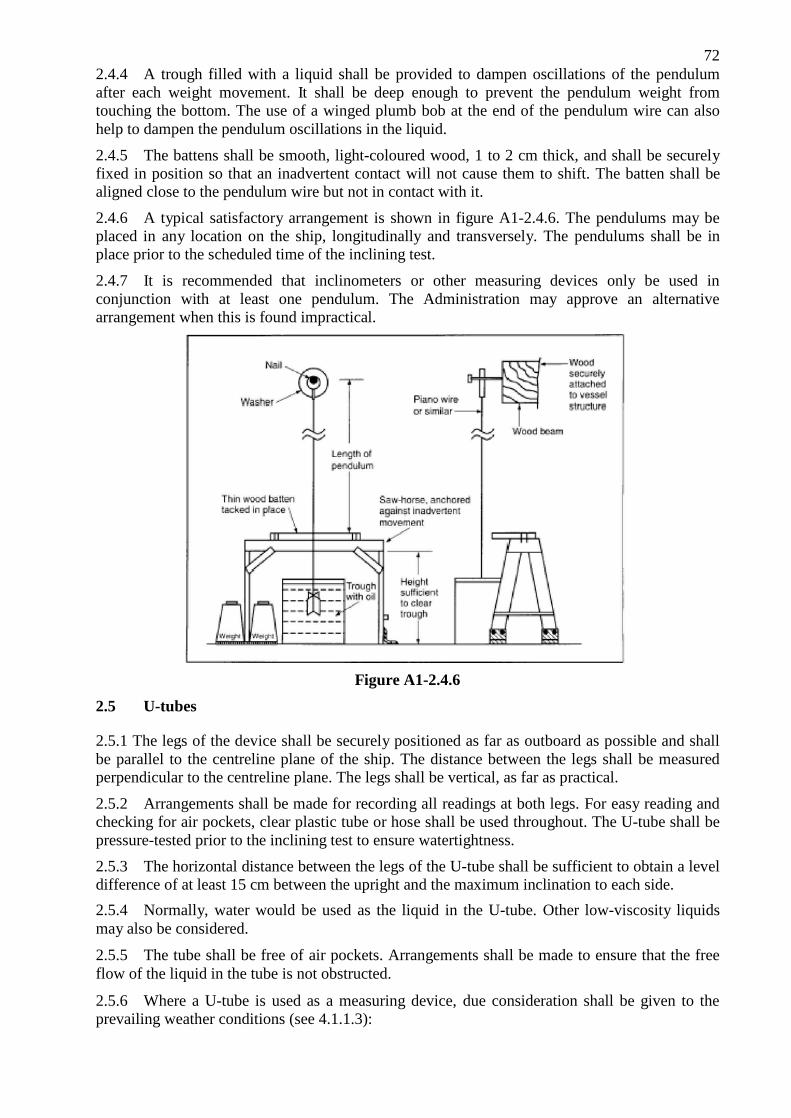
72 2.4.4 A trough filled with a liquid shall be provided to dampen oscillations of the pendulum after each weight movement. It shall be deep enough to prevent the pendulum weight from touching the bottom. The use of a winged plumb bob at the end of the pendulum wire can also help to dampen the pendulum oscillations in the liquid.
2.4.5 The battens shall be smooth, light-coloured wood, 1 to 2 cm thick, and shall be securely fixed in position so that an inadvertent contact will not cause them to shift. The batten shall be aligned close to the pendulum wire but not in contact with it.
2.4.6 A typical satisfactory arrangement is shown in figure A1-2.4.6. The pendulums may be placed in any location on the ship, longitudinally and transversely. The pendulums shall be in place prior to the scheduled time of the inclining test.
2.4.7 It is recommended that inclinometers or other measuring devices only be used in conjunction with at least one pendulum. The Administration may approve an alternative arrangement when this is found impractical.
2.5 U-tubes
Figure A1-2.4.6
2.5.1 The legs of the device shall be securely positioned as far as outboard as possible and shall be parallel to the centreline plane of the ship. The distance between the legs shall be measured perpendicular to the centreline plane. The legs shall be vertical, as far as practical.
2.5.2 Arrangements shall be made for recording all readings at both legs. For easy reading and checking for air pockets, clear plastic tube or hose shall be used throughout. The U-tube shall be pressure-tested prior to the inclining test to ensure watertightness.
2.5.3 The horizontal distance between the legs of the U-tube shall be sufficient to obtain a level difference of at least 15 cm between the upright and the maximum inclination to each side.
2.5.4 Normally, water would be used as the liquid in the U-tube. Other low-viscosity liquids may also be considered.
2.5.5 The tube shall be free of air pockets. Arrangements shall be made to ensure that the free flow of the liquid in the tube is not obstructed.
2.5.6 Where a U-tube is used as a measuring device, due consideration shall be given to the prevailing weather conditions (see 4.1.1.3):

73 .1 if the U-tube is exposed to direct sunlight, arrangements shall be made to avoid
temperature differences along the length of the tube;
.2 if temperatures below 0°C are expected, the liquid shall be a mixture of water and an anti-freeze additive; and
.3 where heavy rain squalls can be expected, arrangements shall be made to avoid additional water entering the U-tube.
2.6 Inclinometers
The use of inclinometers shall be subject to at least the following recommendations:
.1 the accuracy shall be equivalent to that of the pendulum;
.2 the sensitivity of the inclinometer shall be such that the non-steady heeling angle
of the ship can be recorded throughout the measurement;
.3 the recording period shall be sufficient to accurately measure the inclination. The recording capacity shall be generally sufficient for the whole test;
.4 the instrument shall be able to plot or print the recorded inclination angles on
paper;
.5 the instrument shall have linear performance over the expected range of inclination angles;
.6 the instrument shall be supplied with the manufacturer’s instructions giving details of calibration, operating instructions, etc.; and
.7 it shall be possible to demonstrate the required performance to the satisfaction of the Administration during the inclining test.

74
3 EQUIPMENT REQUIRED
Besides the physical equipment necessary such as the inclining weights, pendulums, small boat, etc., the following are necessary and shall be provided by or made available to the person in charge of the inclining:
.1 engineering scales for measuring pendulum deflections (rules shall be subdivided sufficiently to achieve the desired accuracy;
.2 sharp pencils for marking pendulum deflections;
.3 chalk for marking the various positions of the inclining weights;
.4 a sufficiently long measuring tape for measuring the movement of the weights and locating different items on board;
.5 a sufficiently long sounding tape for sounding tanks and taking freeboard readings;
.6 one or more well maintained specific gravity hydrometers with range sufficient to cover 0.999 to 1.030, to measure the specific gravity of the water in which the ship is floating (a hydrometer for measuring specific gravity of less than 1.000 may be needed in some locations);
.7 other hydrometers as necessary to measure the specific gravity of any liquids on board;
.8 graph paper to plot inclining moments versus tangents;
.9 a straight edge to draw the measured waterline on the lines drawing;
.10 a pad of paper to record data;
.11 an explosion-proof testing device to check for sufficient oxygen and absence of lethal gases in tanks and other closed spaces such as voids and cofferdams;
.12 a thermometer; and
.13 draught tubes (if necessary). 4 TEST PROCEDURE
The inclining experiment, the freeboard/draught readings and the survey may be conducted in any order and still achieve the same results. If the person conducting the inclining test is confident that the survey will show that the ship is in an acceptable condition and there is the possibility of the weather becoming unfavourable, then it is suggested that the inclining be performed first and the survey last. If the person conducting the test is doubtful that the ship is complete enough for the test, it is recommended that the survey be performed first since this could invalidate the entire test, regardless of the weather conditions. It is very important that all weights, the number of people on board, etc., remain constant throughout the test.
4.1 Initial walk through and survey
The person responsible for conducting the inclining test shall arrive on board the ship well in advance of the scheduled time of the test to ensure that the ship is properly prepared for the test. If the ship to be inclined is large, a preliminary walk through may need to be done the day preceding the actual incline. To ensure the safety of personnel conducting the walk through, and to improve the documentation of surveyed weights and deficiencies, at least two persons shall make the initial walk through. Things to check include: all compartments are open, clean, and
75 dry, tanks are well ventilated and gas-free, movable or suspended items are secured and their position documented, pendulums are in place, weights are on board and in place, a crane or other method for moving weights is available, and the necessary plans and equipment are available. Before beginning the inclining test, the person conducting the test shall:
.1 consider the weather conditions. The combined adverse effect of wind, current and sea may result in difficulties or even an invalid test due to the following:
.1 inability to accurately record freeboards and draughts;
.2 excessive or irregular oscillations of the pendulums;
.3 variations in unavoidable superimposed heeling moments.
In some instances, unless conditions can be sufficiently improved by moving the ship to a better location, it may be necessary to delay or postpone the test. Any significant quantities of rain, snow, or ice shall be removed from the ship before the test. If bad weather conditions are detected early enough and the weather forecast does not call for improving conditions, the Administration representative shall be advised prior to departure from the office and an alternative date scheduled;
.2 make a quick overall survey of the ship to make sure the ship is complete enough to conduct the test and to ensure that all equipment is in place. An estimate of items which will be outstanding at the time of the inclining test shall be included as part of any test procedure submitted to the Administration. This is required so that the Administration representative can advise the shipyard/naval architect if in their opinion the ship will not be sufficiently complete to conduct the incline and that it shall be rescheduled. If the condition of the ship is not accurately depicted in the test procedure and at the time of the inclining test the Administration representative considers that the ship is in such condition that an accurate incline cannot be conducted, the representative may refuse to accept the incline and require that the incline be conducted at a later date;
.3 enter all empty tanks after it is determined that they are well ventilated and gas- free to ensure that they are dry and free of debris. Ensure that any pressed-up tanks are indeed full and free of air pockets. The anticipated liquid loading for the incline shall be included in the procedure required to be submitted to the Administration;
.4 survey the entire ship to identify all items which need to be added to the ship, removed from the ship, or relocated on the ship to bring the ship to the lightship condition. Each item shall be clearly identified by weight and vertical and longitudinal location. If necessary, the transverse location shall also be recorded. The inclining weights, the pendulums, any temporary equipment and dunnage, and the people on board during the inclining test are all among the weights to be removed to obtain the lightship condition. The person calculating the lightship characteristics from the data gathered during the incline and survey and/or the person reviewing the inclining test may not have been present during the test and shall be able to determine the exact location of the items from the data recorded and the ship’s drawings. Any tanks containing liquids shall be accurately sounded and the soundings recorded;
.5 it is recognized that the weight of some items on board, or that are to be added, may have to be estimated. If this is necessary, it is in the best interest of safety to be on the safe side when estimating, so the following rules of thumb shall be followed:

76 .1 when estimating weights to be added:
1.1 estimate high for items to be added high in the ship; and 1.2 estimate low for items to be added low in the ship;
.2 when estimating weights to be removed:
2.1 estimate low for items to be removed from high in the ship; and
2.2 estimate high for items to be removed from low in the ship;
.3 when estimating weights to be relocated:
3.1 estimate high for items to be relocated to a higher point in the ship;
and
3.2 estimate low for items to be relocated to a lower point in the ship. 4.2 Freeboard/draught readings
4.2.1 Freeboard/draught readings shall be taken to establish the position of the waterline in order to determine the displacement of the ship at the time of the inclining test. It is recommended that at least five freeboard readings, approximately equally spaced, be taken on each side of the ship or that all draught marks (forward, midship, and aft) be read on each side of the ship. Draught mark readings shall be taken to assist in determining the waterline defined by freeboard readings, or to verify the vertical location of draught marks on ships where their location has not been confirmed. The locations for each freeboard reading shall be clearly marked. The longitudinal location along the ship shall be accurately determined and recorded since the (moulded) depth at each point will be obtained from the ship’s lines. All freeboard measurements shall include a reference note clarifying the inclusion of the coaming in the measurement and the coaming height.
4.2.2 Draught and freeboard readings shall be read immediately before or immediately after the inclining test. Weights shall be on board and in place and all personnel who will be on board during the test, including those who will be stationed to read the pendulums, shall be on board and in location during these readings. This is particularly important on small ships. If readings are made after the test, the ship shall be maintained in the same condition as during the test. For small ships, it may be necessary to counterbalance the list and trim effects of the freeboard measuring party. When possible, readings shall be taken from a small boat.
4.2.3 A small boat shall be available to aid in the taking of freeboard and draught mark readings. It shall have low freeboard to permit accurate observation of the readings.
4.2.4 The specific gravity of the flotation water shall be determined at this time. Samples shall be taken from a sufficient depth of the water to ensure a true representation of the flotation water and not merely surface water, which could contain fresh water from run-off of rain. A hydrometer shall be placed in a water sample and the specific gravity read and recorded. For large ships, it is recommended that samples of the flotation water be taken forward, midship, and aft and the readings averaged. For small ships, one sample taken from midships shall be sufficient. The temperature of the water shall be taken and the measured specific gravity corrected for deviation from the standard, if necessary. A correction to water specific gravity is not necessary if the specific gravity is determined at the inclining experiment site. Correction is necessary if specific gravity is measured when sample temperature differs from the temperature at the time of the inclining (e.g., if check of specific gravity is done at the office).
4.2.5 A draught mark reading may be substituted for a given freeboard reading at that longitudinal location if the height and location of the mark have been verified to be accurate by a keel survey while the ship was in dry dock.
77 4.2.6 A device, such as a draught tube, can be used to improve the accuracy of freeboard/draught readings by damping out wave action.
4.2.7 The dimensions given on a ship’s lines drawing are normally moulded dimensions. In the case of depth, this means the distance from the inside of the bottom shell to the inside of the deck plate. In order to plot the ship’s waterline on the lines drawing, the freeboard readings shall be converted to moulded draughts. Similarly, the draught mark readings shall be corrected from extreme (bottom of keel) to moulded (top of keel) before plotting. Any discrepancy between the freeboard/draught readings shall be resolved.
4.2.8 The mean draught (average of port and starboard readings) shall be calculated for each of the locations where freeboard/draught readings are taken and plotted on the ship’s lines drawing or outboard profile to ensure that all readings are consistent and together define the correct waterline. The resulting plot shall yield either a straight line or a waterline which is either hogged or sagged. If inconsistent readings are obtained, the freeboards/draughts shall be retaken.
4.3 The incline
4.3.1 Prior to any weight movements the following shall be checked:
.1 the mooring arrangement shall be checked to ensure that the ship is floating
freely (this shall be done just prior to each reading of the pendulums);
.2 the pendulums shall be measured and their lengths recorded. The pendulums shall be aligned so that when the ship heels, the wire will be close enough to the batten to ensure an accurate reading but will not come into contact with the batten. The typical satisfactory arrangement is shown in figure A1-2.4.6;
.3 the initial position of the weights is marked on the deck. This can be done by tracing the outline of the weights on the deck; .4 the communications arrangement is adequate; and .5 all personnel are in place.
4.3.2 A plot shall be run during the test to ensure that acceptable data are being obtained. Typically, the abscissa of the plot will be heeling moment W(x) (weight times distance x) and the ordinate will be the tangent of the heel angle (deflection of the pendulum divided by the length of the pendulum). This plotted line does not necessarily pass through the origin or any other particular point for no single point is more significant than any other point. A linear regression analysis is often used to fit the straight line. The weight movements shown in figure A2-4.3.2-1 give a good spread of points on the test plot.

78
Figure A1-4.3.2-1
The plotting of all the readings for each of the pendulums during the inclining experiment aids in the discovery of bad readings. Since W(x)/tan ö shall be constant, the plotted line shall be straight. Deviations from a straight line are an indication that there were other moments acting on the ship during the inclining. These other moments shall be identified, the cause corrected, and the weight movements repeated until a straight line is achieved. Figures A1-4.3.2-2 to A1-4.3.2-5 illustrate examples of how to detect some of these other moments during the inclining, and a recommended solution for each case. For simplicity, only the average of the readings is shown on the inclining plots.
Figure A1-4.3.2-2 Figure A1-4.3.2-3

79
Figure A1-4.3.2-4 Figure A1-4.3.2-5

80
4.3.3 Once everything and everyone is in place, the zero position shall be obtained and the remainder of the experiment conducted as quickly as possible, while maintaining accuracy and proper procedures, in order to minimize the possibility of a change in environmental conditions during the test.
4.3.4 Prior to each pendulum reading, each pendulum station shall report to the control station when the pendulum has stopped swinging. Then, the control station will give a “standby” warning and then a “mark” command. When “mark” is given, the batten at each position shall be marked at the location of the pendulum wire. If the wire was oscillating slightly, the centre of the oscillations shall be taken as the mark. If any of the pendulum readers does not think the reading was a good one, the reader shall advise the control station and the point shall be retaken for all pendulum stations. Likewise, if the control station suspects the accuracy of a reading, it shall be repeated for all the pendulum stations. Next to the mark on the batten shall be written the number of the weight movement, such as zero for the initial position and one to seven for the weight movements.
4.3.5 Each weight movement shall be made in the same direction, normally transversely, so as not to change the trim of the ship. After each weight movement, the distance the weight was moved (centre to centre) shall be measured and the heeling moment calculated by multiplying the distance by the amount of weight moved. The tangent is calculated for each pendulum by dividing the deflection by the length of the pendulum. The resultant tangents are plotted on the graph. Provided there is good agreement among the pendulums with regard to the tan ö value, the average of the pendulum readings may be graphed instead of plotting each of the readings.
4.3.6 Inclining data sheets shall be used so that no data are forgotten and so that the data are clear, concise, and consistent in form and format. Prior to departing the ship, the person conducting the test and the Administration representative shall initial each data sheet as an indication of their concurrence with the recorded data.
81
ANNEX 2
RECOMMENDATIONS FOR SKIPPERS OF FISHING VESSELS ON ENSURING A VESSEL’S ENDURANCE IN CONDITIONS OF ICE FORMATION
1 Prior to departure
1.1 Firstly, the skipper shall, as in the case of any voyages in any season, ensure that the vessel is generally in a seaworthy condition, giving full attention to basic requirements such as:
.1 loading of the vessel within the limits prescribed for the season (paragraph 1.2.1 below);
.2 weathertightness and reliability of the devices for closing cargo and access hatches, outer doors and all other openings in the decks and superstructures of the vessel and the watertightness of the sidescuttles and of ports or similar openings in the sides below the freeboard deck to be checked;
.3 condition of the freeing ports and scuppers as well as operational reliability of their closures to be checked;
.4 emergency and life-saving appliances and their operational reliability;
.5 operational reliability of all external and internal communication equipment; and
.6 condition and operational reliability of the bilge and ballast pumping systems. 1.2 Further, with special regard to possible ice accretion, the skipper shall:
.1 consider the most critical loading condition against approved stability documents
with due regard to fuel and water consumption, distribution of supplies, cargoes and fishing gear and with allowance for possible ice accretion;
.2 be aware of the danger in having supplies and fishing gear stored on open weather deck spaces due to their large ice accretion surface and high centre of gravity;
.3 ensure that a complete set of warm clothing for all members of the crew is available on the vessel as well as a complete set of hand tools and other appliances for combating ice accretion, a typical list thereof for small vessels is shown in section 4 of this annex;
.4 ensure that the crew is acquainted with the location of means for combating ice accretion, as well as the use of such means, and that drills are carried out so that members of the crew know their respective duties and have the necessary practical skills to ensure the vessel’s endurance under conditions of ice accretion;
.5 acquaint himself with the meteorological conditions in the region of fishing grounds and en route to the place of destination; study the synoptical maps of this region and weather forecasts; be aware of warm currents in the vicinity of the fishing grounds, of the nearest coastline relief, of the existence of protected bays and of the location of ice fields and their boundaries; and
.6 acquaint himself with the timetable of the radio stations transmitting weather forecasts and warnings of the possibility of ice accretion in the area of the relevant fishing grounds.

82
2 At sea
2.1 During the voyage and when the vessel is on the fishing grounds, the skipper shall keep himself informed on all long-term and short-term weather forecasts and shall arrange for the following systematic meteorological observations to be systematically recorded:
.1 temperatures of the air and of the sea surface;
.2 wind direction and force;
.3 direction and height of waves and sea state;
.4 atmospheric pressure, air humidity; and
.5 frequency of splashing per minute and the intensity of ice accumulation on different parts of the vessel per hour.
2.2 All observed data shall be recorded in the vessel’s log-book. The skipper shall compare the weather forecasts and icing charts with actual meteorological conditions, and shall estimate the probability of ice formation and its intensity.
2.3 When the danger of ice formation arises, the following measures shall be taken without delay:
.1 all the means of combating ice formation shall be ready for use;
.2 all the fishing operations shall be stopped, the fishing gear shall be taken on board and placed in the under-deck spaces. If this cannot be done all the gear shall be fastened for storm conditions on its prescribed place. It is particularly dangerous to leave the fishing gear suspended since its surface for ice formation is large and the point of suspension is generally located high;
.3 barrels and containers with fish, packing, all gear and supplies located on deck as well as portable mechanisms shall be placed in closed spaces as low as possible and firmly lashed;
.4 all cargoes in holds and other compartments shall be placed as low as possible and firmly lashed;
.5 the cargo booms shall be lowered and fastened;
.6 deck machinery, hawser reels and boats shall be covered with duck covers;
.7 lifelines shall be fastened on deck;
.8 freeing ports fitted with covers shall be brought into operative condition, all objects located near scuppers and freeing ports and preventing water drainage from deck shall be taken away;
.9 all cargo and companion hatches, manhole covers, weathertight outside doors in superstructures and deck-houses and portholes shall be securely closed in order to ensure complete weathertightness of the vessel, access to the weather deck from inner compartments shall be allowed only through the superstructure deck;
.10 a check shall be carried out as to whether the amount of water ballast on board and its location is in accordance with that recommended in “Stability Standard to

83 skippers”; if there is sufficient freeboard, all the empty bottom tanks fitted with ballast piping shall be filled with seawater;
.11 all fire-fighting, emergency and life-saving equipment shall be ready for use;
.12 all drainage systems shall be checked for their effectiveness;
.13 deck lighting and searchlights shall be checked;
.14 a check shall be carried out to make sure that each member of the crew has warm clothing; and
.15 reliable two-way radio communication with both shore stations and other vessels shall be established; radio calls shall be arranged for set times.
2.4 The skipper shall seek to take the vessel away from the dangerous area, keeping in mind that the lee edges of icefields, areas of warm currents and protected coastal areas are a good refuge for the vessel during weather when ice formation occurs.
2.5 Small fishing vessels on fishing grounds shall keep nearer to each other and to larger vessels.
2.6 It shall be remembered that the entry of the vessel into an icefield presents certain danger to the hull, especially when there is a high sea swell. Therefore the vessel shall enter the icefield at a right angle to the icefield edge at low speed without inertia. It is less dangerous to enter an icefield bow to the wind. If a vessel must enter an icefield with the wind on the stern, the fact that the edge of the ice is more dense on the windward side shall be taken into consideration. It is important to enter the icefield at the point where the ice floes are the smallest.
3 During ice formation
3.1 If in spite of all measures taken the vessel is unable to leave the dangerous area, all means available for removal of ice shall be used as long as it is subjected to ice formation.
3.2 Depending on the type of vessel, all or many of the following ways of combating ice formation may be used:
.1 removal of ice by means of cold water under pressure;
.2 removal of ice with hot water and steam; and
.3 breaking up of ice with ice crows, axes, picks, scrapers, or wooden sledge-hammers and clearing it with shovels.
3.3 When ice formation begins, the skipper shall take into account the recommendations listed below and ensure their strict fulfilment:
.1 report immediately ice formation to the shipowner and establish with him constant radio communication;
.2 establish radio communication with the nearest vessels and ensure that it is maintained;
.3 do not allow ice formation to accumulate on the vessel, immediately take steps to remove from the vessel’s structures even the thinnest layer of ice and ice sludge from the upper deck;
.4 check constantly the vessel’s stability by measuring the roll period of the vessel during ice formation. If the rolling period increases noticeably, immediately take

84 all possible measures in order to increase the vessel’s stability;
.5 ensure that each member of the crew working on the weather deck is warmly
dressed and wears a safety line securely attached to the guardrail;
.6 bear in mind that the work of the crew on ice clearing entails the danger of frost bite. For this reason it is necessary to make sure that members of the crew working on deck are replaced periodically;
.7 keep the following structures and gears of the vessel first free from ice:
7.1 aerials;
7.2 running and navigational lights;
7.3 freeing ports and scuppers;
7.4 lifesaving craft;
7.5 stays, shrouds, masts and rigging;
7.6 doors of superstructures and deck-houses; and
7.7 windlass and hawse holes;
.8 remove the ice from large surfaces of the vessel, beginning with the upper structures (such as bridges, deck-houses, etc.), because even a small amount of ice on them causes a drastic worsening of the vessel’s stability;
.9 when the distribution of ice is not symmetrical and a list develops, the ice must be cleared from the lower side first. Bear in mind that any correction of the list of the vessel by pumping fuel or water from one tank to another may reduce stability during the process when both tanks are slack;
.10 when a considerable amount of ice forms on the bow and a trim appears, ice must be quickly removed. Water ballast may be redistributed in order to decrease the trim;
.11 clear ice from the freeing ports and scuppers in due time in order to ensure free drainage of the water from the deck;
.12 check regularly for water accumulation inside the hull;
.13 avoid navigating in following seas since this may drastically worsen the vessel’s stability;
.14 register in the vessel’s log-book the duration, nature and intensity of ice formation, amount of ice on the vessel, measures taken to combat ice formation and their effectiveness; and
.15 if, in spite of all the measures taken to ensure the vessel’s endurance in conditions of ice formation, the crew is forced to abandon the vessel and embark on life- saving craft (lifeboats, rafts) then, in order to preserve their lives, it is necessary to do all possible to provide all the crew with warm clothing or special bags as well as to have a sufficient number of lifelines and bailers for speedy bailing out of water from the life-saving craft.
85
4 List of equipment and hand tools
A typical list of equipment and hand tools required for combating ice formation:
.1 ice crows or crowbars;
.2 axes with long handles;
.3 picks;
.4 metal scrapers;
.5 metal shovels;
.6 wooden sledge-hammers;
.7 fore and aft lifelines to be rigged each side of the open deck fitted with travellers
to which lizards can be attached.
Safety belts with spring hooks shall be provided for no less than 50% of the members of the crew (but not less than 5 sets), which can be attached to the lizards.
Notes: 1 The number of hand tools and lifesaving appliances may be increased, at the shipowner’s discretion.
2 Hoses which may be used for ice combating shall be readily available on board.