intra-laminar damage evolution in a composite grid ... · pdf fileabstract: in this paper the...
TRANSCRIPT

Copyright © 2013 Tech Science Press SDHM, vol.9, no.1, pp.43-66, 2013
Intra-laminar Damage Evolution in a Composite GridStructure Representative Volume Element under
Compression Load
A. Riccio1, F. Caputo1 and N. Tessitore2
Abstract: In this paper the mechanical behavior of composites grid structureshas been numerically investigated. The evolution of fibers and matrix crackinghas been simulated by adopting a progressive damage approach. The Hashin fail-ure criteria and ply properties degradation rules have been adopted to simulate thedegradation at ply level. Non-linear analyses on a Representative Volume Elementof the composite grid structure have been performed to account for its compressionbehavior.
Keywords: Progressive damage, grid structures, FEM, buckling, RVE.
1 Introduction
Due to the relevant difficulties in the manufacturing process, for many years thecomposite grid structures have not been considered as a valid alternative to stan-dard aerospace structural concepts. However, in the last years, remarkable pro-gresses have been made in the manufacturing of composite grids so that they are be-ing strongly reconsidered for aerospace applications (Vasiliev, Barynin, and Rasin2001; Vasiliev, and Razin 2006; Hou, and Gramoll 2000). Grid structures are char-acterized by a shell structure (or skin) supported by a lattice pattern (or grid) of rigidand interconnected ribs (Buragohain, and Velmurugan 2011). Fibrous compositematerials seem to be particularly suitable for grid structure applications due to theirhigh directionality which allows the material’s stiffness and strength to be drivenalong the rib directions according to stresses gradients. The chance to easily auto-mate the manufacturing process is another advantage of composite grid structures.As an example, the automated filament winding manufacturing process is widelyadopted for the manufacturing of revolution grid structures used for aerospace ap-plications (Huybrechts, Meink, Wegner, and Ganley 2002). Nevertheless, one ma-
1 The Second University of Naples - DIAM, Naples, Italy.2 AVIO, Colleferro (Rome), Italy.

44 Copyright © 2013 Tech Science Press SDHM, vol.9, no.1, pp.43-66, 2013
jor drawback, which can negatively influence the introduction of the compositegrid structure into industry, is the lack of understanding about the onset and prop-agation of damage within the grids components (ribs and skin) under compressiveloading conditions which may be very critical for the integrity of the single compo-nents and for the interface skin-ribs. The compressive behavior of composites gridstructures has been investigated by Kidane, Helms, Pang, and Woldesenbet (2003)and by Wodesenbet, Kidane, and Pang (2003) where an analytical model for de-termination of the stiffness of a grid stiffened composite cylindrical shell has beendeveloped by taking into account a grid representative volume element (RVE). Wellestablished stress based failure criteria can be found in literature which account forthe damage on-set in terms of fiber and matrix cracking in composite materials.The Hashin-Rotem criterion (Hashin 1980; Hashin, and Rotem 1973), being ableto distinguish between fiber breakage and matrix cracking, seems to be the mostreliable one in interpreting the material physical behavior. Other failure criteria(Yamada, and Sun 1978; Christensen 1988; Tsai, and Wu 1971; Feng 1991), evenif effective in FE implementation, lack in terms of composite failure mechanismdescription.
In order to simulate the damage evolution, a progressive failure procedure involv-ing failure criteria and material properties degradation rules is needed. The basicdescription of a progressive failure procedure is presented by Ochoa, and Reddy(1992); Sleight, Knight, and Wang (1997) and Sleight (1999) where the applica-tion of the failure criteria and the description of the material properties after thedamage detection are appointed as key aspects. In general three categories of ma-terial degradation models can be identified: instantaneous unloading (Murray, andSchwer 1990), gradual unloading (Petit, and Waddoups 1969; Sandhu 1974; Nahas1986) and constant stress at ply failure (Hahn, and Tsai 1983). Progressive failureanalyses on composites grid structures have been performed by He, and He (2010)and by Zhang, Chen, and Ye (2008) where the combinations Tsai-Wu failure cri-terion /Chang stiffness degradation criterion and Hashin criterion /instantaneousdegradation rules have been respectively used, however, no information is givenabout the damage evolution under compressive loading conditions. Additionalexamples of progressive failure analysis are reported in Katerelos, Kashtalyan,Soutis, and Galiotis (2008), where the effect of matrix cracking on the behaviorof glass/epoxy laminates loaded statically in tension has been investigated, and inSoutis, and Kashtalyan (2011) where the Equivalent Constraint Model (ECM) is ap-plied to predict residual stiffness properties of polymer matrix cross-ply laminatessubjected to in-plane biaxial loading and damaged by matrix cracks. An interestingreview of some progression damage models is presented in Kashtalyan, and Soutis(2005) where the failure process of composite laminate involving sequential accu-

Intra-laminar Damage Evolution 45
mulation of matrix, fiber damage and delaminations is investigated. Other recentworks on inter-laminar stress analysis, multiscale modeling and composite dam-age characterization are described respectively in Yiming, Sheng and Yejie (2008),in Raimondo and Aliabadi (2009), in Balhi, Vrellos, Drinkwater, Guild, Ogin andSmith (2006) and in Forghani, Zobeiry, Vaziri, Poursartip,and Ellyin (2009). Aninteresting work considering meshfree modeling and homogenization of 3D orthog-onal woven composites has been developed by Wen and Alibadi (2011).
The aim of the present paper, which describes the continuation of the researchwork on composite grid structures introduced in Tessitore, and Riccio (2005), is toperform a numerical investigation of the failure mechanisms and their interactionin composite grid structures, under compression loading condition, focusing on aRepresentative Volume Element (RVE). RVE, of course, cannot provide indicationsabout specific complex geometry or boundary conditions of the grids but has thestrong advantage to easily represent the basic structural behavior of grids compo-nents with onset and propagation of damage in ribs and skin. The compressivestructural behavior of the grid RVE has been numerically investigated by meansof a geometrically non-linear Finite Element approach (Caputo, Lamanna, and So-prano 2006; Armentani, Calì, Caputo, Cricrì, and Esposito 2006; Caputo, Esposito,Perugini, and Santoro 2002), able to account for fibers and matrix damage onsetand propagation, already applied and validated against experimental results for thestudy of composite joints (Riccio, and Marciano 2005; Riccio 2005), flat delam-inated composite panels (Riccio, and Pietropaoli 2008) and stiffened delaminatedcomposite panels (Pietropaoli, and Riccio 2011). This numerical procedure, basedon the Hashin’s failure criteria to detect the damage on-set and on the ply discountmaterial properties degradation rules to follow the damage progression, has beenimplemented in the research oriented FEM code B2000 (Merazzi, and de Boer1994). In order to analyze the damage onset and progression in the skin and inthe ribs, two different types of RVE have been considered, with skin and withoutskin respectively. Numerical analyses performed on these RVE’s, with and withoutconsidering the damage progression allowed to investigate the failure mechanismsin the skin and in the ribs separately. The obtained results have been compared andassessed in order to evaluate the influence of damage onset and progression on thecompression behavior of the analyzed grid structures RVE. The damage status overthe RVE has also been assessed to give a realistic representation of the damage ini-tiation and propagation during the loading process. In the next sections, the theorybehind the proposed progressive failure approach is described in detail, togetherwith the numerical applications. Then the most relevant results are presented andcritically discussed.

46 Copyright © 2013 Tech Science Press SDHM, vol.9, no.1, pp.43-66, 2013
2 Theoretical Background
The simulation of the damage on-set and propagation in composite structures needsthe simultaneous application of stress based failure criteria and material propertiesdegradation rules. In the next subsection the theory behind the failure criteria andthe material properties degradation rules, used in the proposed model, is describedin details.
2.1 Failure Criteria
The Hashin’s failure criteria have been selected for the present application and im-plemented in the B2000 FEM code, since, such criteria, using distinct polynomialsassociated to different failure modes, are able to separately predict the fiber break-age and the matrix cracking for each layer. As a first approximation only the fiberand matrix failure mechanisms have been included in the adopted FEM tool. Theinstability at fiber level, extensively studied by Berbinau, Soutis, and Guz (1999),has been taken into account through a specific fiber kinking failure criterion whilethe delamination onset and growth have not been included in the present model,which, as a matter of the facts, has been used to perform a basic, and limited, in-vestigation on intra-laminar composite grid structures failure mechanisms focusingon some of the main aspects characterizing the failure of pristine grid structuresunder compression. Hence in our analyses, the following failure mechanisms inskin and ribs and the associated failure criteria have been considered (σi j are thestress components in the ij direction and Si j,Yt ,Xt ,Yc,Xc are the material strengthsof the ply):
Matrix tens. fail. (σyy > 0)(σyy
Yt
)2
+(
σxy
Sxy
)2
+(
σyz
Syz
)2
≥ 1 (1)
Matrix comp. fail. (σyy < 0)(σyy
Yc
)2
+(
σxy
Sxy
)2
+(
σxz
Syz
)2
≥ 1 (2)
Fibre tens. fail. σxx > 0(σxx
Xt
)2
+(
σxy
Sxy
)2
+(
σxz
Sxz
)2
≥ 1 (3)
Fibre comp. fail. σxx < 0(σxx
Xc
)≥ 1 (4)

Intra-laminar Damage Evolution 47
Fib-mat sh-out fail. σxx < 0(σxx
Xt
)2
+(
σxy
Sxy
)2
+(
σxz
Sxz
)2
≥ 1 (5)
Fibre-Kinking failure σxx < 0(σxx
Xc
)2
+(
σxz
Sxz
)2
≥ 1 (6)
In order to find the ply strengths starting from the fibre and matrix properties, mi-cromechanics relations (Stellbrink Kuno 1996) have been adopted.
2.2 Material properties degradation rules
Material properties degradation rules have been applied to take into account thematerial behaviour of each layer after damage occurrence. This was needed inorder to perform a progressive failure analysis up to the global failure, which isassumed to occur when the structure is not able to withstand the load anymoredue to the presence of extended degraded areas. For each of the above describedfailure modes, according to the ply discount approach, an appropriate propertiesdegradation, which roughly reflects the physics of the damage mechanisms, hasbeen introduced.
Matrix tensile and compression failure
Ey = k ·Ey
Ez = k ·Ez
Gyz = k ·Gyz
(7)
Fiber tensile and compression failure
Ex = k ·Ex
Gxy = Gyz
Gxz = Gyz
(8)
Fiber-matrix shear-out failure
Gxy = Gyz
Gxz = Gyz(9)
Fiber-Kinking failure
Ex = k ·Ex Gxy = k ·Gyz
Ey = k ·Ey Gxz = k ·Gyz
Ez = k ·Ez Gyz = k ·Gyz
(10)

48 Copyright © 2013 Tech Science Press SDHM, vol.9, no.1, pp.43-66, 2013
where k is a degradation factor and the over-lined properties indicate the corre-sponding degraded composite ply material properties. Indeed several formulationscan be found in literature which propose different relations for k as a function ofthe stress state. However, as a first approximation, in this paper the instantaneousunloading approach has been adopted since it has been proved to effectively mimicthe brittle material behavior. The instantaneous unloading approach requires thatk=0, however a non-zero value for the factor k has been adopted to avoid conver-gence problems. The composite ply properties have been evaluated starting fromthe fiber and matrix elastic properties by means of micromechanics relations simi-larly to what have been done by Riks (1984).
3 Finite Element Implementation
The failure criteria and the properties degradation rules described in the previoussection have been implemented in the Finite Element Code B2000 (Merazzi, andde Boer 1994) which is a fully customizable FEM code particularly suitable forresearch purposes. In particular a progressive damage finite element able to simu-late the damage onset and progression has been developed. This finite element isembedded within the B2000 continuation macro-processor which adopts the con-tinuation method of Riks (Gan, Gibson, and Newaz 2004) to perform geometricallynon-linear analyses. A flowchart describing the progressive damage procedure, im-plemented in the FEM code B2000, is shown in Figure 1.
According to the progressive damage procedure, after the application of the initialloading condition, the stiffness matrix, the force vector and stresses are calculated.Then a check of the Hashin failure criteria is performed. If damage is detected,the material properties are degraded according to the properties degradation rules.Convergence is checked and the loop is repeated until the complete failure hasbeen detected. Additional B2000 modules have been developed which are able tohandle the huge amount of data coming from the computations (damage locationand failure mode for each layer, for each element at each time step).
An integer number has been associated to each failure mode according to Table 1.
This association makes it possible to visualize the damage status, location and fail-ure mechanism as a contour plot over the defined integer range on the un-deformedor deformed structural configurations.
4 Numerical Application
The implemented progressive damage approach has been applied to a Represen-tative Volume Element of a composite grid structure with and without skin. Inthis section the RVE model is described in detail and the results of the non-linear

Intra-laminar Damage Evolution 49
Input file
INPUT PROCESSOR
Continuation macro-processor
Initial load conditionProgressive Damage Element
Stiffness matrix, force vector and Cauchy
stress transformation
Degradation of material properties
New step?
Failure check
Convergence?
Max iteration?
Complete failure
no
no
yes
yes
New step (ncrease the load) yes
New iteration (same steps) no
no
yes
NON-LINEAR REACTION FORCES
MODULE
DAMAGE DATA MANIPULATION
MODULE
Output
Input file
INPUT PROCESSOR
Continuation macro-processor
Initial load conditionProgressive Damage Element
Stiffness matrix, force vector and Cauchy
stress transformation
Degradation of material properties
New step?New step?
Failure checkFailure check
Convergence?Convergence?
Max iteration?Max iteration?
Complete failure
no
no
yes
yes
New step (ncrease the load) yes
New iteration (same steps) no
no
yes
NON-LINEAR REACTION FORCES
MODULE
DAMAGE DATA MANIPULATION
MODULE
Output
Figure 1: Schematic description of the non linear procedure adopted with damagepropagation
Table 1: Numbering of the failure mode in the B2000 code
Failure Mode B2000 output
Undamaged ply 2
Matrix Failure 5
Fibre Failure 6
Shear-out+fibre+matrix failure 7
Kinking Failure 8
Shear-out+matrix failure 9
Matrix+fibre failure 10
Completely failed ply 11

50 Copyright © 2013 Tech Science Press SDHM, vol.9, no.1, pp.43-66, 2013
analyses are presented.
4.1 Model geometry, boundary conditions and FEM model
An example of cylindrical composite grid structure obtained by filament windingis shown in Figure 2.
RVE
Figure 2: Identification of a Representative Volume Element
The repetitiveness of this structure allows to easily define a Representative VolumeElement (RVE). For high Diameter/RVE length ratio (see Figure 3) a simplifiedplain RVE model can be considered. Also the boundary conditions can be sim-plified by considering a uniaxial compressive load as representative of the actionsundergone by the RVE as a part of the global composite grid structure.
These simplifications can be considered acceptable for the purposes of this studywhich is aimed to perform a preliminary investigation of the damage onset andpropagation in composite grid structures under compression. The geometrical de-scription and the boundary conditions of the plane RVE, subjected to a uniaxialcompression load are shown in Figure 3.
The RVE has been completely clamped at y=0. The x=0 and x=b sides are com-pletely free while an imposed displacement has been applied at y=h. Furthermorethe displacement along z has been blocked at y=h. The geometrical parameterschosen for the model under consideration are: b = 36.06 mm; θ = 70.17˚; so = 4mm; sd = 4 mm; z1 = 0.5 mm; z2 =4 mm; h1 = 25 mm; h2 = 50 mm.
The stacking sequence in the diagonal ribs and in the intersections between tworibs depends on the chosen winding angle (θ ). The winding angle has been set to

Intra-laminar Damage Evolution 51
==
=
0z
y alongnt displaceme applied h y
edge clamped 0y ConditionsBoundary
Figure 3: RVE geometry and boundary conditions
Table 2: Ply orientation for each RVE component
Component Stacking sequence
Skin [80° / 80° /− 80° /− 80°]
Horizontal ribs [0,0 / 0,0 / 0,0 / 0,0]
Diagonal ribs [θ,θ / θ,θ / θ,θ / θ,θ] or [−θ,−θ / −θ,−θ / −θ,−θ / −θ,−θ]
Intersection horizontal/diagonalleft-down and right-up [θ,θ / 0,0 / θ,θ / 0,0]
Intersection horizontal/diagonalright-down and left-up [-θ,−θ / 0,0 /- θ,−θ / 0,0]
Intersection diagonal/diagonal [-θ,−θ / θ,θ /−θ,−θ / θ,θ]
be zero for the horizontal ribs and 80˚ for the skin (in general an angle close to 90˚is chosen for the skin in order to limit skin-rib debonding). A summary of the plyorientation in the different RVE components is given in Table 2.
Starting from the experimentally determined fibre and matrix properties of Table 3,it is possible to derive, the material properties of a single ply (see table 4) by usingthe micromechanical approach and in particular the modified rule of mixture.

52 Copyright © 2013 Tech Science Press SDHM, vol.9, no.1, pp.43-66, 2013
At the ribs’ intersection a different volumetric fraction (Vf=0.8) has been consid-ered with respect to the remaining components of the structure (Vf=0.4) in order toachieve a constant thickness along the ribs length.
Table 3: Fiber and Matrix material properties
Fiber Longitudinal Young Modulus Ef,1 80 Gpa
Fiber Transverse Young Modulus Ef,2 11.7 Gpa
Matrix Young Modulus Em 4.3 Gpa
Matrix Ultimate Tension Strain eum 6%
Fiber Ultimate Fracture Strain euf 2%
Fiber Poisson Ratio νf12 0,32
Matrix Poisson Ratio νm 0,3
Fiber Shear Modulus Gf 9.65 Gpa
Matrix Shear Modulus Gm 1,6538 Gpa
Matrix Tension Strength Sm 67.2 Mpa
Fiber Tension Strength Sf 5,4 Gpa
Fiber and Matrix Elastic Properties
The volumetric fraction Vf =0.8 is a “trick” adopted in our numerical model onlyfor the ribs intersections because the local increase in thickness due to the filamentwinding process has been neglected in order to simplify the geometry. In fact, whengrid structures are manufactured, this value of volumetric fraction is not reachedand the ribs intersections are built thicker to allow for an higher content of resin inorder to avoid high stress concentrations.
The RVE geometry has been meshed by using second order brick elements (20nodes per element). A preliminary sensitivity analysis on RVE finite element meshhas been performed.
In Figure 4 the resulting RVE FEM model is presented. Each brick element in-cludes only plies with the same orientation. Hence the element material propertiescan be exactly represented by using an orthotropic material model. By adoptingthis discretization the interfaces between differently oriented plies correspond tothe interfaces between different elements, allowing the inter-laminar stresses to beexactly calculated at the nodes.
4.2 Numerical Results
Non-linear static analyses, with and without damage progression have been per-formed on the selected RVE models (with and without skin), in order to understandthe influence of the failure mechanisms on the compressive mechanical behavior

Intra-laminar Damage Evolution 53
Table 4: Fiber and Matrix material properties
V f =0.8 V f =0.4
Longitudinal Young Modulus E x 64.86 GPa 34.58 GPa
Transverse Young Modulus E y 8.77 GPa 5.75 GPa
Out-of-plane Young Modulus E z 8.77 GPa 5.75 GPa
In-plane Shear Modulus G xy 4.9 Gpa 2.46 GPa
Out-of-plane Shear Modulus G xz 4.9 Gpa 2.46 GPa
Out-of-plane Shear Modulus G yz 4.9 Gpa 2.46 GPa
In-plane Poisson Ratio ν xy 0.328 0.328
Out-of-plane Poisson Ratio ν xz 0.025 0.025
Out-of-plane Poisson Ratio ν yz 0.3 0.3
Longitudinal Tensile Strength X t 1.23 Gpa 657 Mpa
Transverse Tensile Strength Y t 13.10 Mpa 48.12 Mpa
Longitudinal Compressive Strength X c 1.23 Gpa 657 Mpa
Transverse Compressive Strength Y c 63.18 Mpa 57.32 Mpa
In-plane Shear Strength S xy= S xz 53.76 MPa 53.76 MPa
Out-of-plane Shear Strength S yz 347 Mpa 153 Mpa
Lamina Elastic Properties
of skin and ribs in composite grid structures. In this subsection these analyses aredescribed in detail and the results are compared and discussed.
4.2.1 Analysis without damage propagation on the Skinned RVE
The mechanical behavior of the skinned grid structure, shown in Figure 3, loadedin compression by applying a displacement of 1mm in the y-direction has beennumerically simulated by performing a geometrically non-linear static analysis.
Figure 5 presents the deformed shapes with the out-of-plane displacements contourplots obtained by the non-linear static analysis at different load steps. Figure 5(a)shows the local buckling of the skin in the side bays occurring for an applied loadof about 1427 N, while in Figure 5(b) the local buckling of the skin in the upperand lower bays occurring at 6697 N is shown.
Figure 5(c) and Figure 5(d) respectively present the deformed shape at the global

54 Copyright © 2013 Tech Science Press SDHM, vol.9, no.1, pp.43-66, 2013
Figure 4: RVE FEM model
buckling of the RVE (occurring at 8167 N) and the post buckling deformed shape(applied load of 8660 N).
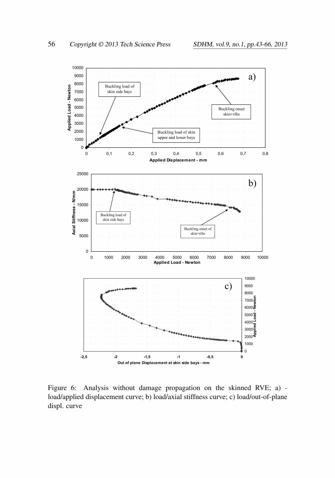
In Figure 6(a) the load-displacement curve is presented. This figure does not clearlyshow the buckling onset of the structure; hence, the axial stiffness as function of theload has been plotted in Figure 6(b). At 1427 N, a first drop down in the axial stiff-ness of the structure can be pointed out. Such decrease is representative of the localbuckling of the skin side bays. A second drop down in the axial stiffness, occurringat about 8167 N, can be associated to the buckling of the ribs (global buckling).From the analysis of figures 6(a) and 6(b) the buckling load of the skin (local buck-ling) starts for an applied displacement of about 0.07mm while the buckling loadof the ribs (global buckling) initiates for an applied displacement of 0.57mm. InFigure 6(c) the out-of-plane displacement curve as function of the applied load isshown. The out-of-plane displacements have been evaluated at (x,y) = (0, h/2) and(x,y) = (b, h/2). Since a perfect overlap in the out-of-plane displacements at themonitored positions has been found, only one curve has been reported in the Fig-ure 6(c). the buckling on-set of the skin side bay (local buckling) and the bucklingon-set in the ribs (global buckling) can be easily appreciated.

Intra-laminar Damage Evolution 55
Local buckling
Load: 1427 N
Uy: -0.072 mm
Load: 6697 N
Uy: -0.432 mm
Global buckling
Load: 8167 N
Uy: -0.572 mm
Load: 8660 N
Uy: -0.678 mm
Figure 5: Analysis without damage propagation on the skinned RVE – deformedshapes at different load steps
4.2.2 Analysis with damage propagation on the Skinned RVE
The compression behavior of the skinned RVE shown in the previous subsection isnot realistic since the damage in matrix and fibers, expected to occur as a conse-
56 Copyright © 2013 Tech Science Press SDHM, vol.9, no.1, pp.43-66, 2013
0
1000
2000
3000
4000
5000
6000
7000
8000
9000
10000
0 0,1 0,2 0,3 0,4 0,5 0,6 0,7 0,8Applied Displacement - mm
App
lied
Load
- N
ewto
n
Buckling onset skin+ribs
Buckling load of skin upper and lower bays
Buckling load of skin side bays
0
5000
10000
15000
20000
25000
0 1000 2000 3000 4000 5000 6000 7000 8000 9000 10000Applied Load - Newton
Axia
l Stif
fnes
s - N
/mm
Buckling load of skin side bays
Buckling onset of skin+ribs
0
1000
2000
3000
4000
5000
6000
7000
8000
9000
10000
-2,5 -2 -1,5 -1 -0,5 0Out of plane Displacement at skin side bays - mm
Appl
ied
Load
- Ne
wto
n
a)
b)
c)
Figure 6: Analysis without damage propagation on the skinned RVE; a) -load/applied displacement curve; b) load/axial stiffness curve; c) load/out-of-planedispl. curve

Intra-laminar Damage Evolution 57
quence of the skin buckling, has not been taken into account. In order to investigatethe mechanical behavior of grid structures when damage onset and propagation oc-cur, a geometrically non-linear analysis with an applied displacement of 1mm in they-direction has been performed by adopting the implemented progressive damageapproach described in section 3.
The results of the non-linear static analysis with damage propagation in terms offibers and matrix breakage are shown in figures 7 and 8.
In Figure 7 the deformed shapes of the non-linear static analysis with damage prop-agation at different load steps are reported for both 80˚ and –80˚ oriented plies. Inorder to show the B2000 outputs in terms of damage growth, the integer values ofTable 1 have been used to represent the failure mode in the ply.
According to Figure 7 no damage has been detected up to the local buckling. Thedamage on-set, consisting of both matrix and fiber breakage, has been found for anapplied load of 4263 N. The damage propagates as fiber and shear out failure thataffects only the skin but has an impact on the whole structure load carrying capa-bility. Indeed, by increasing the displacement in the y-direction, the skin suddenlyreaches the collapse for an applied displacement of 2,757mm (load of 4169 N).
In practice, the collapse load obtained by this procedure takes into account thedamage onset and propagation in the skin and shows that the skin is of main con-cern for the integrity of the whole grid structure. This global failure is reachedapproximately at the 50% of the global buckling load found without consideringthe failure. This is a proof of the relevance of the failure onset and propagationwhen simulating the mechanical behavior of composite grid structures. Figure 8(a)(load-displacement curve) and Figure 8(b) (axial stiffness as a function of the load)show that the local buckling of the skin, as for the analysis with damage propaga-tion, occurs at about 1427 N. The damage onset is not visible in this figures while asudden drop in the load carrying capability and in the axial stiffness show the finalfailure of the RVE.
In Figure 8(c) the out-of-plane displacement curves as function of the applied loadis reported. The out-of-plane displacement is evaluated at (x,y) = (0, h/2) and (x,y)= (b, h/2).
No appreciable difference can be observed with respect to the no-damage approachin terms of out of plane displacements and local buckling value.
4.2.3 Analysis with damage propagation on the RVE without skin
Sometimes, the grid structures are manufactured with very thin skins which, dif-ferently from the previously analyzed configurations, does not contribute signifi-cantly to the global load carrying capability, hence the global failure is driven by

58 Copyright © 2013 Tech Science Press SDHM, vol.9, no.1, pp.43-66, 2013
Load: 4263 N
Uy: -0.2518 mm
Load: 4169 N
Uy: -0.2757 mm
Load: 4427 N
Uy: -0.2646 mm
-80° 80°
Figure 7: Analysis with damage propagation on the skinned RVE – deformedshapes with failure modes contours at different load steps

Intra-laminar Damage Evolution 59
0
500
1000
1500
2000
2500
3000
3500
4000
4500
5000
0 0,05 0,1 0,15 0,2 0,25 0,3Applied Displacement - mm
Appl
ied
Load
- Ne
wto
n
Local buckling
Damage onset
Final failure
0
5000
10000
15000
20000
25000
0 500 1000 1500 2000 2500 3000 3500 4000 4500 5000Applied Load - Newton
Axi
al S
tiffn
ess
- N/m
m
Local buckling
Damage onset Final failure
0
500
1000
1500
2000
2500
3000
3500
4000
4500
5000
-1,8 -1,6 -1,4 -1,2 -1 -0,8 -0,6 -0,4 -0,2 0
Out of plane Displacement on the skin side bays - mm
Appl
ied
Load
- N
ewto
n
Buckling load side bay skin
a)
b)
c)
Figure 8: Analysis with damage propagation on the skinned RVE: a) - load/applieddisplacement curve; b) load/axial stiffness curve; c)load/out-of-plane displacementcurve

60 Copyright © 2013 Tech Science Press SDHM, vol.9, no.1, pp.43-66, 2013
Load: 4170 N
Uy=-0.49 mm
Load: 4167 N
Uy=-1.01 mm
Load: 3903 N
Uy=-1.08 mm
Load: 3585 N
Uy=-1.35 mm
Figure 9: Analysis with damage propagation on the RVE without skin – deformedshapes with failure modes contours at different load steps

Intra-laminar Damage Evolution 61
the damage in the ribs. In this subsection, in order to investigate the damage onsetand evolution in the ribs of composite grid structures, an application of the pro-posed progressive damage approach to an RVE without skin is presented. The RVEshown in Figure 3 without the skin has been loaded in compression by applying adisplacement of 3mm in the y direction. A geometrically non-linear analysis hasbeen performed by taking into account the damage onset and progression in termsof fiber breakage and matrix cracking. In figure 9 the deformed shapes at differ-ent time steps are presented. The damage propagation contours (plotted accordingto the values of Table 1) provide a description of the damage evolution during theloading process. Fiber, matrix and shear-out failure initiates in the back of the inter-section between two diagonal ribs after the buckling occurring at 4170 N. Quicklythe damage propagates along the thickness and fiber failure becomes visible. Whencomplete failure of the structure is detected, the load carrying capability is reduced(load at failure of 3585 N) and about the 80% of the plies in the intersection be-tween the diagonal ribs are completely broken.
In figure 10(a) the load-displacement curve is shown. The buckling onset at 4170N is visible together with the decrease in load carrying capability before failure.In figure 10(b) the axial stiffness as a function of the load is presented. Onceagain the reduction in stiffness associated with the buckling phenomenon can beappreciated. Finally, figure 10(c) shows the load-out-of-plane displacement curveat the intersection between the two diagonal ribs. The global buckling and the lossof load carrying capability is clearly pointed out.
5 Conclusions
In this paper the damage on-set and propagation in terms of fiber and matrix break-age on a composite grid structure Representative Volume Element have been in-vestigated. A progressive damage model implemented in the Finite Element codeB2000 has been used for computations. Geometrically non-linear structural anal-yses both in presence of damage and not have been carried out on the compositeRVE with skin and without skin, in order to understand the influence of damageonset and propagation respectively in skin and ribs on the compression behavior ofcomposite grid structures. The results for the skinned RVE show that no apprecia-ble differences have been found between the damage and the no-damage approachup to the local buckling of the skin, while the fiber and matrix breakage consid-erably affect the post buckling behavior. The damage on-set in terms of matrixcracking takes place very soon during the loading process and the propagation ofdamage in terms of shear-out and ply complete failure lead to a premature collapseof the skin and consequently of the complete skinned RVE. The results obtainedfor the grid without skin (lattice structure) show matrix cracking on-set occurring

62 Copyright © 2013 Tech Science Press SDHM, vol.9, no.1, pp.43-66, 2013
0
500
1000
1500
2000
2500
3000
3500
4000
4500
0 0,2 0,4 0,6 0,8 1 1,2 1,4
-New
ton-
-mm-
Non-linear Analysis with progressive damage (Lattice Structure)
First ply failure load
Buckling load
Buckling
0
1000
2000
3000
4000
5000
6000
7000
8000
9000
10000
0,00 500,00 1000,00 1500,00 2000,00 2500,00 3000,00 3500,00 4000,00 4500,00
-N/m
m-
-Newton-
Axial Stiffness with progressive damage (lattice structure)
Buckling onset
First ply failure load
Buckling load
0
500
1000
1500
2000
2500
3000
3500
4000
4500
0 1 2 3 4 5 6 7
-New
ton-
-mm-
Out-of-plane displacement curve with progressive damage (lattice structure)
a)
b)
c)
Figure 10: Analysis with damage propagation on RVE without skin: a) load/applieddisplacement curve; b) load/axial stiffness curve; c)load/out-of-plane displacementcurve

Intra-laminar Damage Evolution 63
after the rib buckling load between the diagonal ribs. Then fiber breaking and plycomplete failure propagate all along the thickness causing the diagonal ribs failure.Indeed, the information on damage evolution in composite grid structure obtainedby applying the proposed progressive damage model, already applied and validatedagainst experimental results, to a simplified RVE subjected to simplified loadingand boundary conditions could provide a first insight on the failure mechanismsoccurring when dealing with this kind of structures. These first information will beuseful to start a more focused numerical and experimental test campaign finalizedto the investigation of failure mechanisms in composite grid structures. Howeverthe inclusion of more complex boundary conditions and of delaminations onsetand propagation in the proposed damage model, represents an interesting subjectfor future developments, aimed to a more detailed understanding of composite gridstructures failure mechanisms.
References
Armentani, E., Calì, C., Caputo, F., Cricrì, G., Esposito, R. (2006): Numericalsolution techniques for structural instability problems. Journal of Achievements inMaterials and Manufacturing Engineering, vol. 19-1, pp. 53-64.
Balhi, N., Vrellos, N.; Drinkwater, B.W.; Guild, F.J.; Ogin, S.L.; Smith, P.A.(2006) Intra-laminar cracking in CFRP laminates: observations and modellingSource: Journal of Materials Science,v 41, n 20, p 6599-609.
Berbinau, P., Soutis, C., Guz, I. A. (1999): Compressive failure of 0˚ unidirec-tional CFRP laminates by fibre microbuckling. Composites Sci. & Technol., vol.59(9), pp. 1451-1455.
Buragohain, M., Velmurugan, R. (2011): Study of filament wound grid-stiffenedcomposite cylindrical structures. Compos Struct, vol. 93, pp. 1031-1038.
Caputo, F., Esposito, R., Perugini, P., Santoro, D. (2002): Numerical-experimentalinvestigation on post-buckled stiffened composite panels. Composite Structures,vol. 55/3 pp. 347-357.
Caputo, F., Lamanna, G., Soprano, A. (2006): Numerical Investigation on theCrack Propagation in a Flat Stiffened Panel. Key Engineering Materials, vol. 324-325, pp. 559-562.
Christensen, R.M. (1988): Tensor Transformation and Failure Criteria for theAnalysis of Fibre Composite Materials. J. of Comp. Mat., vol. 22, pp. 874-897.
Feng, W.W. (1991): A Failure Criterion for Composite Materials. J. of Comp.Mat., vol. 25, pp. 88-100.
Forghani, A., Zobeiry, N.; Vaziri, R.; Poursartip, A.; Ellyin, F. (2009): A con-

64 Copyright © 2013 Tech Science Press SDHM, vol.9, no.1, pp.43-66, 2013
sistent framework for formulation and characterization of a sub-laminate baseddamage model. 17th International Conference on Composite Materials.ICCM-17.
Fu, Yimin, Li, Sheng; Jiang, Yejie (2008): Analysis of inter-laminar stresses forcomposite laminated plate with interfacial damage. Acta Mechanica Solida Sinica,v 21, n 2, p 127-140.
Gan, C., Gibson, RF., Newaz, G.M. (2004): Analytical/Experimental Investiga-tion on Energy Absorption in Grid-stiffened Composite Structures under Trans-verse Loading. Experimental Mechanics, vol. 44/2, pp. 185-194.
Hahn, H.T., Tsai, S.W. (1983): On the Behaviour of Composite Laminates AfterInitial Failures. Astronautics and Aeronautics, vol. 21, pp. 58-62.
Hashin, Z. (1980): Failure Criteria for Unidirectional Fiber Composites. ASMEJournal of Applied Mechanics, vol. 47, pp. 329-334.
Hashin, Z., Rotem, A. (1973): A Fatigue Failure Criterion for Fibre ReinforcedMaterials. Journal of Composite Materials, vol. 7, pp. 448-474.
He, J.-X., He, G.-Q. (2010): Strength analysis of composite grid stiffened struc-ture. Guti Huojian Jishu/Journal of Solid Rocket Technology, vol. 33/4, pp. 449-458.
Hou, A., Gramoll, K. (2000): Fabrication and compressive strength of the com-posite attachment fitting for launch vehicle. J Adv Mater, vol. 32/1, pp. 39-45.
Huybrechts, S.M., Meink, T.E., Wegner, P.M., Ganley, J.M. (2002): Manufac-turing theory for advanced grid stiffened structures. Comp Part A: Applied Scienceand Manufacturing, vol. 33/2, pp. 155-161.
Kashtalyan, M., Soutis, C. (2005): Analysis of composite laminates with intra-and interlaminar damage. Progress in Aerospace Science, vol. 41, pp. 152-173.
Katerelos, D.T.G., Kashtalyan, M., Soutis, C., Galiotis, C. (2008): Matrix crack-ing in polymeric composites laminates: Modelling and experiments. CompositesScience and Technology, vol. 68, pp. 2310-2317.
Kidane, S., Helms, GLiJ., Pang, S., Woldesenbet, E. (2003): Buckling load anal-ysis of grid stiffened composite cylinders. Comp: Part B, vol. 34, pp. 1-9.
Li, L.Y. , Wen, P.H.; Aliabadi, M.H (2011): Meshfree modeling and homogeniza-tion of 3D orthogonal woven composites. Composites Science and Technology, v71, n 15, p 1777-1788, 24.
Merazzi, S., de Boer, A. (1994): B2000 Manuals. SMR Corp.
Murray, Y., Schwer, L. (1990): Implementation and Verification of Fiber Compos-ite Damage Models, Failure Criteria and Analysis in Dynamic Response. ASMEAMD, vol. 107, pp. 21-30.

Intra-laminar Damage Evolution 65
Nahas, M.N. (1986): Survey of Failure and Post-Failure Theories of LaminatedFibre Reinforced Composites. Journal of Composites Technology and Research,vol. 8, pp. 138-153.
Ochoa, O.O., Reddy. J.N. (1992): Finite Element Analysis of Composite Lami-nates. Kluwer Academic Publishers, Dordrecht, The Netherlands.
Petit, P.H., Waddoups, M.E. (1969): A Method of Predicting the Non-LinearBehaviour of Laminated Composites. J. of Comp. Mat., vol. 3, pp. 2-19.
Pietropaoli, E., Riccio, A. (2011): A Global/Local Finite Element Approach forPredicting Interlaminar and Intralaminar Damage Evolution in Composite StiffenedPanels Under Compressive Load. Applied Composite Materials, vol. 18/2, pp. 113-125.
Raimondo, L., Aliabadi, M.H. (2009): Multiscale progressive failure analysis ofplain-woven composite materials, Journal of Multiscale Modeling, v 1, n 2, p 263-301.
Riccio, A., Marciano, L. (2005) Effects of Geometrical and Material Featureson Damage Onset and Propagation in Single-lap Bolted Composite Joints underTensile Load: Part I – Experimental Studies. Int. Journal of Composite Materials,vol. 39/23, pp. 2071-2090.
Riccio, A. (2005): Effects of Geometrical and Material Features on Damage Onsetand Propagation in Single-lap Bolted Composite Joints under Tensile Load: Part II– Numerical Studies. Int. Journal of Composite Materials, vol. 39/23, pp. 2091-2112.
Riccio, A., Pietropaoli, E. (2008): Modelling damage propagation in compositeplates with embedded delamination under compressive load. Int. Journal of Com-posite Materials, vol. 42/13, pp. 1309-1335.
Riks, E. (1984): Progress in collapse analysis. ASME Pressure Vessel and PipingConference (session on Collapse Analysis of Structures – I), San Antonio, Texas.
Sandhu, R.S. (1974): Non-Linear Behaviour of Unidirectional and Angle PlyLaminates. AIAA Journal of Aircraft, vol. 13, pp. 104-111.
Sleight, D.W., Knight. N.F., Wang, J.T. (1997): Evaluation of a Progressive Fail-ure Analysis Methodology for Laminated Composite Structures. AIAA Paper, 97-1187, AIAA/ASME/ASCE/AHS/ASC Structures, Structural Dynamics, and Mate-rials Conference and Exhibit.
Sleight, D.W. (1999): Progressive Failure Analysis Methodology for LaminatedComposite Structures. NASA/TP-1999-209107.
Soutis, C., Kashtalyan, M. (2011): Residual Stiffness of Cracked Cross-Ply Com-posite Laminates Under Multi-Axial In-plane Loading. Applied Composite Mate-

66 Copyright © 2013 Tech Science Press SDHM, vol.9, no.1, pp.43-66, 2013
rials, vol. 18, pp. 31-43.
Stellbrink Kuno, K.U. (1996): Micromechanics of Composites. Carl Hanser Ver-lag, New York.
Tessitore, N., Riccio, A. (2005) Development and application of a progressivedamage approach to a grid structure representative volume element. Proceedingsof the 10th International Conference on Civil, Structural and Environmental Engi-neering Computing, Civil-Comp.
Tsai, S.W., Wu, E.M. (1971): A General Theory of Strength for Anisotropic Ma-terial. J. of Comp. Mat., vol. 5, pp. 58-80.
Vasiliev, V.V., Barynin, V.A., Rasin, A.F. (2001): Introduction to the design andbehavior of bolted joints. Compos Struct, vol. 54, pp. 361-370.
Vasiliev, V.V., Razin, A.F. (2006): Anisogrid composite lattice structures for space-craft and aircraft applications. Compos Struct, vol. 76, pp. 182-189.
Wodesenbet, E., Kidane, S., Pang, S. (2003): Optimization for buckling loads ofgrid stiffened composite panels. Compos Struct, vol. 60, pp. 159-169.
Yamada, S.E., Sun, C.T. (1978): Analysis of Laminate Strength and its Distribu-tion. J. of Comp. Mat., vol. 12, pp. 275-284.
Zhang, Z., Chen, H., Ye, L. (2008): Progressive failure analysis for advanced gridstiffened composite plates/shells. Comp Struct, vol. 86, pp. 45-54.