interworking between wireless local area networks and 3g
TRANSCRIPT

CHAPTER 22
Interworking between Wireless Local Area Networks and
3G Wireless Wide Area Networks
22.1 IntroductionWireless local area networks (WLANs) are subjected to interference because of their operation in the unlicensed spectrum. WLANs’ coverage ranges from about 30 to 300 m. Therefore, they are suitable only in high-density areas and thus not able to provide ubiquitous coverage. WLAN technology is relatively inexpensive and quick to deploy. Although WLANs were originally designed to extend LANs in corporate environments, they are becoming increasingly popular to provide IP connectivity in residential, small offi ce home offi ce (SOHO), and campus environ-ments. A new phenomenon in populated areas has emerged to deploy WLANs in public hotspots including airports, coffee houses, convention centers, hotels, and other public areas with a high demand for wireless data.
Both WLANs and 3G are capable of providing higher-speed wireless connections that cannot be offered by earlier 2G cellular technologies. Therefore, they seem to compete. However, each technology has niche market applications. WLANs can cover only a small area and allow limited mobility, but provide higher data rates. Therefore, WLANs are well suited to hotspot coverage where there is a high density of demand for high-data-rate wireless services requiring limited mobil-ity. On the other hand, 3G wireless networks, with their well-established voice support, wide coverage, and high mobility, are more suited to areas with moder-ate or low-density demand for wireless usage requiring high mobility. Therefore, WLANs and 3G are complementary. The integration of 3G wireless and WLANs is highly signifi cant to make wireless multimedia and other high-data-rate services a reality for a large population. A multimedia 3G/WLAN terminal can access high-bandwidth data services where WLAN coverage is offered, while accessing wide area networks using 3G at other places. However, this approach alone will only allow limited multi-access functionality. To make multi-access solutions effective, we need an integrated solution to provide seamless mobility between access tech-nologies, allowing continuity of existing sessions. 3G/WLAN integration promises to offer these capabilities seamlessly [1,2,11–13].
22-1
Ch22-P373580.indd 22-1Ch22-P373580.indd 22-1 5/4/07 1:25:34 AM5/4/07 1:25:34 AM
In the standard arena, work is going on both in the 3G partnership project (3GPP) and 3GPP2 on 3G/WLAN integration. 3GPP has specifi ed an interwork-ing architecture that enables users to access their 2G and 3G data services from WLANs. 3GPP2 has been initiated to examine the issues of 3G/WLAN interwork-ing. They are fi nalizing stage 1 specifi cations of the interworking system and in the near future will start the architectural activities.
Several WLAN standardization organizations (in particular ETSI BRAN, IEEE 802.11, IEEE 802.15 and multimedia access communication (MMAC)) have agreed to set up a joint wireless interworking group (WIG) to deal with the interworking between WLANs and cellular networks. This activity is being driven primarily from Europe by ETSI BRAN.
In this chapter we focus on interworking issues of WLANs and wireless wide-area networks (WWANs). We also discuss the local multipoint distribution system (LMDS) and the multichannel multipoint distribution system (MMDS).
22.2 Interworking Objectives and RequirementsOne of the principal objectives of interworking is to allow independent evolution of 3GPP (WWAN) and WLAN standards. The extent of interdependence between these standards should be minimized or localized at the point of interconnection.
Support for the legacy WLAN user is perhaps the most important objec-tive of a 3GPP-WLAN interworking setup. A legacy WLAN user is a user with a WLAN-capable device and a subscription to 3GPP services. The user may or may not be 3GPP capable. Such a user should be able to access 3GPP services without substantial hardware/software upgrades. Such a setup would result in a strong business case, leading to extend the facility of 3GPP services to the user who, although having a 3GPP subscription, does not want to spend it on additional hardware/software upgrades. The other objective of interworking is the single subscription.
The following are the interworking requirements:
Common billing and customer care. This is the simplest form of interworking that provides a common bill and customer care to the subscriber but oth-erwise requires no real interworking between the WLAN and 3GPP data networks.
3GPP-based access control and charging. This requires authentication, authorization, and accounting (AAA) for subscribers in the WLAN to be based on the same AAA procedures used in the 3GPP data networks. It means a mobile subscriber can use his or her subscriber identity module/ UMTS-SIM (SIM/USIM) to access WLAN services.
Access to 3GPP-based packet switched services. The aim of this requirement is to allow the mobile operator to allow access to its 3GPP data services to
•
•
•
22-2 22 Interworking between Local Area Networks and 3G Wide Area Networks
Ch22-P373580.indd 22-2Ch22-P373580.indd 22-2 5/4/07 1:25:36 AM5/4/07 1:25:36 AM

subscribers in a WLAN environment. It means a mobile subscriber should be able to access/select 3GPP data services through the WLAN access network. Although the user is allowed access to the same 3GPP data services over both the 3GPP and WLAN access networks, no service continuity across these access networks is required in this scenario.
Service continuity. The goal is to allow seamless service continuity across the 3GPP and WLAN systems. It means that a user session during mobility across these networks should not only continue but also should not have noticeable service change in terms of quality and disruption.
Access to 3GPP circuit-switched services. The goal of this requirement is to allow the 3GPP operator to offer access to circuit-switched services such as voice calls from the WLAN systems. Seamless service continuity is a must for these services.
22.3 Interworking Schemes to Connect WLANs and 3G Networks
Based on the objectives and requirements discussed in the previous section, we present interworking schemes to connect WLANs and 3GPP networks [5–10].
Basically, interworking schemes can be categorized as mobile IP approach, gateway approach, and emulator approach. Mobile IP approach (called loose cou-pling approach), introduces mobile IP to two networks. Mobile IP mechanisms can be implemented in the mobile nodes and installed on the network devices of 3G and WLANs. This approach provides IP mobility for roaming between 3G and WLANs. However, this approach requires installing mobile IP devices such as a home agent (HA) and a foreign agent (FA) in both networks, and terminal devices should also implement mobile IP features. Since the user device requires sending the registration back to its home network, packet delay and loss are also a problem for handoffs. Moreover, this approach suffers from the triangular routing between networks if mobile IP does not support route optimization (see Figure 22.1).
The gateway approach introduces a new logical node to connect two wireless networks. The new node is located between the two networks and acts as an internal device. It exchanges necessary information between the two networks, converts signals, and forwards the packets for the roaming users. This approach aims to separate the operations of two networks, which implies the two networks are peer-to-peer networks and can handle their subscriber independently. With the two network operators having a roaming agreement, the logical node helps two networks offer intersystem roaming. The advantages of this approach are that the two networks can be operated independently; packets for roaming users go through the node without processing by mobile IP; and handoff delay and loss can be reduced (see Figure 22.2).
•
•
22.3 Interworking Schemes to Connect WLANs and 3G Networks 22-3
Ch22-P373580.indd 22-3Ch22-P373580.indd 22-3 5/4/07 1:25:36 AM5/4/07 1:25:36 AM

The emulator approach (called tight coupling approach), uses WLAN as an access stratum in a 3G network. This approach replaces 3G access stratum by WLAN layer one and layer two. A WLAN access point (AP) can be viewed as a 3G network controller or a serving GPRS support node (SGSN). The benefi t of this approach is that mobile IP is not required. All packet routing and forward-ing are processed by a 3GPP core network. The packet loss and delay can be reduced signifi cantly. However, this approach lacks fl exibility since two networks
22-4 22 Interworking between Local Area Networks and 3G Wide Area Networks
Figure 22.1 Architecture of the mobile IP approach.
RNC 3G-SGSN 3G-GGSN
WLAN APL1, L2
Host
FA/HA
UE
UE: User EquipmentAP: Access PointRNC: Radio Network Controller3G-SGSN: 3G Serving GPRS Support Node3G-GGSN: 3G Gateway GPRS Support NodeFA: Foreign AgentHA: Home Agent
IP Router
Figure 22.2 Architecture of the gateway approach.
RNC 3G-SGSN 3G-GGSN
WLAN APL1, L2
IP Router
Host
UE
UE: User EquipmentAP: Access Point3G-SGSN :3G Serving GPRS Support Node3G-GGSN :3G Gateway GPRS Support NodeRNC: Radio Network Controller
RouterGateway
Ch22-P373580.indd 22-4Ch22-P373580.indd 22-4 5/4/07 1:25:37 AM5/4/07 1:25:37 AM

are tightly coupled. The operators of two networks should be the same in order to exchange much information. Another disadvantage of this approach is that the gateway GPRS support node (GGSN) will be the single point to the Internet. All packets have to go through the GGSN fi rst. GGSN and the core network become the bottleneck (see Figure 22.3).
22.4 De Facto WLAN System Architecture3GPP WLAN interworking architecture design work is focused on the interworking functionality between 3GPP and WLAN systems. To achieve a 3GPP-WLAN interworking architecture that is widely adopted, it is imperative to use the exist-ing de facto WLAN access equipment. Unlike the 3GPP system architecture, there is no existing formal standard for a WLAN access network architecture or for a typical public access WLAN system. The WLAN system shown in Figure 22.4 enables IP connectivity between the WLAN terminal and IP networks over its WLAN interface. A dynamic host confi guration protocol (DHCP) server is needed to facilitate confi guration of the WLAN terminal’s IP stack. A domain name server (DNS) resolves Internet fully qualifi ed domain name (FQDN) addresses into IP addresses. A Gateway (GW)/network address and port translation (NAPT) is a gateway toward external IP networks such as the Internet. The GW usually also performs IP network address and port translations to enable the WLAN access network operator to use private-space IP addresses inside the WLAN system and enable access to services available outside IP networks at the same time.
An hyper text transfer protocol (HTTP) server may offer local application-level service for accessing users. Accounting data is processed in the billing system server. The local services server is a general box covering services at IP level or
22.4 De Facto WLAN System Architecture 22-5
Figure 22.3 Architecture of the emulator approach.
RNC 3G-SGSN 3G-GGSN
WLAN APL1, L2
Host
UE
UE: User EquipmentAP: Access PointRNC: Radio Network Controller3G-SGSN: 3G Serving GPRS Support Node3G-GGSN: 3G Gateway GPRS Support Node
RNCEmulator
Router
Ch22-P373580.indd 22-5Ch22-P373580.indd 22-5 5/4/07 1:25:38 AM5/4/07 1:25:38 AM

Fig
ure
22
.4
A d
e fa
cto
WLA
N s
yste
m.
IPB
ackb
one
Net
wor
k
Acc
ess
Rou
ter
Loca
lS
ervi
ces
Use
rD
B
Acc
ess
Rou
ter
Net
wor
kM
anag
emen
tD
NS
DH
CP
AA
AS
erve
r/pr
oxy
Bill
ing
Sys
tem
HT
TP
Ser
ver
Gat
eway
NA
PT
L2D
istr
ibut
ion
Net
wor
k
WLA
NA
P
WA
NTe
rmin
al
WLA
NA
P
Oth
er W
LAN
AP
s
WA
NTe
rmin
al
L2 D
istr
ibut
ion
Net
wor
k
WLA
N R
adio
Inte
rfac
e
Inte
rfac
e to
Ext
erna
lIP
Net
wor
ks (
Inte
rnet
)
IPIn
terf
ace
AA
AR
oam
ing
DH
CP
: Dyn
amic
Hos
t Con
figur
atio
n P
roto
col
AA
A: A
uthe
ntic
atio
n, A
utho
rizat
ion,
and
Acc
ount
ing
DB
: Dat
a B
ase
NA
PT
: Net
wor
k A
ddre
ss a
nd P
ort T
rans
latio
nD
NS
: Dom
ain
Nam
e S
erve
r
22-6 22 Interworking between Local Area Networks and 3G Wide Area Networks
Ch22-P373580.indd 22-6Ch22-P373580.indd 22-6 5/4/07 1:25:39 AM5/4/07 1:25:39 AM

above, such as mail servers and local web content. Network management takes care of the management of all network elements at all layers. It is instrumental in network confi guration and monitoring.
The WLAN terminal is typically a laptop computer or a personal digital assistant (PDA) with a built-in WLAN module or a PCMCIA WLAN card. The WLAN AP is mostly a layer 2 bridge between IEEE 802.11 and the Ethernet. The AP can also support IEEE 802.11i/802.1X functionality, in which case it is also a remote authentication dial-in user service (RADIUS) client toward the fi xed network and performs radio link encryption toward the WLAN terminal. Access points are attached to layer 2 distribution networks such as a switched Ethernet subnet. The layer 2 distribution network may also provide intra-subnet mobility for WLAN terminals. The layer 2 distribution network enables layer 2 connectiv-ity toward the fi rst IP routing device, the access router (AR). The basic function of AR is to route user IP packets.
Authentication and authorization is one basic prerequisite for providing IP connectivity and other services via a WLAN system. To realize these functions, an authentication, authorization, and accounting (AAA) server and user database are required. An AAA server is typically the RADIUS server used for a WLAN system. The subscribers’ user identities such as login names, shared secrets like passwords, and user profi les are stored in the database. The database is accessed from the AAA server over the IP backbone network using lightweight directory access protocol (LDAP) as the de facto standard.
Legacy authentication and authorization is performed using Web browsers. When the user initiates Web browser, its fi rst request is redirected into a WLAN system HTTP server and a landing Web page is displayed. The user is prompted to enter a login name and password. The password can be static, limited time, or even generated ad hoc (using, e.g., Security ID technology). Similarly, users can be prompted to enter their credit card number and pay for the connection without establishing a more lasting relationship with the WLAN system operator.
It is also possible to establish a roaming relationship between WLAN sys-tems. Roaming enables a user of a WLAN system to connect to another WLAN system. In this case, the AAA functions are still provided by the user’s own WLAN system, while actual WLAN access is provided by other WLAN systems.
22.5 Session MobilitySession mobility may be seen as an evolutionary step from roaming in the integrated environment. Session is defi ned as a fl ow of IP packets between the end-user and an external entity; for example, an FTP or HTTP session. We consider a mobile device capable of connecting to the data network through WLANs and 3GPP networks. This could be a laptop with an integrated WLAN-general packet radio service (GPRS) card, or PDA attached to a dual access card. The end-user is con-nected to the data network and is in a session fl ow through one access network,
22.5 Session Mobility 22-7
Ch22-P373580.indd 22-7Ch22-P373580.indd 22-7 5/4/07 1:25:39 AM5/4/07 1:25:39 AM
say, a WLAN. As the user moves out of the coverage area of the WLAN, the end device detects the failing WLAN coverage and seamlessly switches the fl ow to the 3GPP network. The end-to-end session remains unaffected. Typically no user intervention would be required to perform the switchover from WLAN to 3GPP. When the user moves back into the coverage of the WLAN system, the fl ow is handed back to the WLAN.
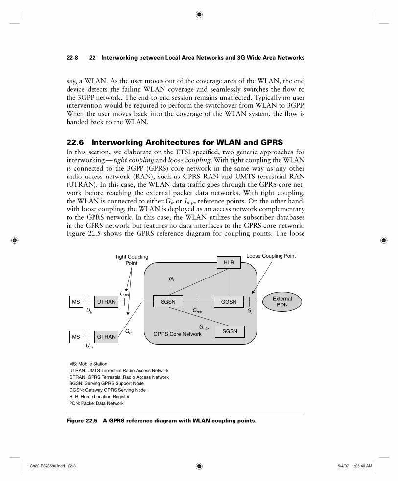
22.6 Interworking Architectures for WLAN and GPRSIn this section, we elaborate on the ETSI specifi ed, two generic approaches for interworking — tight coupling and loose coupling. With tight coupling the WLAN is connected to the 3GPP (GPRS) core network in the same way as any other radio access network (RAN), such as GPRS RAN and UMTS terrestrial RAN (UTRAN). In this case, the WLAN data traffi c goes through the GPRS core net-work before reaching the external packet data networks. With tight coupling, the WLAN is connected to either Gb or Iu-ps reference points. On the other hand, with loose coupling, the WLAN is deployed as an access network complementary to the GPRS network. In this case, the WLAN utilizes the subscriber databases in the GPRS network but features no data interfaces to the GPRS core network. Figure 22.5 shows the GPRS reference diagram for coupling points. The loose
22-8 22 Interworking between Local Area Networks and 3G Wide Area Networks
Figure 22.5 A GPRS reference diagram with WLAN coupling points.
SGSN GGSNMS UTRAN
HLR
SGSNMS GTRAN
ExternalPDN
Uu
Um
Iu-ps
Gb
Gr
Gi
Gn/p
Gn/p
GPRS Core Network
Loose Coupling Point Tight CouplingPoint
MS: Mobile StationUTRAN: UMTS Terrestrial Radio Access NetworkGTRAN: GPRS Terrestrial Radio Access NetworkSGSN: Serving GPRS Support NodeGGSN: Gateway GPRS Serving NodeHLR: Home Location RegisterPDN: Packet Data Network
Ch22-P373580.indd 22-8Ch22-P373580.indd 22-8 5/4/07 1:25:40 AM5/4/07 1:25:40 AM

coupling architecture between the GPRS and the WLAN at the Gi reference point is indicated. This means that with loose coupling, the WLAN bypasses the GPRS network and provides direct network data access to the external packet data networks (PDNs).
The trend is to follow the loose coupling approach and use SIM or USIM-based authentication and billing. With this approach, a subscriber can reuse the SIM card or the USIM card to access a set of wireless data services over a WLAN.
In the tight coupling approach, 3GPP system-based access control and charging is used. This requires AAA for subscribers in the WLAN to be based on the same AAA procedures used in the GPRS system. An access to 3GPP GPRS-based servi ces is used to allow the cellular operator to extend access to its GPRS-based services to subscribers in a WLAN environment. Also, seamless services scenarios provides seamless service continuity between GPRS and WLAN. The goal of 3GPP circuit-switched services is to allow the operator to offer access to circuit-switched services (e.g., normal voice calls) from a WLAN system. Seamless mobility for these services is provided. The advantages of tight coupling architecture between IEEE 802.11 WLANs and GPRS are the following:
Seamless service continuation across WLAN and GPRS. The users are able to maintain their data sessions as they move from WLAN to GPRS and vice versa. For services with tight coupling quality of service (QoS) require-ments, seamless service continuation is subject to WLAN QoS capabilities.
Reuse of GPRS AAA
Reuse of GPRS infrastructure (e.g., core network resources, subscriber data-bases, billing systems) and protection of cellular operator’s investment
Support of lawful interception for WLAN subscribers
Increased security, since GPRS authentication and ciphering can be used on top of WLAN ciphering
Common provisioning and customer care
Access to core GPRS services such as short message service (SMS), location-based services and multimedia messaging services (MMS)
22.7 System Description with Tight CouplingFigure 22.6 shows the system architecture with tight coupling. A WLAN is deployed with one or more off-the-shelf access points, which are connected by means of a distribution system. The distribution system is LAN-compliant with IEEE 802.3. The WLAN is deployed in an infrastructure confi guration, that is, APs behave like base stations, and mobiles exchange data only with APs. The service area of an AP is called a basic service set. Each WLAN is typically composed
•
•
•
•
•
•
•
22.7 System Description with Tight Coupling 22-9
Ch22-P373580.indd 22-9Ch22-P373580.indd 22-9 5/4/07 1:25:41 AM5/4/07 1:25:41 AM

Fig
ure
22
.6
WLA
N-G
PR
S i
nte
gra
tio
n w
ith
tig
ht
cou
pli
ng
sys
tem
co
nfi
gu
rati
on
.
Fea
ture
Ser
vers
GG
SN
CG
SG
SN
Fire
wal
l
Inte
rnet
Ope
rato
r’s IP
Net
wor
k
Bill
ing
Med
iato
r
Bill
ing
Sys
tem
UT
RA
N/
GT
RA
NG
PR
S C
ore
GIF
Dis
trib
utio
n S
yste
m
48-b
it80
2 M
AC
Add
ress
WL
AN
Net
wo
rk
)
AP
Gb
Dua
l Mod
eM
S
GIF
: GP
RS
Inte
rwor
king
Fun
ctio
n
CG
: Cha
rgin
g G
atew
ay
HLR
: Hom
e Lo
catio
n R
egis
ter
AuC
: Aut
hent
icat
ion
Cen
ter
SG
SN
: Ser
ving
GP
RS
Sup
port
Nod
e
GG
SN
: Gat
eway
GP
RS
Sup
port
Nod
e
BS
S: B
asic
Ser
vice
Set
AP
: Acc
ess
Poi
nt
S
802.
11 e
xten
ded
serv
ice
set (
ES
S)
Bea
con
(SS
ID)
BS
S-3
Bea
con
(SS
ID)
BS
S-1
Bea
con
(SS
ID)
BS
S-2
HLR
(AuC
)
22-10 22 Interworking between Local Area Networks and 3G Wide Area Networks
Ch22-P373580.indd 22-10Ch22-P373580.indd 22-10 5/4/07 1:25:42 AM5/4/07 1:25:42 AM

of many basic service sets, which all together form an extended service set (ESS) (see Chapter 21).
The WLAN network is deployed as an alternative RAN and connects to the GPRS core network through the standard Gb interface. From the core network point of view, the WLAN is considered as other GPRS routing areas (RAs) in the system. The GPRS core network does not identify the difference between an RA with WLAN radio technology and one with GPRS radio technology.
The key functional element in the system is the GPRS interworking function (GIF), which is connected to a distribution system and to an SGSN via the stan-dard Gb interface. The main function of the GIF is to provide a standardized interface to the GPRS core network and to virtually hide the WLAN particulari-ties. The GIF is the function that makes the SGSN consider the WLAN a typical routing area.
The existing GPRS protocols in mobile are fully reused. The LLC, subnet-work dependent convergence protocol (SNDCP), GPRS mobility management (GMM), and session management are used in both a standard GPRS cell and a WLAN area. Therefore, the WLAN merely provides a new radio transport for these protocols.
When a mobile station (MS) is outside the WLAN area, its WLAN interface is in passive scan mode, that is, it scans a specifi c frequency band and searches for a beacon signal. When a beacon is received the service set identifi er (SSID) is checked and compared against a pre-confi gured SSID. The SSID serves as a WLAN identifi er and can help mobiles attach to the correct WLAN. For example, an operator could use a unique SSID and request that its subscribers confi gure their mobiles to consider only this SSID valid.
When an MS detects a valid SSID, it performs the typical authentication and association procedures. It then enables its WLAN interface, and further signaling is carried over this interface.
Mobile stations are dual mode, that is, they support both GPRS and WLAN access in a seamless fashion. System mobility is achieved by means of the routing area update (RAU) procedure, which is the core mobility management procedure in GPRS. Typically, when a mobile enters a WLAN area, an RAU procedure takes place, and subsequent GPRS signaling and user data transmission are carried over the WLAN interface. Similarly, when the mobile exits a WLAN area, another RAU procedure takes place, and the GPRS interface is enabled and used to carry further data and signaling traffi c. From the core network point of view, handoff between WLAN and GPRS is considered handoff between two individual cells.
Mobile stations in the WLAN send uplink GPRS traffi c to the MAC address of GIF; similarly, downlink GPRS traffi c is sent from the GIF to the MAC addresses of mobile stations (see Figure 22.6). The MS has two radio subsystems, one for GPRS access and another for WLAN access (refer to Figure 22.7). The WLAN adaptation function (WAF) identifi es when the WLAN radio subsystem is enabled
22.7 System Description with Tight Coupling 22-11
Ch22-P373580.indd 22-11Ch22-P373580.indd 22-11 5/4/07 1:25:43 AM5/4/07 1:25:43 AM
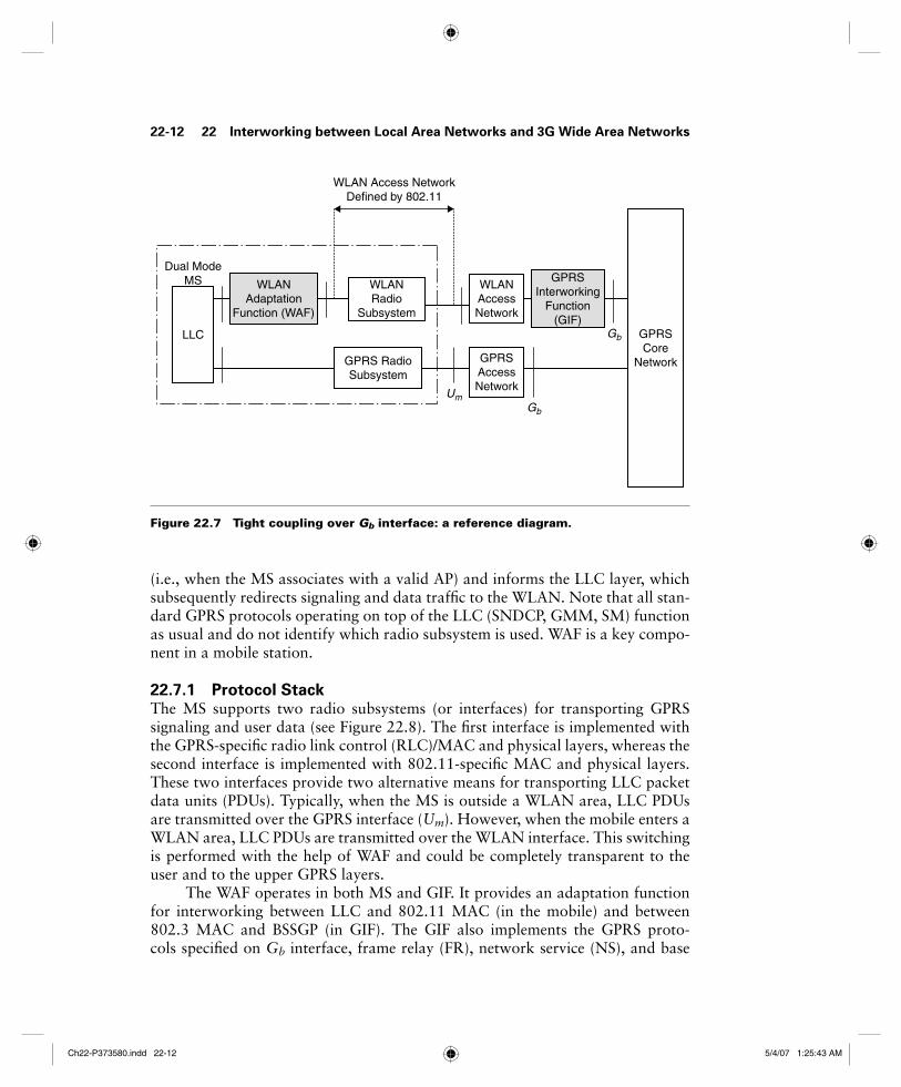
(i.e., when the MS associates with a valid AP) and informs the LLC layer, which subsequently redirects signaling and data traffi c to the WLAN. Note that all stan-dard GPRS protocols operating on top of the LLC (SNDCP, GMM, SM) function as usual and do not identify which radio subsystem is used. WAF is a key compo-nent in a mobile station.
22.7.1 Protocol StackThe MS supports two radio subsystems (or interfaces) for transporting GPRS signaling and user data (see Figure 22.8). The fi rst interface is implemented with the GPRS-specifi c radio link control (RLC)/MAC and physical layers, whereas the second interface is implemented with 802.11-specifi c MAC and physical layers. These two interfaces provide two alternative means for transporting LLC packet data units (PDUs). Typically, when the MS is outside a WLAN area, LLC PDUs are transmitted over the GPRS interface (Um). However, when the mobile enters a WLAN area, LLC PDUs are transmitted over the WLAN interface. This switching is performed with the help of WAF and could be completely transparent to the user and to the upper GPRS layers.
The WAF operates in both MS and GIF. It provides an adaptation function for interworking between LLC and 802.11 MAC (in the mobile) and between 802.3 MAC and BSSGP (in GIF). The GIF also implements the GPRS proto-cols specifi ed on Gb interface, frame relay (FR), network service (NS), and base
Figure 22.7 Tight coupling over Gb interface: a reference diagram.
GPRSCore
Network
LLC
WLANAdaptation
Function (WAF)
WLANRadio
Subsystem
GPRS RadioSubsystem
WLANAccessNetwork
GPRSAccessNetwork
GPRSInterworking
Function(GIF)
WLAN Access NetworkDefined by 802.11
Dual ModeMS
Gb
Gb
Um
22-12 22 Interworking between Local Area Networks and 3G Wide Area Networks
Ch22-P373580.indd 22-12Ch22-P373580.indd 22-12 5/4/07 1:25:43 AM5/4/07 1:25:43 AM

station subsystem GPRS protocol (BSSGP). The AP implements the 802.11 and 802.3 protocols and a simple interworking function that provides bridging between them.
22.7.2 WLAN Adaptation FunctionThe WAF is implemented in every dual mode MS and in the GIF. It supports the appropriate interworking functions. With the aid of WAF it becomes feasible to transport GPRS signaling and data over 802.11 WLANs. The WAF provides the following functions:
It signals the activation of the WLAN interface when a mobile enters a WLAN area. It also signals the change of RA to GMM when a mobile enters a WLAN area and gets associated with an AP.
It supports the GIF/RAI discovery procedure, which is initiated by MSs in order to discover the MAC address of GIF and the RA identity (RAI) of the WLAN.
•
•
22.7 System Description with Tight Coupling 22-13
Figure 22.8 Protocol stack for tight coupling over Gb interface.
GMM/SM SNDCP
Logical Link Control (LLC)
WAF WLAN Adaptation Function (WAF)
Dual-mode MS Access Point GPRS InterworkingFunction (GIF)
User Data
SGSN
802.11 MAC
802.11X PHY
RLC/MAC
GPRS PHY
Gb
802.11 MAC
802.11X PHY
802.3 MAC 802.3 MAC
100Base-Tor other
100Base-Tor other
BSSGP
NS
Frame Relay
PHY(e.g. G703/704)
Um
Ch22-P373580.indd 22-13Ch22-P373580.indd 22-13 5/4/07 1:25:44 AM5/4/07 1:25:44 AM
22-14 22 Interworking between Local Area Networks and 3G Wide Area Networks
It supports the paging procedure on Gb, used when SGSN needs to page an MS. During this procedure, WAF sends an appropriate signaling message to MS in order to alert it and respond to page.
It transfers uplink LLC PDUs from MS to the GIF by using the transport services provided by the 802.11 MAC. It also transfers downlink LLC PDUs from the GIF and in the MS.
It supports QoS by implementing transmission scheduling in the GIF and in the MS.
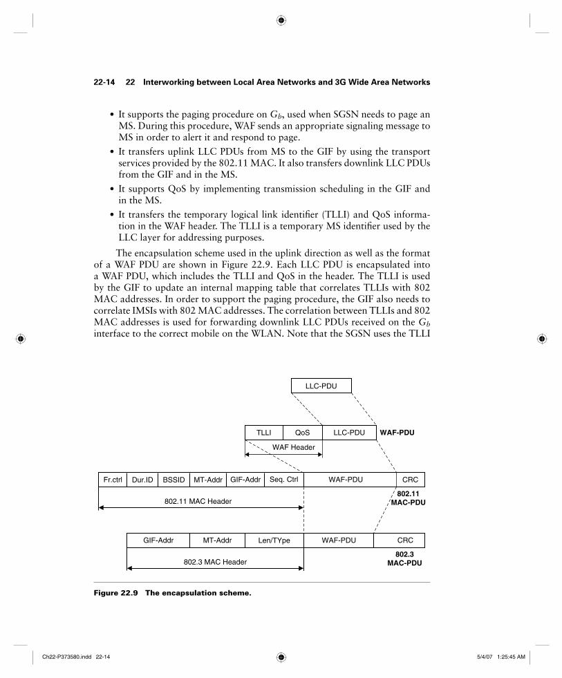
It transfers the temporary logical link identifi er (TLLI) and QoS informa-tion in the WAF header. The TLLI is a temporary MS identifi er used by the LLC layer for addressing purposes.
The encapsulation scheme used in the uplink direction as well as the format of a WAF PDU are shown in Figure 22.9. Each LLC PDU is encapsulated into a WAF PDU, which includes the TLLI and QoS in the header. The TLLI is used by the GIF to update an internal mapping table that correlates TLLIs with 802 MAC addresses. In order to support the paging procedure, the GIF also needs to correlate IMSIs with 802 MAC addresses. The correlation between TLLIs and 802 MAC addresses is used for forwarding downlink LLC PDUs received on the Gb interface to the correct mobile on the WLAN. Note that the SGSN uses the TLLI
•
•
•
•
Figure 22.9 The encapsulation scheme.
LLC-PDU
LLC-PDUQoSTLLI
CRCWAF-PDUFr.ctrl Dur.ID BSSID MT-Addr
WAF-PDU
Seq. Ctrl
WAF-PDU CRCGIF-Addr MT-Addr Len/TYpe
802.11 MAC Header
802.3 MAC Header
WAF Header
802.11MAC-PDU
802.3MAC-PDU
GIF-Addr
Ch22-P373580.indd 22-14Ch22-P373580.indd 22-14 5/4/07 1:25:45 AM5/4/07 1:25:45 AM

on Gb as address information, whereas the WLAN uses 802 MAC addresses. In the uplink direction, QoS contains the following attributes:
Peak throughput
Radio priority
RLC mode
These QoS attributes are primarily used for scheduling in the MS and GIF. In the downlink direction, the QoS may be empty, since there is no need to transfer any QoS parameters to the mobile. The 802.11 and 802.3 MAC headers (see Figure 22.8) are the standard headers specifi ed by the 802.11 and 802.3 stan-dards, respectively.
22.7.3 GIF/RAI Discovery ProcedureGIF/RAI discovery is a key procedure carried out immediately after an MS enters an 802.11 WLAN area and gets associated with an AP. The WAF in the MS initi-ates this procedure:
To discover the 802 MAC address of GIF. All uplink LLC PDUs are subse-quently transmitted to this MAC address.
To discover the RAI that corresponds to the WLAN network.
To send the MS’s IMSI value to GIF. This value is subsequently used by the GIF to support the GPRS paging procedure. By knowing the IMSI of a par-ticular MS, GIF can forward subsequent paging messages from the SGSN.
Figure 22.10 shows the signaling fl ow during the GAF/RAI procedure. The procedure is initiated after the 802.11 MAC layer is enabled (i.e., after the mobile gets associated with a particular AP). The WAF layer in an MS sends a request to 802.11 MAC to transmit a PDU with a source address (SA) equal to MS’s MAC address and a destination address equal to broadcast. This PDU is a GIF/RAI dis-cover request message that includes the IMSI value of the MS. The 802.11 MAC layer transmits an 802.11 MAC PDU with the appropriate address information (designated Addr1, Addr2, Addr3). Note that this PDU is directed to the AP with identity BSSID. The AP broadcasts this message to the MS and is fi nally received by the GIF, which associates the IMSI with the MS’s 802.11 MAC address (desig-nated MS). Subsequently, the WAF in the GIF responds with a GIF/RAI discover response that includes the RAI of the WLAN. The MS receives this response, stores the GIF address and the RAI, and notifi es the GMM layer that the current GPRS RA has changed. In response, the GMM layer initiates the normal GPRS RAU procedure and notifi es the SGSN that the MS has changed RA. After that, normal GPRS data and signaling is performed over the WLAN.
It should be noted that, with the aid of WAF, MSs can seamlessly move between WLAN and GPRS radio access and use the normal GPRS procedures for mobility management.
•
•
•
•
•
•
22.7 System Description with Tight Coupling 22-15
Ch22-P373580.indd 22-15Ch22-P373580.indd 22-15 5/4/07 1:25:46 AM5/4/07 1:25:46 AM

Fig
ure
22
.10
S
ign
alin
g fl
ow
du
rin
g a
GIF
/RA
I d
isco
very
pro
ced
ure
.
WA
F
MS
802.
11M
AC
/PH
YA
PG
IF(W
IF)
Ena
bled
GIF
/RA
I Dis
cove
r R
eque
st (
IMS
I)
802.11 encryption
GIF
/RA
I Dis
cove
r R
espo
nse
(RA
I)
DA
= b
road
cast
, SA
= M
S
DA
= M
S, S
A =
GIF
Add
r1 =
BS
SID
Add
r2 =
MS
Add
r3 =
bro
adca
st
802.
11 M
AC
PD
U
Add
r1 =
MS
Add
r2 =
BS
SID
Add
r3 =
GIF
Sto
re IM
SI a
nd c
orre
late
it to
MS
’s M
AC
add
ress
DA
= b
road
cast
, SA
= M
S,
Type
= W
AF
DA
= M
S, S
A =
GIF
,Ty
pe =
WA
F
802.
11 M
AC
PD
U
802.
3 M
AC
PD
U
802.
3 M
AC
PD
U
22-16 22 Interworking between Local Area Networks and 3G Wide Area Networks22-16 22 Interworking between Local Area Networks and 3G Wide Area Networks
Ch22-P373580.indd 22-16Ch22-P373580.indd 22-16 5/4/07 1:25:46 AM5/4/07 1:25:46 AM

22.8 System Description with Loose Coupling 22-17
22.8 System Description with Loose CouplingFigure 22.11 shows the system architecture with loose coupling. The WLAN is coupled with the GPRS network in the operator’s IP network. Note that, in con-trast to tight coupling, the WLAN data traffi c does not pass through the GPRS core network but goes directly to the operator’s IP network. In this architecture, SIM-based authentication can be supported in both the GPRS network and the WLAN to gain access to the operator’s services. The architecture also supports integrated billing, via the billing mediator, in a common billing system. The WLAN may be owned by a third party, with roaming/mobility enabled via a dedi-cated connection between the operator and the WLAN, or over an existing public network, such as the Internet.
Loose coupling utilizes standard IETF-based protocols for authentication, accounting, and mobility. Roaming can be enabled across all types of WLAN imple-mentations, regardless of who owns the WLAN, solely via roaming agreements.
The WLAN access network connects to the GPRS data network like a different type of radio access network for interworking. This allows for the sup-port of the legacy WLAN access networks, which commonly support RADIUS/DIAMETER protocols in the WLAN access network. This approach defi nes some new interfaces with well-defi ned functions and commonly used protocols. The new interfaces are discussed below (see Figure 22.17).
Wb/Wr interface. This interface connects the WLAN access network with the visited 3GPP data network or the home 3GPP data network. The Wr interface transports authentication, authorization, and other related information. The Wb interface transports charging related information. The Wr interface logi-cally connects the WLAN capable user to the AAA server, which resides in the cellular operator home network. The WLAN capable user is authenticated and authorized by the AAA server. The WLAN related subscription informa-tion for the user are stored in home location register/home subscriber server (HLR/HSS). The extensible authentication protocol (EAP) is used for this pur-pose between the WLAN capable user and the AAA server. To accommodate the existing WLAN access networks, which support RADIUS or DIAMETER, the Wr /Wb interface uses DIAMETER protocol toward the AAA server. The principle of authentication is mutual authentication. Two methods of mutual authentication are currently defi ned, EAP/SIM and EAP/AKA. The EAP/AKA is used for subscribers with USIM and EAP/SIM is used for subscribers with SIM. The existing SIM subscribers’ authentication in cellular networks is not based on mutual authentication. This is the reason that the authentication methods are different for SIM- and USIM-based WLAN users.
Wn interface. This interface transports tunneled WLAN user data toward the packet data gateway in the home network and vice versa. The Wn interface is used to transport tunneled data between the home packet data gateway in the home network and the visited data border gateway in the visited network
•
•
Ch22-P373580.indd 22-17Ch22-P373580.indd 22-17 5/4/07 1:25:47 AM5/4/07 1:25:47 AM

Fig
ure
22
.11
W
LAN
-GP
RS
in
teg
rati
on
usi
ng
lo
ose
co
up
lin
g.
3GP
Pb
ased
Co
reN
etw
ork
WR
AN
UT
RA
N
SG
SN
HLRA
uCH
SS
Gr
Wx
GG
SN
/FA
ISP
/C
orp
ora
te/
Ser
vice
Net
wo
rk
Gi
IP
Gn
AP
RN
C
AP
BS
Nod
e B
HA
AA
A
L2/ L
3S
witc
h
GE
RA
N
BS
C
BS
Nod
e B
I u/ G
b
I u
AA
A
WS
N/F
A
(Dia
met
er)
Sig
nalin
g
Sig
nalli
ng a
nd u
ser
data
Roa
min
gpa
rtne
r
AA
A
22-18 22 Interworking between Local Area Networks and 3G Wide Area Networks
Ch22-P373580.indd 22-18Ch22-P373580.indd 22-18 5/4/07 1:25:48 AM5/4/07 1:25:48 AM
if the WLAN access network is not directly connected to the home network. It is also possible that the packet data is directly routed by the WLAN access network to the external IP network. This is the reason that this interface is ser-vice specifi c. If the packet data is routed by the packet data gateway then there are two ways of transporting the user packet data to the packet data gateway. One method is to establish a secure tunnel between the WLAN access network and the packet data gateway. This method is called network based tunneling as the WLAN user is not involved. The other method establishes a direct secure tunnel between the WLAN user client and the packet data gateway. This method is referred to as client based tunneling. The Wr interface is used to inform the WLAN access network about tunneling related information.
Wx interface. This interface connects the AAA server with HLR/HSS. The AAA server retrieves the authentication vectors over this interface from the HLR/HSS. The AAA server also retrieves the WLAN access-related sub-scriber information using this interface. This interface is also used by the AAA server to register itself for an authorized WLAN-capable user with the HLR/HSS. This interface also helps the AAA server to get an indication of subscription-related changes from the HLR/HSS. The AAA server generates temporary identifi ers for the WLAN user for security. The temporary identi-fi ers are used as far as possible over the WLAN radio access network by the WLAN user. This interface is quite similar to the mobile application part (MAP) Gr interface defi ned between SGSN and HLR/ HSS. This interface is based on the MAP or DIAMETER protocol.
Wf interface. This interface connects the AAA server with the 3GPP charging control function or charging gateway function. This interface transports charging data toward the 3GPP charging control/gateway function. The charging data is collected by the AAA server from either the packet data gateway over the Wm interface or the Wb interface from the WLAN access network or both. This interface is based on DIAMETER or GPRS tunneling protocol (GTP).
Wo interface. This interface connects the AAA server with the 3GPP on-line charging system for credit control checks for the WLAN-capable user. This interface is based on DIAMETER protocol.
Wm interface. This interface connects the AAA server with the packet gate-way for transport of charging, related information and tunneling related information to the AAA server from packet data gateway. This interface is based on DIAMETER protocol.
Wi interface. This interface connects the packet data gateway with the packet data network. The packet data network may be an external public or private data network or an operator’s internal packet data network. The protocol for this interface is dependent upon the packet data network.
•
•
•
•
•
22.8 System Description with Loose Coupling 22-19
Ch22-P373580.indd 22-19Ch22-P373580.indd 22-19 5/4/07 1:25:49 AM5/4/07 1:25:49 AM

22.8.1 AuthenticationAn authentication similar to GPRS may occur within the WLAN, depending on the implementation. Where the GPRS operator owns the WLAN, it is likely that the operator will reuse SIM-based authentication or 3GPP-based USIM authen-tication for UMTS subscribers within the WLAN environment. Similarly, for a subscriber to access services provided by a GPRS operator over any WLAN access network, regardless of whether the WLAN is owned by a GPRS opera-tor, (U)SIM-based authentication can be used. To reuse 3GPP subscription, 3GPP interworking WLAN terminals will need access to UICC smart cards with SIM/USIM applications. A WLAN equipped with a SIM/USIM smart card is called WLAN UE. Given the need for dual-mode (WLAN-cellular) UEs, SIM/USIM will be available in those UEs. The architecture of interworking WLAN access reusing 3GPP USIM/SIM and HSS is shown in Figure 22.12.
The authentication procedure shown in Figure 22.13 is based on the deploy-ment of IEEE 802.1X with 802.11. The cellular access gateway provides the AAA server functionality in the cellular operator’s IP core. The access gateway interworks with the home location register (HLR) to obtain the authentication parameters used to create the authentication challenge to the UE and validate the response to the challenge. The EAP is used in the WLAN to perform authentica-tion of the UE, passing the subscriber identity, SIM-based authentication data, and encrypted session key(s) to be used for encryption for the life of the session [3,4].
22-20 22 Interworking between Local Area Networks and 3G Wide Area Networks
Figure 22.12 WLAN system architecture reusing the 3GPP subscription.
IP Networks
WLAN UE
WLANRadio
Terminal
USIM/SIMCard
WAN AccessNetwork
AAAProxies
AAA RoamingInfrastructure
AAAServer HSS3GPP
AAA NetworkHSS: Home Subscriber ServerAAA: Authentication, Authorization and AccountingUE: User Equipment
Ch22-P373580.indd 22-20Ch22-P373580.indd 22-20 5/4/07 1:25:50 AM5/4/07 1:25:50 AM

22.8 System Description with Loose Coupling 22-21
The authentication process starts after the UE has associated with an AP. The UE sends an EAP-Over-WLAN (EAPOW) Start message to trigger the initia-tion of 802.1X authentication. In steps 2 and 3 the identity of the UE is obtained with standard EAP-Request/Response messages (see Figure 22.13). Next, the AP initiates a RADIUS dialog with the access gateway by sending an Access-Request message that contains the identity reported by UE. In the SIM-based authentica-tion, this identity typically includes the IMSI value stored in the SIM card. The access gateway uses IMSI and other information included in the identity (i.e., a domain name) to derive the address of the HLR/HSS that contains subscription data for that particular UE. In steps 5 and 6, the access gateway retrieves one or more authentication vectors from the HLR/HSS. These could be either UMTS authentication vectors (if the UE is equipped with a USIM) or GSM authentica-tion vectors. In both cases, a random challenge, RAND, and an expected response, XRES, is included in every authentication vector. In steps 7 and 8, the random challenges sent to the UE, which runs the authentication algorithm implemented in the (U)SIM card and generates a challenge response value (SRES). In steps
Figure 22.13 SIM-based authentication over WLAN.
UE WLAN(AP) 3GPP AAA Server HLR/HSS
1. EAPOW-start
2. EAP-request/identity
3. EAP-response/identity
4. RADIUS access-request
5. Send Authentication Info.
6. Send Authentication Info. Ack
7. RADIUS Access Challenge
8. EAP-request (RAND)
9. EAP-response (SRES)
11. RADIUS access-accept
10. RADIUS access-request
12. EAP-success
13. EAPOW-key (WEP)
Ch22-P373580.indd 22-21Ch22-P373580.indd 22-21 5/4/07 1:25:50 AM5/4/07 1:25:50 AM

9 and 10, SRES is transferred to the access gateway and compared against the corresponding XRES value received from the HSS. If these values match, a RADIUS Access-Accept is generated in step 11 (otherwise, a RADIUS Access-Reject is generated). This instructs AP to authorize the 802.1X port and allow subsequent data packets from the UE. Note that the RADIUS Access-Accept mes-sage may also include authorization attributes, such as packet fi lters, which are used for controlling the user’s access rights in the specifi c WLAN environment. In step 12, the AP transmits a standard EAP-Success message and subsequently an EAPOW-Key message for confi guring the session key in the UE.
Note that the authentication and authorization in the above procedure is controlled by UE’s home environment (i.e., home GPRS network). The AP in the visited WLAN implements 802.1X and RADIUS but relies on the HSS in the home environment to authenticate the user. Figure 22.14 shows the protocol architecture for the authentication process. The UE is ultimately authenticated by HSS by means of either the GSM AKA or the UMTS AKA mechanisms.
The WLAN access network is connected to a 3GPP AAA proxy via the Wr reference point. The Wr reference point is used for authentication and key agree-ment signaling, and the protocols in this reference point are extensible authentica-tion protocol (EAP) over DIAMETER or RADIUS (see Figure 22.15). 3GPP AAA proxy forwards authentication signaling between the WLAN access network and the 3GPP AAA server over the Ws reference point. The 3GPP AAA server veri-fi es if the subscriber is authorized to use WLAN. The authorization information and authentication vectors needed in the authentication protocols are stored by the HSS. The 3GPP AAA server retrieves this information over the Wx reference point.
After the user has been successfully authenticated and authorized for network access, the WLAN access network grants UE access to an IP network. In the sim-plest case, the IP network is the public Internet, and the user data is directly routed from the WLAN access network to the Internet.
Figure 22.14 A loosely coupled WLAN control plane for authentication.
AKA/SIM
EAP
EAPOW
802.11
EAPOW
802.11
RADIUSUDP
IPEthernet
L1
EAP
RADIUS
UDP
IP
Ethernet
L1 L1
MTP2
MTP3
SCCP
TCAP
MAP
UE AP Access Gateway HLR/HSS
AKA/SIM
MAP
TCAP
SCCP
MTP3
MTP2
L1
22-22 22 Interworking between Local Area Networks and 3G Wide Area Networks
Ch22-P373580.indd 22-22Ch22-P373580.indd 22-22 5/4/07 1:25:51 AM5/4/07 1:25:51 AM

22.8.2 User Data Routing and Access to ServicesThe IP network selection is based on a parameter called WLAN access point name (W-APN) similar to the APN parameter used in GPRS. The UE indicates the desired IP network with W-APN. The network authorizes the request, or veri-fi es that the user has the right to use the W-APN. After selecting the IP network, appropriate tunnels are established to route the user data to the selected IP net-work. The tunnel is terminated in the home operator packet data gateway (PDG). The PDG is similar to the GGSN used in GPRS. The Wi reference point between the PDG and the remote network is similar to the Gi reference point used between GGSN and the remote IP networks in GPRS. In the visited 3GPP network, the WLAN access gateway (WAG) is required to implement tunneling. The reference points Wn, Wp, Wu, and Wi are used to convey the user data plane, and Wg and Wm are used for control (see Figure 22.16).
22.8.3 3GPP-based Charging for WLANThe WLAN charging architecture is shown in Figure 22.17. Charging informa-tion about WLAN is collected at the WLAN access network and forwarded to the 3GPP visited and home networks. The AAA server in the home 3GPP net-work authorizes each user’s access to a WLAN. Before authorizing a prepaid
22.8 System Description with Loose Coupling 22-23
Figure 22.15 3GPP-WLAN interworking, authentication, and roaming architecture.
IP Network
WLANUE
3GPPAAAProxy3GPP Visited
Network
WLAN AccessNetwork
3GPPAAA
ServerHSS
3GPP HomeNetwork Wx
WrWLAN Air Interface
Ws
HSS: Home Subscriber ServerAAA: Authentication, Authorization, and AccountingUE: User Equipment
Ch22-P373580.indd 22-23Ch22-P373580.indd 22-23 5/4/07 1:25:52 AM5/4/07 1:25:52 AM

user to access the WLAN for direct Internet access, the 3GPP AAA server makes a credit reservation from the user’s prepaid amount in the OCS (online charging system) over the Wo reference point. The 3GPP AAA server monitors the received accounting information from the WLAN access network. When the downloaded credit is exhausted a new credit request from OCS is triggered to cover the forth-coming accounting reports from the WLAN access network. At the termination of the WLAN connection, the 3GPP AAA server returns any unused credit back to the OCS.
After authorization to access the WLAN access network is completed, a user-specifi c accounting session is established between the WLAN access network and the 3GPP home network. The accounting session is established with standard AAA accounting signaling, and the reference point for this signaling is Wb. At the establishment of the accounting session the 3GPP AAA server indicates to the WLAN a suitable set of accounting criteria, such as an accounting unit (e.g., amount of transferred kilobytes) and reporting threshold to be utilized. After the accounting session establishment the WLAN collects accounting information and reports it to the 3GPP AAA server over the Wb reference point.
Figure 22.16 User data routing in WLAN and 3GPP interworking.
IP network
WLANUE WAG
3GPPAAAproxy
3GPP visitednetwork
Wg
Packet dataGW (PDG)
3GPPAAA
serverHSS
Wm Wx
Wi
3GPP homenetwork
Wr
WnWLAN air interface Wp Ws
Wu
WAG : WLAN Access Gateway
HSS : Home Subscriber Server IP network
WLAN accessnetwork
22-24 22 Interworking between Local Area Networks and 3G Wide Area Networks
Ch22-P373580.indd 22-24Ch22-P373580.indd 22-24 5/4/07 1:25:53 AM5/4/07 1:25:53 AM

Fig
ure
22
.17
C
har
gin
g i
nfr
astr
uct
ure
an
d r
efer
ence
po
ints
in
th
e 3
GP
P-W
LAN
in
terw
ork
ing
arc
hit
ectu
re.
WLA
NU
E
WLA
Nac
cess
netw
ork
IP n
etw
ork
WA
G
3GP
PA
AA
prox
yC
G
HS
S
3GP
PA
AA
prox
y
OC
S
Pac
ket
data
GW
CG
Wn
Wg
Wf
Wp
Wo
Wx
Wf
Gz
Wm
Gy
3GP
P v
isite
dne
twor
k
3GP
P H
oene
twor
k
Cha
rgin
gsy
stem
Wr/
Wb
WLA
N a
irin
terf
ace
Ws/
Wc
Cha
rgin
gsy
stem
Wu
IP n
etw
ork
CG
: Cha
rgin
g G
atew
ay
OC
G: O
n lin
e C
harg
ing
Sys
tem
Wi
22.8 System Description with Loose Coupling 22-2522.8 System Description with Loose Coupling 22-25
Ch22-P373580.indd 22-25Ch22-P373580.indd 22-25 5/4/07 1:25:54 AM5/4/07 1:25:54 AM
All associated IP fl ows traverse through the PDG; thus, more accurate and service-specifi c charging information can be collected at the PDG. The resource consumption by each IP fl ow can be monitored and collected internally at the PDG. For charging of the traversing IP fl ows, the PDG is also connected to the OCS by the Gy reference point and to the CG (charging gateway) by the Gz ref-erence point. At the establishment of a certain IP fl ow via the PDG, the PDG requests credit for IP fl ow charging from the OCS over the Gy reference point in a similar way as the 3GPP AAA server does over the Wo reference point for WLAN access charging.
22.8.4 Session MobilityIn the loose coupling, mobile IP is used to provide session mobility across GPRS and WLAN. This is in contrast to the tight coupling approach in which the GPRS mobility management procedure is used. When the UE moves from GPRS to WLAN, it performs a mobile internet protocol (MIP) registration via the FA that resides in the WLAN. The FA completes the registration with the HA to be used as a forwarding address for the packet destined to the UE. The FA then associates the CoA with that of the UE and acts as a proxy on behalf of the UE for the life of the registration. This way, the UE retains its IP address when it moves from the WLAN to GPRS.
22.9 Local Multipoint Distribution ServiceLocal multipoint distribution service (LMDS) with two-way capability gives long-distance carriers a relatively cheap entree into the local market with multiple operating benefi ts.
LMDS is a new type of stationary broadband wireless access technology designed for a mass subscriber marketplace (see Figure 22.18). It is based on millimeter micro frequencies — 2.4 GHz and above. LMDS now offers a potential for cheaper in-building bandwidth than fi ber or copper.
Local in LMDS denotes that propagation characteristics of signals in this frequency range limit potential coverage area of a single cell site; ongoing fi eld trials conducted in metropolitan centers place the range of an LMDS transmitter up to 5 miles.
Multipoint indicates that signals are transmitted in the point-to-multipoint or broadcast method; the wireless return path, from the subscriber to the base station, is a point-to-point transmission.
Distribution refers to the distribution of signals, which may consist of simul-taneous voice, data, Internet, and video traffi c.
Service implies the subscriber nature of the relationship between the opera-tor and customer; the services offered through an LMDS network are entirely dependent on the operator’s choice of business.
22-26 22 Interworking between Local Area Networks and 3G Wide Area Networks
Ch22-P373580.indd 22-26Ch22-P373580.indd 22-26 5/4/07 1:25:55 AM5/4/07 1:25:55 AM

Fig
ure
22
.18
E
xam
ple
of
LMD
S c
on
fi g
ura
tio
n.
Bas
e S
tati
on
Sit
e
Co
re V
oic
e,IP
Net
wo
rk
Dig
ital B
ase
Sta
tion
(DB
S)
with
opt
iona
lsw
itchi
ng
Rad
io B
ase
Sta
tion
(RB
S)
Rad
io T
erm
inat
ion
(RT
)N
etw
ork
Ter
min
atio
n(N
T)
Fig
ure
cour
tesy
of A
lcat
el
Ind
oo
r/O
utd
oo
rO
utd
oo
rO
utd
oo
rIn
do
or
Ter
min
al S
tatio
nCu
sto
mer
Pre
mis
es
End
Use
rs
Wir
eles
s/W
irel
ine
Net
wo
rkan
d S
ervi
ce M
anag
emen
t
E1/
T1
Qu
ad E
1/T
1E
net
OC
-3/S
TM
-1P
OT
SIS
DN
BR
Io
r
or
22.9 Local Multipoint Distribution Service 22-27
Ch22-P373580.indd 22-27Ch22-P373580.indd 22-27 5/4/07 1:25:55 AM5/4/07 1:25:55 AM

LMDS is an ideal candidate for integrating voice and data in new multitenant buildings. With just an antenna at the end-user site, located within 3 to 5 km of an operator’s two-way LMDS cell, the access technology can deliver large bandwidths. Corporate applications can include anything from Ethernet and fast Ethernet LAN extension to full-scale campus networking, alternative cable TV, video-conferencing, high-speed Internet access, and corporate video on demand.
LMDS transmissions are strictly line-of-sight. For this reason, carriers are apt to target business districts where rooftop mounting of subscriber dishes is permissible. LMDS services are permitted at a number of frequencies: 24 GHz, 28 GHz, 31 GHz, 38 GHz, and soon 40 GHz. The 28 GHz region has a spectrum allocation of 1.3 GHz, and currently offers the greatest potential for bundling diverse services. The capacity of 28 GHz LMDS, consisting of three bands — 27.5 to 28.35 GHz, 29.10 to 29.25 GHz, and 31.0 to 31.5 GHz — is such that the sys-tem can accommodate high-speed Internet access.
Other applications of LMDS include multiple virtual private networks for corporations and government agencies or ATM telephony and streaming video, including video broadcasting. LMDS is seen primarily as a data pipe. LMDS oper-ators have plans for supporting all kinds of corporate network services, including secure fi le transfer and messaging within a virtual LAN context, video conferenc-ing, and IP telephony. In LMDS, a data access scheme can be FDMA, TDMA, or CDMA. The typical data rate of LMDS is 45 Mbps.
Advantages of LMDS for broadband are:
Lower entry/deployment costs than wireline
Ease/speed of deployment
Fast realization of revenue (resulting from rapid deployment)
Scalable architecture (demand-based build-out)
No stranded capital when customers leave
Cost-effective network maintenance, management, and operations
The IEEE 802.16.2 standard focuses on the coexistence of a fi xed broad-band wireless access (BWA) system with other wireless systems and provides rec-ommendations for the design and coordinated deployment of fi xed broadband wireless access systems in order to control interference and facilitate coexistence. IEEE 802.16.2 analyzes appropriate coexistence scenarios and provides guidance for system design deployment, coordination, and frequency usage. IEEE 802.16.2 covers 2 to 66 GHz frequencies, with a detailed emphasis on 3.5, 10.5, and 23.5 to 43.5 GHz frequencies.
The following are the present IEEE 802.16 standards:
P802.16a: 2–11 GHz licensed band; addresses point-to-multipoint BWA systems, OFDM, and single-carrier systems
•
•
•
•
•
•
•
22-28 22 Interworking between Local Area Networks and 3G Wide Area Networks
Ch22-P373580.indd 22-28Ch22-P373580.indd 22-28 5/4/07 1:25:56 AM5/4/07 1:25:56 AM

22.10 Multichannel Multipoint Distribution System 22-29
P802.16b: license-exempt bands, with focus on 5–6 GHz; wireless high-speed unlicensed metropolitan area network (HUMAN), OFDM
P802.16.2: focuses on 2–11 GHz frequency band and the coexistence of BWA systems
22.10 Multichannel Multipoint Distribution SystemMultichannel multipoint distribution service (MMDS) is a new technology for wireless access — particularly useful for the Internet (see Figure 22.19). MMDS signals have longer wavelengths than that of LMDS and can travel farther without losing signifi cant power. MMDS signals do not get blocked easily by objects and are less susceptible than LMDS to rain absorption. Repeater stations can be used to redirect MMDS signals. With MMDS, a transmitting tower placed at a high elevation can reach customers within a 35-mile radius who have receiving dishes on the side or roof of the building. Several service providers consider MMDS a technology they can use to reach local customers without negotiating access agreements with regional operating companies. LMDS, in contrast to MMDS, covers a smaller radius (only up to 5 miles) and is more expensive to deploy.
MMDS has a narrow spectrum allocation (2.5 to 2.7 GHz in the United States); hence, it has a slower data rate compared to LMDS. The typical data rates of MMDS are 0.5 to 3 Mbps. The access schemes in MMDS are FDMA, TDMA, OFDM, or CDMA. Most of the MMDS are line-of- sight systems, but a non-LOS system is possible. The network topology for MMDS can be either point-to-point or point-to-multipoint. Transmission power used in MMDS is usually in the 1-to-100-watt range, which is substantially below the transmission power require-ments of VHF and UHF terrestrial broadcasting stations.
MMDS-favored cell architecture is a single, large microcell. While multicell deployments have been implemented, they are generally not effi cient. The reason for this is twofold. The 2.5-GHz frequency band requires either large antennas, which are not well-received consumer client receivers, or smaller antennas with a very broad beam. Often smaller, low-cost antennas are used. The consequence is that multipath is induced, due to refl ections of the signal associated with broad antenna beams. This in turn requires that the access method provide signifi cant immunity to the effects of multipath.
In the single cell MMDS deployment, the available bandwidth is limited to the frequency band licensed, which is equal to or less than 200 MHz total. Using this limited bandwidth for two-way, interactive Internet access is certainly feasible, but does not produce broadband access to any reasonably sized population base. However, the use of data casting, which exploits the multiplying effect of data multicast and broadcast, can provide a cost-effective and easily deployed model. The MMDS model is dramatically affected by the combination of bandwidth limitations, propagation characteristics, and the resulting impact of preferred modulation type. Table 22.1 provides a comparison of LMDS and MMDS.
•
•
Ch22-P373580.indd 22-29Ch22-P373580.indd 22-29 5/4/07 1:25:57 AM5/4/07 1:25:57 AM

Fig
ure
22
.19
Ty
pic
al M
MD
S s
yste
m f
or
dig
ital
vid
eo a
nd
wir
eles
s In
tern
et.
Bac
k bo
ne
Tx
Tx
Tx/
Rx
Tx/
Rx
Rx
Rx
22-30 22 Interworking between Local Area Networks and 3G Wide Area Networks
Ch22-P373580.indd 22-30Ch22-P373580.indd 22-30 5/4/07 1:25:58 AM5/4/07 1:25:58 AM

22.11 SummaryHigh-tier cellular systems such as GPRS provide users high mobility but less bandwidth. On the other hand, low tier wireless systems such as WLAN offer high bandwidth with less mobility. To support seamless roaming between het-erogeneous wireless networks is one of the key issues in the future mobile communication system. This chapter presents the strategies for the interworking of UMTS-WLAN and discusses the general aspects of integrated WLANs and cellular data networks. We examined the generic interworking architectures that have been proposed in the technical literature and reviewed the current standard-ization activities in the area of WLAN-cellular data network integration. 3GPP system-based authentication, authorization, and security key agreements using an
Table 22.1 Comparison of LMDS versus MMDS.
Feature LMDS MMDS
Frequency range 28–31GHz (U.S.)2–42 GHz (rest of world)
2.5–2.7 GHz
Propagation characteristics Good for medium range, LOS, �5 miles, free space attenuation
Good for short range, LOS, �35 miles, free space attenuation
Favored cell architecture Multiple, small microcells Single, large microcell
Impact of cell architecture Large bandwidth avail-able, which can effectively be increased by decreas-ing cell size
Limited bandwidth avail-ability due to no frequency reuse
Ability to support 2-way system architecture
Well suited due to small cell size, large available bandwidth, and highly directive antennas in rea-sonably small-sized cell
Limited due to bandwidth, antenna characteristics, and propagation charac-teristics
Link pathology Long range and broad antennas beams ensure signifi cant multipath
Short range and highly directive antennas mean little or no multipath
Range Up to 5 miles Up to 35 miles
Data rate Typically up to 45 Mbps, burst rate up to 311 Mbps
Typically 0.5 to 3 Mbps
Access schemes FDMA, TDMA, CDMA FDMA, TDMA, OFDM, CDMA
Target market Large and medium enter-prises
Residential, small enter-prises
Customer premises equip-ment costs
High Low to medium
22.11 Summary 22-31
Ch22-P373580.indd 22-31Ch22-P373580.indd 22-31 5/4/07 1:25:58 AM5/4/07 1:25:58 AM

SIM/USIM card, user data routing and service access, as well as end-user charg-ing were discussed. The chapter concluded with the discussion of LMDS and MMDS.
Problems 22.1 What are the requirements for interworking between a wireless wide
area network (WWAN) and a wireless local area network (WLAN)?
22.2 Discuss briefl y the various ways to achieve interworking between a WWAN and a WLAN.
22.3 Discuss tight coupling architecture between the IEEE 802.11 WLAN and GPRS.
22.4 What is the WLAN adaptation function (WAF) in tight coupling archi-tecture? Discuss briefl y.
22.5 Discuss the GPRS interworking function (GIF)/routing area update (RAU) discovery procedure in tight coupling architecture.
22.6 Discuss loose coupling architecture between the IEEE 802.11 WLAN and GPRS.
22.7 How is authentication achieved in loose coupling architecture? Discuss briefl y.
22.8 Compare tight and loose coupling architecture for interworking between IEEE 802.11 WLAN and GPRS.
22.9 Discuss briefl y local multipoint distribution system (LMDS).
22.10 What is the multichannel multipoint distribution system (MMDS)? Compare it with LMDS.
References1. Ahmavaara, K., Haverinen, H., and Pichna, R. Interworking Architecture Between 3GPP
and WLAN Systems. IEEE Communications Magazine, vol. 41, no. 11, November 2003.
2. Ala-Laurila, J, Mikkonn, J., Rinnemaa, J. Wireless LAN Access Network Architecture for Mobile Operators. IEEE Communications Magazine, vol. 39, no. 11, November 2001.
3. Blunk, L., and Vollbrecht, J. PPP Extensible Authentication Protocol (EAP). IETF RFC 2284, March 1998.
4. Haverinen, H., and Salowey, J. Eds. EAP SIM Authentication. IETF draft-haverinen-pppext-eap-sim-10.txt, February 2003.
5. Honkasalo, H., Pehkonen, K., Niemi, M., and Leino, A. WCDMA and WLAN for 3G and beyond. IEEE Wireless Communications, vol. 9, no. 2, April 2002.
22-32 22 Interworking between Local Area Networks and 3G Wide Area Networks
Ch22-P373580.indd 22-32Ch22-P373580.indd 22-32 5/4/07 1:25:59 AM5/4/07 1:25:59 AM
6. 3GPP. “General Packet Radio Service (GPRS); Service Description; Stage 2.” Tech. Spec. TS23.060, 2002.
7. 3GPP. “Feasibility Study on 3GPP System to WLAN Interworking.” Tech. Report, 3GPP TR 22.934 v1.2.0, May 2002.
8. 3GPP. “Packet Domain; Interworking between the Public Land Mobile Network (PLMN) Supporting Packet Based Services and Packet Data Network (PDN).” Tech. Spec. TS 29.061, 2002.
9. 3GPP. “IP Multimedia Subsystem; Stage 2.” Tech. Spec., 3GPP TS23.228 v5.50, June 2002.
10. 3GPP. “Group Services and System Aspects; 3GPP Systems to Wireless Local Area Net-work (WLAN) Interworking; System Description (Release 6).” TS 23.234.v.1.10.0, May 2003.
11. IEEE Std. 802.11b-1999. “Local and Metropolitan Area Networks — Specifi c Require-ment — Part 11: Wireless LAN Medium Access Control (MAC) and Physical Layer Speci-fi cations: Higher-Speed Physical Layer Extension in 2.4 GHz Band.” September 1999.
12. IEEE Std. 802.11a-1999. “Local and Metropolitan Area Networks — Specifi c Require-ment — Part 11: Wireless LAN Medium Access Control (MAC) and Physical Layer Speci-fi cations: Higher-Speed Physical Layer in the 5 GHz Band.” September 1999.
13. IEEE Std. 802.11g-2003. “Local and Metropolitan Area Networks — Specifi c Require-ment — Part 11: Wireless LAN Medium Access Control (MAC) and Physical Layer (PHY) Specifi cations Amendment 4: Further Higher Data Rate Extension in 2.4 GHz Band.” 2003.
14. IEEE Std. 802.1X-2001. “IEEE Standard for Local and Metropolitan Area Network — Port-Based Network Access Control.” June 2001.
15. Morand, L., and Tessier, S. Global Mobility Approach with Mobile IP in all IP Network. Proceedings of IEEE International Conference on Communication (ICC), vol. 4, 2002.
16. Perkins, C. “IP Mobility Support.” IETF RFC 3220, January 2002.
17. Rigney, C., et al. Remote Authentication Dial In User Service (RADIUS). IETF RFC 2865, June 2000.
18. Salkintzis, A., Fors, C., and Pazhyannur, R. WLAN-GPRS Integration for Next-Generation Mobile Data Networks. IEEE Wireless Communications, October 2002.
19. Shiao-Li, T., Chia-Chin, L. VGSN: A Gateway Approach to Interconnect UMTS/WLAN Networks. IEEE Personal, Indoor, Mobile Radio Communications, 2002.
20. Shiao-Li, T., Chia-Chin, L. Design and Evaluation of UMTS-WLAN Interworking Strate-gies. IEEE Personal, Indoor, Mobile Radio Communications, 2002.
References 22-33
Ch22-P373580.indd 22-33Ch22-P373580.indd 22-33 5/4/07 1:26:00 AM5/4/07 1:26:00 AM

Ch22-P373580.indd 22-34Ch22-P373580.indd 22-34 5/4/07 1:26:01 AM5/4/07 1:26:01 AM