interrupts delivery in a multi-host environmentlive3/files/pcie-interrupt-delivery.pdfinterrupts...
TRANSCRIPT

Interrupts Delivery in a Multi-host Environment
V1. Sep 24, 2012
V2. Sep 25, 2012
Cheng-Chun Tu
1

Intro: Problems of Pin-based Interrupt
¤ Shared interrupt ¤ Usually shared between multiple devices, depends on kernel
interrupt handler to associate the destined device ¤ Poor performance
¤ Out-of-order ¤ When device writes to memory and rises an interrupt, it’s
possible that the interrupt arrives before all data has arrived in memory
¤ Single interrupt per function ¤ You have only one pin
Cheng-Chun Tu
2
http://git.kernel.org/?p=linux/kernel/git/torvalds/linux-2.6.git;a=blob;f=Documentation/PCI/MSI-HOWTO.txt;hb=HEAD

Message Signaled Interrupt
¤ MSIs are never shared among devices ¤ Don’t bother the kernel to check and multiplex
¤ Ordered delivery ¤ PCI transaction ordering: Interrupt generating write comes after the
data writes
¤ Multiple interrupt per device ¤ Each interrupt is specialized to different purposes ¤ A VF has three interrupt: RX / TX / MSG
¤ MSI v.s MSI-X ¤ MSI: address + data (multiple data value creates multiple int) ¤ MSI-X: multiple address + data (up to 2048 INTs per device)
Cheng-Chun Tu
3

Everything becomes read/write
¤ With MSI/MSI-X, everything in PCIe boils down to PCIe read/write
¤ A device ¤ Signals interrupt to its host using MSI address (write from the
bus to the MSI area, interpreted by the chipset.)
¤ DMA read/write data to host’s memory
¤ A host ¤ Read/write its memory
¤ Configure its devices using memory-mapped IO
Cheng-Chun Tu
4

MSI/MSI-X Format
¤ Address: ¤ Address recognized by chipset, start with 0xFEE (Local APIC) ¤ Contains fields:
¤ destination CPU ID ¤ redirection info.
Cheng-Chun Tu
5
¤ Data: ¤ Contains field:
¤ Vector: interrupt vector associated with the message
¤ Delivery mode
¤ Trigger mode

MSI/MSI-X in Device and Kernel
¤ A PCI device keeps an MSI-X table in its HW’s register
¤ Device driver registers INT to OS, an 1:1 vector-to-entry mapping is constructed ¤ struct msix_entry {
u16 vector; /* kernel uses to write allocate vector */ u16 entry; /* device driver uses to specify entry in HW */ }
¤ Driver specifies entry number in its HW MSI-X table ¤ Kernel assigns vector number
Cheng-Chun Tu
6 http://www.mjmwired.net/kernel/Documentation/MSI-HOWTO.txt
Vector Control is only for mask bit (enabled/disabled)

IOMMU Interrupt Remapping
¤ Interrupt-remapping enables system software to control and censor external interrupt generated by ¤ Interrupt controllers (I/OxAPICs), ¤ MSI/MSI-X capable devices including endpoints,
¤ INT remapping requests ¤ From MSI addr/data sent from devices and I/O APIC, compute
the interrupt_index (slide 20, 21)
¤ Lookup the IRTE in the remapping table using interrupt_index
¤ IRTE (Interrupt Remapping Table Entry) (Slide 22)
¤ Destination ID: specify interrupt’s target processor(s) ¤ Vector: interrupt vector number ¤ Other fields see spec
Cheng-Chun Tu
7

Put together
Cheng-Chun Tu
8
DMAR
DEV
INTR
CPU0
APIC
CPU1
APIC
IO APIC DEV
Send to memory controller
Compute interrupt_index Lookup INT remapping table Find IRTE
Write to APIC according to IRTE
Send pin-based INT Find the RX entry in MSI-X table
DMAR: DMA Remapping INTR: Interrupt Remapping
IOMMU
DEV Send DMA R/W transaction
Lookup device Page Table
Memory
RX
IDT vector

Example of RX interrupt
Cheng-Chun Tu
9
DeviceA has 3 MSI-X interrupt (RX/TX/MSG): MSI-X table (addr, data) has three entries (0xfee00518, 0), (0xfee00518, 1), (0xfee00518, 2) at entry 0,1,2
Kernel creates 1:1 vector-to-entry mapping (65, 0), (66, 1), (67, 2), where vector table contains INT handler’s code 65: RX handler, 66: TX handler, 67: Msg handler
An incoming packet triggers RX Device write (0xfee00518, 0) Compute Interrupt index = addr.handle + data.subhandle = 40
At IOMMU, IRTE at index 40 contains Destination ID = CPU0, Vector = 65 Write to CPU0’s APIC, CPU finds RX handler at index 40 in its IDT

Requirements
¤ Assumption: ¤ The device, could be VF or legacy PCI device, belongs to the
MH’s PCI hierarchy
¤ Requirement1: ¤ The device is able to directly send interrupts to its assigned host
behind NTB.
¤ Requirement2: ¤ The device assigned to a host and further directly pass-through
toa VM can directly send interrupts to the VM’s kernel
¤ Requirement3: ¤ The device’s INT could be forwarded to the MH for optimization
Cheng-Chun Tu
10

R1: Cross-domain Interrupt delivery
Cheng-Chun Tu
11
CPU
CH1’s addr domain
NTB
CPU
CHn’s addr domain
NTB
CPU
MH
DEV
MH’s PCI Domain
DEV DEV
…
MSI tab2.
MSI tab3.
MSI tab1.
For each pair, MH sets-up the NTB mapping and address in MSI-X table.

Example 0: single host
Cheng-Chun Tu
12
CPU
MH
DEV
MH’s PCI Domain
MSI tab1.
¤ MSI table1: ¤ RX:
¤ Address: 0xfee00518
¤ Data: 0x0
¤ TX:
¤ Address: 0xfee00598
¤ Data: 0x1

Example: Multi-host
Cheng-Chun Tu
13
CPU
CH1’s addr domain
NTB
CPU
MH
DEV
MH’s PCI Domain
DEV
MSI tab2.
MSI tab1.
¤ MH setup NTB mapping and MSI-X tab2
¤ MSI table2: ¤ RX:
¤ Address: 0xfa000518 ¤ Data: 0x0
¤ TX: ¤ Address: 0xfa000598 ¤ Data: 0x1
¤ NTB mapping: ¤ 0xfa000000 -> 0xfee00000
0xfa000598
0xfee00598

R2: Direct delivery to VM
Cheng-Chun Tu
14
¤ When a VM is scheduled to run on a core, the direct-assigned device’s interrupt goes to the core directly
¤ If the VM is not running, send the device’s interrupt to VMM (Fall back to standard operation)

Implementation
Cheng-Chun Tu
15
CH ¤ When a VM X is scheduled on a core, a
shadow IDT is set up for the core so that an interrupt not meant for X would trigger a VMexit and invoke the hypervisor ¤ Different VMs on a PM are assigned
different interrupt numbers
¤ If a VM is scheduled on a core Y, setup the VM device’s INT to coreY, by one of: ¤ Configure the MSI-X address field (dst ID)
¤ Configure the INT remapping table in IOMMU
NTB

Example
¤ Suppose VM1 is meant to handle INT3, VM2 is meant to handle INT7 and both are supposed to run on Core2
¤ Shadow IDT: ¤ Only the entry that guest directly handles has Present bit = 1 ¤ The rests are 0, causing VMexit
¤ Case1: VM1 runs on core2 ¤ INT3 entry present = 1, the rests are 0
¤ Case2: VM2 runs on core2 ¤ INT7 entry present = 1, the rests are 0
¤ Case3: VM3 runs on core2 ¤ All entries’ present bit are 0
Cheng-Chun Tu
16

R3: Interrupt Management
Cheng-Chun Tu
17
¤ Let MH centrally schedules all or parts of the interrupts ¤ Prevent livelock, reduce CH’s loading ¤ coalesce bunch of Interrupts and deliver once
¤ MH is able to interrupt CH’s kernel or VM on CH ¤ By writing the NTB mapped address and data at Link side ¤ The virtual side translates to legitimate MSI-X
¤ Example: ¤ Let DEV3 for CH3 write its MSI to MH (with msiaddr 0xFEE00598) ¤ INT handler at MH’s core1 receives it and keeps a counter ¤ If counter > threshold, MH sends a write to 0xFA000598, which
maps to CH3’s 0xFEE00598, a real interrupt message at CH3

Summary of Interrupt Delivery
VMM
NTB
INT Mgmt Unit
MH
DEV
VM
NTB
DEV
VM/VMM
NTB
DEV
VMM/VM
NTB
DEV
CH1 CH2 CH3 CH4
Case1. Forward interrupt to MH - Livelock avoidance - Interrupt coalescing
Case2. Interrupt Delivery to VMM
Case3. Direct Interrupt Delivery to VM
Case4. Disable Interrupt, Enable polling
PCIe Switch Fabric

End
Cheng-Chun Tu
19

Example
¤ DeviceX has 3 MSI-X interrupt (RX/TX/MSG): ¤ In device A’s MSI-X table (addr, data), it has three entries ¤ (0xfee00518, 0), (0xfee00518, 1), (0xfee00518, 2) at entry 0,1,2
¤ Kernel creates 1:1 vector-to-entry mapping ¤ (65, 0), (66, 1), (67, 2), where vector table contains INT handler’s code ¤ 65: RX handler, 66: TX handler, 67: Msg handler
¤ An incoming packet triggers RX ¤ Device write (0xfee00518, 0) ¤ addr.handle: [19:5], data.subhandle: [15:0] bit ¤ Computed Interrupt index = addr.handle + data.subhandle = 40
¤ At IOMMU, IRTE at index 40 contains ¤ Destination ID = CPU0 ¤ Vector = 65 ¤ Write to CPU0’s APIC, CPU finds RX handler at index 40 in its IDT
Cheng-Chun Tu
20

INTR: Interrupt remapping request fmt
Cheng-Chun Tu
21
To determine the interrupt_index: if (address.SHV == 0) {
interrupt_index = address.handle; } else {
interrupt_index = (address.handle + data.subhandle); }
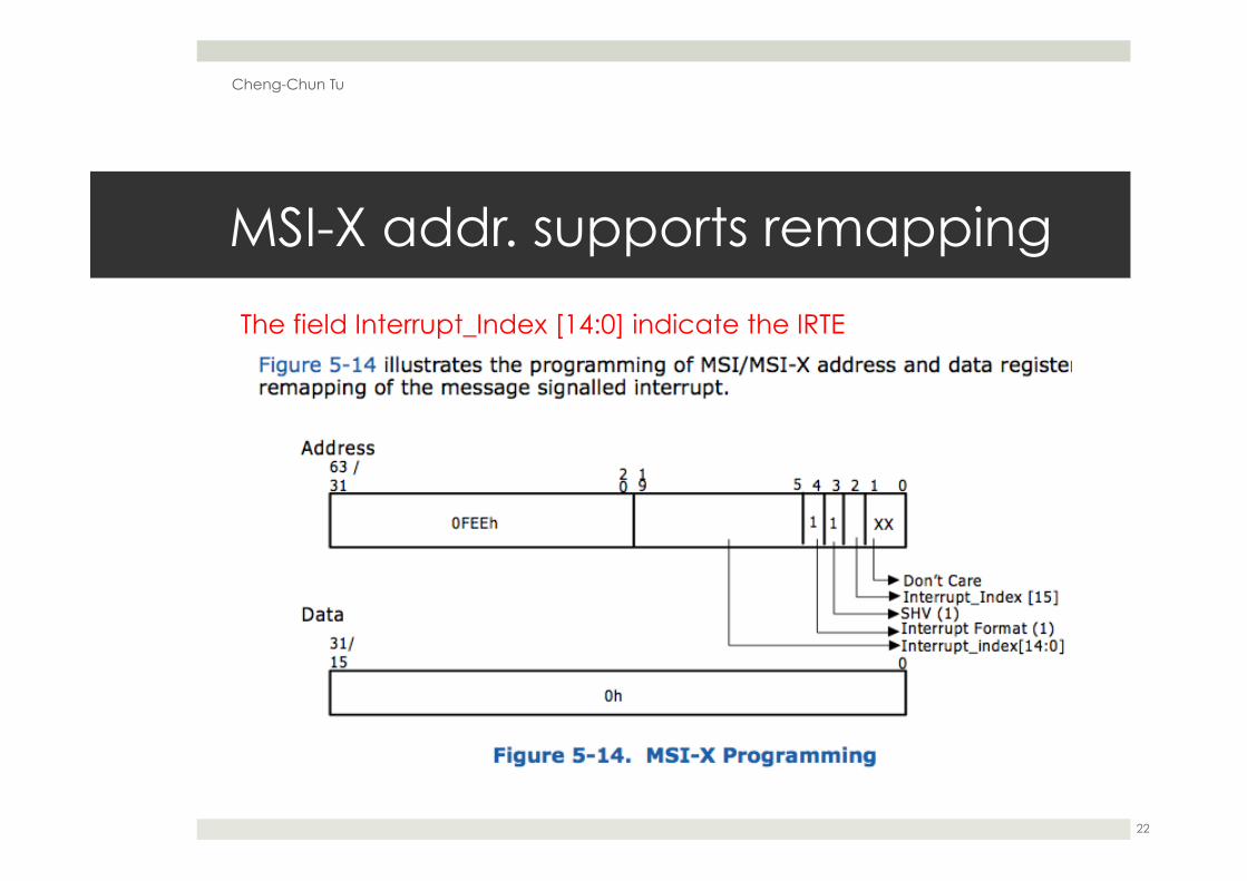
MSI-X addr. supports remapping
Cheng-Chun Tu
22
The field Interrupt_Index [14:0] indicate the IRTE

INTR: IRTE
Cheng-Chun Tu
23
Destination ID determines which CPU to INT, Vector determines the handler in IDT

MSI-X Address
Cheng-Chun Tu
24

MSI-X data
Cheng-Chun Tu
25
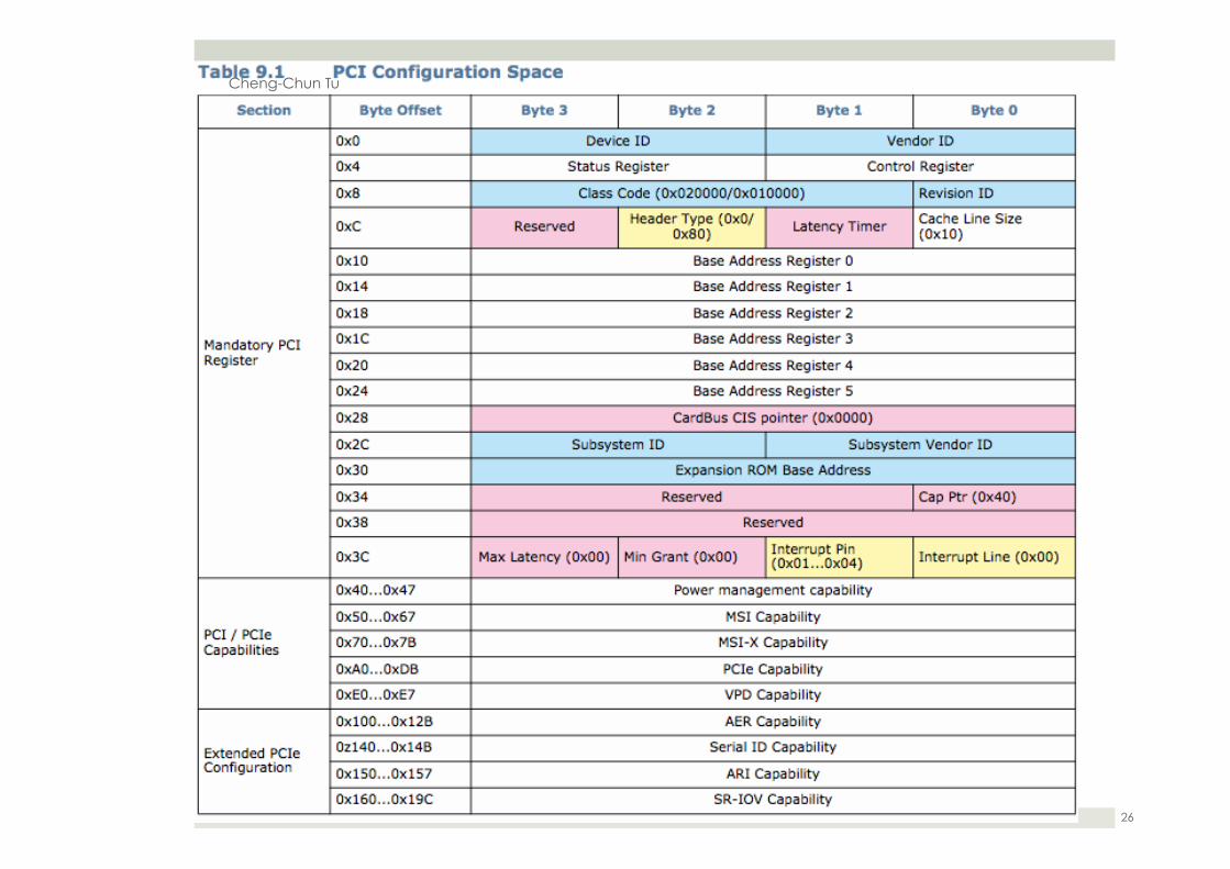
Cheng-Chun Tu
26

System Address Map
Cheng-Chun Tu
27

Example
¤ DeviceX has 3 MSI-X interrupt (RX/TX/MSG): ¤ In device A’s MSI-X table (addr, data), it has three entries ¤ (0xfee00518, 0), (0xfee00518, 1), (0xfee00518, 2) at entry 0,1,2
¤ Kernel creates 1:1 vector-to-entry mapping ¤ (65, 0), (66, 1), (67, 2), where vector table contains INT handler’s code ¤ 65: RX handler, 66: TX handler, 67: Msg handler
¤ An incoming packet triggers RX ¤ Device write (0xfee00518, 0) ¤ addr.handle: [19:5], data.subhandle: [15:0] bit ¤ Computed Interrupt index = addr.handle + data.subhandle = 40
¤ At IOMMU, IRTE at index 40 contains ¤ Destination ID = CPU0 ¤ Vector = 65 ¤ Write to CPU0’s APIC, CPU finds RX handler at index 40 in its IDT
Cheng-Chun Tu
28

References
¤ http://forum.osdev.org/viewtopic.php?f=1&t=24813&p=204113&hilit=William#p204113
Cheng-Chun Tu
29