interplay common services - avidresources.avid.com/supportfiles/attach/ics/ics 1.3...
TRANSCRIPT
Interplay® Common Services Version 1.3 Installation & Configuration Guide
ICS Version: 1.3 Document Version: 1.0.2
This document provides instructions to install and configure Avid Interplay Common Services (ICS) version 1.3 for use during with Interplay Central 1.3.x and Interplay Sphere.
Visit the ICS 1.3 Landing Page on the Avid Knowledge Base to get the latest versions of all ICS documentation (including this ReadMe)—updates are occasionally issued after initial release.
http://avid.force.com/pkb/articles/en_US/readme/Avid-Interplay-Common-Services-Version-1-3-Documentation
Note: Interplay MAM does not support ICS 1.3 for video playback. Interplay MAM 4.0.10, 4.1.2, and 4.2 require ICPS 1.2.5. Interplay MAM will support ICS for video playback in a future ICS release.
Copyright © 2013 Avid Technology
About ICS 1.3
Please see the Interplay Common Services 1.3 ReadMe and any ReadMe documents pertaining to the solution(s) by which ICS is used.
Document History
Date Revised Version Changes Made
01 Dec 2012 1.0 ICS 1.3 document release.
05 Dec 2012 1.0.1 Minor updates.
08 Feb 2013 1.0.2 Hyperlink errors corrected. Updated notes on ICDS installation. Updated appendix on SSL certificates.
ICPS 1.3 Installation & Configuration Guide
2
Contents
Welcome .................................................................................................................................................... 7
About this Guide ........................................................................................................................................ 8
Intended Audiences and Prerequisites ...................................................................................................... 8
Basic Installation Skills ............................................................................................................................ 8
Clustering Skills ....................................................................................................................................... 9
Deployment Options ................................................................................................................................ 10
Interplay Central – iNews Only ............................................................................................................. 10
Interplay Central – Interplay Production Only ..................................................................................... 11
Interplay Central – iNews and Interplay Production ............................................................................ 11
Interplay Sphere Only ........................................................................................................................... 12
Both Interplay Central and Interplay Sphere (Shared ICS) ................................................................... 13
Caching in ICS ........................................................................................................................................... 14
The Dedicated Caching Volume ........................................................................................................... 14
Caching for iOS Devices in Interplay Central ........................................................................................ 14
Caching for Sphere ............................................................................................................................... 14
Working with Linux .................................................................................................................................. 15
Installing Linux ...................................................................................................................................... 15
Linux Concepts ..................................................................................................................................... 15
Key Linux Directories ............................................................................................................................ 16
Linux Command Line ............................................................................................................................ 17
Linux Text Editor (vi) ............................................................................................................................. 18
Volumes in Linux .................................................................................................................................. 19
Clock Synchronization in Linux ............................................................................................................. 19
Time Zones in RHEL .............................................................................................................................. 19
RAIDs in ICS .............................................................................................................................................. 20
Introduction to Clustering ........................................................................................................................ 20
Working with Gluster ........................................................................................................................... 21
Obtaining the Software ............................................................................................................................ 21
Obtaining the ICS Installation Packages ............................................................................................... 21
Obtaining Red Hat Enterprise Linux ..................................................................................................... 22
Obtaining Gluster ................................................................................................................................. 22
Before You Begin ...................................................................................................................................... 23
ICPS 1.3 Installation & Configuration Guide
3
Make Sure the Host Solutions Are Installed and Running ................................................................... 23
Make Sure You Have the Following Items ............................................................................................ 23
Make Sure You Can Answer the Following Questions ......................................................................... 23
Make Sure You Have All the Information You Need ............................................................................ 25
Make Sure You Change the Default Passwords ................................................................................... 25
Installation Workflow............................................................................................................................... 25
Preparing the ICS Installation USB Key .................................................................................................... 28
Copying ICS and Linux to the USB Key .................................................................................................. 28
Copying Gluster to the USB Key ........................................................................................................... 29
Installing the Network Interface Cards .................................................................................................... 30
Installing NIC Cards for Interplay Central or Interplay Sphere ............................................................. 30
Physically Connecting the ICS Server to the Network or ISIS ................................................................... 31
Setting the System Clock and Disabling HP Power Saving Mode ............................................................ 31
Setting Up the RAID Level 1 Mirrored System Drives .............................................................................. 32
Setting Up the RAID Level 5 Cache Drives ............................................................................................... 34
Installing RHEL and the ICS Software ....................................................................................................... 35
Booting RHEL for the First Time ............................................................................................................... 37
Booting from the System Drive ............................................................................................................ 37
Changing the root Password ................................................................................................................ 38
Verifying the Date and Time................................................................................................................. 39
Setting the Time Zone .......................................................................................................................... 39
Editing the Network Connections ............................................................................................................ 40
Verifying the NIC Interface Name ........................................................................................................ 41
Swapping NIC Interface Names ............................................................................................................ 42
Removing the MAC Address Hardware References ............................................................................. 43
Configuring the Hostname and Static Network Route ......................................................................... 44
Creating the File Cache on the RAID ........................................................................................................ 45
Partitioning the RAID ............................................................................................................................ 46
Creating the Logical Volume and Mounting the Cache ........................................................................ 46
Installing the Interplay Central Distribution Service ................................................................................ 48
Determining Where to Install ICDS ...................................................................................................... 48
Before You Begin .................................................................................................................................. 49
Configuring ICS for Interplay Central and/or Interplay Sphere ............................................................... 50

ICPS 1.3 Installation & Configuration Guide
4
Before You Begin .................................................................................................................................. 51
Configuring the Interplay Central UI .................................................................................................... 52
Logging into Interplay Central .............................................................................................................. 53
Changing the Administrator Password ................................................................................................. 54
Configuring Interplay Production Settings ........................................................................................... 55
Configuring ICPS for Interplay .............................................................................................................. 56
Configuring ICPS for Interplay Central.................................................................................................. 57
Configuring the ISIS Connection(s) ....................................................................................................... 58
Mounting the ISIS System(s) ................................................................................................................ 59
Verifying Video Playback ...................................................................................................................... 60
Configuring Wi-Fi Only Encoding for Facility-Based iOS Devices ......................................................... 61
Clustering Workflow ................................................................................................................................ 61
Replicating the Cluster File Caches .......................................................................................................... 63
Before You Begin .................................................................................................................................. 63
Mounting the USB Key ......................................................................................................................... 64
Installing Gluster................................................................................................................................... 65
Creating the Trusted Storage Pool ....................................................................................................... 65
Configuring the GlusterFS Volumes ..................................................................................................... 66
Mounting the GlusterFS Volumes in Linux ........................................................................................... 68
Testing the Cache ................................................................................................................................. 70
Ensuring Gluster is On at Boot ............................................................................................................. 70
Setting up the Server Cluster ................................................................................................................... 70
Before You Begin .................................................................................................................................. 71
Double-checking the NIC Interface Names .......................................................................................... 71
Starting the Cluster Services ................................................................................................................ 73
Joining the Cluster ................................................................................................................................ 74
Post-Installation Steps ............................................................................................................................. 75
Monitoring ICS High-Availability and Load Balancing .......................................................................... 75
Taking a Node Off-Line Cluster ............................................................................................................. 76
Retrieving ICS Logs ............................................................................................................................... 76
Log Cycling ............................................................................................................................................ 77
Using SNMP Monitoring on the ICPS Server ........................................................................................ 77
Migrating the ICP Database from Windows to Linux ........................................................................... 78

ICPS 1.3 Installation & Configuration Guide
5
Backing up and Restoring the ICS Database ......................................................................................... 78
Appendix A: Handling Trusted Certificates .............................................................................................. 79
Built-In Browser Functionality .......................................................................................................... 79
SAN Certificates ................................................................................................................................ 80
Understanding the “Certificate Not Trusted” Warning ........................................................................ 80
Eliminating the Certificate not Trusted and Name Mismatch Warnings ............................................. 81
Generating a Self-Signed Certificate for a Single Server ...................................................................... 82
Generating a Self-Signed Certificate for a Server Cluster .................................................................... 84
Before You Begin .............................................................................................................................. 84
Adding Certificate Usage Passwords to the Interplay Central Properties File ..................................... 87
Configuring Google Chrome (Windows) .............................................................................................. 89
Configuring Internet Explorer (Windows) ............................................................................................ 93
Configuring Safari (Mac OS) ................................................................................................................. 97
Launching the Windows Import SSL Certificate Directly ...................................................................... 98
Obtaining a Trusted CA-signed Certificate ........................................................................................... 99
Adding a CA-Signed Certificate to the ICS Server ................................................................................. 99
The Interplay Central Application Properties File .............................................................................. 102
Appendix B: Migrating the Database with the User Management Utilities Tool .................................. 103
Appendix C: Installing the Chrome Extension for Interplay Central MOS Plug-Ins ................................ 104
Setting Up Your Browser .................................................................................................................... 104
Enabling MOS ..................................................................................................................................... 104
Uninstalling the Chrome Extension .................................................................................................... 104
Appendix D: Installation Pre-Flight Checklist ......................................................................................... 105
Default Password Information ........................................................................................................... 105
Contact Information ........................................................................................................................... 105
Hardware ............................................................................................................................................ 106
Software ............................................................................................................................................. 106
Network Settings ................................................................................................................................ 106
ICS Server Information ....................................................................................................................... 106
Cluster Information ............................................................................................................................ 107
iNews Information .............................................................................................................................. 108
Interplay Central and Interplay Sphere Information .......................................................................... 108
Interplay Production Information ...................................................................................................... 109

ICPS 1.3 Installation & Configuration Guide
6
ISIS Information .................................................................................................................................. 109
Copyright and Disclaimer ....................................................................................................................... 111

ICPS 1.3 Installation & Configuration Guide
7
Welcome
Welcome to the ICS Installation and Configuration Guide. This document will guide you through the installation and set up of the Interplay Common Services (ICS) software components. It provides step by step instructions to visually verify the hardware setup, install Linux and the ICS software, and configure the software systems that will make use of ICS. It also provides detailed steps for optional activities, for example: setting up a cluster of ICS servers, or configuring for an iPad-only deployment.
ICS is a set of software services running under the Linux operating system. ICS serves layouts for applications, provides user authentication, manages system configuration settings, and provides proxy-based playback of video assets over the network to web-based and mobile clients.
ICS supports several different Avid Integrated Media Enterprise (IME) solutions, including Interplay Central, and Interplay Sphere. ICS installs on its own set of servers, distinct from the IME solution it is supporting. Multiple ICS servers can be clustered together to obtain one or more of high-availability, load balancing and scalability.
Note: Refer to the “How to Buy Hardware for Interplay Common Services” guide for detailed information on hardware specifications and deployment options. The guide is available on the Avid Knowledge Base ICS 1.3 web page.
The installation and configuration steps vary depending on the deployment model, target hardware, and optional steps. For example, installations on qualified HP servers can use an express process involving a USB key and the supplied Red Hat Enterprise Linux kickstart (ks.cfg) file. Kickstart files are commonly used in Linux installs to automatically answer questions for hardware known in advance.
Note: All decisions pertaining to hardware, deployment model, optional activities (such as setting up a cluster), network connections (GigE vs 10GigE), must be made before beginning the installation. If these decisions have not been taken please consult an Avid representative.
Red Hat Enterprise Linux — sometimes just called Red Hat, but referred to in this guide as RHEL — is a commercially supported, open source version of the popular Linux operating system. No matter what the deployment model and target hardware, the installation of RHEL is mandatory. ICS requires RHEL 6.2. Do not install any OS updates, patches. Do not upgrade to RHEL 6.3 or higher. For more information on Red Hat see “Working with Linux” on page 15. RHEL licensing and support options are covered in the “How to Buy Hardware for Interplay Common Services” guide.
Note: Clock setting and synchronization play an important role in some ICS deployments. For a discussion of the issues associated with clock synchronization and using a time server to set the system clock, see “Clock Synchronization in Linux” on page 19.
Important: Search the Avid Knowledge Base ICS 1.3 web page for the most up-to-date ICS 1.3 Installation and Configuration Guide, which contains the latest information that might have become available after this document was published.
ICPS 1.3 Installation & Configuration Guide
8
About this Guide
This guide provides all the instructions you need to set up ICS 1.3. The installation and configuration is complex and can be difficult, particularly if you are unfamiliar with Linux.
The following tips will ensure a smooth installation:
Read the whole guide, thoroughly and all the way through, before beginning the installation process.
Gather all the information required to perform the install before you start. Waiting until the information is called for by an installation step will result in considerable delays.
For a list of required information, see “Appendix D: Installation Pre-Flight Checklist” on page 105.
Complete all the relevant sections in the pre-flight checklist for your deployment.
Intended Audiences and Prerequisites
This guide is aimed at the person responsible for performing a fresh install of ICS, or upgrading or maintaining an existing ICS installation. It can also be used by someone creating a cluster of ICS nodes out of a non-clustered setup. In particular, the following audiences have been identified:
Avid Professional Services: Avid personnel whose responsibilities include installing and
upgrading the ICS system, on-site at a customer’ facility.
Avid Channel Partners and Resellers: Selected organizations qualified by Avid to educate,
market, sell, install, integrate and provide support for the Avid product line, including ICS.
In-House Installers: Clients with a sophisticated in-house IT department that has expertise
in systems integration and Linux (including networking, port-bonding, etc). This kind of
person might be called on to add a new server to an already established cluster of ICS
servers, for example.
Basic Installation Skills
The following skills are needed to perform the basic installation:
Windows: Format a USB key, unzip files, etc.
Server: Access to the physical server, booting/rebooting, interrupting startup screens to enter BIOS and other utilities, navigating and altering BIOS, setting up RAIDs.
Network Interface Cards (NICs): Identify a NIC, knowledge of which NIC interface is being used.
Linux (install): Previous experience installing Linux is preferred but not essential, knowledge of manually installing RPM files will be helpful.

ICPS 1.3 Installation & Configuration Guide
9
Linux (general): Work with Linux directories (cd, mkdir, ls), create volumes, mount/unmount directories, volumes and devices (e.g. USB key), verify the status of a Linux service.
Linux (file editing): Use the Linux text editor (vi) to open/create files, add/delete text, save/close files, etc.
Networking: An understanding of network topologies and Ethernet protocols (TCP/IP), using ping command, verify/change a NIC card Ethernet interface (i.e. eth0).
System Clocks: Setting the system clock in BIOS and in Linux. For a discussion of system clock options, see “Clock Synchronization” on page 19.
Clustering Skills
The following skills are desirable for setting up a cluster of ICS nodes:
Gluster: Familiarity with Gluster, as it is used to create a shared pool of storage, including starting/stopping Gluster services, creating shared storage pools, creating GlusterFS volumes, etc.
Networking: A basic understanding of multicast and IP networking. An advanced understanding of networking in Linux would be helpful, but is not essential, since all instructions are provided.

ICPS 1.3 Installation & Configuration Guide
10
Deployment Options
ICS is a collection of software services designed to support a number of Avid enterprise solutions and deployment options. Since each deployment scenario has different hardware and software configuration requirements (and playback characteristics), it will be helpful to have a high-level overview of the deployment of interest before proceeding.
As noted, the installation follows one of these basic deployment models:
ICS for Interplay Central
o iNews only
o Interplay Production only
o iNews and Interplay Production
ICS for Interplay Sphere
ICS for Interplay Central and Interplay Sphere (Shared ICS)
This section provides an overview of each of these deployments.
Interplay Central – iNews Only One of the most straightforward deployments is ICS for Interplay Central in an iNews-only environment; that is, with connections to iNews but no connection to Interplay Production. In this deployment ICS provides the ability to browse and edit iNews content (queues, stories) from a remote web client. The ability to browse, play and edit associated video requires Interplay Production and is not provided by the iNews-only deployment.
Interplay Central for iNews:
The iNews-only deployment typically requires a RAID 1 (mirrored RAID) for the Linux operating system. Since ICS is not providing playback of any video assets, there is no need for caching, so the RAID 5 referred to in this guide is not required. Typically, a single ICS server is sufficient. Two ICS servers configured as a cluster provide high-availability.
ICPS 1.3 Installation & Configuration Guide
11
Note: The iNews-only deployment can be on smaller, less expensive server hardware. Refer to the “How to Buy Hardware for Interplay Common Services” guide for detailed information on hardware specifications and deployment options. The guide is available on the Avid Knowledge Base ICS 1.3 web page.
Interplay Central – Interplay Production Only
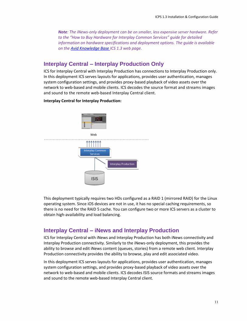
ICS for Interplay Central with Interplay Production has connections to Interplay Production only. In this deployment ICS serves layouts for applications, provides user authentication, manages system configuration settings, and provides proxy-based playback of video assets over the network to web-based and mobile clients. ICS decodes the source format and streams images and sound to the remote web-based Interplay Central client.
Interplay Central for Interplay Production:
This deployment typically requires two HDs configured as a RAID 1 (mirrored RAID) for the Linux operating system. Since iOS devices are not in use, it has no special caching requirements, so there is no need for the RAID 5 cache. You can configure two or more ICS servers as a cluster to obtain high-availability and load balancing.
Interplay Central – iNews and Interplay Production ICS for Interplay Central with iNews and Interplay Production has both iNews connectivity and Interplay Production connectivity. Similarly to the iNews-only deployment, this provides the ability to browse and edit iNews content (queues, stories) from a remote web client. Interplay Production connectivity provides the ability to browse, play and edit associated video.
In this deployment ICS serves layouts for applications, provides user authentication, manages system configuration settings, and provides proxy-based playback of video assets over the network to web-based and mobile clients. ICS decodes ISIS source formats and streams images and sound to the remote web-based Interplay Central client.
ICPS 1.3 Installation & Configuration Guide
12
Interplay Central with iNews and Interplay Production:
This deployment typically requires two HDs configured as a RAID 1 (mirrored RAID) for the Linux operating system. In a configuration where the iOS application is used, the ICS server should also have a RAID 5 cache drive. You can configure two or more ICS servers as a cluster to obtain high-availability and load balancing.
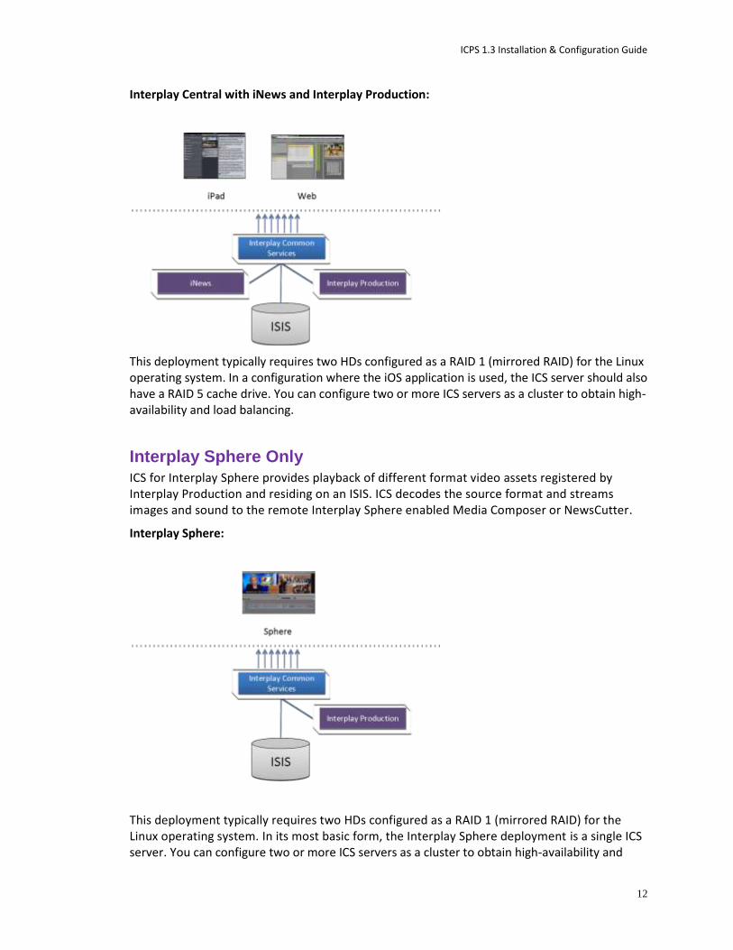
Interplay Sphere Only ICS for Interplay Sphere provides playback of different format video assets registered by Interplay Production and residing on an ISIS. ICS decodes the source format and streams images and sound to the remote Interplay Sphere enabled Media Composer or NewsCutter.
Interplay Sphere:
This deployment typically requires two HDs configured as a RAID 1 (mirrored RAID) for the Linux operating system. In its most basic form, the Interplay Sphere deployment is a single ICS server. You can configure two or more ICS servers as a cluster to obtain high-availability and

ICPS 1.3 Installation & Configuration Guide
13
load balancing. There are no special caching requirements (no RAID 5 cache) in an Interplay Sphere-only deployment.
Both Interplay Central and Interplay Sphere (Shared ICS) Interplay Central and Interplay Sphere can easily share the same ICS server(s). In this deployment, ICS serves layouts for applications, provides user authentication, and manages system configuration settings. ICS also provides proxy-base playback over the network of different format video assets registered by Interplay Production and residing on an ISIS. ICS decodes the source format and streams images and sound to the remote web-based Interplay Central and/or Interplay Sphere clients.
This is the most sophisticated deployment model, since other elements can also be present, such as iNews with corresponding iOS device applications.
Interplay Central and Interplay Sphere (Shared ICS):
This deployment typically requires a RAID 1 (mirrored RAID) for the Linux operating system. In a configuration with iOS devices (as with iNews), the ICS server should also have a RAID 5 cache drive. If iOS devices are not deployed, it has no RAID 5 cache requirements. You can configure two or more ICS servers as a cluster to obtain high-availability and load balancing.
ICPS 1.3 Installation & Configuration Guide
14
Caching in ICS
In its work to provide proxy-based playback of video assets over a network, ICS generates temporary files in certain workflows. By default, ICS caches temporary files on the system drive. Better performance is achieved by allocating a RAID 5 volume for the temporary files.
The Dedicated Caching Volume All ICS servers require a RAID 1 that mirrors the operating system across two HD drives. Some deployments also require a RAID 5 volume consisting of the remaining disks in the enclosure, used exclusively for ICS file caching. In a RAID 5 volume, the disk controller automatically distributes (stripes) data across all the disks in the RAID 5, yielding increased performance and redundancy.
In an ICS server cluster the RAID 5 file cache is taken one step further. An open source software solution called Gluster is used to replicate the contents of the RAID 5 volumes across each server in the cluster. In this way, each ICS server in the cluster can make use of file data already transcoded cached by the others.
Caching for iOS Devices in Interplay Central In an Interplay Central deployment where an iOS application is used, the ICS server should have a RAID 5 cache drive.
Caching for Sphere Interplay Sphere caches the video and audio it receives locally. There is no ICS server-side caching, thus no RAID 5 requirements.
ICPS 1.3 Installation & Configuration Guide
15
Working with Linux
As noted, RHEL is a commercially supported, open source version of the Linux operating system. If you have run DOS commands in Windows or have used the Mac terminal window, the Linux environment will be familiar to you. While many aspects of the ICS installation are automated, much of it requires entering commands and editing files using the Linux command-line.
Note: RHEL is not free, and Avid does not redistribute it or include it as part of the ICS installation. RHEL licensing and support options are covered in the “How to Buy Hardware for Interplay Common Services” guide.
Installing Linux
Installations on qualified HP servers can use an express process involving a USB key and the supplied RHEL kickstart (ks.cfg) file. Kickstart files are commonly used in Linux installs to automate the OS installation. A kickstart file automatically answers questions posed by the Linux installer, for hardware known in advance.
Since RHEL is a licensable product, redistribution by Avid is not possible. However, the ICS installation package includes a Windows executable (ISO2USB) for creating a bootable USB drive from a RHEL installation DVD or image (.iso) file. We use ISO2USB to prepare the USB drive to install the ICS components too.
Linux Concepts Once RHEL is installed you can begin the work of setting up the server for ICS. This involves simple actions such as verifying the system time. It also involves more complex actions, such as verifying and modifying hardware settings related to networking, and editing files. Depending on the deployment, you may also be required to create logical volumes and perform other advanced actions.
Advance knowledge of the following Linux concepts will be helpful:
root user: The root user (sometimes called the “super” user) is the Linux user with highest privileges. All steps in the installation are performed as root.
mounting: Linux does not recognize HDs or removable devices such as USB keys unless they are formally mounted.
files and directories: In Linux, everything is a file or a directory.
ICPS 1.3 Installation & Configuration Guide
16
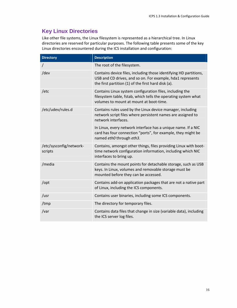
Key Linux Directories Like other file systems, the Linux filesystem is represented as a hierarchical tree. In Linux directories are reserved for particular purposes. The following table presents some of the key Linux directories encountered during the ICS installation and configuration:
Directory Description
/ The root of the filesystem.
/dev Contains device files, including those identifying HD partitions, USB and CD drives, and so on. For example, hda1 represents the first partition (1) of the first hard disk (a).
/etc Contains Linux system configuration files, including the filesystem table, fstab, which tells the operating system what volumes to mount at mount at boot-time.
/etc/udev/rules.d Contains rules used by the Linux device manager, including network script files where persistent names are assigned to network interfaces.
In Linux, every network interface has a unique name. If a NIC card has four connection “ports”, for example, they might be named eth0 through eth3.
/etc/sysconfig/network-scripts
Contains, amongst other things, files providing Linux with boot-time network configuration information, including which NIC interfaces to bring up.
/media Contains the mount points for detachable storage, such as USB keys. In Linux, volumes and removable storage must be mounted before they can be accessed.
/opt Contains add-on application packages that are not a native part of Linux, including the ICS components.
/usr Contains user binaries, including some ICS components.
/tmp The directory for temporary files.
/var Contains data files that change in size (variable data), including the ICS server log files.
ICPS 1.3 Installation & Configuration Guide
17
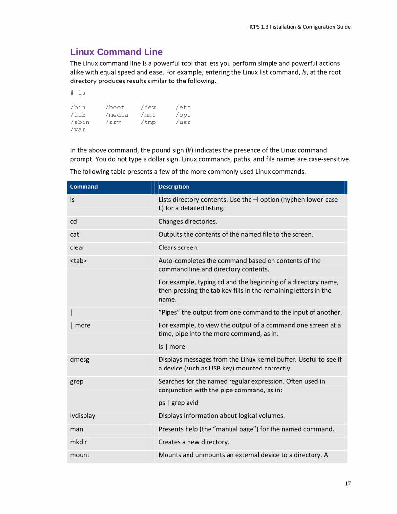
Linux Command Line The Linux command line is a powerful tool that lets you perform simple and powerful actions alike with equal speed and ease. For example, entering the Linux list command, ls, at the root directory produces results similar to the following.
# ls
/bin /boot /dev /etc
/lib /media /mnt /opt
/sbin /srv /tmp /usr
/var
In the above command, the pound sign (#) indicates the presence of the Linux command prompt. You do not type a dollar sign. Linux commands, paths, and file names are case-sensitive.
The following table presents a few of the more commonly used Linux commands.
Command Description
ls Lists directory contents. Use the –l option (hyphen lower-case L) for a detailed listing.
cd Changes directories.
cat Outputs the contents of the named file to the screen.
clear Clears screen.
<tab> Auto-completes the command based on contents of the command line and directory contents.
For example, typing cd and the beginning of a directory name, then pressing the tab key fills in the remaining letters in the name.
|
| more
“Pipes” the output from one command to the input of another.
For example, to view the output of a command one screen at a time, pipe into the more command, as in:
ls | more
dmesg Displays messages from the Linux kernel buffer. Useful to see if a device (such as USB key) mounted correctly.
grep Searches for the named regular expression. Often used in conjunction with the pipe command, as in:
ps | grep avid
lvdisplay Displays information about logical volumes.
man Presents help (the “manual page”) for the named command.
mkdir Creates a new directory.
mount Mounts and unmounts an external device to a directory. A

ICPS 1.3 Installation & Configuration Guide
18
Command Description
unmount device must be mounted before its contents can be accessed.
ps Lists the running processes.
psswd Changes the password for the logged-in user.
service Runs an initialization script.
e.g. service avid-all
udevadm Requests device events from the Linux kernel. Can be used to replay device events and create/update the 70-persistent-net.rules file.
e.g. udevadm trigger --action=add
vi Starts a vi editing session.
Linux Text Editor (vi) Linux features a powerful text editor called vi. To invoke vi, type the vi command followed by the target file at the command prompt.
$ vi <filename>
Vi operates in one of two modes, insert mode and command mode. Insert mode lets you perform text edits – insertion, deletion, etc. Command mode acts upon the file as a whole – for example, to save it or to quit without saving.
The following table presents a few of the more useful vi commands.
Key Press Description
i Insert text before the cursor, until you press <Esc>
I Insert text at beginning of current line
a Insert text after the cursor
A Insert text at end of current line
: Switch to command mode
<Esc> Turn off Insert mode
w Next word
b Previous word
Shift-g Move cursor to last line of the file
D Delete remainder of line
x Delete character under the cursor
dd Delete current line
:wq Write file and quit vi
:q! Quit without writing
For a series of short and helpful vi tutorials, see:
ICPS 1.3 Installation & Configuration Guide
19
http://www.unix-manuals.com/tutorials/vi/vi-in-10-1.html
Volumes in Linux For those more familiar with Windows, the steps to creating usable volume in Linux are similar to preparing a new HD for use in Windows.
In Windows, you initialize the disk, create a partition, and assign it a drive letter. You must then format the disk, specify its file system, its allocation unit size, and assign it a volume label.
In Linux, you must also initialize the disk (this takes place during RHEL installation) and create a partition. You also format the disk and specify its file system and sector size. Volume labels do not apply, but have a parallel in the Linux device names (for example /dev/hda or /dev/hdb in the case of HDs).
Linux builds up to a usable volume in a series of “layers”, each building upon the previous. From lowest to highest they are physical volumes, volume groups, logical volumes. The filesystem is built on top of the logical volume.
Clock Synchronization in Linux The basic mechanism for clock synchronization under Linux is the Network Time Protocol (NTP) daemon, ntpd, which can be used to automatically maintain synchronization of the system clock with a specified time server. The time server might be a master clock within a firewall, or one of the numerous time-servers based on an atomic clock and available via the internet.
This guide provides the instructions for setting the system clock “by hand”. Depending on the facility’s time infrastructure, you may wish to expand on the instructions provided, to set the system clock more appropriately:
From a known source of accurate time such as an NTP daemon
From the ISIS time
It is particularly important when setting up a cluster of ICS nodes that each node should have the same time.
Time Zones in RHEL Like most operating systems, RHEL needs to know the time zone in which it is operating. In RHEL this is set by assigning geographic information and/or a specific time zone. For example the following are all valid time zone specifications in RHEL:
America/EST
America/Los_Angeles
Australia/Sydney
Brazil/East
Europe/Amsterdam

ICPS 1.3 Installation & Configuration Guide
20
The installation script automatically sets the time zone to Eastern Standard Time. You will have the opportunity to set the time zone to something more appropriate when you boot RHEL for the first time.
RAIDs in ICS
RAID stands for redundant array of inexpensive (or independent) disks. RAIDs are used in ICS to provide data redundancy and for efficiency in caching large amounts of data across multiple disks. On supported HP servers, you implement these RAIDs at the level of the HP disk controller, using the HP RAID configuration BIOS utility.
ICS makes use of the following RAID types:
RAID 1: All ICS implementations require a RAID 1 (mirror) for the system (OS) drive. This RAID provides redundancy in the event of HD failure.
RAID 5: Certain deployments also require additional disks configured as a RAID 5 (data striping with parity blocks) for caching file data. This RAID provides redundancy and increased performance.
The following deployments typically benefit from a RAID 5 configuration:
Interplay Central: Interplay Central installations deploying the iNews iOS (Apple mobile operating system) app require a RAID 5 cache volume. In this case, media on the ISIS are transcoded to MPEG-TS (MPEG-2 transport stream), and stored.
With regards to particular servers:
HP DL360: The HP DL360 may have up to 8 drives present. Configure two as RAID 1 for the system drive. The additional drives (up to 6), if present, can be configured a RAID 5 volume for caching per deployment requirements.
Other Servers: Other servers will have different hard drive capacities. Configure two drives as RAID 1 for the system drive and the remaining drives as a RAID 5 volume for caching.
Introduction to Clustering
Redundancy and scale for ICS is obtained by setting up a cluster of two or more servers. Within the cluster, requests for media are automatically distributed to the available servers. An ICS server cluster provides the following:
Load balancing. All incoming playback connections are routed to a cluster IP address, and are subsequently distributed evenly to the nodes in the cluster.
High-availability. If any node in the cluster fails, connections to that node will automatically be redirected to another node.
Replicated Cache: The media transcoded by one node in the cluster is replicated in the other nodes.
ICPS 1.3 Installation & Configuration Guide
21
Cluster monitoring. You can monitor the status of the cluster by entering a command. If a node fails (or if any other serious problem is detected by the cluster monitoring service), an e-mail is automatically sent to one or more e-mail addresses.
Generally speaking, clusters consist of nodes with identical hardware profiles. However, this is not required. You can use different hardware profiles for the servers in a cluster.
Working with Gluster
Recall that the ICS server transcodes media from the format in which it is stored on the ISIS (or standard filesystem storage) into an alternate delivery format, such as an FLV or MPEG-2 Transport Stream.
In a deployment with a single ICS server, the ICS server maintains a cache where it keeps recently-transcoded media. In the event that the same media is requested by the web client again, the ICS server delivers the cached media, avoiding the need to re-transcode.
In an ICS cluster, the cache maintained by each ICS server is replicated across the others. Each ICS server sees and has access to all the media transcoded by the others. When one ICS server transcodes media, the other ICS servers can also make use of it, without re-transcoding.
The replication process is set up and maintained by Gluster, an open source software solution for creating shared filesystems. In ICS, Gluster manages data replication using its own highly efficient network protocol.
For more information on Gluster, see: http://www.gluster.org.
Note: The correct functioning of the cluster cache requires that the clocks on each server in the cluster are set to the same time. This is done in “Setting the System Clock and Disabling HP Power Saving Mode” on page 31.
Obtaining the Software
To perform the installation, the following software is required
ICS Installation Packages (required): A zip file containing Windows and Linux software needed for the installation.
RHEL 6.2 (required): The operating system installed on the server.
Gluster (optional): An open source software package used to mirror the file caches in a server cluster.
Obtaining the ICS Installation Packages On a Windows machine with an internet connection, log in to your Avid Download Center account (or Avid Master Account) and download it. The ICS installation package zip file has a name of the form ICS_v<version>.zip.
For example:
ICS_v1.3.zip

ICPS 1.3 Installation & Configuration Guide
22
It contains the following directories:
Item Description
CentralDistributionService Interplay Central Distribution Service (ICDS) installation program. This Interplay service coordinates jobs with Avid Media Services for sequence mixdowns and send to playback
USB_ICS_<version>.zip The ICS Server Installation package. Includes ISO2USB. Used to create the ICS installation USB key.
STPEncode STP Encode service. This service exports and encodes Long GOP media, then passes the media to the Transfer Engine for a send-to-playback operation. The STP Encode service supports various XDCAM media formats.
Transcode Interplay Transcode service. This service mixes down audio for script sequences and checks the sequence in to the Interplay Engine. No video mixdown is required when sending a script sequence to a playback device.
Transcode_Patch An update to the Interplay Transcode service.
Obtaining Red Hat Enterprise Linux Log in to your Red Hat Network account and download the DVD image (.iso) file or purchase a DVD. Either format can be used for the ICS installation.
Note: At the time of this document’s publication, the RHEL 6.2 ISOs were available by choosing the latest RHEL EUS Server 6 ISO from the Downloads page, then expanding the “View ISO Images for Older Releases” at the bottom of that page. RHEL 6.2 downloads did not appear in the main downloads list. RHEL 6.3 is not supported.
Note: ICS requires RHEL 6.2. Do not install any OS updates or patches. Do not upgrade to RHEL 6.3 or higher.
Obtaining Gluster Navigate to the download directory at gluster.org containing the GlusterFS version supported by ICS:
http://download.gluster.org/pub/gluster/glusterfs/3.3/3.3.1/RHEL/epel-6Server/x86_64
Download following packages:
glusterfs-3.3.1-1.el6.x86_64.rpm
glusterfs‐fuse‐3.3.1‐1.el6.x86_64.rpm
glusterfs‐server‐3.3.1‐1.el6.x86_64.rpm
glusterfs‐geo‐replication‐3.3.1‐1.el6.x86_64.rpm
ICPS 1.3 Installation & Configuration Guide
23
Note: If the specified version of Gluster is no longer available, contact your Avid representative.
Before You Begin
Make sure you have everything in place to ensure an efficient and successful installation. Do not proceed with the installation if something is missing.
Make Sure the Host Solutions Are Installed and Running The host system(s) for the deployment must already be installed, set up, and running:
iNews and/or Interplay Production
Sphere-enabled Media Composer or NewsCutter
ISIS
Make Sure You Have the Following Items The following items are needed for the installation:
ICS server(s), physically connected to the network and/or ISIS
ICS installation package (USB_ICS_v1.3.zip)
RHEL 6.2 installation image (.iso) file or DVD media
Gluster RPM packages (optional)
8GB USB key (for installations on supported HP hardware)
Windows XP/Vista/7 laptop or desktop computer with an Internet connection and a supported web browser (e.g. Google Chrome)
Note: It is particularly important that the server(s) on which you are installing the ICS software should be physically installed in the engineering environment, and the appropriate ISIS and/or the house network connection(s) should be known to you.
You also require access to the ICS server console(s):
Directly by connecting a monitor and keyboard to the server
Remotely via KVM (keyboard, video and mouse) switch, or comparable solution
Using SSH from another machine’s command prompt or shell. On Windows, Putty.exe is a good option: http://www.chiark.greenend.org.uk/~sgtatham/putty/download.html
Make Sure You Can Answer the Following Questions If you do not know the answers to all of the following questions, review the hardware
specifications in your possession, the deployment model you are pursuing and the
environment into which ICS is being installed, before proceeding.

ICPS 1.3 Installation & Configuration Guide
24
What kind of server? HP or Other.
ICS supports Interplay Central and Sphere on HP hardware only.
What kind of server setup? Single or Cluster.
A server cluster provides high-availability and load-balancing. The OS and ICS install
identically on each server in the cluster, but additional steps are required to configure
the servers as a cluster. Further some configuration steps are not needed on the non-
master nodes.
What kind of RAIDs are required? RAID 1 and/or RAID 5?
All ICS servers require a RAID 1 that mirrors the operating system across two HD drives.
Optionally, some deployments will benefit from a RAID 5 in which ICS cache data is
distributed across the remaining disks in the enclosure.
Whether or not your deployment requires (or would benefit from) a RAID 5 cache is a
decision that is beyond the scope of this document; however, the subject is presented in
“Caching in ICS” on page 14.
Static or Dynamic IP addresses?
All ports and bonded ports require IP addresses which can be dynamic or static. Work
with your network administrator to make this determination. Static IP addresses are
recommended.
Is this a shared ICS setup? Interplay Central and Interplay Sphere?
An ICS server or cluster can serve Interplay Central and Interplay Sphere simultaneously.
In this case, simply install an ICS server or ICS server cluster as indicated in this
document.
Are you deploying the Interplay Central iNews iOS app? Yes or No.
For Interplay Central installations deploying the iNews app for iOS (Apple mobile
operating system) devices such as an iPhone or iPad, a RAID 5 is required for server-side
caching.
What kind of clock setting/synchronization is required?
Clock setting and synchronization play an important role in some deployments,
particularly when creating a cluster. For a discussion, see “Clock Synchronization in
Linux” on page 19.

ICPS 1.3 Installation & Configuration Guide
25
Make Sure You Have All the Information You Need
During the ICS installation procedures, you are required to enter a great deal of information pertaining to the ICS servers, network settings, IP addresses, system administrator email addresses, and so on. It is important to gather this information before you begin. Waiting until the information is called for by an installation step will result in considerable delays.
For a list of information required to perform the install, see “Appendix D: Installation Pre-Flight Checklist” on page 105.
Make Sure You Change the Default Passwords For reasons of security it is strongly recommended that you change the default administrator-level passwords at the first opportunity. The RHEL installation script sets up a default login password for the root user (the Linux user with administrator privileges). Similarly, Interplay Central is supplied with a default user name and password for the administrator.
RHEL: Change the root password when you boot into Linux for the first time.
Interplay Central: Change the Administrator default password the first time you log in to the Interplay Central UI.
Before you begin obtain the new passwords from the customer where the system is being installed.
Installation Workflow
The following table describes each of the main installation steps.
If you are setting up a server cluster, be sure to read “Clustering Workflow” on page 61 too.
Step Task Time Est.
1 Appendix D: Installation Pre-Flight Checklist 1–2 hr varies
Make sure you have all the information related to the server hardware (including disk drives and NIC cards in the enclosure), network topography, IP addresses, etc., required to perform installation.
2 Obtaining the Software varies
If you are missing any software, this section tells you how to obtain it.
3 Before You Begin varies
A quick check to make sure you have everything in place for an efficient and successful installation.
4 Preparing the ICS Installation USB Key 1 hr
In this procedure, you create the USB key you will use to install the ICS software.
Note: This step is for HP servers only.

ICPS 1.3 Installation & Configuration Guide
26
Step Task Time Est.
5 Installing the Network Interface Cards 30 min
This step explains the slots where the NIC cards should be placed to simplify the software installation and configuration.
6 Physically Connecting the ICS Server to the Network or ISIS 30 min
In this step you ensure the ICS server is connected to your network and its ISIS.
7 Setting the System Clock and Disabling HP Power Saving Mode 15 min
Before installing the Operating System, you must make a few changes in the BIOS.
8 Setting Up the RAID Level 1 Mirrored System Drives 5 min
You make use of two of the server’s hard disks to create a mirrored RAID disk array for the operating system. This is done in the BIOS.
9 Setting Up the RAID Level 5 Cache Drives 5 min
In this step you create a RAID 5 disk array for the file cache used by ICS to store proxies.†
Note: This step is required only if you are deploying iOS devices in Interplay Central.†
10 Installing RHEL and the ICS Software 20 min
In this step you install RHEL and ICS on the RAID 1 disk array.
11 Booting RHEL for the First Time 10 min
Like most operating systems, the first time you boot RHEL you need to set some system information.
12 Editing the Network Connection 15 min
In this step you make sure the physical interface used to connect the ICS server to the network is called eth0.
13 Creating the File Cache on the RAID 15 min
Here, you tell ICS to use the RAID 5 disk array for its file cache.
Note: This step is required only if you are deploying iOS devices in Interplay Central.†
14 Installing the Interplay Central Distribution Service 5 min
Install and configure the Interplay service that coordinates jobs with Avid Media Services. This step is performed on a Windows machine in the Media Services network.
Note: ICDS is only required for Interplay Central, and requires Interplay Production.
ICPS 1.3 Installation & Configuration Guide
27
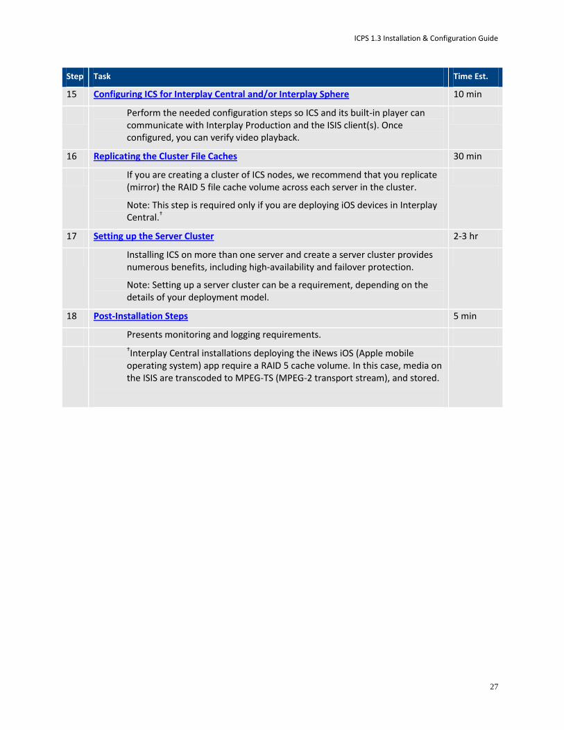
Step Task Time Est.
15 Configuring ICS for Interplay Central and/or Interplay Sphere 10 min
Perform the needed configuration steps so ICS and its built-in player can communicate with Interplay Production and the ISIS client(s). Once configured, you can verify video playback.
16 Replicating the Cluster File Caches 30 min
If you are creating a cluster of ICS nodes, we recommend that you replicate (mirror) the RAID 5 file cache volume across each server in the cluster.
Note: This step is required only if you are deploying iOS devices in Interplay Central.†
17 Setting up the Server Cluster 2-3 hr
Installing ICS on more than one server and create a server cluster provides numerous benefits, including high-availability and failover protection.
Note: Setting up a server cluster can be a requirement, depending on the details of your deployment model.
18 Post-Installation Steps 5 min
Presents monitoring and logging requirements.
†Interplay Central installations deploying the iNews iOS (Apple mobile operating system) app require a RAID 5 cache volume. In this case, media on the ISIS are transcoded to MPEG-TS (MPEG-2 transport stream), and stored.

ICPS 1.3 Installation & Configuration Guide
28
Preparing the ICS Installation USB Key
Installing ICS requires a bootable USB key containing all the files required for installing ICS, including RHEL. In this step you prepare the USB key.
For this procedure you require the following items:
The ICS installation package USB_ICS_<version>.zip
RHEL 6.2 installation image (.iso) file or DVD media
Note: Only RHEL 6.2 OS is supported. Do not install patches, updates, or upgrade to RHEL 6.3.
An 8GB USB key
A Windows XP/Vista/7 laptop or desktop computer
Follow this procedure only if you are installing ICS software components on a supported HP server.
Copying ICS and Linux to the USB Key Due to licensing restrictions, Avid is not able to redistribute the RHEL installation media. You must download the RHEL installation image (.iso) file from Red Hat directly—or get it from the RHEL Installation DVD that came with your ICS server—then copy the image file to the USB as instructed here.
Note: Make sure the RHEL 6.2 image (.iso) file is accessible locally (preferable) or over the network from your computer. You should complete this procedure with only the USB key you’re preparing inserted in the server. If you have more than one USB key inserted, make sure you choose the right one when performing this procedure.
To prepare the ICS Installation USB key:
1. Log into a Windows laptop or desktop.
2. Format the USB key as a FAT32 volume.
3. Unzip the USB_ICS_<version>.zip file to the desktop (or your preferred destination directory).
4. Browse to the unzipped USB_ICS_<version> folder.
5. Double-click iso2usb.exe to launch the application.
6. Choose the Diskimage radio button then browse to the RHEL.iso file (named rhel-server-6.2-x86_64-dvd or similar).
7. Verify the Hard Disk Name and USB Device Name are correct:
Hard Disk Name: sdb
USB Device Name: sda
Note: These values have changed since RHEL 6.0, where the hard disk name was sda and the USB device name was sdb.

ICPS 1.3 Installation & Configuration Guide
29
8. In the “Additional Files” field browse to the USB_ICS<version> folder on the desktop (or wherever you expanded it to) and then select the directory.
Select the directory name itself. Do not enter the directory and select the contents.
9. Click OK in the main dialog.
10. A process begins to copy the RHEL image (.iso) file and the ICS installation files to the USB key.
The process takes 20-30 minutes. Once complete, the USB key has everything it needs for a complete RHEL and ICS installation.
Note: Copying the RHEL image (.iso) file to the USB key is a one-time process. To install ICS to more than one server, or to re-install ICS, you do not need to repeat these steps.
To prepare for mirroring cluster file caches, proceed to “Copying Gluster to the USB Key” on page 29.
Otherwise, proceed to “Installing the Network Interface Cards” on page 30.
Copying Gluster to the USB Key To prepare for mirroring the file caches in a cluster setup, copy the GlusterFS RPMs you downloaded earlier to the USB key.
Note: This step is only for those setting up a cluster of ICS servers in an Interplay Central deployment that includes the iNews app for iOS devices. If you think you might set up a cluster in the future, perform this step now to ensure availability of compatible Gluster software.
For this procedure you require the following items:
An 8GB USB key
glusterfs-3.3.1-1.x86_64.rpm
glusterfs‐fuse‐3.3.1‐1.el6.x86_64.rpm
glusterfs‐server‐3.3.1‐1.el6.x86_64.rpm
glusterfs‐geo‐replication‐3.3.1‐1.el6.x86_64.rpm
A Windows XP/Vista/7 laptop or desktop computer
It is recommended that you copy the files to the ICS installation USB key. (Advanced Linux users may wish to create a network share to install these components instead.)
To add GlusterFS to the ICS Installation USB key:
1. Log into the Windows laptop or desktop where you saved the Gluster RPM packages.
2. Create a directory called Gluster at the root level on the USB key.
3. Copy the RPM packages to the new directory.
Proceed to “Installing the Network Interface Cards” on page 30.

ICPS 1.3 Installation & Configuration Guide
30
Installing the Network Interface Cards
As already noted, for Interplay Central and Interplay Sphere, ICS provides a number of services, including playback of video assets registered by Interplay Production and residing on an ISIS. ICS decodes the source format and streams images and sound to the remote web-based Interplay Central and/or Interplay Sphere clients. The connection from the ICS server to the ISIS must be over a Zone 1, Zone 2, or Zone 3 connection, using a GigE or 10GigE network interface.
In this procedure, you visually verify the correct Network Interface Cards (NICs) have been installed.
Note: Refer to the “How to Buy Hardware for Interplay Common Services” guide for detailed information on hardware specifications and deployment options. The guide is available on the Avid Knowledge Base ICS 1.3 web page.
Installing NIC Cards for Interplay Central or Interplay Sphere
The HP DL360 G8 has a full height PCI slot in the upper left corner. Use this slot for either the Myricom 10GigE or the recommended Intel PROset (e1000) based quad-port GigE NIC.
HP DL360 backplane (indicating Myricom 10GigE):
HP DL360 backplane (indicating 4-Port GigE):
Proceed to “Physically Connecting the ICS Server to the Network or ISIS” on page 31.
Myricom 10GigE
4-Port GigE
ICPS 1.3 Installation & Configuration Guide
31
Physically Connecting the ICS Server to the Network or ISIS
For a successful Interplay Central and/or Interplay Sphere installation, the ICS server(s) must be installed and connected to the ISIS via a Zone 1 (direct), Zone 2 (through a switch) or Zone 3 connection. iNews-only deployments do not require any ISIS connection.
Note: This applies to Interplay Central and Interplay Sphere deployments only.
Proceed to “Setting the System Clock and Disabling HP Power Saving Mode” on page “31”.
Setting the System Clock and Disabling HP Power Saving Mode
To ensure the smooth installation of RHEL and ICS, the system clock must be set. When setting up an ICS node cluster, setting the system clocks accurately is particularly important.
HP servers are frequently shipped with BIOS settings set to Power-Saving mode. ICS is makes intensive use of the server’s CPUs and memory, especially when under heavy load. You will get much better performance by ensuring that the server is set to operate at Maximum Performance.
Note: While setting the system clock and power saving mode can be done after the installation process, we recommend making the change immediately.
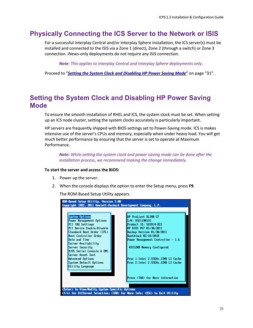
To start the server and access the BIOS:
1. Power up the server.
2. When the console displays the option to enter the Setup menu, press F9.
The ROM-Based Setup Utility appears.

ICPS 1.3 Installation & Configuration Guide
32
3. Choose Date and Time and press Enter.
Date and Time options appear.
Set the date (mm-dd-yyyy) and time (hh:mm:ss).
4. Press Enter to save the changes and return to the Setup Utility menu.
5. Choose Power Management Options.
Power Management options appear.
6. Choose HP Power Profile.
Power Profile options appear.
7. Choose Maximum Performance.
You are returned to the HP Power Management options menu.
8. Press Esc to return to main menu.
9. Exit the Setup utility <esc> and press F10 to save.
The server reboots with new options.
Proceed to “Setting Up the RAID Level 1 Mirrored System Drives” on page 32.
Setting Up the RAID Level 1 Mirrored System Drives
In this step you configure two of the HD drives in the server enclosure as a RAID Level 1 – a mirrored RAID – where the RHEL and ICS software will be installed. This is done using the Option ROM Configuration for Arrays utility, in the HP server’s BIOS.
Note: If the list of available disks does not appear as expected, it may be that a RAID has already been created. Deleting a RAID destroys all the data it contains, so verify it is safe to do so first.
To set up the mirrored disks for the operating system:
1. Reboot the server and press any key when prompted to display the HP ProLiant “Option ROM” messages.
Note: Do not press F9 or F11. Press any other key.
Detailed messages now appear as the server boots up.
2. As soon as you see the prompt to enter the Option ROM Configuration for Arrays utility, press F8.
Note: The prompt to press F8 can flash by quite quickly. If you miss it, reboot and try again.
3. From the Main Menu, select Create Logical Drive.

ICPS 1.3 Installation & Configuration Guide
33
4. Select the following two HD drives in Available Physical Drives:
Box 1 Bay 1
Box 1 Bay 2
5. Deselect all the other available HD drives (if any).
6. Ensure RAID 1 is selected in RAID Configurations.
Note: In older firmware versions, the choice presented may be RAID 1+0. Since you are only using two HD drives, this is identical to a RAID 1.
7. Ensure Disable (4GB maximum) is selected in Maximum Boot partition:
8. Ensure nothing is selected in Parity Group Count.
9. Ensure nothing is selected in Spare.
10. Press Enter to create the logical drive.
A message appears summarizing the RAID 1 setup.
11. Press F8 to save the configuration.
A message appears confirming the configuration has been saved.
12. Press Enter to finalize the RAID 1 setup.
Note: Do not press the Escape key to exit, since this reboots the server. Wait until you have set up the RAID 5 cache drives (optional) or have inserted the USB key.
Proceed to “Setting Up the RAID Level 5 Cache Drives” on page 34 (if applicable).
Otherwise, insert the USB key and proceed to “Installing RHEL and the ICS Software” on page 35.

ICPS 1.3 Installation & Configuration Guide
34
Setting Up the RAID Level 5 Cache Drives
In this step you configure the remaining HD drives in the server enclosure as a RAID Level 5. In a RAID 5 data is automatically distributed across all the disks in the RAID for increased performance and redundancy. This is done using the Option ROM Configuration for Arrays utility, in the HP server’s BIOS.
Note: If the list of available disks does not appear as expected, it may be that a RAID has already been created. Deleting a RAID destroys all the data it contains, so verify it is safe to do so first.
To set up the remaining disks as the ICS cache:
1. If you are arriving to this procedure from setting up the RAID 1 mirrored system drives, proceed to Step 3, below.
Otherwise, reboot the server and press any key when prompted (spacebar recommended) to display the HP ProLiant “Option ROM” messages.
Note: Do not press F9 or F11. Press any key other than F9 or F11 (spacebar recommended).
Detailed messages now appear as the server boots up.
2. As soon as you see the prompt to enter the Option ROM Configuration for Arrays utility, press F8.
Note: The prompt to press F8 can flash by very quickly. If you miss it, reboot and try again.
3. From the Main Menu, select Create Logical Drive
4. Ensure the HD drives to be included in the RAID 5 are selected in Available Physical Drives:

ICPS 1.3 Installation & Configuration Guide
35
Box 2 Bays 3-8 (typical configuration)
5. Ensure RAID 5 is selected in RAID Configurations.
6. Ensure Disable (4GB maximum) is selected in Maximum Boot partition.
7. Ensure nothing is selected in Parity Group Count.
8. Ensure nothing is selected in Spare.
9. Press Enter to create the logical drive.
A message appears summarizing the RAID 5 setup.
10. Press F8 to save the configuration.
A message appears confirming the configuration has been saved.
11. Press Enter to finalize the RAID 5.
Note: Do not press the Escape key to exit, since this reboots the server.
Proceed to “Installing RHEL and the ICS Software” on page 35.
Installing RHEL and the ICS Software
Use the ICS installation USB key prepared earlier to install ICS on an HP server. It accelerates the process by installing the RHEL operating system and ICS software components at the same time. To initiate the process, you simply reboot the server with the USB key inserted.
To boot the server from the USB key and run the installer:
1. Before rebooting the server ensure the USB key is inserted.
Note: If you have just created the RAID 1 or RAID 5, press the Escape key to exit the Option ROM configuration menu to proceed to the boot menu, and boot from there.
Note: For HP install, an error message may appear: "[Firmware Bug]: the BIOS has corrupted hw-PMU resources". You can ignore this error. For more information, see: http://h20000.www2.hp.com/bizsupport/TechSupport/Document.jsp?objectID=c02911009.
2. Wait for the RHEL Welcome screen to appear.

ICPS 1.3 Installation & Configuration Guide
36
This screen welcomes you to the installation process and presents different installation options.
3. Select “Install Red Hat 6.2 with ICS” to install a new ICS and press Enter.
Note: If you are upgrading your system, do not use the “Upgrade to Red Hat 6.2” option. For upgrading instructions, see the ”Upgrading from Interplay Central 1.2.x to Interplay
Central 1.3” guide.
The RHEL and ICS packages are installed—this takes 5-10 minutes.
4. If you just created the RAIDs a warning screen appears indicating the device (i.e. RAID) needs to be reinitialized. This is normal. Select Re-Initialize or Re-Initialize All as needed.

ICPS 1.3 Installation & Configuration Guide
37
5. When the installation process is complete, you are prompted to reboot. DO NOT REBOOT before removing the USB key.
If you reboot without removing the USB key the server will reboot from the USB key again and re-launch the installer.
Note: If you pressed Enter by mistake, remove the USB key as quickly as possible (before the system boots up again). If this is not possible, you need to perform the installation again.
Proceed to “Booting RHEL for the First Time” on page 37.
Booting RHEL for the First Time
Like most operating systems, when you boot RHEL for the first time, you need to set up a few items. In RHEL a “first boot” causes the RHEL Configuration screen to appear, providing access to system set-up menus.
Note: You can re-enter the first boot set-up menus at any time by typing “setup” (without quotes) at the Linux command prompt.
Note: Some ICS software components depend on the language for RHEL being set to English. This is done automatically by the ICS installation scripts. Do not change the input language afterwards.
The procedures in this section make use of the following information you entered in “Appendix D: Installation Pre-Flight Checklist” on page 105:
New Linux root password.
Booting from the System Drive When installing RHEL and ICS you booted from the ICS Installation USB key. This time you boot from the system drive where the OS and software were installed.
To boot the server from the system drive for the first time:
Note: If the USB key is still in the server, remove it.
1. Press Enter in the post-installation dialog.
Rebooting the server triggers a first-time boot up from the system drive. The RHEL Configuration screen appears.
ICPS 1.3 Installation & Configuration Guide
38
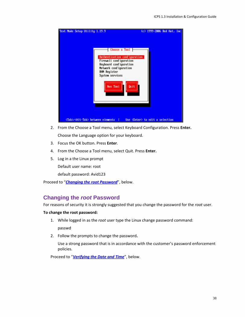
2. From the Choose a Tool menu, select Keyboard Configuration. Press Enter.
Choose the Language option for your keyboard.
3. Focus the OK button. Press Enter.
4. From the Choose a Tool menu, select Quit. Press Enter.
5. Log in a the Linux prompt
Default user name: root
default password: Avid123
Proceed to “Changing the root Password”, below.
Changing the root Password For reasons of security it is strongly suggested that you change the password for the root user.
To change the root password:
1. While logged in as the root user type the Linux change password command:
passwd
2. Follow the prompts to change the password.
Use a strong password that is in accordance with the customer’s password enforcement policies.
Proceed to “Verifying the Date and Time”, below.

ICPS 1.3 Installation & Configuration Guide
39
Verifying the Date and Time Although you set the time and date in the BIOS in an earlier step, it is worth verifying that it is still set correctly before proceeding. Linux takes ownership of the BIOS time and date setting, and may have altered it during the install.
To verify the date and time:
1. If you have not already done so log in.
Log in as the root user (i.e. username = root).
Note: The default root password is Avid123
2. To check the date type date and press enter.
The date is displayed.
3. If the date is incorrect, change it. For example, for September 2nd, 2012, at 11:03 a.m. enter:
date 090211032012
The required format is MMDDHHmmYYYY. (Month-Date-Hour-Minute-Year)
4. When you press enter the reset date is displayed:
Sun Sep 2 11:03:00 EDT 2012
Proceed to “Setting the Time Zone”, below.
Setting the Time Zone The installation script sets the location to Montreal and the time zone to Eastern Standard Time. Please customize your setup by setting the location more appropriately. In this step you edit the RHEL file that controls how the operating system interprets values in the system clock.
Note: This step requires the use of vi, the command-line text editor supplied with RHEL. For an introduction to vi, see “Working with Linux” on page 15.
To set the time zone:
1. Using Linux commands, list the contents of the directory containing RHEL time zone information:
ls /usr/share/zoneinfo
A list of time zone regions is presented. For example, US time zones are located under /usr/share/zoneinfo/US, European time zones are in /usr/share/zoneinfo/Europe, and so on.
2. Locate the time zone of interest in the subdirectories of /zoneinfo (e.g. US/Eastern) and take note of it for the next steps.
3. Using Linux commands, navigate to the directory containing the clock file read by RHEL at boot-time:
cd /etc/sysconfig
ICPS 1.3 Installation & Configuration Guide
40
4. List the contents of the directory:
ls -l
5. Using the Linux text editor vi, open the clock file for editing:
vi clock
6. Locate the ZONE information, and replace “America/Montreal” with the appropriate information, for example:
ZONE=”America/Los_Angeles”
Navigate using the arrow keys, then press A (append) and replace the information.
7. Save and exit the clock file by typing the following command from within the vi editing session:
<Esc>:wq
8. That is, tap the Escape key, then the colon, then type wq and press Return.
The file is saved and you are returned to the Linux prompt.
9. Create the symbolic link RHEL needs to make use of the new time zone information:
ln –sf /usr/share/zoneinfo/<yourzone> /etc/localtime
In the above command, <yourzone> is the path you entered in the clock file (e.g. America/Los_Angeles).
10. Verify the settings using the date command:
date
The local time and time zone should now be shown.
Proceed to “Editing the Network Connections” on page 40.
Editing the Network Connections
Under the Linux operating system, every physical network connector, called an interface in Linux, has a name. By default, when installing RHEL, the installer scans the NIC cards in the machine and labels the interfaces it finds, in the order it finds them. In this step, you verify that the interface you want ICS to use has the name eth0. If not, you rename the interface.
Note: This step requires the use of vi, the command-line text editor supplied with RHEL. For an introduction to vi, see “Working with Linux” on page 15.
The procedures in this section make use of the following information:
NIC cards present in the enclosure
NIC card used to connect the server to the network
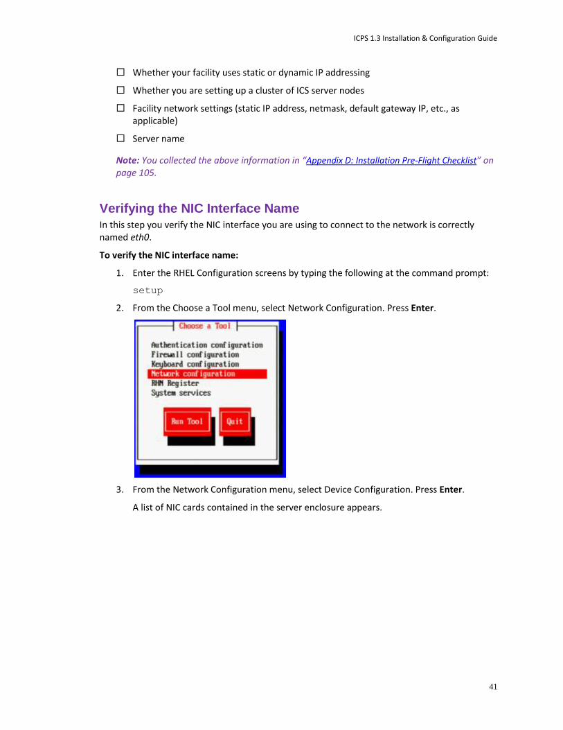
ICPS 1.3 Installation & Configuration Guide
41
Whether your facility uses static or dynamic IP addressing
Whether you are setting up a cluster of ICS server nodes
Facility network settings (static IP address, netmask, default gateway IP, etc., as applicable)
Server name
Note: You collected the above information in “Appendix D: Installation Pre-Flight Checklist” on page 105.
Verifying the NIC Interface Name
In this step you verify the NIC interface you are using to connect to the network is correctly named eth0.
To verify the NIC interface name:
1. Enter the RHEL Configuration screens by typing the following at the command prompt:
setup
2. From the Choose a Tool menu, select Network Configuration. Press Enter.
3. From the Network Configuration menu, select Device Configuration. Press Enter.
A list of NIC cards contained in the server enclosure appears.
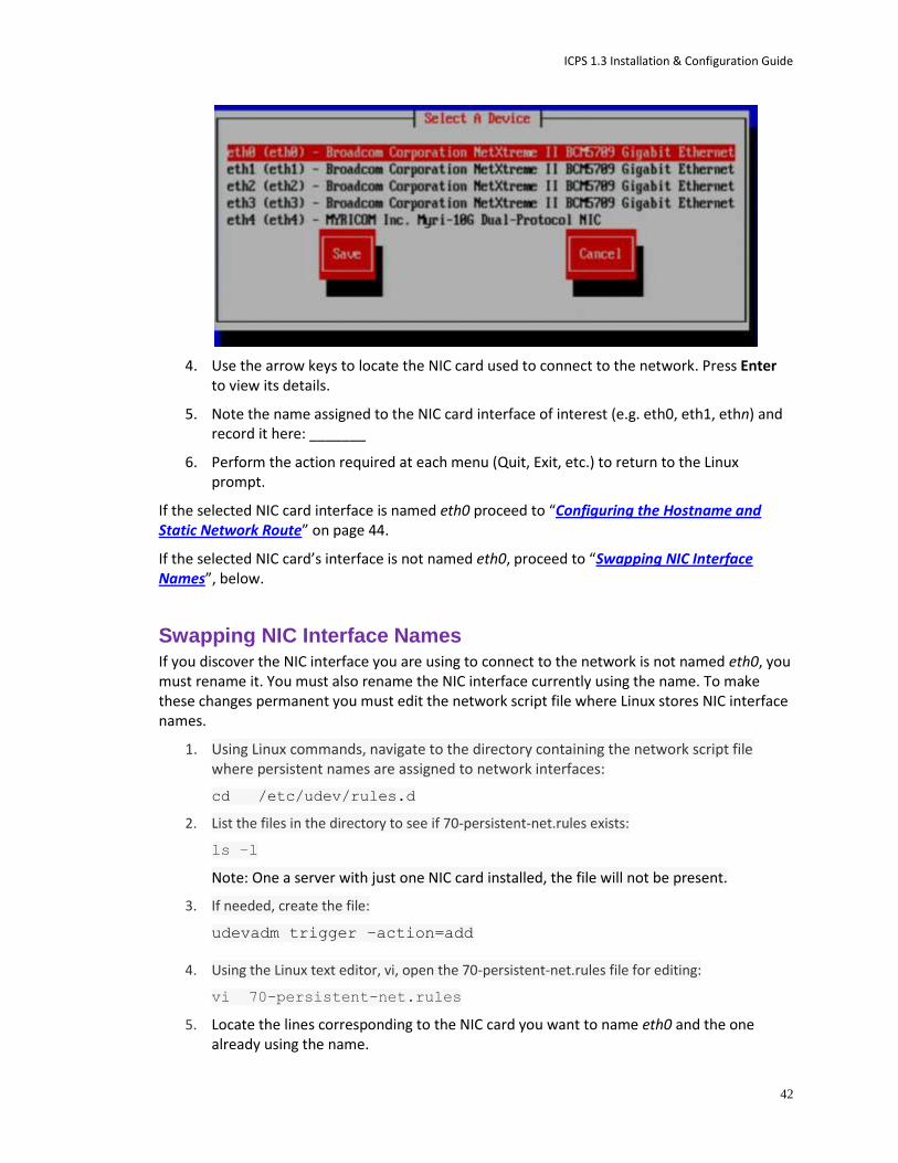
ICPS 1.3 Installation & Configuration Guide
42
4. Use the arrow keys to locate the NIC card used to connect to the network. Press Enter to view its details.
5. Note the name assigned to the NIC card interface of interest (e.g. eth0, eth1, ethn) and record it here: _______
6. Perform the action required at each menu (Quit, Exit, etc.) to return to the Linux prompt.
If the selected NIC card interface is named eth0 proceed to “Configuring the Hostname and Static Network Route” on page 44.
If the selected NIC card’s interface is not named eth0, proceed to “Swapping NIC Interface Names”, below.
Swapping NIC Interface Names If you discover the NIC interface you are using to connect to the network is not named eth0, you must rename it. You must also rename the NIC interface currently using the name. To make these changes permanent you must edit the network script file where Linux stores NIC interface names.
1. Using Linux commands, navigate to the directory containing the network script file where persistent names are assigned to network interfaces:
cd /etc/udev/rules.d
2. List the files in the directory to see if 70-persistent-net.rules exists:
ls –l
Note: One a server with just one NIC card installed, the file will not be present.
3. If needed, create the file:
udevadm trigger –action=add
4. Using the Linux text editor, vi, open the 70-persistent-net.rules file for editing:
vi 70-persistent-net.rules
5. Locate the lines corresponding to the NIC card you want to name eth0 and the one already using the name.

ICPS 1.3 Installation & Configuration Guide
43
Use the arrow keys on the keyboard to navigate the file.
6. Press the A key to append to the end of the line:
NAME="eth0"
7. Change NAME="ethX" (e.g. eth1, eth2, etc.) to the following:
NAME="eth0"
8. Locate the line corresponding to the NIC card that was already using the name eth0 and rename it:
NAME="ethX"
where “X” is the number you removed in step 5 (e.g. eth1, eth2, etc.); that is, swap the names.
9. Save and exit the 70-persistent-net.rules file by typing the following command from within the vi editing session:
<Esc>:wq
That is, tap the Escape key, then the colon, then type wq and press Return.
You are returned to the Linux prompt.
Proceed to “Removing the MAC Address Hardware References” below.
Removing the MAC Address Hardware References Even though you renamed a NIC interface to eth0 and made the changes permanent by editing the network script file, there is one more step. In this step you remove the hardware references – generally known as MAC addresses – from the affected NIC interface configuration files.
Recall that every NIC card is assigned a unique hardware identifier -- called a MAC address -- by the manufacturer. The MAC address uniquely identifies the NIC card hardware, and is permanently stored in the NIC card’s firmware. When Linux scans for NICs, it obtains this hardware identifier and writes it to an interface configuration file. Further, the Linux installation scripts create an interface configuration file (e.g. ifcfg-eth0, ifcfg-eth1, etc.) for each NIC interface found. For example, a NIC card with four network interfaces will have four interface configuration files.
For each card where you renamed a NIC interface, you must edit the corresponding interface configuration file -- that was already created by Linux -- and remove the hardware identifier. Otherwise, Linux will override the changes you made earlier and reassign the old interface names the next time it boots (or you restart the Linux network services).
To remove the hardware references from the interface configuration file:
Note: This procedure must be performed twice – once for each of the NIC interfaces you renamed.
1. Using Linux commands, navigate to the directory containing the network scripts files:
cd /etc/sysconfig/network-scripts
ICPS 1.3 Installation & Configuration Guide
44
2. List the contents of the directory:
ls –l
3. Using the Linux text editor, vi, open the interface configuration file for one of the renamed interfaces (e.g. ifcfg-eth0):
vi ifcfg-eth0
In Linux, each NIC interface has its own configuration file.
4. Locate the line containing the hardware identifier. It has the following form:
HWADDR = 00:00:00:00:00:00
In Linux, each NIC interface has its own configuration file.
5. Remove the whole line.
6. Save and exit the file by typing the following command from within the vi editing session:
<Esc>:wq
That is, tap the Escape key, then the colon, then type wq and press Return.
You are returned to the Linux prompt.
7. Repeat the above steps for the other NIC interface you renamed (e.g. ethX).
8. Once you have finished removing the hardware references for both the renamed NIC interfaces, reboot the server to restart the network services and make the effects permanent.
Proceed to “Configuring the Hostname and Static Network Route” below.
Configuring the Hostname and Static Network Route Now that the NIC interface you will use to connect the ICS server to the network has been named eth0, you are ready to configure the server to make the connection. This is done using the RHEL configuration facility.
This procedure make us of the facility network settings information you entered in “Appendix D: Installation Pre-Flight Checklist” on page 105.
To configure the hostname and static network route for eth0:
1. Enter the RHEL Configuration screens by typing the following at the command prompt:
setup
2. From the Choose a Tool menu, select Network Configuration. Press Enter.
3. From the Network Configuration menu, select Device Configuration. Press Enter.
A list of NIC cards contained in the server enclosure appears.
4. Use the arrow keys to locate the NIC card and interface named eth0. Press Enter to view its details

ICPS 1.3 Installation & Configuration Guide
45
5. Ensure the following information is correctly set:
Default name: eth0
Default device: eth0
DHCP is disabled (Spacebar to disable)
6. Disabling the Dynamic Host Configuration Protocol (DHCP) allows you to enter the following static network route information:
Facility Static IP address
Facility Netmask
Default Gateway IP
Primary DNS server
Secondary DNS server
7. Select OK. Press Enter.
You are returned to the list of NIC cards in the enclosure.
8. Select Save. Press Enter.
9. From the Choose a Tool Menu, select DNS Configuration. Press Enter.
10. Give the machine a name (host name) and enter its DNS information:
Enter the hostname: <machine name> (e.g. ics-dl360-1)
DNS entries should be carried over from step 6 (if you specified static IP addresses in that step).
If you are using a static IP addresses, enter the DNS search path domain
If you are using DHCP, leave the DNS search path domain blank.
Note: The host name indicated above is the host name only (e.g. ics-dl360-1),that is, the name of the machine. Do not use the fully qualified domain name (e.g. ics-dl360-1.mydomain.com or ics-dl360-1.mydomain.local).
11. Select Save & Quit. Press Enter.
12. Select Quit. Press Enter.
You may be prompted to login to the server.
Proceed to “Creating the File Cache on the RAID” on page 45.
Creating the File Cache on the RAID
In an earlier step you created a RAID 5 for the cache using the “arrays” utility built-in to the HP server’s BIOS. In this step you finalize caching. First, you partition the RAID. Next you create a logical volume for the RAID and mounting the ICS cache on it.
For a discussion of caching, see “Caching in ICS” on page 14.

ICPS 1.3 Installation & Configuration Guide
46
For a discussion of RAIDs, see “RAIDs in ICS” on page 20.
Partitioning the RAID In this procedure you partition the RAID and write the new partition table entry to disk using the Linux disk partitioning utility, fdisk.
To partition the RAID:
1. Use fdisk to ensure the Raid 5 HD device exists:
fdisk –l
A list of devices is displayed.
2. Find the entry corresponding to the RAID 5 device (/dev/sdb).
Note: The enclosure contains two devices of interest, the system disk (/dev/sda) and the RAID (/dev/sdb). Partitioning the system disk was performed automatically by the RHEL installer.
3. Instruct fdisk to begin operating on the RAID 5:
fdisk /dev/sdb
The fdisk command prompt appears:
Command (m for help):
4. Add a new partition:
a. Type n (lower case N) for new.
b. Type p (lower case P) for primary partition.
c. Type 1 for partition number 1 (one).
d. Default for first cylinder (Press Enter).
e. Default for last cylinder (Press Enter).
The fdisk utility creates the partition.
5. Write the new partition table to disk:
Command (m for help): W
The partition table is written and you are returned to the Linux prompt.
Creating the Logical Volume and Mounting the Cache In this procedure you work with the newly partitioned RAID 5 using the Linux Logical Volume Manager (LVM). The hierarchy of volumes in Linux is as follows: physical volume, volume group and logical volume.
To create the logical volume and mount the cache:
1. Create the physical volume:

ICPS 1.3 Installation & Configuration Guide
47
pvcreate --metadatasize=64k /dev/sdb1
LVM feedback indicates the successful creation of the physical volume.
2. Create a volume group, vg_ics_cache, containing the physical volume /dev/sdb1:
vgcreate -s 256K -M 2 vg_ics_cache /dev/sdb1
LVM feedback indicates the successful creation of the volume group.
3. Before creating the logical volume, obtain a value for the volume group’s physical extents:
vgdisplay vg_ics_cache
A list of properties for the volume groups appear, including the physical extents. Physical extents are the minimum amount by which a logical volume may be increased or decreased in size.
The value of interest is the one given for “Free PE / Size”. Use this value to create a logical volume occupying the entire volume group (below).
4. Create the logical volume, lv_ics_cache, containing the volume group vg_ics_cache:
lvcreate -l <Free_PEs> -r 1024 -n lv_ics_cache vg_ics_cache
In the above command, replace <Free_PEs> with the value obtained in the previous step. Note too that -l is a lower-case “L”.
For example:
lvcreate -l 4578332 -r 1024 -n lv_ics_cache vg_ics_cache
LVM feedback indicates the successful creation of the logical volume. Note that Linux may override the sector size you specified. That is OK.
5. Create a filesystem on the logical volume (i.e. format it):
mkfs.ext4 /dev/vg_ics_cache/lv_ics_cache
Note in the above command you specify logical volume by its Linux block device name (/dev/<volume_group>/<logical_volume>).
Feedback indicates success.
6. Navigate to the directory containing the filesystem table:
cd /etc
7. Open the filesystem table file, fstab, for editing:
vi fstab
8. Add an entry at the end of the file:
/dev/mapper/vg_ics_cache-lv_ics_cache /cache ext4 rw 0 0
ICPS 1.3 Installation & Configuration Guide
48
This automates the mapping of the logical volume to its proper folder (/cache in this case).
9. Save and exit the file by typing the following command from within the vi editing session:
<Esc>:wq
That is, tap the Escape key, then the colon, then type wq and press Return.
You are returned to the Linux prompt.
10. Mount the volume:
mount /cache
11. Verify that /cache has been mounted correctly:
df –h
The following information is displayed about the cache: size, used, available, user % and mount point (mounted on).
To set up a cluster of servers, proceed to “ Setting up the Server Cluster” on page 70.
Otherwise, proceed to one of the following:
“Installing the Interplay Central Distribution Service” on page 48.
“Configuring ICS for Interplay Central and/or Interplay Sphere” on page 50.
Installing the Interplay Central Distribution Service
The Interplay Central Distribution Service (ICDS) is an Interplay service that coordinates jobs with Avid Media Services for send to playback (STP). You can install it on a server that is already hosting an Interplay Production component (such as an Interplay Transcode server) or on a separate server in the Interplay Production workgroup.
You can install ICDS on two or more servers. Multiple ICDS servers provide a high-availability configuration and failover capability in case one server fails. For more information about ICDS, ICDS failover, and STP, see the Avid Interplay Central Administration Guide.
Determining Where to Install ICDS ICDS can be installed on any server currently configured in an Interplay Production workgroup except for servers hosting the following components:
Media Services Engine (port conflict, breaks editor functionality)
Interplay Engine (should not have Avid Service Framework installed)
Interplay Archive Engine (should not have Avid Service Framework installed)
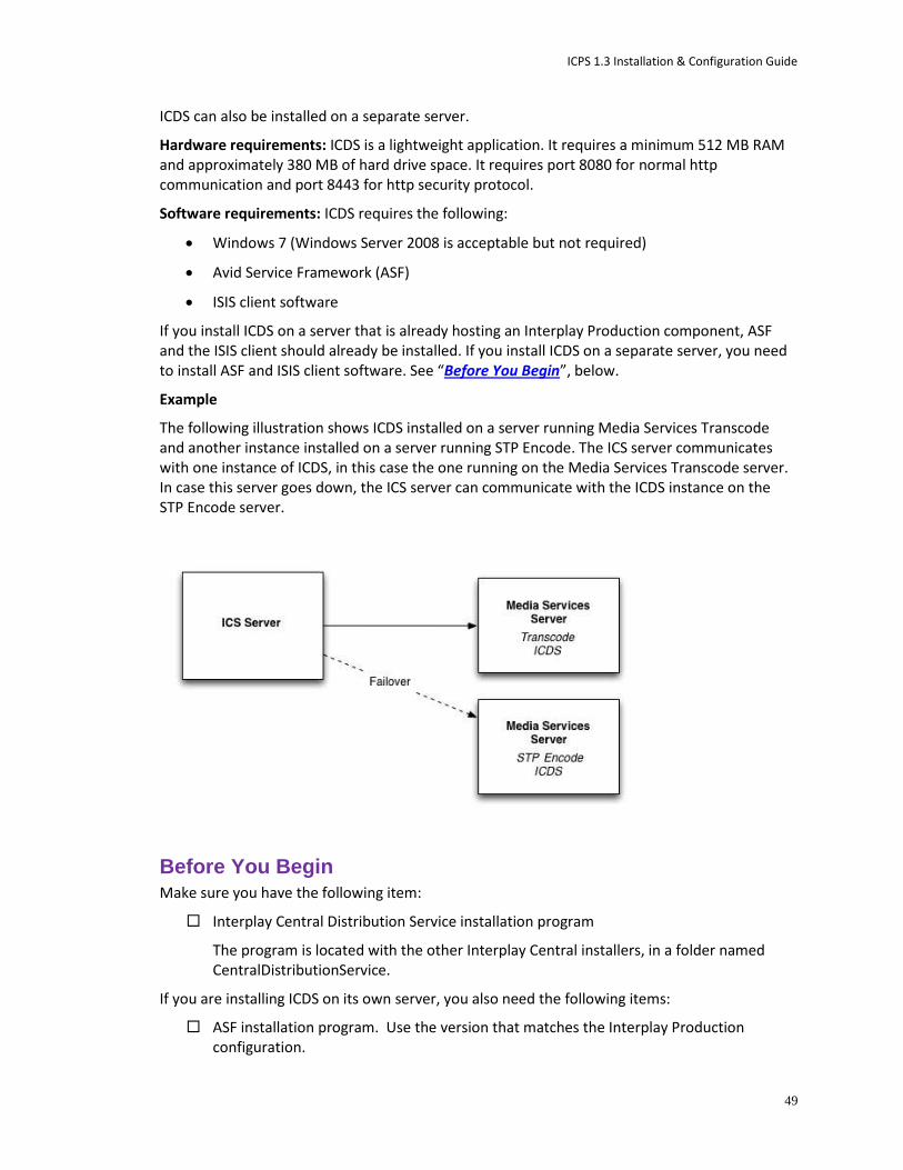
ICPS 1.3 Installation & Configuration Guide
49
ICDS can also be installed on a separate server.
Hardware requirements: ICDS is a lightweight application. It requires a minimum 512 MB RAM and approximately 380 MB of hard drive space. It requires port 8080 for normal http communication and port 8443 for http security protocol.
Software requirements: ICDS requires the following:
Windows 7 (Windows Server 2008 is acceptable but not required)
Avid Service Framework (ASF)
ISIS client software
If you install ICDS on a server that is already hosting an Interplay Production component, ASF and the ISIS client should already be installed. If you install ICDS on a separate server, you need to install ASF and ISIS client software. See “Before You Begin”, below.
Example
The following illustration shows ICDS installed on a server running Media Services Transcode and another instance installed on a server running STP Encode. The ICS server communicates with one instance of ICDS, in this case the one running on the Media Services Transcode server. In case this server goes down, the ICS server can communicate with the ICDS instance on the STP Encode server.
Before You Begin
Make sure you have the following item:
Interplay Central Distribution Service installation program
The program is located with the other Interplay Central installers, in a folder named CentralDistributionService.
If you are installing ICDS on its own server, you also need the following items:
ASF installation program. Use the version that matches the Interplay Production configuration.

ICPS 1.3 Installation & Configuration Guide
50
ICDS is a 32-bit application, so you can install either the 32-bit version of ASF or the 64-bit version (if the machine is a 64-bit machine). To ensure that a 32-bit application can see the 64-bit ASF, open the Workgroup Properties tool and connect to the Lookup service. See the Avid Interplay ReadMe for details.
Avid ISIS client installation program. Use the version that matches the Interplay Production configuration.
Configure access for the following:
Port 8080 for normal http communication and port 8443 for http security protocol
To install the Interplay Central Distribution Service:
1. If you are installing ICDS on its own server, install ASF and the Avid ISIS client software.
2. Copy the installer folder named CentralDistributionService to the server on which you are installing ICDS.
3. Open the installer folder and double-click setup.exe.
The welcome screen of the installer is displayed.
4. Click Next.
5. Accept the license agreement and click Next.
6. Accept the default installation location, or click Change to install to a different folder.
7. Click Next.
8. Click Install to begin the installation.
The installation should take only a few minutes.
9. When the installation is completed, click Finish.
The Interplay Central Distribution Service is automatically started as a Windows service.
Proceed to “Configuring ICS for Interplay Central and/or Interplay Sphere” on page 50.
Configuring ICS for Interplay Central and/or Interplay Sphere
Now that you have installed the operating system, ICS software components, and ICDS software (Interplay Central only), you are ready to configure the ICS server.
As an independent ISIS client, ICS has its own connection to ISIS, and uses a separate set of ISIS credentials to read media assets for playback and to write audio assets for voice-over recorded by Interplay Central end-users.
To configure ICS for Interplay Sphere you log into Interplay Central using a web browser.
Configuring ICS consists of:
1. Configuring the Interplay Central UI

ICPS 1.3 Installation & Configuration Guide
51
2. Logging into Interplay Central
3. Changing the Administrator Password
4. Configuring Interplay Production Settings
5. Configuring ICPS for Interplay
6. Configuring ICPS for Interplay Central
7. Configuring the ISIS Connection(s)
8. Mounting the ISIS System(s)
9. Verifying Video Playback
10. Configuring Wi-Fi Only Encoding for Facility-Based iOS Devices (optional)
11. Verifying Video Playback
Before You Begin Make sure you have the following items:
Windows XP/Vista/7 laptop or desktop computer
Network connection
Web browser supported by Interplay Central.
The procedures in this section make use of the following information:
Host name of the ICS server (e.g. ics-dl360-1)) or Static IP address of the ICS cluster (e.g.: 192.XXX.XXX.XXX)
New Interplay Central Administrator password.
Knowledge of whether or not MOS plug-ins are used (iNews workflows)
Interplay Workgroup name
Lookup server hostname(s)
Knowledge of whether multi-resolution workflows are being used
ISIS hostname(s)
ISIS user name and password reserved for ICS (e.g. ics-interplay)
Note: For multi-ISIS setups, ensure the same user credentials have been created for ICS across all ISIS storage systems.
Knowledge of the ICS connection(s):
o Zone 1 (direct connection)
o Zone 2 (via a network switch)
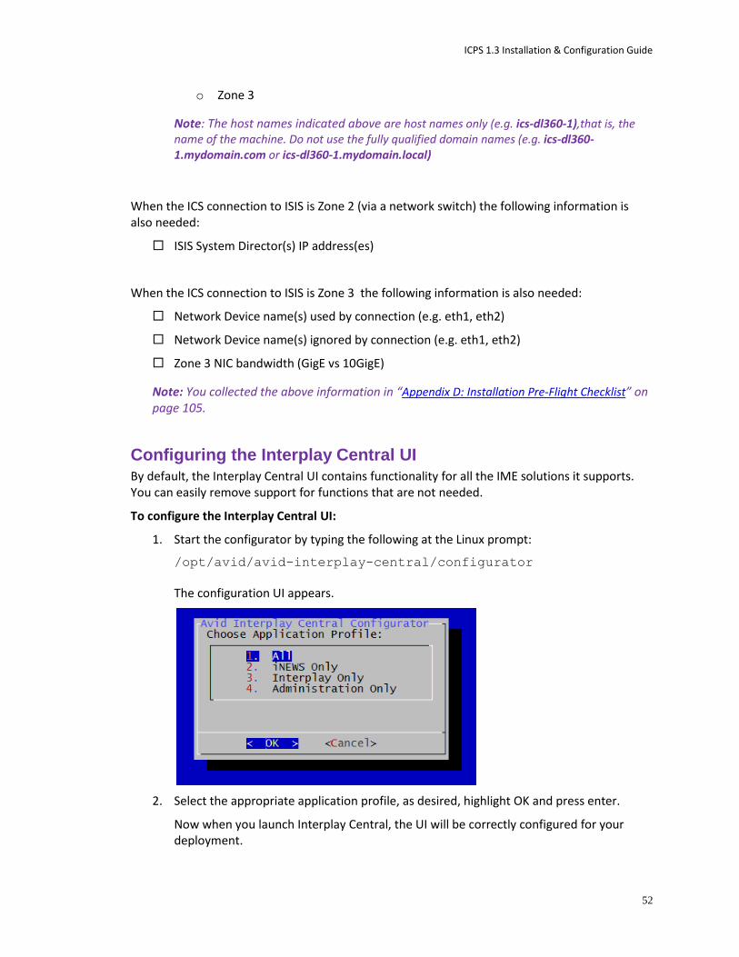
ICPS 1.3 Installation & Configuration Guide
52
o Zone 3
Note: The host names indicated above are host names only (e.g. ics-dl360-1),that is, the name of the machine. Do not use the fully qualified domain names (e.g. ics-dl360-1.mydomain.com or ics-dl360-1.mydomain.local)
When the ICS connection to ISIS is Zone 2 (via a network switch) the following information is also needed:
ISIS System Director(s) IP address(es)
When the ICS connection to ISIS is Zone 3 the following information is also needed:
Network Device name(s) used by connection (e.g. eth1, eth2)
Network Device name(s) ignored by connection (e.g. eth1, eth2)
Zone 3 NIC bandwidth (GigE vs 10GigE)
Note: You collected the above information in “Appendix D: Installation Pre-Flight Checklist” on page 105.
Configuring the Interplay Central UI By default, the Interplay Central UI contains functionality for all the IME solutions it supports. You can easily remove support for functions that are not needed.
To configure the Interplay Central UI:
1. Start the configurator by typing the following at the Linux prompt:
/opt/avid/avid-interplay-central/configurator
The configuration UI appears.
2. Select the appropriate application profile, as desired, highlight OK and press enter.
Now when you launch Interplay Central, the UI will be correctly configured for your deployment.

ICPS 1.3 Installation & Configuration Guide
53
Proceed to “Logging into Interplay Central”, below.
Logging into Interplay Central ICS servers are configured using the Interplay Central System Settings. You need access to the ICS server(s) you are configuring, and you need to launch a web browser. Before configuring Interplay Central or Interplay Sphere, you should change the ICS administrator’s account password.
This procedure makes use of the following information:
Interplay Central Administrator password.
Host name of the ICS server (e.g. ics-dl360-1)) or Static IP address of the ICS cluster (e.g.: 192.XXX.XXX.XXX)
To log into Interplay Central and change the administrator password:
1. Launch a web browser supported by Interplay Central.
For example, Google Chrome, IE (with Google Chrome Frame plug-in), or Safari (on Mac OS).
2. Enter the URL of the ICS server In the address bar:
Enter http://<hostname> where <hostname> is either the host name of the ICS server (if you only have a single server), or
Enter http://<cluster-IP> where <cluster-IP> is the IP address you provisioned for the ICS cluster
The Interplay Central sign-in screen appears.
(The first time you enter the URL, the EULA may appear instead.)
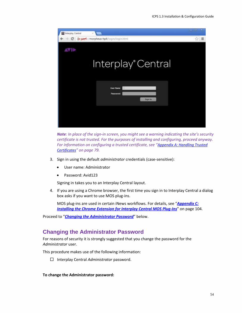
ICPS 1.3 Installation & Configuration Guide
54
Note: In place of the sign-in screen, you might see a warning indicating the site’s security certificate is not trusted. For the purposes of installing and configuring, proceed anyway. For information on configuring a trusted certificate, see “Appendix A: Handling Trusted
Certificates” on page 79.
3. Sign in using the default administrator credentials (case-sensitive):
User name: Administrator
Password: Avid123
Signing in takes you to an Interplay Central layout.
4. If you are using a Chrome browser, the first time you sign in to Interplay Central a dialog box asks if you want to use MOS plug-ins.
MOS plug-ins are used in certain iNews workflows. For details, see “Appendix C: Installing the Chrome Extension for Interplay Central MOS Plug-Ins” on page 104.
Proceed to “Changing the Administrator Password” below.
Changing the Administrator Password
For reasons of security it is strongly suggested that you change the password for the Administrator user.
This procedure makes use of the following information:
Interplay Central Administrator password.
To change the Administrator password:

ICPS 1.3 Installation & Configuration Guide
55
1. While logged in as the Administrator user, select Users from the Layout selector.
2. Expand the list of administrators in the User Tree and locate the Administrator user.
3. Double-click the Administrator user to view its details.
4. Click the Change Password button in the Details pane, and enter a new password for the Administrator user.
Use a strong password that is in accordance with the client’s password enforcement policies.
5. Click OK update the password information.
A message appears indicating that the password was successfully changed.
Proceed to “Configuring Interplay Production Settings” below.
Configuring Interplay Production Settings ICS communicates with Interplay Production directly. In this procedure you tell ICS which Interplay Production server it will use, and configure ICS with the user credentials and workgroup properties it needs to interact with Interplay Production.
Interplay Central and Interplay Sphere end-users log in with their own credentials and use their own Interplay credentials to browse media assets. However, ICS itself uses a separate set of Interplay credentials to resolve playback requests and check-in voice-over assets recorded by Interplay Central users.
This procedure makes use of the following information:
Interplay Production server (Interplay Engine) hostname
Interplay Central Distribution Service – Service URL (e.g. https://<server>:<port>)
Note: The host name indicated above is the host name only (e.g. ip-mtl-1),that is, it is the name of the machine. Do not use the fully qualified domain name (e.g. ip-mtl-1.mydomain.com or ip-mtl-1.mydomain.local). It can also be the IP address.

ICPS 1.3 Installation & Configuration Guide
56
To configure Interplay Production settings:
1. Select System Settings from the Layout selector.
2. In the Settings pane, click Interplay Production.
3. Configure Interplay Production credentials:
a. Enter the Interplay Production server (the Interplay engine) hostname or IP address.
b. Enter the Service URL of the Interplay Central Distribution Service (e.g https://<server>:<port>). You can enter a hostname or IP address for the server.
If your Interplay workgroup is configured for multiple ICDS servers, specify the multiple URLs separated by a comma and a space. The first server listed is the active ICDS server. Multiple ICDS servers provide a failover capability. For more information on failover for multiple ICDS servers, or other system settings, click the Pane Menu button and select Help or see the Avid Interplay Central Administration Guide.
4. Click Apply to save your changes.
Proceed to “Configuring ICPS for Interplay” below.
Configuring ICPS for Interplay Now that ICS can communicate with Interplay Production, you can configure the user name and password used by the Interplay Common Playback Service (ICPS) to log into the Interplay Production server. ICPS is one of the software services that runs on the ICS server. ICPS is responsible for the compression and playback of video and audio media on Internet-connected clients. It requires its own set of user credentials.
This procedure makes use of the following information:
Interplay Production user name and password reserved for ICS (e.g. ics-interplay). This needs to be created in the Interplay Production workgroup to which you are connecting.
Media Indexer host name
Interplay Workgroup name
Lookup server hostname(s)
Knowledge of whether multi-resolution workflows are being used
Note: The host names indicated above is the host name only (e.g. mi-mtl-1),that is, it is the name of the machine. Do not use the fully qualified domain name (e.g. mi-mtl-1.mydomain.com or mi-mtl-1.mydomain.local). It can also be the IP address.
To configure ICPS for Interplay:
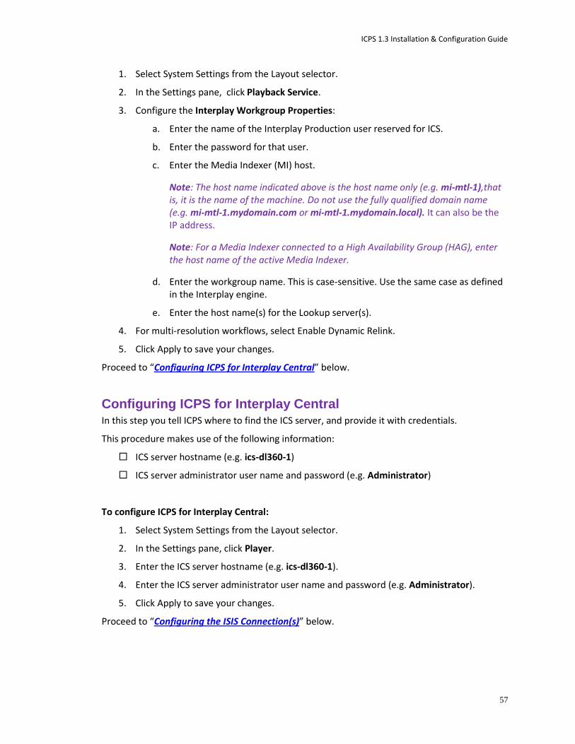
ICPS 1.3 Installation & Configuration Guide
57
1. Select System Settings from the Layout selector.
2. In the Settings pane, click Playback Service.
3. Configure the Interplay Workgroup Properties:
a. Enter the name of the Interplay Production user reserved for ICS.
b. Enter the password for that user.
c. Enter the Media Indexer (MI) host.
Note: The host name indicated above is the host name only (e.g. mi-mtl-1),that is, it is the name of the machine. Do not use the fully qualified domain name (e.g. mi-mtl-1.mydomain.com or mi-mtl-1.mydomain.local). It can also be the IP address.
Note: For a Media Indexer connected to a High Availability Group (HAG), enter the host name of the active Media Indexer.
d. Enter the workgroup name. This is case-sensitive. Use the same case as defined in the Interplay engine.
e. Enter the host name(s) for the Lookup server(s).
4. For multi-resolution workflows, select Enable Dynamic Relink.
5. Click Apply to save your changes.
Proceed to “Configuring ICPS for Interplay Central” below.
Configuring ICPS for Interplay Central In this step you tell ICPS where to find the ICS server, and provide it with credentials.
This procedure makes use of the following information:
ICS server hostname (e.g. ics-dl360-1)
ICS server administrator user name and password (e.g. Administrator)
To configure ICPS for Interplay Central:
1. Select System Settings from the Layout selector.
2. In the Settings pane, click Player.
3. Enter the ICS server hostname (e.g. ics-dl360-1).
4. Enter the ICS server administrator user name and password (e.g. Administrator).
5. Click Apply to save your changes.
Proceed to “Configuring the ISIS Connection(s)” below.
ICPS 1.3 Installation & Configuration Guide
58
Configuring the ISIS Connection(s) ICS is an ISIS client, maintaining its own connection to an ISIS system. Normally, only one active network connection is needed on the ICS server for this purpose. The single GigE or 10GigE connection functions for:
Communication with the ISIS
Playback of compressed media generated on the ICS server over the network
Multiple connections are possible. When you maintain other active connections on the ICS server, you must indicate which network connections are reserved for ISIS, and which are used for other network activity.
This procedure make use of the following information:
Knowledge of the ISIS connection(s):
o Zone 1 (direct connection)
o Zone 2 (layer 2 network switch)
o Zone 3 (layer 3 network switch)
Connection bandwidth (GigE vs 10GigE)
Name(s) of the NIC interfaces used to connect to ISIS (e.g. eth0)
Name(s) of the NIC interfaces used for other network activity
To configure the ISIS connection:
1. Select System Settings from the Layout selector.
2. In the Settings pane click Playback Service.
3. For a Zone 2 or Zone 3 connection, put a checkmark in Enable Remote Host.
For a Zone 1 connection leave Enable Remote Host unchecked.
4. Select the NIC interface bandwidth ( e.g. GigE, 10GigE).
5. For an ICS server with more than one active connection:
a. In the Use Network Device field, enter the network interface name(s) used to connect to the ISIS system, separated by commas.
b. In the Ignore Network Device field, enter the network interface name(s) to be ignored by ICS.
For an ICS server with only one active network connection (e.g. eth0) you can leave the fields blank.
6. Click Apply.
The information is sent to the ICS server, triggering a reconfiguration that may take a few moments.
Proceed to “Mounting the ISIS System(s)” below.

ICPS 1.3 Installation & Configuration Guide
59
Mounting the ISIS System(s) Now that you have specified what NIC interface connection(s) are used to reach the ISIS, you can mount the ISIS system(s). ICS communicates with ISIS storage directly. It uses a separate set of ISIS credentials from the end-user to read media assets for playback and to write audio assets for voice-over recorded by Interplay Central end-users.
In this procedure you configure ICS with the user credentials it needs to connect to the ISIS system(s). In some network configuration scenarios, additional settings are required.
This procedure make use of the following information:
ISIS Virtual Host Name(s)
ISIS user name and password reserved for ICS (e.g. ics-interplay)
Note: For multi-ISIS setups, ensure the same user credentials have been created for ICS across all ISIS storage systems.
Knowledge of the ICS connection(s) to the ISIS:
o Zone 1 (direct connection)
o Zone 2 or Zone 3 (via a network switch)
Note: The host name indicated above is the host name only (e.g. isis-mtl-1),that is, it is the name of the machine. Do not use the fully qualified domain name (e.g. isis-mtl-1.mydomain.com or isis-mtl-1.mydomain.local). It can also be the IP address.
When the ICS connection to the ISIS is Zone 2 (or higher) the following information is also needed:
ISIS System Director IP address(es)
To mount the ISIS system(s):
1. Select System Settings from the Layout selector.
2. In the Settings pane click Playback Service.
3. Click the plus (+ ) button to add the ISIS as a storage location.
A New File System dialog appears.
4. In the dialog, enter a nickname (label) to refer to the ISIS, indicate its type (ISIS), then click OK.
A new storage location is added to the list for the ISIS.
Since you have not yet configured ICS with user credentials for it, the status is disconnected.
5. Specify the necessary configuration details for the ISIS:
a. Virtual Host Name

ICPS 1.3 Installation & Configuration Guide
60
b. User name
c. Password
Note: The host name indicated above is the host name only (e.g. isis-mtl-1),that is, it is the name of the machine. Do not use the fully qualified domain name (e.g. isis-mtl-1.mydomain.com or isis-mtl-1.mydomain.local). It can also be the IP address.
6. For a Zone 2 or Zone 3 connection, enter list of IP addresses for the ISIS System Director. Separate each entry by a semi-colon.
Note: The interface suggests you separate the IP addresses using a comma, but a semi-colon must be used.
7. Click Apply.
The status changes to Connected.
8. Repeat the above for each additional ISIS (Zone 2 and Zone 3 only).
Proceed to “Verifying Video Playback” below.
Verifying Video Playback Playing some video is a simple technique for verifying that the configuration has had the desired effect.
To verify video playback:
1. Select Video from the Layout selector.
2. In the Launch pane select one of the mounted systems by double-clicking it.
3. Navigate the filesystem hierarchy and select a clip.
4. Double-click the clip to load it into the player.
5. Experiment with the player controls to play and scrub the clip.
Proceed to “Configuring Wi-Fi Only Encoding for Facility-Based iOS Devices” below (optional).
Or, proceed to “Clustering Workflow” on page 61 (optional).
Or, proceed to “Post-Installation Steps” on page 75.
ICPS 1.3 Installation & Configuration Guide
61
Configuring Wi-Fi Only Encoding for Facility-Based iOS Devices By default, ICS servers encode three different media streams for Interplay Central applications detected on iOS devices -- for Wi-Fi, 3G, and Edge connections. For Wi-Fi only facilities, it is recommended that you disable the 3G and Edge streams, to improve the encoding capacity of the ICS server.
To disable 3G and Edge streams:
1. Log in as root and edit the following file using a text editor (such as vi):
/usr/maxt/maxedit/share/MPEGPresets/MPEG2TS.mpegpresets
2. In each of the [Edge] and [3G] areas, set the active parameter to active=0.
3. Save and close the file.
Proceed to “Clustering Workflow” on page 61 (optional).
Or, proceed to “Post-Installation Steps” on page 75.
Clustering Workflow
Clustering requires that you set up one server completely before creating a cluster. That is, set up ICS on a server as if you were performing a non-clustered installation. Once that is done, you can set up the other ICS servers and add them to the cluster.
The following table outlines the clustering installation workflow:
Step Task Time Est.
1 Setting up and Configuring a Single ICS Server 2–3 hr
Perform all the steps to set up a fully operational ICS server.
This includes establishing the network and storage connections, setting up the RAID 1 and RAID 5 (if required), installing RHEL and ICS, ICDS (Interplay Central only), etc.
Importantly, it also includes all the configuration steps for the IME solution of choice (Interplay Central, Interplay Sphere).
2 Installing RHEL and ICS on the Other Servers in the Cluster 1 hr
Perform the same setup and installation steps outlined above, with the exception of configuring the server for the IME solution. These other servers in the cluster will inherit the settings of the master server, once they are added to the cluster.
You do not need to configure the other ICS servers in the cluster. That is, you do not need to configure the Interplay Production settings, configure ICPS for Interplay, Interplay Central, etc.
3 Replicating the Cluster File Caches 20 min
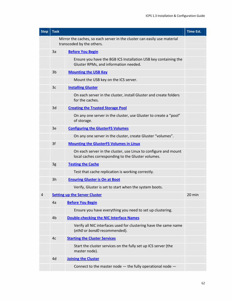
ICPS 1.3 Installation & Configuration Guide
62
Step Task Time Est.
Mirror the caches, so each server in the cluster can easily use material transcoded by the others.
3a Before You Begin
Ensure you have the 8GB ICS Installation USB key containing the Gluster RPMs, and information needed.
3b Mounting the USB Key
Mount the USB key on the ICS server.
3c Installing Gluster
On each server in the cluster, install Gluster and create folders for the caches.
3d Creating the Trusted Storage Pool
On any one server in the cluster, use Gluster to create a “pool” of storage.
3e Configuring the GlusterFS Volumes
On any one server in the cluster, create Gluster “volumes”.
3f Mounting the GlusterFS Volumes in Linux
On each server in the cluster, use Linux to configure and mount local caches corresponding to the Gluster volumes.
3g Testing the Cache
Test that cache replication is working correctly.
3h Ensuring Gluster is On at Boot
Verify, Gluster is set to start when the system boots.
4 Setting up the Server Cluster 20 min
4a Before You Begin
Ensure you have everything you need to set up clustering.
4b Double-checking the NIC Interface Names
Verify all NIC interfaces used for clustering have the same name (eth0 or bond0 recommended).
4c Starting the Cluster Services
Start the cluster services on the fully set up ICS server (the master node).
4d Joining the Cluster
Connect to the master node — the fully operational node —

ICPS 1.3 Installation & Configuration Guide
63
Step Task Time Est.
from the other ICS nodes.
5 Post-Installation Steps 5 min
Verify the cluster is working and intended.
Proceed to “Replicating the Cluster File Caches” on page 63.
Replicating the Cluster File Caches
Before you set up a server cluster you should enable the automatic replication of cluster file caches between all servers. This is done using Gluster, an open source software solution for creating shared filesystems. In ICS it is used to automate replication of the RAID 5 file caches across all ICS servers in the cluster.
Recall that the ICS server transcodes media from the format in which it is stored on the ISIS (or Standard FS storage) into an alternate delivery format. Further, in certain deployments you are required to set up a RAID 5 volume where ICS caches these temporary files:
Interplay Central installations deploying the iNews iOS (Apple mobile operating system) app require a RAID 5 cache volume. In this case, media on the ISIS are transcoded to MPEG-TS (MPEG-2 transport stream) and stored.
In a deployment with a single ICS server, the ICS server maintains a cache where it stores recently-transcoded media. In the event that the same media is requested again, the ICS server can deliver the cached media, without the need to re-transcode it. In a cluster, the contents of the RAID 5 volumes are replicated across all the nodes, giving each server access to all the transcoded media.
Note: The correct functioning of cache replication requires that the clocks on each server in the cluster are set to the same time. This was performed in “Setting the System Clock and Disabling HP Power Saving Mode” on page 31.
Before You Begin
The procedures in this section require the following:
The 8GB ICS Installation USB key containing the Gluster RPMs
If you did not prepare the USB key, return to “Copying Gluster to the USB Key” on page 29 before continuing.
The procedures in this section make us of the following information you entered in “Appendix D: Installation Pre-Flight Checklist” on page 105:
Machine name (host name) of each server in the cluster (e.g. ics-dl360-1, ics-dl380-1)
Note: The host name indicated above is the host name only (e.g. ics-dl360-1),that is, it is the name of the machine. Do not use the fully qualified domain name

ICPS 1.3 Installation & Configuration Guide
64
(e.g. ics-dl360-1.mydomain.com or ics-dl360-1.mydomain.local). It can also be the IP address.
Proceed to “Mounting the USB Key” below.
Mounting the USB Key Before you can gain access to the Gluster RPM files on the ICS Installation USB key, you must mount the USB key on the ICS server where they will be installed. Mounting is a Linux operation that makes a device available to the Linux operating system. In Linux, all hardware devices (USB keys, CD drives, HDs) must be mounted before they can be used.
To mount the USB key as a device:
1. On each server in the cluster, Insert the USB key into the ICS server.
Note: Advanced Linux users may prefer to mount the USB key as a network share to install the Gluster components on each server more easily.
2. Verify the name of the device using the dmesg command:
dmesg
Linux information relating to hardware appears on the screen.
Information for the USB key will appear in the output, near the list of SCSI devices. The name of the USB key is found inside square brackets (e.g. sdc). This is the name you use to mount the key.
3. Create a mount point for the USB key:
mkdir /media/usb
4. Mount the USB key at the mount point you just created:
mount /dev/sdc1 /media/usb
Note the name of the USB key, sdc (in this case), takes a 1 (one) in the mount command. This simply indicates a partition exists on the USB key. Formatting the USB key in Windows, earlier, created the partition.
The USB key is now mounted and available for use.
To unmount the USB key:
Before you move the USB key to another server, it is good practice to unmount it, freeing the associated resources.
1. Unmount the USB key:
umount /dev/sdc1 /media/usb
The USB key is now available for use in another server.

ICPS 1.3 Installation & Configuration Guide
65
Proceed to “Installing Gluster” below.
Installing Gluster Once the ICS Installation USB key is mounted on the Linux server, you can install Gluster. In this step, you both install the Gluster RPMs and create the folders where the caches will be located.
To install the software and create the cache folders:
1. On each server in the cluster, install the Gluster packages using the Linux rpm command. Install them in the following order:
rpm -Uvh /media/usb/Gluster/glusterfs-3.3.1-1.el6.x86_64.rpm
rpm -Uvh /media/usb/Gluster/glusterfs‐fuse‐3.3.1‐1.el6.x86_64.rpm
rpm –Uvh /media/usb/Gluster/glusterfs‐server‐3.3.1‐1.el6.x86_64.rpm
rpm -Uvh /media/usb/Gluster/glusterfs‐geo‐replication‐3.3.1‐1.el6.x86_64.rpm
2. Ensure Gluster daemon, glusterd, is running:
service glusterd status
3. If not, start it:
service glusterd start
2. Create the physical folders where the original data will reside:
mkdir -p /cache/gluster/gluster_data_download
mkdir -p /cache/gluster/gluster_data_fl_cache
mkdir -p /cache/gluster/gluster_data_metadata
Proceed to “Creating the Trusted Storage Pool” below.
Creating the Trusted Storage Pool With Gluster installed and running on each ICS server in the cluster, you can create the trusted storage pool. This is done by using the probe command:
gluster peer probe <hostname>
The command adds <hostname> to the trusted storage pool. It must be issued once for each server in the cluster, though not for the one from which it is being issued.
Example
To illustrate the command, consider an ICS server cluster consisting of three servers, ics-dl360-1, ics-dl360-2 and ics-dl360-3.
To create the GlusterFS trusted storage pool from ics-dl360-1, you would issue the following commands:
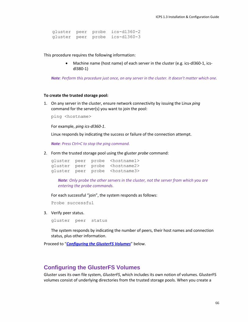
ICPS 1.3 Installation & Configuration Guide
66
gluster peer probe ics-dl360-2
gluster peer probe ics-dl360-3
This procedure requires the following information:
Machine name (host name) of each server in the cluster (e.g. ics-dl360-1, ics-dl380-1)
Note: Perform this procedure just once, on any server in the cluster. It doesn’t matter which one.
To create the trusted storage pool:
1. On any server in the cluster, ensure network connectivity by issuing the Linux ping command for the server(s) you want to join the pool:
ping <hostname>
For example, ping ics-dl360-1.
Linux responds by indicating the success or failure of the connection attempt.
Note: Press Ctrl+C to stop the ping command.
2. Form the trusted storage pool using the gluster probe command:
gluster peer probe <hostname1>
gluster peer probe <hostname2>
gluster peer probe <hostname3>
Note: Only probe the other servers in the cluster, not the server from which you are entering the probe commands.
For each successful “join”, the system responds as follows:
Probe successful
3. Verify peer status.
gluster peer status
The system responds by indicating the number of peers, their host names and connection status, plus other information.
Proceed to “Configuring the GlusterFS Volumes” below.
Configuring the GlusterFS Volumes Gluster uses its own file system, GlusterFS, which includes its own notion of volumes. GlusterFS volumes consist of underlying directories from the trusted storage pools. When you create a
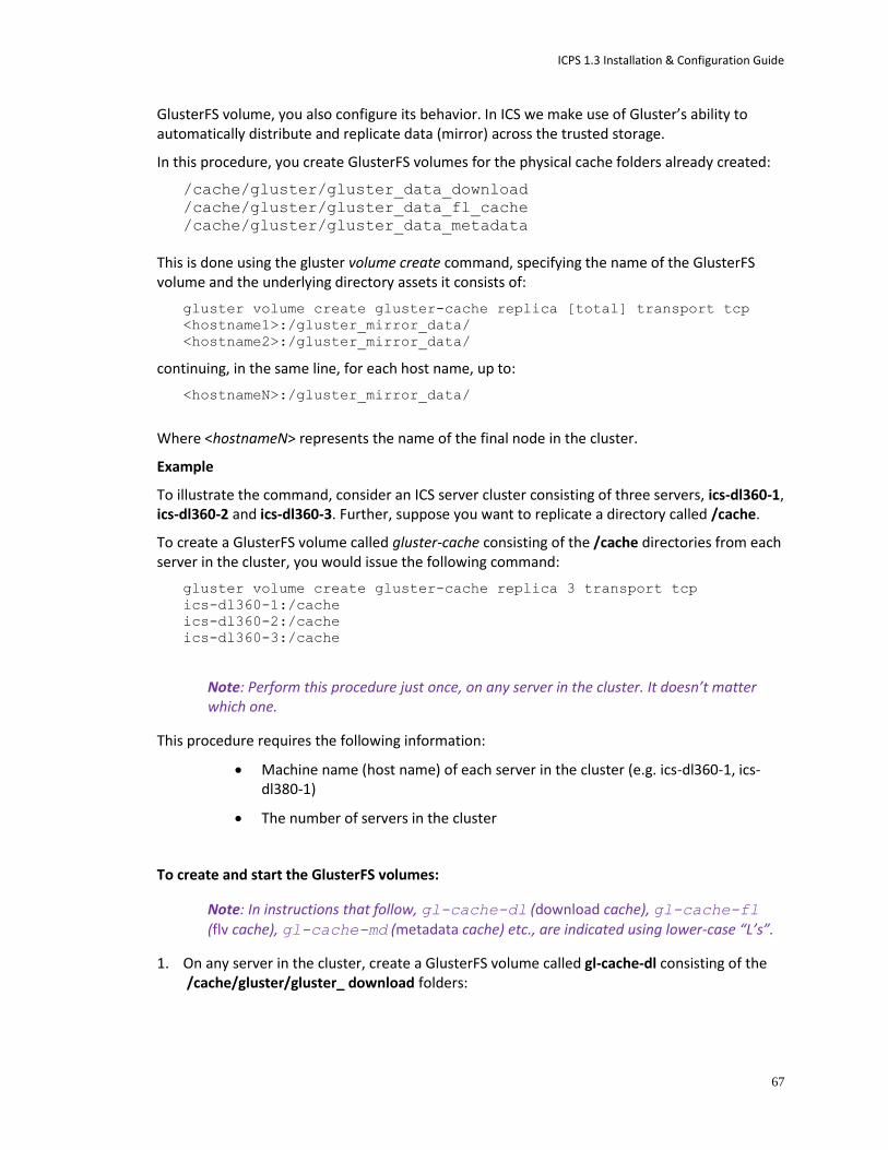
ICPS 1.3 Installation & Configuration Guide
67
GlusterFS volume, you also configure its behavior. In ICS we make use of Gluster’s ability to automatically distribute and replicate data (mirror) across the trusted storage.
In this procedure, you create GlusterFS volumes for the physical cache folders already created:
/cache/gluster/gluster_data_download
/cache/gluster/gluster_data_fl_cache
/cache/gluster/gluster_data_metadata
This is done using the gluster volume create command, specifying the name of the GlusterFS volume and the underlying directory assets it consists of:
gluster volume create gluster-cache replica [total] transport tcp
<hostname1>:/gluster_mirror_data/
<hostname2>:/gluster_mirror_data/
continuing, in the same line, for each host name, up to:
<hostnameN>:/gluster_mirror_data/
Where <hostnameN> represents the name of the final node in the cluster.
Example
To illustrate the command, consider an ICS server cluster consisting of three servers, ics-dl360-1, ics-dl360-2 and ics-dl360-3. Further, suppose you want to replicate a directory called /cache.
To create a GlusterFS volume called gluster-cache consisting of the /cache directories from each server in the cluster, you would issue the following command:
gluster volume create gluster-cache replica 3 transport tcp
ics-dl360-1:/cache
ics-dl360-2:/cache
ics-dl360-3:/cache
Note: Perform this procedure just once, on any server in the cluster. It doesn’t matter which one.
This procedure requires the following information:
Machine name (host name) of each server in the cluster (e.g. ics-dl360-1, ics-dl380-1)
The number of servers in the cluster
To create and start the GlusterFS volumes:
Note: In instructions that follow, gl-cache-dl (download cache), gl-cache-fl (flv cache), gl-cache-md (metadata cache) etc., are indicated using lower-case “L’s”.
1. On any server in the cluster, create a GlusterFS volume called gl-cache-dl consisting of the /cache/gluster/gluster_ download folders:

ICPS 1.3 Installation & Configuration Guide
68
gluster volume create gl-cache-dl replica <N> transport tcp
<hostname1>:/cache/gluster/gluster_data_download
<hostname2>:/cache/gluster/gluster_data_download
continuing, in the same line, for each host name, up to:
<hostnameN>:/cache/gluster/gluster_data_download
Where <hostname1> through <hostnameN> are the machine names (host names) of the servers in the cluster.
2. Create a GlusterFS volume called gl-cache-fl consisting of the /cache/gluster/gluster_data_fl_cache folders:
gluster volume create gl-cache-fl replica <N> transport tcp
<hostname1>:/cache/gluster/gluster_data_fl_cache
<hostname2>:/cache/gluster/gluster_data_fl_cache
continuing, in the same line, for each host name, up to:
<hostnameN>:/cache/gluster/gluster_data_fl_cache
3. Create a GlusterFS volume called gl-cache-md consisting of the /cache/gluster/gluster_data_metadata folders:
gluster volume create gl-cache-md replica <N> transport tcp
<hostname1>:/cache/gluster/gluster_data_metadata
<hostname2>:/cache/gluster/gluster_data_metadata
continuing, in the same line, for each host name, up to:
<hostnameN>:/cache/gluster/gluster_data_metadata
4. Start the GlusterFS volumes.
This step only needs to be done once, on the server where the GlusterFS volume was created:
gluster volume start gl-cache-dl
gluster volume start gl-cache-fl
gluster volume start gl-cache-md
Proceed to “Mounting the GlusterFS Volumes in Linux” below.
Mounting the GlusterFS Volumes in Linux With the GlusterFS volumes now created and Gluster service running, you can configure the local cache on each server in the cluster.
To mount the GlusterFS volumes in Linux:
1. On each server in the cluster create the following cache folders:
mkdir /cache/download
mkdir /cache/fl_cache

ICPS 1.3 Installation & Configuration Guide
69
mkdir /cache/metadata
Note: If you are creating a cluster for a system that has already been set up and run, the above folders already exist.
2. Give the maxmin:maxmin user access to the following two folders (original data folders, not the cache folders created above):
chown maxmin:maxmin /cache/gluster/gluster_data_download
chown maxmin:maxmin /cache/gluster/gluster_data_fl_cache
Note: There is no need to change ownership of the metadata folder.
Note: If you are creating a cluster for a system that has already been set up and run, the owner has already been changed.
3. Mount the folders using the Linux mount command, specifying the type as glusterfs:
mount -t glusterfs <hostname>:/gl-cache-dl /cache/download
mount -t glusterfs <hostname>:/gl-cache-fl /cache/fl_cache
mount -t glusterfs <hostname>:/gl-cache-md /cache/metadata
Where <hostname> is the name of the server you are working on (e.g. ics-dl360-1).
5. Navigate to the directory containing the filesystem table:
cd /etc
6. Open the filesystem table file, fstab, for editing:
vi fstab
7. Navigate to the end of the file and add the following three lines (A to append):
<hostname>:/gl-cache-dl /cache/download glusterfs defaults 0 0
<hostname>:/gl-cache-fl /cache/fl_cache glusterfs defaults 0 0
<hostname>:/gl-cache-md /cache/metadata glusterfs defaults 0 0
Where <hostname> is the name of the server you are working on (e.g. ics-dl360-1). Note the cache names use lower-case “L’s”.
These lines automate the mounting of the GlusterFS volumes to the folders used by ICS for caching (/cache/download, /cache/fl_cache and /cache/metadata).
8. Save and exit the file by typing the following command from within the vi editing session:
<Esc>:wq
That is, tap the Escape key, then the colon, then type wq and press Return.
9. Verify that caches have been mounted correctly:
df –h
The following information is displayed about the caches: size, used, available, user % and mount point (mounted on).
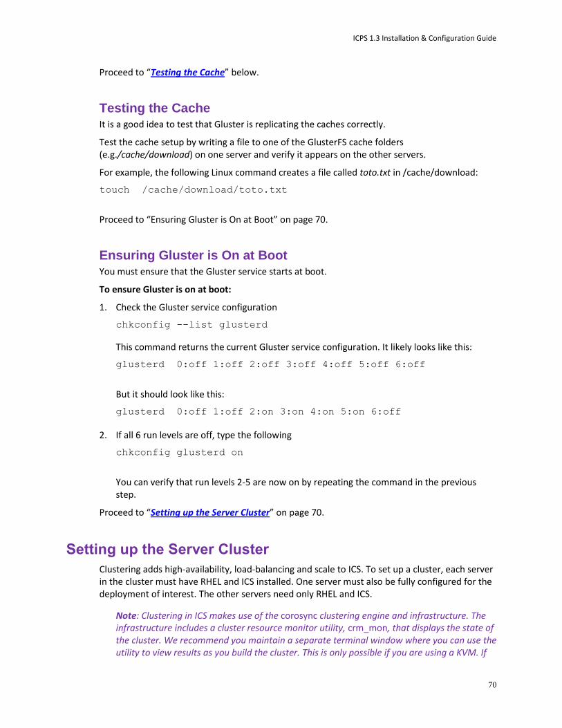
ICPS 1.3 Installation & Configuration Guide
70
Proceed to “Testing the Cache” below.
Testing the Cache It is a good idea to test that Gluster is replicating the caches correctly.
Test the cache setup by writing a file to one of the GlusterFS cache folders (e.g./cache/download) on one server and verify it appears on the other servers.
For example, the following Linux command creates a file called toto.txt in /cache/download:
touch /cache/download/toto.txt
Proceed to “Ensuring Gluster is On at Boot” on page 70.
Ensuring Gluster is On at Boot You must ensure that the Gluster service starts at boot.
To ensure Gluster is on at boot:
1. Check the Gluster service configuration
chkconfig --list glusterd
This command returns the current Gluster service configuration. It likely looks like this:
glusterd 0:off 1:off 2:off 3:off 4:off 5:off 6:off
But it should look like this:
glusterd 0:off 1:off 2:on 3:on 4:on 5:on 6:off
2. If all 6 run levels are off, type the following
chkconfig glusterd on
You can verify that run levels 2-5 are now on by repeating the command in the previous step.
Proceed to “Setting up the Server Cluster” on page 70.
Setting up the Server Cluster
Clustering adds high-availability, load-balancing and scale to ICS. To set up a cluster, each server in the cluster must have RHEL and ICS installed. One server must also be fully configured for the deployment of interest. The other servers need only RHEL and ICS.
Note: Clustering in ICS makes use of the corosync clustering engine and infrastructure. The infrastructure includes a cluster resource monitor utility, crm_mon, that displays the state of the cluster. We recommend you maintain a separate terminal window where you can use the utility to view results as you build the cluster. This is only possible if you are using a KVM. If
ICPS 1.3 Installation & Configuration Guide
71
you are working from a terminal attached directly to the server, simply run crm_mon periodically to view the results of your clustering operations.
The procedures in this step make use of the following information you entered in “Appendix D: Installation Pre-Flight Checklist” on page 105:
The static IP address allocated for the cluster
IP address that is always available (e.g. network router)
Email addresses of network administrators
Before You Begin Before you begin, make sure of the following:
RHEL and ICS software components are installed on all servers in the cluster
All servers are on the network and are assigned IP addresses
You have an assigned cluster IP address (distinct from the servers in the cluster)
If your network already uses multicast, IT must issue you a multicast address to avoid potential conflicts. If your network does not use multicast, the cluster can safely use a default multicast address.
Double-checking the NIC Interface Names
Every server in the cluster must connect to the network via a NIC interface named eth0. This may not be the case, by default, for a number of reasons, including systems with multiple network interface cards, re-assignment due to matches in network rules files, or explicit settings in the NIC’s configuration file.
Although you explicitly set the NIC interface names immediately after booting Linux for the first time, follow this procedure to double-check they are still correct.
To double-check the NIC interface names:
1. On all servers in the cluster, use Linux commands to navigate to the directory containing the network script file where persistent names are assigned to network interfaces:
cd /etc/udev/rules.d
2. List the files in the directory to see if 70-persistent-net.rules exists:
ls -l
Note: On a server with just one NIC card installed, the file may not exist.
3. If the file does not exist, create it using the following command:
udevadm trigger --action=add
4. Using the Linux text editor, vi, open the 70-persistent-net.rules file for editing:

ICPS 1.3 Installation & Configuration Guide
72
vi 70-persistent-net.rules
5. Locate the entry for the NIC interface used for clustering, and verify it is named correctly (eth0):
# PCI device 0x14e4:0x1639 (model)
SUBSYSTEM=="net", ACTION=="add", DRIVERS=="?*",
ATTR{address}=="9c:8e:99:1b:31:d4", ATTR{type}=="1",
KERNEL=="eth*", NAME="eth0"
model is the NIC model name provided by the manufacturer.
NAME="eth0" assigns the named (i.e. matched) NIC to the physical port eth0. This same port must be used for each NIC in the cluster.
6. Similarly, examine the contents of the NIC interface’s configuration file. Navigate to the directory:
cd /etc/sysconfig/network-scripts
7. Using the Linux text editor, vi, open the interface configuration file for editing:
vi ifcfg-eth0
8. The file should look something like this:
DEVICE=eth0
HWADDR=9c:8e:99:1b:31:d4
NM_CONTROLLED=yes
ONBOOT=yes
DHCP_HOSTNAME=$HOSTNAME
BOOTPROTO=static
TYPE=Ethernet
USERCTL=no
PEERDNS=yes
IPV6INIT=no
DEVICE=eth0 specifies the name of the physical Ethernet interface device.
ONBOOT=yes instructs the OS to bring up the device at boot time. Must be yes.
BOOTPROTO=static
IPADDR and NETMASK entries will also be present.
9. If there are other NIC cards installed in the enclosure, verify their interface configuration files to ensure there are no naming conflicts. For example, verify that the value assigned to DEVICE is different for each one.
If the settings examined here are correct, proceed to “Starting the Cluster Services”, below.
Otherwise, you need to fix the network settings before continuing. Proceed to “Editing the Network Connections” on page 40.
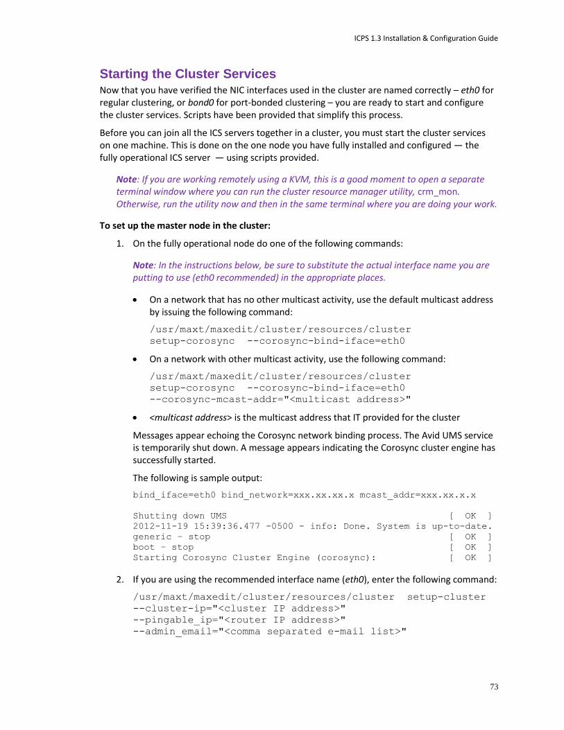
ICPS 1.3 Installation & Configuration Guide
73
Starting the Cluster Services Now that you have verified the NIC interfaces used in the cluster are named correctly – eth0 for regular clustering, or bond0 for port-bonded clustering – you are ready to start and configure the cluster services. Scripts have been provided that simplify this process.
Before you can join all the ICS servers together in a cluster, you must start the cluster services on one machine. This is done on the one node you have fully installed and configured — the fully operational ICS server — using scripts provided.
Note: If you are working remotely using a KVM, this is a good moment to open a separate terminal window where you can run the cluster resource manager utility, crm_mon. Otherwise, run the utility now and then in the same terminal where you are doing your work.
To set up the master node in the cluster:
1. On the fully operational node do one of the following commands:
Note: In the instructions below, be sure to substitute the actual interface name you are putting to use (eth0 recommended) in the appropriate places.
On a network that has no other multicast activity, use the default multicast address by issuing the following command:
/usr/maxt/maxedit/cluster/resources/cluster
setup-corosync --corosync-bind-iface=eth0
On a network with other multicast activity, use the following command:
/usr/maxt/maxedit/cluster/resources/cluster
setup-corosync --corosync-bind-iface=eth0
--corosync-mcast-addr="<multicast address>"
<multicast address> is the multicast address that IT provided for the cluster
Messages appear echoing the Corosync network binding process. The Avid UMS service is temporarily shut down. A message appears indicating the Corosync cluster engine has successfully started.
The following is sample output:
bind_iface=eth0 bind_network=xxx.xx.xx.x mcast_addr=xxx.xx.x.x
Shutting down UMS [ OK ]
2012-11-19 15:39:36.477 -0500 - info: Done. System is up-to-date.
generic – stop [ OK ]
boot – stop [ OK ]
Starting Corosync Cluster Engine (corosync): [ OK ]
2. If you are using the recommended interface name (eth0), enter the following command:
/usr/maxt/maxedit/cluster/resources/cluster setup-cluster
--cluster-ip="<cluster IP address>"
--pingable_ip="<router IP address>"
--admin_email="<comma separated e-mail list>"
ICPS 1.3 Installation & Configuration Guide
74
<cluster IP address> is the IP address provided by IT for the cluster (e.g.: 192.XXX.XXX.XXX)
<router IP address> is an IP address that will always be available on the network -- for example, the IP address of a network router
<comma separated e-mail list> is a comma separated list of e-mail addresses to which cluster status notifications are automatically sent
3. Otherwise, if you are not using the recommended interface name, enter the following command instead:
/usr/maxt/maxedit/cluster/resources/cluster setup-cluster
--cluster-ip="<cluster IP address>"
--pingable_ip="<router IP address>"
--cluster_ip_iface="<interface_name>"
--admin_email="<comma separated e-mail list>"
<interface_name> is the name of the NIC interface being used by the cluster (shown in bold above).
4. Error messages appear indicating missing resources and attributes.
For example:
ERROR: resource <resource name> does not exist
Error: performing operation: The object/attribute does not exist
These can be ignored.
5. Warning, error and info messages may also appear, similar to the following:
WARNING: 125: AvidConnectivityMon: specified timeout 20s for
start is smaller than the advised 60
ERROR: 125: rsc-options: attribute admin-email does not exist
INFO: 125: commit forced
These can be ignored.
6. Finally, the cluster configuration file is output to screen.
It identifies the node name, and various internal configuration information.
7. You can view the contents of the configuration file, at any time, by typing:
crm configure show
8. If necessary, press Q to get back to the Linux command line prompt.
9. Now that the clustering services are up and running on the master node, start the cluster monitoring tool to view progress as you add the other nodes to the cluster:
crm_mon
Joining the Cluster With the clustering services up and running on the master node – the fully configured ICS server – add the other servers to the cluster.
ICPS 1.3 Installation & Configuration Guide
75
To add other servers to the cluster:
On each of the non-master servers in the cluster, do one of the following commands:
Note: In the instructions below, be sure to substitute the actual interface name you are putting to use (eth0 recommended) in the appropriate places.
On a network that has no other multicast activity, use the default multicast address with the following command:
/usr/maxt/maxedit/cluster/resources/cluster
setup-corosync --corosync-bind-iface=eth0
On a network with other multicast activity, use the following command:
/usr/maxt/maxedit/cluster/resources/cluster
setup-corosync --corosync-bind-iface=eth0
--corosync-mcast-addr="<multicast address>"
<multicast address> is the multicast address that IT provided for the cluster.
As in the previous step, messages appear echoing the Corosync network binding process. The Avid UMS service is temporarily shut down. A message appears indicating the Corosync cluster engine has successfully started.
The following is sample output:
bind_iface=eth0 bind_network=xxx.xx.xx.x mcast_addr=xxx.xx.x.x
Shutting down UMS [ OK ]
2012-11-19 15:48:57.891 -0500 - info: Done. System is up-to-date.
generic – stop [ OK ]
boot – stop [ OK ]
Starting Corosync Cluster Engine (corosync): [ OK ]
Proceed to “Post-Installation Steps” on page 75.
Post-Installation Steps
The procedures in this section are helpful in verifying the success of the installation, and in preparing for post-installation management.
Monitoring ICS High-Availability and Load Balancing
If you have configured a highly-available and load-balanced ICS cluster, se the following commands to monitor the cluster for problems and if necessary, resolve them.
If the following procedure does not resolve problems with the ICS cluster, please contact an Avid representative.
To monitor the status of the cluster:
Enter the following command as root.
crm_mon
ICPS 1.3 Installation & Configuration Guide
76
This returns the status of services on all nodes. Error messages may appear. A properly running cluster of 2 nodes named boomer and starbuck will return something like the following:
============
Last updated: Thu Nov 29 11:37:02 2012
Last change: Thu Nov 29 10:41:39 2012 via crmd on boomer
Stack: openais
Current DC: starbuck - partition with quorum
Version: 1.1.6-3.el6-a02c0f19a00c1eb2527ad38f146ebc0834814558
2 Nodes configured, 3 expected votes
13 Resources configured.
============
Online: [ boomer starbuck ]
Clone Set: AvidConnectivityMonEverywhere [AvidConnectivityMon]
Started: [ boomer starbuck ]
AvidClusterIP (ocf::heartbeat:IPaddr2): Started starbuck
AvidClusterMon (lsb:avid-monitor): Started starbuck
Clone Set: AvidClusterDbSyncEverywhere [AvidClusterDbSync]
Started: [ boomer starbuck ]
Clone Set: pgsqlDBEverywhere [pgsqlDB]
Started: [ boomer starbuck ]
Clone Set: AvidAllEverywhere [AvidAll]
Started: [ boomer starbuck ]
AvidIPC (lsb:avid-interplay-central): Started starbuck
AvidUMS (lsb:avid-ums): Started starbuck
AvidACS (lsb:acs-ctrl-core): Started starbuck
To reset the cluster:
If you see errors in the crm_mon report about services not starting properly, enter the following (as root):
/usr/maxt/maxedit/cluster/resources/cluster rsc-cleanup
Taking a Node Off-Line Cluster If you need to take a node offline make sure to let your users know that playback may stop. The client automatically re-connects to one of the remaining available nodes, but it may take several seconds.
Retrieving ICS Logs
This step is not required at installation, but as you use Interplay Central you may encounter performance problems or playback failure. You should report these occurrences to an Avid representative. Avid may ask you to retrieve system and component logs from your ICS server(s). ICS logs reside in the following directory:
/var/log/avid
The simplest way to retrieve logs residing on a Linux machine is using an application that supports SCP/SFTP such as WinSCP (Windows) or muCommander (MacOS).

ICPS 1.3 Installation & Configuration Guide
77
To retrieve ICS logs using an SCP/SFTP client:
1. Launch the SCP/SFTP client (WinSCP shown) and enter the session information.
Hostname:
http://<hostname> where <hostname> is either the ICS host name (if you only have a single server)
Or, http://<cluster-IP> where <cluster-IP> is the IP address you provisioned for the ICS cluster
User name: root
Password: Avid123
Note that you changed the root password in an earlier step.
2. Once connected, navigate to the directory where the logs are stored:
/var/log/avid
3. Use the SCP/SFTP client’s built-in functionality to retrieve the logs.
The logs can be quite big and may take some time to transfer.
Log Cycling
Like other Linux logs, the ICS server logs are stored under the /var/log directory, in /var/log/avid. Logs are automatically rotated on a daily basis as specified in /etc/logrotate.conf.
Using SNMP Monitoring on the ICPS Server The Avid System Monitor application and ICS server can be configured to collect information from the ICS server. This allows you to monitor the status of mandatory ICS services and display graphs for activities such as CPU usage, network usage, and system memory usage. The following items are graphed over time in the Avid System Monitor web page interface:
Average CPU load
ICPS 1.3 Installation & Configuration Guide
78
Number of CPU interrupts per second
System uptime
Swap space (disk space reserved for memory when RAM is fully loaded)
System memory usage
CPU usage
Contact your Avid representative for information about Avid System Monitor. A qualified Avid support representative can upgrade an Avid System Monitor system to work with ICS.
Migrating the ICP Database from Windows to Linux See “Appendix B: Migrating the Database with the User Management Utilities Tool” on page 103.
Backing up and Restoring the ICS Database The ICS database is automatically backed up on a daily basis, but you can use the same too it uses, avid-db, to back up and restore the database (plus perform other operations) at any time. The avid-db command has the following format:
/opt/avid/bin/avid-db <parameter-list> <command> [ <args>... ]
For example, to output the contents of the ICS database to /opt/avid/share/avid/db/dumps:
/opt/avid/bin/avid-db -–dump-base=/opt/avid/share/avid/db/dumps dump
For a list of all the parameters and arguments, issue the following:
/opt/avid/bin/avid-db help
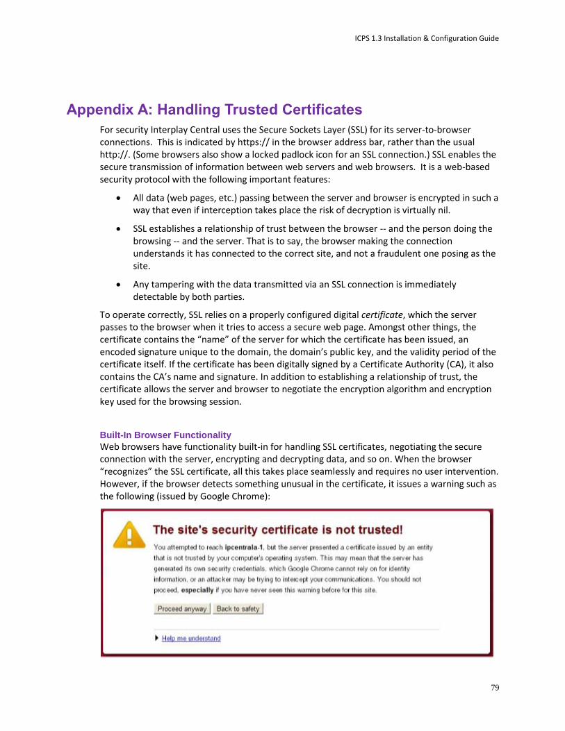
ICPS 1.3 Installation & Configuration Guide
79
Appendix A: Handling Trusted Certificates
For security Interplay Central uses the Secure Sockets Layer (SSL) for its server-to-browser connections. This is indicated by https:// in the browser address bar, rather than the usual http://. (Some browsers also show a locked padlock icon for an SSL connection.) SSL enables the secure transmission of information between web servers and web browsers. It is a web-based security protocol with the following important features:
All data (web pages, etc.) passing between the server and browser is encrypted in such a way that even if interception takes place the risk of decryption is virtually nil.
SSL establishes a relationship of trust between the browser -- and the person doing the browsing -- and the server. That is to say, the browser making the connection understands it has connected to the correct site, and not a fraudulent one posing as the site.
Any tampering with the data transmitted via an SSL connection is immediately detectable by both parties.
To operate correctly, SSL relies on a properly configured digital certificate, which the server passes to the browser when it tries to access a secure web page. Amongst other things, the certificate contains the “name” of the server for which the certificate has been issued, an encoded signature unique to the domain, the domain’s public key, and the validity period of the certificate itself. If the certificate has been digitally signed by a Certificate Authority (CA), it also contains the CA’s name and signature. In addition to establishing a relationship of trust, the certificate allows the server and browser to negotiate the encryption algorithm and encryption key used for the browsing session.
Built-In Browser Functionality
Web browsers have functionality built-in for handling SSL certificates, negotiating the secure connection with the server, encrypting and decrypting data, and so on. When the browser “recognizes” the SSL certificate, all this takes place seamlessly and requires no user intervention. However, if the browser detects something unusual in the certificate, it issues a warning such as the following (issued by Google Chrome):

ICPS 1.3 Installation & Configuration Guide
80
This appendix presents the basic issues surrounding SSL certificates. It explains why browsers issue “certificate not trusted” and other SSL warnings, and presents three approaches to handling them:
Ignoring the warnings
Generating a new self-signed certificate and adding it to the browser’s Trusted Root Certification Authorities Store
Purchasing a CA-signed certificate from a trusted Certificate Authority (CA) and adding it to the ICS server’s keystore.
SAN Certificates
If you decide to purchase a certificate/signature from a CA, or are yourself a CA, we recommend you obtain or authorize a Subject Alternative Name (SAN) certificate. SAN certificates can have a number of associated host names, domain names, IP addresses, etc., all within the same certificate.
A SAN certificate containing all the names associated with Interplay Central will eliminate the possibility of “name mismatch” warnings. Name mismatch warnings arise when the name in the browser (e.g. ics-dl360-1) does not match the “issued to” name contained in the SSL certificate (e.g. ics-dl360-1.mydomain.com). To avoid browser name-mismatch complaints, the URL typed into the browser and the address contained in the certificate must match. A SAN certificate can easily contain the server host name, IP address, and/or FQDN you might use to access Interplay Central.
SAN certificates are particularly valuable when you have a sophisticated network, complex topology, subnets, use browser redirects, or simply wish to give users different ways to connect to Interplay Central. It could arise that some users must connect to Interplay Central using the FQDN (e.g. https://ics-dl360-1.mydomain.com). Others might only need to use the shorter host name (e.g. https://ics-dl360-1). In this scenario, both names must be in the certificate if both user types are to avoid name mismatch errors.
Understanding the “Certificate Not Trusted” Warning During the installation process, the first time the Jetty web server starts it automatically generates an SSL certificate, which ICS then sends to browsers when they connect. This is known as a “self-signed” certificate, since it is generated/signed and used by the same server, rather than signed by a recognized CA. The certificate is perfectly legitimate; however, it will cause most browsers to issue a warning each time a user connects to the Interplay Central sign-in page, for two main reasons.
First, browsers only accept certificates signed by recognized CA’s without complaint. Self-signed certificates are a breach in the established “chain of trust” that starts with a recognized CA, whose own root level digital certificates are installed by default with all web browsers. Since self-signed certificates are neither signed by a CA nor pre-installed with browsers, they are flagged as untrusted.

ICPS 1.3 Installation & Configuration Guide
81
Second, as noted, some browsers may in addition complain of a name mismatch. This is because the URL used to connect to the ICS server (e.g. http://ics-dl360) contains a name that does not match the “issued to” name contained in the certificate. In manually generated certificates, the “issued to” name is most commonly the Fully Qualified Domain Name (FQDN) (e.g. ics-dl360-1.mydomain.com), permitting access the most complex network topologies. In the case of the self-signed certificate generated by Jetty during the install, the “issued to” name is usually a variation on localhost (e.g. localhost.mydomain.com or simply localhost).
Recall that you named the ICS server during the first installation steps. However, by this time, Jetty has already generated the SSL certificate using localhost. Thus, the self-signed SSL certificate automatically created during the installation process is perfectly valid, but will nevertheless flag browser warnings.
Eliminating the Certificate not Trusted and Name Mismatch Warnings With the cause of the “certificate not trusted” and name mismatch warnings understood, it can be seen that ignoring the warnings is always a possibility. However, the first and simplest approach to permanently eliminating warnings is to generate a new certificate and configure the browser — the operating system, in fact — to trust it. Telling the browser to trust the certificate eliminates the “certificate not trusted” warning. Generating a new certificate eliminates the most common name-mismatch issues that can arise even after the browser trusts the certificate.
Generating a new SSL certificate is uncomplicated, and all browsers can be configured to accept self-signed SSL certificates as trusted. The Jetty web server used by Interplay Central for its SSL connections can automatically generate a new self-signed certificate containing the renamed server. For cluster setups, you can generate a certificate “manually”, specifying the cluster FQDN, hostname, or IP address, as desired.
Note: The self-signed certificate automatically generated by Jetty cannot be used for a cluster of servers. In the case of a cluster, you must generate a self-signed certificate manually. In addition, since any node in the cluster can take on the role of master, you must also install the new certificate on each server in the cluster.
The second approach to eliminating the warning is to purchase and install an SSL certificate from a trusted Certificate Authority. Certificate Authorities — such as VeriSign, Thawte, Digicert, Comodo, GoDaddy, GlobalSign, etc. — are entities entitled to issue root certificates in the name of applicants. They are responsible for carefully authenticating individual certificate requests. The SSL certificate issued by a CA contains the CA’s own signature. Certificates issued by a CA are, generally speaking, automatically trusted by browsers.
The pros and cons of each approach are presented in the following table:
Method Description
Ignoring the warning
Ignore the warning and proceed to the Interplay Central sign-in page.
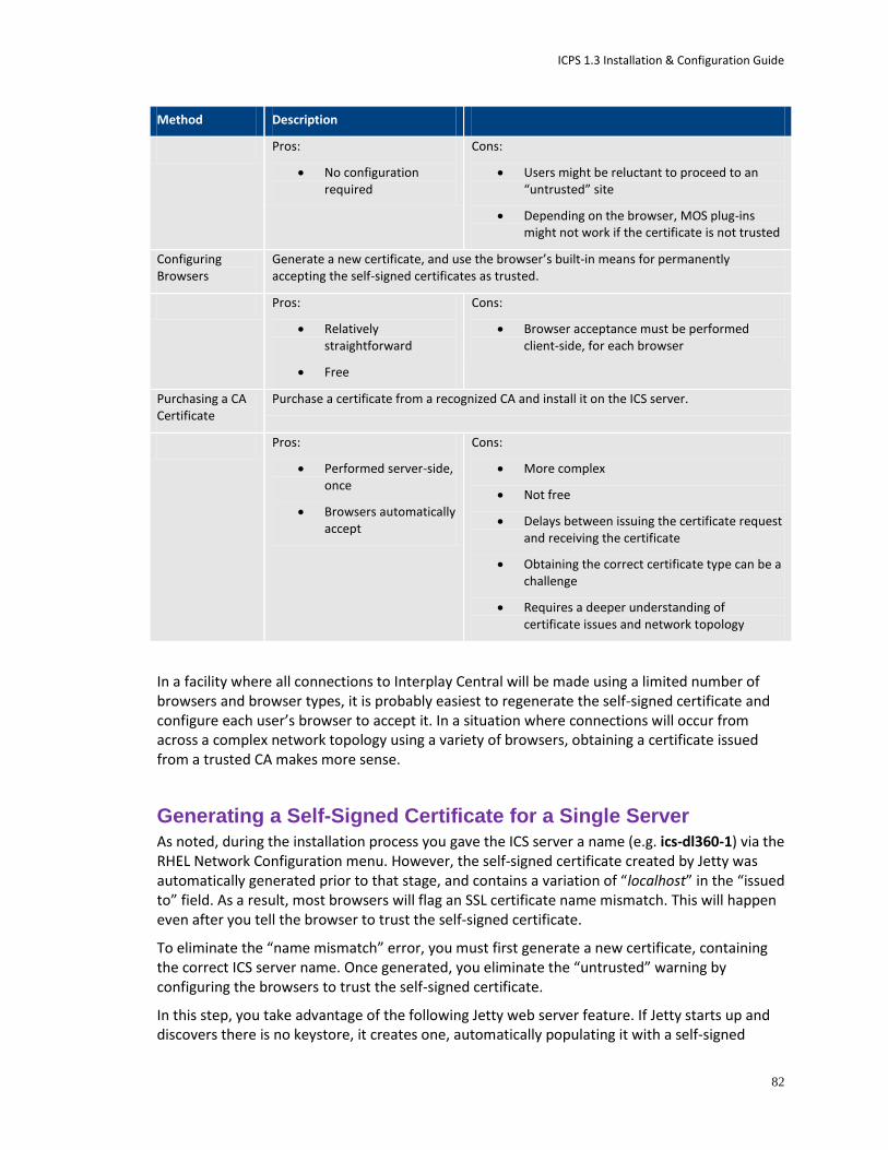
ICPS 1.3 Installation & Configuration Guide
82
Method Description
Pros:
No configuration required
Cons:
Users might be reluctant to proceed to an “untrusted” site
Depending on the browser, MOS plug-ins might not work if the certificate is not trusted
Configuring Browsers
Generate a new certificate, and use the browser’s built-in means for permanently accepting the self-signed certificates as trusted.
Pros:
Relatively straightforward
Free
Cons:
Browser acceptance must be performed client-side, for each browser
Purchasing a CA Certificate
Purchase a certificate from a recognized CA and install it on the ICS server.
Pros:
Performed server-side, once
Browsers automatically accept
Cons:
More complex
Not free
Delays between issuing the certificate request and receiving the certificate
Obtaining the correct certificate type can be a challenge
Requires a deeper understanding of certificate issues and network topology
In a facility where all connections to Interplay Central will be made using a limited number of browsers and browser types, it is probably easiest to regenerate the self-signed certificate and configure each user’s browser to accept it. In a situation where connections will occur from across a complex network topology using a variety of browsers, obtaining a certificate issued from a trusted CA makes more sense.
Generating a Self-Signed Certificate for a Single Server As noted, during the installation process you gave the ICS server a name (e.g. ics-dl360-1) via the RHEL Network Configuration menu. However, the self-signed certificate created by Jetty was automatically generated prior to that stage, and contains a variation of “localhost” in the “issued to” field. As a result, most browsers will flag an SSL certificate name mismatch. This will happen even after you tell the browser to trust the self-signed certificate.
To eliminate the “name mismatch” error, you must first generate a new certificate, containing the correct ICS server name. Once generated, you eliminate the “untrusted” warning by configuring the browsers to trust the self-signed certificate.
In this step, you take advantage of the following Jetty web server feature. If Jetty starts up and discovers there is no keystore, it creates one, automatically populating it with a self-signed
ICPS 1.3 Installation & Configuration Guide
83
certificate. (The keystore is the file where Jetty stores SSL certificates and the public-private key pairs used during the encryption process.) Since the ICS server is now named, the new certificate automatically picks up the Fully Qualified Domain Name (FQDN) (e.g. ics-dl360-1.mydomain.com) of the ICS server.
Note: Jetty picks up the FQDN from the DNS Search Path entry in the server’s Linux resolve.conf file. This value was set by you in “Configuring the Hostname and Static Network Route” on page 44.
Note: Once you generate the new certificate and install the certificate in the Trusted Certificate Store, users will need to enter the FQDN into the browser address bar, to avoid name-mismatch warnings.
Note: This procedure in this section only applies to a single-server installation. If you have set up a cluster, refer to the instructions in “Generating a Self-Signed Certificate for a Server Cluster” on page 84 instead.
To generate a new self-signed certificate for a single server:
1. Log in to the ICS server as root and navigate to the directory containing the Jetty keystore:
cd /opt/avid/etc/avid/avid-interplay-central/ssl
2. Verify the status of the avid-interplay-central service:
service avid-interplay-central status
The system responds that Avid Interplay Central is running.
3. Stop the service:
service avid-interplay-central stop
The system responds that Avid Interplay Central has been stopped.
4. Delete the Jetty keystore (which contains the current self-signed SSL certificate):
rm jetty.keystore
You are asked to confirm the deletion.
5. Restart the avid-interplay-central service (which also restarts the Jetty web server):
service avid-interplay-central restart
The system responds that the Avid Interplay Central process has been started. The new keystore and SSL certificate are created automatically by Jetty.
6. Verify the new Jetty keystore has been created:
ls -l
The system lists the contents of the directory, including the following file:
jetty.keystore

ICPS 1.3 Installation & Configuration Guide
84
Now that you have eliminated potential name-mismatch browser SSL warnings, you must configure each browser to trust the certificate. This is done by installing the certificate into the OS-level Trusted Root Certification Authorities store.
Proceed to one or more of the following:
”Configuring Google Chrome (Windows)” on page 89.
”Configuring Internet Explorer (Windows)” on page 93.
”Configuring Safari (Mac OS)” on page 97.
Generating a Self-Signed Certificate for a Server Cluster Recall that you address a cluster using the IP address allocated for it by the IT department (e.g. 224.XXX.XXX.XXX). Alternately, you might have associated a more memorable name (e.g. icps-cluster) with the IP address using a DNS Manager and/or name server. This means that in a cluster setup, the address entered into the browser is unrelated to the IP addresses (or names) of the servers inside the cluster.
However, the SSL certificate that is automatically generated by Jetty picks up the FQDN of the machine on which it is generated. It does not pick up the cluster name (or IP address). Further, for each node in the cluster Jetty will generate a certificate with a different embedded FQDN.
Note: Jetty picks up the FQDN from the DNS Search Path entry in the server’s Linux resolve.conf file. This value was set by you in “Configuring the Hostname and Static Network Route” on page 44.
As a result of the different SSL certificates served by the cluster, each with different “issued to” values, name mismatches will be repeatedly flagged by the browser. This will be the case even if the certificate is otherwise trusted. Thus, using automatically generated SSL certificates in a cluster setup is not possible. To eliminate the name mismatch warning, you generate a new self-signed certificate for each server in the cluster, specifying its contents explicitly. In particular, you specify the FQDN of the cluster itself, not the individual servers within the cluster.
In this procedure you use the Jetty keytool utility to generate a new self-signed certificate with contents set explicitly. The utility also generates the private-public key pair associated with a certificate, and the keystore where they are all stored. You also update the Interplay Central application properties file so it can make use of the new certificate.
Before You Begin
The procedure in this section requires the following:
The name associated with the static IP address allocated for the cluster (e.g. ics-cluster).
To generate a new self-signed certificate for a cluster:
1. On each server in the cluster log as the root user.
2. Use the Linux ping command to obtain the FQDN of the cluster:
ping <cluster_name>
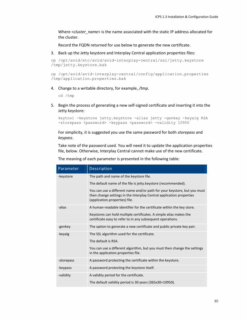
ICPS 1.3 Installation & Configuration Guide
85
Where <cluster_name> is the name associated with the static IP address allocated for the cluster.
Record the FQDN returned for use below to generate the new certificate.
3. Back up the Jetty keystore and Interplay Central application properties files:
cp /opt/avid/etc/avid/avid-interplay-central/ssl/jetty.keystore
/tmp/jetty.keystore.bak
cp /opt/avid/avid-interplay-central/config/application.properties
/tmp/application.properties.bak
4. Change to a writable directory, for example, /tmp.
cd /tmp
5. Begin the process of generating a new self-signed certificate and inserting it into the Jetty keystore:
keytool -keystore jetty.keystore -alias jetty -genkey -keyalg RSA
-storepass <password> -keypass <password> -validity 10950
For simplicity, it is suggested you use the same password for both storepass and keypass.
Take note of the password used. You will need it to update the application properties file, below. Otherwise, Interplay Central cannot make use of the new certificate.
The meaning of each parameter is presented in the following table:
Parameter Description
-keystore The path and name of the keystore file.
The default name of the file is jetty.keystore (recommended).
You can use a different name and/or path for your keystore, but you must then change settings in the Interplay Central application properties (application.properties) file.
-alias A human-readable identifier for the certificate within the key store.
Keystores can hold multiple certificates. A simple alias makes the certificate easy to refer to in any subsequent operations.
-genkey The option to generate a new certificate and public-private key pair.
-keyalg The SSL algorithm used for the certificate.
The default is RSA.
You can use a different algorithm, but you must then change the settings in the application.properties file.
-storepass A password protecting the certificate within the keystore.
-keypass A password protecting the keystore itself.
-validity A validity period for the certificate.
The default validity period is 30 years (365x30=10950).
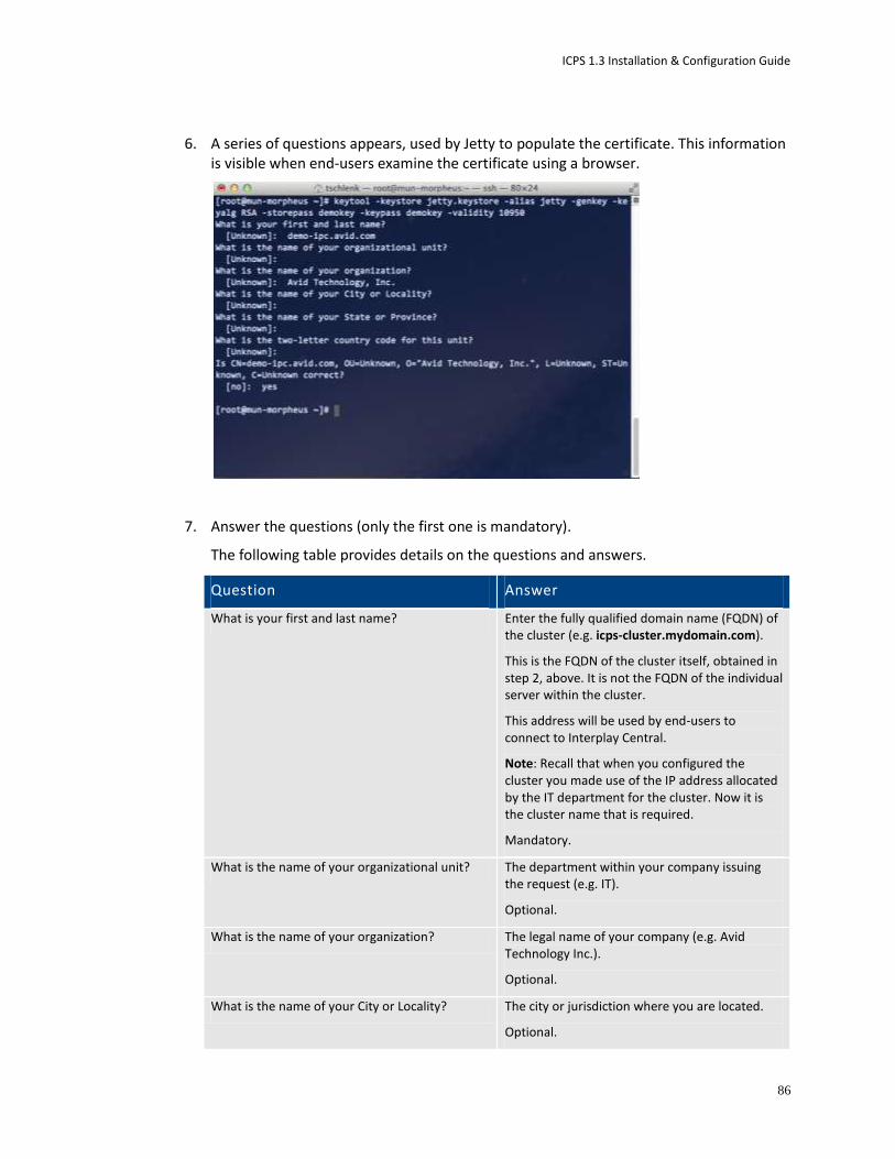
ICPS 1.3 Installation & Configuration Guide
86
6. A series of questions appears, used by Jetty to populate the certificate. This information is visible when end-users examine the certificate using a browser.
7. Answer the questions (only the first one is mandatory).
The following table provides details on the questions and answers.
Question Answer
What is your first and last name? Enter the fully qualified domain name (FQDN) of the cluster (e.g. icps-cluster.mydomain.com).
This is the FQDN of the cluster itself, obtained in step 2, above. It is not the FQDN of the individual server within the cluster.
This address will be used by end-users to connect to Interplay Central.
Note: Recall that when you configured the cluster you made use of the IP address allocated by the IT department for the cluster. Now it is the cluster name that is required.
Mandatory.
What is the name of your organizational unit? The department within your company issuing the request (e.g. IT).
Optional.
What is the name of your organization? The legal name of your company (e.g. Avid Technology Inc.).
Optional.
What is the name of your City or Locality? The city or jurisdiction where you are located.
Optional.
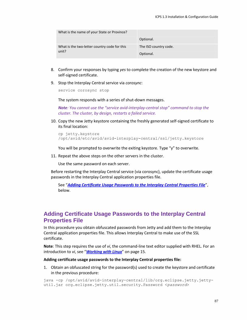
ICPS 1.3 Installation & Configuration Guide
87
What is the name of your State or Province?
Optional.
What is the two-letter country code for this unit?
The ISO country code.
Optional.
8. Confirm your responses by typing yes to complete the creation of the new keystore and self-signed certificate.
9. Stop the Interplay Central service via corosync:
service corosync stop
The system responds with a series of shut-down messages.
Note: You cannot use the “service avid-interplay-central stop” command to stop the cluster. The cluster, by design, restarts a failed service.
10. Copy the new Jetty keystore containing the freshly generated self-signed certificate to its final location:
cp jetty.keystore
/opt/avid/etc/avid/avid-interplay-central/ssl/jetty.keystore
You will be prompted to overwrite the exiting keystore. Type “y” to overwrite.
11. Repeat the above steps on the other servers in the cluster.
Use the same password on each server.
Before restarting the Interplay Central service (via corosync), update the certificate usage passwords in the Interplay Central application properties file.
See “Adding Certificate Usage Passwords to the Interplay Central Properties File”, below.
Adding Certificate Usage Passwords to the Interplay Central Properties File In this procedure you obtain obfuscated passwords from Jetty and add them to the Interplay Central application properties file. This allows Interplay Central to make use of the SSL certificate.
Note: This step requires the use of vi, the command-line text editor supplied with RHEL. For an introduction to vi, see “Working with Linux” on page 15.
Adding certificate usage passwords to the Interplay Central properties file:
1. Obtain an obfuscated string for the password(s) used to create the keystore and certificate in the previous procedure:
java -cp /opt/avid/avid-interplay-central/lib/org.eclipse.jetty.jetty-
util.jar org.eclipse.jetty.util.security.Password <password>

ICPS 1.3 Installation & Configuration Guide
88
Where <password> is the password you used to protect the certificate within the keystore (e.g. Avid123).
The system responds by outputting the password, the obfuscated password string (OBF:) and its MD5 hash value (MD5:).
The following represents sample output. It is the string following OBF that is needed:
Avid123
OBF:1c3x1mf71jnb1sov1jk71mbf1c35
MD5:4c88dafcf38a9b90b1e32efe798f95f0
2. If you used a different password to protect the Jetty keystore itself, repeat the step for the second password.
3. Edit the Interplay Central application properties file using a text editor such as vi:
vi /opt/avid/avid-interplay-central/config/application.properties
4. Locate the entry for the password used to protect the certificate:
system.org.ops4j.pax.web.ssl.password=OBF\:1c3x1mf71jnb1sov1jk71mbf1c35
5. Replace obfuscated string (shown in bold, above) with the one you generated.
6. Locate the entry for the password used to protect the Jetty keystore:
system.org.ops4j.pax.web.ssl.keypassword=OBF\:1c3x1mf71jnb1sov1jk71mbf1c35
7. Replace obfuscated string (shown in bold, above) with the one you generated.
8. Save and exit the file:
<Esc>:wq
9. Replace the above values in the other servers in the cluster, then restart the Interplay Central services:
service corosync restart
Interplay Central is now using the SSL Certificate you created for its HTTPS connections.
Now that you have eliminated the name-mismatch warnings, you must configure each browser to trust the certificate. This is done by installing the certificate into the OS-level Trusted Root Certification Authorities store.
Proceed to one or more of the following:
”Configuring Google Chrome (Windows)” on page below.
”Configuring Internet Explorer (Windows)” on page 93.
”Configuring Safari (Mac OS)” on page 97.
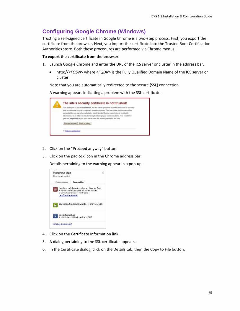
ICPS 1.3 Installation & Configuration Guide
89
Configuring Google Chrome (Windows) Trusting a self-signed certificate in Google Chrome is a two-step process. First, you export the certificate from the browser. Next, you import the certificate into the Trusted Root Certification Authorities store. Both these procedures are performed via Chrome menus.
To export the certificate from the browser:
1. Launch Google Chrome and enter the URL of the ICS server or cluster in the address bar.
http://<FQDN> where <FQDN> is the Fully Qualified Domain Name of the ICS server or cluster.
Note that you are automatically redirected to the secure (SSL) connection.
A warning appears indicating a problem with the SSL certificate.
2. Click on the “Proceed anyway” button.
3. Click on the padlock icon in the Chrome address bar.
Details pertaining to the warning appear in a pop-up.
4. Click on the Certificate Information link.
5. A dialog pertaining to the SSL certificate appears.
6. In the Certificate dialog, click on the Details tab, then the Copy to File button.
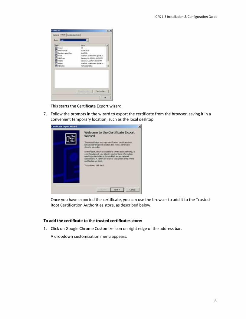
ICPS 1.3 Installation & Configuration Guide
90
This starts the Certificate Export wizard.
7. Follow the prompts in the wizard to export the certificate from the browser, saving it in a convenient temporary location, such as the local desktop.
Once you have exported the certificate, you can use the browser to add it to the Trusted Root Certification Authorities store, as described below.
To add the certificate to the trusted certificates store:
1. Click on Google Chrome Customize icon on right edge of the address bar.
A dropdown customization menu appears.

ICPS 1.3 Installation & Configuration Guide
91
2. Choose Settings from the dropdown menu.
The Chrome Settings page appears.
3. Click on the “Show advanced settings” link.
The page expands to show more settings.
4. Click on the Manage Certificates button in the HTTPS/SSL category.
5. A Certificates dialog appears showing certificates arranged by category.
6. In the Certificates dialog, click the Import button.
The Windows Certificate Import Wizard appears.
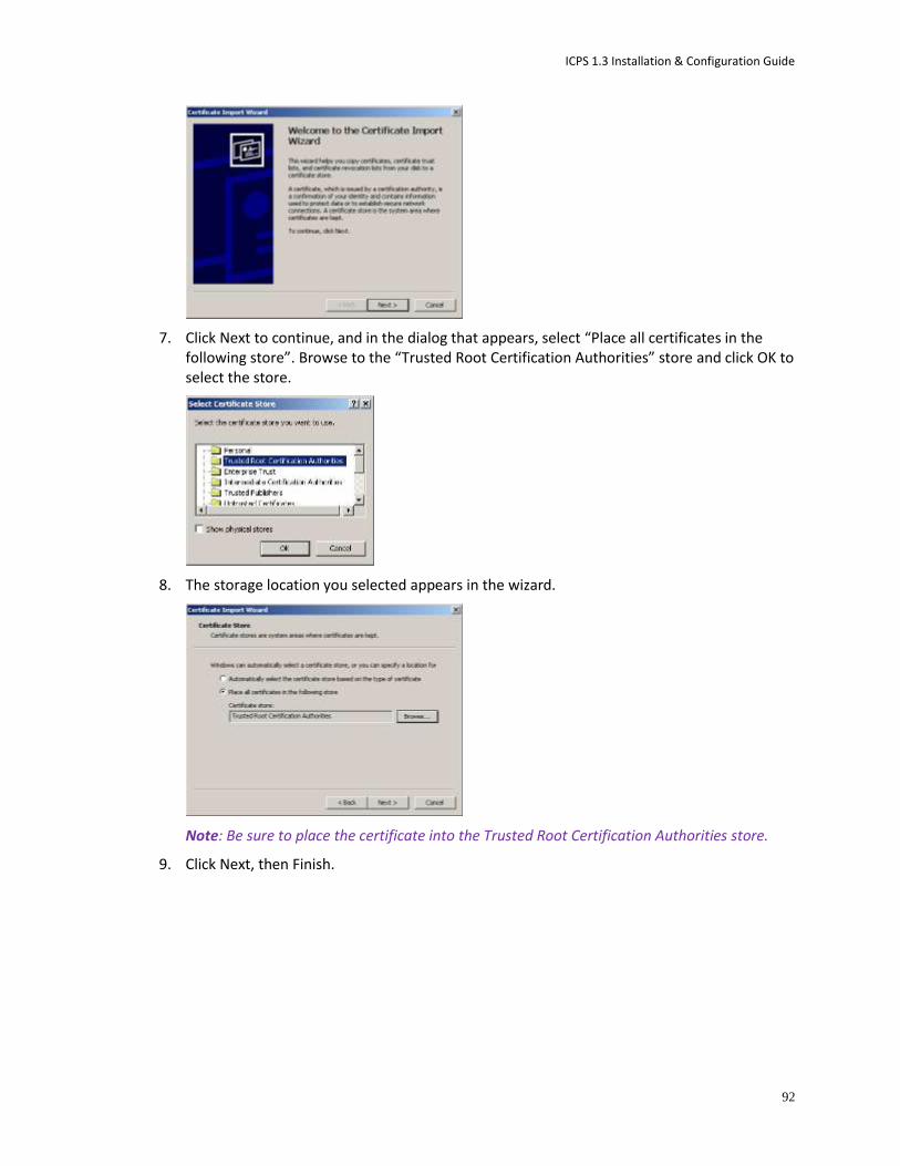
ICPS 1.3 Installation & Configuration Guide
92
7. Click Next to continue, and in the dialog that appears, select “Place all certificates in the following store”. Browse to the “Trusted Root Certification Authorities” store and click OK to select the store.
8. The storage location you selected appears in the wizard.
Note: Be sure to place the certificate into the Trusted Root Certification Authorities store.
9. Click Next, then Finish.

ICPS 1.3 Installation & Configuration Guide
93
10. A final security warning dialog appears, asking you to confirm installation of the certificate. Click Yes.
A confirmation dialog appears indicting success.
11. Restart Chrome and enter the FQDN of the ICS server or cluster in the address bar.
The browser loads Interplay Central without issuing certificate warnings.
Configuring Internet Explorer (Windows) Internet Explorer provides an efficient mechanism for adding self-signed (or otherwise untrusted) certificates to the Trusted Root Certification Authorities store.
To add a certificate to the trusted certificates store:
1. Launch Internet Explorer and enter the URL of the ICS server or cluster in the address bar.
http://<FQDN> where <FQDN> is the Fully Qualified Domain Name of the ICS server or cluster.
Note that you are automatically redirected to the secure (SSL) connection.
A warning appears indicating a problem with the SSL certificate.
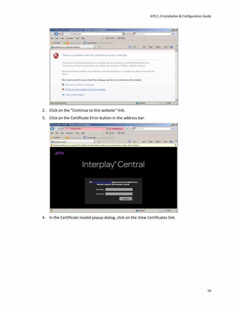
ICPS 1.3 Installation & Configuration Guide
94
2. Click on the “Continue to this website” link.
3. Click on the Certificate Error button in the address bar.
4. In the Certificate Invalid popup dialog, click on the View Certificates link.
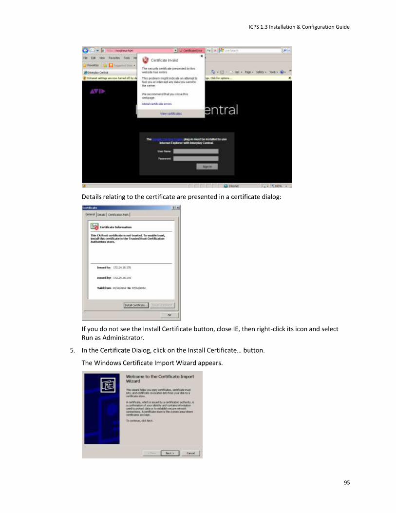
ICPS 1.3 Installation & Configuration Guide
95
Details relating to the certificate are presented in a certificate dialog:
If you do not see the Install Certificate button, close IE, then right-click its icon and select Run as Administrator.
5. In the Certificate Dialog, click on the Install Certificate… button.
The Windows Certificate Import Wizard appears.
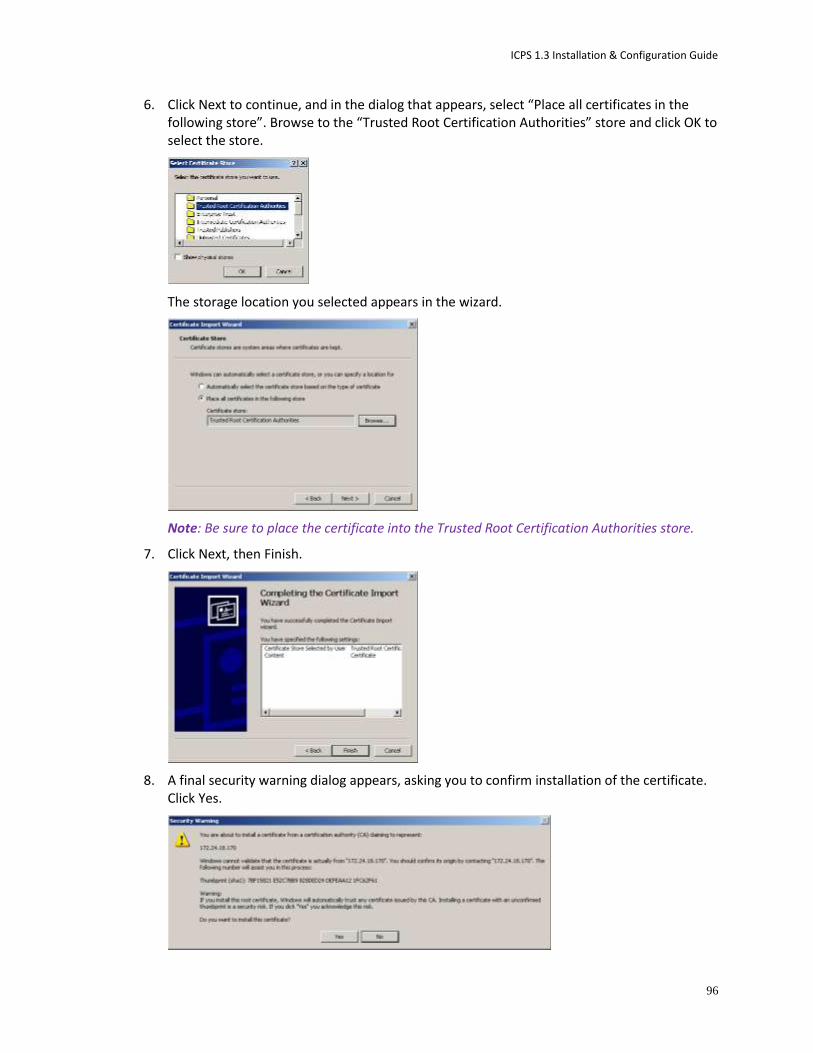
ICPS 1.3 Installation & Configuration Guide
96
6. Click Next to continue, and in the dialog that appears, select “Place all certificates in the following store”. Browse to the “Trusted Root Certification Authorities” store and click OK to select the store.
The storage location you selected appears in the wizard.
Note: Be sure to place the certificate into the Trusted Root Certification Authorities store.
7. Click Next, then Finish.
8. A final security warning dialog appears, asking you to confirm installation of the certificate. Click Yes.

ICPS 1.3 Installation & Configuration Guide
97
The Certificate Import Wizard indicates success.
9. Restart Internet Explorer and enter the FQDN of the ICS server or cluster in the address bar.
The browser loads Interplay Central without issuing certificate warnings.
Configuring Safari (Mac OS) In Mac OS, you must add the self-signed certificate to the Mac OS system keychain. This is easily done via the Safari browser itself.
To add a certificate to the trusted certificates store:
1. Launch Safari and enter the URL of the ICS server or cluster in the address bar.
http://<FQDN> where <FQDN> is the Fully Qualified Domain Name of the ICS server or cluster.
Note that you are automatically redirected to the secure (SSL) connection.
A warning appears indicating a problem with the SSL certificate.
2. Click the Show Certificate button to display details about the certificate.
3. Put a checkmark in the “Always trust” checkbox and click Continue.
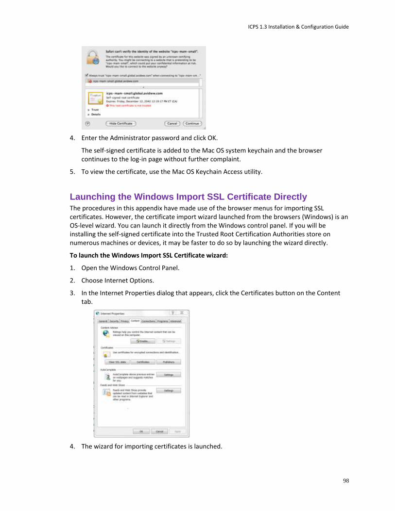
ICPS 1.3 Installation & Configuration Guide
98
4. Enter the Administrator password and click OK.
The self-signed certificate is added to the Mac OS system keychain and the browser continues to the log-in page without further complaint.
5. To view the certificate, use the Mac OS Keychain Access utility.
Launching the Windows Import SSL Certificate Directly The procedures in this appendix have made use of the browser menus for importing SSL certificates. However, the certificate import wizard launched from the browsers (Windows) is an OS-level wizard. You can launch it directly from the Windows control panel. If you will be installing the self-signed certificate into the Trusted Root Certification Authorities store on numerous machines or devices, it may be faster to do so by launching the wizard directly.
To launch the Windows Import SSL Certificate wizard:
1. Open the Windows Control Panel.
2. Choose Internet Options.
3. In the Internet Properties dialog that appears, click the Certificates button on the Content tab.
4. The wizard for importing certificates is launched.

ICPS 1.3 Installation & Configuration Guide
99
Obtaining a Trusted CA-signed Certificate SSL certificates obtained and signed by a CA are automatically trusted by browsers. No warnings appear when a connection is made to a secure web page, nor do you need to add them to the Trusted Root Certification Authorities store (since the CA’s root certificate is already there).
Note: Standard SSL certificates secure a single host name, IP address or FQDN. SAN certificates can contain secure multiple servers and contain name variations, and is the recommended certificate. For details, see “SAN Certificates” on page 80.
To obtain a trusted CA-signed certificate:
The process for obtaining a certificate varies with each CA, but always involves generating a Certificate Signing Request (CSR), and installing the new signed certificate into the keystore. The steps are summarized below.
1. Create the keystore containing a private key for the server.
The private key is needed to generate the CSR.
2. Generate the CSR.
The CA may provide a custom tool for generating the CSR. The form of the command for the Jetty keytool utility is as follows:
keytool –certreq –alias jetty –keystore jetty.keystore –file
jetty.csr
3. Add the CA-signed certificate to the ICS server Jetty keystore.
See “Adding a CA-Signed Certificate to the ICS Server” below.
In the case of a cluster, add it to each keystore in the cluster
Adding a CA-Signed Certificate to the ICS Server
Once you have obtained an SSL certificate that has been signed by a recognized Certificate Authority (CA) you can add it to the ICS server Jetty keystore. This is a two-step process. In the first step, you generate a password-protected Public-Key Cryptography Standards (.pkcs12) file containing your private key and the certificate provided by the CA. You also import the PKCS file into the Jetty keystore. In the second step, you add obfuscated certificate usage passwords to the Interplay Central application properties file.
The procedures presented here require that you have the following files in your possession:
PEM (.pem) file: Also known as a concatenated certificate container file, this file contains the CA-signed certificate.
Key file: The file containing your private key for the certificate.
Note: For a cluster, adapt the instructions to install the CA-signed certificate on each server in the cluster.
Adding a trusted certificate to the ICS server keystore:
1. Log in to the ICS server as the root user.

ICPS 1.3 Installation & Configuration Guide
100
2. Back up the Jetty keystore and Interplay Central application properties files:
cp /opt/avid/etc/avid/avid-interplay-central/ssl/jetty.keystore
/tmp/jetty.keystore.bak
cp /opt/avid/avid-interplay-central/config/application.properties
/tmp/application.properties.bak
3. Copy the private key (.key) file (e.g. ics-dl360-1.key) you generated and the PEM (.pem) file (e.g. ics-dl360.pem) received from the CA to a directory on the ICS server.
4. Change to the above directory, and combine the private key file and PEM file into a single Public-Key Cryptography Standards (.pkcs12) file that can be added to the Jetty keystore:
openssl pkcs12 -inkey <privatekeyfile>.key -in <certificatefile>.pem
-export -out jetty.pkcs12
5. Enter an export password as prompted.
Take note of the export password for the next step.
6. Create the Jetty keystore, and import the file you created into it:
keytool -importkeystore -srckeystore jetty.pkcs12 -srcstoretype
PKCS12 -destkeystore jetty.keystore
7. At the prompts provide a destination password for the Jetty keystore, and enter the export password (source keystore password) used in the previous step.
For simplicity, it is suggested you use the same password for both.
8. Stop the Avid Interplay Central service:
service avid-interplay-central stop
For a cluster, use the following command instead:
service corosync stop
9. Copy the new Jetty keystore containing the CA certificate to its final location:
cp jetty.keystore
/opt/avid/etc/avid/avid-interplay-central/ssl/jetty.keystore
Before restarting the Interplay Central services, add the certificate usage passwords to the properties file, below.
Adding certificate usage passwords to the Interplay Central properties file:
In this procedure you obtain obfuscated passwords from Jetty and add them to the Interplay Central properties file. This allows Interplay Central to make use of the SSL certificate.
Note: This step requires the use of vi, the command-line text editor supplied with RHEL. For an introduction to vi, see “Working with Linux” on page 15.
1. Obtain an obfuscated string for the password used to create the jetty.pkcs12 file in the previous procedure:
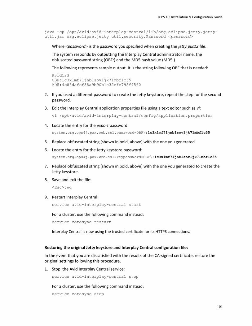
ICPS 1.3 Installation & Configuration Guide
101
java -cp /opt/avid/avid-interplay-central/lib/org.eclipse.jetty.jetty-
util.jar org.eclipse.jetty.util.security.Password <password>
Where <password> is the password you specified when creating the jetty.pks12 file.
The system responds by outputting the Interplay Central administrator name, the obfuscated password string (OBF:) and the MD5 hash value (MD5:).
The following represents sample output. It is the string following OBF that is needed:
Avid123
OBF:1c3x1mf71jnb1sov1jk71mbf1c35
MD5:4c88dafcf38a9b90b1e32efe798f95f0
2. If you used a different password to create the Jetty keystore, repeat the step for the second password.
3. Edit the Interplay Central application properties file using a text editor such as vi:
vi /opt/avid/avid-interplay-central/config/application.properties
4. Locate the entry for the export password:
system.org.ops4j.pax.web.ssl.password=OBF\:1c3x1mf71jnb1sov1jk71mbf1c35
5. Replace obfuscated string (shown in bold, above) with the one you generated.
6. Locate the entry for the Jetty keystore password:
system.org.ops4j.pax.web.ssl.keypassword=OBF\:1c3x1mf71jnb1sov1jk71mbf1c35
7. Replace obfuscated string (shown in bold, above) with the one you generated to create the Jetty keystore.
8. Save and exit the file:
<Esc>:wq
9. Restart Interplay Central:
service avid-interplay-central start
For a cluster, use the following command instead:
service corosync restart
Interplay Central is now using the trusted certificate for its HTTPS connections.
Restoring the original Jetty keystore and Interplay Central configuration file:
In the event that you are dissatisfied with the results of the CA-signed certificate, restore the original settings following this procedure.
1. Stop the Avid Interplay Central service:
service avid-interplay-central stop
For a cluster, use the following command instead:
service corosync stop

ICPS 1.3 Installation & Configuration Guide
102
2. Overwrite the Jetty keystore you created with the original:
cp /tmp/jetty.keystore.bak /opt/avid/etc/avid/avid-interplay-
central/ssl/jetty.keystore
3. Overwrite the modified Interplay Central properties file with the original:
cp /tmp/application.properties.bak /opt/avid/avid-interplay-
central/config/application.properties
4. Restart the Avid Interplay Central service:
service avid-interplay-central start
For a cluster, use the following command instead:
service corosync restart
The Interplay Central Application Properties File The following table summarizes the entries in the Interplay Central application properties file that are related to SSL certificates. Interplay Central makes use of these values to send SSL certificates to browsers.
Keys Description
system.org.osgi.service.ssl.password The password protecting the certificate within the keystore.
Must match the value given for the -storepass parameter when you generate the new certificate.
Clear text or Jetty obfuscated (recommended).
system.org.osgi.service.ssl.keypassword The password protecting the keystore itself.
Must match the value given for -keypass when you generated the new keystore.
Clear text or Jetty obfuscated (recommended).
system.org.osgi.service.ssl.algorithm The encryption algorithm.
Must match the value given for -keyalg when you generated the new keystore.
Default is RSA.
system.org.osgi.service.https.keystore.path The path and name of the key store file.
Must match the value given for -keystore when you generated the new keystore.
The path is relative to the standard SSL folder used for storing the key store file.
ICPS 1.3 Installation & Configuration Guide
103
Appendix B: Migrating the Database with the User Management Utilities Tool
You can migrate your Windows-based database to the new RedHat Linux Interplay Common Services server using the User Management Utilities tool. The procedure includes two steps:
1. Copy the Windows-based database and migrate it to your Linux system.
2. Migrate system settings to the bus-based storage on the Linux system.
The initial installation of the UMS creates a default user name and password. After you migrate your database, the default credentials change on your RedHat Linux server, with the default user name and password replaced by those used for the existing Windows database that you are migrating to the new Linux server.
Note: You need to log in to the Linux server as root to complete the procedures in this section.
To migrate the database:
1. On the Windows server used for your current database, stop the Interplay Central User Management service.
2. Check to make sure there is no lock file in the database directory. If one exists, wait for the UMS to completely stop and removes the lock file. If you attempt to migrate the database while a lock file persists, the database find can become corrupted.
3. Copy the Windows database file to an available directory on the new RedHat Linux server — for example, /tmp.
The Windows database file is located at C:\ProgramData\Avid\Avid
Interplay Central User Management Service\db\database.h2.db.
Caution: Do not rename the database file.
4. From a terminal window on the RedHat Linux server, check the status of the UMS by typing the following: service avid-ums status.
5. From a terminal window on the Linux server, start the database migration by typing the following command: avid-ums-admin-tool -mdb [admin-password] [h2-DB-path] [postgres-superuser-name] [postgres-superuser-
password].
For example: avid-ums-admin-tool -mdb Avid123 /tmp/database.h2.db postgres pass. An error message informs you if you type an incorrect path for your database file.
A message informs you when the migration completes: Migration is successfully done.
To migrate the system settings, do the following:
From a terminal window on the Linux server, type the following command: avid-ums-admin-tool -ms [cloud-bus-url] [ums-admin-password].

ICPS 1.3 Installation & Configuration Guide
104
For example: avid-ums-admin-tool -ms localhost:61665 Avid123.
A message informs you when the settings migration completes: Migration completed successfully.
Appendix C: Installing the Chrome Extension for Interplay Central MOS Plug-Ins
Interplay Central provides support for MOS Active-X plug-ins. For example, Deko Select is a plug-in for a newsroom computer system’s interface that allows a user to drag and drop graphic templates directly into the story. These plug-ins are specific to iNEWS workflows, and they are available only in Basic and Video layouts.
Active X plug-ins are not supported in the Safari browser.
Setting Up Your Browser
The Chrome browser requires an extension that lets you install MOS plug-ins. The first time you sign in to Interplay Central, a dialog box asks if you want to use MOS plug-ins.
If you click yes, an installer is downloaded from the ICS server. If you are informed that a pop-up was blocked, allow pop-ups from the ICS server and then refresh the page. Click the .exe file to install the extension.
If you click no, and later want to use plug-ins, enable MOS as described below. The next time you sign in or refresh the application, a blank window opens and the installer is downloaded. Click the .exe file to install the extension.
Enabling MOS To use plug-ins, you need to enable MOS in Interplay Central. Select Home > User Settings > MOS and then select “MOS enabled.”
Uninstalling the Chrome Extension If you need to uninstall the Chrome Extension, use the Windows Control Panel. Do not use the Chrome Extensions page.
1. Click Start and select Control Panel.
2. Click Programs and Features.
3. Right-click Avid interplay Central MOS plugin and select Uninstall. Click Yes and follow the prompts.
For more information about MOS plug-ins, see the Avid Interplay Central User’s Guide or the Avid Interplay Central Help.

ICPS 1.3 Installation & Configuration Guide
105
Appendix D: Installation Pre-Flight Checklist
This section lists all the information needed to perform the installation. Please gather the information from the customer before beginning the installation process. Take care to collect all the information relevant to the ICS deployment you are undertaking.
Default Password Information The installation scripts establish login credentials for RHEL and Interplay Central at the administrator level. These enable you to carry out the work of installing and configuring ICS with the needed level of authority. It is highly recommended you secure the system by changing the default passwords at the first opportunity, as described in this guide.
Note: Obtain new administrator passwords that are in accordance with the customer’s own password enforcement policies.
For Linux the following default log in credentials are created:
Linux administrator user name and password (case-sensitive):
Default administrator user name: root
Default root password: Avid123
For Interplay Central the following default login credentials are created:
Interplay Central administrator user name and password (case-sensitive):
Default administrator user name: Administrator
Default root password: Avid123
Contact Information Before beginning, please obtain contact information for the following people:
Avid Contact:
Phone Number: Email:
In-House IT Specialist:
Phone Number: Email:
Network Administrator:
Phone Number: Email:
Pre-Flight Product Team Contact:

ICPS 1.3 Installation & Configuration Guide
106
Phone Number: Email:
Hardware This section shall mention the hardware requirements to perform the setup.
Windows Machine (32-bit or 64-bit) (e.g. Window XP/Vista/7 laptop or desktop computer): Used to download software from the Internet and prepare the USB key.
8GB USB Key: Used to contain RHEL OS, the ICS installation scripts, etc.
ICS Servers: Already installed or ready to install in the machine room where they will reside.
Software This section shall indicate where to get the files if you don’t have them.
ICS installation package: USB_v1.3.zip
RHEL 6.2 installation DVD or image (.iso) file
GlusterFS files (needed for clustering)
If you do not have all the software you need, see “Obtaining the Software” on page 21.
Network Settings Obtain the following information from your network administrator and enter it in the spaces provided. These items are needed by Linux.
Facility Static IP address:
Facility Netmask:
Default Gateway IP:
Primary DNS server:
Secondary DNS server:
DNS Search Path Domain:
ICS Server Information For each ICS server record the information indicated in this section. You might find it helpful to print this page, once for each server.
Please indicate how you will be gaining access the server(s):
Directly by connecting a monitor and keyboard to the server(s)
Remotely via KVM (keyboard, video and mouse) switch, or comparable solution
ICPS 1.3 Installation & Configuration Guide
107
For each server, record the following information in the spaces provided.
Server Machine Name (e.g. ics-dl360-1, ics-dl380-1):
Note: This is the host name only (e.g. ics-dl360-1),that is, the name of the machine. Do not use the fully qualified domain names (e.g. ics-dl360-1.mydomain.com or ics-dl360-1.mydomain.local)
Type:
HP Proliant DL360 G8
HP ProliantDL380 G7
Other:
Hard Drives1:
Number of Hard Drives Used for the OS (e.g. 2):
Number of Hard Drives Reserved for the Cache (e.g. 6):
System Drives Bay and Slots (e.g. Bay 1 Slots 1 &2):
Cache Drives Bay and Slots (e.g. Bay 2 Slots 1 to 8):
Network Interface Cards (NICs) Present in the Enclosure:
Myricom 10GigE
Qualified Intel PRO/1000 (e1000) based GigE NIC
Other:
Indicate the Network Interface Card (NICs) used to connect ICS to the network:
Myricom 10GigE
Qualified Intel PRO/1000 (e1000) based GigE NIC
Other:
Cluster Information
Are you setting up a cluster? YES / NO
Does your network already use multicasting? YES / NO
How many ICS servers will be in the cluster?
Provide the machine names for each one (e.g. ics-dl360-1, ics-dl380-1):
1 The number and location of the hard drives might only be known once you boot the server and enter the
BIOS screens.
ICPS 1.3 Installation & Configuration Guide
108
Note: This is the host name only (e.g. ics-dl360-1),that is, the name of the machine. Do not use the fully qualified domain names (e.g. ics-dl360-1.mydomain.com or ics-dl360-1.mydomain.local)
Obtain the following information from your network administrator and enter it in the spaces provided:
The static IP address allocated for the cluster (e.g. : 192.XXX.XXX.XXX):
If you network does not already use multicasting, write “use default multicast address” in the space above.
An IP address that is always available (e.g. a network router):
The email addresses of those to whom automated notifications about the status of the cluster should be sent (e.g. network administrators):
iNews Information
Are MOS plug-ins used? YES / NO
Interplay Central provides support for MOS Active-X plug-ins. For example, Deko Select is a plug-in for a newsroom computer system’s interface that allows a user to drag and drop graphic templates directly into the story. These plug-ins are specific to iNEWS workflows, and they are available only in Basic and Video layouts.
Interplay Central and Interplay Sphere Information
Interplay Credentials (e.g. ics-interplay):
Log into Interplay Central as an Interplay administrator, and create a unique set of user credentials (user name and password) for use by the ICS software, with the following attributes:
The credentials should not be shared with any human users
Permission to read all folders in the workgroup
We recommend using a name that indicates the purpose of the user credentials (e.g. ics-interplay)
Interplay Central UI

ICPS 1.3 Installation & Configuration Guide
109
The Interplay Central UI is used to configure ICS.
For future reference, record the IP address of Interplay Central (e.g. http://<hostname> or http://<cluster-IP>) as determined during the installation process2:
Interplay Central default administrator user name and password (case-sensitive):
Default administrator user name: Administrator
Default root password: Avid123
Interplay Production Information
Obtain the following information from the Interplay administrator and enter it in the spaces provided.
Interplay Production (Interplay Engine) server hostname:
User name reserved for ICS (e.g. ics-interplay):
Password for above user:
Interplay Central Distribution Service – Service URL (e.g. https://<server>:<port>):
Media Indexer host name:
Note: If the Interplay media indexer is connected to a High Availability Group (HAG), enter the host name of the active Media Indexer.
Interplay Workgroup name:
Lookup server host name:
Will you be making use of multi-resolution workflows? Y / N
ISIS Information
What kind of connection will you make to the ISIS:
Zone 1 (direct connection)
Zone 2 (via a network switch)
Zone 2 Information
If connecting the ICS server(s) to the ISIS via a Zone2 connection, obtain the following information from your ISIS and/or network administrator:
2 The IP Address of the ICS Portal will only be known once you install the ICS software.

ICPS 1.3 Installation & Configuration Guide
110
ISIS System Director(s) IP addresses:
Indicate the speed of the connection to the ISIS:
GigE
10GigE
Is more than network connection available? YES / NO
If yes, obtain the following information from your ISIS and/or network administrator and enter it in the spaces provided.
NIC device name used for ISIS connection (e.g. eth0):
All other active NIC device names not used by ISIS (e.g. eth1, eth2):
ISIS Credentials (e.g. ics-isis):
While logged in to the ISIS as administrator, create a unique set of user credentials for use by the ICS software, with the following attributes:
The credentials should not be shared with any human users
Permission to read all workspaces, and to write to the workspace flagged as VO (voice-over) workspace
We recommend using a name that indicates the purpose of the user credentials (e.g. ics-isis)
In multi-ISIS setups, create the same user credentials across all ISIS storage systems.
Other ISIS Information
Obtain the following information from your ISIS administrator and enter it in the spaces provided.
ISIS host name(s):
User name created for ICS (e.g. ics-interplay):
Password for above user:
Media Indexer host name:

ICPS 1.3 Installation & Configuration Guide
111
Copyright and Disclaimer
Product specifications are subject to change without notice and do not represent a commitment on the part of Avid Technology, Inc.
The software described in this document is furnished under a license agreement. You can obtain a copy of that license by visiting the Avid Web site at
www.avid.com. The terms of that license are also available in the product in the same directory as the software. The software may not be reverse
assembled and may be used or copied only in accordance with the terms of the license agreement. It is against the law to copy the software on any
medium except as specifically allowed in the license agreement.
No part of this document may be reproduced or transmitted in any form or by any means, electronic or mechanical, including photocopying and
recording, for any purpose without the express written permission of Avid Technology, Inc.
Copyright © 2013 Avid Technology, Inc. and its licensors. All rights reserved.
Attn. Government User(s). Restricted Rights Legend
U.S. GOVERNMENT RESTRICTED RIGHTS. This Software and its documentation are “commercial computer software” or “commercial computer
software documentation.” In the event that such Software or documentation is acquired by or on behalf of a unit or agency of the U.S. Government, all
rights with respect to this Software and documentation are subject to the terms of the License Agreement, pursuant to FAR §12.212(a) and/or DFARS
§227.7202-1(a), as applicable.
This product may be protected by one or more U.S. and non-U.S patents. Details are available at www.avid.com/patents.
Trademarks
Adrenaline, AirSpeed, ALEX, Alienbrain, Archive, Archive II, Assistant Avid, Avid Unity, Avid Unity ISIS, Avid VideoRAID, CaptureManager,
CountDown, Deko, DekoCast, FastBreak, Flexevent, FXDeko, iNEWS, iNEWS Assign, iNEWSControlAir, Instinct, IntelliRender, Intelli-Sat, Intelli-sat
Broadcasting Recording Manager, Interplay, ISIS, IsoSync, LaunchPad, LeaderPlus, ListSync, MachineControl, make manage move | media, Media
Composer, NewsCutter, NewsView, OMF, OMF Interchange, Open Media Framework, Open Media Management, SIDON, SimulPlay, SimulRecord,
SPACE, SPACEShift, Sundance Digital, Sundance, Symphony, Thunder, Titansync, Titan, UnityRAID, Video the Web Way, VideoRAID, VideoSPACE,
VideoSpin, and Xdeck are either registered trademarks or trademarks of Avid Technology, Inc. in the United States and/or other countries.
All other trademarks contained herein are the property of their respective owners.
ICS 1.3 Installation and Configuration Guide • 8 February 2013
• This document is distributed by Avid in online (electronic) form only, and is not available for purchase in printed form.