internet video server and camera - planet technology
TRANSCRIPT
Internet Video Server and Camera
IVS-110 / ICA-310 / ICA-312 / ICA-350 /
ICA-525 / ICA-530 / ICA-120
Quick Installation Guide
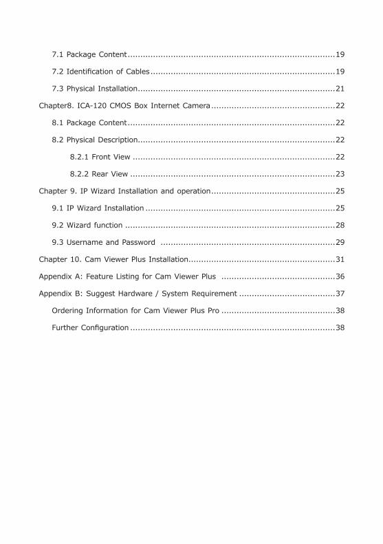
Table of Contents
Chapter 1. Introduction .................................................................................... 3
1.1 Before Installation ................................................................................. 3
Chapter 2. IVS-110 – 1-Channel Internet Video Server ....................................... 4
2.1 Package Content ................................................................................... 4
2.2 Physical Installation ............................................................................. 4
2.2.1 Front Panel ................................................................................. 4
2.2.2 Back Panel ................................................................................. 5
2.2.3 Installation Steps ........................................................................ 6
Chapter 3. ICA-310 – 30M Infrared Internet Camera .......................................... 7
3.1 Package Content ................................................................................... 7
3.2 Physical Installation ............................................................................... 7
Chapter 4. ICA-312 – 25M Infrared Internet Camera .......................................... 9
4.1 Package Content ................................................................................... 9
4.2 Physical Details ..................................................................................... 9
4.3 Hardware Installation ...........................................................................10
Chapter 5. ICA-350 – 30M Infrared Internet Camera .........................................12
5.1 Package Content ..................................................................................12
5.2 Physical Details ....................................................................................12
5.3 Hardware Installation ...........................................................................13
Chapter 6. ICA-525 – 20M IR Vandal Proof Dome Internet Camera .....................14
6.1 Package Content ..................................................................................14
6.2 Identification of Cables .........................................................................14
6.3 Physical Installation ..............................................................................16
Chapter 7. ICA-530 – 15M IR Dome Internet Camera ........................................19
7.1 Package Content ..................................................................................19
7.2 Identification of Cables .........................................................................19
7.3 Physical Installation ..............................................................................21
Chapter8. ICA-120 CMOS Box Internet Camera .................................................22
8.1 Package Content ..................................................................................22
8.2 Physical Description..............................................................................22
8.2.1 Front View ................................................................................22
8.2.2 Rear View .................................................................................23
Chapter 9. IP Wizard Installation and operation .................................................25
9.1 IP Wizard Installation ...........................................................................25
9.2 Wizard function ...................................................................................28
9.3 Username and Password .....................................................................29
Chapter 10. Cam Viewer Plus Installation ..........................................................31
Appendix A: Feature Listing for Cam Viewer Plus .............................................36
Appendix B: Suggest Hardware / System Requirement ......................................37
Ordering Information for Cam Viewer Plus Pro .............................................38
Further Configuration .................................................................................38
�
Chapter 1. IntroductionThank you for purchasing the IP surveillance product. It is versatile and high image solution of the perfect indoor / outdoor surveillance application. The IP surveillance state-of-art design is considerable to fit in various network environments.
1.1 Before InstallationBefore installation, please be sure to read this quick installation guide and user’s manual (CD) carefully to complete machine installation.
This QIG includes the following chapter:
• Chapter 2. IVS-110 – 1-Channel Internet Video Server
• Chapter 3. ICA-310 – 30M Infrared Internet Camera
• Chapter 4. ICA-312 – 25M Infrared Internet Camera
• Chapter 5. ICA-350 – 30M Infrared Internet Camera
• Chapter 6. ICA-525 – 20M IR Vandal Proof Dome Internet Camera
• Chapter 7. ICA-530 – 15M IR Dome Internet Camera
• Chapter 8. ICA-120 – CMOS Box Internet Camera
• Chapter 9. Initial Utility Installation and operation
• Chapter 10. Cam Viewer Plus Installation
• Appendix A: Feature Listing for Cam Viewer Plus
• Appendix B: Suggest Hardware / System Requirement
�
Chapter 2. IVS-110 – 1-Channel Internet Video Server2.1 Package ContentIVS-110 x 1
Power Adapter x 1
Power Cable x 1
CD Disk x 1
Quick Installation Guide x 1
Note
1. If any of the above items are missing, please contact your dealer immediately.
2. Using a power supply with a different voltage that the one included with the IVS-110 will cause damage and void the warranty for IVS-110.
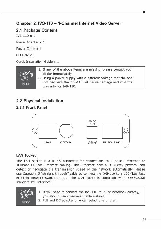
2.2 Physical Installation 2.2.1 Front Panel
LAN Socket
The LAN socket is a RJ-45 connector for connections to 10Base-T Ethernet or 100Base-TX Fast Ethernet cabling. This Ethernet port built N-Way protocol can detect or negotiate the transmission speed of the network automatically. Please use Category 5 “straight through” cable to connect the IVS-110 to a 100Mbps Fast Ethernet network switch or hub. The LAN socket is compliant with IEEE802.3af standard PoE interface.
Note
1. If you need to connect the IVS-110 to PC or notebook directly, you should use cross over cable instead.
2. PoE and DC adapter only can select one of them
�
Video-in Jack
You can install an analog camera and connect it to video-in jack.
12V DC-Out Jack
The output power is 12V DC. This is used to supply 12V DC power to one external camera. The output power is 12V DC, 400mA maximum. The output power still supplies 12 V DC, 400mA power to one external, when the IVS-110 obtains power from PoE switch.
DI/DO/RS-485 Connector
This IVS-110 provides a general I/O terminal block with one digital input and one output for device control. It has 6 Pins that from left to right that are 12V DC power supply (50mA maximum), Alarm Input, GND, Alarm Output, D+ terminal of RS-485 and D- terminal of RS-485.
Note
The RS-485 of IVS-110 is master that can control external scanner or PT camera.
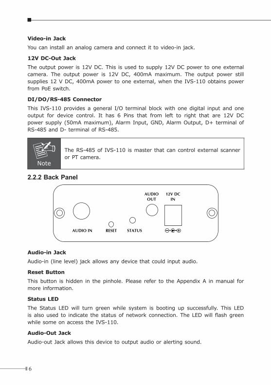
2.2.2 Back Panel
Audio-in Jack
Audio-in (line level) jack allows any device that could input audio.
Reset Button
This button is hidden in the pinhole. Please refer to the Appendix A in manual for more information.
Status LED
The Status LED will turn green while system is booting up successfully. This LED is also used to indicate the status of network connection. The LED will flash green while some on access the IVS-110.
Audio-Out Jack
Audio-out Jack allows this device to output audio or alerting sound.
�
12V DC-in Jack
The input power is 12V DC.
Note
Only use the power adapter supplied with IVS-110. Otherwise, the product may be damaged.
2.2.3 Installation Steps1. Attach video source to IVS-110
To use IVS-110, user must supply video source to IVS-110. Connect the BNC terminal of camera to the IVS-110’s video input and make sure to power on camera first.
2. Attach Audio source to IVS-110 (option)
If user needs not only video stream but also audio stream, then the audio source should be attached to IVS-110. Connect the RCA terminal of audio device’s line output to the IVS-110’s RCA input and make sure to power on your camera or audio device first.
3. Plug an Ethernet cable into IVS-110
Connect an Ethernet cable to the LAN socket located on the IVS-110’s panel and attach it to the network. If there has a PoE switch in your network, you can connect the IVS-110 LAN cable to this PoE switch to obtain power. The power adapter is unnecessary when IVS-110 is connected to a PoE switch.
4. Connect RS-485 (option)
When users would like to apply a camera with P/T/Z function, they usually need to connect their communication port (for camera control) through RS-485. After RS-485 was correctly connected to D+ and D-, the remote users could control the camera movement through internet.
5. Connect the external power supply to IVS-110
Plug in power adapter and connect to power source. If there has a PoE switch in your network, you can connect the IVS-110 LAN cable to this PoE switch to obtain power. The power adapter is unnecessary when IVS-110 is connected to a PoE switch. After power on, IVS-110 will start to operate. Once you have installed the IVS-110 well, the status LED will turn green. It means the system is booting up successfully. Furthermore, if you have a proper network connec-tion, and access to the IVS-110, the LED will flash green.
6. Connect the power supply to one external camera (option)
The IVS-110 can provide 12V DC out to supply one external camera. The output current is 400mA maximum.
�
Chapter 3. ICA-310 – 30M Infrared Internet Camera3.1 Package ContentICA-310 x 1
Power Adapter x 1
Wall Mount Accessories x 1
CD Disk x 1
Quick Installation Guide x 1
Note
1. if any of the above items are missing, please contact your dealer immediately.
2. Using a power supply with a different voltage that the one included with the ICA-310 will cause damage and void the warranty for ICA-310.
3.2 Physical Installation1. Connect an Ethernet cable
Connect the LAN cable on the ICA-310 to the network device (hub or switch).
Note
In case you need to connect the device to PC or notebook directly, you should use cross over cable instead.
2. Connect the power source
Please connect the provided power adapter to ICA-310 power connector and connect the power plug to power outlet. If there is 802.3af PoE switches in your network, you can connect the ICA-310 LAN cable to this PoE switch to obtain power. The power adapter is unnecessary when ICA-310 is connected to a PoE switch.
Note
PoE and DC adapter only can select one of them
�
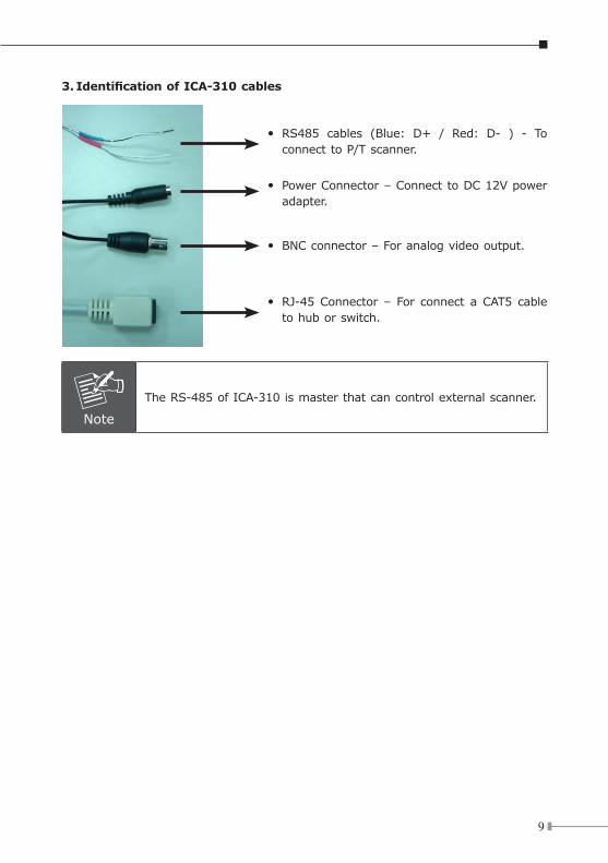
3.IdentificationofICA-310cables
RS485 cables (Blue: D+ / Red: D- ) - To connect to P/T scanner.
Power Connector – Connect to DC 12V power adapter.
BNC connector – For analog video output.
RJ-45 Connector – For connect a CAT5 cable to hub or switch.
ó
ó
ó
ó
Note
The RS-485 of ICA-310 is master that can control external scanner.
10
Chapter 4. ICA-312 – 25M Infrared Internet Camera4.1 Package ContentICA-312 x 1
Power Adapter x 1
Wall Mount Accessories x 1
CD Disk x 1
Quick Installation Guide x 1
Note
1. if any of the above items are missing, please contact your dealer immediately.
2. Using a power supply with a different voltage that the one included with the ICA-312 will cause damage and void the warranty for ICA-312.
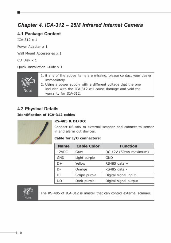
4.2 Physical DetailsIdentificationofICA-312cables
RS-485 & DI/DO:
Connect RS-485 to external scanner and connect to sensor in and alarm out devices.
CableforI/Oconnectors:
Name Cable Color Function
12VDC Gray DC 12V (50mA maximum)
GND Light purple GND
D+ Yellow RS485 data +
D- Orange RS485 data -
DI Stripe purple Digital signal input
DO Dark purple Digital signal output
Note
The RS-485 of ICA-312 is master that can control external scanner.
11
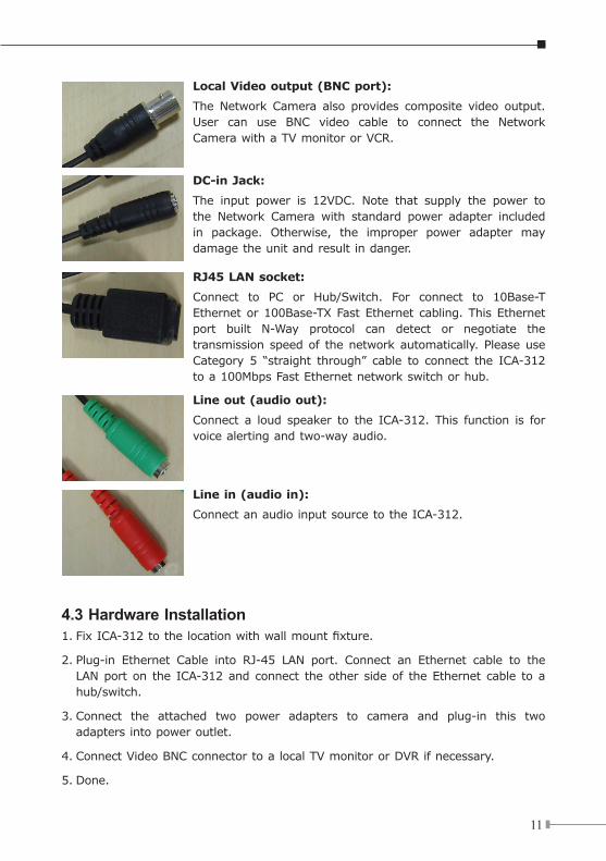
Local Video output (BNC port):
The Network Camera also provides composite video output. User can use BNC video cable to connect the Network Camera with a TV monitor or VCR.
DC-in Jack:
The input power is 12VDC. Note that supply the power to the Network Camera with standard power adapter included in package. Otherwise, the improper power adapter may damage the unit and result in danger.
RJ45 LAN socket:
Connect to PC or Hub/Switch. For connect to 10Base-T Ethernet or 100Base-TX Fast Ethernet cabling. This Ethernet port built N-Way protocol can detect or negotiate the transmission speed of the network automatically. Please use Category 5 “straight through” cable to connect the ICA-312 to a 100Mbps Fast Ethernet network switch or hub.
Line out (audio out):
Connect a loud speaker to the ICA-312. This function is for voice alerting and two-way audio.
Line in (audio in):
Connect an audio input source to the ICA-312.
4.3 Hardware Installation1. Fix ICA-312 to the location with wall mount fixture.
2. Plug-in Ethernet Cable into RJ-45 LAN port. Connect an Ethernet cable to the LAN port on the ICA-312 and connect the other side of the Ethernet cable to a hub/switch.
3. Connect the attached two power adapters to camera and plug-in this two adapters into power outlet.
4. Connect Video BNC connector to a local TV monitor or DVR if necessary.
5. Done.
12
Chapter 5. ICA-350 – 30M Infrared Internet Camera5.1 Package ContentICA-350 x 1
Power Adapter x 2 (one for ICA-350, another for heater)
Wall Mount Accessories x 1
CD Disk x 1
Quick Installation Guide x 1
Screws with plastic washer x 2
Minor pad x 1
L wrench x 1
Note
1. if any of the above items are missing, please contact your dealer immediately.
2. Using a power supply with a different voltage that the one included with the ICA-350 will cause damage and void the warranty for ICA-350.
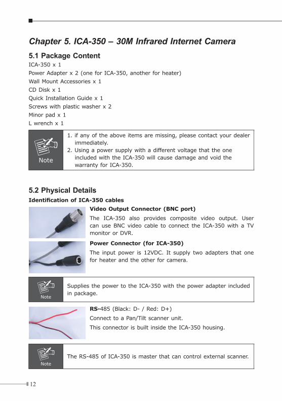
5.2 Physical DetailsIdentificationofICA-350cables
Video Output Connector (BNC port)
The ICA-350 also provides composite video output. User can use BNC video cable to connect the ICA-350 with a TV monitor or DVR.
PowerConnector(forICA-350)
The input power is 12VDC. It supply two adapters that one for heater and the other for camera.
Note
Supplies the power to the ICA-350 with the power adapter included in package.
RS-485 (Black: D- / Red: D+)
Connect to a Pan/Tilt scanner unit.
This connector is built inside the ICA-350 housing.
Note
The RS-485 of ICA-350 is master that can control external scanner.
13
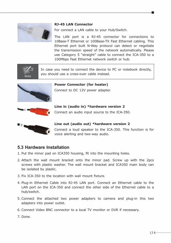
RJ-45 LAN Connector
For connect a LAN cable to your Hub/Switch.
The LAN port is a RJ-45 connector for connections to 10Base-T Ethernet or 100Base-TX Fast Ethernet cabling. This Ethernet port built N-Way protocol can detect or negotiate the transmission speed of the network automatically. Please use Category 5 “straight” cable to connect the ICA-350 to a 100Mbps Fast Ethernet network switch or hub.
Note
In case you need to connect the device to PC or notebook directly, you should use a cross-over cable instead.
PowerConnector(forheater)
Connect to DC 12V power adapter.
Line in (audio in) *hardware version 2
Connect an audio input source to the ICA-350.
Line out (audio out) *hardware version 2
Connect a loud speaker to the ICA-350. This function is for voice alerting and two-way audio.
5.3 Hardware Installation1. Put the minor pad on ICA350 housing, fit into the mounting holes.
2. Attach the wall mount bracket onto the minor pad. Screw up with the 2pcs screws with plastic washer. The wall mount bracket and ICA350 main body can be isolated by plastic.
3. Fix ICA-350 to the location with wall mount fixture.
4. Plug-in Ethernet Cable into RJ-45 LAN port. Connect an Ethernet cable to the LAN port on the ICA-350 and connect the other side of the Ethernet cable to a hub/switch.
5. Connect the attached two power adapters to camera and plug-in this two adapters into power outlet.
6. Connect Video BNC connector to a local TV monitor or DVR if necessary.
7. Done.
1�
Chapter 6. ICA-525 – 20M IR Vandal Proof Dome Internet Camera
6.1 Package ContentICA-525 x 1
Power Adapter x 1
Screws x 4
Telephone box x 1
L-Wrench x 1
CD Disk x 1
Quick Installation Guide x 1
Note
1. if any of the above items are missing, please contact your dealer immediately.
2. Using a power supply with a different voltage that the one included with the ICA-525 will cause damage and void the warranty for ICA-525.
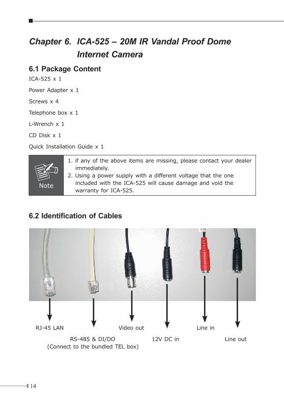
6.2 Identification of Cables
RJ-45 LAN Video out Line in
RS-485 & DI/DO 12V DC in Line out (Connect to the bundled TEL box)
1�
1. RJ-45 LAN socket: Connect to PC or Hub/Switch. For connect to 10Base-T Ethernet or 100Base-TX Fast Ethernet cabling. This Ethernet port built N-Way protocol can detect or negotiate the transmission speed of the network auto-matically. Please use Category 5 “straight through” cable to connect the ICA-525 to a 100Mbps Fast Ethernet network switch or hub.
Note
In case you need to connect the device to PC or notebook directly, you should use cross over cable instead.
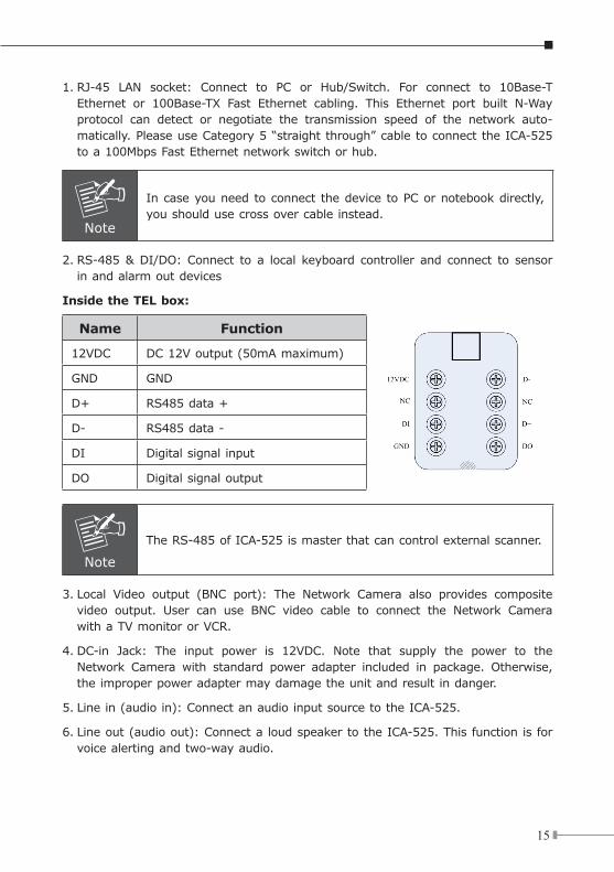
2. RS-485 & DI/DO: Connect to a local keyboard controller and connect to sensor in and alarm out devices
Inside the TEL box:
Name Function
12VDC DC 12V output (50mA maximum)
GND GND
D+ RS485 data +
D- RS485 data -
DI Digital signal input
DO Digital signal output
Note
The RS-485 of ICA-525 is master that can control external scanner.
3. Local Video output (BNC port): The Network Camera also provides composite video output. User can use BNC video cable to connect the Network Camera with a TV monitor or VCR.
4. DC-in Jack: The input power is 12VDC. Note that supply the power to the Network Camera with standard power adapter included in package. Otherwise, the improper power adapter may damage the unit and result in danger.
5. Line in (audio in): Connect an audio input source to the ICA-525.
6. Line out (audio out): Connect a loud speaker to the ICA-525. This function is for voice alerting and two-way audio.
1�
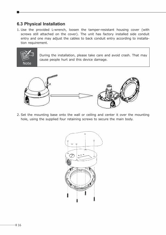
6.3 Physical Installation1. Use the provided L-wrench, loosen the tamper-resistant housing cover (with
screws still attached on the cover). The unit has factory installed side conduit entry and one may adjust the cables to back conduit entry according to installa-tion requirement.
Note
During the installation, please take care and avoid crash. That may cause people hurt and this device damage.
2. Set the mounting base onto the wall or ceiling and center it over the mounting hole, using the supplied four retaining screws to secure the main body.
1�
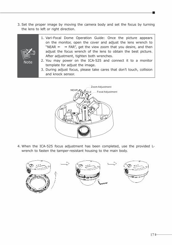
3. Set the proper image by moving the camera body and set the focus by turning the lens to left or right direction.
Note
1. Vari-Focal Dome Operation Guide: Once the picture appears on the monitor, open the cover and adjust the lens wrench to “NEAR © ™ FAR”, get the view zoom that you desire, and then adjust the focus wrench of the lens to obtain the best picture. After adjustment, tighten both wrenches.
2. You may power on the ICA-525 and connect it to a monitor template for adjust the image.
3. During adjust focus, please take cares that don’t touch, collision and knock sensor.
Zoom Adjustment
Focal AdjustmentNEAR
FARWIDE
TELE
4. When the ICA-525 focus adjustment has been completed, use the provided L-wrench to fasten the tamper-resistant housing to the main body.
1�
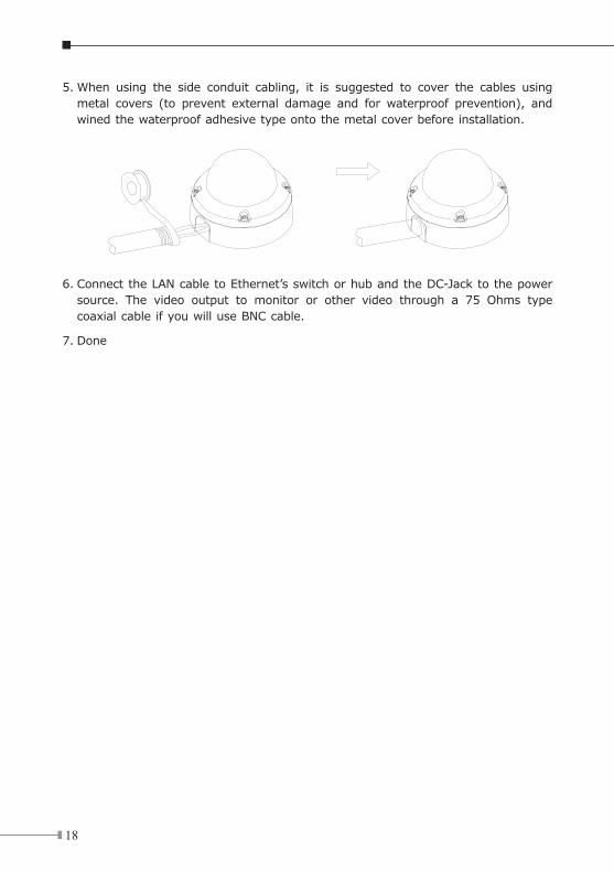
5. When using the side conduit cabling, it is suggested to cover the cables using metal covers (to prevent external damage and for waterproof prevention), and wined the waterproof adhesive type onto the metal cover before installation.
6. Connect the LAN cable to Ethernet’s switch or hub and the DC-Jack to the power source. The video output to monitor or other video through a 75 Ohms type coaxial cable if you will use BNC cable.
7. Done
1�
Chapter 7. ICA-530 – 15M IR Dome Internet Camera7.1 Package ContentICA-530 x 1
Power Adapter x 1
Wrench x 1
Telephone box x 1
CD Disk x 1
Quick Installation Guide x 1
Note
1. if any of the above items are missing, please contact your dealer immediately.
2. Using a power supply with a different voltage that the one included with the ICA-530 will cause damage and void the warranty for ICA-530.
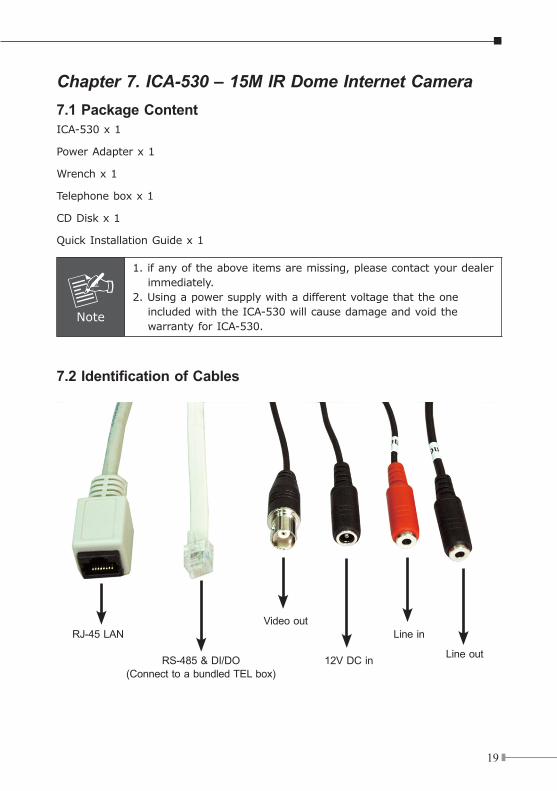
7.2 Identification of Cables
RJ-45 LANVideo out
Line in
RS-485 & DI/DO(Connect to a bundled TEL box)
Line out12V DC in
20
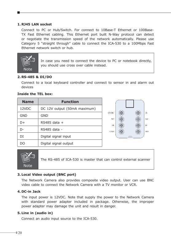
1. RJ45 LAN socket
Connect to PC or Hub/Switch. For connect to 10Base-T Ethernet or 100Base-TX Fast Ethernet cabling. This Ethernet port built N-Way protocol can detect or negotiate the transmission speed of the network automatically. Please use Category 5 “straight through” cable to connect the ICA-530 to a 100Mbps Fast Ethernet network switch or hub.
Note
In case you need to connect the device to PC or notebook directly, you should use cross over cable instead.
2. RS-485 & DI/DO
Connect to a local keyboard controller and connect to sensor in and alarm out devices
Inside the TEL box:
Name Function
12VDC DC 12V output (50mA maximum)
GND GND
D+ RS485 data +
D- RS485 data -
DI Digital signal input
DO Digital signal output
Note
The RS-485 of ICA-530 is master that can control external scanner
3. Local Video output (BNC port)
The Network Camera also provides composite video output. User can use BNC video cable to connect the Network Camera with a TV monitor or VCR.
4. DC-in Jack
The input power is 12VDC. Note that supply the power to the Network Camera with standard power adapter included in package. Otherwise, the improper power adapter may damage the unit and result in danger.
5. Line in (audio in)
Connect an audio input source to the ICA-530.
21
6. Line out (audio out)
Connect a loud speaker to the ICA-530. This function is for voice alerting and two-way audio.
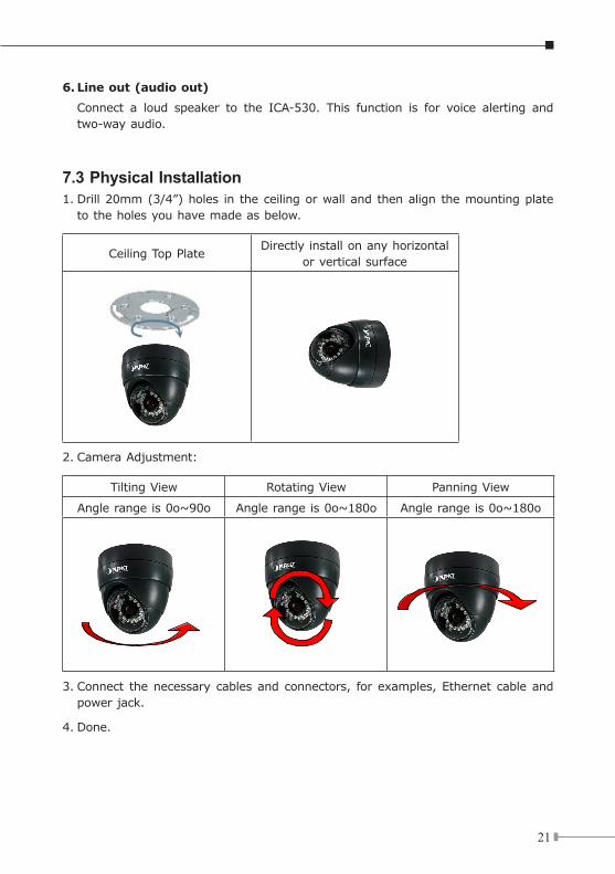
7.3 Physical Installation1. Drill 20mm (3/4”) holes in the ceiling or wall and then align the mounting plate
to the holes you have made as below.
Ceiling Top PlateDirectly install on any horizontal
or vertical surface
2. Camera Adjustment:
Tilting View Rotating View Panning View
Angle range is 0o~90o Angle range is 0o~180o Angle range is 0o~180o
3. Connect the necessary cables and connectors, for examples, Ethernet cable and power jack.
4. Done.
22
Chapter8. ICA-120 CMOS Box Internet Camera8.1 Package ContentICA-120 x 1
Power Adapter x 1
Camera Mount Kit x 1
CD Disk x 1
Quick Installation Guide x 1
Note
1. If any of the above items are missing, please contact your dealer immediately.
2. Using a power supply with a different voltage that the one included with the ICA-120 will cause damage and void the warranty for ICA-120.
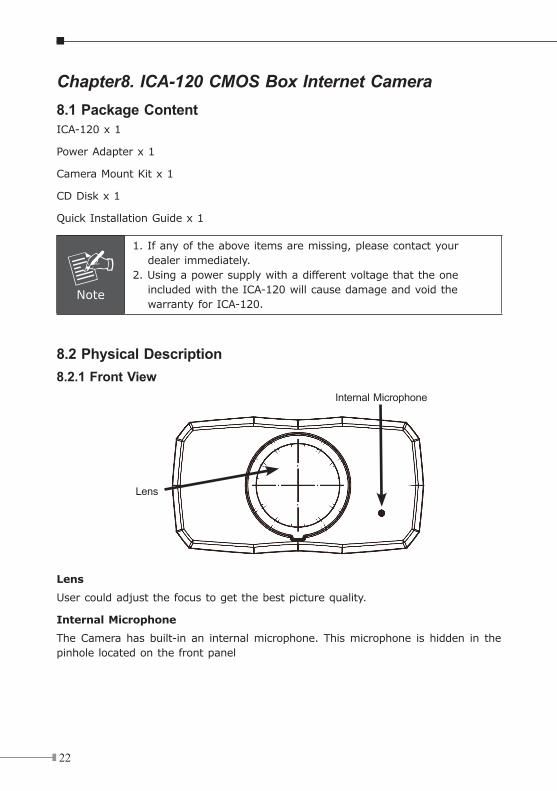
8.2 Physical Description8.2.1 Front View
Internal Microphone
Lens
Lens
User could adjust the focus to get the best picture quality.
Internal Microphone
The Camera has built-in an internal microphone. This microphone is hidden in the pinhole located on the front panel
23
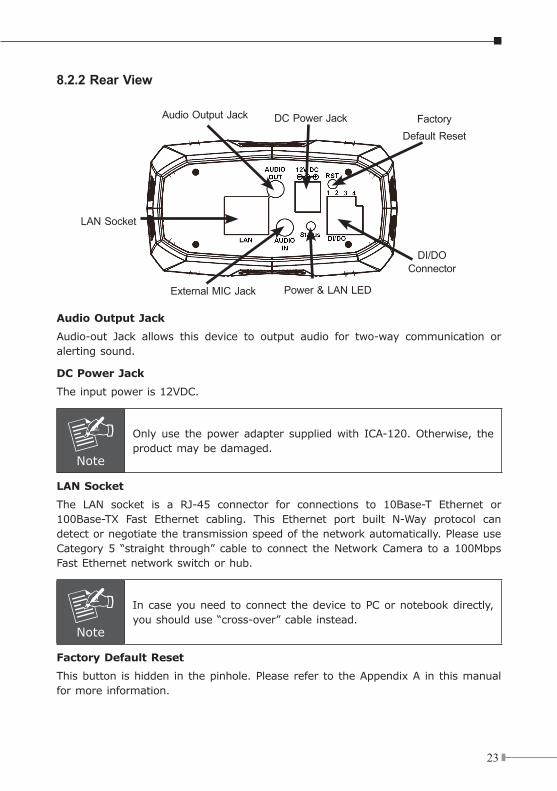
8.2.2 Rear View
DI/DO Connector
FactoryDefault Reset
DC Power JackAudio Output Jack
LAN Socket
External MIC Jack Power & LAN LED
Audio Output Jack
Audio-out Jack allows this device to output audio for two-way communication or alerting sound.
DC Power Jack
The input power is 12VDC.
Note
Only use the power adapter supplied with ICA-120. Otherwise, the product may be damaged.
LAN Socket
The LAN socket is a RJ-45 connector for connections to 10Base-T Ethernet or 100Base-TX Fast Ethernet cabling. This Ethernet port built N-Way protocol can detect or negotiate the transmission speed of the network automatically. Please use Category 5 “straight through” cable to connect the Network Camera to a 100Mbps Fast Ethernet network switch or hub.
Note
In case you need to connect the device to PC or notebook directly, you should use “cross-over” cable instead.
FactoryDefaultReset
This button is hidden in the pinhole. Please refer to the Appendix A in this manual for more information.

2�
Power & LAN LED (green color)
This LED is used to indicate whether DC power is on or not. In addition, this LED will be flashing while network accessing via Ethernet.
DI/DO Connector
The Camera provides a terminal block with 4 pins of connectors for DI and DO. Please refer to the Appendix B in this manual for more information.
External Microphone
The Camera also supports external microphone. User can plug in an external microphone to pick up voice more.
2�
Chapter 9. IP Wizard Installation and operationThis chapter shows how to quick set up your IP surveillance product. The IP surveillance product is with the default settings. However to help you find the networked camera quickly the windows utility-IP Wizard can search the cameras in the network that shall help you to configure some basic setting before you started advanced management and monitoring.
9.1 IP Wizard Installation
Note
In the installation steps below, this guide use ICA-310 as the example. However, the steps for ICA-312/350/525/530 & IVS-110 are similar.
1. Insert the bundled CD into the CD-ROM drive to launch the autorun program. Once completed, a welcome menu screen will appear.
2. Select the click the model name on the web page.
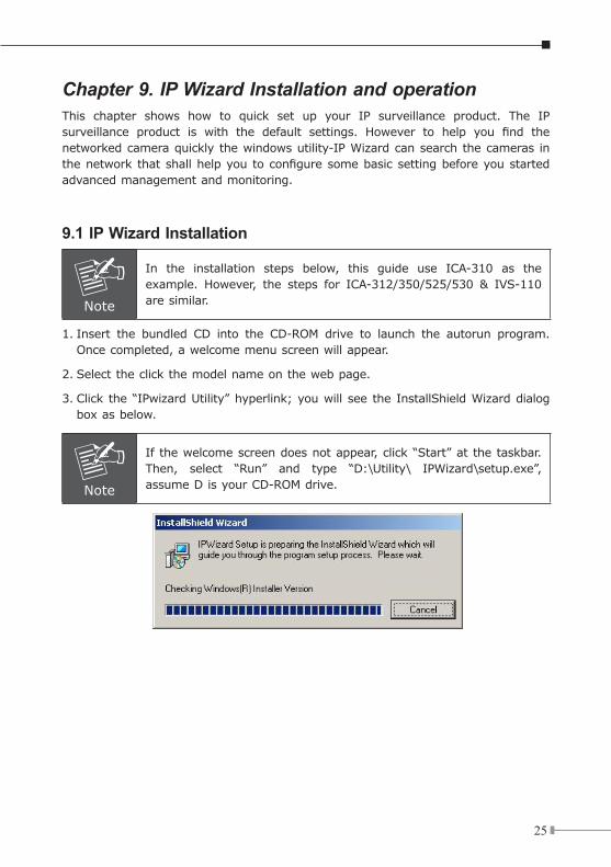
3. Click the “IPwizard Utility” hyperlink; you will see the InstallShield Wizard dialog box as below.
Note
If the welcome screen does not appear, click “Start” at the taskbar. Then, select “Run” and type “D:\Utility\ IPWizard\setup.exe”, assume D is your CD-ROM drive.
2�
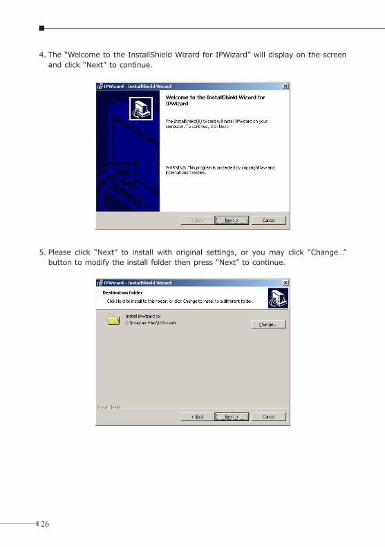
4. The “Welcome to the InstallShield Wizard for IPWizard” will display on the screen and click “Next” to continue.
5. Please click “Next” to install with original settings, or you may click “Change…” button to modify the install folder then press “Next” to continue.
2�
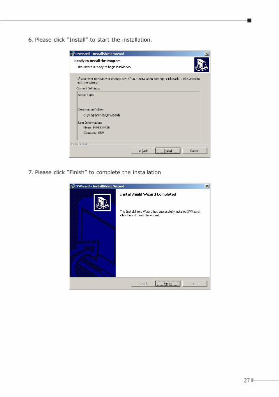
6. Please click “Install” to start the installation.
7. Please click “Finish” to complete the installation
2�
8. Please double-click the utility icon on the desktop then you will see the utility.
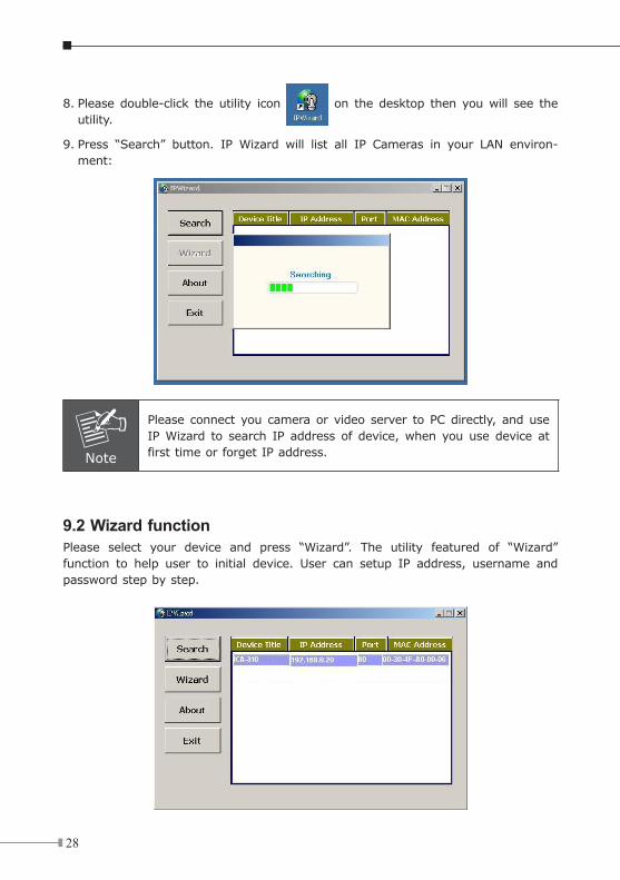
9. Press “Search” button. IP Wizard will list all IP Cameras in your LAN environ-ment:
Note
Please connect you camera or video server to PC directly, and use IP Wizard to search IP address of device, when you use device at first time or forget IP address.
9.2 Wizard functionPlease select your device and press “Wizard”. The utility featured of “Wizard” function to help user to initial device. User can setup IP address, username and password step by step.
2�
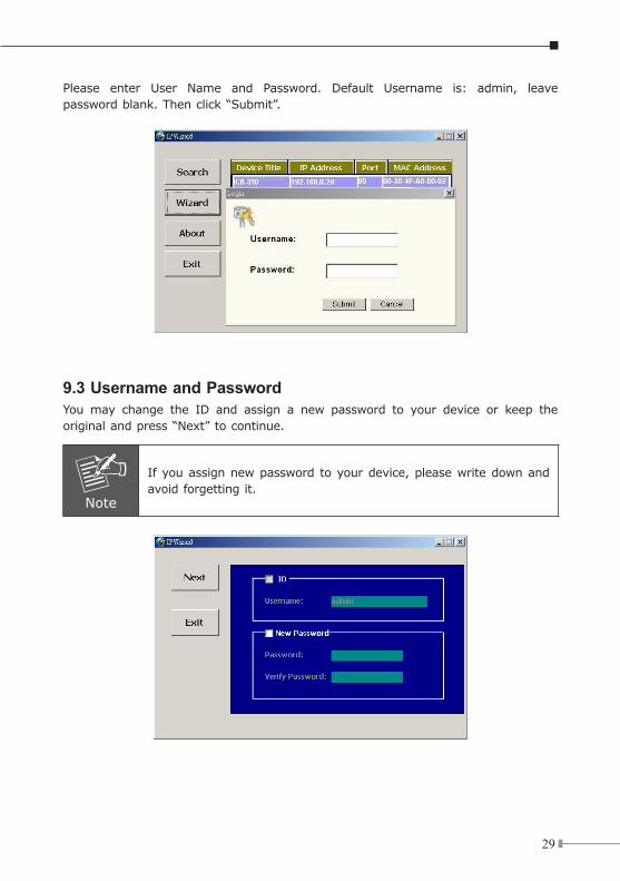
Please enter User Name and Password. Default Username is: admin, leave password blank. Then click “Submit”.
9.3 Username and Password You may change the ID and assign a new password to your device or keep the original and press “Next” to continue.
Note
If you assign new password to your device, please write down and avoid forgetting it.
30
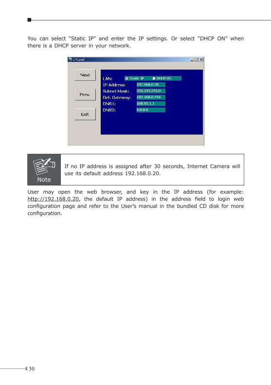
You can select “Static IP” and enter the IP settings. Or select “DHCP ON” when there is a DHCP server in your network.
Note
If no IP address is assigned after 30 seconds, Internet Camera will use its default address 192.168.0.20.
User may open the web browser, and key in the IP address (for example: http://192.168.0.20, the default IP address) in the address field to login web configuration page and refer to the User’s manual in the bundled CD disk for more configuration.
31
Chapter 10. Cam Viewer Plus Installation
Note
The Cam Viewer Plus Pro 30 days trial version installation steps are similar. Below is the installation of Cam Viewer Plus.
Insert the bundled CD disk into the CD-ROM drive to launch the autorun program. Once completed, a welcome menu screen will appear. Click the “Cam Viewer Plus” hyperlink, the below InstallShield Wizard dialog box will appear.
Note
If the welcome screen does not appear, click “Start” at the taskbar. Then, select “Run” and type “D:\Utility\Cam Viewer Plus\setup.exe”, assume “D” is your CD-ROM drive.
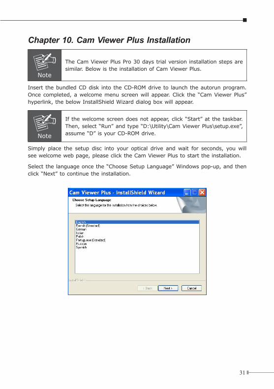
Simply place the setup disc into your optical drive and wait for seconds, you will see welcome web page, please click the Cam Viewer Plus to start the installation.
Select the language once the “Choose Setup Language” Windows pop-up, and then click “Next” to continue the installation.
32
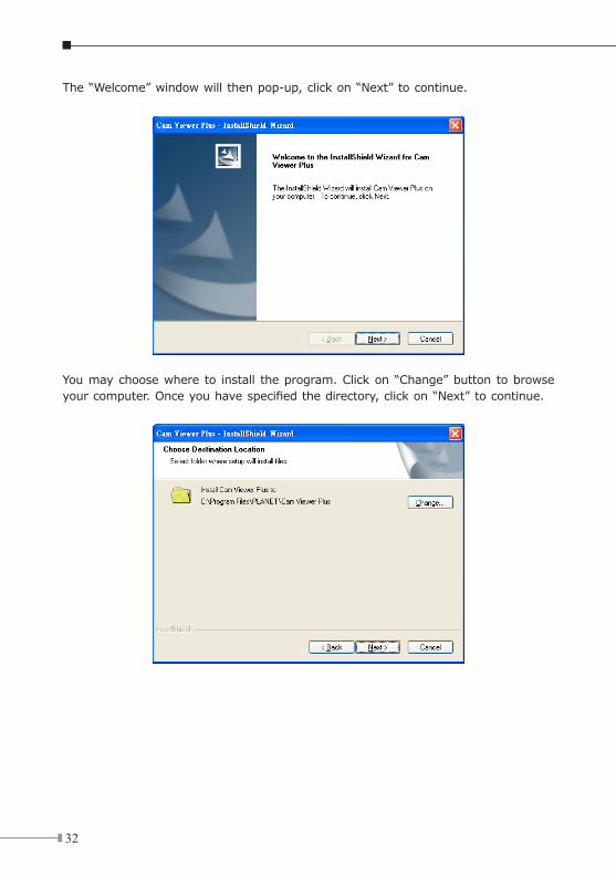
The “Welcome” window will then pop-up, click on “Next” to continue.
You may choose where to install the program. Click on “Change” button to browse your computer. Once you have specified the directory, click on “Next” to continue.
33
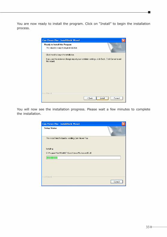
You are now ready to install the program. Click on “Install” to begin the installation process.
You will now see the installation progress. Please wait a few minutes to complete the installation.
3�
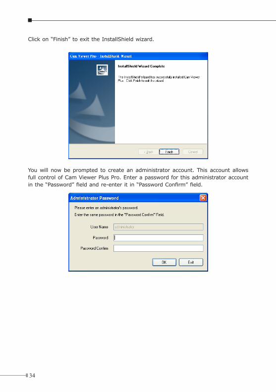
Click on “Finish” to exit the InstallShield wizard.
You will now be prompted to create an administrator account. This account allows full control of Cam Viewer Plus Pro. Enter a password for this administrator account in the “Password” field and re-enter it in “Password Confirm” field.
3�
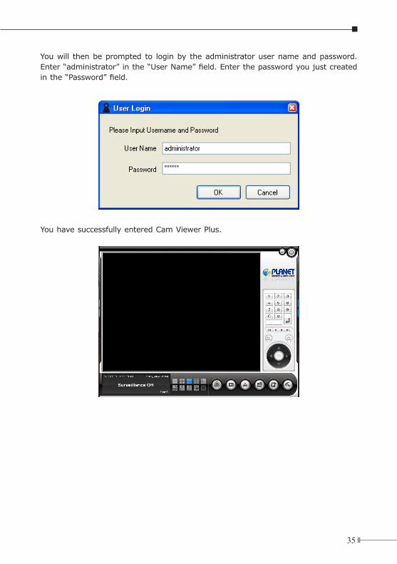
You will then be prompted to login by the administrator user name and password. Enter “administrator” in the “User Name” field. Enter the password you just created in the “Password” field.
You have successfully entered Cam Viewer Plus.
3�
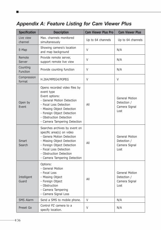
Appendix A: Feature Listing for Cam Viewer PlusSpecification Description Cam Viewer Plus Pro Cam Viewer Plus
Live view channel
Max. channels monitored simultaneously
Up to 64 channels Up to 64 channels
E-MapShowing camera's location and map background
V N/A
Remote Server
Provide remote server, support remote live view
V N/A
Counting Function
Provide counting function V N/A
Compression format
H.264/MPEG4/MJPEG V V
Open by Event
Opens recorded video files by event typeEvent options:- General Motion Detection- Focal Loss Detection- Missing Object Detection- Foreign Object Detection- Obstruction Detection- Camera Tampering Detection
All
General Motion Detection /Camera Signal Lost
Smart Search
Searches archives by event on specific area(s) on video- Genera Motion Detection- Missing Object Detection- Foreign Object Detection- Focal Loss Detection- Obstruction Detection- Camera Tampering Detection
All
General Motion Detection /Camera Signal Lost
Intelligent Guard
Options: - General Motion- Focal Loss- Missing Object- Foreign Object- Obstruction- Camera Tampering- Camera Signal Loss
All
General Motion Detection /Camera Signal Lost
SMS Alarm Send a SMS to mobile phone. V N/A
Preset GoControl PZ camera to a specify location.
V N/A
3�
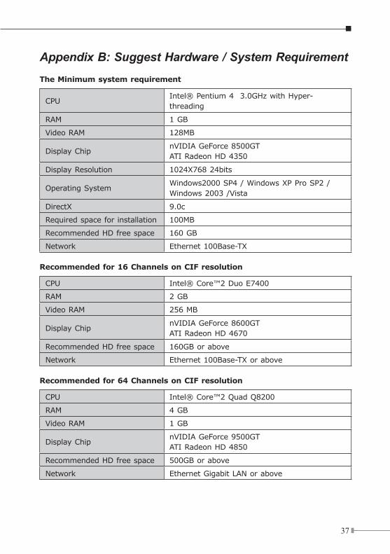
Appendix B: Suggest Hardware / System RequirementThe Minimum system requirement
CPUIntel® Pentium 4 3.0GHz with Hyper-threading
RAM 1 GB
Video RAM 128MB
Display ChipnVIDIA GeForce 8500GTATI Radeon HD 4350
Display Resolution 1024X768 24bits
Operating SystemWindows2000 SP4 / Windows XP Pro SP2 /Windows 2003 /Vista
DirectX 9.0c
Required space for installation 100MB
Recommended HD free space 160 GB
Network Ethernet 100Base-TX
Recommendedfor16ChannelsonCIFresolution
CPU Intel® Core™2 Duo E7400
RAM 2 GB
Video RAM 256 MB
Display ChipnVIDIA GeForce 8600GTATI Radeon HD 4670
Recommended HD free space 160GB or above
Network Ethernet 100Base-TX or above
Recommendedfor64ChannelsonCIFresolution
CPU Intel® Core™2 Quad Q8200
RAM 4 GB
Video RAM 1 GB
Display ChipnVIDIA GeForce 9500GTATI Radeon HD 4850
Recommended HD free space 500GB or above
Network Ethernet Gigabit LAN or above
3�
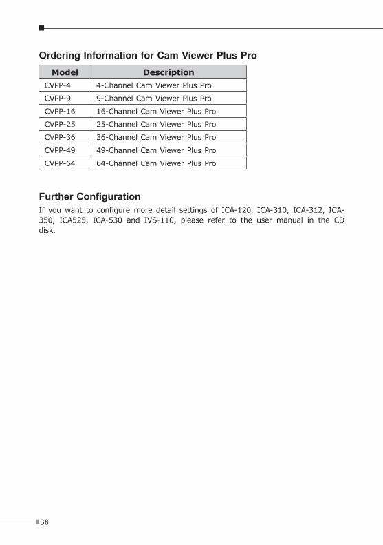
Ordering Information for Cam Viewer Plus ProModel Description
CVPP-4 4-Channel Cam Viewer Plus Pro
CVPP-9 9-Channel Cam Viewer Plus Pro
CVPP-16 16-Channel Cam Viewer Plus Pro
CVPP-25 25-Channel Cam Viewer Plus Pro
CVPP-36 36-Channel Cam Viewer Plus Pro
CVPP-49 49-Channel Cam Viewer Plus Pro
CVPP-64 64-Channel Cam Viewer Plus Pro
Further ConfigurationIf you want to configure more detail settings of ICA-120, ICA-310, ICA-312, ICA-350, ICA525, ICA-530 and IVS-110, please refer to the user manual in the CD disk.

This page is intentionally left blank

This page is intentionally left blank