internet-draft sami boutros - datatracker.ietf.org · internet draft evpn control plane for geneve...
TRANSCRIPT

INTERNET-DRAFT Sami BoutrosIntended Status: Standard Track VMware Ali Sajassi Cisco Systems John Drake Juniper Networks Jorge Rabadan Nokia
Expires: September 2, 2018 March 1, 2018
EVPN control plane for Geneve draft-boutros-bess-evpn-geneve-02.txt
Abstract
This document describes how Ethernet VPN (EVPN) control plane can be used with Network Virtualization Overlay over Layer 3 (NVO3) Generic Network Virtualization Encapsulation (Geneve) encapsulation for NVO3 solutions. EVPN control plane can also be used by a Network Virtualization Endpoints (NVEs) to express Geneve tunnel option TLV(s)supported in transmission and/or reception of Geneve encapsulated data packets.
Status of this Memo
This Internet-Draft is submitted to IETF in full conformance with the provisions of BCP 78 and BCP 79.
Internet-Drafts are working documents of the Internet Engineering Task Force (IETF), its areas, and its working groups. Note that other groups may also distribute working documents as Internet-Drafts.
Internet-Drafts are draft documents valid for a maximum of six months and may be updated, replaced, or obsoleted by other documents at any time. It is inappropriate to use Internet-Drafts as reference material or to cite them other than as "work in progress."
The list of current Internet-Drafts can be accessed at http://www.ietf.org/1id-abstracts.html
The list of Internet-Draft Shadow Directories can be accessed at http://www.ietf.org/shadow.html
Copyright and License Notice
Boutros Expires September 2, 2018 [Page 1]

INTERNET DRAFT EVPN control plane for Geneve March 1, 2018
Copyright (c) 2018 IETF Trust and the persons identified as the document authors. All rights reserved.
This document is subject to BCP 78 and the IETF Trust’s Legal Provisions Relating to IETF Documents (http://trustee.ietf.org/license-info) in effect on the date of publication of this document. Please review these documents carefully, as they describe your rights and restrictions with respect to this document. Code Components extracted from this document must include Simplified BSD License text as described in Section 4.e of the Trust Legal Provisions and are provided without warranty as described in the Simplified BSD License.
Table of Contents
1 Introduction . . . . . . . . . . . . . . . . . . . . . . . . . 3 1.1 Terminology . . . . . . . . . . . . . . . . . . . . . . . . 3 2. GENEVE extensions . . . . . . . . . . . . . . . . . . . . . . . 4 2.1 Ethernet option TLV . . . . . . . . . . . . . . . . . . . . 4 3. BGP Extensions . . . . . . . . . . . . . . . . . . . . . . . . 6 3.1 Geneve Tunnel Option Types sub-TLV . . . . . . . . . . . . . 6 4. Operation . . . . . . . . . . . . . . . . . . . . . . . . . . . 7 5. Security Considerations . . . . . . . . . . . . . . . . . . . . 8 6. IANA Considerations . . . . . . . . . . . . . . . . . . . . . . 8 7. Acknowledgements . . . . . . . . . . . . . . . . . . . . . . . 9 8. References . . . . . . . . . . . . . . . . . . . . . . . . . . 9 8.1 Normative References . . . . . . . . . . . . . . . . . . . . 9 8.2 Informative References . . . . . . . . . . . . . . . . . . 10 Authors’ Addresses . . . . . . . . . . . . . . . . . . . . . . . . 10
Boutros Expires September 2, 2018 [Page 2]

INTERNET DRAFT EVPN control plane for Geneve March 1, 2018
1 Introduction
The Network Virtualization over Layer 3 (NVO3) solutions for network virtualization in data center (DC) environment are based on an IP- based underlay. An NVO3 solution provides layer 2 and/or layer 3 overlay services for virtual networks enabling multi-tenancy and workload mobility. The NVO3 working group have been working on different dataplane encapsulations. The Generic Network Virtualization Encapsulation [GENEVE] have been recently recommended to be the proposed standard for network virtualization overlay encapsulation.
This document describes how the EVPN control plane can signal Geneve encapsulation type in the BGP Tunnel Encapsulation Extended Community defined in [TUNNEL-ENCAP]. In addition, this document defines how to communicate the Geneve tunnel option types in a new BGP Tunnel Encapsulation Attribute sub-TLV. The Geneve tunnel options are encapsulated as TLVs after the Geneve base header in the Geneve packet as described in [GENEVE].
[DT-ENCAP] recommends that a control plane determines how Network Virtualization Edge devices (NVEs) use the GENEVE option TLVs when sending/receiving packets. In particular, the control plane negotiates the subset of option TLVs supported, their order and the total number of option TLVs allowed in the packets. This negotiation capability allows, for example, interoperability with hardware-based NVEs that can process fewer options than software-based NVEs.
This EVPN control plane extension will allow a Network Virtualization Edge (NVE) to express what Geneve option TLV types it is capable to receive or to send over the Geneve tunnel to its peers.
In the datapath, a transmitting NVE MUST NOT encapsulate a packet destined to another NVE with any option TLV(s) the receiving NVE is not capable of processing.
1.1 Terminology
The key words "MUST", "MUST NOT", "REQUIRED", "SHALL", "SHALL NOT", "SHOULD", "SHOULD NOT", "RECOMMENDED", "NOT RECOMMENDED", "MAY", and "OPTIONAL" in this document are to be interpreted as described in BCP 14 [RFC2119] [RFC8174] when, and only when, they appear in all capitals, as shown here.
Most of the terminology used in this documents comes from [RFC7432] and [NVO3-FRWK].
NVO3: Network Virtualization Overlay over Layer 3
Boutros Expires September 2, 2018 [Page 3]

INTERNET DRAFT EVPN control plane for Geneve March 1, 2018
GENEVE: Generic Network Virtualization Encapsulation.
NVE: Network Virtualization Edge.
VNI: Virtual Network Identifier.
MAC: Media Access Control.
OAM: Operations, Administration and Maintenance.
PE: Provide Edge Node.
CE: Customer Edge device e.g., host or router or switch.
EVPN: Ethernet VPN.
EVI: An EVPN instance spanning the Provider Edge (PE) devices participating in that EVPN.
MAC-VRF: A Virtual Routing and Forwarding table for Media Access Control (MAC) addresses on a PE.2. GENEVE extensions
This document adds some extensions to the [GENEVE] encapsulation that are relevant to the operation of EVPN.
2.1 Ethernet option TLV
[EVPN-OVERLAY] describes when an ingress NVE uses ingress replication to flood unknown unicast traffic to the egress NVEs, the ingress NVE needs to indicate to the egress NVE that the Encapsulated packet is a BUM traffic type. This is required to avoid transient packet duplication in all-active multi-homing scenarios. For GENVE encapsulation we need a bit to for this purpose.
[RFC8317] uses MPLS label for leaf indication of BUM traffic originated from a leaf AC in an ingress NVE so that the egress NVEs can filter BUM traffic toward their leaf ACs. For GENVE encapsulation we need a bit for this purpose.
Although the default mechanism for split-horizon filtering of BUM traffic on an Ethernet segment for IP-based ecnapsulations such as VxLAN, GPE, NVGRE, and GENVE, is local-bias as defined in section 8.3.1 of [EVPN-OVERLAY], there can be an incentive to leverage the same split-horizon filtering mechanism of [RFC7432] that uses a 20- bit MPLS label so that a) the a single filtering mechanism is used for all encapsulation types and b) the same PE can participate in a mix of MPLS and IP encapsulations. For this purpose a 20-bit label
Boutros Expires September 2, 2018 [Page 4]

INTERNET DRAFT EVPN control plane for Geneve March 1, 2018
field MAY be defined for GENVE encapsulation. The support for this label is optional.
If an NVE wants to use local-bias procedure, then it sends the new option TLV without ESI-label (e.g., length=4): 0 1 2 3 0 1 2 3 4 5 6 7 8 9 0 1 2 3 4 5 6 7 8 9 0 1 2 3 4 5 6 7 8 9 0 1 +-+-+-+-+-+-+-+-+-+-+-+-+-+-+-+-+-+-+-+-+-+-+-+-+-+-+-+-+-+-+-+-+ | Option Class=Ethernet |Type=0 |B|L|R| Len=0x1 | +-+-+-+-+-+-+-+-+-+-+-+-+-+-+-+-+-+-+-+-+-+-+-+-+-+-+-+-+-+-+-+-+
If an NVE wants to use ESI-label, then it sends the new option TLV with ESI-label (e.g., length=8)
0 1 2 3 0 1 2 3 4 5 6 7 8 9 0 1 2 3 4 5 6 7 8 9 0 1 2 3 4 5 6 7 8 9 0 1 +-+-+-+-+-+-+-+-+-+-+-+-+-+-+-+-+-+-+-+-+-+-+-+-+-+-+-+-+-+-+-+-+ | Option Class=Ethernet |Typ=EVPN-OPTION|B|L|R| Len=0x2 | +-+-+-+-+-+-+-+-+-+-+-+-+-+-+-+-+-+-+-+-+-+-+-+-+-+-+-+-+-+-+-+-+ | Rsvd | Source-ID | +-+-+-+-+-+-+-+-+-+-+-+-+-+-+-+-+-+-+-+-+-+-+-+-+-+-+-+-+-+-+-+-+
Where: - Option Class is set to Ethernet (new Option Class requested to IANA) - Type is set to EVPN-OPTION (new type requested to IANA) and C bit must be set. - B bit is set to 1 for BUM traffic. - L bit is set to 1 for Leaf-Indication. - Source-ID is a 24-bit value that encodes the ESI-label value signaled on the EVPN Autodiscovery per-ES routes, as described in [RFC7432] for multi-homing and [RFC8317] for leaf-to-leaf BUM filtering. The ESI-label value is encoded in the high-order 20 bits of the Source-ESI field.
The egress NVEs that make use of ESIs in the data path (because they have a local multi-homed ES or support [RFC8317]) SHOULD advertise their Ethernet A-D per-ES routes along with the Geneve tunnel sub-TLV and in addition to the ESI-label Extended Community. The ingress NVE can then use the Ethernet option-TLV when sending GENEVE packets based on the [RFC7432] and [RFC8317] procedures. The egress NVE will use the Source-ID field in the received packets to make filtering decisions.
Note that [EVPN-OVERLAY] modifies the [RFC7432] split-horizon procedures for NVO3 tunnels using the "local-bias" procedure. "Local-
Boutros Expires September 2, 2018 [Page 5]

INTERNET DRAFT EVPN control plane for Geneve March 1, 2018
bias" relies on tunnel IP source address checks (instead of ESI- labels) to determine whether a packet can be forwarded to a local ES.
While "local-bias" MUST be supported along with GENEVE encapsulation, the use of the Ethernet option-TLV is RECOMMENDED to follow the same procedures used by EVPN MPLS.
An ingress NVE using ingress replication to flood BUM traffic MUST send B=1 in all the GENEVE packets that encapsulate BUM frames. An egress NVE SHOULD determine whether a received packet encapsulates a BUM frame based on the B bit. The use of the B bit is only relevant to GENEVE packets with Protocol Type 0x6558 (Bridged Ethernet).
3. BGP Extensions
As per [EVPN-OVERLAY] the BGP Encapsulation extended community defined in [TUNNEL-ENCAP] is included with all EVPN routes advertised by an egress NVE.
This document specifies a new BGP Tunnel Encapsulation Type for Geneve and a new Geneve tunnel option types sub-TLV as described below.
3.1 Geneve Tunnel Option Types sub-TLV
The Geneve tunnel option types is a new BGP Tunnel Encapsulation Attribute Sub-TLV.
+-----------------------------------+ | Sub-TLV Type (1 Octet) | +-----------------------------------+ | Sub-TLV Length (1 or 2 Octets)| +-----------------------------------+ | Sub-TLV Value (Variable) | | | +-----------------------------------+
Figure 1: Geneve tunnel option types sub-TLV
The Sub-TLV Type field contains a value in the range from 192-252. To be allocated by IANA.
Boutros Expires September 2, 2018 [Page 6]

INTERNET DRAFT EVPN control plane for Geneve March 1, 2018
Sub-TLV value MUST match exactly the first 4-octets of the option TLV format. For instance, if we need to signal support for two option TLVs:
0 1 2 3 0 1 2 3 4 5 6 7 8 9 0 1 2 3 4 5 6 7 8 9 0 1 2 3 4 5 6 7 8 9 0 1 +-+-+-+-+-+-+-+-+-+-+-+-+-+-+-+-+-+-+-+-+-+-+-+-+-+-+-+-+-+-+-+-+ | Option Class | Type |R|R|R| Length | +-+-+-+-+-+-+-+-+-+-+-+-+-+-+-+-+-+-+-+-+-+-+-+-+-+-+-+-+-+-+-+-+ | Option Class | Type |R|R|R| Length | +-+-+-+-+-+-+-+-+-+-+-+-+-+-+-+-+-+-+-+-+-+-+-+-+-+-+-+-+-+-+-+-+
Where, an NVE receiving the above sub-TLV, will send GENEVE packets to the originator NVE with with only the option TLVs the receiver NVE is capable of receiving, and following the same order. Also the high order bit in the type, is the critical bit, MUST be set accordingly.
The above sub-TLV(s) MAY be included with only Ethernet A-D per-ES routes.
4. Operation
The following figure shows an example of an NVO3 deployment with EVPN.
+--------------+ | | +---------+ | WAN | +---------+ +----+ | | +----+ +----+ | | +----+ |NVE1|--| | |ASBR| |ASBR| | |--|NVE3| +----+ |IP Fabric|---| 1 | | 2 |--|IP Fabric| +----+ +----+ | | +----+ +----+ | | +----+ |NVE2|--| | | | | |--|NVE4| +----+ +---------+ +--------------+ +---------+ +----+
|<------ DC 1 -----> <---- DC2 ------>|
Figure 2: Data Center Interconnect with ASBR
iBGP sessions are established between NVE1, NVE2, ASBR1, possibly via a BGP route-reflector. Similarly, iBGP sessions are established between NVE3, NVE4, ASBR2.
eBGP sessions are established among ASBR1 and ASBR2.
Boutros Expires September 2, 2018 [Page 7]

INTERNET DRAFT EVPN control plane for Geneve March 1, 2018
All NVEs and ASBRs are enabled for the EVPN SAFI and exchange EVPN routes. For inter-AS option B, the ASBRs re-advertise these routes with NEXT_HOP attribute set to their IP addresses as per [RFC4271].
NVE1 sets the BGP Encapsulation extended community defined in all EVPN routes advertised. NVE1 sets the BGP Tunnel Encapsulation Attribute Tunnel Type to Geneve tunnel encapsulation, and sets the Tunnel Encapsulation Attribute Tunnel sub-TLV for the Geneve tunnel option types with all the Geneve option types it can transmit and receive.
All other NVE(s) learn what Geneve option types are supported by NVE1 through the EVPN control plane. In the datapath, NVE2, NVE3 and NVE4 only encapsulate overlay packets with the Geneve option TLV(s) that NVE1 is capable of receiving.
A PE advertises the BGP Encapsulation extended community defined in [RFC5512] if it supports any of the encapsulations defined in [EVPN- OVERLAY]. A PE advertises the BGP Tunnel Encapsulation Attribute defined in [TUNNEL-ENCAP] if it supports Geneve encapsulation.
5. Security Considerations
The mechanisms in this document use EVPN control plane as defined in [RFC7432]. Security considerations described in [RFC7432] are equally applicable.
This document uses IP-based tunnel technologies to support data plane transport. Security considerations described in [RFC7432] and in [EVPN-OVERLAY] are equally applicable.
6. IANA Considerations
IANA is requested to allocate the following:
BGP Tunnel Encapsulation Attribute Tunnel Type:
XX Geneve Encapsulation
BGP Tunnel Encapsulation Attribute Sub-TLVs a Code point from the range of 192-252 for Geneve tunnel option types sub-TLV.
IANA is requested to assign a new option class from the "Geneve Option Class" registry for the Ethernet option TLV.
Option Class Description
Boutros Expires September 2, 2018 [Page 8]

INTERNET DRAFT EVPN control plane for Geneve March 1, 2018
------------ --------------- XXXX Ethernet option
7. Acknowledgements
The authors wish to thank T. Sridhar, for his input, feedback, and helpful suggestions.
8. References
8.1 Normative References
[RFC2119] Bradner, S., "Key words for use in RFCs to Indicate Requirement Levels", BCP 14, RFC 2119, DOI 10.17487/RFC2119, March 1997, <http://www.rfc-editor.org/info/rfc2119>.
[RFC7432] Sajassi, A., Ed., Aggarwal, R., Bitar, N., Isaac, A., Uttaro, J., Drake, J., and W. Henderickx, "BGP MPLS-Based Ethernet VPN", RFC 7432, DOI 10.17487/RFC7432, February 2015, <http://www.rfc- editor.org/info/rfc7432>.
[RFC8317] Sajassi, et al. "Ethernet-Tree (E-Tree) Support in Ethernet VPN (EVPN) and Provider Backbone Bridging EVPN (PBB-EVPN)", RFC 8317, January 2018, <http://www.rfc-editor.org/info/rfc8317>.
[RFC4271] Rekhter, Y., Ed., Li, T., Ed., and S. Hares, Ed., "A Border Gateway Protocol 4 (BGP-4)", RFC 4271, January 2006, <http://www.rfc- editor.org/info/rfc4271>.
[RFC5226] Narten, T. and H. Alvestrand, "Guidelines for Writing an IANA Considerations Section in RFCs", BCP 26, RFC 5226, May 2008, <http://www.rfc-editor.org/info/rfc5226>.
[GENEVE] Gross, et al. "Geneve: Generic Network Virtualization Encapsulation", draft-ietf-nvo3-geneve-05, work in progress, September, 2017.
[DT-ENCAP] Boutros, et al. "NVO3 Encapsulation Considerations", draft-ietf-nvo3-encap-01, work in progress, October, 2017.
[TUNNEL-ENCAP] Rosen et al., "The BGP Tunnel Encapsulation Attribute", draft-ietf-idr-tunnel-encaps-07, work in progress, July, 2017.
[EVPN-OVERLAY] Sajassi-Drake et al., "A Network Virtualization Overlay Solution using EVPN", draft-ietf-bess-evpn-overlay-10.txt, work in progress, December, 2017
Boutros Expires September 2, 2018 [Page 9]

INTERNET DRAFT EVPN control plane for Geneve March 1, 2018
8.2 Informative References
[NVO3-FRWK] Lasserre et al., "Framework for DC Network Virtualization", RFC 7365, October 2014.
Authors’ Addresses
Sami Boutros VMware, Inc. Email: [email protected]
Ali Sajassi Cisco Email: [email protected]
John Drake Juniper Networks Email: [email protected]
Jorge Rabadan Nokia Email: [email protected]
Boutros Expires September 2, 2018 [Page 10]

INTERNET-DRAFT Patrice BrissetteIntended Status: Proposed Standard Samir Thoria Ali Sajassi Cisco Systems
Expires: September 1, 2018 February 28, 2018
EVPN multi-homing port-active load-balancing draft-brissette-bess-evpn-mh-pa-01
Abstract
The Multi-Chassis Link Aggregation Group (MC-LAG) technology enables the establishment of a logical port-channel connection with a redundant group of independent nodes. The purpose of multi-chassis LAG is to provide a solution to achieve higher network availability, while providing different modes of sharing/balancing of traffic. EVPN standard defines EVPN based MC-LAG with single-active and all-active multi-homing load-balancing mode. The current draft expands on existing redundancy mechanisms supported by EVPN and introduces support of port-active load-balancing mode. In the current draft, port-active load-balancing mode is also referred to as per interface active/standby.
Status of this Memo
This Internet-Draft is submitted to IETF in full conformance with the provisions of BCP 78 and BCP 79.
Internet-Drafts are working documents of the Internet Engineering Task Force (IETF), its areas, and its working groups. Note that other groups may also distribute working documents as Internet-Drafts.
Internet-Drafts are draft documents valid for a maximum of six months and may be updated, replaced, or obsoleted by other documents at any time. It is inappropriate to use Internet-Drafts as reference material or to cite them other than as "work in progress."
The list of current Internet-Drafts can be accessed at http://www.ietf.org/1id-abstracts.html
The list of Internet-Draft Shadow Directories can be accessed at http://www.ietf.org/shadow.html
Patrice Brissette Expires September 1, 2018 [Page 1]

INTERNET DRAFT draft-brissette-bess-evpn-mh-pa February 28, 2018
Copyright and License Notice
Copyright (c) 2018 IETF Trust and the persons identified as the document authors. All rights reserved.
This document is subject to BCP 78 and the IETF Trust’s Legal Provisions Relating to IETF Documents (http://trustee.ietf.org/license-info) in effect on the date of publication of this document. Please review these documents carefully, as they describe your rights and restrictions with respect to this document. Code Components extracted from this document must include Simplified BSD License text as described in Section 4.e of the Trust Legal Provisions and are provided without warranty as described in the Simplified BSD License.
Table of Contents
1 Introduction . . . . . . . . . . . . . . . . . . . . . . . . . 3 1.1 Terminology . . . . . . . . . . . . . . . . . . . . . . . . 4 2. Multi-Chassis Ethernet Bundles . . . . . . . . . . . . . . . . 4 3. Port-active load-balancing procedure . . . . . . . . . . . . . 4 4. Algorithm to elect per port-active PE . . . . . . . . . . . . . 5 5. Port-active over Integrated Routing-Bridging Interface . . . . 6 6. Convergence considerations . . . . . . . . . . . . . . . . . . 7 6. Applicability . . . . . . . . . . . . . . . . . . . . . . . . . 7 7. Overall Advantages . . . . . . . . . . . . . . . . . . . . . . 8 8 Security Considerations . . . . . . . . . . . . . . . . . . . . 9 9 IANA Considerations . . . . . . . . . . . . . . . . . . . . . . 9 10 References . . . . . . . . . . . . . . . . . . . . . . . . . . 9 10.1 Normative References . . . . . . . . . . . . . . . . . . . 9 10.2 Informative References . . . . . . . . . . . . . . . . . . 9 Authors’ Addresses . . . . . . . . . . . . . . . . . . . . . . . . 9
Patrice Brissette Expires September 1, 2018 [Page 2]

INTERNET DRAFT draft-brissette-bess-evpn-mh-pa February 28, 2018
1 Introduction
EVPN, as per [RFC7432], provides all-active per flow load balancing for multi-homing. It also defines single-active with service carving mode, where one of the PEs, in redundancy relationship, is active per service.
While these two multi-homing scenarios are most widely utilized in data center and service provider access networks, there are scenarios where active-standby per interface multi-homing redundancy is useful and required. Main consideration for this mode of redundancy is the determinism of traffic forwarding through specific interface rather than statistical per flow load balancing across multiple PEs providing multi-homing. The determinism provided by active-standby per interface is also required for certain QOS features to work. While using this mode, customers also expect minimized convergence during failures. A new term of load-balancing mode "port-active load- balancing" is then defined.
This draft describes how that new redundancy mode can be supported via EVPN.
+-----+ | PE3 | +-----+ +-----------+ | MPLS/IP | | CORE | +-----------+ +-----+ +-----+ | PE1 | | PE2 | +-----+ +-----+ | | I1 I2 \ / \ / +---+ |CE1| +---+
Figure 1. MC-LAG topology
Figure 1 shows a MC-LAG multi-homing topology where PE1 and PE2 are part of the same redundancy group providing multi-homing to CE1 via interfaces I1 and I2. Interfaces I1 and I2 are Bundle-Ethernet interfaces running LACP protocol. The core, shown as IP or MPLS enabled, provides wide range of L2 and L3 services. MC-LAG multi- homing functionality is decoupled from those services in the core and
Patrice Brissette Expires September 1, 2018 [Page 3]

INTERNET DRAFT draft-brissette-bess-evpn-mh-pa February 28, 2018
it focuses on providing multi-homing to CE. With per-port active/standby redundancy, only one of the two interface I1 or I2 would be in forwarding, the other interface will be in standby. This also implies that all services on the active interface are in active mode and all services on the standby interface operate in standby mode. When EVPN is used to provide MC-LAG functionality, we refer to it as EVLAG in this draft.
1.1 Terminology
The key words "MUST", "MUST NOT", "REQUIRED", "SHALL", "SHALL NOT", "SHOULD", "SHOULD NOT", "RECOMMENDED", "MAY", and "OPTIONAL" in this document are to be interpreted as described in RFC 2119 [RFC2119].
2. Multi-Chassis Ethernet Bundles
When a CE is multi-homed to a set of PE nodes using the [802.1AX] Link Aggregation Control Protocol (LACP), the PEs must act as if they were a single LACP speaker for the Ethernet links to form a bundle, and operate as a Link Aggregation Group (LAG). To achieve this, the PEs connected to the same multi-homed CE must synchronize LACP configuration and operational data among them. ICCP-based protocol has been used for that purpose since a long while. EVLAG simplifies greatly that solution. Along with the simplification comes few assumptions:
- Links in the Ethernet Bundle MUST operate in all-active load- balancing mode
- Same LACP parameters MUST be configured on peering PEs such as system id, port priority, etc.
Any discrepancies from this list is left for future study. Furthermore, mis-configuration and mis-wiring detection across peering PEs are also left for further study.
3. Port-active load-balancing procedure
Following steps describe the proposed procedure with EVLAG to support port-active load-balancing mode:
1- ESI MUST be assigned per access interface as described in [RFC7432], which may be auto derived or manually assigned. Access interface MAY be a Layer-2 or Layer3 interface.
2- Ethernet-Segment MUST be configured in port-active load-balancing mode on peering PEs for specific interface
Patrice Brissette Expires September 1, 2018 [Page 4]

INTERNET DRAFT draft-brissette-bess-evpn-mh-pa February 28, 2018
3- Peering PEs MAY exchange only Ethernet-Segment route (Route Type- 4)
4- PEs in the redundancy group leverages DF election defined in [draft-ietf-bess-evpn-df-election] to determine which PE keeps the port in active mode and which one(s) keep it in standby mode. While the DF election defined in [draft-ietf-bess-evpn-df-election] is per <ES, VLAN> granularity, for port-active mode of multi-homing, the DF election is done per <ES>. The details of this algorithm are described in Section 4.
5- DF router MUST keep corresponding access interface in up and forwarding active state for that Ethernet-Segment
6- Non-DF routers MUST bring and keep peering access interface attached to it in operational down state. If the interface is running LACP protocol, then the non-DF PE MAY also set the LACP state to OOS (Out of Sync) as opposed to interface state down. This allows for better convergence on standby to active transition.
4. Algorithm to elect per port-active PE
The default mode of Designated Forwarder Election algorithm remains as per [RFC7432] at the granularity of <ES>.
However, Highest Random Weight (HRW) algorithm defined in [draft- ietf-bess-evpn-df-election] is leveraged, and modified to operate at the granularity of <ES> rather than per <ES, VLAN>.
Let Active(ESI) denote the PE that will be the active PE for port with Ethernet segment identifier - ESI. The other PEs in the redundancy group will be standby PE(s) for the same port (ES). Ai is the address of the PEi and weight() is a pseudorandom function of ESi and Ai, Wrand() function defined in [draft-ietf-bess-evpn-df- election] is used as the Weight() function.
Active(ESI) = PEi: if Weight(ESI, Ai) >= Weight(ESI, Aj), for all j, 0 <= I,j <= Number of PEs in the redundancy group. In case of a tie, choose the PE whose IP address is numerically the least.
Patrice Brissette Expires September 1, 2018 [Page 5]

INTERNET DRAFT draft-brissette-bess-evpn-mh-pa February 28, 2018
5. Port-active over Integrated Routing-Bridging Interface +-----+ | PE3 | |(IRB)| | GW3 | +-----+ +-----------+ | MPLS/IP | | CORE | +-----------+ +-----+ +-----+ | GW1 | | GW2 | |(IRB)| |(IRB)| | PE1 | | PE2 | +-----+ +-----+ | | | I1 I2 I3 \ / | \ / \ +---+ +---+ |CE1| |CE2| +---+ +---+
Figure 2. EVPN-IRB Port-active load-balancing
Figure 2 shows a simple network where EVPN-IRB is used for inter- subnet connectivity. IRB interfaces on PE1 and PE2 are configured in anycast gateway (same MAC, same IP). CE1 device is multi-homed to both PE1 and PE2. The Ethernet-segment load-balancing mode, of the connected CE1 to peering PEs, can be of any type e.g. all-active, single-active or port-active. CE2 device is connected to a single PE (PE2). It operates as single-homed device via an orphan port I3. Finally, port-active load-balancing is apply to IRB interface on peering PEs (PE1 and PE2). Manual Ethernet-Segment Identifier is assigned per IRB interface. ESI auto-generation is also possible based on the IRB anycast IP address.
DF election is performed between peering PE over IRB interface (per ESI/EVI). Designed forwarder (DF) IRB interface remains in up state. Non-designated forwarder (NDF) IRB interface goes down. Furthermore, if all access interfaces connected to an IRB interface are down state (failure or admin) OR in blocked forward state(NDF), IRB interface is brought down. For example, interface I3 fails at the same time than interface I2 (in single-active load-balancing mode) is in blocked forwarding state.
In the example where IRB on PE2 is NDF, all L3 traffic coming from
Patrice Brissette Expires September 1, 2018 [Page 6]

INTERNET DRAFT draft-brissette-bess-evpn-mh-pa February 28, 2018
PE3 is going via PE1. An IRB interface in down state doesn’t attract traffic from core side. CE2 device reachability is done via an L2 subnet stretch between PE1 and PE2. Therefore L3 traffic coming from PE3 destinated to CE2 goes via GW1 first, then via an L2 connection to PE2 and finally via interface I3 to CE2 device.
There are many reasons of configuring port-active load-balancing mode over IRB interface: - Ease replacement of legacy technology such VRRP / HSRP
- Better scalability than legacy protocols
- Traffic predictability
- Optimal routing and entirely independent of load-balancing mode configured on any access interfaces
6. Convergence considerations
To improve the convergence, upon failure and recovery, when port- active load-balancing mode is used, some advanced synchronization between peering PEs may be required. Port-active is challenging in a sense that the "standby" port is in down state. It takes some time to bring a "standby" port in up-state and settle the network. For IRB and L3 services, ARP / MLD cache may be synchronized. Moreover, associated VRF tables may also be synchronized. For L2 services, MAC table synchronization may be considered. Finally, using bundle- Ethernet interface, where LACP is running, is usually a smart thing since it provides the ability to set the "standby" port in "out-of- sync" state aka "warm-standby".
6. Applicability
A common deployment is to provide L2 or L3 service on the PEs providing multi-homing. The services could be any L2 EVPN such as EVPN VPWS, EVPN [RFC7432], etc. L3 service could be in VPN context [RFC4364] or in global routing context. When a PE provides first hop routing, EVPN IRB could also be deployed on the PEs. The mechanism defined in this draft is used between the PEs providing the L2 or L3 service, when the requirement is to use per port active.
A possible alternate solution is the one described in this draft is MC-LAG with ICCP [RFC7275] active-standby redundancy. However, ICCP requires LDP to be enabled as a transport of ICCP messages. There are many scenarios where LDP is not required e.g. deployments with VXLAN or SRv6. The solution defined in this draft with EVPN does not mandate the need to use LDP or ICCP and is independent of the overlay encapsulation.
Patrice Brissette Expires September 1, 2018 [Page 7]

INTERNET DRAFT draft-brissette-bess-evpn-mh-pa February 28, 2018
7. Overall Advantages
There are many advantages in EVLAG to support port-active load- balancing mode. Here is a non-exhaustive list:
- Open standards based per interface single-active redundancy mechanism that eliminates the need to run ICCP and LDP.
- Agnostic of underlay technology (MPLS, VXLAN, SRv6) and associated services (L2, L3, Bridging, E-LINE, etc).
- Provides a way to enable deterministic QOS over MC-LAG attachment circuits
- Fully compliant with RFC-7432, does not require any new protocol enhancement to existing EVPN RFCs.
- Can leverage various DF election algorithms e.g. modulo, HRW, etc.
- Replaces legacy MC-LAG ICCP-based solution, and offers following additional benefits:
- Efficiently supports 1+N redundancy mode (with EVPN using BGP RR) where as ICCP requires full mesh of LDP sessions among PEs in redundancy group
- Fast convergence with mass-withdraw is possible with EVPN, no equivalent in ICCP
- Customers want per interface single-active redundancy, but don’t want to enable LDP (e.g. they may be running VXLAN or SRv6 in the network). Currently there is no alternative to this.
Patrice Brissette Expires September 1, 2018 [Page 8]

INTERNET DRAFT draft-brissette-bess-evpn-mh-pa February 28, 2018
8 Security Considerations
The same Security Considerations described in [RFC7432] are valid for this document.
9 IANA Considerations
There are no new IANA considerations in this document.
10 References
10.1 Normative References
[RFC7432] Sajassi, A., Ed., Aggarwal, R., Bitar, N., Isaac, A., Uttaro, J., Drake, J., and W. Henderickx, "BGP MPLS-Based Ethernet VPN", RFC 7432, DOI 10.17487/RFC7432, February 2015, <https://www.rfc-editor.org/info/rfc7432>.
[RFC7275] Martini, L., Salam, S., Sajassi, A., Bocci, M., Matsushima, S., and T. Nadeau, "Inter-Chassis Communication Protocol for Layer 2 Virtual Private Network (L2VPN) Provider Edge (PE) Redundancy", RFC 7275, DOI 10.17487/RFC7275, June 2014, <https://www.rfc- editor.org/info/rfc7275>.
10.2 Informative References
[RFC2119] Bradner, S., "Key words for use in RFCs to Indicate Requirement Levels", BCP 14, RFC 2119, DOI 10.17487/RFC2119, March 1997, <https://www.rfc- editor.org/info/rfc2119>.
[RFC4364] Rosen, E. and Y. Rekhter, "BGP/MPLS IP Virtual Private Networks (VPNs)", RFC 4364, DOI 10.17487/RFC4364, February 2006, <https://www.rfc-editor.org/info/rfc4364>.
Authors’ Addresses
Patrice Brissette Cisco Systems EMail: [email protected]
Samir Thoria Cisco Systems
Patrice Brissette Expires September 1, 2018 [Page 9]

INTERNET DRAFT draft-brissette-bess-evpn-mh-pa February 28, 2018
EMail: [email protected]
Ali Sajassi Cisco Systems EMail: [email protected]
Patrice Brissette Expires September 1, 2018 [Page 10]

BESS Workgroup J. Rabadan, Ed.Internet Draft Nokia S. Mohanty, Ed.Intended status: Standards Track A. Sajassi Cisco J. Drake Juniper K. Nagaraj S. Sathappan Nokia
Expires: September 6, 2018 March 5, 2018
Framework for EVPN Designated Forwarder Election Extensibility draft-ietf-bess-evpn-df-election-framework-00
Abstract
The Designated Forwarder (DF) in EVPN networks is the PE responsible for sending broadcast, unknown unicast and multicast (BUM) traffic to a multi-homed CE, on a given VLAN on a particular Ethernet Segment (ES). The DF is selected out of a list of candidate PEs that advertise the same Ethernet Segment Identifier (ESI) to the EVPN network. By default, EVPN uses a DF Election algorithm referred to as "Service Carving" and it is based on a modulus function (V mod N) that takes the number of PEs in the ES (N) and the VLAN value (V) as input. This default DF Election algorithm has some inefficiencies that this document addresses by defining a new DF Election algorithm and a capability to influence the DF Election result for a VLAN, depending on the state of the associated Attachment Circuit (AC). In addition, this document creates a registry with IANA, for future DF Election Algorithms and Capabilities. It also presents a formal definition and clarification of the DF Election Finite State Machine.
Status of this Memo
This Internet-Draft is submitted in full conformance with the provisions of BCP 78 and BCP 79.
Internet-Drafts are working documents of the Internet Engineering Task Force (IETF), its areas, and its working groups. Note that
Rabadan, Mohanty et al.Expires September 6, 2018 [Page 1]

Internet-Draft DF Election Framework for EVPN March 5, 2018
other groups may also distribute working documents as Internet- Drafts.
Internet-Drafts are draft documents valid for a maximum of six months and may be updated, replaced, or obsoleted by other documents at any time. It is inappropriate to use Internet-Drafts as reference material or to cite them other than as "work in progress."
The list of current Internet-Drafts can be accessed at http://www.ietf.org/ietf/1id-abstracts.txt
The list of Internet-Draft Shadow Directories can be accessed at http://www.ietf.org/shadow.html
This Internet-Draft will expire on September 6, 2018.
Copyright Notice
Copyright (c) 2018 IETF Trust and the persons identified as the document authors. All rights reserved.
This document is subject to BCP 78 and the IETF Trust’s Legal Provisions Relating to IETF Documents (http://trustee.ietf.org/license-info) in effect on the date of publication of this document. Please review these documents carefully, as they describe your rights and restrictions with respect to this document. Code Components extracted from this document must include Simplified BSD License text as described in Section 4.e of the Trust Legal Provisions and are provided without warranty as described in the Simplified BSD License.
Rabadan, Mohanty et al.Expires September 6, 2018 [Page 2]

Internet-Draft DF Election Framework for EVPN March 5, 2018
Table of Contents
1. Conventions and Terminology . . . . . . . . . . . . . . . . . . 3 2. Introduction . . . . . . . . . . . . . . . . . . . . . . . . . 4 2.1. Default Designated Forwarder (DF) Election in EVPN . . . . 4 2.2. Problem Statement . . . . . . . . . . . . . . . . . . . . . 5 2.2.1. Unfair Load-Balancing and Service Disruption . . . . . 6 2.2.2. Traffic Black-Holing on Individual AC Failures . . . . 7 2.3. The Need for Extending the Default DF Election in EVPN . . 9 3. Designated Forwarder Election Protocol and BGP Extensions . . . 10 3.1 The DF Election Finite State Machine (FSM) . . . . . . . . . 10 3.2 The DF Election Extended Community . . . . . . . . . . . . . 13 3.3 Auto-Derivation of ES-Import Route Target . . . . . . . . . 15 4. The Highest Random Weight DF Election Type . . . . . . . . . . 15 4.1. HRW and Consistent Hashing . . . . . . . . . . . . . . . . 16 4.2. HRW Algorithm for EVPN DF Election . . . . . . . . . . . . 16 5. The Attachment Circuit Influenced DF Election Capability . . . 17 5.1. AC-Influenced DF Election Capability For VLAN-Aware Bundle Services . . . . . . . . . . . . . . . . . . . . . . 19 6. Solution Benefits . . . . . . . . . . . . . . . . . . . . . . . 20 7. Security Considerations . . . . . . . . . . . . . . . . . . . . 21 8. IANA Considerations . . . . . . . . . . . . . . . . . . . . . . 21 9. References . . . . . . . . . . . . . . . . . . . . . . . . . . 21 9.1. Normative References . . . . . . . . . . . . . . . . . . . 21 9.2. Informative References . . . . . . . . . . . . . . . . . . 22 10. Acknowledgments . . . . . . . . . . . . . . . . . . . . . . . 23 11. Contributors . . . . . . . . . . . . . . . . . . . . . . . . . 23 Authors’ Addresses . . . . . . . . . . . . . . . . . . . . . . . . 23
1. Conventions and Terminology
The key words "MUST", "MUST NOT", "REQUIRED", "SHALL", "SHALL NOT", "SHOULD", "SHOULD NOT", "RECOMMENDED", "NOT RECOMMENDED", "MAY", and "OPTIONAL" in this document are to be interpreted as described in BCP14 [RFC2119] [RFC8174] when, and only when, they appear in all capitals, as shown here.
o AC and ACS - Attachment Circuit and Attachment Circuit Status. An AC has an Ethernet Tag associated to it.
o BUM - refers to the Broadcast, Unknown unicast and Multicast traffic.
o DF, NDF and BDF - Designated Forwarder, Non-Designated Forwarder and Backup Designated Forwarder
o Ethernet A-D per ES route - refers to [RFC7432] route type 1 or
Rabadan, Mohanty et al.Expires September 6, 2018 [Page 3]

Internet-Draft DF Election Framework for EVPN March 5, 2018
Auto-Discovery per Ethernet Segment route.
o Ethernet A-D per EVI route - refers to [RFC7432] route type 1 or Auto-Discovery per EVPN Instance route.
o ES and ESI - Ethernet Segment and Ethernet Segment Identifier.
o EVI - EVPN Instance.
o BD - Broadcast Domain. An EVI may be comprised of one (VLAN-Based or VLAN-Bundle services) or multiple (VLAN-Aware Bundle services) Broadcast Domains.
o HRW - Highest Random Weight
o VID and CE-VID - VLAN Identifier and Customer Equipment VLAN Identifier.
o Ethernet Tag - used to represent a Broadcast Domain that is configured on a given ES for the purpose of DF election. Note that any of the following may be used to represent a Broadcast Domain: VIDs (including double Q-in-Q tags), configured IDs, VNI, normalized VID, I-SIDs, etc., as along the representation of the broadcast domains is configured consistently across the multi-homed PEs attached to that ES.
o DF Election Procedure and DF Algorithm - The Designated Forwarder Election Procedure or simply DF Election, refers to the process in its entirety, including the discovery of the PEs in the ES, the creation and maintenance of the PE candidate list and the selection of a PE . The Designated Forwarder Algorithm is just a component of the DF Election Procedure and strictly refers to the selection of a PE for a given <ES,Ethernet Tag>.
This document also assumes familiarity with the terminology of [RFC7432].
2. Introduction
2.1. Default Designated Forwarder (DF) Election in EVPN
[RFC7432] defines the Designated Forwarder (DF) as the EVPN PE responsible for:
o Flooding Broadcast, Unknown unicast and Multicast traffic (BUM), on a given Ethernet Tag on a particular Ethernet Segment (ES), to the
Rabadan, Mohanty et al.Expires September 6, 2018 [Page 4]

Internet-Draft DF Election Framework for EVPN March 5, 2018
CE. This is valid for single-active and all-active EVPN multi-homing.
o Sending unicast traffic on a given Ethernet Tag on a particular ES to the CE. This is valid for single-active multi-homing.
Figure 1 illustrates and example that we will be used to explain the Designated Forwarder function.
+---------------+ | IP/MPLS | | CORE | +----+ ES1 +----+ +----+ | CE1|-----| |-----------| |____ES2 +----+ | PE1| | PE2| \ | |-------- +----+ \+----+ +----+ | | | CE2| | | +----+ /+----+ | |__| |____/ | | | PE3| ES2 / | +----+ / | | / +-------------+----+ / | PE4|____/ES2 | | +----+
Figure 1 Multi-homing Network of EVPN
Figure 1 illustrates a case where there are two Ethernet Segments, ES1 and ES2. PE1 is attached to CE1 via Ethernet Segment ES1 whereas PE2, PE3 and PE4 are attached to CE2 via ES2 i.e. PE2, PE3 and PE4 form a redundancy group. Since CE2 is multi-homed to different PEs on the same Ethernet Segment, it is necessary for PE2, PE3 and PE4 to agree on a DF to satisfy the above mentioned requirements.
Layer-2 devices are particularly susceptible to forwarding loops because of the broadcast nature of the Ethernet traffic. Therefore it is very important that, in case of multi-homing, only one of the links be used to direct traffic to/from the core.
One of the pre-requisites for this support is that participating PEs must agree amongst themselves as to who would act as the Designated Forwarder (DF). This needs to be achieved through a distributed algorithm in which each participating PE independently and unambiguously selects one of the participating PEs as the DF, and the result should be unanimously in agreement.
Rabadan, Mohanty et al.Expires September 6, 2018 [Page 5]

Internet-Draft DF Election Framework for EVPN March 5, 2018
The default procedure for DF election defined by [RFC7432] at the granularity of (ESI,EVI) is referred to as "service carving". In this document, service carving or default DF Election algorithm is used indistinctly. With service carving, it is possible to elect multiple DFs per Ethernet Segment (one per EVI) in order to perform load- balancing of traffic destined to a given Segment. The objective is that the load-balancing procedures should carve up the BDspace among the redundant PE nodes evenly, in such a way that every PE is the DF for a disjoint set of EVIs.
The DF Election algorithm as described in [RFC7432] (Section 8.5) is based on a modulus operation. The PEs to which the ES (for which DF election is to be carried out per VLAN) is multi-homed from an ordered (ordinal) list in ascending order of the PE IP address values. For example, there are N PEs: PE0, PE1,... PEN-1 ranked as per increasing IP addresses in the ordinal list; then for each VLAN with Ethernet Tag V, configured on the Ethernet Segment ES1, PEx is the DF for VLAN V on ES1 when x equals (V mod N). In the case of VLAN-Bundle only the lowest VLAN is used. In the case when the planned density is high (meaning there are significant number of VLANs and the Ethernet Tags are uniformly distributed), the thinking is that the DF Election will be spread across the PEs hosting that Ethernet Segment and good service carving can be achieved.
The described default DF Election algorithm has some undesirable properties and in some cases can be somewhat disruptive and unfair. This document describes those issues and proposes a mechanism for dealing with them. These mechanisms do involve changes to the default DF Election algorithm, however they do not require any protocol changes to the EVPN Route exchange and have minimal changes to their content per se.
Note that while [RFC7432] elects a DF per <ES, EVI>, this document elects a DF per <ES, BD>. This means that unlike [RFC 7432], where for a VLAN Aware Bundle service EVI there is only one DF for the EVI, this document specifies that there will be multiple DFs, one for each BD configured in that EVI.
2.2. Problem Statement
This section describes some potential issues on the default DF Election algorithm.
2.2.1. Unfair Load-Balancing and Service Disruption
There are three fundamental problems with the current DF Election algorithm.
Rabadan, Mohanty et al.Expires September 6, 2018 [Page 6]

Internet-Draft DF Election Framework for EVPN March 5, 2018
1- First, the algorithm will not perform well when the Ethernet Tag follows a non-uniform distribution, for instance when the Ethernet Tags are all even or all odd. In such a case let us assume that the ES is multi-homed to two PEs; all the VLANs will only pick one of the PEs as the DF. This is very sub-optimal. It defeats the purpose of service carving as the DFs are not really evenly spread across. In this particular case, in fact one of the PEs does not get elected all as the DF, so it does not participate in the DF responsibilities at all. Consider another example where referring to Figure 1, lets assume that PE2, PE3, PE4 are in ascending order of the IP address; and each VLAN configured on ES2 is associated with an Ethernet Tag of of the form (3x+1), where x is an integer. This will result in PE3 always be selected as the DF.
2- Even in the case when the Ethernet Tag distribution is uniform the instance of a PE being up or down results in re-computation ((v mod N-1) or (v mod N+1) as is the case); the resulting modulus value need not be uniformly distributed because it can be subject to the primality of N-1 or N+1 as may be the case.
3- The third problem is one of disruption. Consider a case when the same Ethernet Segment is multi homed to a set of PEs. When the ES is down in one of the PEs, say PE1, or PE1 itself reboots, or the BGP process goes down or the connectivity between PE1 and an RR goes down, the effective number of PEs in the system now becomes N-1 and DFs are computed for all the VLANs that are configured on that Ethernet Segment. In general, if the DF for a VLAN v happens not to be PE1, but some other PE, say PE2, it is likely that some other PE will become the new DF. This is not desirable. Similarly when a new PE hosts the same Ethernet Segment, the mapping again changes because of the mod operation. This results in needless churn. Again referring to Figure 1, say v1, v2 and v3 are VLANs configured on ES2 with associated Ethernet Tags of value 999, 1000 and 10001 respectively. So PE1, PE2 and PE3 are also the DFs for v1, v2 and v3 respectively. Now when PE3 goes down, PE2 will become the DF for v1 and PE1 will become the DF for v2.
One point to note is that the current DF election algorithm assumes that all the PEs who are multi-homed to the same Ethernet Segment and interested in the DF Election by exchanging EVPN routes have a V4 peering with each other or via a Route Reflector. This need not be the case as there can be a v6 peering and supporting the EVPN address-family.
Mathematically, a conventional hash function maps a key k to a number i representing one of m hash buckets through a function h(k) i.e. i=h(k). In the EVPN case, h is simply a modulo-m hash function viz. h(v) = v mod N, where N is the number of PEs that are multi-homed to
Rabadan, Mohanty et al.Expires September 6, 2018 [Page 7]

Internet-Draft DF Election Framework for EVPN March 5, 2018
the Ethernet Segment in discussion. It is well-known that for good hash distribution using the modulus operation, the modulus N should be a prime-number not too close to a power of 2 [CLRS2009]. When the effective number of PEs changes from N to N-1 (or vice versa); all the objects (VLAN V) will be remapped except those for which V mod N and V mod (N-1) refer to the same PE in the previous and subsequent ordinal rankings respectively.
From a forwarding perspective, this is a churn, as it results in programming the CE and PE side ports as blocking or non-blocking at potentially all PEs when the DF changes either because (i) a new PE is added or (ii) another one goes down or loses connectivity or else cannot take part in the DF election process for whatever reason. This document addresses this problem and furnishes a solution to this undesirable behavior.
2.2.2. Traffic Black-Holing on Individual AC Failures
As discussed in section 2.1 the default DF Election algorithm defined by [RFC7432] takes into account only two variables in modulus function for a given ES: the existence of the PE’s IP address on the candidate list and the locally provisioned Ethernet Tags.
If the DF for an <ESI, EVI> fails (due to physical link/node failures) an ES route withdrawal will make the Non-DF (NDF) PEs re- elect the DF for that <ESI, EVI> and the service will be recovered.
However the default DF election procedure does not provide a protection against "logical" failures or human errors that may occur at service level on the DF, while the list of active PEs for a given ES does not change. These failures may have an impact not only on the local PE where the issue happens, but also on the rest of the PEs of the ES. Some examples of such logical failures are listed below:
a) A given individual Attachment Circuit (AC) defined in an ES is accidentally shutdown or even not provisioned yet (hence the Attachment Circuit Status - ACS - is DOWN), while the ES is operationally active (since the ES route is active).
b) A given MAC-VRF - with a defined ES - is shutdown or not provisioned yet, while the ES is operationally active (since the ES route is active). In this case, the ACS of all the ACs defined in that MAC-VRF is considered to be DOWN.
Neither (a) nor (b) will trigger the DF re-election on the remote PEs for a given ES since the ACS is not taken into account in the DF election procedures. While the ACS is used as a DF election
Rabadan, Mohanty et al.Expires September 6, 2018 [Page 8]

Internet-Draft DF Election Framework for EVPN March 5, 2018
tie-breaker and trigger in VPLS multi-homing procedures [VPLS-MH], there is no procedure defined in EVPN [RFC7432] to trigger the DF re- election based on the ACS change on the DF.
Figure 2 illustrates the described issue with an example.
+---+ |CE4| +---+ | PE4 | +-----+-----+ +---------------| +-----+ |---------------+ | | | BD-1| | | | +-----------+ | | | | EVPN | | | | PE1 PE2 PE3 | | (NDF) (DF) (NDF)| +-----------+ +-----------+ +-----------+ | | BD-1| | | | BD-1| | | | BD-1| | | +-----+ |-------| +-----+ |-------| +-----+ | +-----------+ +-----------+ +-----------+ AC1\ ES12 /AC2 AC3\ ES23 /AC4 \ / \ / \ / \ / +----+ +----+ |CE12| |CE23| +----+ +----+
Figure 2 Default DF Election and Traffic Black-Holing
BD-1 is defined in PE1, PE2, PE3 and PE4. CE12 is a multi-homed CE connected to ES12 in PE1 and PE2. Similarly CE23 is multi-homed to PE2 and PE3 using ES23. Both, CE12 and CE23, are connected to BD-1 through VLAN-based service interfaces: CE12-VID 1 (VLAN ID 1 on CE12) is associated to AC1 and AC2 in BD-1, whereas CE23-VID 1 is associated to AC3 and AC4 in BD-1. Assume that, although not represented, there are other ACs defined on these ES mapped to different BDs.
After running the [RFC7432] default DF election algorithm, PE2 turns out to be the DF for ES12 and ES23 in BD-1. The following issues may arise:
a) If AC2 is accidentally shutdown or even not configured, CE12
Rabadan, Mohanty et al.Expires September 6, 2018 [Page 9]

Internet-Draft DF Election Framework for EVPN March 5, 2018
traffic will be impacted. In case of all-active multi-homing, the BUM traffic to CE12 will be "black-holed", whereas for single- active multi-homing, all the traffic to/from CE12 will be discarded. This is due to the fact that a logical failure in PE2’s AC2 may not trigger an ES route withdrawn for ES12 (since there are still other ACs active on ES12) and therefore PE1 will not re- run the DF election procedures.
b) If the Bridge Table for BD-1 is administratively shutdown or even not configured yet on PE2, CE12 and CE23 will both be impacted: BUM traffic to both CEs will be discarded in case of all-active multi- homing and all traffic will be discarded to/from the CEs in case of single-active multi-homing. This is due to the fact that PE1 and PE3 will not re-run the DF election procedures and will keep assuming PE2 is the DF.
Quoting [RFC7432], "when an Ethernet Tag is decommissioned on an Ethernet Segment, then the PE MUST withdraw the Ethernet A-D per EVI route(s) announced for the <ESI, Ethernet Tags> that are impacted by the decommissioning", however, while this A-D per EVI route withdrawal is used at the remote PEs performing aliasing or backup procedures, it is not used to influence the DF election for the affected EVIs.
This document modifies the default DF Election procedure so that the ACS may be taken into account as a variable in the DF election, and therefore EVPN can provide protection against logical failures.
2.3. The Need for Extending the Default DF Election in EVPN
Section 2.2 describes some of the issues that exist in the default DF Election procedures. In order to address those issues, this document describes a new DF Election algorithm and a new capability that can influence the DF Election result:
o The new DF Election algorithm is referred to as "Highest Random Weight" (HRW). The HRW procedures are described in section 4.
o The new DF Election capability is referred to as "AC-Influenced DF Election" (AC-DF). The AC-DF procedures are described in section 5.
o Both, HRW and AC-DF MAY be used independently or simultaneously. The AC-DF capability MAY be used with the default DF Election algorithm too.
In addition, this document defines a way to indicate the support of
Rabadan, Mohanty et al.Expires September 6, 2018 [Page 10]

Internet-Draft DF Election Framework for EVPN March 5, 2018
HRW and/or AC-DF along with the EVPN ES routes advertised for a given ES. Refer to section 3.2 for more details.
3. Designated Forwarder Election Protocol and BGP Extensions
This section describes the BGP extensions required to support the new DF Election procedures. In addition, since the specification in EVPN [RFC7432] does leave several questions open as to the precise final state machine behavior of the DF election, section 3.1 describes precisely the intended behavior.
3.1 The DF Election Finite State Machine (FSM)
Per [RFC7432], the FSM described in Figure 3 is executed per <ESI,VLAN> in case of VLAN-based service or <ESI,[VLANs in VLAN- Bundle]> in case of VLAN-Bundle on each participating PE.
Observe that currently the VLANs are derived from local configuration and the FSM does not provide any protection against misconfiguration where same EVI,ESI combination has different set of VLANs on different participating PEs or one of the PEs elects to consider VLANs as VLAN-Bundle and another as separate VLANs for election purposes (service type mismatch).
The FSM is normative in the sense that any design or implementation MUST behave towards external peers and as observable external behavior (DF) in a manner equivalent to this FSM.
Rabadan, Mohanty et al.Expires September 6, 2018 [Page 11]

Internet-Draft DF Election Framework for EVPN March 5, 2018
LOST_ES RCVD_ES RCVD_ES LOST_ES +----+ +----+ | v | | ++----++ RCVD_ES | +-+----+ ES_UP | DF +<--------+ +->+ INIT +---------------> WAIT | | ++-----+ +----+-+ | ^ | | +-----------+ | |DF_TIMER | | ANY STATE +-------+ VLAN_CHANGE | | +-----------+ ES_DOWN +-----------------+ | ^ | LOST_ES v v | +-----++ ++---+-+ | | DF | | DF +---------+ | DONE +<--------------+ CALC +v-+ | +-+----+ CALCULATED +----+-+ | | | | | | | +----+ | | LOST_ES | | VLAN_CHANGE | | | +-------------------------------------+
Figure 3 DF Election Finite State Machine
States:
1. INIT: Initial State
2. DF WAIT: State in which the participants waits for enough information to perform the DF election for the EVI/ESI/VLAN combination.
3. DF CALC: State in which the new DF is recomputed.
4. DF DONE: State in which the according DF for the EVI/ESI/VLAN combination has been elected.
Events:
1. ES_UP: The ESI has been locally configured as ’up’.
2. ES_DOWN: The ESI has been locally configured as ’down’.
3. VLAN_CHANGE: The VLANs configured in a bundle that uses the ESI
changed. This event is necessary for VLAN-Bundles only.
Rabadan, Mohanty et al.Expires September 6, 2018 [Page 12]

Internet-Draft DF Election Framework for EVPN March 5, 2018
4. DF_TIMER: DF Wait timer has expired.
5. RCVD_ES: A new or changed Ethernet Segment Route is received in a BGP REACH UPDATE. Receiving an unchanged UPDATE MUST NOT trigger this event.
6. LOST_ES: A BGP UNREACH UPDATE for a previously received Ethernet Segment route has been received. If an UNREACH is seen for a route that has not been advertised previously, the event MUST NOT be triggered.
7. CALCULATED: DF has been successfully calculated.
According actions when transitions are performed or states entered/exited:
1. ANY STATE on ES_DOWN: (i)stop DF timer (ii) assume non-DF for local PE.
2. INIT on ES_UP: (i)do nothing.
3. INIT on RCVD_ES, LOST_ES: (i)do nothing.
4. DF_WAIT on entering the state: (i) start DF timer if not started already or expired (ii) assume non-DF for local PE.
5. DF_WAIT on RCVD_ES, LOST_ES: do nothing.
6. DF_WAIT on DF_TIMER: do nothing.
7. DF_CALC on entering or re-entering the state: (i) rebuild according list and hashes and perform election (ii) FSM generates CALCULATED event against itself.
8. DF_CALC on LOST_ES or VLAN_CHANGE: do nothing.
9. DF_CALC on RCVD_ES: do nothing.
10. DF_CALC on CALCULATED: (i) mark election result for VLAN or bundle.
11. DF_DONE on exiting the state: (i)if RFC7432 election or new election and lost primary DF then assume non-DF for local PE for VLAN or VLAN-Bundle.
12. DF_DONE on VLAN_CHANGE or LOST_ES: do nothing.
Rabadan, Mohanty et al.Expires September 6, 2018 [Page 13]

Internet-Draft DF Election Framework for EVPN March 5, 2018
3.2 The DF Election Extended Community
For the DF election procedures to be globally convergent and unanimous, it is necessary that all the participating PEs agree on the DF Election algorithm to be used. For instance, it is not possible that some PEs continue to use the default DF Election algorithm and some PEs use HRW. For brown-field deployments and for interoperability with legacy boxes, its is important that all PEs need to have the capability to fall back on the Default DF Election. A PE can indicate its willingness to support HRW and/or AC-DF by signaling a DF Election Extended Community along with the Ethernet Segment Route (Type-4).
The DF Election Extended Community is a new BGP transitive extended community attribute [RFC4360] that is defined to identify the DF election procedure to be used for the Ethernet Segment. Figure 4 shows the encoding of the DF Election Extended Community.
0 1 2 3 4 5 6 7 8 9 0 1 2 3 4 5 6 7 8 9 0 1 2 3 4 5 6 7 8 9 0 1 +-+-+-+-+-+-+-+-+-+-+-+-+-+-+-+-+-+-+-+-+-+-+-+-+-+-+-+-+-+-+-+-+ | Type=0x06 | Sub-Type(0x06)| DF Type | Bitmap | +-+-+-+-+-+-+-+-+-+-+-+-+-+-+-+-+-+-+-+-+-+-+-+-+-+-+-+-+-+-+-+-+ | Reserved = 0 | +-+-+-+-+-+-+-+-+-+-+-+-+-+-+-+-+-+-+-+-+-+-+-+-+-+-+-+-+-+-+-+-+
Figure 4 DF Election Extended Community
Where:
o Type is 0x06 as registered with IANA for EVPN Extended Communities.
o Sub-Type is 0x06 - "DF Election Extended Community" as requested by this document to IANA.
o DF Type (1 octet) - Encodes the DF Election algorithm values (between 0 and 255) that the advertising PE desires to use for the ES. This document requests IANA to set up a registry called "DF Type Registry" and solicits the following values:
- Type 0: Default DF Election algorithm, or modulus-based algorithm as in [RFC7432].
- Type 1: HRW algorithm (explained in this document).
- Types 2-254: Unassigned.
- Type 255: Reserved for Experimental Use.
Rabadan, Mohanty et al.Expires September 6, 2018 [Page 14]

Internet-Draft DF Election Framework for EVPN March 5, 2018
o Bitmap (1 octet) - Encodes "capabilities" associated to the DF Election algorithm in the field "DF Type". This document requests IANA to create a registry for the Bitmap field, called "DF Election Capabilities" and solicits the following values:
- Bit 24: Unassigned.
- Bit 25: AC-DF (AC-Influenced DF Election, explained in this document). When set to 1, it indicates the desire to use AC- Influenced DF Election with the rest of the PEs in the ES.
- Bits 26-31: Unassigned.
The DF Election Extended Community is used as follows:
o A PE SHOULD attach the DF Election Extended Community to any advertised ES route and the Extended Community MUST be sent if the ES is locally configured for DF Type HRW and/or AC-DF. In the Extended Community, the PE indicates the desired "DF Type" algorithm and "Bitmap" capabilities to be used for the ES. Only one DF Election Extended Community can be sent along with an ES route.
- DF Types 0 and 1 can be both used with bit AC-DF set to 0 or 1.
- In general, a specific DF Type MAY determine the use of the reserved bits in the Extended Community. In case of DF Type HRW, the reserved bits will be sent as 0 and will be ignored on reception.
o When a PE receives the ES Routes from all the other PEs for the ES in question, it checks to see if all the advertisements have the extended community with the same DF Type and Bitmap:
- In the case that they do, this particular PE will follow the procedures for the advertised DF Type and capabilities. For instance, if all ES routes for a given ES indicate DF Type HRW and AC-DF set to 1, the receiving PE and by induction all the other PEs in the ES will proceed to do DF Election as per the HRW Algorithm and following the AC-DF procedures.
- Otherwise if even a single advertisement for the type-4 route is not received with the locally configured DF Type and capability, the default DF Election algorithm (modulus) algorithm MUST be used as in [RFC7432].
- The absence of the DF Election Extended Community MUST be interpreted by a receiving PE as an indication of the default DF Election algorithm on the sending PE, that is, DF Type 0 and no
Rabadan, Mohanty et al.Expires September 6, 2018 [Page 15]

Internet-Draft DF Election Framework for EVPN March 5, 2018
DF Election capabilities.
o When all the PEs in an ES advertise DF Type 255, they will rely on the local policy to decide how to proceed with the DF Election.
3.3 Auto-Derivation of ES-Import Route Target
Section 7.6 of [RFC7432] describes how the value of the ES-Import Route Target for ESI types 1, 2, and 3 can be auto-derived by using the high-order six bytes of the nine byte ESI value. This document extends the same auto-derivation procedure to ESI types 0, 4, and 5.
4. The Highest Random Weight DF Election Type
The procedure discussed in this section is applicable to the DF Election in EVPN Services [RFC7432] and EVPN Virtual Private Wire Services [RFC8214].
Highest Random Weight (HRW) as defined in [HRW1999] is originally proposed in the context of Internet Caching and proxy Server load balancing. Given an object name and a set of servers, HRW maps a request to a server using the object-name (object-id) and server-name (server-id) rather than the state of the server states. HRW forms a hash out of the server-id and the object-id and forms an ordered list of the servers for the particular object-id. The server for which the hash value is highest, serves as the primary responsible for that particular object, and the server with the next highest value in that hash serves as the backup server. HRW always maps a given object name to the same server within a given cluster; consequently it can be used at client sites to achieve global consensus on object-server mappings. When that server goes down, the backup server becomes the responsible designate.
Choosing an appropriate hash function that is statistically oblivious to the key distribution and imparts a good uniform distribution of the hash output is an important aspect of the algorithm. Fortunately many such hash functions exist. [HRW1999] provides pseudo-random functions based on Unix utilities rand and srand and easily constructed XOR functions that perform considerably well. This imparts very good properties in the load balancing context. Also each server independently and unambiguously arrives at the primary server selection. HRW already finds use in multicast and ECMP [RFC2991], [RFC2992].
In the default DF Election algorithm (Section 2.1), whenever a new PE comes up or an existing PE goes down, there is a significant interval
Rabadan, Mohanty et al.Expires September 6, 2018 [Page 16]

Internet-Draft DF Election Framework for EVPN March 5, 2018
before the change is noticed by all peer PEs as it has to be conveyed by the BGP update message involving the type-4 route. There is a timer to batch all the messages before triggering the service carving procedures.
When the timer expires, each PE will build the ordered list and follow the procedures for DF Election. In the proposed method which we will describe shortly this "jittered" behavior is retained.
4.1. HRW and Consistent Hashing
HRW is not the only algorithm that addresses the object to server mapping problem with goals of fair load distribution, redundancy and fast access. There is another family of algorithms that also addresses this problem; these fall under the umbrella of the Consistent Hashing Algorithms [CHASH]. These will not be considered here.
4.2. HRW Algorithm for EVPN DF Election
The applicability of HRW to DF Election is described here. Let DF(v) denote the Designated Forwarder and BDF(v) the Backup Designated forwarder for the Ethernet Tag V, where v is the VLAN, Si is the IP address of server i, Es denotes the Ethernet Segment Identifier and weight is a pseudo-random function of v and Si.
In case of a VLAN-Bundle service, v denotes the lowest VLAN similar to the ’lowest VLAN in bundle’ logic of [RFC7432].
1. DF(v) = Si: Weight(v, Es, Si) >= Weight(V, Es, Sj), for all j. In case of a tie, choose the PE whose IP address is numerically the least. Note 0 <= i,j <= Number of PEs in the redundancy group.
2. BDF(v) = Sk: Weight(v, Es, Si) >= Weight(V, Es, Sk) and Weight(v, Sk) >= Weight(v, Es, Sj). In case of tie choose the PE whose IP address is numerically the least.
Since the Weight is a Pseudo-random function with domain as the three-tuple (v, Es, S), it is an efficient deterministic algorithm which is independent of the Ethernet Tag V sample space distribution. Choosing a good hash function for the pseudo-random function is an important consideration for this algorithm to perform probably better than the default algorithm. As mentioned previously, such functions are described in the HRW paper. We take as candidate hash functions two of the ones that are preferred in [HRW1999].
1. Wrand(v, Es, Si) = (1103515245((1103515245.Si+12345)XOR D(v,Es))+12345)(mod 2^31) and
Rabadan, Mohanty et al.Expires September 6, 2018 [Page 17]

Internet-Draft DF Election Framework for EVPN March 5, 2018
2. Wrand2(v, Es, Si) = (1103515245((1103515245.D(v,Es)+12345)XOR Si)+12345)(mod 2^31)
Here D(v,Es) is the 31-bit digest (CRC-32 and discarding the MSB as in [HRW1999] ) of the 14-byte stream, the Ethernet Tag v (4 bytes) followed by the Ethernet Segment Identifier (10 bytes). Si is address of the ith server. The server’s IP address length does not matter as only the low-order 31 bits are modulo significant. Although both the above hash functions perform similarly, we select the first hash function (1) of choice, as the hash function has to be the same in all the PEs participating in the DF election.
A point to note is that the Weight function takes into consideration the combination of the Ethernet Tag, Ethernet Segment and the PE IP- address, and the actual length of the server IP address (whether V4 or V6) is not really relevant The existing algorithm in [RFC7432] as is cannot employ both V4 and V6 neighbor peering address.
HRW solves the disadvantage pointed out in Section 2.2.1 and ensures:
o with very high probability that the task of DF election for respective VLANs is more or less equally distributed among the PEs even for the 2 PE case.
o If a PE, hosting some VLANs on given ES, but is neither the DF nor the BDF for that VLAN, goes down or its connection to the ES goes down, it does not result in a DF and BDF reassignment the other PEs. This saves computation, especially in the case when the connection flaps.
o More importantly it avoids the needless disruption case of Section 2.2.1 (3), that is inherent in the existing default DF Election.
o In addition to the DF, the algorithm also furnishes the BDF, which would be the DF if the current DF fails.
5. The Attachment Circuit Influenced DF Election Capability
The procedure discussed in this section is applicable to the DF Election in EVPN Services [RFC7432] and EVPN Virtual Private Wire Services [RFC8214].
The AC-DF capability MAY be used with any "DF Type" algorithm. It modifies the default DF Election procedures in [RFC7432] by removing from consideration any candidate PE in the ES that cannot forward traffic on the AC that belongs to the BD. This section is applicable to VLAN-Based and VLAN-Bundle service interfaces. Section 5.1
Rabadan, Mohanty et al.Expires September 6, 2018 [Page 18]

Internet-Draft DF Election Framework for EVPN March 5, 2018
describes the procedures for VLAN-Aware Bundle interfaces.
In particular, the AC-DF capability modifies the Step 3 in the default DF Election procedure described in [RFC7432] Section 8.5, as follows:
3. When the timer expires, each PE builds an ordered "candidate" list of the IP addresses of all the PE nodes connected to the Ethernet Segment (including itself), in increasing numeric value. The candidate list is based on the Originator Router’s IP addresses of the ES routes, excluding all the PEs for which no Ethernet A-D per ES route has been received, or for which the route has been withdrawn. Afterwards, the DF Election algorithm is applied on a per <ES,VLAN> or <ES,VLAN-bundle>, however, the IP address for a PE will not be considered candidate for a given <ES,VLAN> or <ES,VLAN-bundle> until the corresponding Ethernet A-D per EVI route has been received from that PE. In other words, the ACS on the ES for a given PE must be UP so that the PE is considered as candidate for a given BD.
The above paragraph differs from [RFC7432] Section 8.5, Step 3, in two aspects:
o Any DF Type algorithm can be used, and not only the modulus-based one (which is the default DF Election, or DF Type 0 in this document).
o The candidate list is pruned based on the Ethernet A-D routes: a PE’s IP address MUST be removed from the ES candidate list if its Ethernet A-D per ES route is withdrawn. A PE’s IP address MUST NOT be considered as candidate DF for a <ES,VLAN> or <ES,VLAN-bundle>, if its Ethernet A-D per EVI route for the <ES,VLAN> or <ES,VLAN- bundle> respectively, is withdrawn.
The following example illustrates the AC-DF behavior, assuming the network in Figure 2:
a) When PE1 and PE2 discover ES12, they advertise an ES route for ES12 with the associated ES-import extended community and the DF Election Extended Community indicating AC-DF=1; they start a timer at the same time. Likewise, PE2 and PE3 advertise an ES route for ES23 with AC-DF=1 and start a timer.
b) PE1/PE2 advertise an Ethernet A-D per ES route for ES12, and PE2/PE3 advertise an Ethernet A-D per ES route for ES23.
c) In addition, PE1/PE2/PE3 advertise an Ethernet A-D per EVI route for AC1, AC2, AC3 and AC4 as soon as the ACs are enabled. Note
Rabadan, Mohanty et al.Expires September 6, 2018 [Page 19]

Internet-Draft DF Election Framework for EVPN March 5, 2018
that the AC can be associated to a single customer VID (e.g. VLAN- based service interfaces) or a bundle of customer VIDs (e.g. VLAN- Bundle service interfaces).
d) When the timer expires, each PE builds an ordered "candidate" list of the IP addresses of all the PE nodes connected to the Ethernet Segment (including itself) as explained above in [RFC7432] Step 3. All the PEs for which no Ethernet A-D per ES route has been received, are pruned from the list.
e) When electing the DF for a given BD, a PE will not be considered candidate until an Ethernet A-D per EVI route has been received from that PE. In other words, the ACS on the ES for a given PE must be UP so that the PE is considered as candidate for a given BD. For example, PE1 will not consider PE2 as candidate for DF election for <ES12,VLAN-1> until an Ethernet A-D per EVI route is received from PE2 for <ES12,VLAN-1>.
f) Once the PEs with ACS = DOWN for a given BD have been removed from the candidate list, the DF Election can be applied for the remaining N candidates.
Note that this procedure only modifies the existing EVPN control plane by adding and processing the DF Election Extended Community, and by pruning the candidate list of PEs that take part in the DF election.
In addition to the procedure described above, the following events SHALL modify the candidate PE list and trigger the DF re-election in a PE for a given <ES,VLAN> or <ES,VLAN-Bundle>:
i. Local ES going DOWN due to a physical failure or reception of an ES route withdraw for that ES.
ii. Local ES going UP due to its detection/configuration or reception of a new ES route update for that ES.
iii. Local AC going DOWN/UP.
iv. Reception of a new Ethernet A-D per EVI update/withdraw for the <ES,VLAN> or <ES,VLAN-Bundle>.
v. Reception of a new Ethernet A-D per ES update/withdraw for the ES.
Rabadan, Mohanty et al.Expires September 6, 2018 [Page 20]

Internet-Draft DF Election Framework for EVPN March 5, 2018
5.1. AC-Influenced DF Election Capability For VLAN-Aware Bundle Services
The procedure described section 5 works for VLAN-based and VLAN-Bundle service interfaces since, for those service types, a PE advertises only one Ethernet A-D per EVI route per <ES,VLAN> or <ES,VLAN-Bundle>. The withdrawal of such route means that the PE cannot forward traffic on that particular <ES,VLAN> or <ES,VLAN-Bundle>, therefore the PE can be removed from consideration for DF.
According to [RFC7432], in VLAN-aware bundle services, the PE advertises multiple Ethernet A-D per EVI routes per <ES,VLAN-Bundle> (one route per Ethernet Tag), while the DF Election is still performed per <ES,VLAN-Bundle>. The withdrawal of an individual route only indicates the unavailability of a specific AC but not necessarily all the ACs in the <ES,VLAN-Bundle>.
This document modifies the DF Election for VLAN-Aware Bundle services in the following way:
o After confirming that all the PEs in the ES advertise the AC-DF capability, a PE will perform a DF Election per <ES,VLAN>, as opposed to per <ES,VLAN-Bundle> in [RFC7432]. Now, the withdrawal of an Ethernet per EVI route for a VLAN will indicate that the advertising PE’s ACS is DOWN and the rest of the PEs in the ES can remove the PE from consideration for DF in the <ES,VLAN>.
o The PEs will now follow the procedures in section 5.
For example, assuming three bridge tables in PE1 for the same MAC-VRF (each one associated to a different Ethernet Tag, e.g. VLAN-1, VLAN-2 and VLAN-3), PE1 will advertise three Ethernet A-D per EVI routes for ES12. Each of the three routes will indicate the status of each of the three ACs in ES12. PE1 will be considered as a valid candidate PE for DF election in <ES12,VLAN-1>, <ES12,VLAN-2>, <ES12,VLAN-3> as long as its three routes are active. For instance, if PE1 withdraws the Ethernet A-D per EVI routes for <ES12,VLAN-1>, the PEs in ES12 will not consider PE1 as a suitable DF candidate for <ES12,VLAN-1>.
6. Solution Benefits
The solution described in this document provides the following benefits:
a) Extends the DF Election in [RFC7432] to address the unfair load- balancing and potential black-holing issues of the default DF Election algorithm. The solution is applicable to the DF Election
Rabadan, Mohanty et al.Expires September 6, 2018 [Page 21]

Internet-Draft DF Election Framework for EVPN March 5, 2018
in EVPN Services [RFC7432] and EVPN Virtual Private Wire Services [RFC8214].
b) It defines a way to signal the DF Election algorithm and capabilities intended by the advertising PE. This is done by defining the DF Election Extended Community, which allow signaling of the capabilities supported by this document as well as any other future DF Election algorithms and capabilities.
c) The solution is backwards compatible with the procedures defined in [RFC7432]. If one or more PEs in the ES do not support the new procedures, they will all follow the [RFC7432] DF Election.
7. Security Considerations
The same Security Considerations described in [RFC7432] are valid for this document.
8. IANA Considerations
IANA is requested to:
o Allocate Sub-Type value 0x06 as "DF Election Extended Community" in the "EVPN Extended Community Sub-Types" registry.
o Set up a registry "DF Type" for the DF Type octet in the Extended Community. The following values in that registry are requested:
- Type 0: Default DF Election. - Type 1: HRW algorithm. - Type 255: Reserved for Experimental use.
o Set up a registry "DF Election Capabilities" for the Bitmap octet in the Extended Community. The following values in that registry are requested:
- Bit 25: AC-DF capability.
o The registration policy for the two registries is "Specification Required".
9. References
Rabadan, Mohanty et al.Expires September 6, 2018 [Page 22]

Internet-Draft DF Election Framework for EVPN March 5, 2018
9.1. Normative References
[RFC7432] Sajassi, A., Ed., Aggarwal, R., Bitar, N., Isaac, A., Uttaro, J., Drake, J., and W. Henderickx, "BGP MPLS-Based Ethernet VPN", RFC 7432, DOI 10.17487/RFC7432, February 2015, <https://www.rfc-editor.org/info/rfc7432>.
[RFC8214] Boutros, S., Sajassi, A., Salam, S., Drake, J., and J. Rabadan, "Virtual Private Wire Service Support in Ethernet VPN", RFC 8214, DOI 10.17487/RFC8214, August 2017, <https://www.rfc- editor.org/info/rfc8214>.
[HRW1999] Thaler, D. and C. Ravishankar, "Using Name-Based Mappings to Increase Hit Rates", IEEE/ACM Transactions in networking Volume 6 Issue 1, February 1998.
[I-D.ietf-idr-extcomm-iana] Rosen, E. and Y. Rekhter, "IANA Registries for BGP Extended Communities", draft-ietf-idr-extcomm- iana-02 (work in progress), December 2013.
[RFC2119] Bradner, S., "Key words for use in RFCs to Indicate Requirement Levels", BCP 14, RFC 2119, DOI 10.17487/RFC2119, March 1997, <http://www.rfc-editor.org/info/rfc2119>.
[RFC8174] Leiba, B., "Ambiguity of Uppercase vs Lowercase in RFC 2119 Key Words", BCP 14, RFC 8174, DOI 10.17487/RFC8174, May 2017, <https://www.rfc-editor.org/info/rfc8174>.
[RFC4271] Rekhter, Y., Ed., Li, T., Ed., and S. Hares, Ed., "A Border Gateway Protocol 4 (BGP-4)", RFC 4271, DOI 10.17487/RFC4271, January 2006, <http://www.rfc-editor.org/info/rfc4271>.
[RFC4360] Sangli, S., Tappan, D., and Y. Rekhter, "BGP Extended Communities Attribute", RFC 4360, DOI 10.17487/RFC4360, February 2006, <http://www.rfc-editor.org/info/rfc4360>.
9.2. Informative References
[VPLS-MH] Kothari, Henderickx et al., "BGP based Multi-homing in Virtual Private LAN Service", draft-ietf-bess-vpls-multihoming- 01.txt, work in progress, January, 2016.
[CHASH] Karger, D., Lehman, E., Leighton, T., Panigrahy, R., Levine, M., and D. Lewin, "Consistent Hashing and Random Trees: Distributed Caching Protocols for Relieving Hot Spots on the World Wide Web", ACM Symposium on Theory of Computing ACM Press New York, May 1997.
Rabadan, Mohanty et al.Expires September 6, 2018 [Page 23]

Internet-Draft DF Election Framework for EVPN March 5, 2018
[CLRS2009] Cormen, T., Leiserson, C., Rivest, R., and C. Stein, "Introduction to Algorithms (3rd ed.)", MIT Press and McGraw-Hill ISBN 0-262-03384-4., February 2009.
[RFC2991] Thaler, D. and C. Hopps, "Multipath Issues in Unicast and Multicast Next-Hop Selection", RFC 2991, DOI 10.17487/RFC2991, November 2000, <http://www.rfc-editor.org/info/rfc2991>.
[RFC2992] Hopps, C., "Analysis of an Equal-Cost Multi-Path Algorithm", RFC 2992, DOI 10.17487/RFC2992, November 2000, <http://www.rfc-editor.org/info/rfc2992>.
10. Acknowledgments
The authors want to thank Sriram Venkateswaran, Laxmi Padakanti, Ranganathan Boovaraghavan, Tamas Mondal, Sami Boutros, Jakob Heitz and Stephane Litkowski for their review and contributions.
11. Contributors
In addition to the authors listed on the front page, the following coauthors have also contributed to this document:
Antoni Przygienda Juniper Networks, Inc. 1194 N. Mathilda Drive Sunnyvale, CA 95134 USA Email: [email protected]
Vinod Prabhu Nokia Email: [email protected]
Wim Henderickx Nokia Email: [email protected]
Wen Lin Juniper Networks, Inc. Email: [email protected]
Patrice Brissette Cisco Systems Email: [email protected]
Rabadan, Mohanty et al.Expires September 6, 2018 [Page 24]

Internet-Draft DF Election Framework for EVPN March 5, 2018
Keyur Patel Arrcus, Inc Email: [email protected]
Autumn Liu Ciena Email: [email protected]
Authors’ Addresses
Jorge Rabadan Nokia 777 E. Middlefield Road Mountain View, CA 94043 USA Email: [email protected]
Satya Mohanty Cisco Systems, Inc. 225 West Tasman Drive San Jose, CA 95134 USA Email: [email protected]
Ali Sajassi Cisco Systems, Inc. 225 West Tasman Drive San Jose, CA 95134 USA Email: [email protected]
John Drake Juniper Networks, Inc. 1194 N. Mathilda Drive Sunnyvale, CA 95134 USA Email: [email protected]
Kiran Nagaraj Nokia 701 E. Middlefield Road Mountain View, CA 94043 USA Email: [email protected]
Senthil Sathappan Nokia 701 E. Middlefield Road
Rabadan, Mohanty et al.Expires September 6, 2018 [Page 25]

Internet-Draft DF Election Framework for EVPN March 5, 2018
Mountain View, CA 94043 USA Email: [email protected]
Rabadan, Mohanty et al.Expires September 6, 2018 [Page 26]

BESS Workgroup J. Rabadan, Ed.Internet Draft Nokia S. Mohanty, Ed.Intended status: Standards Track A. Sajassi Cisco J. Drake Juniper K. Nagaraj S. Sathappan Nokia
Expires: November 25, 2018 May 24, 2018
Framework for EVPN Designated Forwarder Election Extensibility draft-ietf-bess-evpn-df-election-framework-03
Abstract
The Designated Forwarder (DF) in EVPN networks is the PE responsible for sending broadcast, unknown unicast and multicast (BUM) traffic to a multi-homed CE, on a given VLAN on a particular Ethernet Segment (ES). The DF is selected out of a list of candidate PEs that advertise the same Ethernet Segment Identifier (ESI) to the EVPN network. By default, EVPN uses a DF Election algorithm referred to as "Service Carving" and it is based on a modulus function (V mod N) that takes the number of PEs in the ES (N) and the VLAN value (V) as input. This default DF Election algorithm has some inefficiencies that this document addresses by defining a new DF Election algorithm and a capability to influence the DF Election result for a VLAN, depending on the state of the associated Attachment Circuit (AC). In addition, this document creates a registry with IANA, for future DF Election Algorithms and Capabilities. It also presents a formal definition and clarification of the DF Election Finite State Machine.
Status of this Memo
This Internet-Draft is submitted in full conformance with the provisions of BCP 78 and BCP 79.
Internet-Drafts are working documents of the Internet Engineering Task Force (IETF), its areas, and its working groups. Note that
Rabadan, Mohanty et al.Expires November 25, 2018 [Page 1]

Internet-Draft DF Election Framework for EVPN May 24, 2018
other groups may also distribute working documents as Internet- Drafts.
Internet-Drafts are draft documents valid for a maximum of six months and may be updated, replaced, or obsoleted by other documents at any time. It is inappropriate to use Internet-Drafts as reference material or to cite them other than as "work in progress."
The list of current Internet-Drafts can be accessed at http://www.ietf.org/ietf/1id-abstracts.txt
The list of Internet-Draft Shadow Directories can be accessed at http://www.ietf.org/shadow.html
This Internet-Draft will expire on November 24, 2018.
Copyright Notice
Copyright (c) 2018 IETF Trust and the persons identified as the document authors. All rights reserved.
This document is subject to BCP 78 and the IETF Trust’s Legal Provisions Relating to IETF Documents (http://trustee.ietf.org/license-info) in effect on the date of publication of this document. Please review these documents carefully, as they describe your rights and restrictions with respect to this document. Code Components extracted from this document must include Simplified BSD License text as described in Section 4.e of the Trust Legal Provisions and are provided without warranty as described in the Simplified BSD License.
Rabadan, Mohanty et al.Expires November 25, 2018 [Page 2]

Internet-Draft DF Election Framework for EVPN May 24, 2018
Table of Contents
1. Conventions and Terminology . . . . . . . . . . . . . . . . . . 3 2. Introduction . . . . . . . . . . . . . . . . . . . . . . . . . 4 2.1. Default Designated Forwarder (DF) Election in EVPN . . . . 4 2.2. Problem Statement . . . . . . . . . . . . . . . . . . . . . 5 2.2.1. Unfair Load-Balancing and Service Disruption . . . . . 6 2.2.2. Traffic Black-Holing on Individual AC Failures . . . . 7 2.3. The Need for Extending the Default DF Election in EVPN . . 9 3. Designated Forwarder Election Protocol and BGP Extensions . . . 10 3.1 The DF Election Finite State Machine (FSM) . . . . . . . . . 10 3.2 The DF Election Extended Community . . . . . . . . . . . . . 13 3.3 Auto-Derivation of ES-Import Route Target . . . . . . . . . 15 4. The Highest Random Weight DF Election Type . . . . . . . . . . 15 4.1. HRW and Consistent Hashing . . . . . . . . . . . . . . . . 16 4.2. HRW Algorithm for EVPN DF Election . . . . . . . . . . . . 16 5. The Attachment Circuit Influenced DF Election Capability . . . 17 5.1. AC-Influenced DF Election Capability For VLAN-Aware Bundle Services . . . . . . . . . . . . . . . . . . . . . . 19 6. Solution Benefits . . . . . . . . . . . . . . . . . . . . . . . 20 7. Security Considerations . . . . . . . . . . . . . . . . . . . . 21 8. IANA Considerations . . . . . . . . . . . . . . . . . . . . . . 21 9. References . . . . . . . . . . . . . . . . . . . . . . . . . . 21 9.1. Normative References . . . . . . . . . . . . . . . . . . . 21 9.2. Informative References . . . . . . . . . . . . . . . . . . 22 10. Acknowledgments . . . . . . . . . . . . . . . . . . . . . . . 23 11. Contributors . . . . . . . . . . . . . . . . . . . . . . . . . 23 Authors’ Addresses . . . . . . . . . . . . . . . . . . . . . . . . 23
1. Conventions and Terminology
The key words "MUST", "MUST NOT", "REQUIRED", "SHALL", "SHALL NOT", "SHOULD", "SHOULD NOT", "RECOMMENDED", "NOT RECOMMENDED", "MAY", and "OPTIONAL" in this document are to be interpreted as described in BCP 14 [RFC2119] [RFC8174] when, and only when, they appear in all capitals, as shown here.
o AC and ACS - Attachment Circuit and Attachment Circuit Status. An AC has an Ethernet Tag associated to it.
o BUM - refers to the Broadcast, Unknown unicast and Multicast traffic.
o DF, NDF and BDF - Designated Forwarder, Non-Designated Forwarder and Backup Designated Forwarder
o Ethernet A-D per ES route - refers to [RFC7432] route type 1 or
Rabadan, Mohanty et al.Expires November 25, 2018 [Page 3]

Internet-Draft DF Election Framework for EVPN May 24, 2018
Auto-Discovery per Ethernet Segment route.
o Ethernet A-D per EVI route - refers to [RFC7432] route type 1 or Auto-Discovery per EVPN Instance route.
o ES and ESI - Ethernet Segment and Ethernet Segment Identifier.
o EVI - EVPN Instance.
o BD - Broadcast Domain. An EVI may be comprised of one (VLAN-Based or VLAN-Bundle services) or multiple (VLAN-Aware Bundle services) Broadcast Domains.
o HRW - Highest Random Weight
o VID and CE-VID - VLAN Identifier and Customer Equipment VLAN Identifier.
o Ethernet Tag - used to represent a Broadcast Domain that is configured on a given ES for the purpose of DF election. Note that any of the following may be used to represent a Broadcast Domain: VIDs (including double Q-in-Q tags), configured IDs, VNI, normalized VID, I-SIDs, etc., as long as the representation of the broadcast domains is configured consistently across the multi-homed PEs attached to that ES.
o DF Election Procedure and DF Algorithm - The Designated Forwarder Election Procedure or simply DF Election, refers to the process in its entirety, including the discovery of the PEs in the ES, the creation and maintenance of the PE candidate list and the selection of a PE. The Designated Forwarder Algorithm is just a component of the DF Election Procedure and strictly refers to the selection of a PE for a given <ES,Ethernet Tag>.
This document also assumes familiarity with the terminology of [RFC7432].
2. Introduction
2.1. Default Designated Forwarder (DF) Election in EVPN
[RFC7432] defines the Designated Forwarder (DF) as the EVPN PE responsible for:
o Flooding Broadcast, Unknown unicast and Multicast traffic (BUM), on a given Ethernet Tag on a particular Ethernet Segment (ES), to the
Rabadan, Mohanty et al.Expires November 25, 2018 [Page 4]

Internet-Draft DF Election Framework for EVPN May 24, 2018
CE. This is valid for single-active and all-active EVPN multi-homing.
o Sending unicast traffic on a given Ethernet Tag on a particular ES to the CE. This is valid for single-active multi-homing.
Figure 1 illustrates and example that we will use to explain the Designated Forwarder function.
+---------------+ | IP/MPLS | | CORE | +----+ ES1 +----+ +----+ | CE1|-----| |-----------| |____ES2 +----+ | PE1| | PE2| \ | |-------- +----+ \+----+ +----+ | | | CE2| | | +----+ /+----+ | |__| |____/ | | | PE3| ES2 / | +----+ / | | / +-------------+----+ / | PE4|____/ES2 | | +----+
Figure 1 Multi-homing Network of EVPN
Figure 1 illustrates a case where there are two Ethernet Segments, ES1 and ES2. PE1 is attached to CE1 via Ethernet Segment ES1 whereas PE2, PE3 and PE4 are attached to CE2 via ES2 i.e. PE2, PE3 and PE4 form a redundancy group. Since CE2 is multi-homed to different PEs on the same Ethernet Segment, it is necessary for PE2, PE3 and PE4 to agree on a DF to satisfy the above mentioned requirements.
Layer-2 devices are particularly susceptible to forwarding loops because of the broadcast nature of the Ethernet traffic. Therefore it is very important that, in case of multi-homing, only one of the links be used to direct traffic to/from the core.
One of the pre-requisites for this support is that participating PEs must agree amongst themselves as to who would act as the Designated Forwarder (DF). This needs to be achieved through a distributed algorithm in which each participating PE independently and unambiguously selects one of the participating PEs as the DF, and the result should be unanimously in agreement.
Rabadan, Mohanty et al.Expires November 25, 2018 [Page 5]

Internet-Draft DF Election Framework for EVPN May 24, 2018
The default algorithm for DF election defined by [RFC7432] at the granularity of (ESI,EVI) is referred to as "service carving". In this document, service carving or default DF Election algorithm is used indistinctly. With service carving, it is possible to elect multiple DFs per Ethernet Segment (one per EVI) in order to perform load- balancing of traffic destined to a given Segment. The objective is that the load-balancing procedures should carve up the BD space among the redundant PE nodes evenly, in such a way that every PE is the DF for a disjoint set of EVIs.
The DF Election algorithm as described in [RFC7432] (Section 8.5) is based on a modulus operation. The PEs to which the ES (for which DF election is to be carried out per VLAN) is multi-homed form an ordered (ordinal) list in ascending order of the PE IP address values. For example, there are N PEs: PE0, PE1,... PEN-1 ranked as per increasing IP addresses in the ordinal list; then for each VLAN with Ethernet Tag V, configured on the Ethernet Segment ES1, PEx is the DF for VLAN V on ES1 when x equals (V mod N). In the case of VLAN-Bundle only the lowest VLAN is used. In the case when the planned density is high (meaning there are significant number of VLANs and the Ethernet Tags are uniformly distributed), the thinking is that the DF Election will be spread across the PEs hosting that Ethernet Segment and good service carving can be achieved.
However, the described default DF Election algorithm has some undesirable properties and in some cases can be somewhat disruptive and unfair. This document describes some of those issues and proposes a mechanism for dealing with them. These mechanisms do involve changes to the default DF Election algorithm, but they do not require any changes to the EVPN Route exchange and have minimal changes to their content per se.
In addition, there is a need to extend the DF Election procedures so that new algorithms and capabilities are possible. A single algorithm (the default DF Election algorithm) may not meet the requirements in all the use-cases.
Note that while [RFC7432] elects a DF per <ES, EVI>, this document elects a DF per <ES, BD>. This means that unlike [RFC7432], where for a VLAN Aware Bundle service EVI there is only one DF for the EVI, this document specifies that there will be multiple DFs, one for each BD configured in that EVI.
2.2. Problem Statement
This section describes some potential issues on the default DF Election algorithm.
Rabadan, Mohanty et al.Expires November 25, 2018 [Page 6]

Internet-Draft DF Election Framework for EVPN May 24, 2018
2.2.1. Unfair Load-Balancing and Service Disruption
There are three fundamental problems with the current default DF Election algorithm.
1- First, the algorithm will not perform well when the Ethernet Tag follows a non-uniform distribution, for instance when the Ethernet Tags are all even or all odd. In such a case let us assume that the ES is multi-homed to two PEs; all the VLANs will only pick one of the PEs as the DF. This is very sub-optimal. It defeats the purpose of service carving as the DFs are not really evenly spread across. In fact, in this particular case, one of the PEs does not get elected as DF at all, so it does not participate in the DF responsibilities at all. Consider another example where, referring to Figure 1, lets assume that PE2, PE3, PE4 are in ascending order of the IP address; and each VLAN configured on ES2 is associated with an Ethernet Tag of of the form (3x+1), where x is an integer. This will result in PE3 always be selected as the DF.
2- Even in the case when the Ethernet Tag distribution is uniform the instance of a PE being up or down results in re-computation ((v mod N-1) or (v mod N+1) as is the case); the resulting modulus value need not be uniformly distributed because it can be subject to the primality of N-1 or N+1 as may be the case.
3- The third problem is one of disruption. Consider a case when the same Ethernet Segment is multi homed to a set of PEs. When the ES is down in one of the PEs, say PE1, or PE1 itself reboots, or the BGP process goes down or the connectivity between PE1 and an RR goes down, the effective number of PEs in the system now becomes N-1, and DFs are computed for all the VLANs that are configured on that Ethernet Segment. In general, if the DF for a VLAN v happens not to be PE1, but some other PE, say PE2, it is likely that some other PE will become the new DF. This is not desirable. Similarly when a new PE hosts the same Ethernet Segment, the mapping again changes because of the modulus operation. This results in needless churn. Again referring to Figure 1, say v1, v2 and v3 are VLANs configured on ES2 with associated Ethernet Tags of value 999, 1000 and 10001 respectively. So PE1, PE2 and PE3 are the DFs for v1, v2 and v3 respectively. Now when PE3 goes down, PE2 will become the DF for v1 and PE1 will become the DF for v2.
One point to note is that the default DF election algorithm assumes that all the PEs who are multi-homed to the same Ethernet Segment (and interested in the DF Election by exchanging EVPN routes) use an Originating Router’s IP Address of the same family. This does not need to be the case as the EVPN address-family can be carried over a v4 or v6 peering, and the PEs attached to the same ES may use an
Rabadan, Mohanty et al.Expires November 25, 2018 [Page 7]

Internet-Draft DF Election Framework for EVPN May 24, 2018
address of either family.
Mathematically, a conventional hash function maps a key k to a number i representing one of m hash buckets through a function h(k) i.e. i=h(k). In the EVPN case, h is simply a modulo-m hash function viz. h(v) = v mod N, where N is the number of PEs that are multi-homed to the Ethernet Segment in discussion. It is well-known that for good hash distribution using the modulus operation, the modulus N should be a prime-number not too close to a power of 2 [CLRS2009]. When the effective number of PEs changes from N to N-1 (or vice versa); all the objects (VLAN V) will be remapped except those for which V mod N and V mod (N-1) refer to the same PE in the previous and subsequent ordinal rankings respectively. From a forwarding perspective, this is a churn, as it results in programming the PE side ports as blocking or non-blocking at potentially all PEs when the DF changes.
This document addresses this problem and furnishes a solution to this undesirable behavior.
2.2.2. Traffic Black-Holing on Individual AC Failures
As discussed in section 2.1 the default DF Election algorithm defined by [RFC7432] takes into account only two variables in the modulus function for a given ES: the existence of the PE’s IP address on the candidate list and the locally provisioned Ethernet Tags.
If the DF for an <ESI, EVI> fails (due to physical link/node failures) an ES route withdrawal will make the Non-DF (NDF) PEs re- elect the DF for that <ESI, EVI> and the service will be recovered.
However, the default DF election procedure does not provide a protection against "logical" failures or human errors that may occur at service level on the DF, while the list of active PEs for a given ES does not change. These failures may have an impact not only on the local PE where the issue happens, but also on the rest of the PEs of the ES. Some examples of such logical failures are listed below:
a) A given individual Attachment Circuit (AC) defined in an ES is accidentally shutdown or even not provisioned yet (hence the Attachment Circuit Status - ACS - is DOWN), while the ES is operationally active (since the ES route is active).
b) A given MAC-VRF - with a defined ES - is shutdown or not provisioned yet, while the ES is operationally active (since the ES route is active). In this case, the ACS of all the ACs defined in that MAC-VRF is considered to be DOWN.
Rabadan, Mohanty et al.Expires November 25, 2018 [Page 8]

Internet-Draft DF Election Framework for EVPN May 24, 2018
Neither (a) nor (b) will trigger the DF re-election on the remote multi-homed PEs for a given ES since the ACS is not taken into account in the DF election procedures. While the ACS is used as a DF election tie-breaker and trigger in VPLS multi-homing procedures [VPLS-MH], there is no procedure defined in EVPN [RFC7432] to trigger the DF re-election based on the ACS change on the DF.
Figure 2 illustrates the described issue with an example.
+---+ |CE4| +---+ | PE4 | +-----+-----+ +---------------| +-----+ |---------------+ | | | BD-1| | | | +-----------+ | | | | EVPN | | | | PE1 PE2 PE3 | | (NDF) (DF) (NDF)| +-----------+ +-----------+ +-----------+ | | BD-1| | | | BD-1| | | | BD-1| | | +-----+ |-------| +-----+ |-------| +-----+ | +-----------+ +-----------+ +-----------+ AC1\ ES12 /AC2 AC3\ ES23 /AC4 \ / \ / \ / \ / +----+ +----+ |CE12| |CE23| +----+ +----+
Figure 2 Default DF Election and Traffic Black-Holing
BD-1 is defined in PE1, PE2, PE3 and PE4. CE12 is a multi-homed CE connected to ES12 in PE1 and PE2. Similarly CE23 is multi-homed to PE2 and PE3 using ES23. Both, CE12 and CE23, are connected to BD-1 through VLAN-based service interfaces: CE12-VID 1 (VLAN ID 1 on CE12) is associated to AC1 and AC2 in BD-1, whereas CE23-VID 1 is associated to AC3 and AC4 in BD-1. Assume that, although not represented, there are other ACs defined on these ES mapped to different BDs.
After running the [RFC7432] default DF election algorithm, PE2 turns out to be the DF for ES12 and ES23 in BD-1. The following issues may
Rabadan, Mohanty et al.Expires November 25, 2018 [Page 9]

Internet-Draft DF Election Framework for EVPN May 24, 2018
arise:
a) If AC2 is accidentally shutdown or even not configured, CE12 traffic will be impacted. In case of all-active multi-homing, the BUM traffic to CE12 will be "black-holed", whereas for single- active multi-homing, all the traffic to/from CE12 will be discarded. This is due to the fact that a logical failure in PE2’s AC2 may not trigger an ES route withdrawn for ES12 (since there are still other ACs active on ES12) and therefore PE1 will not re- run the DF election procedures.
b) If the Bridge Table for BD-1 is administratively shutdown or even not configured yet on PE2, CE12 and CE23 will both be impacted: BUM traffic to both CEs will be discarded in case of all-active multi- homing and all traffic will be discarded to/from the CEs in case of single-active multi-homing. This is due to the fact that PE1 and PE3 will not re-run the DF election procedures and will keep assuming PE2 is the DF.
Quoting [RFC7432], "when an Ethernet Tag is decommissioned on an Ethernet Segment, then the PE MUST withdraw the Ethernet A-D per EVI route(s) announced for the <ESI, Ethernet Tags> that are impacted by the decommissioning", however, while this A-D per EVI route withdrawal is used at the remote PEs performing aliasing or backup procedures, it is not used to influence the DF election for the affected EVIs.
This document adds an optional modification of the DF Election procedure so that the ACS may be taken into account as a variable in the DF election, and therefore EVPN can provide protection against logical failures.
2.3. The Need for Extending the Default DF Election in EVPN
Section 2.2 describes some of the issues that exist in the default DF Election procedures. In order to address those issues, this document introduces a new DF Election framework. This framework allows the PEs to agree on a common DF election type, as well as the capabilities to enable during the DF Election procedure. In general, "DF Election Type" refers to the type of DF election algorithm that takes a number of parameters as input and determines the DF PE. A "DF Election capability" refers to an additional feature that can be executed along with the DF election algorithm, such as modifying the inputs (or list of candidate PEs) before the DF Election algorithm chooses the DF.
Within this framework, this document defines a new DF Election
Rabadan, Mohanty et al.Expires November 25, 2018 [Page 10]

Internet-Draft DF Election Framework for EVPN May 24, 2018
algorithm and a new capability that can influence the DF Election result:
o The new DF Election algorithm is referred to as "Highest Random Weight" (HRW). The HRW procedures are described in section 4.
o The new DF Election capability is referred to as "AC-Influenced DF Election" (AC-DF). The AC-DF procedures are described in section 5.
o HRW and AC-DF mechanisms are independent of each other. Therefore, a PE MAY support either HRW or AC-DF independently or MAY support both of them together. A PE MAY also support AC-DF capability along with the default DF election algorithm per [RFC7432].
In addition, this document defines a way to indicate the support of HRW and/or AC-DF along with the EVPN ES routes advertised for a given ES. Refer to section 3.2 for more details.
3. Designated Forwarder Election Protocol and BGP Extensions
This section describes the BGP extensions required to support the new DF Election procedures. In addition, since the specification in EVPN [RFC7432] does leave several questions open as to the precise final state machine behavior of the DF election, section 3.1 describes precisely the intended behavior.
3.1 The DF Election Finite State Machine (FSM)
Per [RFC7432], the FSM described in Figure 3 is executed per <ESI,VLAN> in case of VLAN-based service or <ESI,[VLANs in VLAN- Bundle]> in case of VLAN-Bundle on each participating PE.
Observe that currently the VLANs are derived from local configuration and the FSM does not provide any protection against misconfiguration where the same (EVI,ESI) combination has different set of VLANs on different participating PEs or one of the PEs elects to consider VLANs as VLAN-Bundle and another as separate VLANs for election purposes (service type mismatch).
The FSM is conceptual and any design or implementation MUST comply with a behavior equivalent to the one outlined in this FSM.
Rabadan, Mohanty et al.Expires November 25, 2018 [Page 11]

Internet-Draft DF Election Framework for EVPN May 24, 2018
LOST_ES RCVD_ES RCVD_ES LOST_ES +----+ +----+ | v | | ++----++ RCVD_ES | +-+----+ ES_UP | DF +<--------+ +->+ INIT +---------------> WAIT | | ++-----+ +----+-+ | ^ | | +-----------+ | |DF_TIMER | | ANY STATE +-------+ VLAN_CHANGE | | +-----------+ ES_DOWN +-----------------+ | ^ | LOST_ES v v | +-----++ ++---+-+ | | DF | | DF +---------+ | DONE +<--------------+ CALC +v-+ | +-+----+ CALCULATED +----+-+ | | | | | | | +----+ | | LOST_ES | | VLAN_CHANGE | | | +-------------------------------------+
Figure 3 DF Election Finite State Machine
States:
1. INIT: Initial State
2. DF WAIT: State in which the participant waits for enough information to perform the DF election for the EVI/ESI/VLAN combination.
3. DF CALC: State in which the new DF is recomputed.
4. DF DONE: State in which the according DF for the EVI/ESI/VLAN combination has been elected.
Events:
1. ES_UP: The ESI has been locally configured as ’up’.
2. ES_DOWN: The ESI has been locally configured as ’down’.
3. VLAN_CHANGE: The VLANs configured in a bundle (that uses the ESI) changed. This event is necessary for VLAN-Bundles only.
Rabadan, Mohanty et al.Expires November 25, 2018 [Page 12]

Internet-Draft DF Election Framework for EVPN May 24, 2018
4. DF_TIMER: DF Wait timer has expired.
5. RCVD_ES: A new or changed Ethernet Segment Route is received in a BGP REACH UPDATE. Receiving an unchanged UPDATE MUST NOT trigger this event.
6. LOST_ES: A BGP UNREACH UPDATE for a previously received Ethernet Segment route has been received. If an UNREACH is seen for a route that has not been advertised previously, the event MUST NOT be triggered.
7. CALCULATED: DF has been successfully calculated.
According actions when transitions are performed or states entered/exited:
1. ANY STATE on ES_DOWN: (i) stop DF timer (ii) assume non-DF for local PE.
2. INIT on ES_UP: transition to DF_WAIT.
3. INIT on RCVD_ES, LOST_ES: do nothing.
4. DF_WAIT on entering the state: (i) start DF timer if not started already or expired (ii) assume non-DF for local PE.
5. DF_WAIT on RCVD_ES, LOST_ES: do nothing.
6. DF_WAIT on DF_TIMER: transition to DF_CALC.
7. DF_CALC on entering or re-entering the state: (i) rebuild candidate list, hash and perform election (ii) Afterwards FSM generates CALCULATED event against itself.
8. DF_CALC on LOST_ES or VLAN_CHANGE: do nothing.
9. DF_CALC on RCVD_ES: transition to DF_WAIT.
10. DF_CALC on CALCULATED: mark election result for VLAN or bundle, and transition to DF_DONE.
11. DF_DONE on exiting the state: (i) if [RFC7432] election or new election and lost primary DF then assume non-DF for local PE for VLAN or VLAN-Bundle.
12. DF_DONE on VLAN_CHANGE or LOST_ES: transition to DF_CALC.
Rabadan, Mohanty et al.Expires November 25, 2018 [Page 13]

Internet-Draft DF Election Framework for EVPN May 24, 2018
13. DF_DONE on RCVD_ES: transition to DF_WAIT.
3.2 The DF Election Extended Community
For the DF election procedures to be globally consistent and unanimous, it is necessary that all the participating PEs agree on the DF Election type and capabilities to be used. For instance, it is not possible that some PEs continue to use the default DF Election algorithm and some PEs use HRW. For brown-field deployments and for interoperability with legacy boxes, its is important that all PEs need to have the capability to fall back on the Default DF Election. A PE can indicate its willingness to support HRW and/or AC-DF by signaling a DF Election Extended Community along with the Ethernet Segment Route (Type-4).
The DF Election Extended Community is a new BGP transitive extended community attribute [RFC4360] that is defined to identify the DF election procedure to be used for the Ethernet Segment. Figure 4 shows the encoding of the DF Election Extended Community.
0 1 2 3 4 5 6 7 8 9 0 1 2 3 4 5 6 7 8 9 0 1 2 3 4 5 6 7 8 9 0 1 +-+-+-+-+-+-+-+-+-+-+-+-+-+-+-+-+-+-+-+-+-+-+-+-+-+-+-+-+-+-+-+-+ | Type=0x06 | Sub-Type(0x06)| DF Type | Bitmap | +-+-+-+-+-+-+-+-+-+-+-+-+-+-+-+-+-+-+-+-+-+-+-+-+-+-+-+-+-+-+-+-+ | Reserved = 0 | +-+-+-+-+-+-+-+-+-+-+-+-+-+-+-+-+-+-+-+-+-+-+-+-+-+-+-+-+-+-+-+-+
Figure 4 DF Election Extended Community
Where:
o Type is 0x06 as registered with IANA for EVPN Extended Communities.
o Sub-Type is 0x06 - "DF Election Extended Community" as requested by this document to IANA.
o DF Type (1 octet) - Encodes the DF Election algorithm values (between 0 and 255) that the advertising PE desires to use for the ES. This document requests IANA to set up a registry called "DF Type Registry" and solicits the following values:
- Type 0: Default DF Election algorithm, or modulus-based algorithm as in [RFC7432].
- Type 1: HRW algorithm (explained in this document).
Rabadan, Mohanty et al.Expires November 25, 2018 [Page 14]

Internet-Draft DF Election Framework for EVPN May 24, 2018
- Types 2-254: Unassigned.
- Type 255: Reserved for Experimental Use.
o Bitmap (1 octet) - Encodes "capabilities" associated to the DF Election algorithm in the field "DF Type". This document requests IANA to create a registry for the Bitmap field, called "DF Election Capabilities" and solicits the following values:
- Bit 24: Unassigned.
- Bit 25: AC-DF (AC-Influenced DF Election, explained in this document). When set to 1, it indicates the desire to use AC- Influenced DF Election with the rest of the PEs in the ES.
- Bits 26-31: Unassigned.
The DF Election Extended Community is used as follows:
o A PE SHOULD attach the DF Election Extended Community to any advertised ES route and the Extended Community MUST be sent if the ES is locally configured with a DF election type different from the Default Election algorithm or if a capability is required to be used. In the Extended Community, the PE indicates the desired "DF Type" algorithm and "Bitmap" capabilities to be used for the ES.
- Only one DF Election Extended Community can be sent along with an ES route. Note that the intent is not for the advertising PE to indicate all the supported DF Types and capabilities, but signal the preferred ones.
- DF Types 0 and 1 can be both used with bit AC-DF set to 0 or 1.
- In general, a specific DF Type MAY determine the use of the reserved bits in the Extended Community. In case of DF Type HRW, the reserved bits will be sent as 0 and will be ignored on reception.
o When a PE receives the ES Routes from all the other PEs for the ES in question, it checks to see if all the advertisements have the extended community with the same DF Type and Bitmap:
- In the case that they do, this particular PE MUST follow the procedures for the advertised DF Type and capabilities. For instance, if all ES routes for a given ES indicate DF Type HRW and AC-DF set to 1, the receiving PE and by induction all the
Rabadan, Mohanty et al.Expires November 25, 2018 [Page 15]

Internet-Draft DF Election Framework for EVPN May 24, 2018
other PEs in the ES will proceed to do DF Election as per the HRW Algorithm and following the AC-DF procedures.
- Otherwise if even a single advertisement for the type-4 route is not received with the locally configured DF Type and capability, the default DF Election algorithm (modulus) algorithm MUST be used as in [RFC7432].
- The absence of the DF Election Extended Community MUST be interpreted by a receiving PE as an indication of the default DF Election algorithm on the sending PE, that is, DF Type 0 and no DF Election capabilities.
o When all the PEs in an ES advertise DF Type 255, they will rely on the local policy to decide how to proceed with the DF Election.
o For any new capability defined in the future, the applicability/compatibility of this new capability to the existing DF types must be assessed on a per case by case basis.
o Likewise, for any new DF type defined in future, its applicability/compatibility to the existing capabilities must be assessed on a per case by case basis.
3.3 Auto-Derivation of ES-Import Route Target
Section 7.6 of [RFC7432] describes how the value of the ES-Import Route Target for ESI types 1, 2, and 3 can be auto-derived by using the high-order six bytes of the nine byte ESI value. The same auto- derivation procedure can be extended to ESI types 0, 4, and 5 as long as it is ensured that the auto-derived values for ES-Import RT among different ES types don’t overlap.
4. The Highest Random Weight DF Election Type
The procedure discussed in this section is applicable to the DF Election in EVPN Services [RFC7432] and EVPN Virtual Private Wire Services [RFC8214].
Highest Random Weight (HRW) as defined in [HRW1999] is originally proposed in the context of Internet Caching and proxy Server load balancing. Given an object name and a set of servers, HRW maps a request to a server using the object-name (object-id) and server-name (server-id) rather than the state of the server states. HRW forms a hash out of the server-id and the object-id and forms an ordered list of the servers for the particular object-id. The server for which the
Rabadan, Mohanty et al.Expires November 25, 2018 [Page 16]

Internet-Draft DF Election Framework for EVPN May 24, 2018
hash value is highest, serves as the primary responsible for that particular object, and the server with the next highest value in that hash serves as the backup server. HRW always maps a given object name to the same server within a given cluster; consequently it can be used at client sites to achieve global consensus on object-server mappings. When that server goes down, the backup server becomes the responsible designate.
Choosing an appropriate hash function that is statistically oblivious to the key distribution and imparts a good uniform distribution of the hash output is an important aspect of the algorithm. Fortunately many such hash functions exist. [HRW1999] provides pseudo-random functions based on Unix utilities rand and srand and easily constructed XOR functions that perform considerably well. This imparts very good properties in the load balancing context. Also each server independently and unambiguously arrives at the primary server selection. HRW already finds use in multicast and ECMP [RFC2991], [RFC2992].
4.1. HRW and Consistent Hashing
HRW is not the only algorithm that addresses the object to server mapping problem with goals of fair load distribution, redundancy and fast access. There is another family of algorithms that also addresses this problem; these fall under the umbrella of the Consistent Hashing Algorithms [CHASH]. These will not be considered here.
4.2. HRW Algorithm for EVPN DF Election
The applicability of HRW to DF Election is described here. Let DF(v) denote the Designated Forwarder and BDF(v) the Backup Designated forwarder for the Ethernet Tag V, where v is the VLAN, Si is the IP address of server i, Es denotes the Ethernet Segment Identifier and weight is a pseudo-random function of v and Si.
Note that while the DF election algorithm in [RFC7432] uses PE address and vlan as inputs, this document uses PE address, ESI, and vlan as inputs. This is because if the same set of PEs are multi- homed to the same set of ESes, then the DF election algorithm used in [RFC7432] would result in the same PE being elected DF for the same set of broadcast domains on each ES, which can have adverse side- effects on both load balancing and redundancy. Including ESI in the DF election algorithm introduces additional entropy which significantly reduces the probability of the same PE being elected DF for the same set of broadcast domains on each ES. Therefore, the ESI value in the Weight function below SHOULD be set to that of
Rabadan, Mohanty et al.Expires November 25, 2018 [Page 17]

Internet-Draft DF Election Framework for EVPN May 24, 2018
corresponding ES. The ESI value MAY be set to all 0’s in the Weight function below if the operator chooses so.
In case of a VLAN-Bundle service, v denotes the lowest VLAN similar to the ’lowest VLAN in bundle’ logic of [RFC7432].
1. DF(v) = Si: Weight(v, Es, Si) >= Weight(V, Es, Sj), for all j. In case of a tie, choose the PE whose IP address is numerically the least. Note 0 <= i,j <= Number of PEs in the redundancy group.
2. BDF(v) = Sk: Weight(v, Es, Si) >= Weight(V, Es, Sk) and Weight(v, Es, Sk) >= Weight(v, Es, Sj). In case of tie choose the PE whose IP address is numerically the least.
Since the Weight is a Pseudo-random function with domain as the three-tuple (v, Es, S), it is an efficient deterministic algorithm which is independent of the Ethernet Tag V sample space distribution. Choosing a good hash function for the pseudo-random function is an important consideration for this algorithm to perform probably better than the default algorithm. As mentioned previously, such functions are described in the HRW paper. We take as candidate hash functions two of the ones that are preferred in [HRW1999].
1. Wrand(v, Es, Si) = (1103515245((1103515245.Si+12345)XOR D(v,Es))+12345)(mod 2^31) and
2. Wrand2(v, Es, Si) = (1103515245((1103515245.D(v,Es)+12345)XOR Si)+12345)(mod 2^31)
Here D(v,Es) is the 31-bit digest (CRC-32 and discarding the MSB as in [HRW1999]) of the 14-byte stream, the Ethernet Tag v (4 bytes) followed by the Ethernet Segment Identifier (10 bytes). It is mandated that the 14-byte stream is formed by concatenation of the Ethernet tag and the Ethernet Segment identifier in network byte order. The CRC should proceed as if the architecture is in network byte order (big-endian). Si is address of the ith server. The server’s IP address length does not matter as only the low-order 31 bits are modulo significant. Although both the above hash functions perform similarly, we select the first hash function (1) of choice, as the hash function has to be the same in all the PEs participating in the DF election.
A point to note is that the Weight function takes into consideration the combination of the Ethernet Tag, Ethernet Segment and the PE IP- address, and the actual length of the server IP address (whether V4 or V6) is not really relevant. The default algorithm in [RFC7432] cannot employ both V4 and V6 PE addresses, since [RFC7432] does not specify how to decide on the ordering (the ordinal list) when both V4
Rabadan, Mohanty et al.Expires November 25, 2018 [Page 18]

Internet-Draft DF Election Framework for EVPN May 24, 2018
and V6 PEs are present.
HRW solves the disadvantage pointed out in Section 2.2.1 and ensures:
o with very high probability that the task of DF election for respective VLANs is more or less equally distributed among the PEs even for the 2 PE case.
o If a PE, hosting some VLANs on given ES, but is neither the DF nor the BDF for that VLAN, goes down or its connection to the ES goes down, it does not result in a DF and BDF reassignment the other PEs. This saves computation, especially in the case when the connection flaps.
o More importantly it avoids the needless disruption case of Section 2.2.1 (3), that is inherent in the existing default DF Election.
o In addition to the DF, the algorithm also furnishes the BDF, which would be the DF if the current DF fails.
5. The Attachment Circuit Influenced DF Election Capability
The procedure discussed in this section is applicable to the DF Election in EVPN Services [RFC7432] and EVPN Virtual Private Wire Services [RFC8214].
The AC-DF capability MAY be used with any "DF Type" algorithm. It MUST modify the DF Election procedures by removing from consideration any candidate PE in the ES that cannot forward traffic on the AC that belongs to the BD. This section is applicable to VLAN-Based and VLAN- Bundle service interfaces. Section 5.1 describes the procedures for VLAN-Aware Bundle interfaces.
In particular, when used with the default DF Type, the AC-DF capability modifies the Step 3 in the DF Election procedure described in [RFC7432] Section 8.5, as follows:
3. When the timer expires, each PE builds an ordered "candidate" list of the IP addresses of all the PE nodes connected to the Ethernet Segment (including itself), in increasing numeric value. The candidate list is based on the Originator Router’s IP addresses of the ES routes, excluding all the PEs for which no Ethernet A-D per ES route has been received, or for which the route has been withdrawn. Afterwards, the DF Election algorithm is applied on a per <ES,VLAN> or <ES,VLAN-bundle>, however, the IP address for a PE will not be considered candidate for a given <ES,VLAN> or <ES,VLAN-bundle> until the corresponding Ethernet A-D per EVI
Rabadan, Mohanty et al.Expires November 25, 2018 [Page 19]

Internet-Draft DF Election Framework for EVPN May 24, 2018
route has been received from that PE. In other words, the ACS on the ES for a given PE must be UP so that the PE is considered as candidate for a given BD.
The above paragraph differs from [RFC7432] Section 8.5, Step 3, in two aspects:
o Any DF Type algorithm can be used, and not only the modulus-based one (which is the default DF Election, or DF Type 0 in this document).
o The candidate list is pruned based on the Ethernet A-D routes: a PE’s IP address MUST be removed from the ES candidate list if its Ethernet A-D per ES route is withdrawn. A PE’s IP address MUST NOT be considered as candidate DF for a <ES,VLAN> or <ES,VLAN-bundle>, if its Ethernet A-D per EVI route for the <ES,VLAN> or <ES,VLAN- bundle> respectively, is withdrawn.
The following example illustrates the AC-DF behavior applied to the Default DF election algorithm, assuming the network in Figure 2:
a) When PE1 and PE2 discover ES12, they advertise an ES route for ES12 with the associated ES-import extended community and the DF Election Extended Community indicating AC-DF=1; they start a timer at the same time. Likewise, PE2 and PE3 advertise an ES route for ES23 with AC-DF=1 and start a timer.
b) PE1/PE2 advertise an Ethernet A-D per ES route for ES12, and PE2/PE3 advertise an Ethernet A-D per ES route for ES23.
c) In addition, PE1/PE2/PE3 advertise an Ethernet A-D per EVI route for AC1, AC2, AC3 and AC4 as soon as the ACs are enabled. Note that the AC can be associated to a single customer VID (e.g. VLAN- based service interfaces) or a bundle of customer VIDs (e.g. VLAN- Bundle service interfaces).
d) When the timer expires, each PE builds an ordered "candidate" list of the IP addresses of all the PE nodes connected to the Ethernet Segment (including itself) as explained above in [RFC7432] Step 3. All the PEs for which no Ethernet A-D per ES route has been received, are pruned from the list.
e) When electing the DF for a given BD, a PE will not be considered candidate until an Ethernet A-D per EVI route has been received from that PE. In other words, the ACS on the ES for a given PE must be UP so that the PE is considered as candidate for a given BD. For example, PE1 will not consider PE2 as candidate for DF election for <ES12,VLAN-1> until an Ethernet A-D per EVI route is
Rabadan, Mohanty et al.Expires November 25, 2018 [Page 20]

Internet-Draft DF Election Framework for EVPN May 24, 2018
received from PE2 for <ES12,VLAN-1>.
f) Once the PEs with ACS = DOWN for a given BD have been removed from the candidate list, the DF Election can be applied for the remaining N candidates.
Note that this procedure only modifies the existing EVPN control plane by adding and processing the DF Election Extended Community, and by pruning the candidate list of PEs that take part in the DF election.
In addition to the events defined in the FSM in Section 3.1, the following events SHALL modify the candidate PE list and trigger the DF re-election in a PE for a given <ES,VLAN> or <ES,VLAN-Bundle>. In the FSM of Figure 3, the events below MUST trigger a transition from DF_DONE to DF_CALC:
i. Local AC going DOWN/UP.
ii. Reception of a new Ethernet A-D per EVI update/withdraw for the <ES,VLAN> or <ES,VLAN-Bundle>.
iii. Reception of a new Ethernet A-D per ES update/withdraw for the ES.
5.1. AC-Influenced DF Election Capability For VLAN-Aware Bundle Services
The procedure described section 5 works for VLAN-based and VLAN-Bundle service interfaces since, for those service types, a PE advertises only one Ethernet A-D per EVI route per <ES,VLAN> or <ES,VLAN-Bundle>. The withdrawal of such route means that the PE cannot forward traffic on that particular <ES,VLAN> or <ES,VLAN-Bundle>, therefore the PE can be removed from consideration for DF.
According to [RFC7432], in VLAN-aware bundle services, the PE advertises multiple Ethernet A-D per EVI routes per <ES,VLAN-Bundle> (one route per Ethernet Tag), while the DF Election is still performed per <ES,VLAN-Bundle>. The withdrawal of an individual route only indicates the unavailability of a specific AC but not necessarily all the ACs in the <ES,VLAN-Bundle>.
This document modifies the DF Election for VLAN-Aware Bundle services in the following way:
Rabadan, Mohanty et al.Expires November 25, 2018 [Page 21]

Internet-Draft DF Election Framework for EVPN May 24, 2018
o After confirming that all the PEs in the ES advertise the AC-DF capability, a PE will perform a DF Election per <ES,VLAN>, as opposed to per <ES,VLAN-Bundle> in [RFC7432]. Now, the withdrawal of an Ethernet per EVI route for a VLAN will indicate that the advertising PE’s ACS is DOWN and the rest of the PEs in the ES can remove the PE from consideration for DF in the <ES,VLAN>.
o The PEs will now follow the procedures in section 5.
For example, assuming three bridge tables in PE1 for the same MAC-VRF (each one associated to a different Ethernet Tag, e.g. VLAN-1, VLAN-2 and VLAN-3), PE1 will advertise three Ethernet A-D per EVI routes for ES12. Each of the three routes will indicate the status of each of the three ACs in ES12. PE1 will be considered as a valid candidate PE for DF election in <ES12,VLAN-1>, <ES12,VLAN-2>, <ES12,VLAN-3> as long as its three routes are active. For instance, if PE1 withdraws the Ethernet A-D per EVI routes for <ES12,VLAN-1>, the PEs in ES12 will not consider PE1 as a suitable DF candidate for <ES12,VLAN-1>.
6. Solution Benefits
The solution described in this document provides the following benefits:
a) Extends the DF Election in [RFC7432] to address the unfair load- balancing and potential black-holing issues of the default DF Election algorithm. The solution is applicable to the DF Election in EVPN Services [RFC7432] and EVPN Virtual Private Wire Services [RFC8214].
b) It defines a way to signal the DF Election algorithm and capabilities intended by the advertising PE. This is done by defining the DF Election Extended Community, which allow signaling of the capabilities supported by this document as well as any other future DF Election algorithms and capabilities.
c) The solution is backwards compatible with the procedures defined in [RFC7432]. If one or more PEs in the ES do not support the new procedures, they will all follow the [RFC7432] DF Election.
7. Security Considerations
The same Security Considerations described in [RFC7432] are valid for this document.
Rabadan, Mohanty et al.Expires November 25, 2018 [Page 22]

Internet-Draft DF Election Framework for EVPN May 24, 2018
8. IANA Considerations
IANA is requested to:
o Allocate Sub-Type value 0x06 as "DF Election Extended Community" in the "EVPN Extended Community Sub-Types" registry.
o Set up a registry "DF Type" for the DF Type octet in the Extended Community. The following values in that registry are requested:
- Type 0: Default DF Election. - Type 1: HRW algorithm. - Type 255: Reserved for Experimental use.
o Set up a registry "DF Election Capabilities" for the Bitmap octet in the Extended Community. The following values in that registry are requested:
- Bit 25: AC-DF capability.
o The registration policy for the two registries is "Specification Required".
9. References
9.1. Normative References
[RFC7432] Sajassi, A., Ed., Aggarwal, R., Bitar, N., Isaac, A., Uttaro, J., Drake, J., and W. Henderickx, "BGP MPLS-Based Ethernet VPN", RFC 7432, DOI 10.17487/RFC7432, February 2015, <https://www.rfc-editor.org/info/rfc7432>.
[RFC8214] Boutros, S., Sajassi, A., Salam, S., Drake, J., and J. Rabadan, "Virtual Private Wire Service Support in Ethernet VPN", RFC 8214, DOI 10.17487/RFC8214, August 2017, <https://www.rfc- editor.org/info/rfc8214>.
[HRW1999] Thaler, D. and C. Ravishankar, "Using Name-Based Mappings to Increase Hit Rates", IEEE/ACM Transactions in networking Volume 6 Issue 1, February 1998.
[RFC2119] Bradner, S., "Key words for use in RFCs to Indicate Requirement Levels", BCP 14, RFC 2119, DOI 10.17487/RFC2119, March 1997, <https://www.rfc-editor.org/info/rfc2119>.
Rabadan, Mohanty et al.Expires November 25, 2018 [Page 23]

Internet-Draft DF Election Framework for EVPN May 24, 2018
[RFC8174] Leiba, B., "Ambiguity of Uppercase vs Lowercase in RFC 2119 Key Words", BCP 14, RFC 8174, DOI 10.17487/RFC8174, May 2017, <https://www.rfc-editor.org/info/rfc8174>.
[RFC4360] Sangli, S., Tappan, D., and Y. Rekhter, "BGP Extended Communities Attribute", RFC 4360, DOI 10.17487/RFC4360, February 2006, <http://www.rfc-editor.org/info/rfc4360>.
9.2. Informative References
[VPLS-MH] Kothari, Henderickx et al., "BGP based Multi-homing in Virtual Private LAN Service", draft-ietf-bess-vpls-multihoming- 01.txt, work in progress, January, 2016.
[CHASH] Karger, D., Lehman, E., Leighton, T., Panigrahy, R., Levine, M., and D. Lewin, "Consistent Hashing and Random Trees: Distributed Caching Protocols for Relieving Hot Spots on the World Wide Web", ACM Symposium on Theory of Computing ACM Press New York, May 1997.
[CLRS2009] Cormen, T., Leiserson, C., Rivest, R., and C. Stein, "Introduction to Algorithms (3rd ed.)", MIT Press and McGraw-Hill ISBN 0-262-03384-4., February 2009.
[RFC2991] Thaler, D. and C. Hopps, "Multipath Issues in Unicast and Multicast Next-Hop Selection", RFC 2991, DOI 10.17487/RFC2991, November 2000, <http://www.rfc-editor.org/info/rfc2991>.
[RFC2992] Hopps, C., "Analysis of an Equal-Cost Multi-Path Algorithm", RFC 2992, DOI 10.17487/RFC2992, November 2000, <http://www.rfc-editor.org/info/rfc2992>.
10. Acknowledgments
The authors want to thank Sriram Venkateswaran, Laxmi Padakanti, Ranganathan Boovaraghavan, Tamas Mondal, Sami Boutros, Jakob Heitz, Mrinmoy Ghosh, Leo Mermelstein, Mankamana Mishra and Samir Thoria for their review and contributions. Special thanks to Stephane Litkowski for his thorough review and detailed contributions.
11. Contributors
In addition to the authors listed on the front page, the following coauthors have also contributed to this document:
Antoni Przygienda
Rabadan, Mohanty et al.Expires November 25, 2018 [Page 24]

Internet-Draft DF Election Framework for EVPN May 24, 2018
Juniper Networks, Inc. 1194 N. Mathilda Drive Sunnyvale, CA 95134 USA Email: [email protected]
Vinod Prabhu Nokia Email: [email protected]
Wim Henderickx Nokia Email: [email protected]
Wen Lin Juniper Networks, Inc. Email: [email protected]
Patrice Brissette Cisco Systems Email: [email protected]
Keyur Patel Arrcus, Inc Email: [email protected]
Autumn Liu Ciena Email: [email protected]
Authors’ Addresses
Jorge Rabadan Nokia 777 E. Middlefield Road Mountain View, CA 94043 USA Email: [email protected]
Satya Mohanty Cisco Systems, Inc. 225 West Tasman Drive San Jose, CA 95134 USA Email: [email protected]
Ali Sajassi
Rabadan, Mohanty et al.Expires November 25, 2018 [Page 25]

Internet-Draft DF Election Framework for EVPN May 24, 2018
Cisco Systems, Inc. 225 West Tasman Drive San Jose, CA 95134 USA Email: [email protected]
John Drake Juniper Networks, Inc. 1194 N. Mathilda Drive Sunnyvale, CA 95134 USA Email: [email protected]
Kiran Nagaraj Nokia 701 E. Middlefield Road Mountain View, CA 94043 USA Email: [email protected]
Senthil Sathappan Nokia 701 E. Middlefield Road Mountain View, CA 94043 USA Email: [email protected]
Rabadan, Mohanty et al.Expires November 25, 2018 [Page 26]

BESS Working Group Ali SajassiInternet-Draft Samir ThoriaIntended Status: Standards Track Cisco Keyur Patel Derek Yeung Arrcus John Drake Wen Lin Juniper
Expires: September 4, 2018 March 4, 2018
IGMP and MLD Proxy for EVPN draft-ietf-bess-evpn-igmp-mld-proxy-01
Abstract
Ethernet Virtual Private Network (EVPN) solution [RFC 7432] is becoming pervasive in data center (DC) applications for Network Virtualization Overlay (NVO) and DC interconnect (DCI) services, and in service provider (SP) applications for next generation virtual private LAN services.
This draft describes how to support efficiently endpoints running IGMP for the above services over an EVPN network by incorporating IGMP proxy procedures on EVPN PEs.
Status of this Memo
This Internet-Draft is submitted to IETF in full conformance with the provisions of BCP 78 and BCP 79.
Internet-Drafts are working documents of the Internet Engineering Task Force (IETF), its areas, and its working groups. Note that other groups may also distribute working documents as Internet-Drafts.
Internet-Drafts are draft documents valid for a maximum of six months and may be updated, replaced, or obsoleted by other documents at any time. It is inappropriate to use Internet-Drafts as reference material or to cite them other than as "work in progress."
The list of current Internet-Drafts can be accessed at http://www.ietf.org/1id-abstracts.html
Sajassi et al. Expires September 4, 2018 [Page 1]

INTERNET DRAFT IGMP Reports Aggregation in EVPN March 4, 2018
The list of Internet-Draft Shadow Directories can be accessed at http://www.ietf.org/shadow.html
Copyright and License Notice
Copyright (c) 2018 IETF Trust and the persons identified as the document authors. All rights reserved.
This document is subject to BCP 78 and the IETF Trust’s Legal Provisions Relating to IETF Documents (http://trustee.ietf.org/license-info) in effect on the date of publication of this document. Please review these documents carefully, as they describe your rights and restrictions with respect to this document. Code Components extracted from this document must include Simplified BSD License text as described in Section 4.e of the Trust Legal Provisions and are provided without warranty as described in the Simplified BSD License.
Table of Contents
1 Introduction . . . . . . . . . . . . . . . . . . . . . . . . . 4 1.1 Terminology . . . . . . . . . . . . . . . . . . . . . . . . 5 2 IGMP Proxy . . . . . . . . . . . . . . . . . . . . . . . . . . 6 2.1 Proxy Reporting . . . . . . . . . . . . . . . . . . . . . . 6 2.1.1 IGMP Membership Report Advertisement in BGP . . . . . . 6 2.1.1 IGMP Leave Group Advertisement in BGP . . . . . . . . . 8 2.2 Proxy Querier . . . . . . . . . . . . . . . . . . . . . . . 9 3 Operation . . . . . . . . . . . . . . . . . . . . . . . . . . . 10 3.1 PE with only attached hosts/VMs for a given subnet . . . . . 10 3.2 PE with mixed of attached hosts/VMs and multicast source . . 11 3.3 PE with mixed of attached hosts/VMs, multicast source and router . . . . . . . . . . . . . . . . . . . . . . . . . . . 11 4 All-Active Multi-Homing . . . . . . . . . . . . . . . . . . . . 11 4.1 Local IGMP Join Synchronization . . . . . . . . . . . . . . 12 4.2 Local IGMP Leave Group Synchronization . . . . . . . . . . . 13 4.2.1 Remote Leave Group Synchronization . . . . . . . . . . . 13 4.2.2 Common Leave Group Synchronization . . . . . . . . . . . 14 5 Single-Active Multi-Homing . . . . . . . . . . . . . . . . . . . 14 6 Selective Multicast Procedures for IR tunnels . . . . . . . . . 14 7 BGP Encoding . . . . . . . . . . . . . . . . . . . . . . . . . . 15 7.1 Selective Multicast Ethernet Tag Route . . . . . . . . . . . 15 7.1.1 Constructing the Selective Multicast Ethernet Tag route . . . . . . . . . . . . . . . . . . . . . . . . . 17 7.2 IGMP Join Synch Route . . . . . . . . . . . . . . . . . . . 18 7.2.1 Constructing the IGMP Join Synch Route . . . . . . . . 19
Sajassi et al. Expires September 4, 2018 [Page 2]

INTERNET DRAFT IGMP Reports Aggregation in EVPN March 4, 2018
7.3 IGMP Leave Synch Route . . . . . . . . . . . . . . . . . . . 20 7.3.1 Constructing the IGMP Leave Synch Route . . . . . . . . 22 7.4 Multicast Flags Extended Community . . . . . . . . . . . . . 23 7.5 EVI-RT Extended Community . . . . . . . . . . . . . . . . . 24 8 Acknowledgement . . . . . . . . . . . . . . . . . . . . . . . . 24 9 Security Considerations . . . . . . . . . . . . . . . . . . . . 24 10 IANA Considerations . . . . . . . . . . . . . . . . . . . . . 25 11 References . . . . . . . . . . . . . . . . . . . . . . . . . . 25 11.1 Normative References . . . . . . . . . . . . . . . . . . . 25 11.2 Informative References . . . . . . . . . . . . . . . . . . 25 Authors’ Addresses . . . . . . . . . . . . . . . . . . . . . . . . 25
Sajassi et al. Expires September 4, 2018 [Page 3]

INTERNET DRAFT IGMP Reports Aggregation in EVPN March 4, 2018
1 Introduction
Ethernet Virtual Private Network (EVPN) solution [RFC 7432] is becoming pervasive in data center (DC) applications for Network Virtualization Overlay (NVO) and DC interconnect (DCI) services, and in service provider (SP) applications for next generation virtual private LAN services.
In DC applications, a POD can consist of a collection of servers supported by several TOR and Spine switches. This collection of servers and switches are self contained and may have their own control protocol for intra-POD communication and orchestration. However, EVPN is used as way of standard inter-POD communication for both intra-DC and inter-DC. A subnet can span across multiple PODs and DCs. EVPN provides robust multi-tenant solution with extensive multi-homing capabilities to stretch a subnet (e.g., VLAN) across multiple PODs and DCs. There can be many hosts/VMs (e.g., several hundreds) attached to a subnet that is stretched across several PODs and DCs.
These hosts/VMs express their interests in multicast groups on a given subnet/VLAN by sending IGMP membership reports (Joins) for their interested multicast group(s). Furthermore, an IGMP router (e.g., IGMPv1) periodically sends membership queries to find out if there are hosts on that subnet still interested in receiving multicast traffic for that group. The IGMP/MLD Proxy solution described in this draft has three objectives to accomplish:
1) Reduce flooding of IGMP messages: just like ARP/ND suppression mechanism in EVPN to reduce the flooding of ARP messages over EVPN, it is also desired to have a mechanism to reduce the flood of IGMP messages (both Queries and Reports) in EVPN.
2) Distributed anycast multicast proxy: it is desired for the EVPN network to act as a distributed anycast multicast router with respect to IGMP/MLD proxy function for all the hosts attached to that subnet.
3) Selective Multicast: to forward multicast traffic over EVPN network such that it only gets forwarded to the PEs that have interest in the multicast group(s) - i.e., multicast traffic will not be forwarded to the PEs that have no receivers attached to them for that multicast group. This draft shows how this objective may be achieved when Ingress Replication is used to distribute the multicast traffic among the PEs. Procedures for supporting selective multicast using P2MP tunnels can be found in [bum-procedure-updates]
The first two objectives are achieved by using IGMP/MLD proxy on the
Sajassi et al. Expires September 4, 2018 [Page 4]

INTERNET DRAFT IGMP Reports Aggregation in EVPN March 4, 2018
PE and the third objective is achieved by setting up a multicast tunnel (e.g., ingress replication) only among the PEs that have interest in that multicast group(s) based on the trigger from IGMP/MLD proxy processes. The proposed solutions for each of these objectives are discussed in the following sections.
1.1 Terminology
The key words "MUST", "MUST NOT", "REQUIRED", "SHALL", "SHALL NOT","SHOULD", "SHOULD NOT", "RECOMMENDED", "NOT RECOMMENDED", "MAY", and "OPTIONAL" in this document are to be interpreted as described in BCP 14 [RFC2119] [RFC8174] when, and only when, they appear in all capitals, as shown here.
POD: Point of Delivery
ToR: Top of Rack
NV: Network Virtualization
NVO: Network Virtualization Overlay
VNI: Virtual Network Identifier (for VXLAN)
EVPN: Ethernet Virtual Private Network
IGMP: Internet Group Management Protocol
MLD: Multicast Listener Discovery
EVI: An EVPN instance spanning the Provider Edge (PE) devices participating in that EVPN
MAC-VRF: A Virtual Routing and Forwarding table for Media Access Control (MAC) addresses on a PE
Ethernet Segment (ES): When a customer site (device or network) is connected to one or more PEs via a set of Ethernet links, then that set of links is referred to as an ’Ethernet segment’.
Ethernet Segment Identifier (ESI): A unique non-zero identifier that identifies an Ethernet segment is called an ’Ethernet Segment Identifier’.
PE: Provider Edge device.
BD: Broadcast Domain. As per [RFC7432], an EVI consists of a single
Sajassi et al. Expires September 4, 2018 [Page 5]

INTERNET DRAFT IGMP Reports Aggregation in EVPN March 4, 2018
or multiple BDs. In case of VLAN-bundle and VLAN-based service models VLAN-aware bundle service model, an EVI contains multiple BDs. Also, in this document, BD and subnet are equivalent terms.
Ethernet Tag: An Ethernet tag identifies a particular broadcast domain, e.g., a VLAN. An EVPN instance consists of one or more broadcast domains.
Single-Active Redundancy Mode: When only a single PE, among all the PEs attached to an Ethernet segment, is allowed to forward traffic to/from that Ethernet segment for a given VLAN, then the Ethernet segment is defined to be operating in Single-Active redundancy mode.
All-Active Redundancy Mode: When all PEs attached to an Ethernet segment are allowed to forward known unicast traffic to/from that Ethernet segment for a given VLAN, then the Ethernet segment is defined to be operating in All-Active redundancy mode.
2 IGMP Proxy
IGMP Proxy mechanism is used to reduce the flooding of IGMP messages over EVPN network similar to ARP proxy used in reducing the flooding of ARP messages over EVPN. It also provides triggering mechanism for the PEs to setup their underlay multicast tunnels. IGMP Proxy mechanism consist of two components: a) Proxy for IGMP Reports and b) Proxy for IGMP Queries.
2.1 Proxy Reporting
When IGMP protocol is used between host/VMs and its first hop EVPN router (EVPN PE), Proxy-reporting is used by the EVPN PE to summarize (when possible) reports received from downstream hosts and propagate it in BGP to other PEs that are interested in the info. This is done by terminating IGMP Reports in the first hop PE, translating and exchanging the relevant information among EVPN BGP speakers. The information is again translated back to IGMP message at the recipient EVPN speaker. Thus it helps create an IGMP overlay subnet using BGP. In order to facilitate such an overlay, this document also defines a new EVPN route type NLRI, EVPN Selective Multicast Ethernet Tag route, along with its procedures to help exchange and register IGMP multicast groups [section 5].
2.1.1 IGMP Membership Report Advertisement in BGP
When a PE wants to advertise an IGMP membership report (Join) using the BGP EVPN route, it follows the following rules:
1) When the first hop PE receives several IGMP membership reports
Sajassi et al. Expires September 4, 2018 [Page 6]

INTERNET DRAFT IGMP Reports Aggregation in EVPN March 4, 2018
(Joins) , belonging to the same IGMP version, from different attached hosts/VMs for the same (*,G) or (S,G), it only sends a single BGP message corresponding to the very first IGMP Join. This is because BGP is a statefull protocol and no further transmission of the same report is needed. If the IGMP Join is for (*,G), then multicast group address along with the corresponding version flag (v1, v2, or v3) are set. In case of IGMPv3, exclude flag also needs to be set to indicate that no source IP address to be excluded (e.g., include all sources "*"). If the IGMP Join is for (S,G), then besides setting multicast group address along with the version flag v3, the source IP address and the include/exclude flag must be set. It should be noted that when advertising the EVPN route for (S,G), the only valid version flag is v3 (i.e., v1 and v2 flags must be set to zero).
2) When the first hop PE receives an IGMPv3 Join for (S,G) on a given BD, it advertises the corresponding EVPN Selective Multicast Ethernet Tag (SMET) route regardless of whether the source (S) is attached to itself or not in order to facilitate the source move in the future.
3) When the first hop PE receives an IGMP version-X Join first for (*,G) and then later it receives an IGMP version-Y Join for the same (*,G), then it will re-advertise the same EVPN SMET route with flag for version-Y set in addition to any previously-set version flag(s). In other words, the first hop PE does not withdraw the EVPN route before sending the new route because the flag field is not part of BGP route key processing.
4) When the first hop PE receives an IGMP version-X Join first for (*,G) and then later it receives an IGMPv3 Join for the same multicast group address but for a specific source address S, then the PE will advertise a new EVPN SMET route with v3 flag set (and v1 and v2 reset). Include/exclude flag also need to be set accordingly. Since source IP address is used as part of BGP route key processing, it is considered as a new BGP route advertisement.
5) When a PE receives an EVPN SMET route with more than one version flag set, it will generate the corresponding IGMP report for (*,G) for each version specified in the flag field. With multiple version flags set, there should be no source IP address in the receive EVPN route. If there is, then an error should be logged. If v3 flag is set (in addition to v1 or v2), then the include/exclude flag needs to indicate "exclude". If not, then an error should be logged. The PE MUST generate an IGMP membership report (Join) for that (*,G) and each IGMP version in the version flag.
Sajassi et al. Expires September 4, 2018 [Page 7]

INTERNET DRAFT IGMP Reports Aggregation in EVPN March 4, 2018
6) When a PE receives a list of EVPN SMET NLRIs in its BGP update message, each with a different source IP address and the multicast group address, and the version flag is set to v3, then the PE generates an IGMPv3 membership report with a record corresponding to the list of source IP addresses and the group address along with the proper indication of inclusion/exclusion.
7) Upon receiving EVPN SMET route(s) and before generating the corresponding IGMP Join(s), the PE checks to see whether it has any CE multicast router for that BD on any of its ES’s . The PE provides such check by listening for PIM hellos on that AC (i.e, <ES,BD>). If it has router’s ACs, then the generated IGMP Join(s) are sent to those ACs. If it doesn’t have any router’s AC, then no IGMP Join(s) needs to be generated because sending IGMP Joins to other hosts can result in unintentionally preventing a host from joining a specific multicast group for IGMPv1 and IGMPv2 - i.e., if the PE does not receive a join from the host it will not forward multicast data to it. Per [RFC4541], when an IGMPv1 or IGMPv2 host receives a membership report for a group address that it intends to join, the host will suppress its own membership report for the same group. In other words, an IGMPv1 or IGMPv2 Join MUST NOT be sent on an AC that does not lead to a CE multicast router. This message suppression is a requirement for IGMPv1 and IGMPv2 hosts. This is not a problem for hosts running IGMPv3 because there is no suppression of IGMP Membership reports.
2.1.1 IGMP Leave Group Advertisement in BGP
When a PE wants to withdraw an EVPN SMET route corresponding to an IGMPv2 Leave Group (Leave) or IGMPv3 "Leave" equivalent message, it follows the following rules:
1) For IGMPv1, there is no explicit membership leave; therefore, the PE needs to periodically send out an IGMP membership query to determine whether there is any host left who is interested in receiving traffic directed to this multicast group (this proxy query function will be described in more details in section 2.2). If there is no host left, then the PE re-advertises EVPN SMET route with the v1 version flag reset. If this is the last version flag to be reset, then instead of re-advertising the EVPN route with all version flags reset, the PE withdraws the EVPN route for that (*,G).
2) When a PE receives an IGMPv2 Leave Group or its "Leave" equivalent message for IGMPv3 from its attached host, it checks to see if this host is the last host who is interested in this multicast group by sending a query for the multicast group. If the host was indeed the last one, then the PE re-advertises EVPN SMET Multicast route with the corresponding version flag reset. If this is the last version
Sajassi et al. Expires September 4, 2018 [Page 8]

INTERNET DRAFT IGMP Reports Aggregation in EVPN March 4, 2018
flag to be reset, then instead of re-advertising the EVPN route with all version flags reset, the PE withdraws the EVPN route for that (*,G).
3) When a PE receives an EVPN SMET route for a given (*,G), it compares the received version flags from the route with its per-PE stored version flags. If the PE finds that a version flag associated with the (*,G) for the remote PE is reset, then the PE generates IGMP Leave for that (*,G) toward its local interface (if any) attached to the multicast router for that multicast group. It should be noted that the received EVPN route should at least have one version flag set. If all version flags are reset, it is an error because the PE should have received an EVPN route withdraw for the last version flag. If the PE receives an EVPN SMET route withdraw, then it must remove the remote PE from the OIF list associated with that multicast group.
4) When a PE receives an EVPN SMET route withdraw, it removes the remote PE from its OIF list for that multicast group and if there are no more OIF entries for that multicast group (either locally or remotely), then the PE MUST stop responding to queries from the locally attached router (if any). If there is a source for that multicast group, the PE stops sending multicast traffic for that source.
2.2 Proxy Querier
As mentioned in the previous sections, each PE need to have proxy querier functionality for the following reasons:
1) To enable the collection of EVPN PEs providing L2VPN service to act as distributed multicast router with Anycast IP address for all attached hosts/VMs in that subnet.
2) To enable suppression of IGMP membership reports and queries over MPLS/IP core.
3) To enable generation of query messages locally to their attached host. In case of IGMPv1, the PE needs to send out an IGMP membership query to verify that at least one host on the subnet is still interested in receiving traffic directed to that group. When there is no reply to three consecutive IGMP membership queries, the PE times out the group, stops forwarding multicast traffic to the attached hosts for that (*,G), and sends a EVPN SMET route associated with that (*,G) with the version-1 flag reset or withdraws that route.
Sajassi et al. Expires September 4, 2018 [Page 9]

INTERNET DRAFT IGMP Reports Aggregation in EVPN March 4, 2018
3 Operation
Consider the EVPN network of figure-1, where there is an EVPN instance configured across the PEs shown in this figure (namely PE1, PE2, and PE3). Lets consider that this EVPN instance consist of a single bridge domain (single subnet) with all the hosts, sources and the multicast router shown in this figure connected to this subnet. PE1 only has hosts connected to it. PE2 has a mix of hosts and multicast source. PE3 has a mix of hosts, multicast source, and multicast router. Further more, lets consider that for (S1,G1), R1 is used as the multicast router. The following subsections describe the IGMP proxy operation in different PEs with regard to whether the locally attached devices for that subnet are:
- only hosts/VMs - mix of hosts/VMs and multicast source - mix of hosts/VMs, multicast source, and multicast router
+--------------+ | | | | +----+ | | +----+ H1:(*,G1)v1 ---| | | | | |---- H6(*,G1)v2 H2:(*,G1)v1 ---| PE1| | IP/MPLS | | PE2|---- H7(S2,G2)v3 H3:(*,G1)v2 ---| | | Network | | |---- S2 H4:(S2,G2)v3 --| | | | | | +----+ | | +----+ | | +----+ | | H5:(S1,G1)v3 --| | | | S1 ---| PE3| | | R1 ---| | | | +----+ | | | | +--------------+
Figure 1:
3.1 PE with only attached hosts/VMs for a given subnet
When PE1 receives an IGMPv1 Join Report from H1, it does not forward this join to any of its other ports (for this subnet) because all these local ports are associated with the hosts/VMs. PE1 sends an
Sajassi et al. Expires September 4, 2018 [Page 10]

INTERNET DRAFT IGMP Reports Aggregation in EVPN March 4, 2018
EVPN Multicast Group route corresponding to this join for (*,G1) and setting v1 flag. This EVPN route is received by PE2 and PE3 that are the member of the same BD (i.e., same EVI in case of VLAN-based service or <EVI,VLAN> in case of VLAN-aware bundle service). PE3 reconstructs IGMPv1 Join Report from this EVPN BGP route and only sends it to the port(s) with multicast routers attached to it (for that subnet). In this example, PE3 sends the reconstructed IGMPv1 Join Report for (*,G1) to only R1. Furthermore, PE2 although receives the EVPN BGP route, it does not send it to any of its port for that subnet - namely ports associated with H6 and H7.
When PE1 receives the second IGMPv1 Join from H2 for the same multicast group (*,G1), it only adds that port to its OIF list but it doesn’t send any EVPN BGP route because there is no change in information. However, when it receives the IGMPv2 Join from H3 for the same (*,G1), besides adding the corresponding port to its OIF list, it re-advertises the previously sent EVPN SMET route with the version-2 flag set.
Finally when PE1 receives the IMGMPv3 Join from H4 for (S2,G2), it advertises a new EVPN SMET route corresponding to it.
3.2 PE with mixed of attached hosts/VMs and multicast source
The main difference in here is that when PE2 receives IGMPv3 Join from H7 for (S2,G2), it does not advertises it in BGP because PE2 knows that S2 is attached to its local AC. PE2 adds the port associated with H7 to its OIF list for (S2,G2). The processing for IGMPv2 received from H6 is the same as the v2 Join described in previous section.
3.3 PE with mixed of attached hosts/VMs, multicast source and router
The main difference in here relative to the previous two sections is that Join messages received locally needs to be sent to the port associated with router R1. Furthermore, the Joins received via BGP need to be passed to the R1 port but filtered for all other ports.
4 All-Active Multi-Homing
Because a CE’s LAG flow hashing algorithm is unknown, in an All- Active redundancy mode it must be assumed that the CE can send a given IGMP message to any one of the multi-homed PEs, either DF or non-DF - i.e., different IGMP Join messages can arrive at different PEs in the redundancy group and furthermore their corresponding Leave messages can arrive at PEs that are different from the ones received
Sajassi et al. Expires September 4, 2018 [Page 11]

INTERNET DRAFT IGMP Reports Aggregation in EVPN March 4, 2018
the Join messages. Therefore, all PEs attached to a given ES must coordinate IGMP Join and Leave Group (x, G) state, where x may be either ’*’ or a particular source S, for each BD on that ES. This allows the DF for that [ES, BD] to correctly advertise or withdraw a Selective Multicast Ethernet Tag (SMET) route for that (x, G) group in that BD when needed.
All-Active multihoming PEs for a given ES MUST support IGMP synch procedures described in this section if they want to perform IGMP proxy for hosts connects to that ES.
4.1 Local IGMP Join Synchronization
When a PE, either DF or non-DF, receives, on a given multihomed ES operating in All-Active redundancy mode, an IGMP Membership Report for (x, G), it determines the BD to which the IGMP Membership Report belongs. If the PE doesn’t already have local IGMP Join (x, G) state for that BD on that ES, it instantiates local IGMP Join (x, G) state and advertises a BGP IGMP Join Synch route for that [ES, BD]. Local IGMP Join (x, G) state refers to IGMP Join (x, G) state that is created as the result of processing an IGMP Membership Report for (x, G).
The IGMP Join Synch route carries the ES-Import RT for the ES on which the IGMP Membership Report was received. Thus it may only go to the PEs attached to that ES (and not any other PEs).
When a PE, either DF or non-DF, receives an IGMP Join Synch route it installs that route and if it doesn’t already have IGMP Join (x, G) state for that [ES, BD], it instantiates that IGMP Join (x,G) state - i.e., IGMP Join (x, G) state is the union of local IGMP Join (x, G) state and installed IGMP Join Synch route. If the DF is not currently advertising (originating) a SMET route for that (x, G) group in that BD, it does so now.
When a PE, either DF or non-DF, deletes its local IGMP Join (x, G) state for that [ES, BD], it withdraws its BGP IGMP Join Synch route for that [ES, BD].
When a PE, either DF or non-DF, receives the withdrawal of an IGMP Join Synch route from another PE it removes that route. When a PE has no local IGMP Join (x, G) state and it has no installed IGMP Join Synch routes, it removes IGMP Join (x, G) state for that [ES, BD]. If the DF no longer has IGMP Join (x, G) state for that BD on any ES for which it is DF, it withdraws its SMET route for that (x, G) group in that BD.
I.e., A PE advertises an SMET route for that (x, G) group in that BD
Sajassi et al. Expires September 4, 2018 [Page 12]

INTERNET DRAFT IGMP Reports Aggregation in EVPN March 4, 2018
when it has IGMP Join (x, G) state in that BD on at least one ES for which it is DF and it withdraws that SMET route when it does not have IGMP Join (x, G) state in that BD on any ES for which it is DF.
4.2 Local IGMP Leave Group Synchronization
When a PE, either DF or non-DF, receives, on a given multihomed ES operating in All-Active redundancy mode, an IGMP Leave Group message for (x, G) from the attached CE, it determines the BD to which the IGMPv2 Leave Group belongs. Regardless of whether it has IGMP Join (x, G) state for that [ES, BD], it initiates the (x, G) leave group synchronization procedure, which consists of the following steps:
1) It computes the Maximum Response Time, which is the duration of (x, G) leave group synchronization procedure. This is the product of two locally configured values, Last Member Query Count and Last Member Query Interval (described in Section 3 of [RFC2236]), plus delta, the time it takes for a BGP advertisement to propagate between the PEs attached to the multihomed ES (delta is a consistently configured value on all PEs attached to the multihomed ES).
2) It starts the Maximum Response Time timer. Note that the receipt of subsequent IGMP Leave Group messages or BGP Leave Synch routes for (x, G) do not change the value of a currently running Maximum Response Time timer and are ignored by the PE.
3) It initiates the Last Member Query procedure described in Section 3 of [RFC2236]; viz, it sends a number of Group-Specific Query (x, G) messages (Last Member Query Count) at a fixed interval (Last Member Query Interval) to the attached CE.
4) It advertises an IGMP Leave Synch route for that that [ES, BD]. This route notifies the other multihomed PEs attached to the given multihomed ES that it has initiated an (x, G) leave group synchronization procedure; i.e., it carries the ES-Import RT for the ES on which the IGMP Leave Group was received. It also contains the Maximum Response Time and the Leave Group Synchronization Procedure Sequence number. The latter identifies the specific (x, G) leave group synchronization procedure initiated by the advertising PE, which increments the value whenever it initiates a procedure.
5) When the Maximum Response Timer expires, the PE that has advertised the IGMP Leave Synch route withdraws it.
4.2.1 Remote Leave Group Synchronization
When a PE, either DF or non-DF, receives an IGMP Leave Synch route it
Sajassi et al. Expires September 4, 2018 [Page 13]

INTERNET DRAFT IGMP Reports Aggregation in EVPN March 4, 2018
installs that route and it starts a timer for (x, G) on the specified [ES, BD] whose value is set to the Maximum Response Time in the received IGMP Leave Synch route. Note that the receipt of subsequent IGMPv2 Leave Group messages or BGP Leave Synch routes for (x, G) do not change the value of a currently running Maximum Response Time timer and are ignored by the PE.
4.2.2 Common Leave Group Synchronization
If a PE attached to the multihomed ES receives an IGMP Membership Report for (x, G) before the Maximum Response Time timer expires, it advertises a BGP IGMP Join Synch route for that [ES, BD]. If it doesn’t already have local IGMP Join (x, G) state for that [ES, BD], it instantiates local IGMP Join (x, G) state. If the DF is not currently advertising (originating) a SMET route for that (x, G) group in that BD, it does so now.
If a PE attached to the multihomed ES receives an IGMP Join Synch route for (x, G) before the Maximum Response Time timer expires, it installs that route and if it doesn’t already have IGMP Join (x, G) state for that BD on that ES, it instantiates that IGMP Join (x,G) state. If the DF is not currently advertising (originating) a SMET route for that (x, G) group in that BD, it does so now.
When the Maximum Response Timer expires a PE that has advertised an IGMP Leave Synch route, withdraws it. Any PE attached to the multihomed ES, that started the Maximum Response Time and has no local IGMP Join (x, G) state and no installed IGMP Join Synch routes, it removes IGMP Join (x, G) state for that [ES, BD]. If the DF no longer has IGMP Join (x, G) state for that BD on any ES for which it is DF, it withdraws its SMET route for that (x, G) group in that BD.
5 Single-Active Multi-Homing
Note that to facilitate state synchronization after failover, the PEs attached to a multihomed ES operating in Single-Active redundancy mode should also coordinate IGMP Join (x, G) state. In this case all IGMP Join messages are received by the DF and distributed to the non- DF PEs using the procedures described above.
6 Selective Multicast Procedures for IR tunnels
If an ingress PE uses ingress replication, then for a given (x, G) group in a given BD:
1) It sends (x, G) traffic to the set of PEs not supporting IGMP
Sajassi et al. Expires September 4, 2018 [Page 14]

INTERNET DRAFT IGMP Reports Aggregation in EVPN March 4, 2018
Proxy. This set consists of any PE that has advertised an Inclusive Multicast Tag route for the BD without the "IGMP Proxy Support" flag.
2) It sends (x, G) traffic to the set of PEs supporting IGMP Proxy and having listeners for that (x, G) group in that BD. This set consists of any PE that has advertised an Inclusive Multicast Tag route for the BD with the "IGMP Proxy Support" flag and that has advertised an SMET route for that (x, G) group in that BD.
If an ingress PE’s Selective P-Tunnel for a given BD uses P2MP and all of the PEs in the BD support that tunnel type and IGMP, then for a given (x, G) group in a given BD it sends (x, G) traffic using the Selective P-Tunnel for that (x, G) group in that BD. This tunnel will include those PEs that have advertised an SMET route for that (x, G) group on that BD (for Selective P-tunnel) but it may include other PEs as well (for Aggregate Selective P-tunnel).
7 BGP Encoding
This document defines three new BGP EVPN routes to carry IGMP membership reports. This route type is known as:
+ 6 - Selective Multicast Ethernet Tag Route + 7 - IGMP Join Synch Route + 8 - IGMP Leave Synch Route
The detailed encoding and procedures for this route type is described in subsequent section.
7.1 Selective Multicast Ethernet Tag Route
An Selective Multicast Ethernet Tag route type specific EVPN NLRI consists of the following:
Sajassi et al. Expires September 4, 2018 [Page 15]

INTERNET DRAFT IGMP Reports Aggregation in EVPN March 4, 2018
+---------------------------------------+ | RD (8 octets) | +---------------------------------------+ | Ethernet Tag ID (4 octets) | +---------------------------------------+ | Multicast Source Length (1 octet) | +---------------------------------------+ | Multicast Source Address (variable) | +---------------------------------------+ | Multicast Group Length (1 octet) | +---------------------------------------+ | Multicast Group Address (Variable) | +---------------------------------------+ | Originator Router Length (1 octet) | +---------------------------------------+ | Originator Router Address (variable) | +---------------------------------------+ | Flags (1 octets) (optional) | +---------------------------------------+
For the purpose of BGP route key processing, all the fields are considered to be part of the prefix in the NLRI except for the one- octet optional flag field (if included). The Flags fields are defined as follows:
0 1 2 3 4 5 6 7 +--+--+--+--+--+--+--+--+ | reserved |IE|v3|v2|v1| +--+--+--+--+--+--+--+--+
The least significant bit, bit 7 indicates support for IGMP version 1.
The second least significant bit, bit 6 indicates support for IGMP version 2.
The third least significant bit, bit 5 indicates support for IGMP version 3.
The forth least significant bit, bit 4 indicates whether the (S, G) information carried within the route-type is of Include Group type (bit value 0) or an Exclude Group type (bit value 1). The Exclude Group type bit MUST be ignored if bit 5 is not set.
This EVPN route type is used to carry tenant IGMP multicast group information. The flag field assists in distributing IGMP membership interest of a given host/VM for a given multicast route. The version
Sajassi et al. Expires September 4, 2018 [Page 16]

INTERNET DRAFT IGMP Reports Aggregation in EVPN March 4, 2018
bits help associate IGMP version of receivers participating within the EVPN domain.
The include/exclude bit helps in creating filters for a given multicast route.
7.1.1 Constructing the Selective Multicast Ethernet Tag route
This section describes the procedures used to construct the Selective Multicast Ethernet Tag (SMET) route. Support for this route type is optional.
The Route Distinguisher (RD) SHOULD be a Type 1 RD [RFC4364]. The value field comprises an IP address of the PE (typically, the loopback address) followed by a number unique to the PE.
The Ethernet Tag ID MUST be set as follows:
EVI is VLAN-Based or VLAN Bundle service - set to 0 EVI is VLAN-Aware Bundle service without translation - set to the customer VID for that BD EVI is VLAN-Aware Bundle service with translation - set to the normalized Ethernet Tag ID - e.g., normalized VID
The Multicast Source length MUST be set to length of multicast source address in bits. In case of a (*, G) Join, the Multicast Source Length is set to 0.
The Multicast Source is the Source IP address of the IGMP membership report. In case of a (*, G) Join, this field does not exist.
The Multicast Group length MUST be set to length of multicast group address in bits.
The Multicast Group is the Group address of the IGMP membership report.
The Originator Router Length is the length of the Originator Router address in bits.
The Originator Router Address is the IP address of Router Originating the prefix. It should be noted that using the "Originating Router’s IP address" field is needed for local-bias procedures and may be needed for building inter-AS multicast underlay tunnels where BGP next hop can get over written.
Sajassi et al. Expires September 4, 2018 [Page 17]

INTERNET DRAFT IGMP Reports Aggregation in EVPN March 4, 2018
The Flags field indicates the version of IGMP protocol from which the membership report was received. It also indicates whether the multicast group had INCLUDE or EXCLUDE bit set.
IGMP protocol is used to receive group membership information from hosts/VMs by TORs. Upon receiving the hosts/VMs expression of interest of a particular group membership, this information is then forwarded using Ethernet Multicast Source Group Route NLRI. The NLRI also keeps track of receiver’s IGMP protocol version and any "source filtering" for a given group membership. All EVPN SMET routes are announced with per-EVI Route Target extended communities.
7.2 IGMP Join Synch Route
This EVPN route type is used to coordinate IGMP Join (x,G) state for a given BD between the PEs attached to a given ES operating in All- Active (or Single-Active) redundancy mode and it consists of following:
+--------------------------------------------------+ | RD (8 octets) | +--------------------------------------------------+ | Ethernet Segment Identifier (10 octets) | +--------------------------------------------------+ | Ethernet Tag ID (4 octets) | +--------------------------------------------------+ | Multicast Source Length (1 octet) | +--------------------------------------------------+ | Multicast Source Address (variable) | +--------------------------------------------------+ | Multicast Group Length (1 octet) | +--------------------------------------------------+ | Multicast Group Address (Variable) | +--------------------------------------------------+ | Originator Router Length (1 octet) | +--------------------------------------------------+ | Originator Router Address (variable) | +--------------------------------------------------+ | Flags (1 octet) | +--------------------------------------------------+
For the purpose of BGP route key processing, all the fields are considered to be part of the prefix in the NLRI except for the one- octet Flags field, whose fields are defined as follows:
Sajassi et al. Expires September 4, 2018 [Page 18]

INTERNET DRAFT IGMP Reports Aggregation in EVPN March 4, 2018
0 1 2 3 4 5 6 7 +--+--+--+--+--+--+--+--+ | reserved |IE|v3|v2|v1| +--+--+--+--+--+--+--+--+
The least significant bit, bit 7 indicates support for IGMP version 1. The second least significant bit, bit 6 indicates support for IGMP version 2. The third least significant bit, bit 5 indicates support for IGMP version 3. The fourth least significant bit, bit 4 indicates whether the (S, G) information carried within the route- type is of Include Group type (bit value 0) or an Exclude Group type (bit value 1). The Exclude Group type bit MUST be ignored if bit 5 is not set.
The Flags field assists in distributing IGMP membership interest of a given host/VM for a given multicast route. The version bits help associate IGMP version of receivers participating within the EVPN domain. The include/exclude bit helps in creating filters for a given multicast route.
7.2.1 Constructing the IGMP Join Synch Route
This section describes the procedures used to construct the IGMP Join Synch route. Support for this route type is optional. If a PE does not support this route, then it MUST not indicate that it supports ’IGMP proxy’ in Multicast Flag extended community for the EVIs corresponding to its multi-homed Ethernet Segments. An IGMP Join Synch route is advertised with an ES-Import Route Target extended community whose value is set to the ESI for the ES on which the IGMP Join was received.
The Route Distinguisher (RD) SHOULD be a Type 1 RD [RFC4364]. The value field comprises an IP address of the PE (typically, the loopback address) followed by a number unique to the PE.
The Ethernet Segment Identifier (ESI) MUST be set to the 10-octet value defined for the ES.
The Ethernet Tag ID MUST be set as follows:
EVI is VLAN-Based or VLAN Bundle service - set to 0 EVI is VLAN-Aware Bundle service without translation - set to the customer VID for the BD EVI is VLAN-Aware Bundle service with translation - set to the normalized Ethernet Tag ID - e.g., normalized VID
Sajassi et al. Expires September 4, 2018 [Page 19]

INTERNET DRAFT IGMP Reports Aggregation in EVPN March 4, 2018
The Multicast Source length MUST be set to length of multicast source address in bits. In case of a (*, G) Join, the Multicast Source Length is set to 0.
The Multicast Source is the Source IP address of the IGMP membership report. In case of a (*, G) Join, this field does not exist.
The Multicast Group length MUST be set to length of multicast group address in bits.
The Multicast Group is the Group address of the IGMP membership report.
The Originator Router Length is the length of the Originator Router address in bits.
The Originator Router Address is the IP address of Router Originating the prefix.
The Flags field indicates the version of IGMP protocol from which the membership report was received. It also indicates whether the multicast group had INCLUDE or EXCLUDE bit set.
7.3 IGMP Leave Synch Route This EVPN route type is used to coordinate IGMP Leave Group (x,G) state for a given BD between the PEs attached to a given ES operating in All-Active (or Single-Active) redundancy mode and it consists of following:
Sajassi et al. Expires September 4, 2018 [Page 20]

INTERNET DRAFT IGMP Reports Aggregation in EVPN March 4, 2018
+--------------------------------------------------+ | RD (8 octets) | +--------------------------------------------------+ | Ethernet Segment Identifier (10 octets) | +--------------------------------------------------+ | Ethernet Tag ID (4 octets) | +--------------------------------------------------+ | Multicast Source Length (1 octet) | +--------------------------------------------------+ | Multicast Source Address (variable) | +--------------------------------------------------+ | Multicast Group Length (1 octet) | +--------------------------------------------------+ | Multicast Group Address (Variable) | +--------------------------------------------------+ | Originator Router Length (1 octet) | +--------------------------------------------------+ | Originator Router Address (variable) | +--------------------------------------------------+ | Leave Group Synchronization # (4 octets) | +--------------------------------------------------+ | Maximum Response Time (1 octet) | +--------------------------------------------------+ | Flags (1 octet) | +--------------------------------------------------+
For the purpose of BGP route key processing, all the fields are considered to be part of the prefix in the NLRI except for the Maximum Response Time and the one-octet Flags field, whose fields are defined as follows:
0 1 2 3 4 5 6 7 +--+--+--+--+--+--+--+--+ | reserved |IE|v3|v2|v1| +--+--+--+--+--+--+--+--+
The least significant bit, bit 7 indicates support for IGMP version 1. The second least significant bit, bit 6 indicates support for IGMP version 2. The third least significant bit, bit 5 indicates support for IGMP version 3. The fourth least significant bit, bit 4 indicates whether the (S, G) information carried within the route- type is of Include Group type (bit value 0) or an Exclude Group type (bit value 1). The Exclude Group type bit MUST be ignored if bit 5 is not set.
Sajassi et al. Expires September 4, 2018 [Page 21]

INTERNET DRAFT IGMP Reports Aggregation in EVPN March 4, 2018
The Flags field assists in distributing IGMP membership interest of a given host/VM for a given multicast route. The version bits help associate IGMP version of receivers participating within the EVPN domain. The include/exclude bit helps in creating filters for a given multicast route.
7.3.1 Constructing the IGMP Leave Synch Route
This section describes the procedures used to construct the IGMP Join Synch route. Support for this route type is optional. If a PE does not support this route, then it MUST not indicate that it supports ’IGMP proxy’ in Multicast Flag extended community for the EVIs corresponding to its multi-homed Ethernet Segments. An IGMP Join Synch route is advertised with an ES-Import Route Target extended community whose value is set to the ESI for the ES on which the IGMP Join was received.
The Route Distinguisher (RD) SHOULD be a Type 1 RD [RFC4364]. The value field comprises an IP address of the PE (typically, the loopback address) followed by a number unique to the PE.
The Ethernet Segment Identifier (ESI) MUST be set to the 10-octet value defined for the ES.
The Ethernet Tag ID MUST be set as follows:
EVI is VLAN-Based or VLAN Bundle service - set to 0 EVI is VLAN-Aware Bundle service without translation - set to the customer VID for the BD EVI is VLAN-Aware Bundle service with translation - set to the normalized Ethernet Tag ID - e.g., normalized VID
The Multicast Source length MUST be set to length of multicast source address in bits. In case of a (*, G) Join, the Multicast Source Length is set to 0.
The Multicast Source is the Source IP address of the IGMP membership report. In case of a (*, G) Join, this field does not exist.
The Multicast Group length MUST be set to length of multicast group address in bits.
The Multicast Group is the Group address of the IGMP membership report.
Sajassi et al. Expires September 4, 2018 [Page 22]

INTERNET DRAFT IGMP Reports Aggregation in EVPN March 4, 2018
The Originator Router Length is the length of the Originator Router address in bits.
The Originator Router Address is the IP address of Router Originating the prefix.
The Flags field indicates the version of IGMP protocol from which the membership report was received. It also indicates whether the multicast group had INCLUDE or EXCLUDE bit set.
7.4 Multicast Flags Extended Community
The ’Multicast Flags’ extended community is a new EVPN extended community. EVPN extended communities are transitive extended communities with a Type field value of 6. IANA will assign a Sub- Type from the ’EVPN Extended Community Sub-Types’ registry.
A PE that supports IGMP proxy on a given BD MUST attach this extended community to the Inclusive Multicast Ethernet Tag (IMET) route it advertises for that BD and it Must set the IGMP Proxy Support flag to 1. Note that an [RFC7432] compliant PE will not advertise this extended community so its absence indicates that the advertising PE does not support IGMP Proxy.
The advertisement of this extended community enables more efficient multicast tunnel setup from the source PE specially for ingress replication - i.e., if an egress PE supports IGMP proxy but doesn’t have any interest in a given (x, G), it advertises its IGMP proxy capability using this extended community but it does not advertise any SMET route for that (x, G). When the source PE (ingress PE) receives such advertisements from the egress PE, it does not replicate the multicast traffic to that egress PE; however, it does replicate the multicast traffic to the egress PEs that don’t advertise such capability even if they don’t have any interests in that (x, G).
A Multicast Flags extended community is encoded as an 8-octet value, as follows:
Sajassi et al. Expires September 4, 2018 [Page 23]

INTERNET DRAFT IGMP Reports Aggregation in EVPN March 4, 2018
1 2 3 0 1 2 3 4 5 6 7 8 9 0 1 2 3 4 5 6 7 8 9 0 1 2 3 4 5 6 7 8 9 0 1 +-+-+-+-+-+-+-+-+-+-+-+-+-+-+-+-+-+-+-+-+-+-+-+-+-+-+-+-+-+-+-+ | Type=0x06 | Sub-Type=TBD | Flags (2 Octets) | +-+-+-+-+-+-+-+-+-+-+-+-+-+-+-+-+-+-+-+-+-+-+-+-+-+-+-+-+-+-+-+ | Reserved=0 | +-+-+-+-+-+-+-+-+-+-+-+-+-+-+-+-+-+-+-+-+-+-+-+-+-+-+-+-+-+-+-+
The low-order bit of the Flags is defined as the "IGMP Proxy Support" bit. A value of 1 means that the PE supports IGMP Proxy as defined in this document, and a value of 0 means that the PE does not support IGMP proxy. The absence of this extended community also means that the PE doesn not support IGMP proxy.
7.5 EVI-RT Extended Community
The ’EVI-RT’ extended community is a new EVPN extended community. EVPN extended communities are transitive extended communities with a Type field value of 6. IANA will assign a Sub-Type from the ’EVPN Extended Community Sub-Types’ registry.
A PE that supports IGMP synch procedures for All-Active (or Single- Active) multi-homed ES, MUST attach this extended community to either IGMP Join Synch route (sec 7.2) or IGMP Leave Synch route (sec 7.3). This extended community carries the RT associated with the EVI so that the receiving PE can identify the EVI properly. The reason standard format RT is not used, is to avoid distribution of these routes beyond the group of multihoming PEs for that ES.
1 2 3 0 1 2 3 4 5 6 7 8 9 0 1 2 3 4 5 6 7 8 9 0 1 2 3 4 5 6 7 8 9 0 1 +-+-+-+-+-+-+-+-+-+-+-+-+-+-+-+-+-+-+-+-+-+-+-+-+-+-+-+-+-+-+-+ | Type=0x06 | Sub-Type=TBD | RT associated with EVI | +-+-+-+-+-+-+-+-+-+-+-+-+-+-+-+-+-+-+-+-+-+-+-+-+-+-+-+-+-+-+-+ | RT associated with the EVI (cont.) | +-+-+-+-+-+-+-+-+-+-+-+-+-+-+-+-+-+-+-+-+-+-+-+-+-+-+-+-+-+-+-+
8 Acknowledgement
9 Security Considerations
Same security considerations as [RFC7432].
Sajassi et al. Expires September 4, 2018 [Page 24]

INTERNET DRAFT IGMP Reports Aggregation in EVPN March 4, 2018
10 IANA Considerations
IANA has allocated the following EVPN Extended Community sub-types in [RFC7153], and this document is the only reference for them.
0x09 Multicast Flags Extended Community [this document] 0x0A EVI-RT Extended Community [this document]
This document requests the following EVPN route types from IANA registry.
+ 6 - Selective Multicast Ethernet Tag Route + 7 - IGMP Join Synch Route + 8 - IGMP Leave Synch Route
11 References
11.1 Normative References
[KEYWORDS] Bradner, S., "Key words for use in RFCs to Indicate Requirement Levels", BCP 14, RFC 2119, March 1997.
[RFC4360] S. Sangli et al, ""BGP Extended Communities Attribute", February, 2006.
[RFC7432] Sajassi et al., "BGP MPLS Based Ethernet VPN", February, 2015.
11.2 Informative References
[ETREE-FMWK] Key et al., "A Framework for E-Tree Service over MPLS Network", draft-ietf-l2vpn-etree-frwk-03, work in progress, September 2013.
[PBB-EVPN] Sajassi et al., "PBB-EVPN", draft-ietf-l2vpn-pbb-evpn- 05.txt, work in progress, October, 2013.
[RFC4541] Christensen, M., Kimball, K., and F. Solensky, "Considerations for IGMP and MLD snooping PEs", RFC 4541, 2006.
Authors’ Addresses
Ali Sajassi Cisco Email: [email protected]
Sajassi et al. Expires September 4, 2018 [Page 25]

INTERNET DRAFT IGMP Reports Aggregation in EVPN March 4, 2018
Samir Thoria Cisco Email: [email protected]
Keyur Patel Arrcus Email: [email protected]
Derek Yeung Arrcus Email: [email protected]
John Drake Juniper Email: [email protected]
Wen Lin Juniper Email: [email protected]
Sajassi et al. Expires September 4, 2018 [Page 26]

INTERNET-DRAFT Ali SajassiIntended Status: Standard Track Samer Salam Cisco
Nick Del Regno Verizon
Jorge Rabadan Alcatel-Lucent
Expires: August 15, 2018 February 15, 2018
(PBB-)EVPN Seamless Integration with (PBB-)VPLS draft-ietf-bess-evpn-vpls-seamless-integ-01
Abstract
This draft discusses the backward compatibility of the (PBB-)EVPN solution with (PBB-)VPLS and provides mechanisms for seamless integration of the two technologies in the same MPLS/IP network on a per-VPN-instance basis.
Status of this Memo
This Internet-Draft is submitted to IETF in full conformance with the provisions of BCP 78 and BCP 79.
Internet-Drafts are working documents of the Internet Engineering Task Force (IETF), its areas, and its working groups. Note that other groups may also distribute working documents as Internet-Drafts.
Internet-Drafts are draft documents valid for a maximum of six months and may be updated, replaced, or obsoleted by other documents at any time. It is inappropriate to use Internet-Drafts as reference material or to cite them other than as "work in progress."
The list of current Internet-Drafts can be accessed at http://www.ietf.org/1id-abstracts.html
The list of Internet-Draft Shadow Directories can be accessed at http://www.ietf.org/shadow.html
Copyright and License Notice
Sajassi et al. Expires August 15, 2018 [Page 1]

INTERNET DRAFT draft-ietf-bess-evpn-vpls-seamless-integFebruary 15, 2018
Copyright (c) 2018 IETF Trust and the persons identified as the document authors. All rights reserved.
This document is subject to BCP 78 and the IETF Trust’s Legal Provisions Relating to IETF Documents (http://trustee.ietf.org/license-info) in effect on the date of publication of this document. Please review these documents carefully, as they describe your rights and restrictions with respect to this document. Code Components extracted from this document must include Simplified BSD License text as described in Section 4.e of the Trust Legal Provisions and are provided without warranty as described in the Simplified BSD License.
Table of Contents
1 Introduction . . . . . . . . . . . . . . . . . . . . . . . . . 3 1.1 Terminology . . . . . . . . . . . . . . . . . . . . . . . . 3 2. Requirements . . . . . . . . . . . . . . . . . . . . . . . . . 4 3 PBB-VPLS Integration with PBB-EVPN . . . . . . . . . . . . . . . 4 3.1 Capability Discovery . . . . . . . . . . . . . . . . . . . . 4 3.2 Forwarding Setup and Unicast Operation . . . . . . . . . . . 5 3.3 Multicast Operation . . . . . . . . . . . . . . . . . . . . 6 3.3.1 Ingress Replication . . . . . . . . . . . . . . . . . . 6 3.3.2 LSM . . . . . . . . . . . . . . . . . . . . . . . . . . 7 4 VPLS Integration with EVPN . . . . . . . . . . . . . . . . . . . 7 4.1 Capability Discovery . . . . . . . . . . . . . . . . . . . . 7 4.2 Forwarding Setup and Unicast Operation . . . . . . . . . . . 7 4.3 Multicast Operation . . . . . . . . . . . . . . . . . . . . 7 4.3.1 Ingress Replication . . . . . . . . . . . . . . . . . . 7 4.3.2 LSM . . . . . . . . . . . . . . . . . . . . . . . . . . 7 5 VPLS Integration with PBB-EVPN . . . . . . . . . . . . . . . . . 7 5.1 Capability Discovery . . . . . . . . . . . . . . . . . . . . 7 5.2 Forwarding Setup and Unicast Operation . . . . . . . . . . . 7 5.3 Multicast Operation . . . . . . . . . . . . . . . . . . . . 8 5.3.1 Ingress Replication . . . . . . . . . . . . . . . . . . 8 5.3.2 LSM . . . . . . . . . . . . . . . . . . . . . . . . . . 8 6 Solution Advantages . . . . . . . . . . . . . . . . . . . . . . 8 7 Security Considerations . . . . . . . . . . . . . . . . . . . . 8 8 IANA Considerations . . . . . . . . . . . . . . . . . . . . . . 8 9 References . . . . . . . . . . . . . . . . . . . . . . . . . . 8 9.1 Normative References . . . . . . . . . . . . . . . . . . . 8 9.2 Informative References . . . . . . . . . . . . . . . . . . 9 Authors’ Addresses . . . . . . . . . . . . . . . . . . . . . . . . 9
Sajassi et al. Expires August 15, 2018 [Page 2]

INTERNET DRAFT draft-ietf-bess-evpn-vpls-seamless-integFebruary 15, 2018
1 Introduction
VPLS and PBB-VPLS are widely-deployed L2VPN technologies. Many SPs who are looking at adopting EVPN and PBB-EVPN want to preserve their investment in the (PBB-)VPLS networks. Hence, it is required to provide mechanisms by which (PBB-)EVPN technology can be introduced into existing L2VPN networks without requiring a fork-lift upgrade. This document discusses mechanisms for the seamless integration of the two technologies in the same MPLS/IP network.
VPLS PE +---+ |PE1| +---+ / EVPN/VPLS PE +---------------+ EVPN/VPLS PE +---+ | | +---+ |PE4|----| MPLS/IP |---|PE5| +---+ | Core | +---+ | | +---------------+ / \ +---+ +---+ |PE2| |PE3| +---+ +---+ VPLS PE VPLS PE
Figure 1: Seamless Integration of (PBB-)EVPN PEs & (PBB-)VPLS
Section 2 provides the details of the requirements. Section 3 discusses PBB-VPLS integration with PBB-EVPN. Section 4 discusses the integration of VPLS and EVPN. Section 5 discusses the integration of VPLS and PBB-EVPN, and finally Section 6 discusses the solution advantages.
It is worth noting that the scenario where PBB-VPLS is integrated with EVPN, is for future study and upon market validation. The reason for that is that deployments which employ PBB-VPLS typically require PBB encapsulation for various reasons. Hence, it is expected that for those deployments the evolution path would be from PBB-VPLS towards PBB-EVPN, rather than EVPN.
1.1 Terminology
The key words "MUST", "MUST NOT", "REQUIRED", "SHALL", "SHALL NOT", "SHOULD", "SHOULD NOT", "RECOMMENDED", "MAY", and "OPTIONAL" in this document are to be interpreted as described in RFC 2119 [KEYWORDS].
Sajassi et al. Expires August 15, 2018 [Page 3]

INTERNET DRAFT draft-ietf-bess-evpn-vpls-seamless-integFebruary 15, 2018
2. Requirements
Following are the key requirements for backward compatibility between (PBB-)EVPN and (PBB-)VPLS:
1. The solution MUST allow for staged migration towards (PBB-)EVPN on a site-by-site basis per VPN instance - e.g., new EVPN sites to be provisioned on (PBB-)EVPN PEs.
2. The solution MUST require no changes to existing VPLS or PBB-VPLS PEs, not even a software upgrade.
3. The solution MUST allow for the coexistence of PE nodes running (PBB-)EVPN and (PBB-)VPLS for the same VPN instance and single-homed segments.
4. The solution MUST support single-active redundancy of multi-homed networks and multi-homed devices for (PBB-)EVPN PEs.
5. In case of single-active redundancy, the participant VPN instances MAY span across both (PBB-)EVPN PEs and (PBB-)VPLS PEs as long as single-active redundancy is employed by (PBB-)EVPN PEs. In case of an ES link failure, the (PBB-)EVPN PEs will send a BGP mass-withdraw to the EVPN peers OR MAC advertisement with MAC Mobility extended community for PBB-EVPN AND an LDP MAC withdrawal to the VPLS peers.
6. The solution SHOULD support all-active redundancy of multi-homed networks and multi-homed devices for (PBB-)EVPN PEs.
7. In case of all-active redundancy, the participant VPN instances SHOULD be confined to (PBB-)EVPN PEs only.
These requirements collectively allow for the seamless insertion of the (PBB-)EVPN technology into brown-field (PBB-)VPLS deployments.
3 PBB-VPLS Integration with PBB-EVPN
In order to support seamless integration with (PBB-)VPLS, the (PBB- )EVPN PEs MUST support EVPN BGP routes (EVPN SAFI) and SHOULD support VPLS AD route (VPLS SAFI). All the logic for the integration will reside on the (PBB-)EVPN PEs side. However, if a VPLS instance is setup without the use of BGP auto-discovery, it is still possible (but cumbersome) for (PBB-)EVPN PEs to integrate into that VPLS instance.
3.1 Capability Discovery
Sajassi et al. Expires August 15, 2018 [Page 4]

INTERNET DRAFT draft-ietf-bess-evpn-vpls-seamless-integFebruary 15, 2018
The (PBB-)EVPN PEs must advertise both the BGP VPLS auto-discovery (AD) route as well as the BGP EVPN Inclusive Multicast route for a given VPN instance. The (PBB-)VPLS PEs only advertise the BGP VPLS AD route, per current standard procedures specified in [RFC4761] and [RFC6074]. The operator may decide to use the same BGP RT for both (PBB-)EVPN and (PBB-)VPLS. In this case, when a (PBB-)VPLS PE receives the EVPN Inclusive Multicast route, it will ignore it on the basis that it belongs to an unknown SAFI. However, the operator may use two RTs (one for (PBB-)VPLS and another for (PBB-)EVPN) and employ RT-constraint in order to prevent EVPN BGP routes from reaching the (PBB-)VPLS PEs. This provides an optimization in case required by the scale of the network.
When a (PBB-)EVPN PE receives both a VPLS AD route as well as an EVPN Inclusive Multicast route from a given remote PE for the same VPN instance, it MUST give preference to the EVPN route for the purpose of discovery. This ensures that, at the end of the route exchanges, all (PBB-)EVPN capable PEs discover other (PBB-)EVPN capable PEs as well as the (PBB-)VPLS-only PEs for that VPN instance. Furthermore, all the (PBB-)VPLS-only PEs would discover the (PBB-)EVPN PEs as if they were standard (PBB-)VPLS nodes. In other words, when the discovery phase is complete, the (PBB-)EVPN PEs would have discovered all the PEs in the VPN instance, and their associated capability: (PBB-)EVPN or VPLS-only. Whereas the (PBB-)VPLS PEs would have discovered all the PEs in the VPN instance, as if they were all VPLS- only nodes.
3.2 Forwarding Setup and Unicast Operation
The procedures for forwarding setup and unicast operation on the (PBB-)VPLS PE are per [RFC8077] and [RFC7080].
The procedures for forwarding state setup and unicast operation on the (PBB-)EVPN PE are as follows:
- The (PBB-)EVPN PE must establish a pseudowire to a remote PE from which it has received only a VPLS AD route, for the VPN instance in question, and set up the label stack corresponding to the pseudowire FEC. This PW is between B-components of PBB-EVPN PE and PBB-VPLS PE per section 4 of [RFC7041].
- The (PBB-)EVPN PE must set up the label stack corresponding to the MP2P (PBB-)VPN unicast FEC to any remote PE that has advertised EVPN AD route.
- If a (PBB-)EVPN PE receives a VPLS AD route followed by an EVPN AD route from the same PE and a pseudowire is setup to that PE, then the
Sajassi et al. Expires August 15, 2018 [Page 5]

INTERNET DRAFT draft-ietf-bess-evpn-vpls-seamless-integFebruary 15, 2018
(PBB-)EVPN MUST bring that pseudowire operationally down.
- If a (PBB-)EVPN PE receives an EVPN AD route followed by a VPLS AD route from the same PE, then the (PBB-)EVPN PE will setup the pseudowire but MUST keep it operationally down.
When the (PBB-)EVPN PE receives traffic over the pseudowires, it learns the associated MAC addresses in the data-plane. This is analogous to dynamic learning in IEEE bridges. If the PW belongs to the same split-horizon group as the EVPN mesh, then the MAC addresses learnt and associated to the PW will NOT be advertised in the control plane to any remote (PBB-)EVPN PE. The (PBB-)EVPN PE learns MAC addresses in the control plane, via the EVPN MAC Advertisement routes sent by remote (PBB-)EVPN PEs, and updates its MAC forwarding table accordingly. This is analogous to static learning in IEEE bridges. In PBB-EVPN, a given B-MAC address can be learnt either over the BGP control-plane from a remote PBB-EVPN PE, or in the data-plane over a pseudowire from a remote PBB-VPLS PE. There is no mobility associated with B-MAC addresses in this context. Hence, when the same B-MAC address shows up behind both a remote PBB-VPLS PE as well as a PBB- EVPN PE, the local PE can deduce that there is an anomaly in the network.
3.3 Multicast Operation
3.3.1 Ingress Replication The procedures for multicast operation on the (PBB-)VPLS PE, using ingress replication, are per [RFC4761], [RFC4762], and [RFC7080].
The procedures for multicast operation on the PBB-EVPN PE, for ingress replication, are as follows:
- The PBB-EVPN PE builds a replication sub-list per I-SID to all the remote PBB-EVPN PEs in a given VPN instance, as a result of the exchange of the EVPN Inclusive multicast routes, as described in [RFC7623]. This will be referred to as sub-list A. It comprises MP2P tunnels used for delivering PBB-EVPN BUM traffic [RFC7432].
- The PBB-EVPN PE builds a replication sub-list per VPN instance to all the remote PBB-VPLS PEs , as a result of the exchange of the VPLS AD routes. This will be referred to as sub-list B. It comprises pseudowires from the PBB-EVPN PE in question to all the remote PBB- VPLS PEs in the same VPN instance.
- The PBB-EVPN PE may further prune sub-list B, on a per I-SID basis, if [MMRP] is run over the PBB-VPLS network. This will be referred to as sub-list C. This list comprises a pruned set of the pseudowires in sub-list B.
Sajassi et al. Expires August 15, 2018 [Page 6]

INTERNET DRAFT draft-ietf-bess-evpn-vpls-seamless-integFebruary 15, 2018
The replication list, maintained per I-SID, on a given PBB-EVPN PE will be the union of sub-list A and sub-list B if [MMRP] is NOT used, and the union of sub-list A and sub-list C if [MMRP] is used. Note that the PE must enable split-horizon over all the entries in the replication list, across both pseudowires and MP2P tunnels.
3.3.2 LSM Will be covered in a future revision of this document.
4 VPLS Integration with EVPN
4.1 Capability Discovery
The procedures for capability discovery are per Section 3.1 above.
4.2 Forwarding Setup and Unicast Operation
The operation here is largely similar to that of PBB-EVPN integration with PBB-VPLS, with the exception of the need to handle MAC mobility, the details of which will be covered in a future revision of this document.
4.3 Multicast Operation
4.3.1 Ingress Replication
The operation is per the procedures of Section 3.3.1 above for the scenario WITHOUT [MMRP]. The replication list is maintained per VPN instance, rather than per I-SID.
4.3.2 LSM Will be covered in a future revision of this document.
5 VPLS Integration with PBB-EVPN
5.1 Capability Discovery
The procedures for capability discovery are per Section 3.1 above.
5.2 Forwarding Setup and Unicast Operation
The operation here is largely similar to that of PBB-EVPN integration with PBB-VPLS, with a few exceptions listed below:
- When a PW is setup between a PBB-EVPN PE and a VPLS PE, it gets setup between the I-component of PBB-EVPN PE and the bridge component of VPLS PE.
- The MAC mobility needs to be handled. The details of which will be
Sajassi et al. Expires August 15, 2018 [Page 7]

INTERNET DRAFT draft-ietf-bess-evpn-vpls-seamless-integFebruary 15, 2018
covered in a future revision of this document.
5.3 Multicast Operation
5.3.1 Ingress Replication
The operation is per the procedures of Section 3.3.1 above for the scenario WITHOUT [MMRP]. The replication list is maintained per I-SID on the PBB-EVPN PEs and per VPN instance on the VPLS PEs.
5.3.2 LSM Will be covered in a future revision of this document.
6 Solution Advantages
The solution for seamless integration of (PBB-)EVPN with (PBB-)VPLS has the following advantages:
- When ingress replication is used for multi-destination traffic delivery, the solution reduces the scope of [MMRP] (which is a soft- state protocol) to only that of existing VPLS PEs, and uses the more robust BGP-based mechanism for multicast pruning among new EVPN PEs.
- It is completely backward compatible.
- New PEs can leverage the extensive multi-homing mechanisms and provisioning simplifications of PBB-EVPN: 1. Auto-sensing of MHN / MHD 2. Auto-discovery of redundancy group 3.Auto-provisioning of DF election and VLAN carving
7 Security Considerations
No new security considerations beyond those for VPLS and EVPN.
8 IANA Considerations
This document has no actions for IANA.
9 References
9.1 Normative References
[KEYWORDS] Bradner, S., "Key words for use in RFCs to Indicate
Sajassi et al. Expires August 15, 2018 [Page 8]

INTERNET DRAFT draft-ietf-bess-evpn-vpls-seamless-integFebruary 15, 2018
Requirement Levels", BCP 14, RFC 2119, March 1997.
[RFC8077] Martini, et al., "Pseudowire Setup and Maintenance using the Label Distribution Protocol", RFC 8077, February 2017.
[RFC7432] Sajassi et al., "BGP MPLS Based Ethernet VPN", RFC 7432, February, 2015.
[RFC7623] Sajassi et al., "Provider Backbone Bridging Combined with Ethernet VPN (PBB-EVPN)", RFC 7623, September, 2015.
[RFC4761] Kompella, K., Ed., and Y. Rekhter, Ed., "Virtual Private LAN Service (VPLS) Using BGP for Auto-Discovery and Signaling", RFC 4761, January 2007, <http://www.rfc- editor.org/info/rfc4761>.
[RFC4762] Lasserre, M., Ed., and V. Kompella, Ed., "Virtual Private LAN Service (VPLS) Using Label Distribution Protocol (LDP) Signaling", RFC 4762, January 2007, <http://www.rfc- editor.org/info/rfc4762>.
[RFC6074] Rosen et al., "Provisioning, Auto-Discovery, and Signaling in Layer 2 Virtual Private Networks (L2VPNs)", RFC 6074, January 2011.
9.2 Informative References
[MMRP] Clause 10 of "IEEE Standard for Local and metropolitan area networks - Media Access Control (MAC) Bridges and Virtual Bridged Local Area Networks", IEEE Std 802.1Q, 2013.
[RFC7041] Balus et al., "Extensions to VPLS PE model for Provider Backbone Bridging", RFC 7041, November 2013.
[RFC7080] Sajassi et al., "VPLS Interoperability with Provider Backbone Bridges", RFC 7080, December, 2013.
Authors’ Addresses
Ali Sajassi Cisco Email: [email protected]
Sajassi et al. Expires August 15, 2018 [Page 9]

INTERNET DRAFT draft-ietf-bess-evpn-vpls-seamless-integFebruary 15, 2018
Samer Salam Cisco Email: [email protected]
Nick Del Regno Verizon Email: [email protected]
Jorge Rabadan Nokia Email: [email protected]
Sajassi et al. Expires August 15, 2018 [Page 10]

BESS Workgroup A. Sajassi (Editor)INTERNET-DRAFT S. SalamIntended Status: Standard Track Cisco N. Del Regno Verizon J. Rabadan Nokia
Expires: October 25, 2018 April 25, 2018
(PBB-)EVPN Seamless Integration with (PBB-)VPLS draft-ietf-bess-evpn-vpls-seamless-integ-04
Abstract
This draft specifies procedures for backward compatibility of the (PBB-)EVPN solution with (PBB-)VPLS and provides mechanisms for seamless integration of the two technologies in the same MPLS/IP network on a per-VPN-instance basis. Implementation of this draft enables service providers to introduce (PBB-)EVPN PEs in their brown- field deployments of (PBB-)VPLS networks.
Status of this Memo
This Internet-Draft is submitted to IETF in full conformance with the provisions of BCP 78 and BCP 79.
Internet-Drafts are working documents of the Internet Engineering Task Force (IETF), its areas, and its working groups. Note that other groups may also distribute working documents as Internet-Drafts.
Internet-Drafts are draft documents valid for a maximum of six months and may be updated, replaced, or obsoleted by other documents at any time. It is inappropriate to use Internet-Drafts as reference material or to cite them other than as "work in progress."
The list of current Internet-Drafts can be accessed at http://www.ietf.org/1id-abstracts.html
The list of Internet-Draft Shadow Directories can be accessed at http://www.ietf.org/shadow.html
Copyright and License Notice
Sajassi et al. Expires October 25, 2018 [Page 1]

INTERNET DRAFT draft-ietf-bess-evpn-vpls-seamless-integ April 25, 2018
Copyright (c) 2018 IETF Trust and the persons identified as the document authors. All rights reserved.
This document is subject to BCP 78 and the IETF Trust’s Legal Provisions Relating to IETF Documents (http://trustee.ietf.org/license-info) in effect on the date of publication of this document. Please review these documents carefully, as they describe your rights and restrictions with respect to this document. Code Components extracted from this document must include Simplified BSD License text as described in Section 4.e of the Trust Legal Provisions and are provided without warranty as described in the Simplified BSD License.
Table of Contents
1 Introduction . . . . . . . . . . . . . . . . . . . . . . . . . 3 1.1. Specification of Requirements . . . . . . . . . . . . . . 4 1.2. Terms and Abbreviations . . . . . . . . . . . . . . . . . 4 2. Requirements . . . . . . . . . . . . . . . . . . . . . . . . . 6 3 VPLS Integration with EVPN . . . . . . . . . . . . . . . . . . . 6 3.1 Capability Discovery . . . . . . . . . . . . . . . . . . . . 7 3.2 Forwarding Setup and Unicast Operation . . . . . . . . . . . 7 3.3 MAC Mobility . . . . . . . . . . . . . . . . . . . . . . . . 8 3.4 Multicast Operation . . . . . . . . . . . . . . . . . . . . 9 3.4.1 Ingress Replication . . . . . . . . . . . . . . . . . . 9 3.4.2 P2MP Tunnel . . . . . . . . . . . . . . . . . . . . . . 10 4 PBB-VPLS Integration with PBB-EVPN . . . . . . . . . . . . . . . 10 4.1 Capability Discovery . . . . . . . . . . . . . . . . . . . . 10 4.2 Forwarding Setup and Unicast Operation . . . . . . . . . . . 10 4.3 MAC Mobility . . . . . . . . . . . . . . . . . . . . . . . . 11 4.4 Multicast Operation . . . . . . . . . . . . . . . . . . . . 11 4.4.1 Ingress Replication . . . . . . . . . . . . . . . . . . 11 4.4.2 P2MP Tunnel - Inclusive Tree . . . . . . . . . . . . . . 12 5 Security Considerations . . . . . . . . . . . . . . . . . . . . 12 6 IANA Considerations . . . . . . . . . . . . . . . . . . . . . . 12 7 References . . . . . . . . . . . . . . . . . . . . . . . . . . 12 7.1 Normative References . . . . . . . . . . . . . . . . . . . 12 7.2 Informative References . . . . . . . . . . . . . . . . . . 13 Authors’ Addresses . . . . . . . . . . . . . . . . . . . . . . . . 13
Sajassi et al. Expires October 25, 2018 [Page 2]

INTERNET DRAFT draft-ietf-bess-evpn-vpls-seamless-integ April 25, 2018
1 Introduction
Virtual Private LAN Service (VPLS) and Provider Backbone Bridging VPLS (PBB-VPLS) are widely-deployed Layer-2 VPN (L2VPN) technologies. Many Service Providers (SPs) who are looking at adopting Ethernet VPN (EVPN) and Provider Backbone Bridging EVPN (PBB-EVPN) want to preserve their investment in the VPLS and PBB-VPLS networks. Hence, they require procedures by which EVPN and PBB-EVPN technology can be introduced into their brown-field VPLS and PBB-VPLS networks without requiring any upgrades (software or hardware) to these networks. This document specifies procedures for the seamless integration of the two technologies in the same MPLS/IP network. Throughout this document, we use the term (PBB-)EVPN to correspond to both EVPN and PBB-EVPN and we use the term (PBB-)VPLS to correspond to both VPLS and PBB- VPLS.
VPLS PE +---+ |PE1| +---+ / EVPN/VPLS PE +---------------+ EVPN/VPLS PE +---+ | | +---+ |PE4|----| MPLS/IP |---|PE5| +---+ | Core | +---+ | | +---------------+ / \ +---+ +---+ |PE2| |PE3| +---+ +---+ VPLS PE VPLS PE
Figure 1: Seamless Integration of (PBB-)EVPN PEs & (PBB-)VPLS
Section 2 provides the details of the requirements. Section 3 specifies procedures for the seamless integration of VPLS and EVPN networks. And section 4 specifies procedures for the seamless integration of PBB-VPLS and PBB-EVPN networks.
It should be noted that the scenarios for PBB-VPLS integration with EVPN and VPLS integration with PBB-EVPN are not covered in this document because there haven’t been any requirements from service providers for these scenarios. The reason for that is that deployments which employ PBB-VPLS typically require PBB encapsulation for various reasons. Hence, it is expected that for those deployments the evolution path would be from PBB-VPLS towards PBB-EVPN. Furthermore, the evolution path from VPLS is expected to be towards
Sajassi et al. Expires October 25, 2018 [Page 3]

INTERNET DRAFT draft-ietf-bess-evpn-vpls-seamless-integ April 25, 2018
EVPN.
The seamless integration solution described in this document has the following attributes:
- When ingress replication is used for multi-destination traffic delivery, the solution reduces the scope of [MMRP] (which is a soft- state protocol) to only that of existing VPLS PEs, and uses the more robust BGP-based mechanism for multicast pruning among new EVPN PEs.
- It is completely backward compatible.
- New PEs can leverage the extensive multi-homing mechanisms and provisioning simplifications of (PBB-)EVPN: a. Auto-sensing of MHN / MHD b. Auto-discovery of redundancy group c. Auto-provisioning in DF election and VLAN carving
1.1. Specification of Requirements
The key words "MUST", "MUST NOT", "REQUIRED", "SHALL", "SHALL NOT", "SHOULD", "SHOULD NOT", "RECOMMENDED", "NOT RECOMMENDED", "MAY", and "OPTIONAL" in this document are to be interpreted as described in BCP 14 [RFC2119] [RFC8174] when, and only when, they appear in all capitals, as shown here.
1.2. Terms and Abbreviations
B-MAC: Backbone MAC
B-VID: Backbone VLAN ID
Broadcast Domain: In a bridged network, the broadcast domain corresponds to a Virtual LAN (VLAN), where a VLAN is typically represented by a single VLAN ID (VID) but can be represented by several VIDs where Shared VLAN Learning (SVL) is used per [IEEE.802.1ah].
Bridge Table: An instantiation of a broadcast domain on a MAC-VRF
RIB: Routing Information Base - An instantiation of a routing table on a MAC-VRF
FIB: Forwarding Information Base - An instantiation of a forwarding table on a MAC-VRF
CE: A Customer Edge device, e.g., a host, router, or switch.
Sajassi et al. Expires October 25, 2018 [Page 4]

INTERNET DRAFT draft-ietf-bess-evpn-vpls-seamless-integ April 25, 2018
EVI: An EVPN Instance spanning the Provider Edge (PE) devices participating in that EVPN.
MAC-VRF: A Virtual Routing and Forwarding table for Media Access Control (MAC) addresses on an EVPN PE.
MAC address: Media Access Control address
ES: When a customer site (device or network) is connected to one or more PEs via a set of Ethernet links, then that set of links is referred to as an "Ethernet Segment".
ESI: An Ethernet Segment Identifier is a unique non-zero identifier that identifies an ES
Ethernet Tag: An Ethernet Tag identifies a particular broadcast domain, e.g., a VLAN. An EVPN instance consists of one or more broadcast domains
MHD: Multi-Homed Device
MHN: Multi-Homed Network
P2MP: Point-to-Multipoint
PBB: Provider Backbone Bridge
PE: Provider Edge device
VSI: Virtual Switch Instance
VPLS: Virtual Private LAN Service
Single-Active Redundancy Mode: When only a single PE, among all the PEs attached to an Ethernet segment, is allowed to forward traffic to/from that Ethernet segment for a given VLAN, then the Ethernet segment is defined to be operating in Single-Active redundancy mode.
All-Active Redundancy Mode: When all PEs attached to an Ethernet segment are allowed to forward known unicast traffic to/from that Ethernet segment for a given VLAN, then the Ethernet segment is defined to be operating in All-Active redundancy mode.
(PBB-)EVPN: refers to both, PBB-EVPN and EVPN. This document uses this abbreviation when a given description applies to both technologies.
(PBB-)VPLS: refers to both, PBB-VPLS and VPLS. As for EVPN, this
Sajassi et al. Expires October 25, 2018 [Page 5]

INTERNET DRAFT draft-ietf-bess-evpn-vpls-seamless-integ April 25, 2018
abbreviation is used when the text applies to both technologies.
VPLS A-D: refers to Virtual Private LAN Services with BGP-based Auto Discovery as in [RFC6074].
PW: Pseudowire.
2. Requirements
Following are the key requirements for backward compatibility between (PBB-)EVPN and (PBB-)VPLS:
1. The solution MUST allow for staged migration towards (PBB-)EVPN on a site-by-site basis per VPN instance - e.g., new EVPN sites to be provisioned on (PBB-)EVPN Provider Edge devices (PEs).
2. The solution MUST require no changes to existing VPLS or PBB-VPLS PEs, not even a software upgrade.
3. The solution MUST allow for the coexistence of PEs running (PBB- )EVPN and (PBB-)VPLS for the same VPN instance and single-homed segments.
4. The solution MUST support single-active redundancy of multi-homed networks and multi-homed devices for (PBB-)EVPN PEs.
5. In case of single-active redundancy, the participant VPN instances MAY span across both (PBB-)EVPN PEs and (PBB-)VPLS PEs as long as the MHD or MHN is connected to (PBB-)EVPN PEs. In case of an ES link failure, the (PBB-)EVPN PEs will send a BGP mass-withdraw to the EVPN peers OR MAC advertisement with MAC Mobility extended community for PBB-EVPN AND follow existing VPLS MAC Flush procedures with the VPLS peers.
6. The support of All-Active redundancy mode across both (PBB-)EVPN PEs and (PBB-)VPLS PEs is outside the scope of this document.
These requirements collectively allow for the seamless insertion of the (PBB-)EVPN technology into brown-field (PBB-)VPLS deployments.
3 VPLS Integration with EVPN
In order to support seamless integration with VPLS PEs, this document requires that VPLS PEs support VPLS A-D per [RFC6074] and EVPN PEs support both BGP EVPN routes per [RFC7432] and VPLS A-D per
Sajassi et al. Expires October 25, 2018 [Page 6]

INTERNET DRAFT draft-ietf-bess-evpn-vpls-seamless-integ April 25, 2018
[RFC6074]. All the logic for seamless integration SHALL reside on the EVPN PEs. If a VPLS instance is setup without the use of VPLS A-D, it is still possible (but cumbersome) for EVPN PEs to integrate into that VPLS instance by manually configuring Pseudowires (PWs) to all the VPLS PEs in that instance (i.e., the integration is no longer seamless).
3.1 Capability Discovery
The EVPN PEs MUST advertise both the BGP VPLS Auto-Discovery (A-D) route as well as the BGP EVPN Inclusive Multicast Ethernet Tag (IMET) route for a given VPN instance. The VPLS PEs only advertise the BGP VPLS A-D route, per the procedures specified in [RFC4761], [RFC4762] and [RFC6074]. The operator may decide to use the same Route Target (RT) to identify a VPN on both EVPN and VPLS networks. In this case, when a VPLS PE receives the EVPN IMET route, it MUST ignore it on the basis that it belongs to an unknown SAFI. However, the operator may choose to use two RTs - one to identify the VPN on VPLS network and another for EVPN network and employ RT-constrained [RFC4684] in order to prevent BGP EVPN routes from reaching the VPLS PEs.
When an EVPN PE receives both a VPLS A-D route as well as an EVPN IMET route from a given remote PE for the same VPN instance, it MUST give preference to the EVPN route for the purpose of discovery. This ensures that, at the end of the route exchanges, all EVPN capable PEs discover other EVPN capable PEs in addition to the VPLS-only PEs for that VPN instance. Furthermore, all the VPLS-only PEs will discover the EVPN PEs as if they were standard VPLS PEs. In other words, when the discovery phase is complete, the EVPN PEs will have discovered all the PEs in the VPN instance along with their associated capability (EVPN or VPLS-only), whereas the VPLS PEs will have discovered all the PEs in the VPN instance as if they were all VPLS- only PEs.
3.2 Forwarding Setup and Unicast Operation
The procedures for forwarding state setup and unicast operation on the VPLS PE are per [RFC8077], [RFC4761], [RFC4762].
The procedures for forwarding state setup and unicast operation on the EVPN PE are as follows:
- The EVPN PE MUST establish a PW to a remote PE from which it has received only a VPLS A-D route for the corresponding VPN instance, and MUST set up the label stack corresponding to the PW FEC. For seamless integration between EVPN and VPLS PEs, the PW that is setup between a pair of VPLS and EVPN PEs is between the VSI of the VPLS PE
Sajassi et al. Expires October 25, 2018 [Page 7]

INTERNET DRAFT draft-ietf-bess-evpn-vpls-seamless-integ April 25, 2018
and the MAC-VRF of the EVPN PE.
- The EVPN PE must set up the label stack corresponding to the MP2P VPN unicast FEC to any remote PE that has advertised EVPN IMET route.
- If an EVPN PE receives a VPLS A-D route followed by an EVPN IMET route from the same PE and a PW is already setup to that PE, then the EVPN MUST bring that PW operationally down.
- If an EVPN PE receives an EVPN IMET route followed by a VPLS A-D route from the same PE, then the EVPN PE will setup the PW but MUST keep it operationally down.
- In case VPLS AD is not used in some VPLS PEs, the EVPN PEs need to be provisioned manually with PWs to those remote VPLS PEs for each VPN instance. In that case, if an EVPN PE receives an EVPN IMET route from a PE to which a PW exists, the PW will be brought operationally down.
When the EVPN PE receives traffic over the VPLS PWs, it learns the associated C-MAC addresses in the data-plane. The C-MAC addresses learned over these PWs MUST be injected into the bridge table of the associated MAC-VRF on that EVPN PE. The learned C-MAC addresses MAY also be injected into the RIB/FIB tables of the associated MAC-VRF on that EVPN PE. For seamless integration between EVPN and VPLS PEs, since these PWs belong to the same split-horizon group as the MP2P EVPN service tunnels, then the C-MAC addresses learned and associated to the PWs will NOT be advertised in the control plane to any remote EVPN PEs. This is because every EVPN PE can send and receive traffic directly to/from every VPLS PE belonging to the same VPN instance.
The C-MAC addresses learned over local Attachment Circuits (ACs) by an EVPN PE are learned in data-plane. For EVPN PEs, these C-MAC addresses MUST be injected into the corresponding MAC-VRF and advertised in the control-plane using BGP EVPN routes. Furthermore, the C-MAC addresses learned in the control plane via the BGP EVPN routes sent by remote EVPN PEs, are injected into the corresponding MAC-VRF table.
3.3 MAC Mobility
In EVPN, host addresses (C-MAC addresses) can move around among EVPN PEs or even between EVPN and VPLS PEs.
When a C-MAC address moves from an EVPN PE to a VPLS PE, then as soon as Broadcast/Unknown-unicast/Multicast (BUM) traffic is initiated from that MAC address, it is flooded to all other PEs (both VPLS and EVPN PEs) and the receiving PEs update their MAC tables (VSI or MAC-
Sajassi et al. Expires October 25, 2018 [Page 8]

INTERNET DRAFT draft-ietf-bess-evpn-vpls-seamless-integ April 25, 2018
VRF). The EVPN PEs do not advertise the C-MAC addresses learned over the PW to each other because every EVPN PE learns them directly over its associated PW to that VPLS PE. If only known-unicast traffic is initiated from the moved C-MAC address toward a known C-MAC, then this can result in black-holing of traffic destined to the C-MAC that has moved until there is a BUM traffic originated with the moved C- MAC address as the source MAC address (e.g., as a result of MAC age- out timer expires). Note that this is behavior typical of VPLS PEs.
When a C-MAC address moves from a VPLS PE to an EVPN PE, then as soon as BUM or known-unicast traffic is initiated from that C-MAC address, the C-MAC is learned and advertised in BGP to other EVPN PEs and MAC mobility procedure is exercised among EVPN PEs. For BUM traffic, both EVPN and VPLS PEs learn the new location of the moved C-MAC address; however, if there is only known-unicast traffic, then only EVPN PEs learn the new location of the C-MAC that has moved but not VPLS PEs. This can result in black-holing of traffic sent from VPLS PEs destined to the C-MAC that has moved until there is a BUM traffic originated with the moved C-MAC address as the source MAC address (e.g., as a result of MAC age-out timer expires). Note that this is behavior typical of VPLS PEs.
3.4 Multicast Operation
3.4.1 Ingress Replication
The procedures for multicast operation on the VPLS PE, using ingress replication, are per [RFC4761], [RFC4762], and [RFC7080].
The procedures for multicast operation on the EVPN PE, for ingress replication, are as follows:
- The EVPN PE builds a replication sub-list to all the remote EVPN PEs per EVPN instance as the result of the exchange of the EVPN IMET routes per [RFC7432]. This will be referred to as sub-list A. It comprises MP2P service tunnels used for delivering EVPN BUM traffic [RFC7432].
- The EVPN PE builds a replication sub-list per VPLS instance to all the remote VPLS PEs. This will be referred to as sub-list B. It comprises PWs from the EVPN PE in question to all the remote VPLS PEs in the same VPLS instance.
The replication list, maintained per VPN instance, on a given EVPN PE will be the union of sub-list A and sub-list B. Note that the PE must enable split-horizon over all the entries in the replication list, across both PWs and MP2P service tunnels.
Sajassi et al. Expires October 25, 2018 [Page 9]

INTERNET DRAFT draft-ietf-bess-evpn-vpls-seamless-integ April 25, 2018
3.4.2 P2MP Tunnel
The procedures for multicast operation on the EVPN PEs using P2MP tunnels are outside of the scope of this document.
4 PBB-VPLS Integration with PBB-EVPN
In order to support seamless integration between PBB-VPLS and PBB- EVPN PEs, this document requires that PBB-VPLS PEs support VPLS A-D per [RFC6074] and PBB-EVPN PEs support both BGP EVPN routes per [RFC7432] and VPLS A-D per [RFC6074]. All the logic for this seamless integration SHALL reside on the PBB-EVPN PEs.
4.1 Capability Discovery
The procedures for capability discovery are per Section 3.1 above.
4.2 Forwarding Setup and Unicast Operation
The procedures for forwarding state setup and unicast operation on the PBB-VPLS PE are per [RFC8077] and [RFC7080].
The procedures for forwarding state setup and unicast operation on the PBB-EVPN PE are similar to that of section 3.2 except for the following:
- For seamless integration between EVPN and VPLS PEs, the PW that is setup between a pair of PBB-VPLS and PBB-EVPN PEs, is between B- components of PBB-EVPN PE and PBB-VPLS PE per section 4 of [RFC7041].
- When the PBB-EVPN PE receives traffic over the PBB-VPLS PWs, it learns the associated B-MAC addresses in the data-plane. The B-MAC addresses learned over these PWs MUST be injected into the bridge table of the associated MAC-VRF on that PBB-EVPN PE. The learned B- MAC addresses MAY also be injected into the RIB/FIB tables of the associated the MAC-VRF on that BPP-EVPN PE. For seamless integration between PBB-EVPN and PBB-VPLS PEs, since these PWs belongs to the same split-horizon group as the MP2P EVPN service tunnels, then the B-MAC addresses learned and associated to the PWs will NOT be advertised in the control plane to any remote PBB-EVPN PEs. This is because every PBB-EVPN PE can send and receive traffic directly to/from every PBB-VPLS PE belonging to the same VPN instance.
- The C-MAC addresses learned over local Attachment Circuits (ACs) by an PBB-EVPN PE are learned in data-plane. For PBB-EVPN PEs, these C-
Sajassi et al. Expires October 25, 2018 [Page 10]

INTERNET DRAFT draft-ietf-bess-evpn-vpls-seamless-integ April 25, 2018
MAC addresses are learned in I-component of PBB-EVPN PEs and they are not advertised in the control-plane per [RFC7623].
- The B-MAC addresses learned in the control plane via the BGP EVPN routes sent by remote PBB-EVPN PEs, are injected into the corresponding MAC-VRF table.
4.3 MAC Mobility
In PBB-EVPN, a given B-MAC address can be learnt either over the BGP control-plane from a remote PBB-EVPN PE, or in the data-plane over a PW from a remote PBB-VPLS PE. There is no mobility associated with B- MAC addresses in this context. Hence, when the same B-MAC address shows up behind both a remote PBB-VPLS PE as well as a PBB-EVPN PE, the local PE can deduce that it is an anomaly and notify the operator.
4.4 Multicast Operation
4.4.1 Ingress Replication
The procedures for multicast operation on the PBB-VPLS PE, using ingress replication, are per [RFC7041] and [RFC7080].
The procedures for multicast operation on the PBB-EVPN PE, for ingress replication, are as follows:
- The PBB-EVPN PE builds a replication sub-list per I-SID to all the remote PBB-EVPN PEs in a given VPN instance as a result of the exchange of the EVPN IMET routes, as described in [RFC7623]. This will be referred to as sub-list A. It comprises MP2P service tunnels used for delivering PBB-EVPN BUM traffic.
- The PBB-EVPN PE builds a replication sub-list per VPN instance to all the remote PBB-VPLS PEs. This will be referred to as sub-list B. It comprises PWs from the PBB-EVPN PE in question to all the remote PBB-VPLS PEs in the same VPN instance.
- The PBB-EVPN PE may further prune sub-list B, on a per I-SID basis, if [MMRP] is run over the PBB-VPLS network. This will be referred to as sub-list C. This list comprises a pruned set of the PWs in the sub-list B.
The replication list maintained per I-SID on a given PBB-EVPN PE will be the union of sub-list A and sub-list B if [MMRP] is NOT used, and the union of sub-list A and sub-list C if [MMRP] is used. Note that the PE must enable split-horizon over all the entries in the
Sajassi et al. Expires October 25, 2018 [Page 11]

INTERNET DRAFT draft-ietf-bess-evpn-vpls-seamless-integ April 25, 2018
replication list, across both pseudowires and MP2P service tunnels.
4.4.2 P2MP Tunnel - Inclusive Tree
The procedures for multicast operation on the PBB-EVPN PEs using P2MP tunnels are outside of the scope of this document.
5 Security Considerations
All the security considerations in [RFC4761], [RFC4762], [RFC7080], [RFC7432], and [RFC7623] apply directly to this document because this document leverages the control plane and the data plane procedures described in these RFCs.
This document does not introduce any new security considerations beyond that of the above RFCs because the advertisements and processing of MAC addresses in BGP follow that of [RFC7432] and processing of MAC addresses learned over PWs follow that of [RFC4761], [RFC4762], and [RFC7080].
6 IANA Considerations
This document has no actions for IANA.
7 References
7.1 Normative References
[RFC2119] Bradner, S., "Key words for use in RFCs to Indicate Requirement Levels", BCP 14, RFC 2119, DOI 10.17487/RFC2119, March <https://www.rfc- editor.org/info/rfc2119>.
[RFC8174] Leiba, B., "Ambiguity of Uppercase vs Lowercase in RFC 2119 Key Words", BCP 14, RFC 8174, DOI 10.17487/RFC8174, May 2017, <https://www.rfc-editor.org/info/rfc8174>.
[RFC8077] Martini, et al., "Pseudowire Setup and Maintenance using the Label Distribution Protocol", RFC 8077, February 2017.
[RFC7432] Sajassi et al., "BGP MPLS Based Ethernet VPN", RFC 7432, February, 2015.
[RFC7623] Sajassi et al., "Provider Backbone Bridging Combined with
Sajassi et al. Expires October 25, 2018 [Page 12]

INTERNET DRAFT draft-ietf-bess-evpn-vpls-seamless-integ April 25, 2018
Ethernet VPN (PBB-EVPN)", RFC 7623, September, 2015.
[RFC4761] Kompella, K., Ed., and Y. Rekhter, Ed., "Virtual Private LAN Service (VPLS) Using BGP for Auto-Discovery and Signaling", RFC 4761, January 2007, <http://www.rfc- editor.org/info/rfc4761>.
[RFC4762] Lasserre, M., Ed., and V. Kompella, Ed., "Virtual Private LAN Service (VPLS) Using Label Distribution Protocol (LDP) Signaling", RFC 4762, January 2007, <http://www.rfc- editor.org/info/rfc4762>.
[RFC6074] Rosen et al., "Provisioning, Auto-Discovery, and Signaling in Layer 2 Virtual Private Networks (L2VPNs)", RFC 6074, January 2011.
7.2 Informative References
[MMRP] Clause 10 of "IEEE Standard for Local and metropolitan area networks - Media Access Control (MAC) Bridges and Virtual Bridged Local Area Networks", IEEE Std 802.1Q, 2013.
[RFC7041] Balus et al., "Extensions to VPLS PE model for Provider Backbone Bridging", RFC 7041, November 2013.
[RFC7080] Sajassi et al., "VPLS Interoperability with Provider Backbone Bridges", RFC 7080, December, 2013.
[IEEE.802.1ah] IEEE, "IEEE Standard for Local and metropolitan area networks - Media Access Control (MAC) Bridges and Virtual Bridged Local Area Networks", Clauses 25 and 26, IEEE Std 802.1Q, DOI 10.1109/IEEESTD.2011.6009146.
[RFC4684] Marques et al., "Constrained Route Distribution for Border Gateway Protocol/MultiProtocol Label Switching (BGP/MPLS) Internet Protocol (IP) Virtual Private Networks (VPNs)", RFC 4684, November, 2006.
Authors’ Addresses
Ali Sajassi Cisco Email: [email protected]
Sajassi et al. Expires October 25, 2018 [Page 13]

INTERNET DRAFT draft-ietf-bess-evpn-vpls-seamless-integ April 25, 2018
Samer Salam Cisco Email: [email protected]
Nick Del Regno Verizon Email: [email protected]
Jorge Rabadan Nokia Email: [email protected]
Sajassi et al. Expires October 25, 2018 [Page 14]

BESS Working Group P. Brissette Ed.Internet Draft Cisco SystemIntended Status: Proposed Standard H. Shah Ed.Expires: August 25, 2018 Ciena Corporation I. Chen Ed. Jabil I. Hussain Ed. Infinera Corporation K. Tiruveedhula Ed. Juniper Networks J. Rabadan Ed. Nokia
February 21, 2018
Yang Data Model for EVPN draft-ietf-bess-evpn-yang-05
Abstract
This document describes a YANG data model for Ethernet VPN services. The model is agnostic of the underlay. It apply to MPLS as well as to VxLAN encapsulation. The model is also agnostic of the services including E-LAN, E-LINE and E-TREE services. This document mainly focuses on EVPN and Ethernet-Segment instance framework.
Status of this Memo
This Internet-Draft is submitted to IETF in full conformance with the provisions of BCP 78 and BCP 79.
Internet-Drafts are working documents of the Internet Engineering Task Force (IETF), its areas, and its working groups. Note that other groups may also distribute working documents as Internet-Drafts.
Internet-Drafts are draft documents valid for a maximum of six months and may be updated, replaced, or obsoleted by other documents at any time. It is inappropriate to use Internet-Drafts as reference material or to cite them other than as "work in progress."
The list of current Internet-Drafts can be accessed at http://www.ietf.org/1id-abstracts.html
The list of Internet-Draft Shadow Directories can be accessed at http://www.ietf.org/shadow.html
Brissette, et. al Expires August 25, 2018 [Page 1]

Internet-Draft draft-bess-evpn-yang February 21, 2018
Copyright and License Notice
Copyright (c) 2018 IETF Trust and the persons identified as the document authors. All rights reserved.
This document is subject to BCP 78 and the IETF Trust’s Legal Provisions Relating to IETF Documents (http://trustee.ietf.org/license-info) in effect on the date of publication of this document. Please review these documents carefully, as they describe your rights and restrictions with respect to this document. Code Components extracted from this document must include Simplified BSD License text as described in Section 4.e of the Trust Legal Provisions and are provided without warranty as described in the Simplified BSD License.
Convention
The key words "MUST", "MUST NOT", "REQUIRED", "SHALL", "SHALL NOT", "SHOULD", "SHOULD NOT", "RECOMMENDED", "MAY", and "OPTIONAL" in this document are to be interpreted as described in [RFC2119].
Table of Contents
1. Introduction . . . . . . . . . . . . . . . . . . . . . . . . . 2 2. Specification of Requirements . . . . . . . . . . . . . . . . . 3 3. EVPN YANG Model . . . . . . . . . . . . . . . . . . . . . . . . 4 3.1. Overview . . . . . . . . . . . . . . . . . . . . . . . . . 4 3.2 Ethernet-Segment Model . . . . . . . . . . . . . . . . . . . 4 3.3 EVPN Model . . . . . . . . . . . . . . . . . . . . . . . . . 5 4. YANG Module . . . . . . . . . . . . . . . . . . . . . . . . . . 9 4.1 Ethernet Segment Yang Module . . . . . . . . . . . . . . . . 9 4.2 EVPN Yang Module . . . . . . . . . . . . . . . . . . . . . . 14 5. Security Considerations . . . . . . . . . . . . . . . . . . . . 25 6. IANA Considerations . . . . . . . . . . . . . . . . . . . . . . 26 7. References . . . . . . . . . . . . . . . . . . . . . . . . . . 26 7.1. Normative Reference . . . . . . . . . . . . . . . . . . . . 26 7.2. Informative References . . . . . . . . . . . . . . . . . . 26 Authors’ Addresses . . . . . . . . . . . . . . . . . . . . . . . . 27
1. Introduction
The Network Configuration Protocol (NETCONF) [RFC6241] is a network management protocol that defines mechanisms to manage network devices. YANG [RFC6020] is a modular language that represents data structures in an XML or JSON tree format, and is used as a data modeling language for the NETCONF.
Brissette, et. al Expires August 25, 2018 [Page 2]

Internet-Draft draft-bess-evpn-yang February 21, 2018
This document introduces a YANG data model for Ethernet VPN services (EVPN) [RFC7432], Provider Backbone Bridging Combined with Ethernet VPN (PBB-EVPN) [RFC7623] as well as other WG draft such as EVPN-VPWS, etc. The EVPN services runs over MPLS and VxLAN underlay.
The Yang data model in this document defines Ethernet VPN based services. The model leverages the definitions used in other IETF Yang draft such as L2VPN Yang.
The goal is to propose a data object model consisting of building blocks that can be assembled in different order to realize different EVPN-based services. The definition work is undertaken initially by a smaller working group with members representing various vendors and service providers. The EVPN basic framework consist of two modules: EVPN and Ethernet-Segment. These models are completely orthogonal. They usually work in pair but user can definitely use one or the other for its own need.
The data model is defined for following constructs that are used for managing the services:
o Configuration
o Operational State
o Notifications
The document is organized to first define the data model for the configuration, operational state and notifications of EVPN and Ethernet-Segment.
The EVPN data object model defined in this document uses the instance centric approach whereby EVPN service attributes are specified for a given EVPN instance.
The Ethernet-Segment data object model defined in this document refer to a specific interface. That interface can be a physical interface, a bundle interface or virtual interface. The latter includes attachment-circuit and pseudowire. The purpose of creating a separate module is due to the fact that it can be used without having the need to have EVPN configured as layer 2/3 service. For example, an access node can be dual-homed to two service nodes servicing a VPLS or an IPVPN core. The access connectivity can be represented by an Ethernet-Segment where EVPN BGP DF election is performed over both service nodes.2. Specification of Requirements
The key words "MUST", "MUST NOT", "REQUIRED", "SHALL", "SHALL
Brissette, et. al Expires August 25, 2018 [Page 3]

Internet-Draft draft-bess-evpn-yang February 21, 2018
NOT", "SHOULD", "SHOULD NOT", "RECOMMENDED", "MAY", and "OPTIONAL" in this document are to be interpreted as described in [RFC2119].
3. EVPN YANG Model
3.1. Overview
Two top level module, Ethernet-Segment and EVPN, are defined. The Ethernet-Segment contains a list of interface to which any Ethernet- Segment attributes are configured/applied.
The EVPN module has two main containers: common and instance. The first one has common attributes to all VPNs where as the latter has attributes specific to an EVI (EVPN instance). This document state the scope of the EVPN object models definition. The following documents are within the scope. This is not an exhaustive list but a representation of documents that are covered for this work:
o Requirements for EVPN: [RFC7209] o EVPN: [RFC7432] o PBB-EVPN: [RFC7623] o EVPN-VPWS: [RFC8214]
The integration with L2VPN instance Yang model is being done as part of the L2VPN Yang model. Following documents will be covered at that time: o E-TREE Support in EVPN & PBB-EVPN: draft-ietf-bess-evpn-etree o (PBB-)EVPN Seamless Integration with (PBB-)VPLS: draft-ietf-bess-evpn-vpls-seamless-integ o EVPN Virtual Ethernet Segment: draft-sajassi-bess-evpn-virtual-eth-segment o IP Prefix Advertisement in EVPN: draft-ietf-bess-evpn-prefix-advertisement o VXLAN DCI Using EVPN: draft-boutros-l2vpn-vxlan-evpn o A Network Virtualization Overlay Solution using EVPN: draft-ietf-bess-evpn-overlay o Interconnect Solution for EVPN Overlay networks: draft-ietf-bess-dci-evpn-overlay o Integrated Routing and Bridging in EVPN: draft-ietf-bess-evpn-inter-subnet-forwarding
3.2 Ethernet-Segment Model
The Ethernet-Segment data model has a list of ES where each refer to an interface. All attributes are optional due to auto-sensing default mode where all values are auto-derive from the network connectivity.
Brissette, et. al Expires August 25, 2018 [Page 4]

Internet-Draft draft-bess-evpn-yang February 21, 2018
module: ietf-ethernet-segment +--rw ethernet-segments +--rw ethernet-segment* [name] +--rw name string +--ro service-type? string +--ro status? status-type +--rw (ac-or-pw)? | +--:(ac) | | +--rw ac* if:interface-ref | +--:(pw) | +--rw pw* pw:pseudowire-ref +--ro interface-status? status-type +--rw ethernet-segment-identifier? uint32 +--rw (active-mode) | +--:(single-active) | | +--rw single-active-mode? empty | +--:(all-active) | +--rw all-active-mode? empty +--rw pbb-parameters {ethernet-segment-pbb-params}? | +--rw backbone-src-mac? yang:mac-address +--rw bgp-parameters | +--rw common | +--rw rd-rt* [route-distinguisher] | {ethernet-segment-bgp-params}? | +--rw route-distinguisher | rt-types:route-distinguisher | +--rw vpn-target* [route-target] | +--rw route-target | rt-types:route-target | +--rw route-target-type | rt-types:route-target-type +--rw df-election | +--rw df-election-method? df-election-method-type | +--rw preference? uint16 | +--rw revertive? boolean | +--rw election-wait-time? uint32 +--rw ead-evi-route? boolean +--ro esi-label? string +--ro member* | +--ro ip-address? inet:ip-address +--ro df* +--ro service-identifier? uint32 +--ro vlan? uint32 +--ro ip-address? inet:ip-address
3.3 EVPN Model
The evpn-instances container contains a list of evpn-instance. Each
Brissette, et. al Expires August 25, 2018 [Page 5]

Internet-Draft draft-bess-evpn-yang February 21, 2018
entry of the evpn-instance represents a different Ethernet VPN and it is represented by a EVI. Again, mainly all attributes are optional for the same reason as for the Ethernet-Segment module.
module: ietf-evpn +--rw evpn +--rw common | +--rw (replication-type)? | +--:(ingress-replication) | | +--rw ingress-replication? boolean | +--:(p2mp-replication) | +--rw p2mp-replication? boolean +--rw evpn-instances +--rw evpn-instance* [name] +--rw name string +--rw evi? uint32 +--rw pbb-parameters {evpn-pbb-params}? | +--rw source-bmac? yang:hex-string +--rw bgp-parameters | +--rw common | +--rw rd-rt* [route-distinguisher] | {evpn-bgp-params}? | +--rw route-distinguisher | | rt-types:route-distinguisher | +--rw vpn-target* [route-target] | +--rw route-target | rt-types:route-target | +--rw route-target-type rt-types:route-target-type +--rw arp-proxy? boolean +--rw arp-suppression? boolean +--rw nd-proxy? boolean +--rw nd-suppression? boolean +--rw underlay-multicast? boolean +--rw flood-unknown-unicast-supression? boolean +--rw vpws-vlan-aware? boolean +--ro routes | +--ro ethernet-auto-discovery-route* | | +--ro rd-rt* [route-distinguisher] | | | +--ro route-distinguisher | | | rt-types:route-distinguisher | | | +--ro vpn-target* [route-target] | | | +--ro route-target rt-types:route-target | | +--ro ethernet-segment-identifier? uint32 | | +--ro ethernet-tag? uint32 | | +--ro path* | | +--ro next-hop? inet:ip-address | | +--ro label? rt-types:mpls-label
Brissette, et. al Expires August 25, 2018 [Page 6]

Internet-Draft draft-bess-evpn-yang February 21, 2018
| | +--ro detail | | +--ro attributes | | | +--ro extended-community* string | | +--ro bestpath? empty | +--ro mac-ip-advertisement-route* | | +--ro rd-rt* [route-distinguisher] | | | +--ro route-distinguisher | | | rt-types:route-distinguisher | | | +--ro vpn-target* [route-target] | | | +--ro route-target | | | rt-types:route-target | | +--ro ethernet-segment-identifier? uint32 | | +--ro ethernet-tag? uint32 | | +--ro mac-address? yang:hex-string | | +--ro mac-address-length? uint8 | | +--ro ip-prefix? inet:ip-prefix | | +--ro path* | | +--ro next-hop? inet:ip-address | | +--ro label? rt-types:mpls-label | | +--ro label2? rt-types:mpls-label | | +--ro detail | | +--ro attributes | | | +--ro extended-community* string | | +--ro bestpath? empty | +--ro inclusive-multicast-ethernet-tag-route* | | +--ro rd-rt* [route-distinguisher] | | | +--ro route-distinguisher | | | rt-types:route-distinguisher | | | +--ro vpn-target* [route-target] | | | +--ro route-target | | | rt-types:route-target | | +--ro ethernet-segment-identifier? uint32 | | +--ro originator-ip-prefix? inet:ip-prefix | | +--ro path* | | +--ro next-hop? inet:ip-address | | +--ro label? rt-types:mpls-label | | +--ro detail | | +--ro attributes | | | +--ro extended-community* string | | +--ro bestpath? empty | +--ro ethernet-segment-route* | | +--ro rd-rt* [route-distinguisher] | | | +--ro route-distinguisher | | | rt-types:route-distinguisher | | | +--ro vpn-target* [route-target] | | | +--ro route-target | | | rt-types:route-target | | +--ro ethernet-segment-identifier? uint32
Brissette, et. al Expires August 25, 2018 [Page 7]

Internet-Draft draft-bess-evpn-yang February 21, 2018
| | +--ro originator-ip-prefix? inet:ip-prefix | | +--ro path* | | +--ro next-hop? inet:ip-address | | +--ro detail | | +--ro attributes | | | +--ro extended-community* string | | +--ro bestpath? empty | +--ro ip-prefix-route* | +--ro rd-rt* [route-distinguisher] | | +--ro route-distinguisher | | rt-types:route-distinguisher | | +--ro vpn-target* [route-target] | | +--ro route-target rt-types:route-target | +--ro ethernet-segment-identifier? uint32 | +--ro ip-prefix? inet:ip-prefix | +--ro path* | +--ro next-hop? inet:ip-address | +--ro label? rt-types:mpls-label | +--ro detail | +--ro attributes | | +--ro extended-community* string | +--ro bestpath? empty +--ro statistics +--ro tx-count? uint32 +--ro rx-count? uint32 +--ro detail +--ro broadcast-tx-count? uint32 +--ro broadcast-rx-count? uint32 +--ro multicast-tx-count? uint32 +--ro multicast-rx-count? uint32 +--ro unknown-unicast-tx-count? uint32 +--ro unknown-unicast-rx-count? uint32 augment /pw:pseudowires/pw:pseudowire/pw:pw-type: +--:(evpn-pw) +--rw evpn-pw +--rw remote-id? uint32 +--rw local-id? uint32 augment /ni:network-instances/ni:network-instance/ni:ni-type/l2vpn:l2vpn: +--rw evpn-instance? evpn-instance-ref augment /ni:network-instances/ni:network-instance/ni:ni-type/l2vpn:l2vpn: +--rw vpls-contstraints
notifications: +---n evpn-state-change-notification +--ro evpn-instance? evpn-instance-ref +--ro state? identityref
Brissette, et. al Expires August 25, 2018 [Page 8]

Internet-Draft draft-bess-evpn-yang February 21, 2018
4. YANG Module
The EVPN configuration container is logically divided into following high level configuration areas:
4.1 Ethernet Segment Yang Module
<CODE BEGINS> file "[email protected]" module ietf-ethernet-segment { namespace "urn:ietf:params:xml:ns:yang:ietf-ethernet-segment"; prefix "es";
import ietf-yang-types { prefix "yang"; }
import ietf-inet-types { prefix "inet"; }
import ietf-routing-types { prefix "rt-types"; }
import ietf-interfaces { prefix "if"; }
import ietf-pseudowires { prefix "pw"; }
organization "ietf"; contact "ietf"; description "ethernet segment";
revision "2018-02-20" { description " - Change the type of attachment circuit to " + " if:interface-ref " + ""; reference ""; }
revision "2017-10-21" { description " - Updated ethernet segment’s AC/PW members to " + " accommodate more than one AC or more than one " + " PW " + " - Added the new preference based DF election " +
Brissette, et. al Expires August 25, 2018 [Page 9]

Internet-Draft draft-bess-evpn-yang February 21, 2018
" method " + " - Referenced pseudowires in the new " + " ietf-pseudowires.yang model " + " - Moved model to NMDA style specified in " + " draft-dsdt-nmda-guidelines-01.txt " + ""; reference ""; }
revision "2017-03-08" { description " - Updated to use BGP parameters from " + " ietf-routing-types.yang instead of from " + " ietf-evpn.yang " + " - Updated ethernet segment’s AC/PW members to " + " accommodate more than one AC or more than one " + " PW " + " - Added the new preference based DF election " + " method " + ""; reference ""; }
revision "2016-07-08" { description " - Added the configuration option to enable or " + " disable per-EVI/EAD route " + " - Added PBB parameter backbone-src-mac " + " - Added operational state branch, initially " + " to match the configuration branch" + ""; reference ""; }
revision "2016-06-23" { description "WG document adoption"; reference ""; }
revision "2015-10-15" { description "Initial revision"; reference ""; }
/* Features */
feature ethernet-segment-bgp-params { description "Ethernet segment’s BGP parameters"; }
Brissette, et. al Expires August 25, 2018 [Page 10]

Internet-Draft draft-bess-evpn-yang February 21, 2018
feature ethernet-segment-pbb-params { description "Ethernet segment’s PBB parameters"; }
/* Typedefs */ typedef status-type { type enumeration { enum up { description "Status is up"; } enum down { description "Status is down"; } } description "status type"; }
typedef df-election-method-type { type enumeration { enum default { value 0; description "The default DF election method"; } enum highest-random-weight { value 1; description "The highest random weight (HRW) method"; reference "draft-mohanty-bess-evpn-df-election"; } enum preference { value 2; description "The preference based method"; reference "draft-rabadan-bess-evpn-pref-df"; } } description "The DF election method type"; }
/* EVPN Ethernet Segment YANG Model */
container ethernet-segments { description "ethernet-segment"; list ethernet-segment { key "name"; leaf name { type string; description "Name of the ethernet segment"; } leaf service-type {
Brissette, et. al Expires August 25, 2018 [Page 11]

Internet-Draft draft-bess-evpn-yang February 21, 2018
type string; config false; description "service-type"; } leaf status { type status-type; config false; description "Ethernet segment status"; } choice ac-or-pw { description "ac-or-pw"; case ac { leaf-list ac { type if:interface-ref; description "Name of attachment circuit"; } } case pw { leaf-list pw { type pw:pseudowire-ref; description "Reference to a pseudowire"; } } } leaf interface-status { type status-type; config false; description "interface status"; } leaf ethernet-segment-identifier { type uint32; description "Ethernet segment identifier (esi)"; } choice active-mode { mandatory true; description "Choice of active mode"; case single-active { leaf single-active-mode { type empty; description "single-active-mode"; } } case all-active { leaf all-active-mode { type empty; description "all-active-mode"; } }
Brissette, et. al Expires August 25, 2018 [Page 12]

Internet-Draft draft-bess-evpn-yang February 21, 2018
} container pbb-parameters { if-feature ethernet-segment-pbb-params; description "PBB configuration"; leaf backbone-src-mac { type yang:mac-address; description "backbone-src-mac, only if this is a PBB"; } } container bgp-parameters { description "BGP parameters"; container common { description "BGP parameters common to all pseudowires"; list rd-rt { if-feature ethernet-segment-bgp-params; key "route-distinguisher"; leaf route-distinguisher { type rt-types:route-distinguisher; description "Route distinguisher"; } uses rt-types:vpn-route-targets; description "A list of route distinguishers and " + "corresponding VPN route targets"; } } } container df-election { description "df-election"; leaf df-election-method { type df-election-method-type; description "The DF election method"; } leaf preference { when "../df-election-method = ’preference’" { description "The preference value is only applicable " + "to the preference based method"; } type uint16; description "The DF preference"; } leaf revertive { when "../df-election-method = ’preference’" { description "The revertive value is only applicable " + "to the preference method"; } type boolean; default true; description "The ’preempt’ or ’revertive’ behavior";
Brissette, et. al Expires August 25, 2018 [Page 13]

Internet-Draft draft-bess-evpn-yang February 21, 2018
} leaf election-wait-time { type uint32; description "election-wait-time"; } } leaf ead-evi-route { type boolean; default false; description "Enable (true) or disable (false) ead-evi-route"; } leaf esi-label { type string; config false; description "esi-label"; } list member { config false; leaf ip-address { type inet:ip-address; description "ip-address"; } description "member of the ethernet segment"; } list df { config false; leaf service-identifier { type uint32; description "service-identifier"; } leaf vlan { type uint32; description "vlan"; } leaf ip-address { type inet:ip-address; description "ip-address"; } description "df of an evpn instance’s vlan"; } description "An ethernet segment"; } } } <CODE ENDS>
4.2 EVPN Yang Module
Brissette, et. al Expires August 25, 2018 [Page 14]

Internet-Draft draft-bess-evpn-yang February 21, 2018
<CODE BEGINS> file "[email protected]" module ietf-evpn { namespace "urn:ietf:params:xml:ns:yang:ietf-evpn"; prefix "evpn";
import ietf-inet-types { prefix "inet"; }
import ietf-yang-types { prefix "yang"; }
import ietf-routing-types { prefix "rt-types"; }
import ietf-network-instance { prefix "ni"; }
import ietf-l2vpn { prefix "l2vpn"; }
import ietf-pseudowires { prefix "pw"; }
organization "ietf"; contact "ietf"; description "evpn";
revision "2018-02-20" { description " - Incorporated ietf-network-instance model" + " on which ietf-l2vpn is now based " + ""; reference ""; }
revision "2017-10-21" { description " - Modified the operational state augment " + " - Renamed evpn-instances-state to evpn-instances" + " - Added vpws-vlan-aware to an EVPN instance " + " - Added a new augment to L2VPN to add EPVN " + " - pseudowire for the case of EVPN VPWS " + " - Added state change notification " + "";
Brissette, et. al Expires August 25, 2018 [Page 15]

Internet-Draft draft-bess-evpn-yang February 21, 2018
reference ""; }
revision "2017-03-13" { description " - Added an augment to base L2VPN model to " + " reference an EVPN instance " + " - Reused ietf-routing-types.yang " + " vpn-route-targets grouping instead of " + " defining it in this module " + ""; reference ""; }
revision "2016-07-08" { description " - Added operational state" + " - Added a configuration knob to enable/disable " + " underlay-multicast " + " - Added a configuration knob to enable/disable " + " flooding of unknonw unicast " + " - Added several configuration knobs " + " to manage ARP and ND" + ""; reference ""; }
revision "2016-06-23" { description "WG document adoption"; reference ""; }
revision "2015-10-15" { description "Initial revision"; reference ""; }
feature evpn-bgp-params { description "EVPN’s BGP parameters"; }
feature evpn-pbb-params { description "EVPN’s PBB parameters"; }
/* Identities */
identity evpn-notification-state { description "The base identity on which EVPN notification " + "states are based";
Brissette, et. al Expires August 25, 2018 [Page 16]

Internet-Draft draft-bess-evpn-yang February 21, 2018
}
identity MAC-duplication-detected { base "evpn-notification-state"; description "MAC duplication is detected"; }
identity mass-withdraw-received { base "evpn-notification-state"; description "Mass withdraw received"; }
identity static-MAC-move-detected { base "evpn-notification-state"; description "Static MAC move is detected"; }
/* Typedefs */
typedef evpn-instance-ref { type leafref { path "/evpn/evpn-instances/evpn-instance/name"; } description "A leafref type to an EVPN instance"; }
/* Groupings */
grouping route-rd-rt-grp { description "A grouping for a route’s route distinguishers " + "and route targets"; list rd-rt { key "route-distinguisher"; leaf route-distinguisher { type rt-types:route-distinguisher; description "Route distinguisher"; } list vpn-target { key "route-target"; leaf route-target { type rt-types:route-target; description "BGP route target"; } description "A list of route targets"; } description "A list of route distinguishers and " + "corresponding VPN route targets"; }
Brissette, et. al Expires August 25, 2018 [Page 17]

Internet-Draft draft-bess-evpn-yang February 21, 2018
}
grouping next-hop-label-grp { description "next-hop-label-grp"; leaf next-hop { type inet:ip-address; description "next-hop"; } leaf label { type rt-types:mpls-label; description "label"; } }
grouping next-hop-label2-grp { description "next-hop-label2-grp"; leaf label2 { type rt-types:mpls-label; description "label2"; } }
grouping path-detail-grp { description "path-detail-grp"; container detail { config false; description "path details"; container attributes { leaf-list extended-community { type string; description "extended-community"; } description "attributes"; } leaf bestpath { type empty; description "Indicate this path is the best path"; } } }
/* EVPN YANG Model */
container evpn { description "evpn"; container common { description "common epn attributes"; choice replication-type {
Brissette, et. al Expires August 25, 2018 [Page 18]

Internet-Draft draft-bess-evpn-yang February 21, 2018
description "A choice of replication type"; case ingress-replication { leaf ingress-replication { type boolean; description "ingress-replication"; } } case p2mp-replication { leaf p2mp-replication { type boolean; description "p2mp-replication"; } } } } container evpn-instances { description "evpn-instances"; list evpn-instance { key "name"; description "An EVPN instance"; leaf name { type string; description "Name of EVPN instance"; } leaf evi { type uint32; description "evi"; } container pbb-parameters { if-feature "evpn-pbb-params"; description "PBB parameters"; leaf source-bmac { type yang:hex-string; description "source-bmac"; } } container bgp-parameters { description "BGP parameters"; container common { description "BGP parameters common to all pseudowires"; list rd-rt { if-feature evpn-bgp-params; key "route-distinguisher"; leaf route-distinguisher { type rt-types:route-distinguisher; description "Route distinguisher"; } uses rt-types:vpn-route-targets;
Brissette, et. al Expires August 25, 2018 [Page 19]

Internet-Draft draft-bess-evpn-yang February 21, 2018
description "A list of route distinguishers and " + "corresponding VPN route targets"; } } } leaf arp-proxy { type boolean; default false; description "Enable (TRUE) or disable (FALSE) ARP proxy"; } leaf arp-suppression { type boolean; default false; description "Enable (TRUE) or disable (FALSE) " + "ARP suppression"; } leaf nd-proxy { type boolean; default false; description "Enable (TRUE) or disable (FALSE) ND proxy"; } leaf nd-suppression { type boolean; default false; description "Enable (TRUE) or disable (FALSE) " + "ND suppression"; } leaf underlay-multicast { type boolean; default false; description "Enable (TRUE) or disable (FALSE) " + "underlay multicast"; } leaf flood-unknown-unicast-supression { type boolean; default false; description "Enable (TRUE) or disable (FALSE) " + "flood unknown unicast suppression"; } leaf vpws-vlan-aware { type boolean; default false; description "Enable (TRUE) or disable (FALSE) " + "VPWS VLAN aware"; } container routes { config false; description "routes";
Brissette, et. al Expires August 25, 2018 [Page 20]

Internet-Draft draft-bess-evpn-yang February 21, 2018
list ethernet-auto-discovery-route { uses route-rd-rt-grp; leaf ethernet-segment-identifier { type uint32; description "Ethernet segment identifier (esi)"; } leaf ethernet-tag { type uint32; description "An ethernet tag (etag) indentifying a " + "broadcast domain"; } list path { uses next-hop-label-grp; uses path-detail-grp; description "path"; } description "ethernet-auto-discovery-route"; } list mac-ip-advertisement-route { uses route-rd-rt-grp; leaf ethernet-segment-identifier { type uint32; description "Ethernet segment identifier (esi)"; } leaf ethernet-tag { type uint32; description "An ethernet tag (etag) indentifying a " + "broadcast domain"; } leaf mac-address { type yang:hex-string; description "Route mac address"; } leaf mac-address-length { type uint8 { range "0..48"; } description "mac address length"; } leaf ip-prefix { type inet:ip-prefix; description "ip-prefix"; } list path { uses next-hop-label-grp; uses next-hop-label2-grp; uses path-detail-grp; description "path";
Brissette, et. al Expires August 25, 2018 [Page 21]
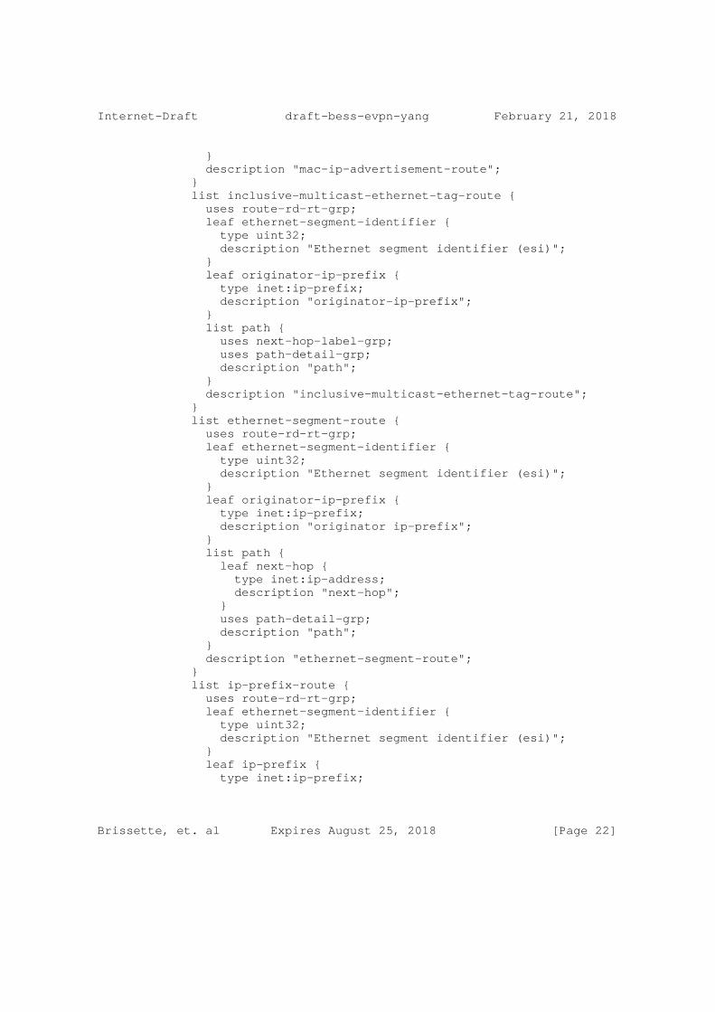
Internet-Draft draft-bess-evpn-yang February 21, 2018
} description "mac-ip-advertisement-route"; } list inclusive-multicast-ethernet-tag-route { uses route-rd-rt-grp; leaf ethernet-segment-identifier { type uint32; description "Ethernet segment identifier (esi)"; } leaf originator-ip-prefix { type inet:ip-prefix; description "originator-ip-prefix"; } list path { uses next-hop-label-grp; uses path-detail-grp; description "path"; } description "inclusive-multicast-ethernet-tag-route"; } list ethernet-segment-route { uses route-rd-rt-grp; leaf ethernet-segment-identifier { type uint32; description "Ethernet segment identifier (esi)"; } leaf originator-ip-prefix { type inet:ip-prefix; description "originator ip-prefix"; } list path { leaf next-hop { type inet:ip-address; description "next-hop"; } uses path-detail-grp; description "path"; } description "ethernet-segment-route"; } list ip-prefix-route { uses route-rd-rt-grp; leaf ethernet-segment-identifier { type uint32; description "Ethernet segment identifier (esi)"; } leaf ip-prefix { type inet:ip-prefix;
Brissette, et. al Expires August 25, 2018 [Page 22]

Internet-Draft draft-bess-evpn-yang February 21, 2018
description "ip-prefix"; } list path { uses next-hop-label-grp; uses path-detail-grp; description "path"; } description "ip-prefix route"; } } container statistics { config false; description "Statistics"; leaf tx-count { type uint32; description "transmission count"; } leaf rx-count { type uint32; description "receive count"; } container detail { description "Detailed statistics"; leaf broadcast-tx-count { type uint32; description "broadcast transmission count"; } leaf broadcast-rx-count { type uint32; description "broadcast receive count"; } leaf multicast-tx-count { type uint32; description "multicast transmission count"; } leaf multicast-rx-count { type uint32; description "multicast receive count"; } leaf unknown-unicast-tx-count { type uint32; description "unknown unicast transmission count"; } leaf unknown-unicast-rx-count { type uint32; description "unknown-unicast receive count"; } }
Brissette, et. al Expires August 25, 2018 [Page 23]

Internet-Draft draft-bess-evpn-yang February 21, 2018
} } } }
/* augments */
augment "/pw:pseudowires/pw:pseudowire/pw:pw-type" { description "Augment for an L2VPN instance to add EVPN VPWS " + "pseudowire"; case evpn-pw { container evpn-pw { description "EVPN pseudowire"; leaf remote-id { type uint32; description "Remote pseudowire ID"; } leaf local-id { type uint32; description "Local pseudowire ID"; } } } }
augment "/ni:network-instances/ni:network-instance/ni:ni-type" + "/l2vpn:l2vpn" { description "Augment for an L2VPN instance and EVPN association"; leaf evpn-instance { type evpn-instance-ref; description "Reference to an EVPN instance"; } }
augment "/ni:network-instances/ni:network-instance/ni:ni-type" + "/l2vpn:l2vpn" { when "l2vpn:type = ’l2vpn:vpls-instance-type’" { description "Constraints only for VPLS pseudowires"; } description "Augment for VPLS instance"; container vpls-contstraints { must "not(boolean(/pw:pseudowires/pw:pseudowire" + " [pw:name = current()/../l2vpn:endpoint" + " /l2vpn:pw/l2vpn:name]" + " /evpn-pw/remote-id)) and " + "not(boolean(/pw:pseudowires/pw:pseudowire" + " [pw:name = current()/../l2vpn:endpoint" + " /l2vpn:pw/l2vpn:name]" +
Brissette, et. al Expires August 25, 2018 [Page 24]

Internet-Draft draft-bess-evpn-yang February 21, 2018
" /evpn-pw/local-id)) and " + "not(boolean(/pw:pseudowires/pw:pseudowire" + " [pw:name = current()/../l2vpn:endpoint" + " /l2vpn:primary-pw/l2vpn:name]" + " /evpn-pw/remote-id)) and " + "not(boolean(/pw:pseudowires/pw:pseudowire" + " [pw:name = current()/../l2vpn:endpoint" + " /l2vpn:primary-pw/l2vpn:name]" + " /evpn-pw/local-id)) and " + "not(boolean(/pw:pseudowires/pw:pseudowire" + " [pw:name = current()/../l2vpn:endpoint" + " /l2vpn:backup-pw/l2vpn:name]" + " /evpn-pw/remote-id)) and " + "not(boolean(/pw:pseudowires/pw:pseudowire" + " [pw:name = current()/../l2vpn:endpoint" + " /l2vpn:backup-pw/l2vpn:name]" + " /evpn-pw/local-id))" { description "A VPLS pseudowire must not be EVPN PW"; } description "VPLS constraints"; } }
/* Notifications */
notification evpn-state-change-notification { description "EVPN state change notification"; leaf evpn-instance { type evpn-instance-ref; description "Related EVPN instance"; } leaf state { type identityref { base evpn-notification-state; } description "State change notification"; } } } <CODE ENDS>
5. Security Considerations
The configuration, state, action and notification data defined in this document are designed to be accessed via the NETCONF protocol [RFC6241]. The lowest NETCONF layer is the secure transport layer and the mandatory-to-implement secure transport is SSH [RFC6242]. The NETCONF access control model [RFC6536] provides means to restrict
Brissette, et. al Expires August 25, 2018 [Page 25]

Internet-Draft draft-bess-evpn-yang February 21, 2018
access for particular NETCONF users to a pre-configured subset of all available NETCONF protocol operations and content.
The security concerns listed above are, however, no different than faced by other routing protocols. Hence, this draft does not change any underlying security issues inherent in [I-D.ietf-netmod-routing- cfg]
6. IANA Considerations
None.
7. References
7.1. Normative Reference
[RFC2119] Bradner, S., "Key words for use in RFCs to Indicate Requirement Levels", BCP 14, RFC 2119, DOI 10.17487/RFC2119, March 1997, <http://www.rfc- editor.org/info/rfc2119>.
7.2. Informative References
[RFC6241] Enns, R., Ed., Bjorklund, M., Ed., Schoenwaelder, J., Ed., and A. Bierman, Ed., "Network Configuration Protocol (NETCONF)", RFC 6241, DOI 10.17487/RFC6241, June 2011, <http://www.rfc-editor.org/info/rfc6241>.
[RFC6020] Bjorklund, M., Ed., "YANG - A Data Modeling Language for the Network Configuration Protocol (NETCONF)", RFC 6020, DOI 10.17487/RFC6020, October 2010, <http://www.rfc- editor.org/info/rfc6020>.
[RFC6242] Wasserman, M., "Using the NETCONF Protocol over Secure Shell (SSH)", RFC 6242, DOI 10.17487/RFC6242, June 2011, <http://www.rfc-editor.org/info/rfc6242>.
[RFC6536] Bierman, A. and M. Bjorklund, "Network Configuration Protocol (NETCONF) Access Control Model", RFC 6536, DOI 10.17487/RFC6536, March 2012, <http://www.rfc- editor.org/info/rfc6536>.
[RFC7209] Sajassi, A., Aggarwal, R., Uttaro, J., Bitar, N., Henderickx, W., and A. Isaac, "Requirements for Ethernet VPN (EVPN)", RFC 7209, DOI 10.17487/RFC7209, May 2014, <http://www.rfc-editor.org/info/rfc7209>.
Brissette, et. al Expires August 25, 2018 [Page 26]
Internet-Draft draft-bess-evpn-yang February 21, 2018
[RFC7432] Sajassi, A., Ed., Aggarwal, R., Bitar, N., Isaac, A., Uttaro, J., Drake, J., and W. Henderickx, "BGP MPLS-Based Ethernet VPN", RFC 7432, DOI 10.17487/RFC7432, February 2015, <http://www.rfc-editor.org/info/rfc7432>.
[RFC7623] Sajassi, A., Ed., Salam, S., Bitar, N., Isaac, A., and W. Henderickx, "Provider Backbone Bridging Combined with Ethernet VPN (PBB-EVPN)", RFC 7623, DOI 10.17487/RFC7623, September 2015, <http://www.rfc-editor.org/info/rfc7623>.
Authors’ Addresses
Patrice Brissette Cisco Systems, Inc. EMail: [email protected]
Himanshu Shah Ciena Corporation EMail: [email protected]
Helen Chen Jabil EMail: [email protected]
Iftekar Hussain Infinera Corporation EMail: [email protected]
Kishore Tiruveedhula Juniper Networks EMail: [email protected]
Jorge Rabadan Nokia EMail: [email protected]
Ali Sajassi Cisco Systems, Inc. EMail: [email protected]
Zhenbin Li Huawei Technologies EMail: [email protected]
Brissette, et. al Expires August 25, 2018 [Page 27]

BESS WG A. DolganowInternet-Draft J. KotalwarUpdates: 6514 6625 7524 (if approved) NokiaIntended status: Standards Track E. Rosen, Ed.Expires: August 30, 2018 Z. Zhang Juniper Networks, Inc. February 26, 2018
Explicit Tracking with Wild Card Routes in Multicast VPN draft-ietf-bess-mvpn-expl-track-08
Abstract
The MVPN specifications provide procedures to allow a multicast ingress node to invoke "explicit tracking" for a multicast flow or set of flows, thus learning the egress nodes for that flow or set of flows. However, the specifications are not completely clear about how the explicit tracking procedures work in certain scenarios. This document provides the necessary clarifications. It also specifies a new, optimized explicit tracking procedure. This new procedure allows an ingress node, by sending a single message, to request explicit tracking of each of a set of flows, where the set of flows is specified using a wildcard mechanism. This document updates RFCs 6514, 6625, and 7524.
Status of This Memo
This Internet-Draft is submitted in full conformance with the provisions of BCP 78 and BCP 79.
Internet-Drafts are working documents of the Internet Engineering Task Force (IETF). Note that other groups may also distribute working documents as Internet-Drafts. The list of current Internet- Drafts is at https://datatracker.ietf.org/drafts/current/.
Internet-Drafts are draft documents valid for a maximum of six months and may be updated, replaced, or obsoleted by other documents at any time. It is inappropriate to use Internet-Drafts as reference material or to cite them other than as "work in progress."
This Internet-Draft will expire on August 30, 2018.
Copyright Notice
Copyright (c) 2018 IETF Trust and the persons identified as the document authors. All rights reserved.
Dolganow, et al. Expires August 30, 2018 [Page 1]

Internet-Draft MVPN: Explicit Tracking and WildCards February 2018
This document is subject to BCP 78 and the IETF Trust’s Legal Provisions Relating to IETF Documents (https://trustee.ietf.org/license-info) in effect on the date of publication of this document. Please review these documents carefully, as they describe your rights and restrictions with respect to this document. Code Components extracted from this document must include Simplified BSD License text as described in Section 4.e of the Trust Legal Provisions and are provided without warranty as described in the Simplified BSD License.
Table of Contents
1. Introduction . . . . . . . . . . . . . . . . . . . . . . . . 2 2. The Explicit Tracking Flags . . . . . . . . . . . . . . . . . 5 3. Match for Tracking vs. Match for Reception . . . . . . . . . 6 4. Ingress Node Initiation of Tracking . . . . . . . . . . . . . 8 5. Egress Node Response to the Match for Tracking . . . . . . . 10 5.1. General Egress Node Procedures . . . . . . . . . . . . . 10 5.2. Responding to the LIR-pF Flag . . . . . . . . . . . . . . 11 5.3. When the Egress Node is an ABR or ASBR . . . . . . . . . 14 6. Ingress Node Handling of Received Leaf A-D Routes with LIR-pF Set . . . . . . . . . . . . . . . . . . . . . . . . . 15 7. Acknowledgments . . . . . . . . . . . . . . . . . . . . . . . 16 8. IANA Considerations . . . . . . . . . . . . . . . . . . . . . 16 9. Security Considerations . . . . . . . . . . . . . . . . . . . 16 10. References . . . . . . . . . . . . . . . . . . . . . . . . . 16 10.1. Normative References . . . . . . . . . . . . . . . . . . 16 10.2. Informative References . . . . . . . . . . . . . . . . . 17 Authors’ Addresses . . . . . . . . . . . . . . . . . . . . . . . 17
1. Introduction
[RFC6513] and [RFC6514] define the "Selective Provider Multicast Service Interface Auto-Discovery route" (S-PMSI A-D route).
Per those RFCs, the S-PMSI A-D route contains a Network Layer Reachability Information (NLRI) field that identifies a particular multicast flow. In the terminology of those RFCs, each flow is denoted by (C-S,C-G), where C-S is an IP source address and C-G is an IP multicast address, both in the address space of a VPN customer. The (C-S,C-G) of the multicast flow is encoded into the NLRI field.
An S-PMSI A-D route also carries a PMSI Tunnel attribute (PTA). Typically, the PTA is used to identify a tunnel through the provider backbone network (a "P-tunnel").
By originating an S-PMSI A-D route identifying a particular multicast flow and a particular P-tunnel, a node is advertising the following:
Dolganow, et al. Expires August 30, 2018 [Page 2]

Internet-Draft MVPN: Explicit Tracking and WildCards February 2018
if the node has to transmit packets of the identified flow over the backbone, it will transmit them through the identified tunnel.
[RFC6513] and [RFC6514] also define a procedure that allows an ingress node of particular multicast flow to determine the set of egress nodes that have requested to receive that flow from that ingress node. The ability of an ingress node to identify the egress nodes for a particular flow is known as "explicit tracking". An ingress node requests explicit tracking by setting a flag (the "Leaf Information Required" flag, or LIR) in the PTA. When an egress node receives an S-PMSI A-D route with LIR set, the egress node originates a Leaf A-D route whose NLRI field contains the NLRI from the corresponding S-PMSI A-D route. In this way, the egress node advertises that it has requested to receive the particular flow identified in the NLRI of that S-PMSI A-D route.
[RFC6513] and [RFC6514] also allow an ingress node to originate an S-PMSI A-D route whose PTA has LIR set, but which does not identify any P-tunnel. This mechanism can be used when it is desired to do explicit tracking of a flow without at the same time binding that flow to a particular P-tunnel.
[RFC6625] (and other RFCs that update it) extends the specification of S-PMSI A-D routes, and allows an S-PMSI A-D route to encode a wildcard in its NLRI. Either the C-S or the C-G or both can be replaced by wildcards. These routes are known as (C-*,C-S) S-PMSI A-D routes, or as (C-S,C-*) S-PMSI A-D routes, or as (C-*,C-*) S-PMSI A-D routes, depending on whether the C-S or C-G or both have been replaced by wildcards. These routes are known jointly as "wildcard S-PMSI A-D routes".
One purpose of this document is to clarify the way that the explicit tracking procedures of [RFC6513] and [RFC6514] are applied when wildcard S-PMSI A-D routes are used.
In addition, this document addresses the following scenario, which is not addressed in [RFC6513], [RFC6514], or [RFC6625]. Suppose an ingress node originates an S-PMSI A-D route whose NLRI specifies, for example, (C-*,C-*) (i.e., both C-S and C-G are replaced by wildcards), and whose PTA identifies a particular P-tunnel. Now suppose that the ingress node wants explicit tracking for each individual flow that it transmits (following the procedures of [RFC6625]) on that P-tunnel.
In this example, if the ingress node sets LIR in the PTA of the wildcard S-PMSI A-D route, each egress node that needs to receive a flow from the ingress node will respond with a Leaf A-D route whose NLRI specifies contains the (C-*,C-*) wildcard. This allows the
Dolganow, et al. Expires August 30, 2018 [Page 3]

Internet-Draft MVPN: Explicit Tracking and WildCards February 2018
ingress node to determine the set of egress nodes that are interested in receiving flows from the ingress node. However, it does not allow the ingress node to determine exactly which flows are of interest to which egress nodes.
If the ingress node needs to determine which egress nodes are interested in receiving which flows, it needs to originate an S-PMSI A-D route for each individual (C-S,C-G) flow that it is transmitting, and it needs to set LIR in the PTA of each such route. However, since all the flows are being sent through the tunnel identified in the (C-*,C-*) S-PMSI A-D route, there is no need to identify a tunnel in the PTA of each (C-S,C-G) S-PMSI A-D route. Per [RFC6514], the PTA of the (C-S,C-G) S-PMSI A-D routes can specify "no tunnel information". This procedure allows explicit tracking of individual flows, even though all those flows are assigned to tunnels in wildcard S-PMSI A-D routes.
However, this procedure requires several clarifications:
o The procedures of [RFC6625] do not address the case of an S-PMSI A-D route whose NLRI contains wild cards, but whose PTA specifies "no tunnel info".
o If it is desired to send a set of flows through the same tunnel (where that tunnel is advertised in a wildcard S-PMSI A-D route), but it is also desired to explicitly track each individual flow transmitted over that tunnel, one has to send an S-PMSI A-D route (with LIR set in the PTA) for each individual flow. It would be more optimal if the ingress node could just send a single wildcard S-PMSI A-D route binding the set of flows to a particular tunnel, and have the egress nodes respond with Leaf A-D routes for each individual flow.
o [RFC6513] and [RFC6514] support the notion of "segmented P-tunnels", where "segmentation" occurs at Autonomous System Border Routers (ASBRs); [RFC7524] extends the notion of segmented P-tunnels so that segmentation can occur at Area Border Routers (ABRs). One can think of a segmented P-tunnel as passing through a number of "segmentation domains". In each segmentation domain, a given P-tunnel has an ingress node and a set of egress nodes. The explicit tracking procedures allow an ingress node of a particular segmentation domain to determine, for a particular flow or set of flows, the egress nodes of that segmentation domain. This has given rise to two further problems:
* The explicit tracking procedures do not allow an ingress node to "see" past the boundaries of the segmentation domain.
Dolganow, et al. Expires August 30, 2018 [Page 4]

Internet-Draft MVPN: Explicit Tracking and WildCards February 2018
* The prior specifications do not make it very clear whether a segmented tunnel egress node, upon receiving an S-PMSI A-D route whose PTA specifies "no tunnel information", is expected to forward the S-PMSI A-D route, with the same PTA, to the next segmentation domain.
These problems are addressed in Section 5.3.
The key words "MUST", "MUST NOT", "REQUIRED", "SHALL", "SHALL NOT", "SHOULD", "SHOULD NOT", "RECOMMENDED", "NOT RECOMMENDED", "MAY", and "OPTIONAL" in this document are to be interpreted as described in BCP 14 [RFC2119] [RFC8174] when, and only when, they appear in all capitals, as shown here.
2. The Explicit Tracking Flags
[RFC6514] defines one flag in the PTA, the "Leaf Info Required" (LIR) flag, that is used for explicit tracking.
This document defines a new flag in the flags field of the PMSI Tunnel attribute. This new flag is known as the "Leaf Info Required per Flow" bit (LIR-pF). This flag may be set in the PTA of a (C-*,C-*), (C-*,C-G), or (C-S,C-*) S-PMSI A-D route. The conditions under which it should be set by the originator of the route are discussed in Section 4. The significance of the flag in a received S-PMSI A-D route is discussed in Sections 5 and 5.2.
If the LIR-pF flag is set in the PTA of an S-PMSI A-D route, the LIR flag of that PTA MUST also be set.
Note that support for the LIR-pF flag is OPTIONAL. This flag SHOULD NOT be set unless it is known that all the PEs that are to receive the route carrying the PTA support the flag. How this is known is outside the scope of this document.
The LIR-pF flag may also be set in the PTA of a Leaf A-D route. The conditions under which it should be set by the originator of the route are discussed in Section 5.2. The significance of the flag in a received Leaf A-D route is discussed in Section 6.
Use of this flag in the PTA carried by other route types is outside the scope of this document. Use of this flag in the PTA carried by an S-PMSI A-D routes whose NLRI does not contain a wildcard is outside the scope of this document.
It is worth noting what will happen if the LIR-pF flag is set in the PTA of, for example, a (C-*,C-*) S-PMSI A-D route originated by an
Dolganow, et al. Expires August 30, 2018 [Page 5]

Internet-Draft MVPN: Explicit Tracking and WildCards February 2018
ingress node, but one or more of the egress nodes do not support the LIR-pF flag:
1. The ingress node will not be able to determine the complete set of egress node that are expecting a particular multicast flow from that ingress node.
2. Depending upon the tunnel type, the ingress node may send a particular multicast flow only to the egress nodes that do support the LIR-pF flag. From the perspective of egress nodes that do not support LIR-pF, certain flows may appear to be "blackholed".
It is also worth noting that it is possible for an ingress node that sets the LIR-pF flag in an S-PMSI A-D route to detect the presence of egress nodes that do not support this flag.
Since an ingress node that sets the LIR-pF flag is also REQUIRED to set the LIR flag, egress nodes that do not support the LIR-pF flag will respond, as specified in [RFC6514], to the ingress node’s (C-*,C-*) S-PMSI A-D route with a Leaf A-D route operator.
As will be discussed in Section 5.2, any Leaf A-D route originated in response to an S-PMSI A-D route that has LIR-pF set will carry a PTA whose LIR-pF flag is set. If an ingress node receives a Leaf A-D route whose "route key" field corresponds to the NLRI of an S-PMSI A-D route whose PTA has LIR-pF set, but the Leaf A-D route lacks a PTA or has a PTA where LIR-pF is clear, the ingress node can conclude that the egress node originating that Leaf A-D route does not support the LIR-pF flag.
The software at the ingress node SHOULD detect this, and should have a way of alerting the operator that the deployment is not properly configured.
3. Match for Tracking vs. Match for Reception
Section 3.2 of [RFC6625] specifies a set of rules for finding the S-PMSI A-D route that is the "match for data reception" (or more simply, the "match for reception") of a given (C-S,C-G) or (C-*,C-G) state. These rules do not take into account the fact that some S-PMSI A-D routes may not be carrying PTAs at all, or may be carrying PTAs that do not identify any P-tunnel. (A PTA that does not identify any P-tunnel is one whose "tunnel type" field has been set to "no tunnel information", as specified in Section 5 of [RFC6514].)
The rules for finding a "match for reception" in [RFC6625] are hereby modified as follows:
Dolganow, et al. Expires August 30, 2018 [Page 6]

Internet-Draft MVPN: Explicit Tracking and WildCards February 2018
When applying the rules of Section 3.2.1 or 3.2.2 of [RFC6625], it is REQUIRED to ignore any S-PMSI A-D route that has no PTA, or whose PTA specifies "no tunnel information".
There are other RFCs that update [RFC6625] and that modify the rules for finding a "match for reception". See, e.g., [RFC7582] and [RFC7900]. When applying those modified rules, it is REQUIRED to ignore any S-PMSI A-D route that has no PTA, or whose PTA specifies "no tunnel information".
We also introduce a new notion, the "match for tracking":
For a given C-flow ((C-S,C-G) or (C-*,C-G)) the "match for tracking" is chosen as follows. Ignore any S-PMSI A-D route that has no PTA. Also ignore any S-PMSI A-D route whose PTA specifies "no tunnel information", but does not have either LIR or LIR-pF set. (That is, DO NOT ignore an S-PMSI A-D route that has a PTA specifying "no tunnel information" unless its LIR and LIR-pF bits are both clear). Then apply the rules (from [RFC6625] and other documents that that update it) for finding the "match for reception". The result (if any) is the match for tracking".
Note that the procedure for finding the match for tracking takes into account S-PMSI A-D routes whose PTAs specify "no tunnel information" and that have either LIR or LIR-pf set. The procedure for finding the match for reception ignores such routes.
We will clarify this with a few examples. In these examples, we assume that there is only one segmentation domain. In this case, the ingress and egress nodes are Provider Edge (PE) routers.
Suppose a given PE router, PE1, has chosen PE2 as the "upstream PE" ([RFC6513]) for a given flow (C-S1,C-G1). And suppose PE1 has installed the following two routes that were originated by PE2:
o Route1: A (C-*,C-*) S-PMSI A-D route, whose PTA specifies a tunnel.
o Route2: A (C-S1,C-G1) S-PMSI A-D route, whose PTA specifies "no tunnel info" and has LIR set.
Route1 is (C-S1,C-G1)’s match for reception, and Route2 is (C-S1,C-G1)’s match for tracking.
Continuing this example, suppose:
o PE1 has chosen PE2 as the upstream PE for a different flow, (C-S2,C-G2).
Dolganow, et al. Expires August 30, 2018 [Page 7]

Internet-Draft MVPN: Explicit Tracking and WildCards February 2018
o PE2 has not originated an S-PMSI A-D route for (C-S2,C-G2).
In this case, PE1 would consider Route1 to be (C-S2,C-G2)’s match for tracking as well as its match for reception.
Also note that if a match for tracking does not have the LIR flag or the LIR-pF flag set, no explicit tracking information will be generated. See Section 5.
As another example, suppose PE1 has installed the following two routes that were originated by PE2:
o Route1: A (C-*,C-*) S-PMSI A-D route (irrespective of whether the PTA specifies a tunnel)
o Route2: A (C-S1,C-G1) S-PMSI A-D route whose PTA specifies a tunnel.
Then Route2 is both the "match for reception" and the "match for tracking" for (C-S1,C-G1).
Note that for a particular C-flow, PE1’s match for reception might be the same route as its match for tracking, or its match for reception might be a "less specific" route than its match for tracking. But its match for reception can never be a "more specific" route than its match for tracking.
4. Ingress Node Initiation of Tracking
An ingress node that needs to initiate explicit tracking for a particular flow or set of flows can do so by performing one of the following procedures:
1. An ingress node can initiate explicit tracking for (C-S1,C-G1) by originating an S-PMSI A-D route that identifies (C-S1,C-G1) in its NLRI, including a PTA in that route, and setting the LIR flag in that PTA. The PTA may specify a particular tunnel, or may specify "no tunnel info".
However, the PTA of the (C-S1,C-G1) S-PMSI A-D route SHOULD NOT specify "no tunnel info" unless the ingress node also originates an A-D route carrying a PTA that specifies the tunnel to be used for carrying (C-S1,C-G1) traffic. Such a route could be an I-PMSI A-D route, a (C-*,C-G1) S-PMSI A-D route, a (C-S1,C-*) S-PMSI A-D route, or a (C-*,C-*) S-PMSI A-D route. (There is no point in requesting explicit tracking for a given flow if there is no tunnel on which the flow is being carried.)
Dolganow, et al. Expires August 30, 2018 [Page 8]

Internet-Draft MVPN: Explicit Tracking and WildCards February 2018
Note that if the ingress node originates a wildcard S-PMSI A-D route carrying a PTA specifying the tunnel to be used for carrying (C-S1,C-G1) traffic, and if that PTA has the LIR-pF bit set, then explicit tracking for (C-S1,C-G1) is requested by that S-PMSI A-D route. In that case, the ingress node SHOULD NOT originate a (C-S1,C-G1) S-PMSI A-D route whose PTA specifies "no tunnel info"; such a route would not provide any additional functionality.
To terminate explicit tracking that has been initiated by an S-PMSI A-D route whose PTA specifies "no tunnel info", the ingress node withdraws the route.
To terminate explicit tracking that has been initiated by an S-PMSI A-D route whose PTA specifies a tunnel, the ingress node re-originates the route without the LIR flag set.
2. The following procedure can be used if and only if it is known that the egress nodes support the optional LIR-pF flag. If the ingress node originates a wildcard S-PMSI A-D route, it can initiate explicit tracking for the individual flows that match the wildcard route by setting the LIR-pF flag in the PTA of the wildcard route. If an egress node needs to receive one or more flows for which that wildcard route is a match for tracking, the egress node will originate a Leaf A-D route for each such flow, as specified in Section 5.2).
When following this procedure, the PTA of the S-PMSI A-D route may specify a tunnel, or may specify "no tunnel info". The choice between these two options is determined by considerations that are outside the scope of this document.
To terminate explicit tracking that has been initiated by an S-PMSI A-D route whose PTA specifies "no tunnel info", the ingress node withdraws the route.
To terminate explicit tracking that has been initiated by an S-PMSI A-D route whose PTA specifies a tunnel, the ingress node re-originates the route without either the LIR or LIR-pF flags set.
Note that this procedure (procedure 2 of Section 4) may not yield the expected results if there are egress nodes that do not support the LIR-pF flag, and hence SHOULD NOT be used in that case.
Dolganow, et al. Expires August 30, 2018 [Page 9]

Internet-Draft MVPN: Explicit Tracking and WildCards February 2018
5. Egress Node Response to the Match for Tracking
5.1. General Egress Node Procedures
There are four cases to consider:
1. With regard to a particular (C-S,C-G) or (C-*,C-G) multicast state, the egress node’s match for tracking is same as its match for reception, and neither LIR nor LIR-pF flags are on.
In this case, the egress node does not originate a Leaf A-D route in response to the match for reception/tracking, and there is no explicit tracking of the flow. This document specifies no new procedures for this case.
2. With regard to a particular (C-S,C-G) or (C-*,C-G) multicast state, the egress node’s match for tracking is the same as its match for reception, LIR is set, but LIR-pF is not set.
In this case, a Leaf A-D route is originated by the egress node, corresponding to the S-PMSI A-D route that is the match for reception/tracking. Construction of the Leaf A-D route is as specified in [RFC6514]; this document specifies no new procedures for this case.
3. With regard to a particular (C-S,C-G) or (C-*,C-G) multicast state, the egress node’s match for tracking is the same as its match for reception, and LIR-pF is set. The egress node MUST follow whatever procedures are required by other specifications, based on the match for reception. If the egress node supports the LIR-pF flag, it MUST also follow the procedures of Section 5.2.
4. With regard to a particular (C-S,C-G) or (C-*,C-G) multicast state, the egress node’s match for tracking is not the same as its match for reception. This can only happen if the match for tracking has a PTA specifying "no tunnel info", with either LIR or LIR-pF set. In this case, the egress node must respond, separately, BOTH to the match for tracking and to the match for reception.
When responding to the match for reception, the egress node MUST ignore the LIR-pF flag. However, the LIR flag is processed normally per the procedures for the match for reception.
If the match for tracking has LIR set and if either (a) the egress node does not support LIR-pF, or (b) LIR-pF is not set,
Dolganow, et al. Expires August 30, 2018 [Page 10]

Internet-Draft MVPN: Explicit Tracking and WildCards February 2018
then the behavior of the egress node is not affected by the procedures of this document.
If the match for tracking has LIR-pF set, and the egress node supports the LIR-pF flag, the egress node must originate one or more Leaf A-D routes, as specified in Section 5.2.
Note that if LIR is set in the PTA of the match for reception, the egress node may need to originate one or more Leaf A-D routes corresponding to the match for tracking, as well as originating a Leaf A-D route corresponding to the match for reception.
5.2. Responding to the LIR-pF Flag
To respond to a match for tracking that has LIR-pF set, an egress node originates one or more Leaf A-D routes.
Suppose the egress node has multicast state for a (C-S,C-G) or a (C-*,C-G) flow, and has determined a particular S-PMSI A-D route, which has the LIR-pF flag set, to be the match for tracking for that flow. Then if the egress node supports the LIR-pF flag, it MUST originate a Leaf A-D route whose NLRI identifies that particular flow. Note that if a single S-PMSI A-D route (with wild cards) is the match for tracking for multiple flows, the egress node may need to originate multiple Leaf A-D routes, one for each such flow. We say that, from the perspective of a given egress node, a given S-PMSI A-D route tracks the set of flows for which it is the match for tracking. Each of the Leaf A-D routes originated in response to that S-PMSI A-D route tracks a single such flow.
The NLRI of each the Leaf A-D route that tracks a particular flow is constructed as follows. The "route key" field of the NLRI will have the following format:
Dolganow, et al. Expires August 30, 2018 [Page 11]

Internet-Draft MVPN: Explicit Tracking and WildCards February 2018
+-----------------------------------+ | RD (8 octets) | +-----------------------------------+ | Multicast Source Length (1 octet) | +-----------------------------------+ | Multicast Source (Variable) | +-----------------------------------+ | Multicast Group Length (1 octet) | +-----------------------------------+ | Multicast Group (Variable) | +-----------------------------------+ | Ingress PE’s IP address | +-----------------------------------+
Figure 1: NLRI of S-PMSI A-D Route
o The "ingress PE" address is taken from the "originating router" field of the NLRI of the S-PMSI A-D route that is the match for tracking.
o The multicast source and group fields specify the S and G of one of the flow being tracked by this Leaf A-D route. If a (C-*,C-G) is being tracked by this Leaf A-D route, the source field is omitted, and its length is set to 0.
o The Route Distinguisher (RD) field is set to the value of the RD field from the NLRI of the S-PMSI A-D route.
The encoding of these Leaf A-D routes is similar to the encoding of the Leaf A-D routes described in section 6.2.2 of [RFC7524], which were designed for the support of "global table multicast". However, that document sets the RD to either 0 or -1; following the procedures of this document, the RD will never be 0 or -1. Therefore Leaf A-D routes constructed according to the procedures of this section can always be distinguished from the Leaf A-D routes constructed according to the procedures of section 6.2.2 of [RFC7524]. Also, Leaf A-D routes constructed according to the procedures of this section are VPN-specific routes, and will always carry an IP-address- specific Route Target, as specified in [RFC6514].
If a Leaf A-D route is originated as a response to a match for tracking whose PTA specifies "no tunnel info", the Leaf A-D route MUST carry a PTA that specifies "no tunnel info". The LIR-pF flag in this PTA MUST be set.
In the case where the match for tracking and the match for reception are the same, the PTA of the match may have both the LIR and the
Dolganow, et al. Expires August 30, 2018 [Page 12]

Internet-Draft MVPN: Explicit Tracking and WildCards February 2018
LIR-pF flags set. This may cause the egress node to originate one Leaf A-D route in response to the LIR bit, and one or more Leaf A-D routes in response to the LIR-pF bit. Each such Leaf A-D route MUST have a PTA, and the LIR-pF flag of that PTA MUST be set. Note that when the match for tracking is the same as the match for reception, the PTA of the match for tracking/reception will have specified a tunnel type. The following rules specify how the PTA of the Leaf A-D route is to be constructed:
o If the tunnel type of the PTA attached to the match for tracking/ reception is Ingress Replication, the Leaf A-D route’s PTA MAY specify Ingress Replication. In this case, the MPLS Label field of the PTA MAY be a non-zero value. If so, this label value will be used by the ingress PE when it transmits, to the egress PE, packets of the flow identified in the Leaf A-D route’s NLRI.
Alternatively, the egress PE MAY specify an MPLS label value of zero, or it MAY specify a tunnel type of "no tunnel info". In either of these cases, when the ingress PE transmits packets of the identified flow to the egress PE, it will use the label that the egress PE specified in the PTA of the Leaf A-D route that it originated in response to the LIR bit of the match for reception.
o If the tunnel type of the PTA attached to the match for tracking/ reception is any of the other tunnel types listed in [RFC6514] Section 5, the PTA attached to the Leaf A-D route MUST specify a tunnel type of "no tunnel info".
o When additional tunnel types are defined, the specification for how MVPN is to use those tunnel types must also specify how to construct the PTA of a Leaf A-D route that is originated in response to the LIR-pF flag. As an example, see [BIER-MVPN].
Of course, an egress node that originates such Leaf A-D routes needs to remember which S-PMSI A-D route caused these Leaf A-D routes to be originated; if that S-PMSI A-D route is withdrawn, those Leaf A-D routes MUST be withdrawn.
Similarly, a Leaf A-D route needs to be withdrawn (either implicitly or explicitly) if the egress node changes its Upstream Multicast Hop (UMH) ([RFC6513]) for the flow that is identified in the Leaf A-D route’s NLRI, or if the egress node that originated the route no longer needs to receive the flow identified in the NLRI of the route.
Note that an egress node may acquire (C-S,C-G) state or (C-*,C-G) state after it has already received the S-PMSI A-D that is the match for tracking for that state. In this case, a Leaf A-D route needs to
Dolganow, et al. Expires August 30, 2018 [Page 13]

Internet-Draft MVPN: Explicit Tracking and WildCards February 2018
be originated at that time, and the egress node must remember that the new Leaf A-D route corresponds to that match for tracking.
Note that if a particular S-PMSI A-D route is a match for tracking but not a match for reception, the LIR bit in its PTA is ignored if the LIR-pF bit is set.
5.3. When the Egress Node is an ABR or ASBR
When segmented P-tunnels are used, the ingress and egress nodes may be ABRs or ASBRs. An egress ABR/ASBR that receives and installs an S-PMSI A-D route also forwards that route. If the PTA of an installed S-PMSI A-D route specifies a tunnel, the egress ABR/ASBR MAY change the PTA to specify a different tunnel type (as discussed in [RFC6514] and/or [RFC7524]). The egress ABR/ASBR may also need to originate a Leaf A-D route, as specified in [RFC6514] and/or [RFC7524].
Suppose the forwarded S-PMSI A-D route has a PTA specifying a tunnel, and also has LIR-pF set. The egress ABR/ASBR originates a corresponding Leaf A-D route for a given (C-S,C-G) only if it knows that it needs to receive that flow. It will know this by virtue of receiving a corresponding Leaf A-D route from downstream. (In the case where the PTA specifies a tunnel but LIR-pF is not set, this document does not specify any new procedures.)
The procedures in the remainder of this section apply only when an egress ABR/ASBR has installed an S-PMSI A-D route whose PTA specifies "no tunnel info" but has LIR or LIR-pF set.
If the PTA of the installed S-PMSI A-D route specifies "no tunnel info", the egress ABR/ASBR MUST pass the PTA along unchanged when it forwards the S-PMSI A-D route. (That is, a PTA specifying "no tunnel info" MUST NOT be changed into a PTA specifying a tunnel.) Furthermore, if the PTA specifies "no tunnel info", the LIR and LIR-pF flags in the PTA MUST be passed along unchanged.
As a result of propagating such an S-PMSI A-D route, the egress ABR/ ASBR may receive one or more Leaf A-D routes that correspond to that S-PMSI A-D route. These routes will be received carrying an IP- address-specific Route Target (RT) Extended Community that specifies the address of the egress ABR/ASBR. The egress ABR/ASBR will propagate these Leaf A-D routes, after changing the RT as follows. The "global administrator" field of the modified RT will be set to the IP address taken either from the S-PMSI A-D route’s next hop field ([RFC6514]), or from its Segmented P2MP Next Hop Extended Community ([RFC7524]).
Dolganow, et al. Expires August 30, 2018 [Page 14]

Internet-Draft MVPN: Explicit Tracking and WildCards February 2018
This procedure enables the ingress PE to explicitly track the egress PEs for a given flow, even if segmented tunnels are being used. However, cross-domain explicit tracking utilizes S-PMSI A-D routes that do not specify tunnel information; therefore it can only be done when the S-PMSI A-D route which is a flow’s match for tracking is different than the S-PMSI A-D route which is that flow’s match for reception.
6. Ingress Node Handling of Received Leaf A-D Routes with LIR-pF Set
Consider the following situation:
o An ingress node, call it N, receives a Leaf A-D route, call it L.
o L carries an IP-address-specific RT identifying N.
o The route key field of L’s NLRI is not identical to the NLRI of any current I-PMSI or S-PMSI A-D route originated by N.
Per the procedures of [RFC6514] and [RFC7524], such a Leaf A-D route does not cause any MVPN-specific action to be taken by N.
This document modifies those procedures in the case where there is a current S-PMSI A-D route with a wildcard NLRI, originated by N, to which L is a valid response according to the procedures of Section 5.2. In this case, L MUST be processed by N.
Suppose that L’s PTA specifies a tunnel type of Ingress Replication, and that it also specifies a non-zero MPLS label. Then if N needs to send to L a packet belonging to the multicast flow or flows identified in L’s NLRI, N MUST use the specified label.
If L’s PTA meets any of the following conditions:
o It specifies a tunnel type of "no tunnel information", or
o It specifies a tunnel type of Ingress Replication, but specifies an MPLS label of zero, or
o It specifies another of the tunnel types listed in Section 5 of [RFC6514],
then the action taken by N when it receives L is a local matter. In this case, the Leaf A-D route L provides N with explicit tracking information for the flow identified by L’s NLRI. However, that information is for management/monitoring purposes and does not have an effect on the flow of multicast traffic.
Dolganow, et al. Expires August 30, 2018 [Page 15]

Internet-Draft MVPN: Explicit Tracking and WildCards February 2018
If L’s PTA specifies a tunnel type not mentioned above, the specification for how MVPN uses that tunnel type must specify the actions that N is to take upon receiving L. As an example, see [BIER-MVPN].
7. Acknowledgments
The authors wish to thank Robert Kebler for his ideas and comments. We also thank Stephane Litkowski for his thorough review and useful suggestions.
8. IANA Considerations
The LIR-pF flag needs to be added to the "P-Multicast Service Interface Tunnel (PMSI Tunnel) Attribute Flags" in the "Border Gateway Protocol (BGP) Parameters" registry. This registry is defined in [RFC7902]. The requested value is Bit Position 2. This document should be the reference.
9. Security Considerations
The Security Considerations of [RFC6513] and [RFC6514] apply.
By setting the LIR-pF flag in a single wildcard S-PMSI A-D route, a large number of Leaf A-D routes can be elicited. If this flag is set when not desired (through either error or malfeasance), a significant increase in control plane overhead can result. The specification of counter-measures for this problem is outside the scope of this document.
10. References
10.1. Normative References
[RFC2119] Bradner, S., "Key words for use in RFCs to Indicate Requirement Levels", BCP 14, RFC 2119, DOI 10.17487/RFC2119, March 1997, <https://www.rfc-editor.org/info/rfc2119>.
[RFC6513] Rosen, E., Ed. and R. Aggarwal, Ed., "Multicast in MPLS/ BGP IP VPNs", RFC 6513, DOI 10.17487/RFC6513, February 2012, <https://www.rfc-editor.org/info/rfc6513>.
[RFC6514] Aggarwal, R., Rosen, E., Morin, T., and Y. Rekhter, "BGP Encodings and Procedures for Multicast in MPLS/BGP IP VPNs", RFC 6514, DOI 10.17487/RFC6514, February 2012, <https://www.rfc-editor.org/info/rfc6514>.
Dolganow, et al. Expires August 30, 2018 [Page 16]

Internet-Draft MVPN: Explicit Tracking and WildCards February 2018
[RFC6625] Rosen, E., Ed., Rekhter, Y., Ed., Hendrickx, W., and R. Qiu, "Wildcards in Multicast VPN Auto-Discovery Routes", RFC 6625, DOI 10.17487/RFC6625, May 2012, <https://www.rfc-editor.org/info/rfc6625>.
[RFC7524] Rekhter, Y., Rosen, E., Aggarwal, R., Morin, T., Grosclaude, I., Leymann, N., and S. Saad, "Inter-Area Point-to-Multipoint (P2MP) Segmented Label Switched Paths (LSPs)", RFC 7524, DOI 10.17487/RFC7524, May 2015, <https://www.rfc-editor.org/info/rfc7524>.
[RFC7902] Rosen, E. and T. Morin, "Registry and Extensions for P-Multicast Service Interface Tunnel Attribute Flags", RFC 7902, DOI 10.17487/RFC7902, June 2016, <https://www.rfc-editor.org/info/rfc7902>.
[RFC8174] Leiba, B., "Ambiguity of Uppercase vs Lowercase in RFC 2119 Key Words", BCP 14, RFC 8174, DOI 10.17487/RFC8174, May 2017, <https://www.rfc-editor.org/info/rfc8174>.
10.2. Informative References
[BIER-MVPN] Rosen, E., Sivakumar, M., Aldrin, S., Dolganow, A., and T. Przygienda, "Multicast VPN Using BIER", internet-draft draft-ietf-bier-mvpn-10, February 2018.
[RFC7582] Rosen, E., Wijnands, IJ., Cai, Y., and A. Boers, "Multicast Virtual Private Network (MVPN): Using Bidirectional P-Tunnels", RFC 7582, DOI 10.17487/RFC7582, July 2015, <https://www.rfc-editor.org/info/rfc7582>.
[RFC7900] Rekhter, Y., Ed., Rosen, E., Ed., Aggarwal, R., Cai, Y., and T. Morin, "Extranet Multicast in BGP/IP MPLS VPNs", RFC 7900, DOI 10.17487/RFC7900, June 2016, <https://www.rfc-editor.org/info/rfc7900>.
Authors’ Addresses
Andrew Dolganow Nokia 438B Alexandra Rd #08-07/10 Alexandra Technopark Singapore 119968 Singapore
Email: [email protected]
Dolganow, et al. Expires August 30, 2018 [Page 17]

Internet-Draft MVPN: Explicit Tracking and WildCards February 2018
Jayant Kotalwar Nokia 701 East Middlefield Rd Mountain View, California 94043 United States of America
Email: [email protected]
Eric C. Rosen (editor) Juniper Networks, Inc. 10 Technology Park Drive Westford, Massachusetts 01886 United States of America
Email: [email protected]
Zhaohui Zhang Juniper Networks, Inc. 10 Technology Park Drive Westford, Massachusetts 01886 United States of America
Email: [email protected]
Dolganow, et al. Expires August 30, 2018 [Page 18]

BESS WG A. DolganowInternet-Draft J. KotalwarUpdates: 6514 6625 7524 (if approved) NokiaIntended status: Standards Track E. Rosen, Ed.Expires: October 21, 2018 Z. Zhang Juniper Networks, Inc. April 19, 2018
Explicit Tracking with Wild Card Routes in Multicast VPN draft-ietf-bess-mvpn-expl-track-09
Abstract
The MVPN specifications provide procedures to allow a multicast ingress node to invoke "explicit tracking" for a multicast flow or set of flows, thus learning the egress nodes for that flow or set of flows. However, the specifications are not completely clear about how the explicit tracking procedures work in certain scenarios. This document provides the necessary clarifications. It also specifies a new, optimized explicit tracking procedure. This new procedure allows an ingress node, by sending a single message, to request explicit tracking of each of a set of flows, where the set of flows is specified using a wildcard mechanism. This document updates RFCs 6514, 6625, and 7524.
Status of This Memo
This Internet-Draft is submitted in full conformance with the provisions of BCP 78 and BCP 79.
Internet-Drafts are working documents of the Internet Engineering Task Force (IETF). Note that other groups may also distribute working documents as Internet-Drafts. The list of current Internet- Drafts is at https://datatracker.ietf.org/drafts/current/.
Internet-Drafts are draft documents valid for a maximum of six months and may be updated, replaced, or obsoleted by other documents at any time. It is inappropriate to use Internet-Drafts as reference material or to cite them other than as "work in progress."
This Internet-Draft will expire on October 21, 2018.
Copyright Notice
Copyright (c) 2018 IETF Trust and the persons identified as the document authors. All rights reserved.
Dolganow, et al. Expires October 21, 2018 [Page 1]

Internet-Draft MVPN: Explicit Tracking and WildCards April 2018
This document is subject to BCP 78 and the IETF Trust’s Legal Provisions Relating to IETF Documents (https://trustee.ietf.org/license-info) in effect on the date of publication of this document. Please review these documents carefully, as they describe your rights and restrictions with respect to this document. Code Components extracted from this document must include Simplified BSD License text as described in Section 4.e of the Trust Legal Provisions and are provided without warranty as described in the Simplified BSD License.
Table of Contents
1. Introduction . . . . . . . . . . . . . . . . . . . . . . . . 2 2. The Explicit Tracking Flags . . . . . . . . . . . . . . . . . 5 3. Match for Tracking vs. Match for Reception . . . . . . . . . 6 4. Ingress Node Initiation of Tracking . . . . . . . . . . . . . 8 5. Egress Node Response to the Match for Tracking . . . . . . . 10 5.1. General Egress Node Procedures . . . . . . . . . . . . . 10 5.2. Responding to the LIR-pF Flag . . . . . . . . . . . . . . 11 5.3. When the Egress Node is an ABR or ASBR . . . . . . . . . 14 6. Ingress Node Handling of Received Leaf A-D Routes with LIR-pF Set . . . . . . . . . . . . . . . . . . . . . . . . . 15 7. Acknowledgments . . . . . . . . . . . . . . . . . . . . . . . 16 8. IANA Considerations . . . . . . . . . . . . . . . . . . . . . 16 9. Security Considerations . . . . . . . . . . . . . . . . . . . 16 10. References . . . . . . . . . . . . . . . . . . . . . . . . . 16 10.1. Normative References . . . . . . . . . . . . . . . . . . 16 10.2. Informative References . . . . . . . . . . . . . . . . . 17 Authors’ Addresses . . . . . . . . . . . . . . . . . . . . . . . 17
1. Introduction
[RFC6513] and [RFC6514] define the "Selective Provider Multicast Service Interface Auto-Discovery route" (S-PMSI A-D route).
Per those RFCs, the S-PMSI A-D route contains a Network Layer Reachability Information (NLRI) field that identifies a particular multicast flow. In the terminology of those RFCs, each flow is denoted by (C-S,C-G), where C-S is an IP source address and C-G is an IP multicast address, both in the address space of a VPN customer. The (C-S,C-G) of the multicast flow is encoded into the NLRI field.
An S-PMSI A-D route also carries a PMSI Tunnel attribute (PTA). Typically, the PTA is used to identify a tunnel through the provider backbone network (a "P-tunnel").
By originating an S-PMSI A-D route identifying a particular multicast flow and a particular P-tunnel, a node is advertising the following:
Dolganow, et al. Expires October 21, 2018 [Page 2]

Internet-Draft MVPN: Explicit Tracking and WildCards April 2018
if the node has to transmit packets of the identified flow over the backbone, it will transmit them through the identified tunnel.
[RFC6513] and [RFC6514] also define a procedure that allows an ingress node of particular multicast flow to determine the set of egress nodes that have requested to receive that flow from that ingress node. The ability of an ingress node to identify the egress nodes for a particular flow is known as "explicit tracking". An ingress node requests explicit tracking by setting a flag (the "Leaf Information Required" flag, or LIR) in the PTA. When an egress node receives an S-PMSI A-D route with LIR set, the egress node originates a Leaf A-D route whose NLRI field contains the NLRI from the corresponding S-PMSI A-D route. In this way, the egress node advertises that it has requested to receive the particular flow identified in the NLRI of that S-PMSI A-D route.
[RFC6513] and [RFC6514] also allow an ingress node to originate an S-PMSI A-D route whose PTA has LIR set, but which does not identify any P-tunnel. This mechanism can be used when it is desired to do explicit tracking of a flow without at the same time binding that flow to a particular P-tunnel.
[RFC6625] (and other RFCs that update it) extends the specification of S-PMSI A-D routes, and allows an S-PMSI A-D route to encode a wildcard in its NLRI. Either the C-S or the C-G or both can be replaced by wildcards. These routes are known as (C-*,C-S) S-PMSI A-D routes, or as (C-S,C-*) S-PMSI A-D routes, or as (C-*,C-*) S-PMSI A-D routes, depending on whether the C-S or C-G or both have been replaced by wildcards. These routes are known jointly as "wildcard S-PMSI A-D routes".
One purpose of this document is to clarify the way that the explicit tracking procedures of [RFC6513] and [RFC6514] are applied when wildcard S-PMSI A-D routes are used.
In addition, this document addresses the following scenario, which is not addressed in [RFC6513], [RFC6514], or [RFC6625]. Suppose an ingress node originates an S-PMSI A-D route whose NLRI specifies, for example, (C-*,C-*) (i.e., both C-S and C-G are replaced by wildcards), and whose PTA identifies a particular P-tunnel. Now suppose that the ingress node wants explicit tracking for each individual flow that it transmits (following the procedures of [RFC6625]) on that P-tunnel.
In this example, if the ingress node sets LIR in the PTA of the wildcard S-PMSI A-D route, each egress node that needs to receive a flow from the ingress node will respond with a Leaf A-D route whose NLRI specifies contains the (C-*,C-*) wildcard. This allows the
Dolganow, et al. Expires October 21, 2018 [Page 3]

Internet-Draft MVPN: Explicit Tracking and WildCards April 2018
ingress node to determine the set of egress nodes that are interested in receiving flows from the ingress node. However, it does not allow the ingress node to determine exactly which flows are of interest to which egress nodes.
If the ingress node needs to determine which egress nodes are interested in receiving which flows, it needs to originate an S-PMSI A-D route for each individual (C-S,C-G) flow that it is transmitting, and it needs to set LIR in the PTA of each such route. However, since all the flows are being sent through the tunnel identified in the (C-*,C-*) S-PMSI A-D route, there is no need to identify a tunnel in the PTA of each (C-S,C-G) S-PMSI A-D route. Per [RFC6514], the PTA of the (C-S,C-G) S-PMSI A-D routes can specify "no tunnel information". This procedure allows explicit tracking of individual flows, even though all those flows are assigned to tunnels in wildcard S-PMSI A-D routes.
However, this procedure requires several clarifications:
o The procedures of [RFC6625] do not address the case of an S-PMSI A-D route whose NLRI contains wild cards, but whose PTA specifies "no tunnel info".
o If it is desired to send a set of flows through the same tunnel (where that tunnel is advertised in a wildcard S-PMSI A-D route), but it is also desired to explicitly track each individual flow transmitted over that tunnel, one has to send an S-PMSI A-D route (with LIR set in the PTA) for each individual flow. It would be more optimal if the ingress node could just send a single wildcard S-PMSI A-D route binding the set of flows to a particular tunnel, and have the egress nodes respond with Leaf A-D routes for each individual flow.
o [RFC6513] and [RFC6514] support the notion of "segmented P-tunnels", where "segmentation" occurs at Autonomous System Border Routers (ASBRs); [RFC7524] extends the notion of segmented P-tunnels so that segmentation can occur at Area Border Routers (ABRs). One can think of a segmented P-tunnel as passing through a number of "segmentation domains". In each segmentation domain, a given P-tunnel has an ingress node and a set of egress nodes. The explicit tracking procedures allow an ingress node of a particular segmentation domain to determine, for a particular flow or set of flows, the egress nodes of that segmentation domain. This has given rise to two further problems:
* The explicit tracking procedures do not allow an ingress node to "see" past the boundaries of the segmentation domain.
Dolganow, et al. Expires October 21, 2018 [Page 4]

Internet-Draft MVPN: Explicit Tracking and WildCards April 2018
* The prior specifications do not make it very clear whether a segmented tunnel egress node, upon receiving an S-PMSI A-D route whose PTA specifies "no tunnel information", is expected to forward the S-PMSI A-D route, with the same PTA, to the next segmentation domain.
These problems are addressed in Section 5.3.
The key words "MUST", "MUST NOT", "REQUIRED", "SHALL", "SHALL NOT", "SHOULD", "SHOULD NOT", "RECOMMENDED", "NOT RECOMMENDED", "MAY", and "OPTIONAL" in this document are to be interpreted as described in BCP 14 [RFC2119] [RFC8174] when, and only when, they appear in all capitals, as shown here.
2. The Explicit Tracking Flags
[RFC6514] defines one flag in the PTA, the "Leaf Info Required" (LIR) flag, that is used for explicit tracking.
This document defines a new flag in the flags field of the PMSI Tunnel attribute. This new flag is known as the "Leaf Info Required per Flow" bit (LIR-pF). This flag may be set in the PTA of a (C-*,C-*), (C-*,C-G), or (C-S,C-*) S-PMSI A-D route. The conditions under which it should be set by the originator of the route are discussed in Section 4. The significance of the flag in a received S-PMSI A-D route is discussed in Sections 5 and 5.2.
If the LIR-pF flag is set in the PTA of an S-PMSI A-D route, the LIR flag of that PTA MUST also be set.
Note that support for the LIR-pF flag is OPTIONAL. This flag SHOULD NOT be set unless it is known that all the PEs that are to receive the route carrying the PTA support the flag. How this is known is outside the scope of this document.
The LIR-pF flag may also be set in the PTA of a Leaf A-D route. The conditions under which it should be set by the originator of the route are discussed in Section 5.2. The significance of the flag in a received Leaf A-D route is discussed in Section 6.
Use of this flag in the PTA carried by other route types is outside the scope of this document. Use of this flag in the PTA carried by an S-PMSI A-D routes whose NLRI does not contain a wildcard is outside the scope of this document.
It is worth noting what will happen if the LIR-pF flag is set in the PTA of, for example, a (C-*,C-*) S-PMSI A-D route originated by an
Dolganow, et al. Expires October 21, 2018 [Page 5]

Internet-Draft MVPN: Explicit Tracking and WildCards April 2018
ingress node, but one or more of the egress nodes do not support the LIR-pF flag:
1. The ingress node will not be able to determine the complete set of egress node that are expecting a particular multicast flow from that ingress node.
2. Depending upon the tunnel type, the ingress node may send a particular multicast flow only to the egress nodes that do support the LIR-pF flag. From the perspective of egress nodes that do not support LIR-pF, certain flows may appear to be "blackholed".
It is also worth noting that it is possible for an ingress node that sets the LIR-pF flag in an S-PMSI A-D route to detect the presence of egress nodes that do not support this flag.
Since an ingress node that sets the LIR-pF flag is also REQUIRED to set the LIR flag, egress nodes that do not support the LIR-pF flag will respond, as specified in [RFC6514], to the ingress node’s (C-*,C-*) S-PMSI A-D route with a Leaf A-D route operator.
As will be discussed in Section 5.2, any Leaf A-D route originated in response to an S-PMSI A-D route that has LIR-pF set will carry a PTA whose LIR-pF flag is set. If an ingress node receives a Leaf A-D route whose "route key" field corresponds to the NLRI of an S-PMSI A-D route whose PTA has LIR-pF set, but the Leaf A-D route lacks a PTA or has a PTA where LIR-pF is clear, the ingress node can conclude that the egress node originating that Leaf A-D route does not support the LIR-pF flag.
The software at the ingress node SHOULD detect this, and should have a way of alerting the operator that the deployment is not properly configured.
3. Match for Tracking vs. Match for Reception
Section 3.2 of [RFC6625] specifies a set of rules for finding the S-PMSI A-D route that is the "match for data reception" (or more simply, the "match for reception") of a given (C-S,C-G) or (C-*,C-G) state. These rules do not take into account the fact that some S-PMSI A-D routes may not be carrying PTAs at all, or may be carrying PTAs that do not identify any P-tunnel. (A PTA that does not identify any P-tunnel is one whose "tunnel type" field has been set to "no tunnel information", as specified in Section 5 of [RFC6514].)
The rules for finding a "match for reception" in [RFC6625] are hereby modified as follows:
Dolganow, et al. Expires October 21, 2018 [Page 6]

Internet-Draft MVPN: Explicit Tracking and WildCards April 2018
When applying the rules of Section 3.2.1 or 3.2.2 of [RFC6625], it is REQUIRED to ignore any S-PMSI A-D route that has no PTA, or whose PTA specifies "no tunnel information".
There are other RFCs that update [RFC6625] and that modify the rules for finding a "match for reception". See, e.g., [RFC7582] and [RFC7900]. When applying those modified rules, it is REQUIRED to ignore any S-PMSI A-D route that has no PTA, or whose PTA specifies "no tunnel information".
We also introduce a new notion, the "match for tracking":
For a given C-flow ((C-S,C-G) or (C-*,C-G)) the "match for tracking" is chosen as follows. Ignore any S-PMSI A-D route that has no PTA. Also ignore any S-PMSI A-D route whose PTA specifies "no tunnel information", but does not have either LIR or LIR-pF set. (That is, DO NOT ignore an S-PMSI A-D route that has a PTA specifying "no tunnel information" unless its LIR and LIR-pF bits are both clear). Then apply the rules (from [RFC6625] and other documents that that update it) for finding the "match for reception". The result (if any) is the match for tracking".
Note that the procedure for finding the match for tracking takes into account S-PMSI A-D routes whose PTAs specify "no tunnel information" and that have either LIR or LIR-pf set. The procedure for finding the match for reception ignores such routes.
We will clarify this with a few examples. In these examples, we assume that there is only one segmentation domain. In this case, the ingress and egress nodes are Provider Edge (PE) routers.
Suppose a given PE router, PE1, has chosen PE2 as the "upstream PE" ([RFC6513]) for a given flow (C-S1,C-G1). And suppose PE1 has installed the following two routes that were originated by PE2:
o Route1: A (C-*,C-*) S-PMSI A-D route, whose PTA specifies a tunnel.
o Route2: A (C-S1,C-G1) S-PMSI A-D route, whose PTA specifies "no tunnel info" and has LIR set.
Route1 is (C-S1,C-G1)’s match for reception, and Route2 is (C-S1,C-G1)’s match for tracking.
Continuing this example, suppose:
o PE1 has chosen PE2 as the upstream PE for a different flow, (C-S2,C-G2).
Dolganow, et al. Expires October 21, 2018 [Page 7]

Internet-Draft MVPN: Explicit Tracking and WildCards April 2018
o PE2 has not originated an S-PMSI A-D route for (C-S2,C-G2).
In this case, PE1 would consider Route1 to be (C-S2,C-G2)’s match for tracking as well as its match for reception.
Also note that if a match for tracking does not have the LIR flag or the LIR-pF flag set, no explicit tracking information will be generated. See Section 5.
As another example, suppose PE1 has installed the following two routes that were originated by PE2:
o Route1: A (C-*,C-*) S-PMSI A-D route (irrespective of whether the PTA specifies a tunnel)
o Route2: A (C-S1,C-G1) S-PMSI A-D route whose PTA specifies a tunnel.
Then Route2 is both the "match for reception" and the "match for tracking" for (C-S1,C-G1).
Note that for a particular C-flow, PE1’s match for reception might be the same route as its match for tracking, or its match for reception might be a "less specific" route than its match for tracking. But its match for reception can never be a "more specific" route than its match for tracking.
4. Ingress Node Initiation of Tracking
An ingress node that needs to initiate explicit tracking for a particular flow or set of flows can do so by performing one of the following procedures:
1. An ingress node can initiate explicit tracking for (C-S1,C-G1) by originating an S-PMSI A-D route that identifies (C-S1,C-G1) in its NLRI, including a PTA in that route, and setting the LIR flag in that PTA. The PTA may specify a particular tunnel, or may specify "no tunnel info".
However, the PTA of the (C-S1,C-G1) S-PMSI A-D route SHOULD NOT specify "no tunnel info" unless the ingress node also originates an A-D route carrying a PTA that specifies the tunnel to be used for carrying (C-S1,C-G1) traffic. Such a route could be an I-PMSI A-D route, a (C-*,C-G1) S-PMSI A-D route, a (C-S1,C-*) S-PMSI A-D route, or a (C-*,C-*) S-PMSI A-D route. (There is no point in requesting explicit tracking for a given flow if there is no tunnel on which the flow is being carried.)
Dolganow, et al. Expires October 21, 2018 [Page 8]

Internet-Draft MVPN: Explicit Tracking and WildCards April 2018
Note that if the ingress node originates a wildcard S-PMSI A-D route carrying a PTA specifying the tunnel to be used for carrying (C-S1,C-G1) traffic, and if that PTA has the LIR-pF bit set, then explicit tracking for (C-S1,C-G1) is requested by that S-PMSI A-D route. In that case, the ingress node SHOULD NOT originate a (C-S1,C-G1) S-PMSI A-D route whose PTA specifies "no tunnel info"; such a route would not provide any additional functionality.
To terminate explicit tracking that has been initiated by an S-PMSI A-D route whose PTA specifies "no tunnel info", the ingress node withdraws the route.
To terminate explicit tracking that has been initiated by an S-PMSI A-D route whose PTA specifies a tunnel, the ingress node re-originates the route without the LIR flag set.
2. The following procedure can be used if and only if it is known that the egress nodes support the optional LIR-pF flag. If the ingress node originates a wildcard S-PMSI A-D route, it can initiate explicit tracking for the individual flows that match the wildcard route by setting the LIR-pF flag in the PTA of the wildcard route. If an egress node needs to receive one or more flows for which that wildcard route is a match for tracking, the egress node will originate a Leaf A-D route for each such flow, as specified in Section 5.2).
When following this procedure, the PTA of the S-PMSI A-D route may specify a tunnel, or may specify "no tunnel info". The choice between these two options is determined by considerations that are outside the scope of this document.
To terminate explicit tracking that has been initiated by an S-PMSI A-D route whose PTA specifies "no tunnel info", the ingress node withdraws the route.
To terminate explicit tracking that has been initiated by an S-PMSI A-D route whose PTA specifies a tunnel, the ingress node re-originates the route without either the LIR or LIR-pF flags set.
Note that this procedure (procedure 2 of Section 4) may not yield the expected results if there are egress nodes that do not support the LIR-pF flag, and hence SHOULD NOT be used in that case.
Dolganow, et al. Expires October 21, 2018 [Page 9]

Internet-Draft MVPN: Explicit Tracking and WildCards April 2018
5. Egress Node Response to the Match for Tracking
5.1. General Egress Node Procedures
There are four cases to consider:
1. With regard to a particular (C-S,C-G) or (C-*,C-G) multicast state, the egress node’s match for tracking is same as its match for reception, and neither LIR nor LIR-pF flags are on.
In this case, the egress node does not originate a Leaf A-D route in response to the match for reception/tracking, and there is no explicit tracking of the flow. This document specifies no new procedures for this case.
2. With regard to a particular (C-S,C-G) or (C-*,C-G) multicast state, the egress node’s match for tracking is the same as its match for reception, LIR is set, but LIR-pF is not set.
In this case, a Leaf A-D route is originated by the egress node, corresponding to the S-PMSI A-D route that is the match for reception/tracking. Construction of the Leaf A-D route is as specified in [RFC6514]; this document specifies no new procedures for this case.
3. With regard to a particular (C-S,C-G) or (C-*,C-G) multicast state, the egress node’s match for tracking is the same as its match for reception, and LIR-pF is set. The egress node MUST follow whatever procedures are required by other specifications, based on the match for reception. If the egress node supports the LIR-pF flag, it MUST also follow the procedures of Section 5.2.
4. With regard to a particular (C-S,C-G) or (C-*,C-G) multicast state, the egress node’s match for tracking is not the same as its match for reception. This can only happen if the match for tracking has a PTA specifying "no tunnel info", with either LIR or LIR-pF set. In this case, the egress node must respond, separately, BOTH to the match for tracking and to the match for reception.
When responding to the match for reception, the egress node MUST ignore the LIR-pF flag. However, the LIR flag is processed normally per the procedures for the match for reception.
If the match for tracking has LIR set and if either (a) the egress node does not support LIR-pF, or (b) LIR-pF is not set,
Dolganow, et al. Expires October 21, 2018 [Page 10]

Internet-Draft MVPN: Explicit Tracking and WildCards April 2018
then the behavior of the egress node is not affected by the procedures of this document.
If the match for tracking has LIR-pF set, and the egress node supports the LIR-pF flag, the egress node must originate one or more Leaf A-D routes, as specified in Section 5.2.
Note that if LIR is set in the PTA of the match for reception, the egress node may need to originate one or more Leaf A-D routes corresponding to the match for tracking, as well as originating a Leaf A-D route corresponding to the match for reception.
5.2. Responding to the LIR-pF Flag
To respond to a match for tracking that has LIR-pF set, an egress node originates one or more Leaf A-D routes.
Suppose the egress node has multicast state for a (C-S,C-G) or a (C-*,C-G) flow, and has determined a particular S-PMSI A-D route, which has the LIR-pF flag set, to be the match for tracking for that flow. Then if the egress node supports the LIR-pF flag, it MUST originate a Leaf A-D route whose NLRI identifies that particular flow. Note that if a single S-PMSI A-D route (with wild cards) is the match for tracking for multiple flows, the egress node may need to originate multiple Leaf A-D routes, one for each such flow. We say that, from the perspective of a given egress node, a given S-PMSI A-D route tracks the set of flows for which it is the match for tracking. Each of the Leaf A-D routes originated in response to that S-PMSI A-D route tracks a single such flow.
The NLRI of each the Leaf A-D route that tracks a particular flow is constructed as follows. The "route key" field of the NLRI will have the following format:
Dolganow, et al. Expires October 21, 2018 [Page 11]

Internet-Draft MVPN: Explicit Tracking and WildCards April 2018
+-----------------------------------+ | RD (8 octets) | +-----------------------------------+ | Multicast Source Length (1 octet) | +-----------------------------------+ | Multicast Source (Variable) | +-----------------------------------+ | Multicast Group Length (1 octet) | +-----------------------------------+ | Multicast Group (Variable) | +-----------------------------------+ | Ingress PE’s IP address | +-----------------------------------+
Figure 1: NLRI of S-PMSI A-D Route
o The "ingress PE" address is taken from the "originating router" field of the NLRI of the S-PMSI A-D route that is the match for tracking.
o The multicast source and group fields specify the S and G of one of the flow being tracked by this Leaf A-D route. If a (C-*,C-G) is being tracked by this Leaf A-D route, the source field is omitted, and its length is set to 0.
o The Route Distinguisher (RD) field is set to the value of the RD field from the NLRI of the S-PMSI A-D route.
The encoding of these Leaf A-D routes is similar to the encoding of the Leaf A-D routes described in section 6.2.2 of [RFC7524], which were designed for the support of "global table multicast". However, that document sets the RD to either 0 or -1; following the procedures of this document, the RD will never be 0 or -1. Therefore Leaf A-D routes constructed according to the procedures of this section can always be distinguished from the Leaf A-D routes constructed according to the procedures of section 6.2.2 of [RFC7524]. Also, Leaf A-D routes constructed according to the procedures of this section are VPN-specific routes, and will always carry an IP-address- specific Route Target, as specified in [RFC6514].
If a Leaf A-D route is originated as a response to a match for tracking whose PTA specifies "no tunnel info", the Leaf A-D route MUST carry a PTA that specifies "no tunnel info". The LIR-pF flag in this PTA MUST be set.
In the case where the match for tracking and the match for reception are the same, the PTA of the match may have both the LIR and the
Dolganow, et al. Expires October 21, 2018 [Page 12]

Internet-Draft MVPN: Explicit Tracking and WildCards April 2018
LIR-pF flags set. This may cause the egress node to originate one Leaf A-D route in response to the LIR bit, and one or more Leaf A-D routes in response to the LIR-pF bit. Each such Leaf A-D route MUST have a PTA, and the LIR-pF flag of that PTA MUST be set. Note that when the match for tracking is the same as the match for reception, the PTA of the match for tracking/reception will have specified a tunnel type. The following rules specify how the PTA of the Leaf A-D route is to be constructed:
o If the tunnel type of the PTA attached to the match for tracking/ reception is Ingress Replication, the Leaf A-D route’s PTA MAY specify Ingress Replication. In this case, the MPLS Label field of the PTA MAY be a non-zero value. If so, this label value will be used by the ingress PE when it transmits, to the egress PE, packets of the flow identified in the Leaf A-D route’s NLRI.
Alternatively, the egress PE MAY specify an MPLS label value of zero, or it MAY specify a tunnel type of "no tunnel info". In either of these cases, when the ingress PE transmits packets of the identified flow to the egress PE, it will use the label that the egress PE specified in the PTA of the Leaf A-D route that it originated in response to the LIR bit of the match for reception.
o If the tunnel type of the PTA attached to the match for tracking/ reception is any of the other tunnel types listed in [RFC6514] Section 5, the PTA attached to the Leaf A-D route MUST specify a tunnel type of "no tunnel info".
o When additional tunnel types are defined, the specification for how MVPN is to use those tunnel types must also specify how to construct the PTA of a Leaf A-D route that is originated in response to the LIR-pF flag. As an example, see [BIER-MVPN].
Of course, an egress node that originates such Leaf A-D routes needs to remember which S-PMSI A-D route caused these Leaf A-D routes to be originated; if that S-PMSI A-D route is withdrawn, those Leaf A-D routes MUST be withdrawn.
Similarly, a Leaf A-D route needs to be withdrawn (either implicitly or explicitly) if the egress node changes its Upstream Multicast Hop (UMH) ([RFC6513]) for the flow that is identified in the Leaf A-D route’s NLRI, or if the egress node that originated the route no longer needs to receive the flow identified in the NLRI of the route.
Note that an egress node may acquire (C-S,C-G) state or (C-*,C-G) state after it has already received the S-PMSI A-D that is the match for tracking for that state. In this case, a Leaf A-D route needs to
Dolganow, et al. Expires October 21, 2018 [Page 13]

Internet-Draft MVPN: Explicit Tracking and WildCards April 2018
be originated at that time, and the egress node must remember that the new Leaf A-D route corresponds to that match for tracking.
Note that if a particular S-PMSI A-D route is a match for tracking but not a match for reception, the LIR bit in its PTA is ignored if the LIR-pF bit is set.
5.3. When the Egress Node is an ABR or ASBR
When segmented P-tunnels are used, the ingress and egress nodes may be ABRs or ASBRs. An egress ABR/ASBR that receives and installs an S-PMSI A-D route also forwards that route. If the PTA of an installed S-PMSI A-D route specifies a tunnel, the egress ABR/ASBR MAY change the PTA to specify a different tunnel type (as discussed in [RFC6514] and/or [RFC7524]). The egress ABR/ASBR may also need to originate a Leaf A-D route, as specified in [RFC6514] and/or [RFC7524].
Suppose the forwarded S-PMSI A-D route has a PTA specifying a tunnel, and also has LIR-pF set. The egress ABR/ASBR originates a corresponding Leaf A-D route for a given (C-S,C-G) only if it knows that it needs to receive that flow. It will know this by virtue of receiving a corresponding Leaf A-D route from downstream. (In the case where the PTA specifies a tunnel but LIR-pF is not set, this document does not specify any new procedures.)
The procedures in the remainder of this section apply only when an egress ABR/ASBR has installed an S-PMSI A-D route whose PTA specifies "no tunnel info" but has LIR or LIR-pF set.
If the PTA of the installed S-PMSI A-D route specifies "no tunnel info", the egress ABR/ASBR MUST pass the PTA along unchanged when it forwards the S-PMSI A-D route. (That is, a PTA specifying "no tunnel info" MUST NOT be changed into a PTA specifying a tunnel.) Furthermore, if the PTA specifies "no tunnel info", the LIR and LIR-pF flags in the PTA MUST be passed along unchanged.
As a result of propagating such an S-PMSI A-D route, the egress ABR/ ASBR may receive one or more Leaf A-D routes that correspond to that S-PMSI A-D route. These routes will be received carrying an IP- address-specific Route Target (RT) Extended Community that specifies the address of the egress ABR/ASBR. The egress ABR/ASBR will propagate these Leaf A-D routes, after changing the RT as follows. The "global administrator" field of the modified RT will be set to the IP address taken either from the S-PMSI A-D route’s next hop field ([RFC6514]), or from its Segmented P2MP Next Hop Extended Community ([RFC7524]).
Dolganow, et al. Expires October 21, 2018 [Page 14]

Internet-Draft MVPN: Explicit Tracking and WildCards April 2018
This procedure enables the ingress PE to explicitly track the egress PEs for a given flow, even if segmented tunnels are being used. However, cross-domain explicit tracking utilizes S-PMSI A-D routes that do not specify tunnel information; therefore it can only be done when the S-PMSI A-D route which is a flow’s match for tracking is different than the S-PMSI A-D route which is that flow’s match for reception.
6. Ingress Node Handling of Received Leaf A-D Routes with LIR-pF Set
Consider the following situation:
o An ingress node, call it N, receives a Leaf A-D route, call it L.
o L carries an IP-address-specific RT identifying N.
o The route key field of L’s NLRI is not identical to the NLRI of any current I-PMSI or S-PMSI A-D route originated by N.
Per the procedures of [RFC6514] and [RFC7524], such a Leaf A-D route does not cause any MVPN-specific action to be taken by N.
This document modifies those procedures in the case where there is a current S-PMSI A-D route with a wildcard NLRI, originated by N, to which L is a valid response according to the procedures of Section 5.2. In this case, L MUST be processed by N.
Suppose that L’s PTA specifies a tunnel type of Ingress Replication, and that it also specifies a non-zero MPLS label. Then if N needs to send to L a packet belonging to the multicast flow or flows identified in L’s NLRI, N MUST use the specified label.
If L’s PTA meets any of the following conditions:
o It specifies a tunnel type of "no tunnel information", or
o It specifies a tunnel type of Ingress Replication, but specifies an MPLS label of zero, or
o It specifies another of the tunnel types listed in Section 5 of [RFC6514],
then the action taken by N when it receives L is a local matter. In this case, the Leaf A-D route L provides N with explicit tracking information for the flow identified by L’s NLRI. However, that information is for management/monitoring purposes and does not have an effect on the flow of multicast traffic.
Dolganow, et al. Expires October 21, 2018 [Page 15]

Internet-Draft MVPN: Explicit Tracking and WildCards April 2018
If L’s PTA specifies a tunnel type not mentioned above, the specification for how MVPN uses that tunnel type must specify the actions that N is to take upon receiving L. As an example, see [BIER-MVPN].
7. Acknowledgments
The authors wish to thank Robert Kebler for his ideas and comments. We also thank Stephane Litkowski for his thorough review and useful suggestions.
8. IANA Considerations
The LIR-pF flag needs to be added to the "P-Multicast Service Interface Tunnel (PMSI Tunnel) Attribute Flags" in the "Border Gateway Protocol (BGP) Parameters" registry. This registry is defined in [RFC7902]. The requested value is Bit Position 2. This document should be the reference.
9. Security Considerations
The Security Considerations of [RFC6513] and [RFC6514] apply.
By setting the LIR-pF flag in a single wildcard S-PMSI A-D route, a large number of Leaf A-D routes can be elicited. If this flag is set when not desired (through either error or malfeasance), a significant increase in control plane overhead can result. The specification of counter-measures for this problem is outside the scope of this document.
10. References
10.1. Normative References
[RFC2119] Bradner, S., "Key words for use in RFCs to Indicate Requirement Levels", BCP 14, RFC 2119, DOI 10.17487/RFC2119, March 1997, <https://www.rfc-editor.org/info/rfc2119>.
[RFC6513] Rosen, E., Ed. and R. Aggarwal, Ed., "Multicast in MPLS/ BGP IP VPNs", RFC 6513, DOI 10.17487/RFC6513, February 2012, <https://www.rfc-editor.org/info/rfc6513>.
[RFC6514] Aggarwal, R., Rosen, E., Morin, T., and Y. Rekhter, "BGP Encodings and Procedures for Multicast in MPLS/BGP IP VPNs", RFC 6514, DOI 10.17487/RFC6514, February 2012, <https://www.rfc-editor.org/info/rfc6514>.
Dolganow, et al. Expires October 21, 2018 [Page 16]

Internet-Draft MVPN: Explicit Tracking and WildCards April 2018
[RFC6625] Rosen, E., Ed., Rekhter, Y., Ed., Hendrickx, W., and R. Qiu, "Wildcards in Multicast VPN Auto-Discovery Routes", RFC 6625, DOI 10.17487/RFC6625, May 2012, <https://www.rfc-editor.org/info/rfc6625>.
[RFC7524] Rekhter, Y., Rosen, E., Aggarwal, R., Morin, T., Grosclaude, I., Leymann, N., and S. Saad, "Inter-Area Point-to-Multipoint (P2MP) Segmented Label Switched Paths (LSPs)", RFC 7524, DOI 10.17487/RFC7524, May 2015, <https://www.rfc-editor.org/info/rfc7524>.
[RFC7902] Rosen, E. and T. Morin, "Registry and Extensions for P-Multicast Service Interface Tunnel Attribute Flags", RFC 7902, DOI 10.17487/RFC7902, June 2016, <https://www.rfc-editor.org/info/rfc7902>.
[RFC8174] Leiba, B., "Ambiguity of Uppercase vs Lowercase in RFC 2119 Key Words", BCP 14, RFC 8174, DOI 10.17487/RFC8174, May 2017, <https://www.rfc-editor.org/info/rfc8174>.
10.2. Informative References
[BIER-MVPN] Rosen, E., Sivakumar, M., Aldrin, S., Dolganow, A., and T. Przygienda, "Multicast VPN Using BIER", internet-draft draft-ietf-bier-mvpn-11, March 2018.
[RFC7582] Rosen, E., Wijnands, IJ., Cai, Y., and A. Boers, "Multicast Virtual Private Network (MVPN): Using Bidirectional P-Tunnels", RFC 7582, DOI 10.17487/RFC7582, July 2015, <https://www.rfc-editor.org/info/rfc7582>.
[RFC7900] Rekhter, Y., Ed., Rosen, E., Ed., Aggarwal, R., Cai, Y., and T. Morin, "Extranet Multicast in BGP/IP MPLS VPNs", RFC 7900, DOI 10.17487/RFC7900, June 2016, <https://www.rfc-editor.org/info/rfc7900>.
Authors’ Addresses
Andrew Dolganow Nokia 438B Alexandra Rd #08-07/10 Alexandra Technopark Singapore 119968 Singapore
Email: [email protected]
Dolganow, et al. Expires October 21, 2018 [Page 17]

Internet-Draft MVPN: Explicit Tracking and WildCards April 2018
Jayant Kotalwar Nokia 701 East Middlefield Rd Mountain View, California 94043 United States of America
Email: [email protected]
Eric C. Rosen (editor) Juniper Networks, Inc. 10 Technology Park Drive Westford, Massachusetts 01886 United States of America
Email: [email protected]
Zhaohui Zhang Juniper Networks, Inc. 10 Technology Park Drive Westford, Massachusetts 01886 United States of America
Email: [email protected]
Dolganow, et al. Expires October 21, 2018 [Page 18]

BESS WorkGroup S. MohantyInternet-Draft A. MillisorIntended status: Informational Cisco SystemsExpires: September 4, 2018 A. Vayner Google March 3, 2018
Cumulative DMZ Link Bandwidth and load-balancing draft-mohanty-bess-ebgp-dmz-00
Abstract
The DMZ Link Bandwidth draft provides a way to load-balance traffic to a destination (which is in a different AS than the source) which is reachable via more than one path. Typically, the link bandwidth (either configured on the link of the EBGP egress interface or set via a policy) is encoded in an extended community and then sent to the IBGP peer which employs multi-path. The link-bandwidth value is then extracted from the path extended community and is used as a weight in the FIB, which does the load-balancing. This draft extends the usage of the DMZ link bandwidth to another setting where the ingress BGP speaker requires knowledge of the cumulative bandwidth while doing the load-balancing. The draft also proposes neighbor- level knobs to enable the link bandwidth extended community to be regenerated and then advertised to EBGP peers to override the default behavior of not advertising optional non-transitive attributes to EBGP peers.
Status of This Memo
This Internet-Draft is submitted in full conformance with the provisions of BCP 78 and BCP 79.
Internet-Drafts are working documents of the Internet Engineering Task Force (IETF). Note that other groups may also distribute working documents as Internet-Drafts. The list of current Internet- Drafts is at https://datatracker.ietf.org/drafts/current/.
Internet-Drafts are draft documents valid for a maximum of six months and may be updated, replaced, or obsoleted by other documents at any time. It is inappropriate to use Internet-Drafts as reference material or to cite them other than as "work in progress."
This Internet-Draft will expire on September 4, 2018.
Mohanty, et al. Expires September 4, 2018 [Page 1]

Internet-Draft Cumulative DMZ Link Bandwidth March 2018
Copyright Notice
Copyright (c) 2018 IETF Trust and the persons identified as the document authors. All rights reserved.
This document is subject to BCP 78 and the IETF Trust’s Legal Provisions Relating to IETF Documents (https://trustee.ietf.org/license-info) in effect on the date of publication of this document. Please review these documents carefully, as they describe your rights and restrictions with respect to this document. Code Components extracted from this document must include Simplified BSD License text as described in Section 4.e of the Trust Legal Provisions and are provided without warranty as described in the Simplified BSD License.
Table of Contents
1. Introduction . . . . . . . . . . . . . . . . . . . . . . . . 2 2. Requirements Language . . . . . . . . . . . . . . . . . . . . 3 3. Problem Description . . . . . . . . . . . . . . . . . . . . . 3 4. Large Scale Data Centers Use Case . . . . . . . . . . . . . . 5 5. Non-Conforming BGP Topologies . . . . . . . . . . . . . . . . 7 6. Protocol Considerations . . . . . . . . . . . . . . . . . . . 8 7. Operational Considerations . . . . . . . . . . . . . . . . . 8 8. Security Considerations . . . . . . . . . . . . . . . . . . . 8 9. Acknowledgements . . . . . . . . . . . . . . . . . . . . . . 8 10. References . . . . . . . . . . . . . . . . . . . . . . . . . 8 10.1. Normative References . . . . . . . . . . . . . . . . . . 9 10.2. Informative References . . . . . . . . . . . . . . . . . 9 Authors’ Addresses . . . . . . . . . . . . . . . . . . . . . . . 9
1. Introduction
The Demilitarized Zone (DMZ) Link Bandwidth (LB) extended community along with the multi-path feature can be used to provide unequal cost load-balancing as per user control. In [I-D.ietf-idr-link-bandwidth] the EBGP egress link bandwidth is encoded in the link bandwidth extended community and sent along with the BGP update to the IBGP peer. It is assumed that either a labeled path exists to each of the EBGP links or alternatively the IGP cost to each link is the same. When the same prefix/net is advertised into the receiving AS via different egress-points or next-hops, the receiving IBGP peer that employs multi-path will use the value of the DMZ LB to load-balance traffic to the egress BGP speakers (ASBRs) in the proportion of the link-bandwidths.
The link bandwidth extended community cannot be advertised over EBGP peers as it is defined to be optional non-transitive. This draft
Mohanty, et al. Expires September 4, 2018 [Page 2]

Internet-Draft Cumulative DMZ Link Bandwidth March 2018
discusses a new use-case where we need to advertise the link bandwidth over EBGP peers. The new use-case mandates that the router calculates the aggregated link-bandwidth, regenerate the DMZ link bandwidth extended community, and advertise it to EBGP peers. The new use case also negates the [I-D.ietf-idr-link-bandwidth] restriction that the DMZ link bandwidth extended community not be sent when the the advertising router sets the next-hop to itself.
In draft [I-D.ietf-idr-link-bandwidth], the DMZ link bandwidth advertised by EBGP egress BGP speaker to the IBGP BGP speaker represents the Link Bandwidth of the EBGP link. However, sometimes there is a need to aggregate the link bandwidth of all the paths that are advertising a given net and then send it to an upstream neighbor. This is represented pictorially in Figure 1. The aggregated link bandwidth is used by the upstream router to do load-balancing as it may also receive several such paths for the same net which in turn carry the accumulated bandwidth.
R1- -20 - - | R3- -100- -| R2- -10 - - | | | R6- -40 - - | |- - R4 | | R5- -100- -| R7- -30 - - |
EBGP Network with cumulative DMZ requirement
Figure 1
2. Requirements Language
The key words "MUST", "MUST NOT", "REQUIRED", "SHALL", "SHALL NOT", "SHOULD", "SHOULD NOT", "RECOMMENDED", "MAY", and "OPTIONAL" in this document are to be interpreted as described in [RFC2119].
3. Problem Description
Figure 1 above represents an all-EBGP network. Router R3 is peering with two other EBGP downstream routers, R1 and R2, over the eBGP link and another upstream EBGP router R4. There is another router, R5, which is peering with two downstream routers R6 and R7. R5 peers with R4. A net, p/m, is learnt by R1, R2, R6, and R7 from their downstream routers (not shown). From the perspective of R4, the topology looks like a directed tree. The link bandwidths of the EBGP
Mohanty, et al. Expires September 4, 2018 [Page 3]

Internet-Draft Cumulative DMZ Link Bandwidth March 2018
links are shown alongside the links (The exact units are not really important). It is assumed that R3, R4 and R5 have multi-path configured and paths having different value as-path attributes can still be considered as multi-path (knobs exist in many implementations for this). When the ingress router, R4, sends traffic to the destination p/m, the traffic needs to be spread amongst the links in the ratio of their link bandwidths. Today this is not possible as there is no way to signal the link bandwidth extended community over the EBGP session from R3 to R4.
As per EBGP rules at the advertising router, the next-hop will be set to the advertising router itself. Accordingly, R3 computes the best- path from the advertisements received from R1 and R2 and R5 computes the best-path from advertisements received from R6 and R7 respectively. R4 receives the update from R3 and R5 and in-turn computes the best-path and may advertises it upstream (not shown). The expected behavior is that when R4 sends traffic for p/m towards R3 and R5, and then on to to R1, R2, R6, and R7, the traffic should be load-balanced based on the calculated weights at the routers which employ multi-path. R4 should send 30% of the traffic to R3 and the remaining 70% to R5. R3 in turn should send 67% of the traffic that it received from R4 to R1 and 33% to R2. Similarly, R5 should send 57% of the traffic to R6 and the remaining 43% to R7.
With the existing rules for the DMZ link bandwidth, this is not possible. First the LB extended community is not sent over EBGP. Secondly the DMZ does not have a notion of conveying the cumulative link bandwidth (of the directed tree rooted at a node) to an upstream router. To enable the use case described above, the cumulative link bandwidth of R1 and R2 has to be advertised by R3 to R4, and, similarly, the cumulative bandwidth of R6 and R7 has to be advertised by R5 to R4. This will enable R4 to load-balance based on the proportion of the cumulative link bandwidth that it receives from its downstream routers R3 and R5.
To address cases like the above example, rather than inventing something new from scratch, we will relax a few assumptions of the link bandwidth extended community. With neighbor-specific knobs outbound/inbound as may be the case, we can regenerate and advertise and/or accept the link bandwidth extended community over the EBGP link. In addition, we can define neighbor specific knobs that will aggregate the link bandwidth values from the LB extended communities (received via the neighbor inbound policy knobs) from the downstream routers and then regenerate and advertise (via neighbor outbound policy knob) this aggregate link bandwidth value stored in the LB extended community to the upstream EBGP router. Since the advertisement is being made to EBGP neighbors, the next-hop is going to be reset at the advertising router.
Mohanty, et al. Expires September 4, 2018 [Page 4]

Internet-Draft Cumulative DMZ Link Bandwidth March 2018
4. Large Scale Data Centers Use Case
The "Use of BGP for Routing in Large-Scale Data Centers" [RFC7938] describes a way to design large scale data centers using EBGP across the different routing layers. [RFC7938] section 6.3 ("Weighted ECMP") describes a use case in which a service (most likely represented using an anycast virtual IP) has an unequal set of resources serving across the data center regions. Figure 2 shows a typical data center topology as described in section 3.1 of [RFC7938] where an unequal number of servers are deployed advertising a certain BGP prefix. As can be seen in the figure, the left side of the data center hosts only 3 servers while the right side hosts 10 servers.
+------+ +------+ | | | | | AS1 | | AS1 | Tier 1 | | | | +------+ +------+ | | | | +---------+ | | +----------+ | +-------+--+------+--+-------+ | | | | | | | | | +----+ +----+ +----+ +----+ | | | | | | | | |AS2 | |AS2 | |AS3 | |AS3 | Tier 2 | | | | | | | | +----+ +----+ +----+ +----+ | | | | | | | | | +-----+ | | +-----+ | +-| AS4 |-+ +-| AS5 |-+ Tier 3 +-----+ +-----+ | | | | | | <- 3 Servers -> <- 10 Servers ->
Typical Data Center Topology (RFC7938)
Figure 2
In a regular ECMP environment, the tier 1 layer would see an ECMP path equally load-sharing across all 4 tier 2 paths. This would cause the servers on the left part of the data center to be potentially overloaded, while the servers on the right to be underutilized. Using link bandwidth advertisements the servers could add a link bandwidth extended community to the advertised service
Mohanty, et al. Expires September 4, 2018 [Page 5]

Internet-Draft Cumulative DMZ Link Bandwidth March 2018
prefix. Another option is to add the extended community on the tier 3 network devices as the routes are received from the servers or generated locally on the network devices. If the link bandwidth value advertised for the service represents the server capacity for that service, each data center tier would aggregate the values up when sending the update to the higher tier. The result would be a set of weighted load-sharing metrics at each tier allowing the network to distribute the flow load among the different servers in the most optimal way. If a server is added or removed to the service prefix, it would add or remove its link bandwidth value and the network would adjust accordingly.
Figure 3 shows a more popular Spine Leaf architecture similar to [RFC7938] section 3.2. Tor1, Tor2 and Tor3 are in the same tier, i.e. the leaf tier (The representation shown in Figure 3 here is the unfolded Clos). Using the same example above, it is clear that the LB extended community value received by each of Spine1 and Spine2 from Tor1 and Tor2 is in the ratio 3 to 10 respectively. The Spines will then aggregate the bandwidth, regenerate and advertise the LB extended-community to Tor3. Tor3 will do equal cost sharing to both the spines which in turn will do the traffic-splitting in the ratio 3 to 10 when forwarding the traffic to the Tor1 and Tor2 respectively.
Mohanty, et al. Expires September 4, 2018 [Page 6]

Internet-Draft Cumulative DMZ Link Bandwidth March 2018
+------+ | Tor3 | Tier 1 +------+ | +- - - - -+- - - - + | | +----+ +----+ | | | | |Spine1 |Spine2 | | | | +----+--+ +-+----+ | \ / | - + - - | / \ | +-----+- + -+-----+ |Tor1 | |Tor2 | Tier 1 +-----+ +-----+ | | | | | | <- 3 Servers -> <- 10 Servers ->
Two-tier Clos Data Center Topology
Figure 3
5. Non-Conforming BGP Topologies
This use-case will not readily apply to all topologies. Figure 4 shows a all EBGP topology: R1, R2, R3, R4, R5 and R6 are in AS1, AS2, AS3, AS4, AS5 and AS6 respectively. A net p/m, is being advertised from a server S1 with LB extended-community value 10 to R1 and R5. R1 advertises p/m to R2 and R3 and also regenerates the LB extended- community with value 10. R4 receives the advertisements from R2, R3 and R5 and computes the aggregate bandwidth to be 30. R4 advertises p/m to R6 with LB extended-community value 30. The link bandwidths are as shown in the figure.
In the example as can be seen, R4 will do the cumulative bandwidth of the LB that it receives from R2, R3 and R5 which is 30. When R4 receives the traffic from R6, it will load-balance it across R2, R3 and R5. As a result R1 will receive twice the volume of traffic that R5 does. This is not desirable because the bandwidth from R1 to S1 and the bandwidth from S1 to R5 is the same i.e. 10. The discrepancy arose because when R4 aggregated the link bandwidth values from the received advertisements, the contribution from R1 was actually factored in twice.
Mohanty, et al. Expires September 4, 2018 [Page 7]

Internet-Draft Cumulative DMZ Link Bandwidth March 2018
|- - R2 - 10 --| | | | | S1- - 10- R1 R4- - - --30 - -R6 | | | | | | 10 |- - -R3- 10 - -| | | |- - - R5 - - -- - -- - - -|
A non-conforming topology for the Cumulative DMZ
Figure 4
6. Protocol Considerations
[I-D.ietf-idr-link-bandwidth] needs to be refreshed. No Protocol Changes are necessary if the knobs are implemented as recommended. The other way to achieve the same purpose would be to use some complicated policy frameworks. But that is only a conjecture.
7. Operational Considerations
A note may be made that these solutions also are applicable to many address families such as L3VPN [RFC2547] , IPv4 with labeled unicast [RFC8277] and EVPN [RFC7432].
8. Security Considerations
This document raises no new security issues.
9. Acknowledgements
Viral Patel did substantial work on an implementation along with the first author. The authors would like to thank Acee Lindem and Jakob Heitz for their help in reviewing the draft and valuable suggestions. The authors would like to thank Shyam Sethuram, Sameer Gulrajani, Nitin Kumar, Keyur Patel and Juan Alcaide for discussions related to the draft.
10. References
Mohanty, et al. Expires September 4, 2018 [Page 8]

Internet-Draft Cumulative DMZ Link Bandwidth March 2018
10.1. Normative References
[I-D.ietf-idr-link-bandwidth] Mohapatra, P. and R. Fernando, "BGP Link Bandwidth Extended Community", draft-ietf-idr-link-bandwidth-06 (work in progress), January 2013.
[RFC2119] Bradner, S., "Key words for use in RFCs to Indicate Requirement Levels", BCP 14, RFC 2119, DOI 10.17487/RFC2119, March 1997, <https://www.rfc-editor.org/info/rfc2119>.
[RFC7938] Lapukhov, P., Premji, A., and J. Mitchell, Ed., "Use of BGP for Routing in Large-Scale Data Centers", RFC 7938, DOI 10.17487/RFC7938, August 2016, <https://www.rfc-editor.org/info/rfc7938>.
10.2. Informative References
[RFC2547] Rosen, E. and Y. Rekhter, "BGP/MPLS VPNs", RFC 2547, DOI 10.17487/RFC2547, March 1999, <https://www.rfc-editor.org/info/rfc2547>.
[RFC7432] Sajassi, A., Ed., Aggarwal, R., Bitar, N., Isaac, A., Uttaro, J., Drake, J., and W. Henderickx, "BGP MPLS-Based Ethernet VPN", RFC 7432, DOI 10.17487/RFC7432, February 2015, <https://www.rfc-editor.org/info/rfc7432>.
[RFC8277] Rosen, E., "Using BGP to Bind MPLS Labels to Address Prefixes", RFC 8277, DOI 10.17487/RFC8277, October 2017, <https://www.rfc-editor.org/info/rfc8277>.
Authors’ Addresses
Satya Ranjan Mohanty Cisco Systems 170 W. Tasman Drive San Jose, CA 95134 USA
Email: [email protected]
Mohanty, et al. Expires September 4, 2018 [Page 9]

Internet-Draft Cumulative DMZ Link Bandwidth March 2018
Aaron Millisor Cisco Systems 170 W. Tasman Drive San Jose, CA 95134 USA
Email: [email protected]
Arie Vayner Google 1600 Amphitheatre Pkwy Mountain View, CA 94043 USA
Email: [email protected]
Mohanty, et al. Expires September 4, 2018 [Page 10]

BESS WorkGroup S. MohantyInternet-Draft M. GhoshIntended status: Standards Track Cisco SystemsExpires: September 6, 2018 S. Breeze Claranet J. Uttaro ATT March 5, 2018
BGP EVPN Flood Traffic Optimization draft-mohanty-bess-evpn-bum-opt-00
Abstract
In EVPN, the Broadcast, Unknown Unicast and Multicast (BUM) traffic is sent to all the routers participating in the EVPN instance. In a multi-homing scenario, when more than one PEs share the same Ethernet Segment, i.e. there are more than one PEs in a redundancy group, only the PE that is the Designated-Forwarder (DF) for the ES will forward that packet on the access interface whereas all non-DF PEs will drop the packet. From the perspective of the network, this is quite wasteful. This is especially true if there are significantly more PEs on the Ethernet Segment. This draft explores this problem and provides a solution for the same.
Status of This Memo
This Internet-Draft is submitted in full conformance with the provisions of BCP 78 and BCP 79.
Internet-Drafts are working documents of the Internet Engineering Task Force (IETF). Note that other groups may also distribute working documents as Internet-Drafts. The list of current Internet- Drafts is at https://datatracker.ietf.org/drafts/current/.
Internet-Drafts are draft documents valid for a maximum of six months and may be updated, replaced, or obsoleted by other documents at any time. It is inappropriate to use Internet-Drafts as reference material or to cite them other than as "work in progress."
This Internet-Draft will expire on September 6, 2018.
Copyright Notice
Copyright (c) 2018 IETF Trust and the persons identified as the document authors. All rights reserved.
Mohanty, et al. Expires September 6, 2018 [Page 1]

Internet-Draft BGP BUM Optimization March 2018
This document is subject to BCP 78 and the IETF Trust’s Legal Provisions Relating to IETF Documents (https://trustee.ietf.org/license-info) in effect on the date of publication of this document. Please review these documents carefully, as they describe your rights and restrictions with respect to this document. Code Components extracted from this document must include Simplified BSD License text as described in Section 4.e of the Trust Legal Provisions and are provided without warranty as described in the Simplified BSD License.
Table of Contents
1. Requirements Language and Terminology . . . . . . . . . . . . 2 2. Introduction . . . . . . . . . . . . . . . . . . . . . . . . 2 3. Problem Description . . . . . . . . . . . . . . . . . . . . . 4 4. Solution 1. Suppress the advertisement of the IMET route . . 5 5. Solution 2. Advertisement of the IMET route from the BDF . . 6 6. Protocol Considerations . . . . . . . . . . . . . . . . . . . 6 7. Operational Considerations . . . . . . . . . . . . . . . . . 7 8. Security Considerations . . . . . . . . . . . . . . . . . . . 7 9. Acknowledgements . . . . . . . . . . . . . . . . . . . . . . 7 10. Contributors . . . . . . . . . . . . . . . . . . . . . . . . 7 11. References . . . . . . . . . . . . . . . . . . . . . . . . . 7 11.1. Normative References . . . . . . . . . . . . . . . . . . 7 11.2. Informative References . . . . . . . . . . . . . . . . . 8 Authors’ Addresses . . . . . . . . . . . . . . . . . . . . . . . 8
1. Requirements Language and Terminology
The key words "MUST", "MUST NOT", "REQUIRED", "SHALL", "SHALL NOT", "SHOULD", "SHOULD NOT", "RECOMMENDED", "MAY", and "OPTIONAL" in this document are to be interpreted as described in [RFC2119].
o ES: Ethernet Segment
o EVI: Ethernet virtual Instance, this is a mac-vrf.
o IMET: Inclusive Multicast Route
o DF: Designated Forwarder
o BDF: Backup Designated Forwarder
2. Introduction
BGP [RFC7432] describes a solution for disseminating mac addresses over an mpls core via the Border Gateway Protocol. In EVPN, data plane learning is confined to the access, and the control plane
Mohanty, et al. Expires September 6, 2018 [Page 2]

Internet-Draft BGP BUM Optimization March 2018
learning happens via BGP in the core. This prevents unnecessary flooding in the data plane as the traffic is directed to where the destination is learnt from. However, in case of Broadcast, Unknown Unicast and Multicast (BUM) traffic, the PE needs to do a flooding to all the other PEs in the domain.
PEs elect a Designated Forwarder (DF) amongst themselves, for a given ES, by exchanging type-4 routes via BGP. The role of a DF is to forward BUM traffic received from the core, towards its access facing interface. A PE in a non-DF role will drop flood traffic received on its core-facing interface. Note that the DF election process is only confined to the set of PEs who host the same Ethernet Segment. Remote PEs are not interested in type-4 routes for Ethernet Segments that they do not host. Hence remote PEs are ignorant of the DFs for segments which is not local to them. Consequently, when the remote PE needs to do a BUM flooding using ingress replication, it will flood the frames to all participating PEs, irrespective of whether DFs or not. The key to creating a list of PEs with which to flood to, is the Inclusive multicast ethernet tag route which is described below.
The IMET route (type-3) in EVPN advertises the BUM label for the EVI to all the other PEs who are interested in the same EVI. For ingress replication the label is encapsulated in the PMSI attribute. The label is used to encapsulate the BUM traffic at the ingress entity. This label is inserted just above the split-horizon label in the BUM frame. When the BUM packet is received by a PE that is multi-homed to the same Ethernet segment as the PE that originated the BUM packet, and, is the DF for that (EVI, ES) pair, after popping the transport label, the receiving PE is going to check if the split- horizon label is its own. If so, it will drop the packet if no other ES is configured. Otherwise it will forward the frame on all other Segments that are part of the same EVI. if the PE is not the DF, it will straightaway drop the packet immediately.
Mohanty, et al. Expires September 6, 2018 [Page 3]

Internet-Draft BGP BUM Optimization March 2018
|- -PE1- - -| | | CE1---|- -PE2 - --|-RR - - PE5- -|-CE2 | | |- -PE3- - -+ | CE2- - - PE4- - -+
An EVPN Network
Figure 1
3. Problem Description
In the Figure 1. above, PE1, P2 and PE3 are all multi-homed to CE1 on the same Ethernet Segment, say ES1. PE4 has a single host which is not multi-homed. The same EVPN instance (Bridge-Domain) exists on all the PEs. For this EVPN instance, PE1 is the Designated Forwarder on ES1. Also, PE3 is the backup DF [I-D.ietf-bess-evpn-df-election]. When PE5 sends the BUM traffic, the flooded frames are received by PE1, PE2, PE3 and PE4. PE1 is going to forward the flood traffic on its access link towards CE1. PE2 and PE3 will drop the flooded frames that they receive from the core. PE4 will forward it as it has a single-homed host on the same EVPN instance.
Here it is wasteful for PE2 and PE3 to receive the flooded frames. Whilst the majority of deployments usually have two PEs as part of the redundancy group, in some cases, there may be more than two PEs on the same ES. An example being when capacity demands of the PE are close to the hardware limits of the PE. In this scenario, operators may chose to protect their investments and increase their resilience by installing additional PEs, instead of replacing them or further segmenting the access network. Further,increasing the number of PEs results in efficient load-balancing across vlans.
We can now formally describe the issue. In general, consider an EVPN instance, EVIi, that exists in a PE, say PEk. As per existing EVPN behavior, even If PEk is not the DF for any of its Ethernet Segments (that are multi-homed to other PEs) and also there are no other single-homed Ethernet Segments that are part of EVIi in PEk , PEk will still receive BUM traffic meant for EVIi from a remote PE, PEj. This traffic is simply dropped as PEk is not a DF for any of these Ethernet Segments.
1. This is an unnecessary usage of bandwidth in the EVPN Core.
Mohanty, et al. Expires September 6, 2018 [Page 4]

Internet-Draft BGP BUM Optimization March 2018
2. PEk receives traffic which it drops which is non-optimal usage of the L2 Forwarding engine.
3. PEj replicates a copy of the Ethernet Frame to PEk which is anyway to be dropped. This consumes cycles at PEj.
In this draft we address the above problem and give two simple solutions for the same. These solutions do not mandate any protocol changes and are backwards compatible.
4. Solution 1. Suppress the advertisement of the IMET route
The first solution is for a PE not to advertise the IMET route if the outcome is to drop the flooded traffic
o PEk only needs to advertise "Inclusive Multicast Ethernet Tag route" (Type-3 route) for an EVPN Instance, EVIi if and only if EVIi is configured on at least one Ethernet Segment (which also has a presence in another PEj, i.e Multihomed) and PEk is the DF for that specific Ethernet Segment.
o The Type-3 SHOULD also be advertised if there is a "Single-Home" Ethernet Segment on an EVI.
o Where a PE is the first DF for an ES on an EVPN Instance, the IMET should be advertised, whereas on the Last DF to Non-DF transition, it should be withdrawn.
In the Figure 2 the same EVPN instance exists in PE1, PE2, PE3, PE4 and pE5. But only PE1 and PE4 advertise the IMET route. So PE5 sends the flood traffic to PE1 and PE4 only.
- - -> |- -PE1- - -| | | CE1---|- -PE2 - --|-RR - - PE5- -|-CE2 | | |- -PE3- - -+ | CE2- - - PE4- - -+ - - ->
An EVPN Network
Figure 2
Mohanty, et al. Expires September 6, 2018 [Page 5]

Internet-Draft BGP BUM Optimization March 2018
With this approach, on a DF PE (PE1) failure, BUM traffic will be dropped until the IMET from the next elected DF [PE2 or PE3], is received at PE5. Note, present behaviour is that BUM is also dropped based on route type 4 withdraw in the peering PEs. In comparison of this proposal with the existing methods, convergence delay will be MAX[Type 4, Type 3 Propagation delays] after the New DF is elected. This leads to our next solution extension, where convergence cannot be traded off over bandwidth optimization.
5. Solution 2. Advertisement of the IMET route from the BDF
1. Multihomed PEs can easily compute the Backup DF, based on the DF election mode in operation.
2. Extending Solution 1, we are proposing that a PE should only advertise Type-3 for an EVI if and only if one of the conditions hold:
* It has an Single Home Ethernet Segment, in the EVI
* It is DF for at least one Ethernet-Segment, for that EVI
* It is BDF for at least one Ethernet-Segment, for that EVI
This would mean that, in Fig. 2, in addition to the IMET routes that are being advertised from PE1 and PE4, PE3 also advertises the IMET route since it is the BDF. It can be seen from the above example that with increasing number of multi-homed PEs sharing the same Ethernet-Segment and Vlans, only two PEs will advertise IMET on behalf of an EVI. Of course, if there are some single-homed hosts, there may be some additional IMET advertisements. But the real benefits are in the data plane since this results in no BUM traffic for PEs that do not need it; but would have, nevertheless, got it, as per the existing EVPN procedures.
6. Protocol Considerations
This idea conforms to existing EVPN drafts that deal with BUM handling [RFC7432], and [I-D.ietf-bess-evpn-igmp-mld-proxy]. Additionally, to take DF Type 4 as explained in [I-D.sajassi-bess-evpn-per-mcast-flow-df-election] into consideration, along the other conditions specified in Sections 4 and 5, the PE should advertise IMET if and only if there is at least one (S,G) for which it is DF. For all other DF Types, no additional considerations are required.
Mohanty, et al. Expires September 6, 2018 [Page 6]

Internet-Draft BGP BUM Optimization March 2018
7. Operational Considerations
None
8. Security Considerations
This document raises no new security issues for EVPN.
9. Acknowledgements
The authors would like to thank Ali Sajassi for his feedback and insight into the deployments that can benefit from this proposal.
10. Contributors
Samir Thoria Cisco Systems US
Email: [email protected]
Sameer Gulrajani Cisco Systems US
Email: [email protected]
11. References
11.1. Normative References
[I-D.ietf-bess-evpn-df-election] [email protected], s., Patel, K., Sajassi, A., Drake, J., and T. Przygienda, "A new Designated Forwarder Election for the EVPN", draft-ietf-bess-evpn-df-election-03 (work in progress), October 2017.
[RFC2119] Bradner, S., "Key words for use in RFCs to Indicate Requirement Levels", BCP 14, RFC 2119, DOI 10.17487/RFC2119, March 1997, <https://www.rfc-editor.org/info/rfc2119>.
[RFC4271] Rekhter, Y., Ed., Li, T., Ed., and S. Hares, Ed., "A Border Gateway Protocol 4 (BGP-4)", RFC 4271, DOI 10.17487/RFC4271, January 2006, <https://www.rfc-editor.org/info/rfc4271>.
Mohanty, et al. Expires September 6, 2018 [Page 7]

Internet-Draft BGP BUM Optimization March 2018
[RFC7432] Sajassi, A., Ed., Aggarwal, R., Bitar, N., Isaac, A., Uttaro, J., Drake, J., and W. Henderickx, "BGP MPLS-Based Ethernet VPN", RFC 7432, DOI 10.17487/RFC7432, February 2015, <https://www.rfc-editor.org/info/rfc7432>.
11.2. Informative References
[I-D.ietf-bess-evpn-igmp-mld-proxy] Sajassi, A., Thoria, S., Patel, K., Yeung, D., Drake, J., and W. Lin, "IGMP and MLD Proxy for EVPN", draft-ietf- bess-evpn-igmp-mld-proxy-00 (work in progress), March 2017.
[I-D.sajassi-bess-evpn-per-mcast-flow-df-election] Sajassi, A., mishra, m., Thoria, S., Rabadan, J., and J. Drake, "Per multicast flow Designated Forwarder Election for EVPN", draft-sajassi-bess-evpn-per-mcast-flow-df- election-00 (work in progress), March 2018.
[RFC4364] Rosen, E. and Y. Rekhter, "BGP/MPLS IP Virtual Private Networks (VPNs)", RFC 4364, DOI 10.17487/RFC4364, February 2006, <https://www.rfc-editor.org/info/rfc4364>.
Authors’ Addresses
Satya Ranjan Mohanty Cisco Systems 170 W. Tasman Drive San Jose, CA 95134 USA
Email: [email protected]
Mrinmoy Ghosh Cisco Systems 170 W. Tasman Drive San Jose, CA 95134 USA
Email: [email protected]
Mohanty, et al. Expires September 6, 2018 [Page 8]

Internet-Draft BGP BUM Optimization March 2018
Sandy Breeze Claranet University of Warwick United Kingdom
Email: [email protected]
Jim Uttaro ATT 200 S. Laurel Avenue Middletown, CA 07748 USA
Email: [email protected]
Mohanty, et al. Expires September 6, 2018 [Page 9]

BESS Working Group Ali SajassiInternet-Draft Gaurav BadoniIntended Status: Standards Track Dhananjaya Rao Patrice Brissette Cisco John Drake Juniper
Expires: September 5, 2018 March 5, 2018
Fast Recovery for EVPN DF Election draft-sajassi-bess-evpn-fast-df-recovery-01
Abstract
Ethernet Virtual Private Network (EVPN) solution [RFC 7432] describes DF election procedures for multi-homing Ethernet Segments. These procedures are enhanced further in [DF-FRAMEWORK] by applying Highest Random Weight Algorithm for DF election in order to avoid DF status unnecessarily upon a failure. This draft makes further improvement to DF election procedures in [DF-FRAMEWORK] by providing two options for fast DF election upon recovery of the failed link or node associated with the multi-homing Ethernet Segment. This fast DF election is achieved independent of number of EVIs associated with that Ethernet Segment and it is performed via a simple signaling between the recovered PE and each PE in the multi-homing group.
Status of this Memo
This Internet-Draft is submitted to IETF in full conformance with the provisions of BCP 78 and BCP 79.
Internet-Drafts are working documents of the Internet Engineering Task Force (IETF), its areas, and its working groups. Note that other groups may also distribute working documents as Internet-Drafts.
Internet-Drafts are draft documents valid for a maximum of six months and may be updated, replaced, or obsoleted by other documents at any time. It is inappropriate to use Internet-Drafts as reference material or to cite them other than as "work in progress."
The list of current Internet-Drafts can be accessed at http://www.ietf.org/1id-abstracts.html
Sajassi et al. Expires September 5, 2018 [Page 1]

INTERNET DRAFT Fast Recovery for EVPN DF Election March 5, 2018
The list of Internet-Draft Shadow Directories can be accessed at http://www.ietf.org/shadow.html
Copyright and License Notice
Copyright (c) 2017 IETF Trust and the persons identified as the document authors. All rights reserved.
This document is subject to BCP 78 and the IETF Trust’s Legal Provisions Relating to IETF Documents (http://trustee.ietf.org/license-info) in effect on the date of publication of this document. Please review these documents carefully, as they describe your rights and restrictions with respect to this document. Code Components extracted from this document must include Simplified BSD License text as described in Section 4.e of the Trust Legal Provisions and are provided without warranty as described in the Simplified BSD License.
Table of Contents
1 Introduction . . . . . . . . . . . . . . . . . . . . . . . . . 4 1.1 Terminology . . . . . . . . . . . . . . . . . . . . . . . . 4 2 Challenges with Existing Solution . . . . . . . . . . . . . . . 4 3 Operation . . . . . . . . . . . . . . . . . . . . . . . . . . . 6 3.1 DF Election Handshake Solution . . . . . . . . . . . . . . . 6 3.1.1 Discovery . . . . . . . . . . . . . . . . . . . . . . . 6 3.1.2 DF candidates Determination . . . . . . . . . . . . . . 6 3.1.3 DF Election Handshake . . . . . . . . . . . . . . . . . 7 3.1.4 Node Insertion . . . . . . . . . . . . . . . . . . . . . 7 3.1.5 BGP Encoding . . . . . . . . . . . . . . . . . . . . . . 8 3.1.5.1 DF Election Handshake Request Route . . . . . . . . 8 3.5.1.2 DF Election Handshake Response Route . . . . . . . . 9 3.1.6 DF Handshake Scenarios . . . . . . . . . . . . . . . . . 10 3.1.7 Interoperability . . . . . . . . . . . . . . . . . . . 13 3.2 DF Election Synchronization Solution . . . . . . . . . . . . 14 3.2.3 Advantages . . . . . . . . . . . . . . . . . . . . . . . 15 3.2.4 Interoperability . . . . . . . . . . . . . . . . . . . . 15 3.2.5 BGP Encoding . . . . . . . . . . . . . . . . . . . . . . 15 3.2.6 Note on NTP-based synchronization . . . . . . . . . . . 16 3.2.7 An example . . . . . . . . . . . . . . . . . . . . . . . 17 4 Acknowledgement . . . . . . . . . . . . . . . . . . . . . . . . 17 5 Security Considerations . . . . . . . . . . . . . . . . . . . . 17 6 IANA Considerations . . . . . . . . . . . . . . . . . . . . . . 17 7 References . . . . . . . . . . . . . . . . . . . . . . . . . . 18 7.1 Normative References . . . . . . . . . . . . . . . . . . . 18
Sajassi et al. Expires September 5, 2018 [Page 2]

INTERNET DRAFT Fast Recovery for EVPN DF Election March 5, 2018
7.2 Informative References . . . . . . . . . . . . . . . . . . 18 Authors’ Addresses . . . . . . . . . . . . . . . . . . . . . . . . 18
Sajassi et al. Expires September 5, 2018 [Page 3]

INTERNET DRAFT Fast Recovery for EVPN DF Election March 5, 2018
1 Introduction
Ethernet Virtual Private Network (EVPN) solution [RFC 7432] is becoming pervasive in data center (DC) applications for Network Virtualization Overlay (NVO) and DC interconnect (DCI) services, and in service provider (SP) applications for next generation virtual private LAN services.
EVPN solution [RFC 7432] describes DF election procedures for multi- homing Ethernet Segments. These procedures are enhanced further in [DF-FRAMEWORK] by applying Highest Random Weight Algorithm for DF election in order to avoid DF status change unnecessarily upon a link or node failure associated with the multi-homing Ethernet Segment. This draft makes further improvement to DF election procedures in [DF-FRAMEWORK] by providing two options for a fast DF election upon recovery of the failed link or node associated with the multi-homing Ethernet Segment. This DF election is achieved independent of number of EVIs associated with that Ethernet Segment and it is performed via a simple signaling between the recovered PE and each PE in the multi- homing group. The draft presents two signaling options. The first option is based on a bidirectional handshake procedure whereas the second option is based on simple one-way signaling mechanism.
1.1 Terminology
The key words "MUST", "MUST NOT", "REQUIRED", "SHALL", "SHALL NOT", "SHOULD", "SHOULD NOT", "RECOMMENDED", "MAY", and "OPTIONAL" in this document are to be interpreted as described in RFC 2119 [KEYWORDS].
Provider Edge (PE) : A device that sits in the boundary of Provider and Customer networks and performs encap/decap of data from L2 to L3 and vice-versa.
Designated Forwarder (DF): An PE that is currently forwarding (encapsulating/decapsulating) traffic for a given VLAN in and out of a site.
2 Challenges with Existing Solution
In EVPN technology, multiple PE devices have the ability to encap and decap data belonging to the same VLAN. In certain situations, this may cause L2 duplicates and even loops if there is a momentary overlap of forwarding roles between two or more PE devices, leading to broadcast storms.
EVPN [RFC 7432] currently uses timer based synchronization among PE devices in redundancy group that can result in duplications (and even loops) because of multiple DFs if the timer is too short or
Sajassi et al. Expires September 5, 2018 [Page 4]

INTERNET DRAFT Fast Recovery for EVPN DF Election March 5, 2018
blackholing if the timer is too long.
Using site-of-origin Split Horizon filtering can prevent loops (but not duplicates), however if there are overlapping DFs in two different sites at the same time for the same VLAN, the site identifier will be different upon re-entry of the packet and hence the split horizon check will fail, leading to L2 loops.
The current state of art [DF-FRAMEWORK-Election] uses the well known HRW (Highest Random Weight) algorithm to avoid reshuffling of VLANs among PE devices in the redundancy group upon failure/recovery and thus reducing the impact of failure/recovery to VLANs not on the failed/recovered ports. This eliminates loops/duplicates in failure scenarios.
However, upon PE insertion or port bring-up, HRW cannot help as a transfer of DF role need to happen to the newly inserted device/port while the old DF is still active.
+---------+ +-------------+ | | | | | | / | PE1 |----| | +-------------+ / | | | MPLS/ | | |---H3 / +-------------+ | VxLAN/ | | PE10 | CE1 - | Cloud | | | \ +-------------+ | |---| | \ | | | | +-------------+ \ | PE2 |----| | | | | | +-------------+ | | +---------+
Figure 1: CE1 multi-homed to PE1 and PE2. Potential for duplicate DF.
In the Figure 1, when PE2 is inserted or booted up, PE1 will transfer DF role of some VLANs to PE2 to achieve load balancing. However, because there is no handshake mechanism between PE1 and PE2, duplication of DF roles for a give VLAN is possible. Duplication of DF roles may eventually lead to L2 loops as well as duplication of traffic.
Current state of EVPN art relies on a blackholing timer for transferring the DF role to the newly inserted device. This can cause the following issues:
* Loops/Duplicates if the timer value is too short
Sajassi et al. Expires September 5, 2018 [Page 5]

INTERNET DRAFT Fast Recovery for EVPN DF Election March 5, 2018
* Prolonged Traffic Blackholing if the timer value is too long
This draft is proposing solutions that deterministically eliminates loops/duplicates and at the same time provides fast convergence upon PE/port insertion.
3 Operation
Here we describe two signaling mechanisms between the newly inserted PE and remaining PEs. The signaling is only possible once the newly inserted PE has reliably discovered the other PEs and vice versa. The first option is referred to as DF Election Handshake solution and is described in section 3.1. The second option is referred to as DF Election Synchronization Solution and is described in section 3.2.
3.1 DF Election Handshake Solution
Due to HRW, the handshake will only be one per PE device and independent of EVI/VNI scale. Therefore, this solution is divided into three steps:
Phase 1: Discovery
Phase 2: DF Candidate Determination; HRW
Phase 3: Handshake
Following is the description each step in detail.
3.1.1 Discovery
Each PE needs to have a consistent view of the network including the newly inserted PE.
Newly inserted device PE will advertise it’s Ethernet Segment route and start a flood/wait timer. This timer should be large enough to guarantee the dissemination and receipt of this advertisement by previously inserted PEs.
As the old DF is continuously forwarding traffic while the new PE is running this timer, this timer can be made as long as required without impacting traffic convergence. The timer value can be the BGP session hold time in the worst case to ensure proper discovery.
3.1.2 DF candidates Determination
After the discovery timer has elapsed, each PE would have an imported
Sajassi et al. Expires September 5, 2018 [Page 6]

INTERNET DRAFT Fast Recovery for EVPN DF Election March 5, 2018
list of the Ethernet Segment Routes from other PEs. The resultant database will comprise of all the DF candidates on a per ES basis and will be used for DF election. Each PE will independently run the HRW algorithm for all VLANs in a given Ethernet Segment. Since the discovery phase guarantees uniform network view between the participating devices, the HRW VLAN distribution results will be consistent.
3.1.3 DF Election Handshake
The DF Election handshake will be accomplished in the following steps:
- The newly inserted PE will send the DF Request to previously inserted PEs with a new sequence number.
- The previously inserted PE(s) will receive the DF Request, will validate this request as per own discovery state and HRW results.
- The previously inserted PE(s) will program hardware to block the VLANs that must be transferred to the newly inserted PE.
- The previously inserted PE(s) will send DF Response (W/ ACK OR NACK) to the newly inserted PE with the same sequence number that was contained in the DF Request.
- Newly inserted PE will receive DF Response and validate it using the sequence number. It will take action per received DF Response message and will not wait for all previously inserted devices for faster convergence.
- In case of a DF Response ACK, newly inserted PE will program its hardware to assume the DF responsibility.
We don’t need to have a handshake on a per VLAN/EVI basis but rather per pair of PEs in the redundancy group - i.e., if a new PE is added to an existing redundancy group of 3 PE devices, then we need only to have 3 handshakes. This is because the devices already are in sync about which VLANs to give-up/takeover (HRW).
At the end of these three phases, the VLAN DF role transfer would have happened in a deterministic way while ensuring minimum traffic loss. Device recovery and device insertion scenarios are identical in terms of the handshaking procedure. In next section, we describe the procedure details for device insertion.
3.1.4 Node Insertion
Sajassi et al. Expires September 5, 2018 [Page 7]

INTERNET DRAFT Fast Recovery for EVPN DF Election March 5, 2018
Consider the scenario where PE3 is inserted in the network, while PE1 and PE2 are already in stable state. PE3 will send/receive the following flags in the route Type 4:
- DF Request: Upon completing the DF Election, PE3 will send DF Request with a new sequence number. PE1 and PE2 will receive this message and respond with DF Response ACK or NACK with the same sequence number that was generated by PE3.
- DF Response ACK: When PE3 receives DF Response ACK from PE1 with the same sequence number as DF Request, it will take over the DF role for the appropriate VLANS that are being transferred from PE1. When DF Response ACK from PE2 arrives, the rest of the VLANS to be transferred from PE2 to PE3 are then taken over by PE3.
- DF Response NACK: If PE3 receives DF Response NACK from at least one of PE1 or PE2, it will not take over DF role and will start over.
Consider the scenario where two nodes PE3 and PE4 are being inserted at the same time. Both of them will send a DF Request to PE1 and PE2 at around the same time with possibly the same sequence number. When PE1 and PE2 respond with DF Response ACK, it is important to signify exactly whom the response is meant for as it could be for either requester (PE3 or PE4). To remove any ambiguity and false positives, the IP address of the requester MUST be included in the response message to specify who the response is meant for.
3.1.5 BGP Encoding
The EVPN NLRI comprises of Route Type (1B), Length (1B) and Route Type specific variable encoding. Here we propose the creation of two new EVPN route types:
+ 0x0C - DF Election Handshake Request Route + 0x0D - DF Election Handshake Response Route
3.1.5.1 DF Election Handshake Request Route
A DF Election Handshake Request Type NLRI consists of the following:
Sajassi et al. Expires September 5, 2018 [Page 8]

INTERNET DRAFT Fast Recovery for EVPN DF Election March 5, 2018
+-+-+-+-+-+-+-+-+-+-+-+-+-+-++-+-+-+-+-+-++ | RD (8 octets) | +-+-+-+-+-+-+-+-+-+-+-+-+-+-+-+-+-+-+-+-+-+ | Ethernet Segment Identifier (10 octets) | +-+-+-+-+-+-+-+-+-+-+-+-+-+-+-+-+-+-+-+-+-+ | DF-Flags (1 octet) | +-+-+-+-+-+-+-+-+-+-+-+-+-+-+-+-+-+-+-+-+-+ | Sequence Number (1 octet) | +-+-+-+-+-+-+-+-+-+-+-+-+-+-+-+-+-+-+-+-+-+
The DF-Flags can have the following values:
DF-INIT : Sent initially upon boot-up; bootstraps the network DF-REQUEST : Sent to request DF takeover
For the purpose of BGP route key processing, only the Ethernet Segment Identifier is considered to be part of the prefix in the NLRI. The DF-Flag and Sequence number is to be treated as a route attribute as opposed to being part of the route.
3.5.1.2 DF Election Handshake Response Route
A DF Election Handshake Response Type NLRI consists of the following:
+-+-+-+-+-+-+-+-+-+-+-+-+-+-++-+-+-+-+-+-++ | RD (8 octets) | +-+-+-+-+-+-+-+-+-+-+-+-+-+-+-+-+-+-+-+-+-+ | Ethernet Segment Identifier (10 octets) | +-+-+-+-+-+-+-+-+-+-+-+-+-+-+-+-+-+-+-+-+-+ | IP-Address Length (1 octet) | +-+-+-+-+-+-+-+-+-+-+-+-+-+-+-+-+-+-+-+-+-+ | Destination Router’s IP Address | | (4 or 16 octets) | +-+-+-+-+-+-+-+-+-+-+-+-+-+-+-+-+-+-+-+-+-+ | DF-Flags (1 octet) | +-+-+-+-+-+-+-+-+-+-+-+-+-+-+-+-+-+-+-+-+-+ | Sequence Number (1 octet) | +-+-+-+-+-+-+-+-+-+-+-+-+-+-+-+-+-+-+-+-+-+
The DF-Flags can have the following values:
DF-ACK : Sent to Acknowledge DF-REQUEST DF-NACK : Sent to Reject DF-Request
Sajassi et al. Expires September 5, 2018 [Page 9]

INTERNET DRAFT Fast Recovery for EVPN DF Election March 5, 2018
For the purpose of BGP route key processing, only the Ethernet Segment Identifier, IP Address Length and Destination Router’s IP Address fields are considered to be part of the prefix in the NLRI. The DF-Flag and Sequence number is to be treated as a route attribute as opposed to being part of the route.
This document introduces a new DF Type called "HRW with Handshake algorithm" in the DF Election Extended Community defined in [DF- FRAMEWORK].
1 2 3 0 1 2 3 4 5 6 7 8 9 0 1 2 3 4 5 6 7 8 9 0 1 2 3 4 5 6 7 8 9 0 1 +-+-+-+-+-+-+-+-+-+-+-+-+-+-+-+-+-+-+-+-+-+-+-+-+-+-+-+-+-+-+-+-+ | Type=0x06 | Sub-Type(0x06)| DF Type |T| Bitmap | +-+-+-+-+-+-+-+-+-+-+-+-+-+-+-+-+-+-+-+-+-+-+-+-+-+-+-+-+-+-+-+-+ | Reserved = 0 | +-+-+-+-+-+-+-+-+-+-+-+-+-+-+-+-+-+-+-+-+-+-+-+-+-+-+-+-+-+-+-+-+
DF Type 2: HRW with Handshake algorithm (explained in this document).
3.1.6 DF Handshake Scenarios
Consider the scenario where PE3 is freshly inserted into the network with PE1 and PE2 in steady state (as shown below). As shown in the sequence diagram below, at time = T0, PE3 will send Type 4 ES route and that will cause PE1 and PE2 to discover PE3.
Post the discovery timer, at time = T1, PE3 will send DF Request containing [ESI, DF-REQ, SEQ1].
PE2 responds via DF Response ACK at time = T2, with the same sequence number SEQ1. [ESI, DF-ACK, PE3, SEQ1]. Note that the sequence number is the same as is contained in the DF Request from PE3. PE3 will receive the DF Response ACK and take over the appropriate VLANs based on HRW only if the sequence number matches.
PE1 responds via DF Response ACK at time = T3, with the same sequence number SEQ1; [ESI, DF-ACK, PE3, SEQ1]. PE3 will receive the DF Response ACK and take over the appropriate VLANs based on HRW only if the sequence number matches.
By the end of the handshake, all appropriate VLANs for the ES are transferred from PE1 and PE2 to PE3 with a single per-ES handshake.
Sajassi et al. Expires September 5, 2018 [Page 10]

INTERNET DRAFT Fast Recovery for EVPN DF Election March 5, 2018
PE1 PE2 PE3 | | | | | Type 4 (Discovery) | | |<<-------------------------| T0 |<<---------------------------------------------| | | | | | | | | Type C (DF Request) | .br |<<-----------------|<<-------------------------| T1 | | | | | Type D (DF Response) | .br | |------------------------->>| T2 | Type D(DF Resp) | | |--------------------------------------------->>| T3 | | | |<<###########################################>>| | PE3 freshly inserted | |<<###########################################>>| . . .
Consider the scenario where PE2 and PE3 are inserted simultaneously in the network where PE1 is in steady state (as shown below). PE2 and PE3 will send the Type 4 ES routes and start the discovery timer. This will cause PE1, PE2 and PE3 to discover each other.
PE2 and PE3 will then simultaneously and separately send DF Request. PE1 will receive these requests and respond to them.
To avoid any ambiguity, PE1 will explicitly specify in the DF Request route the destination for which the DF-ACK is meant for. That is why the responses from PE1 will contain [ES1, DF-ACK, PE2, SEQ] and [ESI, DF-ACK, PE3, SEQ] to specify that the response is meant for PE2 and PE3 respectively.
Upon receiving the Type-D response message, PE2 and PE3 will take over the respective VLANs.
Sajassi et al. Expires September 5, 2018 [Page 11]

INTERNET DRAFT Fast Recovery for EVPN DF Election March 5, 2018
PE1 PE2 PE3 | | | | | Type 4 (Discovery) | |<<-----------------| | T0 |<<-----------------|<<-------------------------| | | | | | | | | Type C (DF Request) | | |<<-------------------------| T1 | | | | Type C(DF Request)| | |<<-----------------| | T2 | | | | | Type D (DF Response) | |--------------------------------------------->>| T3 | | | |Type D(DF Response)| | |----------------->>| | T4 | | | |<<###########################################>>| | PE2 and PE3 inserted simultaneously | |<<###########################################>>| . . .
When PE3 is booted down or removed from the network, the routes formerly advertised by PE3 will be withdrawn, including the Type 4 route (as shown below). When PE1 and PE2 process the deletion of PE3’s Type 4 route, they will clean up any DF handshake state pertaining to PE3. This means that PE1 and PE2 will withdraw the DF Response routes that they had earlier sent with PE3 as the destination.
PE1 PE2 PE3 | | | | | Type 4 Route Withdrawal | | |<<-------------------------| T0 |<<---------------------------------------------| | | | | PE2 purges Type D(DF Resp) sent to PE3 | T2 | | | | PE1 purges Type D(DF Resp) sent to PE3 | T3 | | | |<<###########################################>>| | PE3 booted down/removed from the network | |<<###########################################>>| . . .
Sajassi et al. Expires September 5, 2018 [Page 12]

INTERNET DRAFT Fast Recovery for EVPN DF Election March 5, 2018
3.1.7 Interoperability
Per redundancy group (per ES), for the DF election procedures to be globally convergent and unanimous, it is necessary that all the participating PEs agree on the DF Election algorithm to be used. It is, however, possible that some PEs continue to use the existing modulus based DF election and do not rely on the new handshake/sync procedures. PEs running an old versions of draft/RFC shall simply discard unrecognized new BGP extended communities.
A PE can indicate its willingness to support new DF handshake algorithm and Time Synchronization capability by signaling them in the DF Election Extended Community defined in [DF-FRAMEWORK] sent along with the Ethernet-Segment Route (Type-4).
Considering that all the PE devices support the HRW election algorithm, but only a subset of them may have the capability of performing the handshake or synchronization mechanism. In such a situation, the following procedure are exercised.
If some PEs in the redundancy group indicate DF Type 3 (HRW with handshake) or DF Type 1 (HRW) and Time Synchronization capability (T=1), then these PEs SHALL perform only HRW without handshaking (DF Type 1) but with time synchronization. In other words, time synchronization has higher priority than handshaking.
If some PEs in the redundancy group indicate DF Type 3 (HRW with handshake) but without Time Synchronization capability (T=0) and some other PEs in the same redundancy group indicate DF Type 1 (HRW) but with Time Synchronization capability (T=1), then the PEs that have handshaking ability, SHALL perform HRW with handshaking among themselves and the PEs that Time Synchronization capability SHALL perform HRW with time synchronization among themselves.
If some PEs in the redundancy group indicate DF type 1 only without Time Synchronization capability, then these PEs SHALL perform HRW (DF Type 1) with default timer based mechanism defined in [RFC 7432].
In the illustration below, PE1, PE2 and PE3 send their respective Type 4 routes indicating their DF capabilities at time T1, T2 and T3 respectively. Only PE2 and PE3 are Handshake capable, hence only PE2 and PE3 partake in DF Handshaking procedure described here at time T4 and T5. PE1 on the other hand, runs the DF election timer and takes over the DF role upon timer expiry at time T6.
Sajassi et al. Expires September 5, 2018 [Page 13]

INTERNET DRAFT Fast Recovery for EVPN DF Election March 5, 2018
PE1 PE2 PE3.br | | | | | | | Type 4 (0x0 Default Capability) | |----------------->>|------------------------->>| T1 | | | | Type 4 (0x1 Handshake Capable) | |<<-----------------|------------------------->>| T2 | | | | Type 4 (0x1 Handshake Capable) | |<<-----------------|<<-------------------------| T3 | | | | | | | | Type C (DF Request) | | |<<-------------------------| T4 | | | | | Type D (DF Response) | | |------------------------->>| T5 | PE1 Timer Expiry (DF Takeover) | T6 |<<###########################################>>| | Only PE2 and PE3 Handshake Capable | |<<###########################################>>| . . .
3.2 DF Election Synchronization Solution
If all PE devices attached to a given Ethernet Segment are clock- synchronized with each other, then the above handshaking procedures can be simplified and packet loss can be reduced from BGP-propagation time (between recovered PE and the DF PE) to very small time (e.g., milliseconds or less).
The simplified procedure is as follow:
First, the DF election procedure, described in RFC7432, is applied as before.
All PEs attached to a given Ethernet-Segment are clock-synchronized; using a networking protocol for clock synchronization (e.g. NTP, PTP, etc).
Newly inserted device PE or during failure recovery of a PE, that PE communicates the current time to peering partners plus the remaining peering timer time left. This constitute an "endtime" as see from local PE. That "endtime" is called "Service Carving Time" (SCT).
Sajassi et al. Expires September 5, 2018 [Page 14]

INTERNET DRAFT Fast Recovery for EVPN DF Election March 5, 2018
A new BGP Extended Community is advertised along with RT-4 to communicate to other partners the Service Carving Time.
Upon reception of that new BGP Extended Community, partner PEs know exactly its carving time. The notion of skew is introduced to eliminate any potential duplicate traffic or loops. They add a skew (default = -10ms) to the Service Carving Time to enforce this; basically partner PEs must carve first.
To summarize, all peering PEs carve almost simultaneously at the time announced by newly added / recovered PE. The newly added/recovered PE initiates the SCT, carves immediately on peering timer expiry. Other PE receiving RT-4 with a SCT BGP ExtComm, carve shortly before "SCT time".
3.2.3 Advantages
There are multiples advantages of using the approach. Here is a non- exhaustive list:
- A simple uni-directional signaling is all needed
- Backwards-compatible: old versions of draft/RFC shall simply discard unrecognized new SCT BGP ExtComm
- Multiple DF Election algorithms can be supported: * RFC7432’s default ordered list ordinal algorithm (modulo) * HRW in [DF-FRAMEWORK], etc - Independent of BGP transmission delay for RT-4 - Solutions is agnostic of the time synchronization mechanisms (e.g. NTP, PTP, ...)
3.2.4 Interoperability
Per redundancy group, for the DF election procedures to be globally convergent and unanimous, it is necessary that all the participating PEs agree on the DF Election algorithm to be used. It is, however, possible that some PEs continue to use the existing modulus based DF election and do not rely on the new SCT BGP extended community. PEs running an baseline DF election mechanism shall simply discard unrecognized new SCT BGP extended community.
A PE can indicate its willingness to support clock-synched carving by signaling the new SCT BGP extended community along with the Ethernet- Segment Route (Type-4).
3.2.5 BGP Encoding
Sajassi et al. Expires September 5, 2018 [Page 15]

INTERNET DRAFT Fast Recovery for EVPN DF Election March 5, 2018
A new BGP extended community needs to be defined to communicate the Service Carving Expected Timestamp for each Ethernet Segment.
A new transitive extended community where the Type field is 0x06, and the Sub-Type is <to be defined> is advertised along with Ethernet Segment route. Timestamp for expected Service carving is encoded as a 8-octet value as follows:
1 2 3 0 1 2 3 4 5 6 7 8 9 0 1 2 3 4 5 6 7 8 9 0 1 2 3 4 5 6 7 8 9 0 1 +-+-+-+-+-+-+-+-+-+-+-+-+-+-+-+-+-+-+-+-+-+-+-+-+-+-+-+-+-+-+-+-+ | Type=0x06 | Sub-Type(TBD) | Timestamp(upper 16)| +-+-+-+-+-+-+-+-+-+-+-+-+-+-+-+-+-+-+-+-+-+-+-+-+-+-+-+-+-+-+-+-+ | Timestamp (lower 32) | +-+-+-+-+-+-+-+-+-+-+-+-+-+-+-+-+-+-+-+-+-+-+-+-+-+-+-+-+-+-+-+-+
This document introduces a new flag called "T" (for Time Synchronization) to the bitmap field of the DF Election Extended Community defined in [DF-FRAMWORK].
1 2 3 0 1 2 3 4 5 6 7 8 9 0 1 2 3 4 5 6 7 8 9 0 1 2 3 4 5 6 7 8 9 0 1 +-+-+-+-+-+-+-+-+-+-+-+-+-+-+-+-+-+-+-+-+-+-+-+-+-+-+-+-+-+-+-+-+ | Type=0x06 | Sub-Type(0x06)| DF Type |T| Bitmap | +-+-+-+-+-+-+-+-+-+-+-+-+-+-+-+-+-+-+-+-+-+-+-+-+-+-+-+-+-+-+-+-+ | Reserved = 0 | +-+-+-+-+-+-+-+-+-+-+-+-+-+-+-+-+-+-+-+-+-+-+-+-+-+-+-+-+-+-+-+-+
T: This flag is the most significant bit of Bitmap field which is located in bit 24 as shown above. When set to 1, it indicates the desire to use Time Synchronization capability with the rest of the PEs in the ES. This capability is used in conjunction with the agreed upon DF Type (DF Election Type). For example if all the PEs in the ES indicated that they have Time Synchronization capability and they want the DF type be of HRW, then HRW algorithm is used in conjunction with this capability.
3.2.6 Note on NTP-based synchronization
The 64-bit timestamp used by NTP protocol consists of a 32-bit part for seconds and a 32-bit part for fractional second. Giving a time scale that rolls over every 2^32 seconds (136 years) and a theoretical resolution of 2^32 seconds (233 picoseconds). The recommendation is to keep the top 32 bits and carry lower MSB 16 bits of fractional second.
Sajassi et al. Expires September 5, 2018 [Page 16]

INTERNET DRAFT Fast Recovery for EVPN DF Election March 5, 2018
3.2.7 An example
Let’s take figure 1 as an example where initially PE2 had failed and PE1 had taken over.
Based on RFC-7432:
- Initial state: PE1 is in steady-state, PE2 is recovering - PE2 recovers at (absolute) time t=99 - PE2 advertises RT-4 (sent at t=100) to partner PE1. - PE2, it starts its 3sec peering timer as per RFC7432 - PE1 carves immediately on RT-4 reception. PE2 carves at time t=103.
With following procedure, there is a high chance to generate a traffic black hole or traffic loop. The peering timer value has a direct effect of this behavior. A short peering timer may generate loop whereas a long peering timer provide a prolong blackout.
Based on the SCT approach:
- Initial state: PE1 is in steady-state, PE2 is recovering - PE2 recovers at (absolute) time t=99 - PE2 advertises RT-4 (sent at t=100) with target SCT value t=103 to partner PE1 - PE2 starts its 3sec peering timer as per RFC7432 - Both PE1 and PE2 carves at (absolute) time t=103; In fact, PE1 should carve slightly before PE2 (skew).
Using SCT approach, the effect of the peering timer is gone. Also, the BGP RT-4 transmission delay (from PE2 to PE1) becomes a no-op.
4 Acknowledgement Authors would like to acknowledge helpful comments and contributions of Satya Mohanty and Luc Andre Burdet.
5 Security Considerations
The mechanisms in this document use EVPN control plane as defined in [RFC7432]. Security considerations described in [RFC7432] are equally applicable. This document uses MPLS and IP-based tunnel technologies to support data plane transport. Security considerations described in [R7432] and in [ietf-evpn-overlay] are equally applicable.
6 IANA Considerations
Sajassi et al. Expires September 5, 2018 [Page 17]

INTERNET DRAFT Fast Recovery for EVPN DF Election March 5, 2018
Allocation of Extended Community Type and Sub-Type for EVPN.
7 References
7.1 Normative References
[KEYWORDS] Bradner, S., "Key words for use in RFCs to Indicate Requirement Levels", BCP 14, RFC 2119, March 1997.
[RFC7432] Sajassi et al., "BGP MPLS Based Ethernet VPN", February, 2015. [DF-FRAMEWORK] Rabadan, Mohanty et al., "Framework for EVPN Designated Forwarder Election Extensibility", draft-ietf-bess-evpn-df-election-framework-00, work in progress, March 5, 2018.
7.2 Informative References
Authors’ Addresses
Ali Sajassi Cisco Email: [email protected]
Gaurav Badoni Cisco Email: [email protected]
Patrice Brissette Cisco Email: [email protected]
Dhananjaya Rao Cisco Email: [email protected]
John Drake Juniper Email: [email protected]
Sajassi et al. Expires September 5, 2018 [Page 18]

INTERNET DRAFT Fast Recovery for EVPN DF Election March 5, 2018
Sajassi et al. Expires September 5, 2018 [Page 19]

BESS Working Group A. SajassiInternet-Draft G. BadoniIntended Status: Standards Track D. Rao P. Brissette Cisco J. Drake Juniper J. Rabadan Nokia
Expires: September 19, 2018 March 19, 2018
Fast Recovery for EVPN DF Election draft-sajassi-bess-evpn-fast-df-recovery-02
Abstract
Ethernet Virtual Private Network (EVPN) solution [RFC 7432] describes DF election procedures for multi-homing Ethernet Segments. These procedures are enhanced further in [DF-FRAMEWORK] by applying Highest Random Weight Algorithm for DF election in order to avoid DF status unnecessarily upon a failure. This draft makes further improvement to DF election procedures in [DF-FRAMEWORK] by providing two options for fast DF election upon recovery of the failed link or node associated with the multi-homing Ethernet Segment. This fast DF election is achieved independent of number of EVIs associated with that Ethernet Segment and it is performed via a simple signaling between the recovered PE and each PE in the multi-homing group.
Status of this Memo
This Internet-Draft is submitted to IETF in full conformance with the provisions of BCP 78 and BCP 79.
Internet-Drafts are working documents of the Internet Engineering Task Force (IETF), its areas, and its working groups. Note that other groups may also distribute working documents as Internet-Drafts.
Internet-Drafts are draft documents valid for a maximum of six months and may be updated, replaced, or obsoleted by other documents at any time. It is inappropriate to use Internet-Drafts as reference material or to cite them other than as "work in progress."
The list of current Internet-Drafts can be accessed at
Sajassi et al. Expires September 19, 2018 [Page 1]

INTERNET DRAFT Fast Recovery for EVPN DF Election March 19, 2018
http://www.ietf.org/1id-abstracts.html
The list of Internet-Draft Shadow Directories can be accessed at http://www.ietf.org/shadow.html
Copyright and License Notice
Copyright (c) 2017 IETF Trust and the persons identified as the document authors. All rights reserved.
This document is subject to BCP 78 and the IETF Trust’s Legal Provisions Relating to IETF Documents (http://trustee.ietf.org/license-info) in effect on the date of publication of this document. Please review these documents carefully, as they describe your rights and restrictions with respect to this document. Code Components extracted from this document must include Simplified BSD License text as described in Section 4.e of the Trust Legal Provisions and are provided without warranty as described in the Simplified BSD License.
Table of Contents
1 Introduction . . . . . . . . . . . . . . . . . . . . . . . . . 4 1.1 Terminology . . . . . . . . . . . . . . . . . . . . . . . . 4 2 Challenges with Existing Solution . . . . . . . . . . . . . . . 4 3 Operation . . . . . . . . . . . . . . . . . . . . . . . . . . . 6 3.1 DF Election Handshake Solution . . . . . . . . . . . . . . . 6 3.1.1 Discovery . . . . . . . . . . . . . . . . . . . . . . . 6 3.1.2 DF candidates Determination . . . . . . . . . . . . . . 6 3.1.3 DF Election Handshake . . . . . . . . . . . . . . . . . 7 3.1.4 Node Insertion . . . . . . . . . . . . . . . . . . . . . 8 3.1.5 BGP Encoding . . . . . . . . . . . . . . . . . . . . . . 8 3.1.5.1 DF Election Handshake Request Route . . . . . . . . 9 3.5.1.2 DF Election Handshake Response Route . . . . . . . . 9 3.1.6 DF Handshake Scenarios . . . . . . . . . . . . . . . . . 11 3.1.7 Interoperability . . . . . . . . . . . . . . . . . . . 13 3.2 DF Election Synchronization Solution . . . . . . . . . . . . 14 3.2.3 Advantages . . . . . . . . . . . . . . . . . . . . . . . 15 3.2.4 Interoperability . . . . . . . . . . . . . . . . . . . . 16 3.2.5 BGP Encoding . . . . . . . . . . . . . . . . . . . . . . 16 3.2.6 Note on NTP-based synchronization . . . . . . . . . . . 17 3.2.7 An example . . . . . . . . . . . . . . . . . . . . . . . 17 4 Acknowledgement . . . . . . . . . . . . . . . . . . . . . . . . 18 5 Security Considerations . . . . . . . . . . . . . . . . . . . . 18 6 IANA Considerations . . . . . . . . . . . . . . . . . . . . . . 18
Sajassi et al. Expires September 19, 2018 [Page 2]

INTERNET DRAFT Fast Recovery for EVPN DF Election March 19, 2018
7 References . . . . . . . . . . . . . . . . . . . . . . . . . . 18 7.1 Normative References . . . . . . . . . . . . . . . . . . . 18 7.2 Informative References . . . . . . . . . . . . . . . . . . 18 Authors’ Addresses . . . . . . . . . . . . . . . . . . . . . . . . 19
Sajassi et al. Expires September 19, 2018 [Page 3]

INTERNET DRAFT Fast Recovery for EVPN DF Election March 19, 2018
1 Introduction
Ethernet Virtual Private Network (EVPN) solution [RFC 7432] is becoming pervasive in data center (DC) applications for Network Virtualization Overlay (NVO) and DC interconnect (DCI) services, and in service provider (SP) applications for next generation virtual private LAN services.
EVPN solution [RFC 7432] describes DF election procedures for multi- homing Ethernet Segments. These procedures are enhanced further in [DF-FRAMEWORK] by applying Highest Random Weight Algorithm for DF election in order to avoid DF status change unnecessarily upon a link or node failure associated with the multi-homing Ethernet Segment. This draft makes further improvement to DF election procedures in [DF-FRAMEWORK] by providing two options for a fast DF election upon recovery of the failed link or node associated with the multi-homing Ethernet Segment. This DF election is achieved independent of number of EVIs associated with that Ethernet Segment and it is performed via a simple signaling between the recovered PE and each PE in the multi- homing group. The draft presents two signaling options. The first option is based on a bidirectional handshake procedure whereas the second option is based on simple one-way signaling mechanism.
1.1 Terminology
The key words "MUST", "MUST NOT", "REQUIRED", "SHALL", "SHALL NOT", "SHOULD", "SHOULD NOT", "RECOMMENDED", "MAY", and "OPTIONAL" in this document are to be interpreted as described in RFC 2119 [KEYWORDS].
Provider Edge (PE) : A device that sits in the boundary of Provider and Customer networks and performs encap/decap of data from L2 to L3 and vice-versa.
Designated Forwarder (DF): An PE that is currently forwarding (encapsulating/decapsulating) traffic for a given VLAN in and out of a site.
2 Challenges with Existing Solution
In EVPN technology, multiple PE devices have the ability to encap and decap data belonging to the same VLAN. In certain situations, this may cause L2 duplicates and even loops if there is a momentary overlap of forwarding roles between two or more PE devices, leading to broadcast storms.
EVPN [RFC 7432] currently uses timer based synchronization among PE devices in redundancy group that can result in duplications (and even loops) because of multiple DFs if the timer is too short or
Sajassi et al. Expires September 19, 2018 [Page 4]

INTERNET DRAFT Fast Recovery for EVPN DF Election March 19, 2018
blackholing if the timer is too long.
Using site-of-origin Split Horizon filtering can prevent loops (but not duplicates), however if there are overlapping DFs in two different sites at the same time for the same VLAN, the site identifier will be different upon re-entry of the packet and hence the split horizon check will fail, leading to L2 loops.
The current state of art [DF-FRAMEWORK] uses the well known HRW (Highest Random Weight) algorithm to avoid reshuffling of VLANs among PE devices in the redundancy group upon failure/recovery and thus reducing the impact of failure/recovery to VLANs not on the failed/recovered ports. This eliminates loops/duplicates in failure scenarios.
However, upon PE insertion or port bring-up, HRW cannot help as a transfer of DF role need to happen to the newly inserted device/port while the old DF is still active.
+---------+ +-------------+ | | | | | | / | PE1 |----| | +-------------+ / | | | MPLS/ | | |---H3 / +-------------+ | VxLAN/ | | PE10 | CE1 - | Cloud | | | \ +-------------+ | |---| | \ | | | | +-------------+ \ | PE2 |----| | | | | | +-------------+ | | +---------+
Figure 1: CE1 multi-homed to PE1 and PE2. Potential for duplicate DF.
In the Figure 1, when PE2 is inserted or booted up, PE1 will transfer DF role of some VLANs to PE2 to achieve load balancing. However, because there is no handshake mechanism between PE1 and PE2, duplication of DF roles for a give VLAN is possible. Duplication of DF roles may eventually lead to L2 loops as well as duplication of traffic.
Current state of EVPN art relies on a blackholing timer for transferring the DF role to the newly inserted device. This can cause the following issues:
* Loops/Duplicates if the timer value is too short
Sajassi et al. Expires September 19, 2018 [Page 5]

INTERNET DRAFT Fast Recovery for EVPN DF Election March 19, 2018
* Prolonged Traffic Blackholing if the timer value is too long
This draft is proposing solutions that deterministically eliminates loops/duplicates and at the same time provides fast convergence upon PE/port insertion.
3 Operation
Here we describe two signaling mechanisms between the newly inserted PE and remaining PEs. The signaling is only possible once the newly inserted PE has reliably discovered the other PEs and vice versa. The first option is referred to as DF Election Handshake solution and is described in section 3.1. The second option is referred to as DF Election Synchronization Solution and is described in section 3.2.
3.1 DF Election Handshake Solution
Due to HRW, the handshake will only be one per PE device and independent of EVI/VNI scale. Therefore, this solution is divided into three steps:
Phase 1: Discovery
Phase 2: DF Candidate Determination; HRW or Preference-based
Phase 3: Handshake
Following is the description each step in detail.
3.1.1 Discovery
Each PE needs to have a consistent view of the network including the newly inserted PE.
Newly inserted device PE will advertise it’s Ethernet Segment route and start a flood/wait timer. This timer should be large enough to guarantee the dissemination and receipt of this advertisement by previously inserted PEs.
As the old DF is continuously forwarding traffic while the new PE is running this timer, this timer can be made as long as required without impacting traffic convergence. The timer value can be the BGP session hold time in the worst case to ensure proper discovery.
3.1.2 DF candidates Determination
After the discovery timer has elapsed, each PE would have an imported
Sajassi et al. Expires September 19, 2018 [Page 6]

INTERNET DRAFT Fast Recovery for EVPN DF Election March 19, 2018
list of the Ethernet Segment Routes from other PEs. The resultant database will comprise of all the DF candidates on a per ES basis and will be used for DF election. Each PE will independently run the selected DF algorithm - i.e., HRW algorithm (or Preference-based) for all VLANs in a given Ethernet Segment. Since the discovery phase guarantees uniform network view between the participating devices, the VLAN distribution results based on HRW (or Preference-based) will be consistent.
3.1.3 DF Election Handshake
The DF Election handshake will be accomplished in the following steps:
- The newly inserted PE will send the DF Request to previously inserted PEs with a new sequence number.
- The previously inserted PE(s) will receive the DF Request, will validate this request as per own discovery state and HRW (or Preference-based) results.
- The previously inserted PE(s) will program hardware to block the VLANs that must be transferred to the newly inserted PE.
- The previously inserted PE(s) will send DF Response (W/ ACK OR NACK) to the newly inserted PE with the same sequence number that was contained in the DF Request.
- Newly inserted PE will receive DF Response and validate it using the sequence number. It will take action per received DF Response message and will not wait for all previously inserted devices for faster convergence. The received DF Response is interpreted as an indication from the previously inserted PE to give up the DF role on those VLANs for which the newly inserted PE should be DF. In other words, the newly inserted PE will only take over as DF for a given VLAN/ISID if (a) it is the DF Election winner AND (b) it gets the ACK from the previous DF.
- In case of Preference-based DF Election, the above procedure should only be followed if there is at least one previously inserted PE that signals DP=0 in its ES route (there is no need for handshake in case of non-revertive mode).
- In case of a DF Response ACK, newly inserted PE will program its hardware to assume the DF responsibility.
We don’t need to have a handshake on a per VLAN/EVI basis but rather per pair of PEs in the redundancy group - i.e., if a new PE is added
Sajassi et al. Expires September 19, 2018 [Page 7]

INTERNET DRAFT Fast Recovery for EVPN DF Election March 19, 2018
to an existing redundancy group of 3 PE devices, then we need only to have 3 handshakes. This is because the devices already are in sync about which VLANs to give-up/takeover (HRW).
At the end of these three phases, the VLAN DF role transfer would have happened in a deterministic way while ensuring minimum traffic loss. Device recovery and device insertion scenarios are identical in terms of the handshaking procedure. In next section, we describe the procedure details for device insertion.
3.1.4 Node Insertion
Consider the scenario where PE3 is inserted in the network, while PE1 and PE2 are already in stable state. PE3 will send/receive the following flags along with the EVPN Type 4 route:
- DF Request: Upon completing the DF Election, PE3 will send DF Request with a new sequence number. PE1 and PE2 will receive this message and respond with DF Response ACK or NACK with the same sequence number that was generated by PE3.
- DF Response ACK: When PE3 receives DF Response ACK from PE1 with the same sequence number as DF Request, it will take over the DF role for the appropriate VLANS that are being transferred from PE1. When DF Response ACK from PE2 arrives, the rest of the VLANS to be transferred from PE2 to PE3 are then taken over by PE3.
- DF Response NACK: If PE3 receives DF Response NACK from at least one of PE1 or PE2, it will not take over DF role and will start over.
Consider the scenario where two nodes PE3 and PE4 are being inserted at the same time. Both of them will send a DF Request to PE1 and PE2 at around the same time with possibly the same sequence number. When PE1 and PE2 respond with DF Response ACK, it is important to signify exactly whom the response is meant for as it could be for either requester (PE3 or PE4). To remove any ambiguity and false positives, the IP address of the requester MUST be included in the response message to specify who the response is meant for.
3.1.5 BGP Encoding
The EVPN NLRI comprises of Route Type (1B), Length (1B) and Route Type specific variable encoding. Here we propose the creation of two new EVPN route types:
+ 0x0C - DF Election Handshake Request Route + 0x0D - DF Election Handshake Response Route
Sajassi et al. Expires September 19, 2018 [Page 8]

INTERNET DRAFT Fast Recovery for EVPN DF Election March 19, 2018
3.1.5.1 DF Election Handshake Request Route
A DF Election Handshake Request Type NLRI consists of the following:
+-+-+-+-+-+-+-+-+-+-+-+-+-+-++-+-+-+-+-+-++ | RD (8 octets) | +-+-+-+-+-+-+-+-+-+-+-+-+-+-+-+-+-+-+-+-+-+ | Ethernet Segment Identifier (10 octets) | +-+-+-+-+-+-+-+-+-+-+-+-+-+-+-+-+-+-+-+-+-+ | DF-Flags (1 octet) | +-+-+-+-+-+-+-+-+-+-+-+-+-+-+-+-+-+-+-+-+-+ | Sequence Number (1 octet) | +-+-+-+-+-+-+-+-+-+-+-+-+-+-+-+-+-+-+-+-+-+ | Originating Router’s IP Address | | (4 or 16 octets) | +-----------------------------------------+
The DF-Flags can have the following values:
DF-INIT : Sent initially upon boot-up; bootstraps the network DF-REQUEST : Sent to request DF takeover
For the purpose of BGP route key processing, the Ethernet Segment Identifier and Originating Router’s IP address fields are considered to be part of the prefix in the NLRI. The DF-Flag and Sequence number is to be treated as a route attribute as opposed to being part of the route. This route is sent along with ESI-Import route target.
3.5.1.2 DF Election Handshake Response Route
A DF Election Handshake Response Type NLRI consists of the following:
Sajassi et al. Expires September 19, 2018 [Page 9]

INTERNET DRAFT Fast Recovery for EVPN DF Election March 19, 2018
+-+-+-+-+-+-+-+-+-+-+-+-+-+-++-+-+-+-+-+-++ | RD (8 octets) | +-+-+-+-+-+-+-+-+-+-+-+-+-+-+-+-+-+-+-+-+-+ | Ethernet Segment Identifier (10 octets) | +-+-+-+-+-+-+-+-+-+-+-+-+-+-+-+-+-+-+-+-+-+ | IP-Address Length (1 octet) | +-+-+-+-+-+-+-+-+-+-+-+-+-+-+-+-+-+-+-+-+-+ | Destination Router’s IP Address | | (4 or 16 octets) | +-+-+-+-+-+-+-+-+-+-+-+-+-+-+-+-+-+-+-+-+-+ | DF-Flags (1 octet) | +-+-+-+-+-+-+-+-+-+-+-+-+-+-+-+-+-+-+-+-+-+ | Sequence Number (1 octet) | +-+-+-+-+-+-+-+-+-+-+-+-+-+-+-+-+-+-+-+-+-+ | Originating Router’s IP Address | | (4 or 16 octets) | +-----------------------------------------+
The DF-Flags can have the following values:
DF-ACK : Sent to Acknowledge DF-REQUEST DF-NACK : Sent to Reject DF-Request
For the purpose of BGP route key processing, the Ethernet Segment Identifier, IP Address Length and Destination Router’s IP Address fields, and Originating Router’s IP address fields are considered to be part of the prefix in the NLRI. The DF-Flag and Sequence number is to be treated as a route attribute as opposed to being part of the route. This route is sent along with ESI-Import route target.
This document introduces a new flag called "H" (for Handshake) to the bitmap field of the DF Election Extended Community defined in [DF- FRAMWORK].
1 2 3 0 1 2 3 4 5 6 7 8 9 0 1 2 3 4 5 6 7 8 9 0 1 2 3 4 5 6 7 8 9 0 1 +-+-+-+-+-+-+-+-+-+-+-+-+-+-+-+-+-+-+-+-+-+-+-+-+-+-+-+-+-+-+-+-+ | Type=0x06 | Sub-Type(0x06)| DF Type |P|A|H|T| Bitmap| +-+-+-+-+-+-+-+-+-+-+-+-+-+-+-+-+-+-+-+-+-+-+-+-+-+-+-+-+-+-+-+-+ | Reserved = 0 | +-+-+-+-+-+-+-+-+-+-+-+-+-+-+-+-+-+-+-+-+-+-+-+-+-+-+-+-+-+-+-+-+
H: This flag is located in bit position 26 as shown above. When set to 1, it indicates the desire to use Handshaking capability with the rest of the PEs in the ES. This capability can only be used with a selected number of DF election algorithms such as HRW and Preference-
Sajassi et al. Expires September 19, 2018 [Page 10]
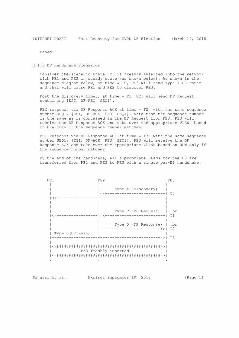
INTERNET DRAFT Fast Recovery for EVPN DF Election March 19, 2018
based.
3.1.6 DF Handshake Scenarios
Consider the scenario where PE3 is freshly inserted into the network with PE1 and PE2 in steady state (as shown below). As shown in the sequence diagram below, at time = T0, PE3 will send Type 4 ES route and that will cause PE1 and PE2 to discover PE3.
Post the discovery timer, at time = T1, PE3 will send DF Request containing [ESI, DF-REQ, SEQ1].
PE2 responds via DF Response ACK at time = T2, with the same sequence number SEQ1. [ESI, DF-ACK, PE3, SEQ1]. Note that the sequence number is the same as is contained in the DF Request from PE3. PE3 will receive the DF Response ACK and take over the appropriate VLANs based on HRW only if the sequence number matches.
PE1 responds via DF Response ACK at time = T3, with the same sequence number SEQ1; [ESI, DF-ACK, PE3, SEQ1]. PE3 will receive the DF Response ACK and take over the appropriate VLANs based on HRW only if the sequence number matches.
By the end of the handshake, all appropriate VLANs for the ES are transferred from PE1 and PE2 to PE3 with a single per-ES handshake.
PE1 PE2 PE3 | | | | | Type 4 (Discovery) | | |<<-------------------------| T0 |<<---------------------------------------------| | | | | | | | | Type C (DF Request) | .br |<<-----------------|<<-------------------------| T1 | | | | | Type D (DF Response) | .br | |------------------------->>| T2 | Type D(DF Resp) | | |--------------------------------------------->>| T3 | | | |<<###########################################>>| | PE3 freshly inserted | |<<###########################################>>| . . .
Sajassi et al. Expires September 19, 2018 [Page 11]

INTERNET DRAFT Fast Recovery for EVPN DF Election March 19, 2018
Consider the scenario where PE2 and PE3 are inserted simultaneously in the network where PE1 is in steady state (as shown below). PE2 and PE3 will send the Type 4 ES routes and start the discovery timer. This will cause PE1, PE2 and PE3 to discover each other.
PE2 and PE3 will then simultaneously and separately send DF Request. PE1 will receive these requests and respond to them.
To avoid any ambiguity, PE1 will explicitly specify in the DF Request route the destination for which the DF-ACK is meant for. That is why the responses from PE1 will contain [ES1, DF-ACK, PE2, SEQ] and [ESI, DF-ACK, PE3, SEQ] to specify that the response is meant for PE2 and PE3 respectively.
Upon receiving the Type-D response message, PE2 and PE3 will take over the respective VLANs.
PE1 PE2 PE3 | | | | | Type 4 (Discovery) | |<<-----------------| | T0 |<<-----------------|<<-------------------------| | | | | | | | | Type C (DF Request) | | |<<-------------------------| T1 | | | | Type C(DF Request)| | |<<-----------------| | T2 | | | | | Type D (DF Response) | |--------------------------------------------->>| T3 | | | |Type D(DF Response)| | |----------------->>| | T4 | | | |<<###########################################>>| | PE2 and PE3 inserted simultaneously | |<<###########################################>>| . . .
When PE3 is booted down or removed from the network, the routes formerly advertised by PE3 will be withdrawn, including the Type 4 route (as shown below). When PE1 and PE2 process the deletion of PE3’s Type 4 route, they will clean up any DF handshake state pertaining to PE3. This means that PE1 and PE2 will withdraw the DF Response routes that they had earlier sent with PE3 as the
Sajassi et al. Expires September 19, 2018 [Page 12]

INTERNET DRAFT Fast Recovery for EVPN DF Election March 19, 2018
destination.
PE1 PE2 PE3 | | | | | Type 4 Route Withdrawal | | |<<-------------------------| T0 |<<---------------------------------------------| | | | | PE2 purges Type D(DF Resp) sent to PE3 | T2 | | | | PE1 purges Type D(DF Resp) sent to PE3 | T3 | | | |<<###########################################>>| | PE3 booted down/removed from the network | |<<###########################################>>| . . .
3.1.7 Interoperability
Per redundancy group (per ES), for the DF election procedures to be globally convergent and unanimous, it is necessary that all the participating PEs agree on the DF Election algorithm to be used. It is, however, possible that some PEs continue to use the existing modulus based DF election and do not rely on the new handshake/sync procedures. PEs running an old versions of draft/RFC shall simply discard unrecognized new BGP extended communities.
A PE can indicate its willingness to support new Handshake and/or Time Synchronization capabilities by signaling them in the DF Election Extended Community defined in [DF-FRAMEWORK] sent along with the Ethernet-Segment Route (Type-4).
Considering that all the PE devices support the HRW election algorithm, but only a subset of them may have the capability of performing the handshake or synchronization mechanism. In such a situation, the following procedure are exercised.
If some PEs in the redundancy group signal both Handshake and Time Synchronization capabilities (both H & T set to 1), then Time Synchronization capability SHALL be chosen over Handshake capability with the HRW (or Preference-based) DF election algorithm.
If some PEs in the redundancy group signal Time Synchronization (T=1) but not Handshaking (H=0); whereas, some other PEs in the same redundancy group signal Handshaking (H=1) but not Time
Sajassi et al. Expires September 19, 2018 [Page 13]

INTERNET DRAFT Fast Recovery for EVPN DF Election March 19, 2018
Synchronization (T=0), then the PEs that have handshaking ability, SHALL perform HRW with handshaking among themselves and the PEs that Time Synchronization capability SHALL perform HRW (or Preference- based) with time synchronization among themselves.
If some PEs in the redundancy group don’t signal either Time Synchronization or Handshaking capabilities, then these PEs SHALL perform HRW (or Preference-based) with default timer based mechanism defined in [RFC 7432].
In the illustration below, PE1, PE2 and PE3 send their respective Type 4 routes indicating their DF capabilities at time T1, T2 and T3 respectively. Only PE2 and PE3 are Handshake capable, hence only PE2 and PE3 partake in DF Handshaking procedure described here at time T4 and T5. PE1 on the other hand, runs the DF election timer and takes over the DF role upon timer expiry at time T6.
PE1 PE2 PE3.br | | | | | | | Type 4 (0x0 Default Capability) | |----------------->>|------------------------->>| T1 | | | | Type 4 (H=1 Handshake Capable) | |<<-----------------|------------------------->>| T2 | | | | Type 4 (H=1 Handshake Capable) | |<<-----------------|<<-------------------------| T3 | | | | | | | | Type C (DF Request) | | |<<-------------------------| T4 | | | | | Type D (DF Response) | | |------------------------->>| T5 | PE1 Timer Expiry (DF Takeover) | T6 |<<###########################################>>| | Only PE2 and PE3 Handshake Capable | |<<###########################################>>| . . .
3.2 DF Election Synchronization Solution
Sajassi et al. Expires September 19, 2018 [Page 14]

INTERNET DRAFT Fast Recovery for EVPN DF Election March 19, 2018
If all PE devices attached to a given Ethernet Segment are clock- synchronized with each other, then the above handshaking procedures can be simplified and packet loss can be reduced from BGP-propagation time (between recovered PE and the DF PE) to very small time (e.g., milliseconds or less).
The simplified procedure is as follow:
First, the DF election procedure, described in RFC7432, is applied as before.
All PEs attached to a given Ethernet-Segment are clock-synchronized; using a networking protocol for clock synchronization (e.g. NTP, PTP, etc).
Newly inserted device PE or during failure recovery of a PE, that PE communicates the current time to peering partners plus the remaining peering timer time left. This constitute an "endtime" as see from local PE. That "endtime" is called "Service Carving Time" (SCT).
A new BGP Extended Community is advertised along with RT-4 to communicate to other partners the Service Carving Time.
Upon reception of that new BGP Extended Community, partner PEs know exactly its carving time. The notion of skew is introduced to eliminate any potential duplicate traffic or loops. They add a skew (default = -10ms) to the Service Carving Time to enforce this; basically partner PEs must carve first.
To summarize, all peering PEs carve almost simultaneously at the time announced by newly added / recovered PE. The newly added/recovered PE initiates the SCT, carves immediately on peering timer expiry. Other PE receiving RT-4 with a SCT BGP ExtComm, carve shortly before "SCT time".
3.2.3 Advantages
There are multiples advantages of using the approach. Here is a non- exhaustive list:
- A simple uni-directional signaling is all needed
- Backwards-compatible: old versions of draft/RFC shall simply discard unrecognized new SCT BGP ExtComm
- Multiple DF Election algorithms can be supported: * RFC7432’s default ordered list ordinal algorithm (modulo)
Sajassi et al. Expires September 19, 2018 [Page 15]

INTERNET DRAFT Fast Recovery for EVPN DF Election March 19, 2018
* HRW in [DF-FRAMEWORK], etc - Independent of BGP transmission delay for RT-4 - Solutions is agnostic of the time synchronization mechanisms (e.g. NTP, PTP, ...)
3.2.4 Interoperability
Per redundancy group, for the DF election procedures to be globally convergent and unanimous, it is necessary that all the participating PEs agree on the DF Election algorithm to be used. It is, however, possible that some PEs continue to use the existing modulus based DF election and do not rely on the new SCT BGP extended community. PEs running an baseline DF election mechanism shall simply discard unrecognized new SCT BGP extended community.
A PE can indicate its willingness to support clock-synched carving by signaling the new SCT BGP extended community along with the Ethernet- Segment Route (Type-4).
3.2.5 BGP Encoding
A new BGP extended community needs to be defined to communicate the Service Carving Expected Timestamp for each Ethernet Segment.
A new transitive extended community where the Type field is 0x06, and the Sub-Type is <to be defined> is advertised along with Ethernet Segment route. Timestamp for expected Service carving is encoded as a 8-octet value as follows:
1 2 3 0 1 2 3 4 5 6 7 8 9 0 1 2 3 4 5 6 7 8 9 0 1 2 3 4 5 6 7 8 9 0 1 +-+-+-+-+-+-+-+-+-+-+-+-+-+-+-+-+-+-+-+-+-+-+-+-+-+-+-+-+-+-+-+-+ | Type=0x06 | Sub-Type(TBD) | Timestamp(upper 16)| +-+-+-+-+-+-+-+-+-+-+-+-+-+-+-+-+-+-+-+-+-+-+-+-+-+-+-+-+-+-+-+-+ | Timestamp (lower 32) | +-+-+-+-+-+-+-+-+-+-+-+-+-+-+-+-+-+-+-+-+-+-+-+-+-+-+-+-+-+-+-+-+
This document introduces a new flag called "T" (for Time Synchronization) to the bitmap field of the DF Election Extended Community defined in [DF-FRAMWORK].
Sajassi et al. Expires September 19, 2018 [Page 16]

INTERNET DRAFT Fast Recovery for EVPN DF Election March 19, 2018
1 2 3 0 1 2 3 4 5 6 7 8 9 0 1 2 3 4 5 6 7 8 9 0 1 2 3 4 5 6 7 8 9 0 1 +-+-+-+-+-+-+-+-+-+-+-+-+-+-+-+-+-+-+-+-+-+-+-+-+-+-+-+-+-+-+-+-+ | Type=0x06 | Sub-Type(0x06)| DF Type |P|A|H|T| Bitmap| +-+-+-+-+-+-+-+-+-+-+-+-+-+-+-+-+-+-+-+-+-+-+-+-+-+-+-+-+-+-+-+-+ | Reserved = 0 | +-+-+-+-+-+-+-+-+-+-+-+-+-+-+-+-+-+-+-+-+-+-+-+-+-+-+-+-+-+-+-+-+
T: This flag is located in bit position 27 as shown above. When set to 1, it indicates the desire to use Time Synchronization capability with the rest of the PEs in the ES. This capability is used in conjunction with the agreed upon DF Type (DF Election Type). For example if all the PEs in the ES indicated that they have Time Synchronization capability and they want the DF type be of HRW, then HRW algorithm is used in conjunction with this capability.
3.2.6 Note on NTP-based synchronization
The 64-bit timestamp used by NTP protocol consists of a 32-bit part for seconds and a 32-bit part for fractional second. Giving a time scale that rolls over every 2^32 seconds (136 years) and a theoretical resolution of 2^32 seconds (233 picoseconds). The recommendation is to keep the top 32 bits and carry lower MSB 16 bits of fractional second.
3.2.7 An example
Let’s take figure 1 as an example where initially PE2 had failed and PE1 had taken over.
Based on RFC-7432:
- Initial state: PE1 is in steady-state, PE2 is recovering - PE2 recovers at (absolute) time t=99 - PE2 advertises RT-4 (sent at t=100) to partner PE1. - PE2, it starts its 3sec peering timer as per RFC7432 - PE1 carves immediately on RT-4 reception. PE2 carves at time t=103.
With following procedure, there is a high chance to generate a traffic black hole or traffic loop. The peering timer value has a direct effect of this behavior. A short peering timer may generate loop whereas a long peering timer provide a prolong blackout.
Based on the SCT approach:
- Initial state: PE1 is in steady-state, PE2 is recovering
Sajassi et al. Expires September 19, 2018 [Page 17]

INTERNET DRAFT Fast Recovery for EVPN DF Election March 19, 2018
- PE2 recovers at (absolute) time t=99 - PE2 advertises RT-4 (sent at t=100) with target SCT value t=103 to partner PE1 - PE2 starts its 3sec peering timer as per RFC7432 - Both PE1 and PE2 carves at (absolute) time t=103; In fact, PE1 should carve slightly before PE2 (skew).
Using SCT approach, the effect of the peering timer is gone. Also, the BGP RT-4 transmission delay (from PE2 to PE1) becomes a no-op.
4 Acknowledgement Authors would like to acknowledge helpful comments and contributions of Satya Mohanty and Luc Andre Burdet.
5 Security Considerations
The mechanisms in this document use EVPN control plane as defined in [RFC7432]. Security considerations described in [RFC7432] are equally applicable. This document uses MPLS and IP-based tunnel technologies to support data plane transport. Security considerations described in [R7432] and in [ietf-evpn-overlay] are equally applicable.
6 IANA Considerations
Allocation of Extended Community Type and Sub-Type for EVPN.
7 References
7.1 Normative References
[KEYWORDS] Bradner, S., "Key words for use in RFCs to Indicate Requirement Levels", BCP 14, RFC 2119, March 1997.
[RFC7432] Sajassi et al., "BGP MPLS Based Ethernet VPN", February, 2015.
[DF-FRAMEWORK] Rabadan, Mohanty et al., "Framework for EVPN Designated Forwarder Election Extensibility", draft-ietf- bess-evpn-df-election-framework-00, work in progress, March 5, 2018.
7.2 Informative References
Sajassi et al. Expires September 19, 2018 [Page 18]

INTERNET DRAFT Fast Recovery for EVPN DF Election March 19, 2018
Authors’ Addresses
Ali Sajassi Cisco Email: [email protected]
Gaurav Badoni Cisco Email: [email protected]
Patrice Brissette Cisco Email: [email protected]
Dhananjaya Rao Cisco Email: [email protected]
John Drake Juniper Email: [email protected]
Jorge Rabadan Juniper Email: [email protected]
Sajassi et al. Expires September 19, 2018 [Page 19]

BESS WorkGroup Ali. SajassiInternet-Draft Mankamana. MishraIntended status: Standards Track Samir. ThoriaExpires: September 4, 2018 Cisco Systems Jorge. Rabadan Nokia John. Drake Juniper Networks March 3, 2018
Per multicast flow Designated Forwarder Election for EVPN draft-sajassi-bess-evpn-per-mcast-flow-df-election-00
Abstract
[RFC7432] describes mechanism to elect designated forwarder (DF) at the granularity of (ESI, EVI) which is per VLAN (or per group of VLANs in case of VLAN bundle or VLAN-aware bundle service). However, the current level of granularity of per-VLAN is not adequate for some of applications. [I-D.ietf-bess-evpn-ac-df] and [I-D.ietf-bess-evpn-df-election] improves base line DF election. This document is an extension to HRW base drafts ([I-D.ietf-bess-evpn-ac-df] and [I-D.ietf-bess-evpn-df-election]) and further enhances HRW algorithm to do DF election at the granularity of (ESI, VLAN, Mcast flow).
Status of This Memo
This Internet-Draft is submitted in full conformance with the provisions of BCP 78 and BCP 79.
Internet-Drafts are working documents of the Internet Engineering Task Force (IETF). Note that other groups may also distribute working documents as Internet-Drafts. The list of current Internet- Drafts is at https://datatracker.ietf.org/drafts/current/.
Internet-Drafts are draft documents valid for a maximum of six months and may be updated, replaced, or obsoleted by other documents at any time. It is inappropriate to use Internet-Drafts as reference material or to cite them other than as "work in progress."
This Internet-Draft will expire on September 4, 2018.
Sajassi, et al. Expires September 4, 2018 [Page 1]

Internet-DraPer multicast flow Designated Forwarder Election March 2018
Copyright Notice
Copyright (c) 2018 IETF Trust and the persons identified as the document authors. All rights reserved.
This document is subject to BCP 78 and the IETF Trust’s Legal Provisions Relating to IETF Documents (https://trustee.ietf.org/license-info) in effect on the date of publication of this document. Please review these documents carefully, as they describe your rights and restrictions with respect to this document. Code Components extracted from this document must include Simplified BSD License text as described in Section 4.e of the Trust Legal Provisions and are provided without warranty as described in the Simplified BSD License.
Table of Contents
1. Introduction . . . . . . . . . . . . . . . . . . . . . . . . 2 2. Terminology . . . . . . . . . . . . . . . . . . . . . . . . . 4 3. The DF Election Extended Community . . . . . . . . . . . . . 4 4. HRW base per multicast flow EVPN DF election . . . . . . . . 6 4.1. DF election for IGMP (S,G) membership request . . . . . . 6 4.2. DF election for IGMP (*,G) membership request . . . . . . 6 4.3. Default DF election procedure . . . . . . . . . . . . . . 7 5. Procedure to use per multicast flow DF election algorithm . . 7 6. Triggers for DF re-election . . . . . . . . . . . . . . . . . 9 7. Protocol Considerations . . . . . . . . . . . . . . . . . . . 9 8. Security Considerations . . . . . . . . . . . . . . . . . . . 10 9. IANA Considerations . . . . . . . . . . . . . . . . . . . . . 10 10. Acknowledgement . . . . . . . . . . . . . . . . . . . . . . . 10 11. Normative References . . . . . . . . . . . . . . . . . . . . 10 Authors’ Addresses . . . . . . . . . . . . . . . . . . . . . . . 11
1. Introduction
EVPN based All-Active multi-homing is becoming the basic building block for providing redundancy in next generation data center deployments as well as service provider access/aggregation network. [RFC7432] defines role of a designated forwarder as the node in the redundancy group that is responsible to forward Broadcast, Unknown unicast, Multicast (BUM) traffic on that Ethernet Segment (CE device or network) in an All-Active multi-homing.
This DF election mechanism allows selecting a DF at the granularity of (ES, VLAN) or (ES, VLAN bundle) for Broadcast, Unknown Unicast, or Multicast (BUM) traffic. Though [I-D.ietf-bess-evpn-ac-df] and [I-D.ietf-bess-evpn-df-election] improves the default DF election procedure , still it does not fit well for some of service provider
Sajassi, et al. Expires September 4, 2018 [Page 2]

Internet-DraPer multicast flow Designated Forwarder Election March 2018
residential application, where whole multicast traffic is delivered on single VLAN.
(Multicast sources) | | +---+ |CE4| +---+ | | +-----+-----+ +------------| PE-1 |------------+ | | | | | +-----------+ | | | | EVPN | | | | | | (DF) (NDF)| +-----------+ +-----------+ | |EVI-1| | | |EVI-1| | | PE-2 |------------------------| PE-3 | +-----------+ +-----------+ AC1 \ / AC2 \ / \ ESI-1 / \ / \ / +---------------+ | CE2 | +---------------+ | | (Multiple receivers)
Figure 1: Multi-homing Network of EVPN for IPTV deployments
Consider the above topology, which shows residential deployment scenario, where multiple receivers are behind all active multihoming segment. All of the multicast traffic is provisioned on EVI-1. Assume PE-2 get elected as DF. According to [RFC7432] PE-2 will be responsible for forwarding multicast traffic to that Ethernet segment.
Sajassi, et al. Expires September 4, 2018 [Page 3]

Internet-DraPer multicast flow Designated Forwarder Election March 2018
o Forcing sole data plane forwarding responsibility on the PE-2 proves a limitation in the current DF election mechanism. In topology at Figure 1 would always have only one of the PE to be elected as DF irrespective of which current DF election mechanism is in use (defined in [RFC7432] or [I-D.ietf-bess-evpn-ac-df] and [I-D.ietf-bess-evpn-df-election]).
o In the above deployment we have to consider one more factor, Network bandwidth is shared between multicast and unicast flow. At any given point of time if AC1 already has unicast traffic flow which is taking good amount of network bandwidth. we would have very limited bandwidth available for multicast flows. Even though PE-3 to CE2 (AC2) has not been used much, still we would end up having limitation about how much multicast can flow though AC1.
In this document, we propose an extension to HRW base drafts to allow DF election at the granularity of (ESI, VLAN, Mcast flow) which would allow multicast flows to be distributed among redundancy group PE’s to share the load.
2. Terminology
The key words "MUST", "MUST NOT", "REQUIRED", "SHALL", "SHALL NOT", "SHOULD", "SHOULD NOT", "RECOMMENDED", "MAY", and "OPTIONAL" in this document are to be interpreted as described in [RFC2119] .
With respect to EVPN, this document follows the terminology that has been defined in [RFC7432] and [RFC4601] for multicast terminology.
3. The DF Election Extended Community
[I-D.ietf-bess-evpn-ac-df] and [I-D.ietf-bess-evpn-df-election] defines extended community, which would be used for PE’s in redundancy group to come to an agreement about which DF election procedures is supported. A PE can notify other participating PE’s in redundancy group about its willingness to support Per multicast flow base DF election capability by signaling a DF election extended community along with Ethernet-Segment Route (Type-4). current proposal extends the existing extended community defined in [I-D.ietf-bess-evpn-ac-df] and [I-D.ietf-bess-evpn-df-election]. This draft defines new a DF type.
o DF type (1 octet) - Encodes the DF Election algorithm values (between 0 and 255) that the advertising PE desires to use for the ES.
* Type 0: Default DF Election algorithm, or modulus-based algorithms in [RFC7432].
Sajassi, et al. Expires September 4, 2018 [Page 4]

Internet-DraPer multicast flow Designated Forwarder Election March 2018
* Type 1: HRW algorithm defined in [I-D.ietf-bess-evpn-ac-df] and [I-D.ietf-bess-evpn-df-election]
* Type 4: HRW base per multicast flow DF election (explained in this document)
* Type 5 - 254: Unassigned
* Type 255: Reserved for Experimental Use.
o The [I-D.ietf-bess-evpn-ac-df] and [I-D.ietf-bess-evpn-df-election] describes encoding of capabilities associated to the DF election algorithm using Bitmap field. When these capabilities bits are set along with the DF type-4, then these capabilities need to be interpreted in context of this new DF type-4. For example consider a scenario where all PEs in the same redundancy group (same ES) can support both AC-DF and DF type-4 and thus they receive such indications from the other PEs in the ES. In this scenario, if a VLAN is not active in a PE, then the DF election procedure on all PEs in the ES should factor that in and exclude that PE in the DF election per multicast flow.
o A PE SHOULD attach the DF election Extended Community to ES route and Extended Community MUST be sent if the ES is locally configured for DF type Per Multicast flow DF election. Only one DF Election Extended community can be sent along with an ES route.
o When a PE receives the ES Routes from all the other PE’s for the ES, it check if all of other PE’s have advertised their capability about Per multicast flow DF election procedure. If all of them have advertised capability, it performs DF election based on Per multicast flow procedure. But if
* There is at least one PE which advertised route-4 ( AD per ES Route) which does not indicates its capability to perform Per multicast flow DF election. OR
* There is at least one PE signals single active in the AD per ES route
It MUST be considered as an indication to support of only Default DF election [RFC7432] and DF election procedure in [RFC7432] MUST be used.
Sajassi, et al. Expires September 4, 2018 [Page 5]

Internet-DraPer multicast flow Designated Forwarder Election March 2018
4. HRW base per multicast flow EVPN DF election
This document is an extension of [I-D.ietf-bess-evpn-ac-df] and [I-D.ietf-bess-evpn-df-election], so this draft does not repeat description of HRW algorithm itself.
EVPN PE does the discovery of redundancy group based on [RFC7432]. If redundancy group consists of N EVPN PE nodes. Then after the discovery all PEs build an unordered list of IP address of all the nodes in redundancy group. Procedure defined in this draft does not require PE’s to be ordered list.Address [i] denotes the IP address of i’th EVPN PE in redundancy group where (0 < i <= N ).
4.1. DF election for IGMP (S,G) membership request
The DF is the PE who has maximum affinity for (S, G, V, ESI) where
o S - Multicast Source
o G - Multicast Group
o V - Vlan ID for Ethernet Tag V.
o ESI - Ethernet Segment Identifier
In case of tie choose the PE whose IP address is numerically least.
The affinity of PE(i) to (S,G,VLAN ID, ESI) is calculated by function, affinity (S,G,V, ESI, Address(i)), where (0 < i <= N), PE(i) is the PE at ordinal i, address(i) is the IP address of PE at ordinal i
o affinity (S,G,V, ESI, Address(i)) = (1103515245. ((1103515245.Address(i) + 12345) XOR D(S,G,V,ESI))+12345) (mod 2^31)
o D(S,G,V, ESI) = CRC_32(S,G,V, ESI).
Here D(S,G,V,ESI) is the 32-bit digest (CRC_32) of the Source IP, Group IP, Vlan ID for Ethernet Tag V. Source and Group IP address length does not matter as only the lower order 31 bits are modulo significant.
4.2. DF election for IGMP (*,G) membership request
In case of IGMP membership request where source is not known. The DF is the PE which has maximum affinity for (G,V, ESI) where
Sajassi, et al. Expires September 4, 2018 [Page 6]

Internet-DraPer multicast flow Designated Forwarder Election March 2018
o G - Multicast Group
o V - Vlan ID for Ethernet Tag V.
o ESI - Ethernet Segment Identifier
In case of tie choose the PE whose IP address is numerically least.
The affinity of PE(i) to (G,V, ESI) is calculated by function, affinity (G,V, ESI, Address(i)), where (0 < i <= N), PE(i) is the PE at ordinal i, address(i) is the IP address of PE at ordinal i
o affinity (G, V, ESI, Address(i)) = (1103515245. ((1103515245.Address(i) + 12345) XOR D(G,V,ESI))+12345) (mod 2^31)
o D(G,V, ESI) = CRC_32(G,V, ESI).
Here D(G,V,ESI) is the 32-bit digest (CRC_32) of the Group IP, Vlan ID for Ethernet Tag V. Source and Group IP address length does not matter as only the lower order 31 bits are modulo significant.
4.3. Default DF election procedure
Even if all of the PE’s indicate their availability to participate in per multicast flow DF election procedure, there is need to have default DF election algorithm. Since Per multicast flow DF election is applicable for only those multicast flows for which PE has received membership request. For other BUM traffic, forwarding plane need default DF election procedure. And we use HRW based DF election procedure as default one in these cases which is defined in [I-D.ietf-bess-evpn-ac-df] and [I-D.ietf-bess-evpn-df-election].
5. Procedure to use per multicast flow DF election algorithm
Sajassi, et al. Expires September 4, 2018 [Page 7]

Internet-DraPer multicast flow Designated Forwarder Election March 2018
Multicast Source | | | | +---------+ +--------------+ PE-4 +--------------+ | | | | | +---------+ | | | | EVPN CORE | | | | | | | +---------+ +---------+ +---------+ | PE-1 +--------+ PE-2 +---------+ PE-3 | | EVI-1 | | EVI-1 | | EVI-1 | +---------+ +---------+ +---------+ |__________________|___________________| AC-1 ESI-1 | AC-2 AC-3 +---------+ | CE-1 | | | +---------+ | | | | Multicast Receivers
Figure-2 : Multihomed network
Figure-2 shows multihomed network. Where EVPN PE-1, PE-2, PE-3 are multihomed to CE-1. Multiple multicast receivers are behind all active multihoming segment.
1. PE’s connected to the same Ethernet segment can automatically discover each other through exchange of the Ethernet Segment Route. This draft does not change any of this procedure, it still uses procedure defined in [RFC7432].
2. Each of the PE’s in redundancy group advertise Ethernet segment route with extended community indicating their ability to participate in per multicast flow DF election procedure. Since Per multicast flow would not be applicable unless PE learns about membership request from receiver, there is need to have default DF election among PE’s in redundancy group for BUM traffic. In initial phase we use Section 4.3 DF election procedure.
Sajassi, et al. Expires September 4, 2018 [Page 8]

Internet-DraPer multicast flow Designated Forwarder Election March 2018
3. When receiver starts sending membership request for (s1,g1) where s1 is multicast source address and g1 is multicast group address, CE-1 could hash membership request (IGMP join) to any of the PE’s in redundancy group. Lets consider it is hashed to PE-2. [I-D.ietf-bess-evpn-igmp-mld-proxy] defines procedure to sync IGMP join state among redundancy group of PE’s. Now each of the PE would have information about membership request (s1,g1) and each of them run DF election procedure Section 4.1 to elect DF among participating PE’s in redundancy group. Consider PE-2 gets elected as DF for multicast flow (s1,g1).
1. PE-1 forwarding state would be nDF for flow (s1,g1) and DF for rest other BUM traffic.
2. PE-2 forwarding state would be DF for flow (s1,g1) and nDF for rest other BUM traffic.
3. PE-3 forwarding state would be nDF for flow (s1,g1) and rest other BUM traffic.
4. As and when new multicast membership request comes, same procedure as above would continue.
6. Triggers for DF re-election
There are multiple triggers which can cause DF re-election. Some of the triggers could be
1. Local ES going down due to physical failure or configuration change
2. Detection of new PE through ES route.
3. AC going up / down
This document does not provide any new mechanism to handle DF re- election procedure. it does uses existing mechanism defined in [RFC7432]. When ever either of trigger occur, DF re-election would be done. and all of the flows would be redistributed among existing PE’s in redundancy group for ES.
7. Protocol Considerations
More details to be added in next version.
Sajassi, et al. Expires September 4, 2018 [Page 9]

Internet-DraPer multicast flow Designated Forwarder Election March 2018
8. Security Considerations
The same Security Considerations described in [RFC7432] are valid for this document.
9. IANA Considerations
There are no new IANA considerations in this document.
10. Acknowledgement
11. Normative References
[HRW1999] IEEE, "Using name-based mappings to increase hit rates", IEEE HRW, February 1998.
[I-D.ietf-bess-evpn-ac-df] Rabadan, J., Nagaraj, K., Sathappan, S., Prabhu, V., Liu, A., and W. Lin, "AC-Influenced Designated Forwarder Election for EVPN", draft-ietf-bess-evpn-ac-df-03 (work in progress), January 2018.
[I-D.ietf-bess-evpn-df-election] [email protected], s., Patel, K., Sajassi, A., Drake, J., and T. Przygienda, "A new Designated Forwarder Election for the EVPN", draft-ietf-bess-evpn-df-election-03 (work in progress), October 2017.
[I-D.ietf-bess-evpn-igmp-mld-proxy] Sajassi, A., Thoria, S., Patel, K., Yeung, D., Drake, J., and W. Lin, "IGMP and MLD Proxy for EVPN", draft-ietf- bess-evpn-igmp-mld-proxy-00 (work in progress), March 2017.
[RFC2119] Bradner, S., "Key words for use in RFCs to Indicate Requirement Levels", BCP 14, RFC 2119, DOI 10.17487/RFC2119, March 1997, <https://www.rfc-editor.org/info/rfc2119>.
[RFC4601] Fenner, B., Handley, M., Holbrook, H., and I. Kouvelas, "Protocol Independent Multicast - Sparse Mode (PIM-SM): Protocol Specification (Revised)", RFC 4601, DOI 10.17487/RFC4601, August 2006, <https://www.rfc-editor.org/info/rfc4601>.
Sajassi, et al. Expires September 4, 2018 [Page 10]

Internet-DraPer multicast flow Designated Forwarder Election March 2018
[RFC7432] Sajassi, A., Ed., Aggarwal, R., Bitar, N., Isaac, A., Uttaro, J., Drake, J., and W. Henderickx, "BGP MPLS-Based Ethernet VPN", RFC 7432, DOI 10.17487/RFC7432, February 2015, <https://www.rfc-editor.org/info/rfc7432>.
Authors’ Addresses
Ali Sajassi Cisco Systems 821 Alder Drive, MILPITAS, CALIFORNIA 95035 UNITED STATES
Email: [email protected]
Mankamana Mishra Cisco Systems 821 Alder Drive, MILPITAS, CALIFORNIA 95035 UNITED STATES
Email: [email protected]
Samir Thoria Cisco Systems 821 Alder Drive, MILPITAS, CALIFORNIA 95035 UNITED STATES
Email: [email protected]
Jorge Rabadan Nokia 777 E. Middlefield Road Mountain View, CA 94043 UNITED STATES
Email: [email protected]
John Drake Juniper Networks
Email: [email protected]
Sajassi, et al. Expires September 4, 2018 [Page 11]

Internet Working Group A. SajassiInternet Draft P. BrissetteCategory: Standards Track Cisco R. Schell Verizon J. Drake Juniper J. Rabadan Nokia
Expires: August 26, 2016 February 26, 2018
EVPN Virtual Ethernet Segment draft-sajassi-bess-evpn-virtual-eth-segment-03
Status of this Memo
This Internet-Draft is submitted to IETF in full conformance with the provisions of BCP 78 and BCP 79.
Internet-Drafts are working documents of the Internet Engineering Task Force (IETF), its areas, and its working groups. Note that other groups may also distribute working documents as Internet-Drafts.
Internet-Drafts are draft documents valid for a maximum of six months and may be updated, replaced, or obsoleted by other documents at any time. It is inappropriate to use Internet-Drafts as reference material or to cite them other than as "work in progress."
The list of current Internet-Drafts can be accessed at http://www.ietf.org/1id-abstracts.html
The list of Internet-Draft Shadow Directories can be accessed at http://www.ietf.org/shadow.html
Copyright and License Notice
Copyright (c) 2014 IETF Trust and the persons identified as the document authors. All rights reserved.
This document is subject to BCP 78 and the IETF Trust’s Legal Provisions Relating to IETF Documents (http://trustee.ietf.org/license-info) in effect on the date of publication of this document. Please review these documents carefully, as they describe your rights and restrictions with respect
Sajassi et al. Expires August 26, 2018 [Page 1]

INTERNET DRAFT PBB-EVPN February 26, 2018
to this document. Code Components extracted from this document must include Simplified BSD License text as described in Section 4.e of the Trust Legal Provisions and are provided without warranty as described in the Simplified BSD License.
Abstract
EVPN and PBB-EVPN introduce a family of solutions for multipoint Ethernet services over MPLS/IP network with many advanced capabilities among which their multi-homing capabilities. These solutions define two types of multi-homing for an Ethernet Segment (ES): 1) Single-Active and 2) All-Active, where an Ethernet Segment is defined as a set of links between the multi-homed device/network and the set of PE devices that they are connected to.
Some Service Providers want to extend the concept of the physical links in an ES to Ethernet Virtual Circuits (EVCs) where many of such EVCs can be aggregated on a single physical External Network-to- Network Interface (ENNI). An ES that consists of a set of EVCs instead of physical links is referred to as a virtual ES (vES). This draft describes the requirements and the extensions needed to support vES in EVPN and PBB-EVPN.
Conventions
The key words "MUST", "MUST NOT", "REQUIRED", "SHALL", "SHALL NOT", "SHOULD", "SHOULD NOT", "RECOMMENDED", "MAY", and "OPTIONAL" in this document are to be interpreted as described in RFC 2119.
Table of Contents
1. Introduction . . . . . . . . . . . . . . . . . . . . . . . . . 4 1.1 Virtual Ethernet Segments in Access Ethernet Networks . . . 4 1.2 Virtual Ethernet Segments in Access MPLS Networks . . . . . 5 2. Terminology . . . . . . . . . . . . . . . . . . . . . . . . . . 7 3. Requirements . . . . . . . . . . . . . . . . . . . . . . . . . 8 3.1. Single-Homed & Multi-Homed Virtual Ethernet Segments . . . 8 3.2. Scalability . . . . . . . . . . . . . . . . . . . . . . . . 8 3.3. Local Switching . . . . . . . . . . . . . . . . . . . . . . 9 3.4. EVC Service Types . . . . . . . . . . . . . . . . . . . . . 9 3.5. Designated Forwarder (DF) Election . . . . . . . . . . . . 10 3.6. OAM . . . . . . . . . . . . . . . . . . . . . . . . . . . . 10 3.7. Failure & Recovery . . . . . . . . . . . . . . . . . . . . 10 3.8. Fast Convergence . . . . . . . . . . . . . . . . . . . . . 11 4. Solution Overview . . . . . . . . . . . . . . . . . . . . . . . 11 4.1. EVPN DF Election for vES . . . . . . . . . . . . . . . . . 12 5. Failure Handling & Recovery . . . . . . . . . . . . . . . . . . 14
Sajassi et al. Expires August 26, 2018 [Page 2]

INTERNET DRAFT PBB-EVPN February 26, 2018
5.1. Failure Handling for Single-Active vES in EVPN . . . . . . 15 5.2. EVC Failure Handling for Single-Active vES in PBB-EVPN . . 15 5.3. Port Failure Handling for Single-Active vES’s in EVPN . . . 16 5.4. Port Failure Handling for Single-Active vES’s in PBB-EVPN . 17 5.5. Fast Convergence in PBB-EVPN . . . . . . . . . . . . . . . 18 6. BGP Encoding . . . . . . . . . . . . . . . . . . . . . . . . . 20 6.1. I-SID Extended Community . . . . . . . . . . . . . . . . . 20 7. Acknowledgements . . . . . . . . . . . . . . . . . . . . . . . 20 8. Security Considerations . . . . . . . . . . . . . . . . . . . . 21 9. IANA Considerations . . . . . . . . . . . . . . . . . . . . . . 21 10. Intellectual Property Considerations . . . . . . . . . . . . . 21 11. Normative References . . . . . . . . . . . . . . . . . . . . . 21 12. Informative References . . . . . . . . . . . . . . . . . . . . 21 13. Authors’ Addresses . . . . . . . . . . . . . . . . . . . . . . 21
Sajassi et al. Expires August 26, 2018 [Page 3]

INTERNET DRAFT PBB-EVPN February 26, 2018
1. Introduction
[EVPN] and [PBB-EVPN] introduce a family of solutions for multipoint Ethernet services over MPLS/IP network with many advanced capabilities among which their multi-homing capabilities. These solutions define two types of multi-homing for an Ethernet Segment (ES): 1) Single-Active and 2) All-Active, where an Ethernet Segment is defined as a set of links between the multi-homed device/network and the set of PE devices that they are connected to.
This document extends the Ethernet Segment concept so that an ES can be associated to a set of EVCs or other objects such as MPLS Label Switch Paths (LSP) or Pseudowires (PW).
1.1 Virtual Ethernet Segments in Access Ethernet Networks
Some Service Providers (SPs) want to extend the concept of the physical links in an ES to Ethernet Virtual Circuits (EVCs) where many of such EVCs can be aggregated on a single physical External Network-to-Network Interface (ENNI). An ES that consists of a set of EVCs instead of physical links is referred to as a virtual ES (vES). Figure below depicts two PE devices (PE1 and PE2) each with an ENNI where a number of vES’s are aggregated on - each of which through its associated EVC.
Sajassi et al. Expires August 26, 2018 [Page 4]

INTERNET DRAFT PBB-EVPN February 26, 2018
Carrier Ethernet +-----+ Network | CE11|EVC1 +---------+ +-----+ \ | | +---+ Cust. A \-0=========0--ENNI1| | +-----+ | | ENNI1| | +-------+ +---+ | CE12|EVC2--0=========0--ENNI1|PE1|---| | | | +-----+ | | ENNI1| | | |---|PE3|- | ==0--ENNI1| | |IP/MPLS| | | \ +---+ +-----+ | / | +---+ |Network| +---+ \-| | | CE22|EVC3--0==== / | | | |CE4| +-----+ | X | | | +---+ | | | / \ | +---+ | | | | /-| | +-----+ -0=== ===0--ENNI2| | | |---|PE4|-/ +---+ | CE3 |EVC4/ | | ENNI2|PE2|---| | | | | |EVC5--0=========0--ENNI2| | +-------+ +---+ +-----+ | | +---+ Cust. C +---------+ /\ /\ || || ENNI EVCs Interface <--------802.1Q----------> <-802.1Q->
Figure 1: DHD/DHN (both SA/AA) and SH on same ENNI
E-NNIs are commonly used to reach off-network / out-of-franchise customer sites via independent Ethernet access networks or third- party Ethernet Access Providers (EAP) (see above figure). E-NNIs can aggregate traffic from hundreds to thousands of vES’s; where, each vES is represented by its associated EVC on that ENNI. As a result, ENNIs and their associated EVCs are a key element of SP off-networks that are carefully designed and closely monitored.
In order to meet customer’s Service Level Agreements (SLA), SPs build redundancy via multiple E-PEs / ENNIs (as shown in figure above) where a given vES can be multi-homed to two or more PE devices (on two or more ENNIs) via their associated EVCs. Just like physical ES’s in [EVPN] and [PBB-EVPN] solutions, these vES’s can be single-homed or multi-homed ES’s and when multi-homed, then can operate in either Single-Active or All-Active redundancy modes. In a typical SP off- network scenario, an ENNI can be associated with several thousands of single-homed vES’s, several hundreds of Single-Active vES’s and it may also be associated with tens or hundreds of All-Active vES’s.
1.2 Virtual Ethernet Segments in Access MPLS Networks
Sajassi et al. Expires August 26, 2018 [Page 5]

INTERNET DRAFT PBB-EVPN February 26, 2018
Other Service Providers (SPs) want to extend the concept of the physical links in an ES to individual Pseudowires (PW) or to MPLS Label Switched Paths (LSPs) per [EVPN-VPWS] in Access MPLS networks. Figure 2 illustrates this concept.
MPLS Aggregation Network +-----+ +----------------+ <----EVPN Network-----> | CE11|EVC1 | | +-----+ \+AG1--+ PW1 +-----+ Cust. A -0----|===========| | +-----+ | ---+===========| | +-------+ +---+ | CE12|EVC2-0/ | PW2 /\ | PE1 +---+ | | | +-----+ ++---+ ==||=| | | +---+PE3+- | //=||=| | |IP/MPLS| | | \ +---+ | // \/ ++----+ |Network| +---+ \-+ | +-----+EVC3 | PW3// LSP1 | | | |CE4| | CE13| +AG2--+===/PW4 | | | +---+ | | +-----+ 0 |=== /\ ++----+ | | | | /-+ | 0 |==PW5===||=| | | +---+PE4+-/ +---+ +-----+ /++---+==PW6===||=| PE2 +---+ | | | | CE14|EVC4 | \/ | | +-------+ +---+ +-----+ | LSP2+-----+ Cust. C +----------------+ /\ || EVCs <--802.1Q---><------MPLS-------> <-802.1Q->
Figure 2: DHN and SH on Access MPLS networks
In some cases, Service Providers use Access MPLS Networks that belong to separate administrative entities or third parties as a way to get access to the their own IP/MPLS network infrastructure. This is the case illustrated in Figure 2.
An ES is defined as a set of individual PWs if they cannot be aggregated into a common LSP. If the aggregation of PWs is possible, the ES can be associated to an LSP in a given PE. In the example of Figure 2, EVC3 is connected to a VPWS instance in AG2 that is connected to PE1 and PE2 via PW3 and PW5 respectively. EVC4 is connected to a separate VPWS instance on AG2 that gets connected to
Sajassi et al. Expires August 26, 2018 [Page 6]

INTERNET DRAFT PBB-EVPN February 26, 2018
an EVI on PE1 and PE2 via PW4 and PW6, respectively. Since the PWs for the two VPWS instances can be aggregated into the same LSPs going to the EVPN network, a common virtual ES can be defined for LSP1 and LSP2. This ES will be shared by two separate EVIs in the EVPN network.
In some cases, this aggregation of PWs into common LSPs may not be possible. For instance, if PW3 were terminated into a third PE, e.g. PE3, instead of PE1, the ES would need to be defined on a per individual PW on each PE, i.e. PW3 and PW5 would belong to ES-1, whereas PW4 and PW6 would be associated to ES-2.
An ES that consists of a set of LSPs or individual PWs is also referred as virtual ES (vES) in this document."
This draft describes requirements and the extensions needed to support vES in [EVPN] and [PBB-EVPN]. Section 3 lists the set of requirements for Virtual ES’s. Section 4 describes the solution for [PBB-EVPN] to meet these requirements. Section 5 describes the failure handling and recovery for Virtual ES’s in [PBB-EVPN]. Section 6 covers scalability and fast convergence required for Virtual ES’s in [PBB-EVPN].
2. Terminology
AC: Attachment Circuit BEB: Backbone Edge Bridge B-MAC: Backbone MAC Address CE: Customer Edge CFM: Connectivity Fault Management C-MAC: Customer/Client MAC Address DHD: Dual-homed Device DHN: Dual-homed Network ENNI: External Network-Network Interface ES: Ethernet Segment ESI: Ethernet-Segment Identifier EVC: Ethernet Virtual Circuit EVPN: Ethernet VPN LACP: Link Aggregation Control Protocol PE: Provider Edge SH: Single-Homed
Single-Active Redundancy Mode (SA): When only a single PE, among a group of PEs attached to an Ethernet-Segment, is allowed to forward traffic to/from that Ethernet Segment, then the Ethernet segment is defined to be operating in Single-Active redundancy mode.
Sajassi et al. Expires August 26, 2018 [Page 7]

INTERNET DRAFT PBB-EVPN February 26, 2018
All-Active Redundancy Mode (AA): When all PEs attached to an Ethernet segment are allowed to forward traffic to/from that Ethernet-Segment, then the Ethernet segment is defined to be operating in All-Active redundancy mode.
3. Requirements
This section describes the requirements specific to virtual Ethernet Segment (vES) for (PBB-)EVPN solutions. These requirements are in addition to the ones described in [EVPN-REQ], [EVPN], and [PBB-EVPN].
3.1. Single-Homed & Multi-Homed Virtual Ethernet Segments
A PE needs to support the following types of vES’s:
(R1a) A PE MUST handle single-homed vES’s on a single physical port (e.g., single ENNI)
(R1b) A PE MUST handle a mix of Single-Homed vES’s and Single-Active multi-homed vES’s simultaneously on a single physical port (e.g., single ENNI). Single-Active multi-homed vES’s will be simply referred to as Single-Active vES’s through the rest of this document.
(R1c) A PE MAY handle All-Active multi-homed vES’s on a single physical port. All-Active multi-homed vES’s will be simply referred to as All-Active vES’s through the rest of this document.
(R1d) A PE MAY handle a mixed of All-Active vES’s along with other types of vES’s on a single physical port
(R1e) A Multi-Homed vES (Single-Active or All-Active) can be spread across any two or more PEs (on two or more ENNIs)
3.2. Scalability
A single physical port (e.g., ENNI) can be associated with many vES’s. The following requirements give a quantitative measure for each vES type.
(R2a) A PE MUST handle thousands or tens of thousands of Single-homed vES’s on a single physical port (e.g., single ENNI)
(R2b) A PE MUST handle hundreds of Single-Active vES’s on a single physical port (e.g., single ENNI)
(R2c) A PE MAY handle tens or hundreds of All-Active Multi-Homed
Sajassi et al. Expires August 26, 2018 [Page 8]

INTERNET DRAFT PBB-EVPN February 26, 2018
vES’s on a single physical port (e.g., single ENNI)
(R2d) A PE MUST handle the above scale for a mix of Single-homed vES’s and Single-Active vES’s simultaneously on a single physical port (e.g., single ENNI)
(R4e) A PE MAY handle the above sale for a mixed of All-Active Multi- Homed vES’s along with other types of vES’s on a single physical port
3.3. Local Switching
Many vES’s of different types can be aggregated on a single physical port on a PE device and some of these vES can belong to the same service instance (or customer). This translates into the need for supporting local switching among the vES’s of the same service instance on the same physical port (e.g., ENNI) of the PE.
(R3a) A PE MUST support local switching among different vES’s belonging to the same service instance (or customer) on a single physical port. For example, in the above figure (1), PE1 MUST support local switching between CE11 and CE12 (both belonging to customer A) that are mapped to two Single-homed vES’s on ENNI1.
In case of Single-Active vES’s, the local switching is performed among active EVCs belonging to the same service instance on the same ENNI.
3.4. EVC Service Types
A physical port (e.g., ENNI) of a PE can aggregate many EVCs each of which is associated with a vES. Furthermore, an EVC may carry one or more VLANs. Typically, an EVC carries a single VLAN and thus it is associated with a single broadcast domain. However, there is no restriction on an EVC to carry more than one VLANs.
(R4a) An EVC can be associated with a single broadcast domain - e.g., VLAN-based service or VLAN bundle service
(R4b) An EVC MAY be associated with several broadcast domains - e.g., VLAN-aware bundle service
In the same way, a PE can aggregated many LSPs and PWs. In the case of individual PWs per vES, typically a PW is associated with a single broadcast domain, but there is no restriction on the PW to carry more than one VLAN if the PW is defined as vc-type VLAN.
(R4c) A PW can be associated with a single broadcast domain - e.g., VLAN-based service or VLAN bundle service.
Sajassi et al. Expires August 26, 2018 [Page 9]

INTERNET DRAFT PBB-EVPN February 26, 2018
(R4b) An PW MAY be associated with several broadcast domains - e.g., VLAN-aware bundle service."
3.5. Designated Forwarder (DF) Election
Section 8.5 of [EVPN] describes the default procedure for DF election in EVPN which is also used in [PBB-EVPN]. This default DF election procedure is performed at the granularity of <ESI, EVI>. In case of a vES, the same EVPN default procedure for DF election also applies; however, at the granularity of <vESI, EVI>; where vESI is the virtual Ethernet Segment Identifier. As in [EVPN], this default procedure for DF election at the granularity of <vESI, EVI> is also referred to as "service carving"; where, EVI is represented by an I-SID in PBB-EVPN and by a EVI service-id/vpn-id in EVPN. With service carving, it is possible to evenly distribute the DFs for different vES’s among different PEs, thus distributing the traffic among different PEs. The following list the requirements apply to DF election of vES’s for EVPN.
(R5a) A vES with m EVCs can be distributed among n ENNIs belonging to p PEs in any arbitrary oder; where n >= P >= m. For example, if there is an vES with 2 EVCs and there are 5 ENNIs on 5 PEs (PE1 through PE5), then vES can be dual-homed to PE2 and PE4 and the DF election must be performed between PE2 and PE4.
(R5b) Each vES MUST be identified by its own virtual ESI (vESI)
3.6. OAM
In order to detect the failure of individual EVC and perform DF election for its associated vES as the result of this failure, each EVC should be monitored independently.
(R6a) Each EVC SHOULD be monitored for its health independently
(R6b) A single EVC failure (among many aggregated on a single physical port/ENNI) MUST trigger DF election for its associated vES.
3.7. Failure & Recovery
(R7a) Failure and failure recovery of an EVC for a Single-homed vES SHALL NOT impact any other EVCs for its own service instance or any other service instances. In other words, for PBB-EVPN, it SHALL NOT trigger any MAC flushing both within its own I-SID as well as other I-SIDs.
(R7b) In case of All-Active Multi-Homed vES, failure and failure
Sajassi et al. Expires August 26, 2018 [Page 10]

INTERNET DRAFT PBB-EVPN February 26, 2018
recovery of an EVC for that vES SHALL NOT impact any other EVCs for its own service instance or any other service instances. In other words, for PBB-EVPN, it SHALL NOT trigger any MAC flushing both within its own I-SID as well as other I-SIDs.
(R7c) Failure & failure recovery of an EVC for a Single-Active vES SHALL only impact its own service instance. In other words, for PBB- EVPN, MAC flushing SHALL be limited to the associated I-SID only and SHALL NOT impact any other I-SIDs.
(R7d) Failure & failure recovery of an EVC for a Single-Active vES MAY only impact C-MACs associated with MHD/MHNs for that service instance. In other words, MAC flushing SHOULD be limited to single service instance (I-SID in the case of PBB-EVPN) and only CMACs for Single-Active MHD/MHNs.
3.8. Fast Convergence
Since large number of EVCs (and their associated vES’s) are aggregated via a single physical port (e.g., ENNI), then the failure of that physical port impacts large number of vES’s and triggers large number of ES route withdrawals. Formulating, sending, receiving, and processing such large number of BGP messages can introduce delay in DF election and convergence time. As such, it is highly desirable to have a mass-withdraw mechanism similar to the one in the [EVPN] for withdrawing large number of Ethernet A-D routes.
(R8a) There SHOULD be a mechanism equivalent to EVPN mass-withdraw such that upon an ENNI failure, only a single BGP message is needed to indicate to the remote PEs to trigger DF election for all impacted vES associated with that ENNI.
4. Solution Overview
The solutions described in [EVPN] and [PBB-EVPN] are leveraged as is with one simple modification and that is the ESI assignment is performed for a group of EVCs instead of a group of links. In other words, the ESI is associated with a virtual ES (vES) and that’s why it will be referred to as vESI.
For EVPN solution, everything basically remains the same except for the handling of physical port failure where many vES’s can be impacted. Section 5.1 and 5.3 below describe the handling of physical port/link failure for EVPN. In a typical multi-homed operation, MAC addresses are learned behind a vES are advertised with the ESI corresponding to the vES (i.e., vESI). EVPN aliasing and mass- withdraw operations are performed with respect to vES. In other
Sajassi et al. Expires August 26, 2018 [Page 11]

INTERNET DRAFT PBB-EVPN February 26, 2018
words, the Ethernet A-D routes for these operations are advertised with vESI instead of ESI.
For PBB-EVPN solution, the main change is with respect to the BMAC address assignment which is performed similar to what is described in section 7.2.1.1 of [PBB-EVPN] with the following refinements:
- One shared BMAC address is used per PE for the single-homed vES’s. In other words, a single BMAC is shared for all single-homed vES’s on that PE.
- One shared BMAC address should be used per PE per physical port (e.g., ENNI) for the Single-Active vES’s. In other words, a single BMAC is shared for all Single-Active vES’s that shared the same ENNI.
- One shared BMAC address can be used for all Single-Active vES’s on that PE.
- One BMAC address is used per EVC per physical port per PE for each All-Active multi-homed vES. In other words, a single BMAC address is used per vES for All-Active multi-homing scenarios.
- A single BMAC address may also be used per vES per PE for Single- Active multi-homing scenarios.
BEB +--------------+ BEB || | | || \/ | | \/ +----+ EVC1 +----+ | | +----+ +----+ | CE1|------| | | | | |---| CE2| +----+\ | PE1| | IP/MPLS | | PE3| +----+ \ +----+ | Network | +----+ \ | | EVC2\ +----+ | | \ | | | | \| PE2| | | +----+ | | /\ +--------------+ || BEB <--802.1Q---> <---PBB over MPLS---> <--802.1Q->
Figure 2: PBB-EVPN Network
4.1. EVPN DF Election for vES
Sajassi et al. Expires August 26, 2018 [Page 12]

INTERNET DRAFT PBB-EVPN February 26, 2018
The procedure for service carving for virtual Ethernet Segments is the same as the one outlined in section 8.5 of [EVPN] except for the fact that ES is replaced with vES. For the sake of clarity and completeness, this procedure is repeated below:
1. When a PE discovers the ESI or is configured with the ESI associated with its attached vES, it advertises an Ethernet Segment route with the associated ES-Import extended community attribute.
2. The PE then starts a timer (default value = 3 seconds) to allow the reception of Ethernet Segment routes from other PE nodes connected to the same vES. This timer value MUST be same across all PEs connected to the same vES.
3. When the timer expires, each PE builds an ordered list of the IP addresses of all the PE nodes connected to the vES (including itself), in increasing numeric value. Each IP address in this list is extracted from the "Originator Router’s IP address" field of the advertised Ethernet Segment route. Every PE is then given an ordinal indicating its position in the ordered list, starting with 0 as the ordinal for the PE with the numerically lowest IP address. The ordinals are used to determine which PE node will be the DF for a given EVPN instance on the vES using the following rule: Assuming a redundancy group of N PE nodes, the PE with ordinal i is the DF for an EVPN instance with an associated EVI ID value of V when (V mod N) = i.
It should be noted that using "Originator Router’s IP address" field in the Ethernet Segment route to get the PE IP address needed for the ordered list, allows for a CE to be multi-homed across different ASes if such need ever arises.
4. The PE that is elected as a DF for a given EVPN instance will unblock traffic for that EVPN instance. Note that the DF PE unblocks all traffic in both ingress and egress directions for Single-Active vES and unblocks multi-destination in egress direction for All-Active Multi-homed vES. All non-DF PEs block all traffic in both ingress and egress directions for Single-Active vES and block multi-destination traffic in the egress direction for All-Active multi-homed vES.
In the case of an EVC failure, the affected PE withdraws its Ethernet Segment route. This will re-trigger the service carving procedures on all the PEs in the RG. For PE node failure, or upon PE commissioning or decommissioning, the PEs re-trigger the service carving across all affected vES’s. In case of a Single-Active multi-homing, when a service moves from one PE in the RG to another PE as a result of re- carving, the PE, which ends up being the elected DF for the service, SHOULD trigger a MAC address flush notification towards the
Sajassi et al. Expires August 26, 2018 [Page 13]

INTERNET DRAFT PBB-EVPN February 26, 2018
associated vES. This can be done, for e.g. using IEEE 802.1ak MVRP ’new’ declaration.
For LSP and PW based vES, the non-DF PE SHOULD signal PW-status ’standby’ signaling to the AG PE, and the new DF MAY send an LDP MAC withdraw message as a MAC address flush notification.
5. Failure Handling & Recovery
There are a number of failure scenarios to consider such as:
A: CE Uplink Port Failure B: Ethernet Access Network Failure C: PE Access-facing Port or link Failure D: PE Node Failure E: PE isolation from IP/MPLS network
[EVPN] and [PBB-EVPN] solutions provide protection against such failures as described in the corresponding references. In the presence of virtual Ethernet Segments (vES’s) in these solutions, besides the above failure scenarios, there is one more scenario to consider and that is EVC failure. This implies that individual EVCs need to be monitored and upon their failure detection, appropriate DF election procedures and failure recovery mechanism need to be executed.
[ETH-OAM] is used for monitoring EVCs and upon failure detection of a given EVC, DF election procedure per section [4.1] is executed. For PBB-EVPN, some addition extensions are needed to failure handling and recovery procedures of [PBB-EVPN] in order to meet the above requirements. These extensions are describe in the next section.
[MPLS-OAM] and [PW-OAM] are used for monitoring the status of LSPs and/or PWs associated to vES.
Sajassi et al. Expires August 26, 2018 [Page 14]

INTERNET DRAFT PBB-EVPN February 26, 2018
B D || || \/ \/ +-----+ +-----+ | | +---+ | CE1 |EVC2--0=====0--ENNI1| | +-------+ +-----+ | =0--ENNI1|PE1|---| | +---+ +---+ Cust. A | / | | | |IP/MPLS|--|PE3|--|CE4| +-----+ | / | +---+ |Network| | | +---+ | |EVC2--0== | | | +---+ | CE2 | | | +---+ | | | |EVC3--0=====0--ENNI2|PE2|---| | +-----+ | | | | +-------+ +-----+ +---+ /\ /\ /\ || || || A C E
Figure 3: Failure Scenarios A,B,C,D and E
5.1. Failure Handling for Single-Active vES in EVPN
When a PE connected to a Single-Active multi-homed Ethernet Segment loses connectivity to the segment, due to link or port failure, it signals the remote PE to flush all CMAC addresses associated with that Ethernet Segment. This is done by advertising a mass-withdraw message using Ethernet A-D per-ES route. To be precise, there is no MAC flush per-se if there is only one backup PE for a given ES - i.e., only an update of the forwarding entries per backup-path procedure in [RFC 7432].
In case of an EVC failure that impacts a single vES, the exact same EVPN procedure is used. In this case, the message using Ethernet A-D per ES route carries the vESI representing the vES which is in turn associated with the failed EVC. The remote PEs upon receiving this message perform the same procedures outlined in section 8.2 of [EVPN].
5.2. EVC Failure Handling for Single-Active vES in PBB-EVPN
When a PE connected to a Single-Active multi-homed Ethernet Segment loses connectivity to the segment, due to link or port failure, it signals the remote PE to flush all CMAC addresses associated with that Ethernet Segment. This is done by advertising a BMAC route along with MAC Mobility Extended community.
In case of an EVC failure that impacts a single vES, if the above
Sajassi et al. Expires August 26, 2018 [Page 15]

INTERNET DRAFT PBB-EVPN February 26, 2018
PBB-EVPN procedure is used, it results in excessive CMAC flushing because a single physical port can support large number of EVCs (and their associated vES’s) and thus advertising a BMAC corresponding to the physical port with MAC mobility Extended community will result in flushing CMAC addresses not just for the impacted EVC but for all other EVCs on that port.
In order to reduce the scope of CMAC flushing to only the impacted service instances (the service instance(s) impacted by the EVC failure), the BGP flush message is sent along with a list of impacted I-SID(s) represented by the new EVPN I-SID Extended Community as defined in section 6. Since typically an EVC maps to a single broadcast domain and thus a single service instance, the list only contains a single I-SID. However, if the failed EVC carries multiple VLANs each with its own broadcast domain, then the list contains several I-SIDs - one for each broadcast domain. This new BGP flush message basically instructs the remote PE to perform flushing for CMACs corresponding to the advertised BMAC only across the advertised list of I-ISIDs (which is typically one).
The above BMAC route that is advertised with the MAC Mobility Extended Community, can either represent the MAC address of the physical port that the failed EVC is associated with, or it can represent the MAC address of the PE. In the latter case, this is the dedicated MAC address used for all Single-Active vES’s on that PE. The former one performs better than the latter one in terms of reducing the scope of flushing as described below and thus it is the recommended approach.
Advertising the BMAC route that represent the physical port (e.g., ENNI) on which the failed EVC reside along with MAC Mobility and I- SID extended communities provide the most optimum mechanism for CMAC flushing upon EVC failure in PBB-EVPN for Single-Active vES because:
1) Only CMAC addresses for the impacted service instances are flushed.
2) Only a subset of CMAC addresses for the impacted service instances are flushed - only the ones that are learned over the BMAC associated with the failed EVC. In other words, only a small fraction of the CMACs for the impacted service instance(s) are flushed.
5.3. Port Failure Handling for Single-Active vES’s in EVPN
When a large number of EVCs are aggregated via a single physical port on a PE; where each EVC corresponds to a vES, then the port failure impacts all the associated EVCs and their corresponding vES’s. If the
Sajassi et al. Expires August 26, 2018 [Page 16]

INTERNET DRAFT PBB-EVPN February 26, 2018
number of EVCs corresponding to the Single-Active vES’s for that physical port is in thousands, then thousands of service instances are impacted. Therefore, the BGP flush message need to be inclusive of all these impacted service instances. In order to achieve this, the following extensions are added to the baseline EVPN mechanism:
1) A PE when advertises an Ether-AD per ES route for a given vES, it colors it with the MAC address of the physical port which is associated with that vES. The receiving PEs take note of this color and create a list of vES’s for this color.
2) Upon a port failure (e.g., ENNI failure), the PE advertise a special mass-withdraw message with the MAC address of the failed port (i.e., the color of the port) encoded in the ESI field. For this encoding, type 3 ESI is used with the MAC field set to the MAC address of the port and the 3-octet local discriminator field set to 0xFFFFFF. This mass-withdraw route is advertised with a list of Route Targets corresponding to the impacted service instances. If the number of Route Targets is more than they can fit into a single attribute, then a set of Ethernet A-D per ES routes are advertised. The remote PEs upon receiving this message, realize that this is a special mass-withdraw message and they access the list of the vES’s for the specified color. Next, they initiate mass-withdraw procedure for each of the vES’s in the list.
5.4. Port Failure Handling for Single-Active vES’s in PBB-EVPN
When a large number of EVCs are aggregated via a single physical port on a PE; where each EVC corresponds to a vES, then the port failure impacts all the associated EVCs and their corresponding vES’s. If the number of EVCs corresponding to the Single-Active vES’s for that physical port is in thousands, then thousands of service instances (I-SIDs) are impacted. Therefore, the BGP flush message need to be sent with a list of thousands of I-SIDs. The new I-SID Extended Community provides a way to encode upto 24 I-SIDs in each Extended Community if the impacted I-SIDs are sequential (the base I-SID value plus the next 23 I-SID values). So, the packing efficiency can range from 1 to 24 and there can be up to 400 such Extended Community sent along with a BGP flush message for a total of 400 to 9600 I-SIDs. If the number of I-SIDs is large enough to not fit in a single Attribute, then either a number of BGP flush messages (with different RDs) can be transmitted or a single BGP flush message without the I- SID list can be transmitted. If the BGP flush message is transmitted without the I-SID list, then it instructs the receiving PEs to flush CMACs associated with that BMAC across all I-SIDs. For simplicity, we opt for the latter option in this document. In other words, if the number of impacted I-SIDs exceed that of a single BGP flush message,
Sajassi et al. Expires August 26, 2018 [Page 17]

INTERNET DRAFT PBB-EVPN February 26, 2018
then the flush message is sent without the I-SID list.
As also described in [PBB-EVPN], there are two ways to signal flush message upon a physical port failure:
1) If the MAC address of the physical port is used for PBB encapsulation as BMAC SA, then upon the port failure, the PE MUST use the EVPN MAC route withdrawal message to signal the flush
2) If the PE shared MAC address is used for PBB encapsulation as BMAC SA, then upon the port failure, the PE MUST re-advertise this MAC route with the MAC Mobility Extended Community to signal the flush
The first method is recommended because it reduces the scope of flushing the most.
5.5. Fast Convergence in PBB-EVPN
As described above, when a large number of EVCs are aggregated via a physical port on a PE; where each EVC corresponds to a vES, then the port failure impacts all the associated EVCs and their corresponding vES’s. Two actions must be taken as the result of such port failure:
- Flushing of all CMACs associated with the BMAC of the failed port for the impacted I-SIDs
- DF election for all impacted vES’s associated with the failed port
Section 5.4 describes how to flush CMAC address in the most optimum way - e.g., to flush least number of CMAC addresses for the impacted I-SIDs. This section describes how to perform DF election in the most optimum way - e.g., to trigger DF election for all impacted vES’s (which can be in thousands) among the participating PEs via a single BGP message as opposed to sending thousands of BGP messages - one per vES.
In order to devise such fast convergence mechanism that can be triggered via a single BGP message, all vES’s associated with a given physical port (e.g., ENNI) are colored with the same color representing that physical port. The MAC address of the physical port is used for this coloring purposes and when the PE advertises an ES route for a vES associated with that physical port, it advertises it with an EVPN MAC Extended Community indicating the color of that port.
The receiving PEs take note of this color and for each such color,
Sajassi et al. Expires August 26, 2018 [Page 18]

INTERNET DRAFT PBB-EVPN February 26, 2018
they create a list of vES’s associated with this color (with this MAC address). Now, when a port failure occurs, the impacted PE needs to notify the other PEs of this color so that these PEs can identify all the impacted vES’s associated with that color (from the above list) and re-execute DF election procedures for all the impacted vES’s.
In PBB-EVPN, there are two ways to convey this color to other PEs upon a port failure - one corresponding to each method for signaling flush message as described in section 5.4. If for PBB encapsulation, the MAC address of the physical port is used as BMAC SA, then upon the port failure, the PE sends MAC withdrawal message with the MAC address of the failed port as the color. However, if for PBB encapsulation, the shared MAC address of the PE (dedicated for all Single-Active vES’s) is used as BMAC SA, then upon the port failure, the PE re-advertises the MAC route (that carries the shared BMAC) along with this new EVPN MAC Extended Community to indicate the color along with MAC Mobility Extended Community.
+-----+ +----+ | | +---+ | CE1|AC1--0=====0--ENNI1| | +-------+ | |AC2--0 | |PE1|--| | +----+ |\ ==0--ENNI2| | | | | \/ | +---+ | | | /\ | |IP/MPLS| +----+ |/ \ | +---+ |Network| +---+ +---+ | CE2|AC4--0 =0--ENNI3| | | |---|PE4|--|CE4| | |AC4--0=====0--ENNI3|PE2|--| | +---+ +---+ +----+ | ====0--ENNI3| | | | |/ | +---+ | | 0 | | | +----+ /| | +---+ | | | CE3|AC5- | | |PE3|--| | | |AC6--0=====0--ENNI4| | +-------+ +----+ | | +---+ +-----+
Figure 4: Fast Convergence Upon ENNI Failure
The following describes the procedure for coloring vES’s and fast convergence using this color in more details:
1- When a vES is configured, the PE colors the vES with the MAC address of the corresponding physical port and advertises the Ethernet Segment route for this vES with this color.
Sajassi et al. Expires August 26, 2018 [Page 19]

INTERNET DRAFT PBB-EVPN February 26, 2018
2- All other PEs (in the redundancy group) take note of this color and add the vES to the list for this color.
3- Upon the occurrence of a port failure (e.g., an ENNI failure), the PE sends the flush message in one of the two ways described above indicating this color.
4- On reception of the flush message, other PEs use this info to flush their impacted CMACs and to initiate DF election procedures across all their affected vES’s.
5- The PE with the physical port failure (ENNI failure), also send ES route withdrawal for every impacted vES’s. The other PEs upon receiving these messages, clear up their BGP tables. It should be noted the ES route withdrawal messages are not used for executing DF election procedures by the receiving PEs.
6. BGP Encoding
This document defines one new BGP Extended Community for EVPN.
6.1. I-SID Extended Community
A new EVPN BGP Extended Community called I-SID is introduced. This new extended community is a transitive extended community with the Type field of 0x06 (EVPN) and the Sub-Type of 0x04.
The I-SID Extended Community is encoded as an 8-octet value as follows:
0 1 2 3 0 1 2 3 4 5 6 7 8 9 0 1 2 3 4 5 6 7 8 9 0 1 2 3 4 5 6 7 8 9 0 1 +-+-+-+-+-+-+-+-+-+-+-+-+-+-+-+-+-+-+-+-+-+-+-+-+-+-+-+-+-+-+-+-+ | Type=0x06 | Sub-Type=0x03 | Base I-SID | +-+-+-+-+-+-+-+-+-+-+-+-+-+-+-+-+-+-+-+-+-+-+-+-+-+-+-+-+-+-+-+-+ | Cont. | Bit Map (24 bits) | +-+-+-+-+-+-+-+-+-+-+-+-+-+-+-+-+-+-+-+-+-+-+-+-+-+-+-+-+-+-+-+-+
This extended community is used to indicate the list of I-SIDs associated with a given Ethernet Segment.
24-bit map represents the next 24 I-SID after the base I-SID. For example based I-SID of 10025 with 24-bit map of zero means, only a single I-SID of 10025. I-SID of 10025 with bit map of 0x000001 means there are two I-SIDs, 10025 and 10026.
7. Acknowledgements
Sajassi et al. Expires August 26, 2018 [Page 20]

INTERNET DRAFT PBB-EVPN February 26, 2018
TBD
8. Security Considerations This document does not introduce any additional security constraints.
9. IANA Considerations
TBD
10. Intellectual Property Considerations
This document is being submitted for use in IETF standards discussions.
11. Normative References
[PBB] Clauses 25 and 26 of "IEEE Standard for Local and metropolitan area networks - Media Access Control (MAC) Bridges and Virtual Bridged Local Area Networks", IEEE Std 802.1Q, 2013.
12. Informative References
[RFC7209] Sajassi, et al., "Requirements for Ethernet VPN (EVPN)", RFC7209, May 2014.
[EVPN] Sajassi, et al., "BGP MPLS Based Ethernet VPN", draft-ietf- l2vpn-evpn-07.txt, work in progress, May 7, 2014.
[PBB-EVPN] Sajassi, et al., "PBB-EVPN", draft-ietf-l2vpn-pbb-evpn- 07.txt, work in progress, June 18, 2014.
13. Authors’ Addresses
Ali Sajassi Cisco Systems Email: [email protected]
Patrice Brissette Cisco Systems Email: [email protected]
Rick Schell Verizon Email: [email protected]
Sajassi et al. Expires August 26, 2018 [Page 21]

INTERNET DRAFT PBB-EVPN February 26, 2018
John E Drake Juniper Email: [email protected]
Tapraj Singh Juniper Email: [email protected]
Jorge Rabadan ALU Email: [email protected]
Sajassi et al. Expires August 26, 2018 [Page 22]

BESS Workgroup A. SajassiINTERNET-DRAFT P. BrissetteIntended Status: Standards Track Cisco J. Uttaro ATT J. Drake W. Lin Juniper S. Boutros VMWare J. Rabadan Nokia
Expires: August 26, 2018 February 26, 2018
EVPN VPWS Flexible Cross-Connect Service draft-sajassi-bess-evpn-vpws-fxc-03.txt
Abstract
This document describes a new EVPN VPWS service type specifically for multiplexing multiple attachment circuits across different Ethernet Segments and physical interfaces into a single EVPN VPWS service tunnel and still providing Single-Active and All-Active multi-homing. This new service is referred to as flexible cross-connect service. It also describes the rational for this new service type as well as a solution to deliver such service.
Status of this Memo
This Internet-Draft is submitted to IETF in full conformance with the provisions of BCP 78 and BCP 79.
Internet-Drafts are working documents of the Internet Engineering Task Force (IETF), its areas, and its working groups. Note that other groups may also distribute working documents as Internet-Drafts.
Internet-Drafts are draft documents valid for a maximum of six months and may be updated, replaced, or obsoleted by other documents at any time. It is inappropriate to use Internet-Drafts as reference material or to cite them other than as "work in progress."
The list of current Internet-Drafts can be accessed at http://www.ietf.org/1id-abstracts.html
Sajassi et al. Expires August 26, 2018 [Page 1]

INTERNET DRAFT EVPN VPWS Flex Xconnect February 26, 2018
The list of Internet-Draft Shadow Directories can be accessed at http://www.ietf.org/shadow.html
Copyright and License Notice
Copyright (c) 2018 IETF Trust and the persons identified as the document authors. All rights reserved.
This document is subject to BCP 78 and the IETF Trust’s Legal Provisions Relating to IETF Documents (http://trustee.ietf.org/license-info) in effect on the date of publication of this document. Please review these documents carefully, as they describe your rights and restrictions with respect to this document. Code Components extracted from this document must include Simplified BSD License text as described in Section 4.e of the Trust Legal Provisions and are provided without warranty as described in the Simplified BSD License.
Table of Contents
1 Introduction . . . . . . . . . . . . . . . . . . . . . . . . . 3 1.1 Terminology . . . . . . . . . . . . . . . . . . . . . . . . 3 2 Requirements . . . . . . . . . . . . . . . . . . . . . . . . . . 4 4 Solution . . . . . . . . . . . . . . . . . . . . . . . . . . . . 6 4.1 Flexible Xconnect . . . . . . . . . . . . . . . . . . . . . 7 4.2 VLAN-Signaled Flexible Xconnect . . . . . . . . . . . . . . 8 4.2.1 Local Switching . . . . . . . . . . . . . . . . . . . . 9 5. BGP Extensions . . . . . . . . . . . . . . . . . . . . . . . . 9 6 Failure Scenarios . . . . . . . . . . . . . . . . . . . . . . . 11 6.1 EVPN VPWS service Failure . . . . . . . . . . . . . . . . . 13 6.2 Attachment Circuit Failure . . . . . . . . . . . . . . . . . 13 6.3 PE Port Failure . . . . . . . . . . . . . . . . . . . . . . 14 6.4 PE Node Failure . . . . . . . . . . . . . . . . . . . . . . 14 7 Security Considerations . . . . . . . . . . . . . . . . . . . . 14 8 IANA Considerations . . . . . . . . . . . . . . . . . . . . . . 14 9 References . . . . . . . . . . . . . . . . . . . . . . . . . . 14 9.1 Normative References . . . . . . . . . . . . . . . . . . . 14 9.2 Informative References . . . . . . . . . . . . . . . . . . 15 Authors’ Addresses . . . . . . . . . . . . . . . . . . . . . . . . 15
Sajassi et al. Expires August 26, 2018 [Page 2]

INTERNET DRAFT EVPN VPWS Flex Xconnect February 26, 2018
1 Introduction
[RFC8214] describes a solution to deliver P2P services using BGP constructs defined in [RFC7432]. It delivers this P2P service between a pair of Attachment Circuits (ACs), where an AC can designate on a PE, a port, a VLAN on a port, or a group of VLANs on a port. It also leverages multi-homing and fast convergence capabilities of [RFC7432] in delivering these VPWS services. Multi-homing capabilities include the support of single-active and all-active redundancy mode and fast convergence is provided using "mass withdraw" message in control- plane and fast protection switching using prefix independent convergence in data-plane upon node or link failure [BGP-PIC]. Furthermore, the use of EVPN BGP constructs eliminates the need for multi-segment PW auto-discovery and signaling if the VPWS service need to span across multiple ASes.
Some service providers have very large number of ACs (in millions) that need to be back hauled across their MPLS/IP network. These ACs may or may not require tag manipulation (e.g., VLAN translation). These service providers want to multiplex a large number of ACs across several physical interfaces spread across one or more PEs (e.g., several Ethernet Segments) onto a single VPWS service tunnel in order to a) reduce number of EVPN service labels associated with EVPN-VPWS service tunnels and thus the associated OAM monitoring, and b) reduce EVPN BGP signaling (e.g., not to signal each AC as it is the case in [RFC8214]).
These service provider want the above functionality without scarifying any of the capabilities of [RFC8214] including single- active and all-active multi-homing, and fast convergence.
This document presents a solution based on extensions to [RFC8214] to meet the above requirements.
1.1 Terminology
The key words "MUST", "MUST NOT", "REQUIRED", "SHALL", "SHALL NOT", "SHOULD", "SHOULD NOT", "RECOMMENDED", "MAY", and "OPTIONAL" in this document are to be interpreted as described in RFC 2119 [RFC2119].
MAC: Media Access Control
MPLS: Multi Protocol Label Switching
OAM: Operations, Administration and Maintenance
PE: Provide Edge Node
Sajassi et al. Expires August 26, 2018 [Page 3]

INTERNET DRAFT EVPN VPWS Flex Xconnect February 26, 2018
CE: Customer Edge device e.g., host or router or switch
EVPL: Ethernet Virtual Private Line
EPL: Ethernet Private Line
ES: Ethernet Segment
VPWS: Virtual private wire service
EVI: EVPN Instance
VPWS Service Tunnel: It is represented by a pair of EVPN service labels associated with a pair of endpoints. Each label is downstream assigned and advertised by the disposition PE through an Ethernet A-D per-EVI route. The downstream label identifies the endpoint on the disposition PE. A VPWS service tunnel can be associated with many VPWS service identifiers for VLAN-signaled VPWS service where each identifier is a normalized VID.
Single-Active Mode: When a device or a network is multi-homed to two or more PEs and when only a single PE in such redundancy group can forward traffic to/from the multi-homed device or network for a given VLAN, then such multi-homing or redundancy is referred to as "Single- Active".
All-Active: When a device is multi-homed to two or more PEs and when all PEs in such redundancy group can forward traffic to/from the multi-homed device for a given VLAN, then such multi-homing or redundancy is referred to as "All-Active".
2 Requirements
Two of the main motivations for service providers seeking a new solution are: 1) to reduce number of VPWS service tunnels by multiplexing large number of ACs across different physical interfaces instead of having one VPWS service tunnel per AC, and 2) to reduce the signaling of ACs as much as possible. Besides these two requirements, they also want multi-homing and fast convergence capabilities of [RFC8214].
In [RFC8214], a PE signals an AC indirectly by first associating that AC to a VPWS service tunnel (e.g., a VPWS service instance) and then signaling the VPWS service tunnel via a per-EVI Ethernet AD route with Ethernet Tag field set to a 24-bit VPWS service instance identifier (which is unique within the EVI) and ESI field set to a 10-octet identifier of the Ethernet Segment corresponding to that AC.
Sajassi et al. Expires August 26, 2018 [Page 4]

INTERNET DRAFT EVPN VPWS Flex Xconnect February 26, 2018
Therefore, a PE device that receives such EVPN routes, can associate the VPWS service tunnel to the remote Ethernet Segment, and when the remote ES fails and the PE receives the "mass withdraw" message associated with the failed ES per [RFC7432], it can update its BGP path list for that VPWS service tunnel quickly and achieve fast convergence for multi-homing scenarios. Even if fast convergence were not needed, there would still be a need for signaling each AC failure (via its corresponding VPWS service tunnel) associated with the failed ES, so that the BGP path list for each of them gets updated accordingly and the packets are sent to backup PE (in case of single- active multi-homing) or to other PEs in the redundancy group (in case of all-active multi-homing). In absence of updating the BGP path list, the traffic for that VPWS service tunnel will be black-holed.
When a single VPWS service tunnel multiplexes many ACs across number of Ethernet Segments (number of physical interfaces) and the ACs are not signaled via EVPN BGP to remote PE devices, then the remote PE devices neither know the association of the received Ethernet Segment to these ACs (and in turn to their local ACs) nor they know the association of the VPWS service tunnel (e.g., EVPN service label) to the far-end ACs - i.e, the remote PEs only know the association of their local ACs to the VPWS service tunnel but not the far-end ACs. Thus upon a connectivity failure to the ES, they don’t know how to redirect traffic via another multi-homing PE to that ES. In other words, even if an ES failure is signaled via EVPN to the remote PE devices, they don’t know what to do with such message because they don’t know the association among the remote ES, the remote ACs, and the VPWS service tunnel.
In order to address this issue when multiplexing large number of ACs onto a single VPWS service tunnel, two mechanisms are devised: one to support VPWS services between two single-homed endpoints and another one to support VPWS services where one of the endpoints is multi- homed. An endpoint can be an AC, MAC-VRF, IP-VRF, global table, or etc.
For single-homed endpoints, it is OK not to signal each AC in BGP because upon connection failure to the ES, there is no alternative path to that endpoint. However, the ramification for not signaling an AC failure is that the traffic destined to the failed AC, is sent over MPLS/IP core and then gets discarded at the destination PE - i.e., it can waste network resources. However, when there is a connection failure, the application layer will eventually stop sending traffic and thus this wastage of network resources should be transient. Section 4.1 describes a solution for such single-homing VPWS service.
For VPWS services where one of the endpoints is multi-homed, there
Sajassi et al. Expires August 26, 2018 [Page 5]

INTERNET DRAFT EVPN VPWS Flex Xconnect February 26, 2018
are two options:
1) to signal each AC via BGP so that the path list can be updated upon a failure that impacts those ACs. This solution is described in section 4.2 and it is called VLAN-signaled flexible cross-connect service.
2) to bundle several ACs on an ES together per destination end-point (e.g., ES, MAC-VRF, etc.) and associated such bundle to a single VPWS service tunnel. This is similar to VLAN-bundle service interface described in [RFC8214]. This solution is described in section 4.3.
4 Solution
This section describes a solution for providing a new VPWS service between two PE devices where a large number of ACs (e.g., VLANs) that span across many Ethernet Segments (i.e., physical interfaces) on each PE are multiplex onto a single P2P EVPN service tunnel. Since multiplexing is done across several physical interfaces, there can be overlapping VLAN IDs across these interfaces; therefore, in such scenarios, the VLAN IDs (VIDs) MUST be translated into unique VIDs to avoid collision. Furthermore, if the number of VLANs that are getting multiplex onto a single VPWS service tunnel, exceed 4K, then a single tag to double tag translation MUST be performed. This translation of VIDs into unique VIDs (either single or double) is referred to as "VID normalization". When single normalized VID is used, the lower 12-bit of Ethernet tag field in EVPN routes is set to that VID and when double normalized VID is used, the lower 12-bit of Ethernet tag field is set to inner VID and the higher 12-bit is set to the outer VID.
Since there is only a single EVPN VPWS service tunnel associated with many normalized VIDs (either single or double) across multiple physical interfaces, MPLS lookup at the disposition PE is no longer sufficient to forward the packet to the right egress endpoint/interface. Therefore, in addition to an EVPN label lookup corresponding to the VPWS service tunnel, a VID lookup (either single or double) is also required. On the disposition PE, one can think of the lookup of EVPN label results in identification of a VID-VRF, and the lookup of normalized VID(s) in that table, results in identification of egress endpoint/interface. The tag manipulation (translation from normalized VID(s) to local VID) can be performed either as part of the VID table lookup or at the egress interface itself.
Since VID lookup (single or double) needs to be performed at the
Sajassi et al. Expires August 26, 2018 [Page 6]

INTERNET DRAFT EVPN VPWS Flex Xconnect February 26, 2018
disposition PE, then VID normalization MUST be performed prior to the MPLS encapsulation on the ingress PE. This requires that both imposition and disposition PE devices be capable of VLAN tag manipulation, such as re-write (single or double), addition, deletion (single or double) at their endpoints (e.g., their ES’s, MAC-VRFs, IP-VRFs, etc.).
4.1 Flexible Xconnect
In this mode of operation, many ACs across several Ethernet Segments are multiplex into a single EVPN VPWS service tunnel represented by a single VPWS service ID. This is the default mode of operation for FXC and the participating PEs do not need to signal the VLANs (normalized VIDs) in EVPN BGP.
With respect to the data-plane aspects of the solution, both imposition and disposition PEs are aware of the VLANs as the imposition PE performs VID normalization and the disposition PE does VID lookup and translation. In this solution, there is only a single P2P EVPN VPWS service tunnel between a pair of PEs for a set of ACs.
As discussed previously, since the EVPN VPWS service tunnel is used to multiplex ACs across different ES’s (e.g., physical interfaces), the EVPN label alone is not sufficient for proper forwarding of the received packets (over MPLS/IP network) to egress interfaces. Therefore, normalized VID lookup is required in the disposition direction to forward packets to their proper egress end-points - i.e., the EVPN label lookup identifies a VID-VRF and subsequently, the normalized VID lookup in that table, identifies the egress interface.
This mode of operation is only suitable for single-homing because in multi-homing the association between EVPN VPWS service tunnel and remote AC changes during the failure and therefore the VLANs (normalized VIDs) need to be signaled.
In this solution, on each PE, the single-homing ACs represented by their normalized VIDs are associated with a single EVPN VPWS service tunnel (in a given EVI). The EVPN route that gets generated is an EVPN Ethernet AD per EVI route with ESI=0, Ethernet Tag field set to VPWS service instance ID, MPLS label field set to dynamically generated EVPN service label representing the EVPN VPWS service tunnel. This route is sent with an RT representing the EVI. This RT can be auto-generated from the EVI per section 5.1.2.1 of [EVPN- Overlay]. Furthermore, this route is sent with the EVPN Layer-2 Extended Community defined in section 3.1 of [RFC8214] with two new flags (defined in section 5) that indicate: 1) this VPWS service
Sajassi et al. Expires August 26, 2018 [Page 7]

INTERNET DRAFT EVPN VPWS Flex Xconnect February 26, 2018
tunnel is for default Flexible Cross-Connect, and 2) normalized VID type (single versus double). The receiving PE uses these new flags for consistency check and MAY generate an alarm if it detects inconsistency but doesn’t bring down the VPWS service.
It should be noted that in this mode of operation, a single Ethernet AD per EVI route is sent upon configuration of the first AC (ie, normalized VID). Later, when additional ACs are configured and associated with this EVPN VPWS service tunnel, the PE does not advertise any additional EVPN BGP routes. The PE only associates locally these ACs with the already created VPWS service tunnel.
The default FXC mode can be used for multi-homing. In this mode, a group of normalized VIDs (ACs) on a single Ethernet segment that are destined to a single endpoint are multiplexed into a single EVPN VPWS service tunnel represented by a single VPWS service ID. When the default FXC mode is used for multi-homing, instead of a single EVPN VPWS service tunnel, there can be many service tunnels per pair of PEs - i.e, there is one tunnel per group of VIDs per pair of PEs and there can be many groups between a pair of PEs, thus resulting in many EVPN service tunnels.
4.2 VLAN-Signaled Flexible Xconnect
In this mode of operation, just as the default FXC mode in section 4.1, many normalized VIDs (ACs) across several different ES’s/interfaces are multiplexed into a single EVPN VPWS service tunnel; however, this single tunnel is represented by many VPWS service IDs (one per normalized VID) and these normalized VIDs are signaled using EVPN BGP.
In this solution, on each PE, the multi-homing ACs represented by their normalized VIDs are configured with a single EVI. There is no need to configure VPWS service instance ID in here as it is the same as the normalized VID. For each normalized VID on each ES, the PE generates an EVPN Ethernet AD per EVI route where ESI field represents the ES ID, the Ethernet Tag field is set to the normalized VID, MPLS label field is set to dynamically generated EVPN label representing the P2P EVPN service tunnel and it is the same label for all the ACs that are multiplexed into a single EVPN VPWS service tunnel. This route is sent with an RT representing the EVI. As before, this RT can be auto-generated from the EVI per section 5.1.2.1 of [EVPN-Overlay]. Furthermore, this route is sent with the EVPN Layer-2 Extended Community defined in section 3.1 of [RFC8214] with two new flags (defined in section 5) that indicate: 1) this VPWS service tunnel is for VLAN-signaled Flexible Cross-Connect, and 2) normalized VID type (single versus double). The receiving PE uses
Sajassi et al. Expires August 26, 2018 [Page 8]

INTERNET DRAFT EVPN VPWS Flex Xconnect February 26, 2018
these new flags for consistency check and MAY generate an alarm if it detects inconsistency but doesn’t bring down the VPWS service.
It should be noted that in this mode of operation, the PE sends a single Ethernet AD route for each AC that is configured - i.e., each normalized VID that is configured per ES results in generation of an EVPN Ethernet AD per EVI.
This mode of operation provides automatic cross checking of normalized VIDs used for EVPL services because these VIDs are signaled in EVPN BGP. For example, if the same normalized VID is configured on three PE devices (instead of two) for the same EVI, then when a PE receives the second EVPN EAD per-EVI route, it generates an error message unless the two EVPN EAD per-EVI routes include the same ESI. Such cross-checking is not feasible in default FXC mode because the normalized VIDs are not signaled.
4.2.1 Local Switching
When cross-connection is between two ACs belonging to two multi-homed Ethernet Segments on the same set of multi-homing PEs, then forwarding between the two ACs MUST be performed locally during normal operation (e.g., in absence of a local link failure) - i.e., the traffic between the two ACs MUST be locally switched within the PE.
In terms of control plane processing, this means that when the receiving PE receives an Ethernet A-D per-EVI route whose ESI is a local ESI, the PE does not alter its forwarding state based on the received route. This ensures that the local switching takes precedence over forwarding via MPLS/IP network. This scheme of locally switched preference is consistent with baseline EVPN [RFC 7432] where it describes the locally switched preference for MAC/IP routes.
In such scenarios, the Ethernet A-D per EVI route should be advertised with the MPLS label either associated with the destination Attachment Circuit or with the destination Ethernet Segment in order to avoid any ambiguity in forwarding. In other words, the MPLS label cannot represent the same VID-VRF used in section 4.2 because the same normalized VID can be reachable via two Ethernet Segments. In case of using MPLS label per destination AC, then this same solution can be used for VLAN-based VPWS or VLAN-bundle VPWS services per [RFC8214].
5. BGP Extensions
Sajassi et al. Expires August 26, 2018 [Page 9]

INTERNET DRAFT EVPN VPWS Flex Xconnect February 26, 2018
This draft uses the EVPN Layer-2 attribute extended community defined in [RFC8214] with two additional flags added to this EC as described below. This EC is to be advertised with Ethernet A-D per EVI route per section 4.
+------------------------------------+ | Type(0x06)/Sub-type(TBD)(2 octet) | +------------------------------------+ | Control Flags (2 octets) | +------------------------------------+ | L2 MTU (2 octets) | +------------------------------------+ | Reserved (2 octets) | +------------------------------------+
0 1 2 3 4 5 6 7 8 9 0 1 2 3 4 5 +-+-+-+-+-+-+-+-+-+-+-+-+-+-+-+-+ | MBZ | V | M |C|P|B| (MBZ = MUST Be Zero) +-+-+-+-+-+-+-+-+-+-+-+-+-+-+-+-+
The following bits in the Control Flags are defined; the remaining bits MUST be set to zero when sending and MUST be ignored when receiving this community.
Name Meaning
B,P,C per definition in [RFC8214]
M 00 mode of operation as defined in [RFC8214] 01 VLAN-Signaled FXC 10 Default FXC
V 00 operating per [RFC8214] 01 single-VID normalization 10 double-VID normalization
The M and V fields are OPTIONAL on transmission and ignored at reception for forwarding purposes. They are used for error notifications.
Sajassi et al. Expires August 26, 2018 [Page 10]

INTERNET DRAFT EVPN VPWS Flex Xconnect February 26, 2018
6 Failure Scenarios
Two examples will be used as an example to analyze the failure scenarios.
The first scenario is depicted in Figure 1 and shows the VLAN- signaled FXC mode with Multi-Homing. In this example:
- CE1 is connected to PE1 and PE2 via (port,vid)=(p1,1) and (p3,3) respectively. CE1’s VIDs are normalized to value 1 on both PEs, and CE1 is Xconnected to CE3’s VID 1 at the remote end.
- CE2 is connected to PE1 and PE2 via ports p2 and p4 respectively: o (p2,1) and (p4,3) identify the ACs that are used to Xconnect CE2 to CE4’s VID 2, and are normalized to value 2. o (p2,2) and (p4,4) identify the ACs that are used to Xconnect CE2 to CE5’s VID 3, and are normalized to value 3.
In this scenario, PE1 and PE2 advertise an AD per-EVI route per normalized VID (values 1, 2 and 3), however only two VPWS Service Tunnels are needed: VPWS Service Tunnel 1 (sv.T1) between PE1’s FXC service and PE3’s FXC, and VPWS Service Tunnel 2 (sv.T2) between PE2’s FXC and PE3’s FXC.
Sajassi et al. Expires August 26, 2018 [Page 11]

INTERNET DRAFT EVPN VPWS Flex Xconnect February 26, 2018
N.VID 1,2,3 +---------------------+ PE1 | | +---------+ IP/MPLS | +-----+ VID1 p1 | +-----+ | + | CE1 |------------| FXC | | sv.T1 PE3 +-----+ | | /\ | | |=======+ +----------+ +--| CE3 | +-----+\ +||---| | | \ | | 1/ | | VID3\ / ||---| | | \ | +-----+ | / +-----+ \ / /\/ | +-----+ | +=====| FXC |----+ \ / p2 +---------+ | | | | 2 +-----+ /\ | | |----------| CE4 | / /\ +---------+ +======| | | | | / / \p3 | +-----+ | / | | | | +-----+ VIDs1,2 / +----| FXC | / | | |---+ +-----+ / /\ | | |======+ | +-----+ |\3 +-----+ | CE2 |-----||-----| | | sv.T2 | | \ | CE5 | | |-----||-----| | | +----------+ +---| | +-----+ \/ | +-----+ | | +-----+ VIDs3,4 p4 +---------+ | PE2 | | N.VID 1,2,3 +------------------+
Figure 1 VLAN-Signaled Flexible Xconnect
The second scenario is a default Flexible Xconnect with Multi- Homing solution and it is depicted in Figure 2. In this case, the same VID Normalization as in the previous example is performed, however there is not an individual AD per-EVI route per normalized VID, but per bundle of ACs on an ES. That is, PE1 will advertise two AD per-EVI routes: the first one will identify the ACs on p1’s ES and the second one will identify the AC2 in p2’s ES. Similarly, PE2 will advertise two AD per-EVI routes.
Sajassi et al. Expires August 26, 2018 [Page 12]

INTERNET DRAFT EVPN VPWS Flex Xconnect February 26, 2018
N.VID 1,2,3 +---------------------+ PE1 | | +---------+ IP/MPLS | +-----+ VID1 p1 | +-----+ | sv.T1 + | CE1 |-------------| FXC |======+ PE3 +-----+ | | /\ | | | | \ +----------+ +--| CE3 | +-----+\ +||---| | sv.T2 \ | | 1/ | | VID3\ / ||---| |=====+ \ | +-----+ | / +-----+ \ // \/ | +-----+ | \ +====| FXC |----+ \ / p2 +---------+ +======| | | 2 +-----+ /\ | | |----------| CE4 | / /\ +---------+ +=====| | | | | / / \p3 | +-----+ sv.T3 / +====| | | +-----+ VIDs1,2 / +----| FXC |=======+ / | | |---+ +-----+ / /\ | | | | / | +-----+ |\3 +-----+ | CE2 |-----||---| | | sv.T4 / | | \ | CE5 | | |-----||---| | |======+ +----------+ +---| | +--VIDs3,4 \/ | +-----+ | | +-----+ p4 +---------+ | PE2 | | N.VID 1,2,3 +-------------------+
Figure 2 Default Flexible Xconnect
6.1 EVPN VPWS service Failure
The failure detection of an EVPN VPWS service can be performed via OAM mechanisms such as VCCV-BFD and upon such failure detection, the switch over procedure to the backup S-PE is the same as the one described above.
6.2 Attachment Circuit Failure
In case of AC Failure, the VLAN-Signaled and default FXC modes behave in a different way:
o VLAN-signaled FXC (Figure 1): a VLAN or AC failure, e.g. VID1 on CE2, triggers the withdrawal of the AD per-EVI route for the corresponding Normalized VID, that is, Ethernet-Tag 2. When PE3 receives the route withdrawal, it will remove PE1 from its path- list for traffic coming from CE4.
o Default FXC (Figure 2): a VLAN or AC failure is not signaled in the default mode, therefore in case of an AC failure, e.g. VID1 on CE2, nothing prevents PE3 from sending CE4’s traffic to PE1, creating a
Sajassi et al. Expires August 26, 2018 [Page 13]

INTERNET DRAFT EVPN VPWS Flex Xconnect February 26, 2018
black-hole. Application layer OAM may be used if per-VLAN fault propagation is required in this case.
6.3 PE Port Failure
In case of PE port Failure, the failure will be signaled and the other PE will take over in both cases:
o VLAN-signaled FXC (Figure 1): a port failure, e.g. p2, triggers the withdrawal of the AD per-EVI routes for Normalized VIDs 2 and 3, as well as the withdrawal of the AD per-ES route for p2’s ES. Upon receiving the fault notification, PE3 will withdraw PE1 from its path-list for the traffic coming from CE4 and CE5.
o Default FXC (Figure 2): a port failure, e.g. p2, is signaled by route for sv.T2 will also be withdrawn. Upon receiving the fault notification, PE3 will remove PE1 from its path-list for traffic coming from CE4 and CE5.
6.4 PE Node Failure
In the case of PE node failure, the operation is similar to the steps described above, albeit that EVPN route withdrawals are performed by the Route Reflector instead of the PE.
7 Security Considerations
There are no additional security considerations beyond what is already specified in [RFC8214].
8 IANA Considerations
TBD.
9 References
9.1 Normative References
[RFC2119] Bradner, S., "Key words for use in RFCs to Indicate Requirement Levels", BCP 14, RFC 2119, March 1997.
[RFC7432] Sajassi et al., "Ethernet VPN", RFC 7432, February 2015.
Sajassi et al. Expires August 26, 2018 [Page 14]

INTERNET DRAFT EVPN VPWS Flex Xconnect February 26, 2018
[RFC8214] Boutros et al., "Virtual Private Wire Service Support in Ethernet VPN", RFC 8214, August 2015.
9.2 Informative References
[BGP-PIC] Bashandy A. et al., "BGP Prefix Independent Convergence", draft-rtgwg-bgp-pic-02.txt, work in progress, October 2013.
[EVPN-Overlay] Sajassi et al., "A Network Virtualization Overlay Solution using EVPN", draft-ietf-bess-evpn-overlay-12, work in progress, February 2018.
Authors’ Addresses
A. Sajassi Cisco EMail: [email protected]
P. Brissette Cisco EMail: [email protected]
J. Uttaro ATT EMail: [email protected]
J. Drake Juniper EMail: [email protected]
S. Boutros ATT EMail: [email protected]
Sajassi et al. Expires August 26, 2018 [Page 15]

INTERNET DRAFT EVPN VPWS Flex Xconnect February 26, 2018
W. Lin Juniper EMail: [email protected]
J. Rabadan [email protected]
Sajassi et al. Expires August 26, 2018 [Page 16]

BESS Z. ZhangInternet-Draft E. RosenUpdates: 7432, 6514 (if approved) W. LinIntended status: Standards Track Juniper NetworksExpires: August 13, 2018 Z. Li Huawei Technologies February 9, 2018
MVPN/EVPN Tunnel Aggregation with Common Labels draft-zzhang-bess-mvpn-evpn-aggregation-label-00
Abstract
The MVPN specifications allow a single Point-to-Multipoint (P2MP) tunnel to carry traffic of multiple VPNs. The EVPN specifications allow a single P2MP tunnel to carry traffic of multiple Broadcast Domains (BDs). These features require the ingress router of the P2MP tunnel to allocate an upstream-assigned MPLS label for each VPN or for each BD. A packet sent on a P2MP tunnel then carries the label that is mapped to its VPN or BD. (In some cases, a distinct upstream-assigned is needed for each flow.) Since each ingress router allocates labels independently, with no coordination among the ingress routers, the egress routers may need to keep track of a large number of labels. The number of labels may need to be as large (or larger) than the product of the number of ingress routers times the number of VPNs or BDs. However, the number of labels can be greatly reduced if the association between a label and a VPN or BD is made by provisioning, so that all ingress routers assign the same label to a particular VPN or BD. New procedures are needed in order to take advantage of such provisioned labels. This document updates RFCs 6514 and 7432 by specifying the necessary procedures. These new procedures also apply to Multipoint-to-Multipoint (MP2MP) tunnels.
Requirements Language
The key words "MUST", "MUST NOT", "REQUIRED", "SHALL", "SHALL NOT", "SHOULD", "SHOULD NOT", "RECOMMENDED", "MAY", and "OPTIONAL" in this document are to be interpreted as described in RFC2119.
Status of This Memo
This Internet-Draft is submitted in full conformance with the provisions of BCP 78 and BCP 79.
Internet-Drafts are working documents of the Internet Engineering Task Force (IETF). Note that other groups may also distribute
Zhang, et al. Expires August 13, 2018 [Page 1]

Internet-Draft mvpn-evpn-aggregation-label February 2018
working documents as Internet-Drafts. The list of current Internet- Drafts is at https://datatracker.ietf.org/drafts/current/.
Internet-Drafts are draft documents valid for a maximum of six months and may be updated, replaced, or obsoleted by other documents at any time. It is inappropriate to use Internet-Drafts as reference material or to cite them other than as "work in progress."
This Internet-Draft will expire on August 13, 2018.
Copyright Notice
Copyright (c) 2018 IETF Trust and the persons identified as the document authors. All rights reserved.
This document is subject to BCP 78 and the IETF Trust’s Legal Provisions Relating to IETF Documents (https://trustee.ietf.org/license-info) in effect on the date of publication of this document. Please review these documents carefully, as they describe your rights and restrictions with respect to this document. Code Components extracted from this document must include Simplified BSD License text as described in Section 4.e of the Trust Legal Provisions and are provided without warranty as described in the Simplified BSD License.
Table of Contents
1. Terminologies . . . . . . . . . . . . . . . . . . . . . . . . 3 2. Introduction . . . . . . . . . . . . . . . . . . . . . . . . 3 2.1. Problem Description . . . . . . . . . . . . . . . . . . . 4 2.2. Proposed Solution . . . . . . . . . . . . . . . . . . . . 5 2.2.1. MP2MP Tunnels . . . . . . . . . . . . . . . . . . . . 6 2.2.2. Segmented Tunnels . . . . . . . . . . . . . . . . . . 6 2.2.3. Summary of Label Allocation Methods . . . . . . . . . 7 3. Specification . . . . . . . . . . . . . . . . . . . . . . . . 8 3.1. Context Label Space ID Extended Community . . . . . . . . 8 3.2. Procedures . . . . . . . . . . . . . . . . . . . . . . . 8 4. IANA Considerations . . . . . . . . . . . . . . . . . . . . . 10 5. Acknowledgements . . . . . . . . . . . . . . . . . . . . . . 10 6. Contributors . . . . . . . . . . . . . . . . . . . . . . . . 10 7. References . . . . . . . . . . . . . . . . . . . . . . . . . 10 7.1. Normative References . . . . . . . . . . . . . . . . . . 10 7.2. Informative References . . . . . . . . . . . . . . . . . 11 Authors’ Addresses . . . . . . . . . . . . . . . . . . . . . . . 11
Zhang, et al. Expires August 13, 2018 [Page 2]

Internet-Draft mvpn-evpn-aggregation-label February 2018
1. Terminologies
Familiarity with MVPN/EVPN protocols and procedures is assumed. Some terminologies are listed below for convenience.
o BUM: Broadcast, Unknown Unicast, or Multicast (traffic).
o BD: Broadcast Domain.
o PMSI: Provider Multicast Service Interface - a pseudo interface for a PE to send overlay/customer multicast traffic via underlay/ provider tunnels. Includes I/S-PMSI (often referred to as x-PMSI) for Inclusive/Selective-PMSI.
o IMET: Inclusive Multicast Ethernet Tag route. An EVPN specific name for I-PMSI A-D route.
o ESI: Ethernet Segment Identifier.
2. Introduction
MVPN can use P2MP tunnels (set up by RSVP-TE, mLDP, or PIM) to transport customer multicast traffic across a service provider’s backbone network. Often, a given P2MP tunnel carries the traffic of only a single VPN. There are however procedures defined that allow a single P2MP tunnel to carry traffic of multiple VPNs. In this case, the P2MP tunnel is called an "aggregate tunnel". The PE router that is the ingress node of an aggregate P2MP tunnel allocates an "upstream-assigned MPLS label" [RFC5331] for each VPN, and each packet sent on the P2MP tunnel carries the upstream-assigned MPLS label that the ingress PE has bound to the packet’s VPN.
Similarly, EVPN can use P2MP tunnels (set up by RSVP-TE, mLDP, or PIM) to transport BUM traffic (Broadcast traffic, Unicast traffic with an Unknown address, or Multicast traffic), across the provider network. Often a P2MP tunnel carries the traffic of only a single BD. However, there are procedures defined that allow a single P2MP tunnel to be an "aggregate tunnel" that carries traffic of multiple BDs. The procedures are analogous to the MVPN procedures -- the PE router that is the ingress node of an aggregate P2MP tunnel allocates an upstream-assigned MPLS label for each BD, and each packet sent on the P2MP tunnel carries the upstream-assigned MPLS label that the ingress PE has bound to the packet’s BD.
MVPN and EVPN can also use BIER [RFC 8279] to transmit multicast traffic or BUM traffic. Although BIER does not explicitly set up P2MP tunnels, from the perspective of MVPN/EVPN, the use of BIER transport is very similar to the use of aggregate P2MP tunnels. When
Zhang, et al. Expires August 13, 2018 [Page 3]

Internet-Draft mvpn-evpn-aggregation-label February 2018
BIER is used, the PE transmitting a packet (the "BFIR" [RFC 8279]) must allocate an upstream-assigned MPLS label for each VPN or BD, and the packets transmitted using BIER transport always carry the label that identifies their VPN or BD. (See [BIER-MVPN] and [BIER-EVPN] for the details.) In the remainder of this document, we will use the term "aggregate tunnels" to include both P2MP tunnels and BIER transport.
When an egress PE receives a packet from an aggregate tunnel, it must look at the upstream-assigned label carried by the packet, and must interpret that label in the context of the ingress PE. Essentially, each ingress PE has its own "context label space" [RFC5331] from which it allocates its upstream-assigned labels. When an egress PE looks up the upstream-assigned label carried by a given packet, it looks it up in the context label space owned by the packet’s ingress PE. How an egress PE identifies the ingress PE of a given packet depends on the tunnel type.
2.1. Problem Description
Note that these procedures may require a very large number of labels. Suppose an MVPN or EVPN deployment has 1001 PEs, each hosting 1000 VPN/BDs. Each ingress PE has to assign 1000 labels, and each egress PE has to be prepared to interpret 1000 labels from each of the ingress PEs. Since each ingress PE allocates labels from its own context label space, and the ingress PEs do not coordinate their label assignments, each egress PE must be prepared to interpret 1,000,000 upstream-assigned labels. This is an evident scaling problem.
At the present time, few if any MVPN/EVPN deployments use aggregate tunnels, so this problem has not surfaced. However, the use of aggregate tunnels is likely to increase due to the following two factors:
o In EVPN, a single customer ("tenant") may have a large number of BDs, and the use of aggregate RSVP-TE or mLDP P2MP tunnels may become important, since each tunnel creates state at the intermediate nodes.
o The use of BIER as a P2MP transport for MVPN/EVPN may become important. The use of BIER requires the same number of labels as does the use of aggregate P2MP tunnels.
A similar problem also exists with EVPN ESI labels used for multi- homing. A PE attached to a multi-homed Ethernet Segment (ES) advertises an ESI label in its Ethernet Segment route for the ES. The PE imposes the label when it sends frames received from the ES to
Zhang, et al. Expires August 13, 2018 [Page 4]

Internet-Draft mvpn-evpn-aggregation-label February 2018
other PEs via a P2MP/BIER tunnel. A receiving PE that is attached to the source ES will know from the ESI label that the packet originated on the source ES, and thus will not transmit the packet on its local attachment circuit to that ES. From the receiving PE’s point of view, the ESI label is (upstream-)allocated from the source PE’s label space, so the receiving PE needs to maintain context label tables, one for each source PE, just like the VRF/BD label case above. If there are 1,001 PEs, each attached to 1,000 ESes, this can require each PE to understand 1,000,000 ESI labels. Notice that the issue exists even when no P2MP tunnel aggregation (i.e. one tunnel used for multiple BDs) is used.
2.2. Proposed Solution
The number of labels could be greatly reduced if a central authority assigned a label to each VPN, BD, or ES, and if all PEs used that same label to represent a given VPN , BD, or ES. Then the number of total number of labels needed would just be the sum of the number of VPNs, BD, and/or ESes.
One method of achieving this is to reserve a portion of the label space for assignment by a central authority. We refer to this reserved portion as the "Domain-wide Common Block" (DCB) of labels. This is analogous to the "Segment Routing Global Block" (SRGB) that is described in [I-D.ietf-spring-segment-routing]. The DCB is taken from the same label space that is used for downstream-assigned labels, but each PE would know not to allocate local labels from that space. A PE that is attached (via L3VPN VRF interfaces or EVPN Access Circuits) would know by provisioning which label from the DCB corresponds to which of its locally attached VPNs, BDs, or ESes. The definition of "domain" is loose - it simply includes all the routers that share the same DCB. In this document, it includes all PEs of an MVPN/EVPN network. (Though if tunnel segmentation [RFC 6514] is used, each segmentation region could have its own DCB. This will be explained in more detail later.) If these PEs share other common label blocks (e.g. SRGB) with other routers, the DCB MUST not intersect with those common label blocks or those routers MUST be considered as part of the "domain". However, the labels advertised by PEs for the purposes defined in this document will only rise to the top of the label stack when traffic arrives the PEs.
In some deployments, it may be impractical to allocate a DCB that is large enough to contain labels for all the VPNs/BDs/ESes. In this case, it may be necessary to allocate those labels from a context label space. However, it is not necessary for each ingress PE to have its own context label space. Instead, one (or some small number) of context label spaces can be dedicated to such labels.
Zhang, et al. Expires August 13, 2018 [Page 5]

Internet-Draft mvpn-evpn-aggregation-label February 2018
Each ingress PE would be provisioned to know both the context label space identifier and the label for each VPN/BD/ES.
The MVPN/EVPN signaling defined in [RFC6514] and [RFC7432] assumes that certain MPLS labels are allocated from a context label space owned by a particular ingress PE. In this document, we augment the signaling procedures so that it is possible to signal that a particular label is from the DCB, rather than from an ingress PE’s context label space. We also augment the signaling so that it is possible to indicate that a particular label is from an identified context label space that is different than the ingress PE’s own context label space.
Notice that, the VPN/BD/ES-identifying labels from the DCB or from those few context label spaces are very similar to VNIs in VXLAN. Allocating a label from the DCB or from those a few context label spaces and communicating them to all PEs should not be different from allocating VNIs, and should be feasible in today’s networks since controllers are used more and more widely.
2.2.1. MP2MP Tunnels
MP2MP tunnels present the same problem that can be solved the same way. More details will be provided in future revisions.
2.2.2. Segmented Tunnels
There are some additional issues to be considered when MVPN or EVPN is using "tunnel segmentation" (see [RFC6514], [RFC7524], and [EVPN- BUM] Sections 5 and 6).
2.2.2.1. Selective Tunnels
For "selective tunnels" (see [RFC6513] Sections 2.1.1 and 3.2.1, and [EVPN-BUM] Section 4), the procedures outlined above work only if tunnel segmentation is not used.
A selective tunnel carries one or more particular sets of flows to a particular subset of the PEs that attach to a given VPN or BD. Each set of flows is identified by a Selective PMSI A-D route [RFC6514]. The PTA of the S-PMSI route identifies the tunnel used to carry the corresponding set of flows. Multiple S-PMSI routes can identify the same tunnel.
When tunnel segmentation is applied to a S-PMSI, certain nodes are "segmentation points". A segmentation point is a node at the boundary between two "segmentation regions". Let’s call these "region A" and "region B". A segmentation point is an egress node
Zhang, et al. Expires August 13, 2018 [Page 6]

Internet-Draft mvpn-evpn-aggregation-label February 2018
for one or more selective tunnels in region A, and an ingress node for one or more selective tunnels in region B. A given segmentation point must be able to receive traffic on a selective tunnel from region A, and label switch the traffic to the proper selective tunnel in region B.
Suppose one selective tunnel (call it T1) in region A is carrying two flows, Flow-1 and Flow-2, identified by S-PMSI route Route-1 and Route-2 respectively. However, it is possible that, in region B, Flow-1 is not carried by the same selective tunnel that carries Flow- 2. Let’s suppose that in region B, Flow-1 is carried by tunnel T2 and Flow-2 by tunnel T3. Then when the segmentation point receives traffic from T1, it must be able to label switch Flow-1 from T1 to T2, while also label switching Flow-2 from T1 to T3. This implies that Route-1 and Route-2 must signal different labels in the PTA.
In this case, it is not practical to have a central authority assign domain-wide unique labels to individual S-PMSI routes. To address this problem, all PEs can be assigned disjoint label blocks in those few context label spaces, and each will allocate labels for segmented S-PMSI independently from its assigned label block that is different from any other PE’s. For example, PE1 allocates from label block [101˜200], PE2 allocates from label block [201˜300], and so on.
Allocating from disjoint label blocks can be used for VPN/BD/ES labels as well, though it does not address the original scaling issue, because there would be one million labels allocated from those a few context label spaces in the original example, instead of just one thousand common labels.
2.2.2.2. Per-PE/Region Tunnels
For segmented per-PE (MVPN Intra-AS I-PMSI or EVPN IMET) or per-AS/ region (MVPN Inter-AS I-PMSI or EVPN per-Region I-PMSI) tunnels, additional text will be provided in future revisions.
2.2.3. Summary of Label Allocation Methods
In summary, labels can be allocated and advertised the following ways:
1. A central authority allocates per-VPN/BD/ES labels from the DCB. PEs advertise the labels with an indication that they are from the DCB.
2. A central authority allocates per-VPN/BD/ES labels from a few common context label spaces, and allocate labels from the DCB to
Zhang, et al. Expires August 13, 2018 [Page 7]

Internet-Draft mvpn-evpn-aggregation-label February 2018
identify those context label spaces. PEs advertise the VPN/BD labels along with the context-identifying labels.
3. A central authority assigns disjoint label blocks from those a few context label spaces to each PE, and allocate labels from the DCB to identify the context label spaces. Each PE allocates labels from its assigned label block independently for its segmented S-PMSI, along with the context-identifying labels.
Option 1 is simplest, but it requires that all the PEs set aside a common label block for the DCB that is large enough for all the VPNs/BDs/ESes combined. Option 3 is needed only for segmented selective tunnels that are set up dynamically. Multiple options could be used in any combination depending on the deployment situation.
3. Specification
3.1. Context Label Space ID Extended Community
Context Label Space ID Extended Community is a new Transitive Opaque EC with the following structure:
0 1 2 3 0 1 2 3 4 5 6 7 8 9 0 1 2 3 4 5 6 7 8 9 0 1 2 3 4 5 6 7 8 9 0 1 +-+-+-+-+-+-+-+-+-+-+-+-+-+-+-+-+-+-+-+-+-+-+-+-+-+-+-+-+-+-+-+-+ | 0x03 or 0x43 | Sub-Type | ID-Type | +-+-+-+-+-+-+-+-+-+-+-+-+-+-+-+-+-+-+-+-+-+-+-+-+-+-+-+-+-+-+-+-+ | ID-Value | +-+-+-+-+-+-+-+-+-+-+-+-+-+-+-+-+-+-+-+-+-+-+-+-+-+-+-+-+-+-+-+-+
o ID-Type: A 2-octet field that specifies the type of Label Space ID. In this document, the ID-Type is 0, indicating that the ID- Value field is a label.
o ID-Value: A 4-octet field that specifies the value of Label Space ID. When it is a label (with ID-Value 0), the most significant 20-bit is set to the label value.
3.2. Procedures
The protocol and procedures specified in this section need not be applied unless when BIER, or P2MP/MP2MP tunnel aggregation is used for MVPN/EVPN, or BIER/P2MP/MP2MP tunnels are used with EVPN multi- homing.
By means outside the scope of this document, each VPN/BD/ES is assigned a label from the DCB or one of those few context label
Zhang, et al. Expires August 13, 2018 [Page 8]

Internet-Draft mvpn-evpn-aggregation-label February 2018
spaces, and every PE that is part of the VPN/BD/ES is aware of the assignment. The ES label and the BD label MUST be assigned from the same source.
In case of selective tunnel segmentation, each PE is also assigned a disjoint label block from one of those few context label spaces and it allocates labels for its selective tunnel tunnels from its assigned label block.
When a PE originates an x-PMSI/IMET route, if the label is assigned from the DCB, a C-bit in the PTA’s Flags field is set to indicate the label is from the DCB.
If the VPN/BD label is assigned from one of those few context label spaces, a Context Label Space ID Extended Community is attached to the route. The ID-Type in the EC is set to 0 and the ID-Value is set to a label allocated from the DCB and identifies the context label space. When an ingress PE sends traffic, it imposes the DCB label that identifies the context label space after it imposes the label (that is advertised in the PTA’s Label field of the x-PMSI/IMET route) for the VPN/BD and/or the label (that is advertised in the ESI Label EC) for the ESI, and then imposes the encapsulation for the transport tunnel.
When a PE receives an x-PMSI/IMET route with the Context Label Space ID EC, it programs its default MPLS forwarding table to map the label in the EC that identifies the context label space to a corresponding context label table in which the next label lookup is done for traffic that this PE receives.
The receiving PE then programs the label in the PTA or ESI Label EC into either the default mpls forwarding table (if the C-bit is set) or the context label table (if the Context Label Space ID EC is present) according to the x-PMSI/IMET route.
A PE MUST NOT both set the C-bit in the PTA of an x-PMSI/IMET route and attach the Context Label Space ID EC in the route. A PE MUST ignore a received route with both the C-bit set and the Context Label Space ID EC attached. If neither C-bit is set nor the Context Label Space ID EC is attached, the label in the PTA or ESI Label EC is treated as the upstream allocated from the source PE’s label space, and procedures in [RFC6514][RFC7432] must be followed.
In case of MPLS P2MP tunnels, if two x-PMSI/IMET routes specify the same tunnel, one of the following conditions MUST be met, so that a receiving PE can correctly intrerpret the label that follows the tunnel label in the right context.
Zhang, et al. Expires August 13, 2018 [Page 9]

Internet-Draft mvpn-evpn-aggregation-label February 2018
o They MUST all have the C-bit set, or,
o They MUST all carry the Context Label Space ID EC, or,
o None of them has the C-bit set, or,
o None of them carry the Context Label Space ID EC.
4. IANA Considerations
This document introduces a C-bit in the Flags field of PTA. An IANA request will be submitted for bit 0x02 as the C-bit in the P-Multicast Service Interface (PMSI) Tunnel Attribute Flags registry. This is subject to approval/change.
This document introduces a new Transitive Opaque Extended Community "Context Label Space ID Extended Community". An IANA request will be submitted for sub-type value 0x15 (subject to approval/change) in the BGP Transitive Opaqaue Extended Community Sub-Types registry.
5. Acknowledgements
6. Contributors
The following also contributed to this document.
Selvakumar Sivaraj Juniper Networks
Email: [email protected]
7. References
7.1. Normative References
[RFC2119] Bradner, S., "Key words for use in RFCs to Indicate Requirement Levels", BCP 14, RFC 2119, DOI 10.17487/RFC2119, March 1997, <https://www.rfc-editor.org/info/rfc2119>.
[RFC6513] Rosen, E., Ed. and R. Aggarwal, Ed., "Multicast in MPLS/ BGP IP VPNs", RFC 6513, DOI 10.17487/RFC6513, February 2012, <https://www.rfc-editor.org/info/rfc6513>.
[RFC6514] Aggarwal, R., Rosen, E., Morin, T., and Y. Rekhter, "BGP Encodings and Procedures for Multicast in MPLS/BGP IP VPNs", RFC 6514, DOI 10.17487/RFC6514, February 2012, <https://www.rfc-editor.org/info/rfc6514>.
Zhang, et al. Expires August 13, 2018 [Page 10]

Internet-Draft mvpn-evpn-aggregation-label February 2018
[RFC7432] Sajassi, A., Ed., Aggarwal, R., Bitar, N., Isaac, A., Uttaro, J., Drake, J., and W. Henderickx, "BGP MPLS-Based Ethernet VPN", RFC 7432, DOI 10.17487/RFC7432, February 2015, <https://www.rfc-editor.org/info/rfc7432>.
[RFC7524] Rekhter, Y., Rosen, E., Aggarwal, R., Morin, T., Grosclaude, I., Leymann, N., and S. Saad, "Inter-Area Point-to-Multipoint (P2MP) Segmented Label Switched Paths (LSPs)", RFC 7524, DOI 10.17487/RFC7524, May 2015, <https://www.rfc-editor.org/info/rfc7524>.
7.2. Informative References
[I-D.ietf-bess-evpn-bum-procedure-updates] Zhang, Z., Lin, W., Rabadan, J., Patel, K., and A. Sajassi, "Updates on EVPN BUM Procedures", draft-ietf- bess-evpn-bum-procedure-updates-02 (work in progress), September 2017.
[I-D.ietf-bier-evpn] Zhang, Z., Przygienda, T., Sajassi, A., and J. Rabadan, "EVPN BUM Using BIER", draft-ietf-bier-evpn-00 (work in progress), August 2017.
[I-D.ietf-bier-mvpn] Rosen, E., Sivakumar, M., Aldrin, S., Dolganow, A., and T. Przygienda, "Multicast VPN Using BIER", draft-ietf-bier- mvpn-09 (work in progress), November 2017.
[I-D.ietf-spring-segment-routing] Filsfils, C., Previdi, S., Ginsberg, L., Decraene, B., Litkowski, S., and R. Shakir, "Segment Routing Architecture", draft-ietf-spring-segment-routing-15 (work in progress), January 2018.
[RFC5331] Aggarwal, R., Rekhter, Y., and E. Rosen, "MPLS Upstream Label Assignment and Context-Specific Label Space", RFC 5331, DOI 10.17487/RFC5331, August 2008, <https://www.rfc-editor.org/info/rfc5331>.
Authors’ Addresses
Zhaohui Zhang Juniper Networks
EMail: [email protected]
Zhang, et al. Expires August 13, 2018 [Page 11]

Internet-Draft mvpn-evpn-aggregation-label February 2018
Eric Rosen Juniper Networks
EMail: [email protected]
Wen Lin Juniper Networks
EMail: [email protected]
Zhenbin Li Huawei Technologies
EMail: [email protected]
Zhang, et al. Expires August 13, 2018 [Page 12]

BESS Z. ZhangInternet-Draft E. RosenUpdates: 7432, 6514, 7582 (if approved) W. LinIntended status: Standards Track Juniper NetworksExpires: October 29, 2018 Z. Li Huawei Technologies I. Wijnands Cisco Systems April 27, 2018
MVPN/EVPN Tunnel Aggregation with Common Labels draft-zzhang-bess-mvpn-evpn-aggregation-label-01
Abstract
The MVPN specifications allow a single Point-to-Multipoint (P2MP) tunnel to carry traffic of multiple VPNs. The EVPN specifications allow a single P2MP tunnel to carry traffic of multiple Broadcast Domains (BDs). These features require the ingress router of the P2MP tunnel to allocate an upstream-assigned MPLS label for each VPN or for each BD. A packet sent on a P2MP tunnel then carries the label that is mapped to its VPN or BD. (In some cases, a distinct upstream-assigned is needed for each flow.) Since each ingress router allocates labels independently, with no coordination among the ingress routers, the egress routers may need to keep track of a large number of labels. The number of labels may need to be as large (or larger) than the product of the number of ingress routers times the number of VPNs or BDs. However, the number of labels can be greatly reduced if the association between a label and a VPN or BD is made by provisioning, so that all ingress routers assign the same label to a particular VPN or BD. New procedures are needed in order to take advantage of such provisioned labels. These new procedures also apply to Multipoint-to-Multipoint (MP2MP) tunnels. This document updates RFCs 6514, 7432 and 7582 by specifying the necessary procedures.
Requirements Language
The key words "MUST", "MUST NOT", "REQUIRED", "SHALL", "SHALL NOT", "SHOULD", "SHOULD NOT", "RECOMMENDED", "MAY", and "OPTIONAL" in this document are to be interpreted as described in RFC2119.
Status of This Memo
This Internet-Draft is submitted in full conformance with the provisions of BCP 78 and BCP 79.
Zhang, et al. Expires October 29, 2018 [Page 1]

Internet-Draft mvpn-evpn-aggregation-label April 2018
Internet-Drafts are working documents of the Internet Engineering Task Force (IETF). Note that other groups may also distribute working documents as Internet-Drafts. The list of current Internet- Drafts is at https://datatracker.ietf.org/drafts/current/.
Internet-Drafts are draft documents valid for a maximum of six months and may be updated, replaced, or obsoleted by other documents at any time. It is inappropriate to use Internet-Drafts as reference material or to cite them other than as "work in progress."
This Internet-Draft will expire on October 29, 2018.
Copyright Notice
Copyright (c) 2018 IETF Trust and the persons identified as the document authors. All rights reserved.
This document is subject to BCP 78 and the IETF Trust’s Legal Provisions Relating to IETF Documents (https://trustee.ietf.org/license-info) in effect on the date of publication of this document. Please review these documents carefully, as they describe your rights and restrictions with respect to this document. Code Components extracted from this document must include Simplified BSD License text as described in Section 4.e of the Trust Legal Provisions and are provided without warranty as described in the Simplified BSD License.
Table of Contents
1. Terminologies . . . . . . . . . . . . . . . . . . . . . . . . 3 2. Introduction . . . . . . . . . . . . . . . . . . . . . . . . 3 2.1. Problem Description . . . . . . . . . . . . . . . . . . . 4 2.2. Proposed Solution . . . . . . . . . . . . . . . . . . . . 5 2.2.1. MP2MP Tunnels . . . . . . . . . . . . . . . . . . . . 6 2.2.2. Segmented Tunnels . . . . . . . . . . . . . . . . . . 6 2.2.3. Summary of Label Allocation Methods . . . . . . . . . 8 3. Specification . . . . . . . . . . . . . . . . . . . . . . . . 9 3.1. Context Label Space ID Extended Community . . . . . . . . 9 3.2. Procedures . . . . . . . . . . . . . . . . . . . . . . . 10 4. IANA Considerations . . . . . . . . . . . . . . . . . . . . . 11 5. Acknowledgements . . . . . . . . . . . . . . . . . . . . . . 11 6. Contributors . . . . . . . . . . . . . . . . . . . . . . . . 11 7. References . . . . . . . . . . . . . . . . . . . . . . . . . 11 7.1. Normative References . . . . . . . . . . . . . . . . . . 11 7.2. Informative References . . . . . . . . . . . . . . . . . 12 Authors’ Addresses . . . . . . . . . . . . . . . . . . . . . . . 13
Zhang, et al. Expires October 29, 2018 [Page 2]

Internet-Draft mvpn-evpn-aggregation-label April 2018
1. Terminologies
Familiarity with MVPN/EVPN protocols and procedures is assumed. Some terminologies are listed below for convenience.
o BUM: Broadcast, Unknown Unicast, or Multicast (traffic).
o BD: Broadcast Domain.
o PMSI: Provider Multicast Service Interface - a pseudo interface for a PE to send overlay/customer multicast traffic via underlay/ provider tunnels. Includes I/S-PMSI (often referred to as x-PMSI) for Inclusive/Selective-PMSI.
o IMET: Inclusive Multicast Ethernet Tag route. An EVPN specific name for I-PMSI A-D route.
o ESI: Ethernet Segment Identifier.
2. Introduction
MVPN can use P2MP tunnels (set up by RSVP-TE, mLDP, or PIM) to transport customer multicast traffic across a service provider’s backbone network. Often, a given P2MP tunnel carries the traffic of only a single VPN. There are however procedures defined that allow a single P2MP tunnel to carry traffic of multiple VPNs. In this case, the P2MP tunnel is called an "aggregate tunnel". The PE router that is the ingress node of an aggregate P2MP tunnel allocates an "upstream-assigned MPLS label" [RFC5331] for each VPN, and each packet sent on the P2MP tunnel carries the upstream-assigned MPLS label that the ingress PE has bound to the packet’s VPN.
Similarly, EVPN can use P2MP tunnels (set up by RSVP-TE, mLDP, or PIM) to transport BUM traffic (Broadcast traffic, Unicast traffic with an Unknown address, or Multicast traffic), across the provider network. Often a P2MP tunnel carries the traffic of only a single BD. However, there are procedures defined that allow a single P2MP tunnel to be an "aggregate tunnel" that carries traffic of multiple BDs. The procedures are analogous to the MVPN procedures -- the PE router that is the ingress node of an aggregate P2MP tunnel allocates an upstream-assigned MPLS label for each BD, and each packet sent on the P2MP tunnel carries the upstream-assigned MPLS label that the ingress PE has bound to the packet’s BD.
MVPN and EVPN can also use BIER [RFC 8279] to transmit multicast traffic or BUM traffic [I-D.ietf-bier-mvpn] [I-D.ietf-bier-evpn]. Although BIER does not explicitly set up P2MP tunnels, from the perspective of MVPN/EVPN, the use of BIER transport is very similar
Zhang, et al. Expires October 29, 2018 [Page 3]

Internet-Draft mvpn-evpn-aggregation-label April 2018
to the use of aggregate P2MP tunnels. When BIER is used, the PE transmitting a packet (the "BFIR" [RFC 8279]) must allocate an upstream-assigned MPLS label for each VPN or BD, and the packets transmitted using BIER transport always carry the label that identifies their VPN or BD. (See [BIER-MVPN] and [BIER-EVPN] for the details.) In the remainder of this document, we will use the term "aggregate tunnels" to include both P2MP tunnels and BIER transport.
When an egress PE receives a packet from an aggregate tunnel, it must look at the upstream-assigned label carried by the packet, and must interpret that label in the context of the ingress PE. Essentially, each ingress PE has its own "context label space" [RFC5331] from which it allocates its upstream-assigned labels. When an egress PE looks up the upstream-assigned label carried by a given packet, it looks it up in the context label space owned by the packet’s ingress PE. How an egress PE identifies the ingress PE of a given packet depends on the tunnel type.
2.1. Problem Description
Note that these procedures may require a very large number of labels. Suppose an MVPN or EVPN deployment has 1001 PEs, each hosting 1000 VPN/BDs. Each ingress PE has to assign 1000 labels, and each egress PE has to be prepared to interpret 1000 labels from each of the ingress PEs. Since each ingress PE allocates labels from its own context label space, and the ingress PEs do not coordinate their label assignments, each egress PE must be prepared to interpret 1,000,000 upstream-assigned labels. This is an evident scaling problem.
At the present time, few if any MVPN/EVPN deployments use aggregate tunnels, so this problem has not surfaced. However, the use of aggregate tunnels is likely to increase due to the following two factors:
o In EVPN, a single customer ("tenant") may have a large number of BDs, and the use of aggregate RSVP-TE or mLDP P2MP tunnels may become important, since each tunnel creates state at the intermediate nodes.
o The use of BIER as transport for MVPN/EVPN is becoming more and more attractive and feasible.
Note there are pros and cons with traditional P2MP tunnel aggregation (vs. BIER), which are already discussed in Section 2.1.1 of [RFC6513]. This document simply specifies a way to increase label scaling when tunnel aggregation is used.
Zhang, et al. Expires October 29, 2018 [Page 4]

Internet-Draft mvpn-evpn-aggregation-label April 2018
A similar problem also exists with EVPN ESI labels used for multi- homing. A PE attached to a multi-homed Ethernet Segment (ES) advertises an ESI label in its Ethernet Segment route for the ES. The PE imposes the label when it sends frames received from the ES to other PEs via a P2MP/BIER tunnel. A receiving PE that is attached to the source ES will know from the ESI label that the packet originated on the source ES, and thus will not transmit the packet on its local attachment circuit to that ES. From the receiving PE’s point of view, the ESI label is (upstream-)allocated from the source PE’s label space, so the receiving PE needs to maintain context label tables, one for each source PE, just like the VRF/BD label case above. If there are 1,001 PEs, each attached to 1,000 ESes, this can require each PE to understand 1,000,000 ESI labels. Notice that the issue exists even when no P2MP tunnel aggregation (i.e. one tunnel used for multiple BDs) is used.
2.2. Proposed Solution
The number of labels could be greatly reduced if a central authority assigned a label to each VPN, BD, or ES, and if all PEs used that same label to represent a given VPN , BD, or ES. Then the number of total number of labels needed would just be the sum of the number of VPNs, BD, and/or ESes.
One method of achieving this is to reserve a portion of the label space for assignment by a central authority. We refer to this reserved portion as the "Domain-wide Common Block" (DCB) of labels. This is analogous to the "Segment Routing Global Block" (SRGB) that is described in [I-D.ietf-spring-segment-routing]. The DCB is taken from the same label space that is used for downstream-assigned labels, but each PE would know not to allocate local labels from that space. A PE that is attached (via L3VPN VRF interfaces or EVPN Access Circuits) would know by provisioning which label from the DCB corresponds to which of its locally attached VPNs, BDs, or ESes. The definition of "domain" is loose - it simply includes all the routers that share the same DCB. In this document, it includes all PEs of an MVPN/EVPN network. (Though if tunnel segmentation [RFC 6514] is used, each segmentation region could have its own DCB. This will be explained in more detail later.) If these PEs share other common label blocks (e.g. SRGB) with other routers, the DCB MUST not intersect with those common label blocks or those routers MUST be considered as part of the "domain". However, the labels advertised by PEs for the purposes defined in this document will only rise to the top of the label stack when traffic arrives the PEs.
In some deployments, it may be impractical to allocate a DCB that is large enough to contain labels for all the VPNs/BDs/ESes. In this case, it may be necessary to allocate those labels from a context
Zhang, et al. Expires October 29, 2018 [Page 5]

Internet-Draft mvpn-evpn-aggregation-label April 2018
label space. However, it is not necessary for each ingress PE to have its own context label space. Instead, one (or some small number) of context label spaces can be dedicated to such labels. Each ingress PE would be provisioned to know both the context label space identifier and the label for each VPN/BD/ES.
The MVPN/EVPN signaling defined in [RFC6514] and [RFC7432] assumes that certain MPLS labels are allocated from a context label space owned by a particular ingress PE. In this document, we augment the signaling procedures so that it is possible to signal that a particular label is from the DCB, rather than from an ingress PE’s context label space. We also augment the signaling so that it is possible to indicate that a particular label is from an identified context label space that is different than the ingress PE’s own context label space.
Notice that, the VPN/BD/ES-identifying labels from the DCB or from those few context label spaces are very similar to VNIs in VXLAN. Allocating a label from the DCB or from those a few context label spaces and communicating them to all PEs should not be different from allocating VNIs, and should be feasible in today’s networks since controllers are used more and more widely.
2.2.1. MP2MP Tunnels
MP2MP tunnels present the same problem that can be solved the same way.
Per RFC 7582 ("MVPN: Using Bidirectional P-tunnels"), when MP2MP tunnels are used for MVPN, the root of the MP2MP tunnel may need to allocate and advertise "PE Distinguisher Labels". RFC 7582 states that these labels are upstream-assigned, from the label space used by the root node for its upstream-assigned labels.
It is REQUIRED by this document that the PE Distinguisher labels allocated by a particular node come from the same source that the node uses to allocate its VPN-identifying labels.
2.2.2. Segmented Tunnels
There are some additional issues to be considered when MVPN or EVPN is using "tunnel segmentation" (see [RFC6514], [RFC7524], and [EVPN- BUM] Sections 5 and 6).
Zhang, et al. Expires October 29, 2018 [Page 6]

Internet-Draft mvpn-evpn-aggregation-label April 2018
2.2.2.1. Selective Tunnels
For "selective tunnels" (see [RFC6513] Sections 2.1.1 and 3.2.1, and [EVPN-BUM] Section 4), the procedures outlined above work only if tunnel segmentation is not used.
A selective tunnel carries one or more particular sets of flows to a particular subset of the PEs that attach to a given VPN or BD. Each set of flows is identified by a Selective PMSI A-D route [RFC6514]. The PTA of the S-PMSI route identifies the tunnel used to carry the corresponding set of flows. Multiple S-PMSI routes can identify the same tunnel.
When tunnel segmentation is applied to a S-PMSI, certain nodes are "segmentation points". A segmentation point is a node at the boundary between two "segmentation regions". Let’s call these "region A" and "region B". A segmentation point is an egress node for one or more selective tunnels in region A, and an ingress node for one or more selective tunnels in region B. A given segmentation point must be able to receive traffic on a selective tunnel from region A, and label switch the traffic to the proper selective tunnel in region B.
Suppose one selective tunnel (call it T1) in region A is carrying two flows, Flow-1 and Flow-2, identified by S-PMSI route Route-1 and Route-2 respectively. However, it is possible that, in region B, Flow-1 is not carried by the same selective tunnel that carries Flow- 2. Let’s suppose that in region B, Flow-1 is carried by tunnel T2 and Flow-2 by tunnel T3. Then when the segmentation point receives traffic from T1, it must be able to label switch Flow-1 from T1 to T2, while also label switching Flow-2 from T1 to T3. This implies that Route-1 and Route-2 must signal different labels in the PTA.
In this case, it is not practical to have a central authority assign domain-wide unique labels to individual S-PMSI routes. To address this problem, all PEs can be assigned disjoint label blocks in those few context label spaces, and each will allocate labels for segmented S-PMSI independently from its assigned label block that is different from any other PE’s. For example, PE1 allocates from label block [101˜200], PE2 allocates from label block [201˜300], and so on.
Allocating from disjoint label blocks can be used for VPN/BD/ES labels as well, though it does not address the original scaling issue, because there would be one million labels allocated from those a few context label spaces in the original example, instead of just one thousand common labels.
Zhang, et al. Expires October 29, 2018 [Page 7]

Internet-Draft mvpn-evpn-aggregation-label April 2018
2.2.2.2. Per-PE/Region Tunnels
Similarly, for segmented per-PE (MVPN (C-*,C-*) S-PMSI or EVPN IMET) or per-AS/region (MVPN Inter-AS I-PMSI or EVPN per-Region I-PMSI) tunnels, labels need to be allocated per PMSI route. In case of per- PE PMSI route, the labels should be allocated from the label block allocated to the advertising PE. In case of per-AS/region PMSI route, different ASBR/RBRs attached to the same source AS/region will advertise the same PMSI route. The same label could be used when the same route is advertised by different ASBRs/RBRs, though a simpler way is for each ASBR/RBR to allocate its own label from the label block allocated to itself.
In the rest of the document, we call the label allocated for a particular PMSI a (per-)PMSI label, just like we have (per-)VPN/BD/ES labels. Notice that using per-PMSI label in case of per-PE PMSI still has the original scaling issue associated with the upstream allocated label, so per-region PMSIs should be preferred. Within each AS/region, per-PE PMSIs are still used though they do not go across border and per-VPN/BD labels can still be used.
Note that, when a segmentation point re-advertise a PMSI route to the next segment, it does not need to re-advertise a new label unless the upstream or downstream segment uses Ingress Replication. [note - future revision may extend the applicability of this document to Ingress Replication as well]
2.2.2.3. Alternative to the per-PMSI Label Allocation
The per-PMSI label allocation in case of segmentation, whether for S-PMSI or for per-PE/Region I-PMSI, is for the segmentation points to be able to label switch traffic w/o having to do IP or MAC lookup in VRFs (the segmentation points typically do not have those VRFs at all). If the label scaling becomes a concern, altertatively the segmenation points could use (C-S,C-G) lookup in VRFs for flows identifyed by the S-PMSIs. This allows the S-PMSIs for the same VPN/ BD to share the a VPN/BD-identifying label that leads to lookup in the VRFs. That label should be different from the label used in the per-PE/region I-PMSIs though, so that the segmentation points can label switch other traffic (not identified by those S-PMSIs). However, this moves the scaling problem from the number of labels to the number of (C-S/*,C-G) routes in VRFs on the segmentation points.
2.2.3. Summary of Label Allocation Methods
In summary, labels can be allocated and advertised the following ways:
Zhang, et al. Expires October 29, 2018 [Page 8]

Internet-Draft mvpn-evpn-aggregation-label April 2018
1. A central authority allocates per-VPN/BD/ES labels from the DCB. PEs advertise the labels with an indication that they are from the DCB.
2. A central authority allocates per-VPN/BD/ES labels from a few common context label spaces, and allocate labels from the DCB to identify those context label spaces. PEs advertise the VPN/BD labels along with the context-identifying labels.
3. A central authority assigns disjoint label blocks from those a few context label spaces to each PE, and allocate labels from the DCB to identify the context label spaces. Each PE allocates labels from its assigned label block independently for its segmented S-PMSI, along with the context-identifying labels.
Option 1 is simplest, but it requires that all the PEs set aside a common label block for the DCB that is large enough for all the VPNs/BDs/ESes combined. Option 3 is needed only for segmented selective tunnels that are set up dynamically. Multiple options could be used in any combination depending on the deployment situation.
3. Specification
3.1. Context Label Space ID Extended Community
Context Label Space ID Extended Community is a new Transitive Opaque EC with the following structure:
0 1 2 3 0 1 2 3 4 5 6 7 8 9 0 1 2 3 4 5 6 7 8 9 0 1 2 3 4 5 6 7 8 9 0 1 +-+-+-+-+-+-+-+-+-+-+-+-+-+-+-+-+-+-+-+-+-+-+-+-+-+-+-+-+-+-+-+-+ | 0x03 or 0x43 | Sub-Type | ID-Type | +-+-+-+-+-+-+-+-+-+-+-+-+-+-+-+-+-+-+-+-+-+-+-+-+-+-+-+-+-+-+-+-+ | ID-Value | +-+-+-+-+-+-+-+-+-+-+-+-+-+-+-+-+-+-+-+-+-+-+-+-+-+-+-+-+-+-+-+-+
o ID-Type: A 2-octet field that specifies the type of Label Space ID. In this document, the ID-Type is 0, indicating that the ID- Value field is a label.
o ID-Value: A 4-octet field that specifies the value of Label Space ID. When it is a label (with ID-Value 0), the most significant 20-bit is set to the label value.
Zhang, et al. Expires October 29, 2018 [Page 9]

Internet-Draft mvpn-evpn-aggregation-label April 2018
3.2. Procedures
The protocol and procedures specified in this section need not be applied unless when BIER, or P2MP/MP2MP tunnel aggregation is used for MVPN/EVPN, or BIER/P2MP/MP2MP tunnels are used with EVPN multi- homing.
By means outside the scope of this document, each VPN/BD/ES is assigned a label from the DCB or one of those few context label spaces, and every PE that is part of the VPN/BD/ES is aware of the assignment. The ES label and the BD label MUST be assigned from the same source. If PE Distinguisher labels are used [RFC7582], they must be allocated from the same source as well.
In case of tunnel segmentation, each PE is also assigned a disjoint label block from one of those few context label spaces and it allocates labels for its segmented PMSI routes from its assigned label block.
When a PE originates an x-PMSI/IMET route, if the label is assigned from the DCB, a C-bit in the PTA’s Flags field is set to indicate the label is from the DCB.
If the VPN/BD/PMSI label is assigned from one of those few context label spaces, a Context Label Space ID Extended Community is attached to the route. The ID-Type in the EC is set to 0 and the ID-Value is set to a label allocated from the DCB and identifies the context label space. When an ingress PE sends traffic, it imposes the DCB label that identifies the context label space after it imposes the label (that is advertised in the PTA’s Label field of the x-PMSI/IMET route) for the VPN/BD and/or the label (that is advertised in the ESI Label EC) for the ESI, and then imposes the encapsulation for the transport tunnel.
When a PE receives an x-PMSI/IMET route with the Context Label Space ID EC, it programs its default MPLS forwarding table to map the label in the EC that identifies the context label space to a corresponding context label table in which the next label lookup is done for traffic that this PE receives.
The receiving PE then programs the label in the PTA or ESI Label EC into either the default mpls forwarding table (if the C-bit is set) or the context label table (if the Context Label Space ID EC is present) according to the x-PMSI/IMET route.
A PE MUST NOT both set the C-bit in the PTA of an x-PMSI/IMET route and attach the Context Label Space ID EC in the route. A PE MUST ignore a received route with both the C-bit set and the Context Label
Zhang, et al. Expires October 29, 2018 [Page 10]

Internet-Draft mvpn-evpn-aggregation-label April 2018
Space ID EC attached. If neither C-bit is set nor the Context Label Space ID EC is attached, the label in the PTA or ESI Label EC is treated as the upstream allocated from the source PE’s label space, and procedures in [RFC6514][RFC7432] must be followed.
In case of MPLS P2MP tunnels, if two x-PMSI/IMET routes specify the same tunnel, one of the following conditions MUST be met, so that a receiving PE can correctly intrerpret the label that follows the tunnel label in the right context.
o They MUST all have the C-bit set, or,
o They MUST all carry the Context Label Space ID EC, or,
o None of them has the C-bit set, or,
o None of them carry the Context Label Space ID EC.
4. IANA Considerations
This document introduces a C-bit in the Flags field of PTA. An IANA request will be submitted for bit 0x02 as the C-bit in the P-Multicast Service Interface (PMSI) Tunnel Attribute Flags registry. This is subject to approval/change.
This document introduces a new Transitive Opaque Extended Community "Context Label Space ID Extended Community". An IANA request will be submitted for sub-type value 0x15 (subject to approval/change) in the BGP Transitive Opaqaue Extended Community Sub-Types registry.
5. Acknowledgements
6. Contributors
The following also contributed to this document.
Selvakumar Sivaraj Juniper Networks
Email: [email protected]
7. References
7.1. Normative References
Zhang, et al. Expires October 29, 2018 [Page 11]

Internet-Draft mvpn-evpn-aggregation-label April 2018
[RFC2119] Bradner, S., "Key words for use in RFCs to Indicate Requirement Levels", BCP 14, RFC 2119, DOI 10.17487/RFC2119, March 1997, <https://www.rfc-editor.org/info/rfc2119>.
[RFC6513] Rosen, E., Ed. and R. Aggarwal, Ed., "Multicast in MPLS/ BGP IP VPNs", RFC 6513, DOI 10.17487/RFC6513, February 2012, <https://www.rfc-editor.org/info/rfc6513>.
[RFC6514] Aggarwal, R., Rosen, E., Morin, T., and Y. Rekhter, "BGP Encodings and Procedures for Multicast in MPLS/BGP IP VPNs", RFC 6514, DOI 10.17487/RFC6514, February 2012, <https://www.rfc-editor.org/info/rfc6514>.
[RFC7432] Sajassi, A., Ed., Aggarwal, R., Bitar, N., Isaac, A., Uttaro, J., Drake, J., and W. Henderickx, "BGP MPLS-Based Ethernet VPN", RFC 7432, DOI 10.17487/RFC7432, February 2015, <https://www.rfc-editor.org/info/rfc7432>.
[RFC7524] Rekhter, Y., Rosen, E., Aggarwal, R., Morin, T., Grosclaude, I., Leymann, N., and S. Saad, "Inter-Area Point-to-Multipoint (P2MP) Segmented Label Switched Paths (LSPs)", RFC 7524, DOI 10.17487/RFC7524, May 2015, <https://www.rfc-editor.org/info/rfc7524>.
[RFC7582] Rosen, E., Wijnands, IJ., Cai, Y., and A. Boers, "Multicast Virtual Private Network (MVPN): Using Bidirectional P-Tunnels", RFC 7582, DOI 10.17487/RFC7582, July 2015, <https://www.rfc-editor.org/info/rfc7582>.
7.2. Informative References
[I-D.ietf-bess-evpn-bum-procedure-updates] Zhang, Z., Lin, W., Rabadan, J., Patel, K., and A. Sajassi, "Updates on EVPN BUM Procedures", draft-ietf- bess-evpn-bum-procedure-updates-03 (work in progress), April 2018.
[I-D.ietf-bier-evpn] Zhang, Z., Przygienda, T., Sajassi, A., and J. Rabadan, "EVPN BUM Using BIER", draft-ietf-bier-evpn-00 (work in progress), August 2017.
[I-D.ietf-bier-mvpn] Rosen, E., Sivakumar, M., Aldrin, S., Dolganow, A., and T. Przygienda, "Multicast VPN Using BIER", draft-ietf-bier- mvpn-11 (work in progress), March 2018.
Zhang, et al. Expires October 29, 2018 [Page 12]

Internet-Draft mvpn-evpn-aggregation-label April 2018
[I-D.ietf-spring-segment-routing] Filsfils, C., Previdi, S., Ginsberg, L., Decraene, B., Litkowski, S., and R. Shakir, "Segment Routing Architecture", draft-ietf-spring-segment-routing-15 (work in progress), January 2018.
[RFC5331] Aggarwal, R., Rekhter, Y., and E. Rosen, "MPLS Upstream Label Assignment and Context-Specific Label Space", RFC 5331, DOI 10.17487/RFC5331, August 2008, <https://www.rfc-editor.org/info/rfc5331>.
Authors’ Addresses
Zhaohui Zhang Juniper Networks
EMail: [email protected]
Eric Rosen Juniper Networks
EMail: [email protected]
Wen Lin Juniper Networks
EMail: [email protected]
Zhenbin Li Huawei Technologies
EMail: [email protected]
IJsbrand Wijnands Cisco Systems
EMail: [email protected]
Zhang, et al. Expires October 29, 2018 [Page 13]