international standard 16063-21
TRANSCRIPT

Reference numberISO 16063-21:2003(E)
© ISO 2003
INTERNATIONAL STANDARD
ISO16063-21
First edition2003-08-15
Methods for the calibration of vibration and shock transducers — Part 21: Vibration calibration by comparison to a reference transducer
Méthodes pour l'étalonnage des transducteurs de vibrations et de chocs —
Partie 21: Étalonnage de vibrations par comparaison à un transducteur de référence
Licensed to MicroDAQ.com, Ltd. / Philip Reeder ([email protected]) ISO Store Order: OP-248850 / Downloaded: 2017-11-08
Single user licence only, copying and networking prohibited.

ISO 16063-21:2003(E)
PDF disclaimer This PDF file may contain embedded typefaces. In accordance with Adobe's licensing policy, this file may be printed or viewed but shall not be edited unless the typefaces which are embedded are licensed to and installed on the computer performing the editing. In downloading this file, parties accept therein the responsibility of not infringing Adobe's licensing policy. The ISO Central Secretariat accepts no liability in this area.
Adobe is a trademark of Adobe Systems Incorporated.
Details of the software products used to create this PDF file can be found in the General Info relative to the file; the PDF-creation parameters were optimized for printing. Every care has been taken to ensure that the file is suitable for use by ISO member bodies. In the unlikely event that a problem relating to it is found, please inform the Central Secretariat at the address given below.
© ISO 2003 All rights reserved. Unless otherwise specified, no part of this publication may be reproduced or utilized in any form or by any means, electronic or mechanical, including photocopying and microfilm, without permission in writing from either ISO at the address below or ISO's member body in the country of the requester.
ISO copyright office Case postale 56 • CH-1211 Geneva 20 Tel. + 41 22 749 01 11 Fax + 41 22 749 09 47 E-mail [email protected] Web www.iso.org
Published in Switzerland
ii © ISO 2003 — All rights reserved
Licensed to MicroDAQ.com, Ltd. / Philip Reeder ([email protected]) ISO Store Order: OP-248850 / Downloaded: 2017-11-08
Single user licence only, copying and networking prohibited.

ISO 16063-21:2003(E)
© ISO 2003 — All rights reserved iii
Contents Page
Foreword............................................................................................................................................................ iv Introduction ........................................................................................................................................................ v 1 Scope...................................................................................................................................................... 1 2 Normative references ........................................................................................................................... 1 3 Uncertainty of measurement................................................................................................................ 2 4 Requirements for apparatus and environmental conditions............................................................ 3 4.1 General ................................................................................................................................................... 3 4.2 Environmental conditions .................................................................................................................... 3 4.3 Reference transducer ........................................................................................................................... 3 4.4 Vibration generation equipment.......................................................................................................... 4 4.5 Voltage measuring instrumentation.................................................................................................... 6 4.6 Distortion measuring instrumentation................................................................................................ 6 4.7 Oscilloscope.......................................................................................................................................... 7 4.8 Phase shift measuring instrumentation ............................................................................................. 7 5 Calibration.............................................................................................................................................. 7 5.1 Preferred amplitudes and frequencies ............................................................................................... 7 5.2 Measurement requirements ................................................................................................................. 7 5.3 Calibration procedure........................................................................................................................... 8 6 Expression of results............................................................................................................................ 8 7 Reporting the calibration results......................................................................................................... 9 Annex A (normative) Expression of uncertainty of measurement in calibration ...................................... 11 Annex B (normative) Definitions of amplitude sign and phase shift between mechanical motion
and vibration transducer electrical output ....................................................................................... 20 Annex C (informative) Nomogram for conversion between acceleration, velocity and
displacement ....................................................................................................................................... 22 Annex D (informative) Example of uncertainty calculation.......................................................................... 24 Bibliography ..................................................................................................................................................... 29
Licensed to MicroDAQ.com, Ltd. / Philip Reeder ([email protected]) ISO Store Order: OP-248850 / Downloaded: 2017-11-08
Single user licence only, copying and networking prohibited.

ISO 16063-21:2003(E)
iv © ISO 2003 — All rights reserved
Foreword
ISO (the International Organization for Standardization) is a worldwide federation of national standards bodies (ISO member bodies). The work of preparing International Standards is normally carried out through ISO technical committees. Each member body interested in a subject for which a technical committee has been established has the right to be represented on that committee. International organizations, governmental and non-governmental, in liaison with ISO, also take part in the work. ISO collaborates closely with the International Electrotechnical Commission (IEC) on all matters of electrotechnical standardization.
International Standards are drafted in accordance with the rules given in the ISO/IEC Directives, Part 2.
The main task of technical committees is to prepare International Standards. Draft International Standards adopted by the technical committees are circulated to the member bodies for voting. Publication as an International Standard requires approval by at least 75 % of the member bodies casting a vote.
Attention is drawn to the possibility that some of the elements of this document may be the subject of patent rights. ISO shall not be held responsible for identifying any or all such patent rights.
ISO 16063-21 was prepared by Technical Committee ISO/TC 108, Mechanical vibration and shock, Subcommittee SC 3, Use and calibration of vibration and shock measuring instruments.
This first edition of ISO 16063-21 cancels and replaces ISO 5347-3:1993, which has been technically revised.
ISO 16063 consists of the following parts, under the general title Methods for the calibration of vibration and shock transducers:
— Part 1: Basic concepts
— Part 11: Primary vibration calibration by laser interferometry
— Part 12: Primary vibration calibration by the reciprocity method
— Part 13: Primary shock calibration using laser interferometry
— Part 21: Vibration calibration by comparison to a reference transducer
— Part 22: Shock calibration by comparison to an accelerometer, velocity or force transducer
Licensed to MicroDAQ.com, Ltd. / Philip Reeder ([email protected]) ISO Store Order: OP-248850 / Downloaded: 2017-11-08
Single user licence only, copying and networking prohibited.

ISO 16063-21:2003(E)
© ISO 2003 — All rights reserved v
Introduction
The ISO 16063 series of standards is concerned with methods for the calibration of vibration and shock transducers under both standard laboratory conditions and in the field.
As such, the intended user group of this part of ISO 16063 is wide, ranging from metrologists in mechanical vibration to technicians evaluating the vibration characteristics of a machine or structure, or human exposure to vibration. The key to the application of this part of ISO 16063 is in the careful detailed specification and evaluation of measurement uncertainty, i.e. the error budget and computation of expanded uncertainty associated with the measurement of vibration.
This part of ISO 16063 is particularly intended for those engaged in vibration measurements requiring traceability to primary national or international standards through a secondary, reference, working or check standard (portable calibrator intended for field use) as defined in the International vocabulary of basic and general terms in metrology (VIM). The specifications for the instrumentation and the procedures given are intended to be used for calibration of rectilinear vibration transducers (with or without signal conditioning) to obtain the magnitude and (optionally) phase shift of the complex sensitivity at frequencies in the range of 0,4 Hz to 10 kHz.
Licensed to MicroDAQ.com, Ltd. / Philip Reeder ([email protected]) ISO Store Order: OP-248850 / Downloaded: 2017-11-08
Single user licence only, copying and networking prohibited.

Licensed to MicroDAQ.com, Ltd. / Philip Reeder ([email protected]) ISO Store Order: OP-248850 / Downloaded: 2017-11-08
Single user licence only, copying and networking prohibited.
INTERNATIONAL STANDARD ISO 16063-21:2003(E)
© ISO 2003 — All rights reserved 1
Methods for the calibration of vibration and shock transducers —
Part 21: Vibration calibration by comparison to a reference transducer
1 Scope
This part of ISO 16063 describes the calibration of rectilinear vibration transducers by comparison. Although it mainly describes calibration using direct comparison to a standard calibrated by primary methods, the methods described can be applied between other levels in the calibration hierarchy.
This part of ISO 16063 specifies procedures for performing calibrations of rectilinear vibration transducers by comparison in the frequency range from 0,4 Hz to 10 kHz. It is primarily intended for those who are required to meet ISO standardized methods for the measurement of vibration under laboratory conditions, where the uncertainty of measurement is relatively small. It can also be used under field conditions, where the uncertainty of measurement may be relatively large.
From knowledge of all significant sources of uncertainty affecting the calibration, the expanded uncertainty can be evaluated using the methods given in this part of ISO 16063. It also covers the assessment of uncertainties for calibrations performed using a check standard.
Comparison calibrations made in accordance with this part of ISO 16063 need to allow for the environmental conditions of the reference transducer calibration.
NOTE Transducer calibrations made under extreme environmental conditions are covered by other International Standards.
2 Normative references
The following referenced documents are indispensable for the application of this document. For dated references, only the edition cited applies. For undated references, the latest edition of the referenced document (including any amendments) applies.
ISO 266, Acoustics — Preferred frequencies
ISO 2041:1990, Vibration and shock — Vocabulary
ISO 16063-1:1998, Methods for the calibration of vibration and shock transducers — Part 1: Basic concepts
ISO 16063-11:1999, Methods for the calibration of vibration and shock transducers — Part 11: Primary vibration calibration by laser interferometry
Guide to the expression of uncertainty in measurement (GUM). BIPM, IEC, IFCC, ISO, IUPAC, IUPAP, OIML, 19931)
1) Corrected and reprinted in 1995.
Licensed to MicroDAQ.com, Ltd. / Philip Reeder ([email protected]) ISO Store Order: OP-248850 / Downloaded: 2017-11-08
Single user licence only, copying and networking prohibited.

ISO 16063-21:2003(E)
2 © ISO 2003 — All rights reserved
3 Uncertainty of measurement
3.1 All users of this part of ISO 16063 are expected to make uncertainty budgets according to Annex A to document their level of uncertainty (see example in Annex D).
To help set up systems fulfilling different requirements two examples are given. System requirements for each are set up and the attainable uncertainty is given. Example 1 is typical for calibrations under well-controlled laboratory conditions with the requirement to obtain a high accuracy. Example 2 is typical for calibrations where less than the highest accuracy can be accepted or where calibration conditions are such that only less narrow tolerances can be maintained. These two examples will be used throughout this part of ISO 16063.
a) Example 1
The reference transducer is calibrated by primary means and documented uncertainty. The calibration may be transferred to a working standard for practical reasons. The temperature and other conditions are kept within narrow limits during the comparison calibration as indicated in the appropriate clauses.
b) Example 2
The reference transducer is not calibrated by primary means, but has a traceable calibration, as defined in VIM (see [2]), with the corresponding uncertainty documented. The calibration may be transferred to a working standard for practical reasons. The requirements on other parameters and instruments are indicated in the appropriate clauses.
3.2 For both examples, the minimum calibration requirement for the reference transducer is calibration under suitable reference conditions (i.e. frequency, amplitude and temperature). Normally the conditions will be chosen as indicated in ISO 16063-11.
It is applicable for the following parameters:
Frequency range: 20 Hz to 5 000 Hz, optionally 0,4 Hz to 10 000 Hz (see Note 1)
Dynamic range: 10 m/s2 to 1 000 m/s2 r.m.s., optionally 0,1 m/s2 to 1 000 m/s2 (frequency dependent)
NOTE The indicated frequency ranges are not mandatory and single-point calibrations are also acceptable.
At any given frequency and amplitude of acceleration, velocity or displacement, the dynamic range will be limited by the noise floor and the amount of distortion produced by the excitation apparatus (if no filtering is used) or its maximum power. (Techniques are also used to counteract the inherent distortion at large displacements for spring-controlled exciters by changing the waveform of the input voltage.) Typical maximum values for electrodynamic vibration exciters designed for the frequency range from 10 Hz to 10 kHz are 200 m/s2 to 1000 m/s2 r.m.s. acceleration, 0,5 m/s to 1 m/s r.m.s. velocity and 5 mm peak displacement. The lower limits will be set by the noise in the two measurement channels, and by the bandwidth used. Typical values used for measurement are 50 m/s2 to 100 m/s2 r.m.s. acceleration or 0,1 m/s r.m.s. velocity. For calibrators, values between 1 m/s2 and 10 m/s2 r.m.s. are normally used. A graph similar to the one shown in Annex C is useful when considering the ranges covered.
When measurements are performed at the lowest frequencies, the limiting factor is normally displacement. At 1 Hz, typical values for long-stroke vibrators are 1 m/s2 to 2 m/s2 r.m.s. acceleration or 0,1 m/s to 0,3 m/s r.m.s. velocity.
3.3 The attainable uncertainties (expanded uncertainties calculated using a coverage factor of 2 in accordance with ISO 16063-1) for the two examples are given in Table 1. In practice, these limits may be exceeded depending on the uncertainty with which the reference transducer has been calibrated, the response characteristics of the reference transducer and the transducer to be calibrated, the vibratory characteristics of the exciter and the instrumentation used in the measurement apparatus. It is the responsibility of the laboratory or end user to make sure that the reported values of expanded uncertainty are credible.
Licensed to MicroDAQ.com, Ltd. / Philip Reeder ([email protected]) ISO Store Order: OP-248850 / Downloaded: 2017-11-08
Single user licence only, copying and networking prohibited.
ISO 16063-21:2003(E)
© ISO 2003 — All rights reserved 3
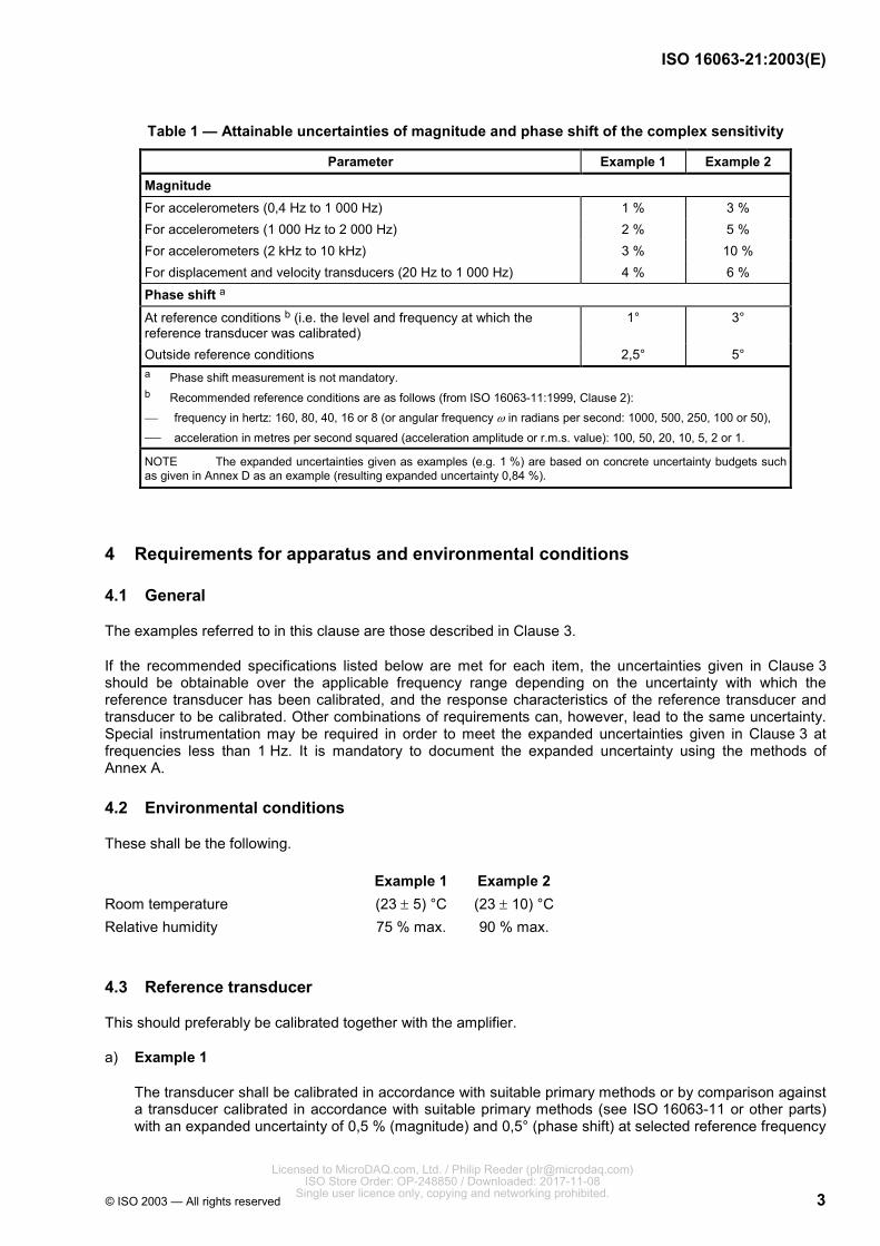
Table 1 — Attainable uncertainties of magnitude and phase shift of the complex sensitivity
Parameter Example 1 Example 2
Magnitude For accelerometers (0,4 Hz to 1 000 Hz) 1 % 3 % For accelerometers (1 000 Hz to 2 000 Hz) 2 % 5 % For accelerometers (2 kHz to 10 kHz) 3 % 10 % For displacement and velocity transducers (20 Hz to 1 000 Hz) 4 % 6 % Phase shift a
At reference conditions b (i.e. the level and frequency at which the reference transducer was calibrated)
1° 3°
Outside reference conditions 2,5° 5° a Phase shift measurement is not mandatory. b Recommended reference conditions are as follows (from ISO 16063-11:1999, Clause 2): frequency in hertz: 160, 80, 40, 16 or 8 (or angular frequency ω in radians per second: 1000, 500, 250, 100 or 50), acceleration in metres per second squared (acceleration amplitude or r.m.s. value): 100, 50, 20, 10, 5, 2 or 1. NOTE The expanded uncertainties given as examples (e.g. 1 %) are based on concrete uncertainty budgets such as given in Annex D as an example (resulting expanded uncertainty 0,84 %).
4 Requirements for apparatus and environmental conditions
4.1 General
The examples referred to in this clause are those described in Clause 3.
If the recommended specifications listed below are met for each item, the uncertainties given in Clause 3 should be obtainable over the applicable frequency range depending on the uncertainty with which the reference transducer has been calibrated, and the response characteristics of the reference transducer and transducer to be calibrated. Other combinations of requirements can, however, lead to the same uncertainty. Special instrumentation may be required in order to meet the expanded uncertainties given in Clause 3 at frequencies less than 1 Hz. It is mandatory to document the expanded uncertainty using the methods of Annex A.
4.2 Environmental conditions
These shall be the following.
Example 1 Example 2 Room temperature (23 ± 5) °C (23 ± 10) °C Relative humidity 75 % max. 90 % max.
4.3 Reference transducer
This should preferably be calibrated together with the amplifier.
a) Example 1
The transducer shall be calibrated in accordance with suitable primary methods or by comparison against a transducer calibrated in accordance with suitable primary methods (see ISO 16063-11 or other parts) with an expanded uncertainty of 0,5 % (magnitude) and 0,5° (phase shift) at selected reference frequency
Licensed to MicroDAQ.com, Ltd. / Philip Reeder ([email protected]) ISO Store Order: OP-248850 / Downloaded: 2017-11-08
Single user licence only, copying and networking prohibited.
ISO 16063-21:2003(E)
4 © ISO 2003 — All rights reserved
and acceleration (the uncertainties are those obtained when calculating expanded uncertainties using a coverage factor of 2). Higher uncertainty values are accepted at high and low frequencies.
b) Example 2
The transducer shall be calibrated by suitable and known methods with traceability to a primary reference transducer and an uncertainty of less than 2 % (magnitude) and 2° (phase shift) at selected reference frequency and acceleration (the uncertainties are those obtained when calculating expanded uncertainties using a coverage factor of 2). Higher uncertainty values are accepted at high and low frequencies.
The reference transducer may be of the so-called back-to-back type meant for direct mounting of the transducer to be calibrated on top of it in a so-called back-to-back configuration (see Figure 1). It may also be a transducer with normal mounting provisions used underneath a fixture in line with the transducer to be calibrated. It is not recommended to mount the two transducers side by side as rocking motions will often be present, causing large errors in many circumstances. For calibrators, the reference transducer may be an integral part of a moving element.
Subclauses 4.4 to 4.8 specify characteristics of apparatus that contribute to the uncertainty of measurement.
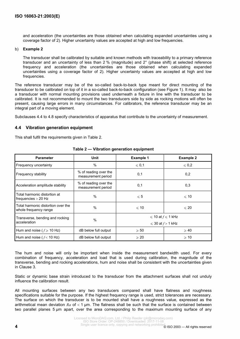
4.4 Vibration generation equipment
This shall fulfil the requirements given in Table 2.
Table 2 — Vibration generation equipment
Parameter Unit Example 1 Example 2
Frequency uncertainty % u 0,1 u 0,2
Frequency stability % of reading over the measurement period 0,1 0,2
Acceleration amplitude stability % of reading over the measurement period 0,1 0,3
Total harmonic distortion at frequencies > 20 Hz % u 5 u 10
Total harmonic distortion over the whole frequency range % u 10 u 20
Transverse, bending and rocking acceleration %
u 10 at f u 1 kHz
u 30 at f > 1 kHz
Hum and noise ( f W 10 Hz) dB below full output W 50 W 40
Hum and noise ( f < 10 Hz) dB below full output W 20 W 10
The hum and noise will only be important when inside the measurement bandwidth used. For every combination of frequency, acceleration and load that is used during calibration, the magnitude of the transverse, bending and rocking accelerations, hum and noise shall be consistent with the uncertainties given in Clause 3.
Static or dynamic base strain introduced to the transducer from the attachment surfaces shall not unduly influence the calibration result.
All mounting surfaces between any two transducers compared shall have flatness and roughness specifications suitable for the purpose. If the highest frequency range is used, strict tolerances are necessary. The surface on which the transducer is to be mounted shall have a roughness value, expressed as the arithmetical mean deviation Ra of < 1 µm. The flatness shall be such that the surface is contained between two parallel planes 5 µm apart, over the area corresponding to the maximum mounting surface of any
Licensed to MicroDAQ.com, Ltd. / Philip Reeder ([email protected]) ISO Store Order: OP-248850 / Downloaded: 2017-11-08
Single user licence only, copying and networking prohibited.
ISO 16063-21:2003(E)
© ISO 2003 — All rights reserved 5
transducer to be calibrated. The drilled and tapped hole for connecting the transducer shall have a perpendicularly tolerance to the surface of < 10 µm, i.e. the centreline of the hole shall be contained in a cylindrical zone with 10 µm diameter and a height equal to the hole depth.
The mounting surface of the vibration exciter should be perpendicular to the direction of motion. Any deviation from perpendicularity should be taken into account in the uncertainty budget, see Annex A.
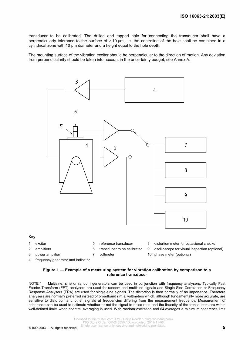
Key
1 exciter 2 amplifiers 3 power amplifier 4 frequency generator and indicator
5 reference transducer 6 transducer to be calibrated 7 voltmeter
8 distortion meter for occasional checks 9 oscilloscope for visual inspection (optional)10 phase meter (optional)
Figure 1 — Example of a measuring system for vibration calibration by comparison to a reference transducer
NOTE 1 Multisine, sine or random generators can be used in conjunction with frequency analysers. Typically Fast Fourier Transform (FFT) analysers are used for random and multisine signals and Single-Sine Correlation or Frequency Response Analysers (FRA) are used for single-sine signals. The distortion is then normally of no importance. Therefore analysers are normally preferred instead of broadband r.m.s. voltmeters which, although fundamentally more accurate, are sensitive to distortion and other signals at frequencies differing from the measurement frequency. Measurement of coherence can be used to estimate whether or not the signal-to-noise ratio and the linearity of the transducers are within well-defined limits when spectral averaging is used. With random excitation and 64 averages a minimum coherence limit
Licensed to MicroDAQ.com, Ltd. / Philip Reeder ([email protected]) ISO Store Order: OP-248850 / Downloaded: 2017-11-08
Single user licence only, copying and networking prohibited.

ISO 16063-21:2003(E)
6 © ISO 2003 — All rights reserved
of 0,98 will ensure that the errors due to signal-to-noise ratio and linearity are less than 0,9 % for a dual channel measurement. In rare cases, broadband excitation can, however, create unwanted (transverse) vibration or output signals at a measuring frequency due to non-linear behaviour of shaker or transducer at other frequencies.
NOTE 2 The items in 4.3 and 4.4 may be integrated into a calibrator.
4.5 Voltage measuring instrumentation
Two alternative set-ups are considered.
a) A single voltmeter measuring true r.m.s. at transducer amplifier output is used. The outputs from the reference transducer and the transducer to be calibrated are measured consecutively and the reference transducer output at least twice. This equipment shall fulfil the requirements given in Table 3.
Table 3 — Voltage measuring instrumentation — Single voltmeter
Parameter Unit Example 1 Example 2
Frequency range Hz 1 to 10 000 1 to 10 000
Maximum deviation from linearity % of reading for max. difference in signal levels 0,1 0,3
Maximum deviation between two consecutive reference transducer measurements
% 0,1 0,3
NOTE The last row describes the repeatability of the measurement. This includes more than the voltmeter repeatability but is treated here as a general requirement.
b) An instrument measuring voltage ratio between transducer amplifier outputs is used. This equipment shall have the characteristics specified in Table 4.
Table 4 — Voltage measuring instrumentations
Parameter Unit Example 1 Example 2
Frequency range Hz 1 to 10 000 1 to 10 000
Maximum uncertainty % 0,2 0,5
4.6 Distortion measuring instrumentation
Distortion measuring instrumentation (limited use, see Note) capable of measuring total harmonic distortion of 1 % to 10 % shall have the characteristics specified in Table 5.
Table 5 — Distortion measuring instrumentation
Parameter Unit Example 1 Example 2
Frequency range Hz 1 to 50 000 1 to 50 000
Maximum uncertainty % of reading 10 10
NOTE Distortion measurement is only needed for sine calibration and is not included in the standard procedure. It is used to check the performance of the vibration generating equipment initially and then only with suitable intervals or in case of doubt.
Licensed to MicroDAQ.com, Ltd. / Philip Reeder ([email protected]) ISO Store Order: OP-248850 / Downloaded: 2017-11-08
Single user licence only, copying and networking prohibited.

ISO 16063-21:2003(E)
© ISO 2003 — All rights reserved 7
4.7 Oscilloscope
An oscilloscope or similar display may be used for examining the waveforms of the transducer signals.
Its use is strongly recommended but not mandatory.
4.8 Phase shift measuring instrumentation
This equipment shall have the characteristics specified in Table 6.
Table 6 — Phase shift measuring
Parameter Unit Example 1 Example 2
Frequency range Hz 1 to 10 000 1 to 10 000
Maximum uncertainty ° (degree) 0,2 0,5
5 Calibration
5.1 Preferred amplitudes and frequencies
Six frequencies, each with associated acceleration (amplitude or r.m.s. value) and equally covering the transducer range, should preferably be chosen from the following series.
a) Acceleration (m/s2):
1, 2, 5, 10 or their multiples of ten.
If broadband signals are used, these values are the total r.m.s. values.
b) Frequency:
selected from standardized one-third-octave frequency series (see ISO 266).
If broadband signals are used, the desired range should be covered in one or more calibrations.
Values chosen should preferably be the same as those used in the reference transducer calibration. If the transducer is to be calibrated at frequencies and accelerations other than those at which the reference has been calibrated, the characteristics of the reference transducer should be assessed at those frequencies and accelerations. The resulting uncertainty component shall be taken into account in the uncertainty budget (see Annex A).
5.2 Measurement requirements
When a calibration is to be performed using a new set-up or a new transducer, it is good practice to carry out the calibration more than once to ensure sufficient repeatability.
It is important to ensure that cable motion and base strain do not appreciably affect the measurement results, particularly at low frequencies. Altering the attachment of the cable, the mounting of the transducer, or both, and noting changes in the measurement results or harmonic distortion may be used to evaluate effects due to these causes. If the measured sensitivity or distortion does not change significantly when compared to the uncertainty in the calibration, then these influences may be neglected. The mounting conditions of the transducer should also be repeatable. This can be verified by remounting the transducer several times and measuring the sensitivity after each successive attachment of the transducer.
If the transducer under test is not being calibrated in combination with an associated signal conditioner or amplifier, then the gain and frequency response (i.e. magnitude and, if needed, phase shift) of the complex
Licensed to MicroDAQ.com, Ltd. / Philip Reeder ([email protected]) ISO Store Order: OP-248850 / Downloaded: 2017-11-08
Single user licence only, copying and networking prohibited.
ISO 16063-21:2003(E)
8 © ISO 2003 — All rights reserved
sensitivity of the signal conditioner or amplifier used with the transducer under test should be determined in a traceable fashion at all measurement frequencies. The sensitivity and frequency response of the reference (transducer plus amplifier) shall also be determined in a traceable fashion at all measurement frequencies.
If any variations, significant compared to the desired uncertainty, are found in the above tests, these should be quantified by making a sufficiently large number of repeated measurements to get a good estimate of the variance. This shall then be included in the final uncertainty statement. This is especially important if the measurement is not made at the frequencies and amplitudes at which the reference transducer was calibrated.
5.3 Calibration procedure
The surfaces of the reference transducer (or fixture) and the transducer to be calibrated shall be examined to verify that they are free from burrs, etc. and that they comply with the manufacturer’s flatness specifications and the specifications of Clause 4.
Mount the reference transducer (see 4.4) and the transducer to be calibrated back-to-back or in-line on a fixture on the exciter or on the exciter with integral working reference transducer using the recommended torque. Below approximately 5 kHz, good fixtures with known characteristics may be used between the transducers. At higher frequencies, the direct back-to-back configuration or integral working reference transducer shall be used. An example of a block diagram of a typical laboratory calibration apparatus is shown in Figure 1. The voltmeter, selector, generator and phase meter are often substituted by a two-channel instrumentation (e.g. dual-channel analyser with internal generator or voltage ratio meter) with sufficient accuracy.
Measure the ratio of the two outputs and the relative phase shift, if needed.
Determine the sensitivity at the reference frequency, for accelerometers preferably at 160 Hz (second choice: 80 Hz), and at the reference acceleration, for accelerometers preferably at 100 m/s2 (other choices: 10 m/s2, 20 m/s2 or 50 m/s2), then determine the sensitivity at other calibration frequencies and accelerations. The results shall be given in absolute terms and/or as a relative deviation (percentage or decibels) and degrees deviation from the sensitivity at the reference point.
In the case of stud-mounted transducers, a thin film of light oil, wax or grease should be used between the mounting surfaces of the transducer(s) and exciter, particularly in the case of calibrations performed at high frequencies (see ISO 5348 for details).
6 Expression of results
If the reference transducer and the transducer under test respond to the same vibration quantity, calculate the magnitude S2 and the phase shift ϕ2 of the complex sensitivity of the transducer to be calibrated using the following formulae:
Magnitude: Phase shift:
22 1
1
XS SX
= 2 2,1 1ϕ ϕ ϕ= +
where
S1, ϕ1 are the magnitude and phase shift of the complex sensitivity of the reference transducer;
X1 is the output from the reference transducer;
X2 is the output from the transducer to be calibrated;
ϕ2,1 is the phase shift between the outputs from the transducer to be calibrated and the reference transducer.
Licensed to MicroDAQ.com, Ltd. / Philip Reeder ([email protected]) ISO Store Order: OP-248850 / Downloaded: 2017-11-08
Single user licence only, copying and networking prohibited.
ISO 16063-21:2003(E)
© ISO 2003 — All rights reserved 9
If the two transducers measure different vibration quantities, calculate the sensitivity of the transducer to be calibrated, using the following formulae.
a) If the magnitude and phase shift of the complex acceleration sensitivity Sa, ϕa were measured:
Magnitude: Phase:
2v aS f S= π 90v aϕ ϕ= − °
2 24s aS f S= π 180s aϕ ϕ= − °
b) If the magnitude and phase shift of the complex velocity sensitivity Sv, ϕv were measured:
Magnitude: Phase:
2s vS f S= π 90s vϕ ϕ= − °
where
Sa, ϕa are the magnitude and phase shift of the complex acceleration sensitivity;
Sv, ϕv are the magnitude and phase shift of the complex velocity sensitivity;
Ss, ϕs are the magnitude and phase shift of the complex displacement sensitivity;
f is the frequency of the vibration, in hertz.
The phase shift is undetermined within modulus 180° until definitions of directions for the transducers, motions and electrical signals are specified (see ISO 16063-1:1998, 3.3, and Annex B for guidance).
For calibrators designed to provide one or more fixed amplitude(s) at one or more frequencies, the sensitivity of the transducer to be calibrated is obtained by using the specified amplitude A and the measured output X in the formula
XSA
=
where A and S must refer to the same vibration quantity.
7 Reporting the calibration results
In addition to the calibration method and instrumentation with calibration due dates, at least the following conditions and characteristics shall be stated when the calibration results are reported.
a) Ambient conditions, Example 1:
temperature of the transducer if measured, or
ambient air temperature and estimated difference from transducer temperature if this is not measured.
b) Ambient conditions, Example 2:
estimated transducer temperature.
Licensed to MicroDAQ.com, Ltd. / Philip Reeder ([email protected]) ISO Store Order: OP-248850 / Downloaded: 2017-11-08
Single user licence only, copying and networking prohibited.
ISO 16063-21:2003(E)
10 © ISO 2003 — All rights reserved
c) Mounting technique:
material of mounting surface,
mounting torque (if stud mounted and optional for Example 2) or adhesive used,
characteristics of mounting components or adapters (if used),
oil or grease or wax (if used),
cable fixing,
orientation (vertical or horizontal).
d) All amplifier settings (if adjustable) when the transducer is calibrated in combination with a signal conditioner or amplifier:
gain,
cut-off frequencies and slope of filters.
e) Calibration results:
values of calibration frequencies and vibration amplitudes,
values of sensitivity (magnitude and phase shift, if measured),
coherence of the measurement if measured,
expanded uncertainty of the calibration (calculated in accordance with Annex A).
f) Coverage factor, if different from k = 2 (corresponding to a confidence level of 95 % for a normal distribution).
Licensed to MicroDAQ.com, Ltd. / Philip Reeder ([email protected]) ISO Store Order: OP-248850 / Downloaded: 2017-11-08
Single user licence only, copying and networking prohibited.
ISO 16063-21:2003(E)
© ISO 2003 — All rights reserved 11
Annex A (normative)
Expression of uncertainty of measurement in calibration
A.1 Calculation of expanded uncertainty of measurement, U
A.1.1 Purpose of U
The uncertainty of measurement in calibration shall be expressed by the "expanded uncertainty" U in accordance with GUM, based on the approach recommended by the International Committee for Weights and Measures (CIPM). The purpose of U is to provide an interval y − U to y + U within which the value of Y, the specific quantity subject to calibration and estimated by y, can be expected to lie with high probability. To confidently assert that y − U u Y u y + U, the expanded uncertainty U shall be determined as follows.
A.1.2 Corrections
Every effort has to be made to identify each effect that significantly influences the measurement result and to compensate for such effects by applying the estimated corrections or correction factors.
If an effect influencing the measurement result is appropriately described by a probability distribution (preferably probability density, see A.1.3) having a significant expected value (in particular for an asymmetrical distribution), the latter shall be treated as systematic error and compensated by correction.
A.1.3 Standard uncertainty estimation
Each component of uncertainty that contributes to the uncertainty of the measurement shall be represented by a standard deviation ui, termed "standard uncertainty", equal to the positive square root of the variance 2.iu
Some standard uncertainties can be obtained as statistically estimated standard deviations by the statistical analysis of series of observations (type A evaluation of standard uncertainty). Other standard uncertainties shall be evaluated as the standard deviation of a probability distribution describing the scientific judgement of all possible values of the respective quantity (type B evaluation of standard uncertainty). The judgement is based on all information available about the quantity. In particular, if there is no specific information about the possible values of a quantity responsible for systematic effects except that these values are within the bounds b− and ,b+ a uniform distribution over the interval [ ; ]b b− + may be used to represent this information. It has a standard uncertainty 3b where ( ) 2b b b+ −= − . The expected value is ( ) 2b b+ −+ to be used for correction in this case.
If an influence quantity can be considered uniformly distributed (rectangular probability density) but is known to be transformed into the measurement result with a specific non-linear function (e.g. sinusoidal; polynomial of second or third order), this information shall be taken into account by choosing the associated distribution model.
EXAMPLE The sensitivity S of an accelerometer to sinusoidal accelerations in the nominal measurement direction is calculated from the output, voltage or charge amplitude ˆ,x stimulated by a vibration, acceleration amplitude ˆ,a using the formula ˆ ˆ/ .S x a= Among the various disturbing effects influencing the measurement result in calibration, there may be a significant transverse motion component from the vibration exciter, acceleration amplitude Tˆ ,a transformed into an error component ˆTxe in the output, in conjunction with the accelerometer's transverse sensitivity, ST. It is assumed for this example that the acceleration to be measured and the transverse acceleration have the same frequency and that there is no phase angle difference. As the transverse sensitivity is usually sinusoidally dependent on the angle β between the direction of maximum transverse sensitivity ( )T,maxS and the direction of a transverse excitation, the error component can be expressed by
ˆT T T T,max T,maxˆ ˆ cosxe S a S a β= =
Licensed to MicroDAQ.com, Ltd. / Philip Reeder ([email protected]) ISO Store Order: OP-248850 / Downloaded: 2017-11-08
Single user licence only, copying and networking prohibited.
ISO 16063-21:2003(E)
12 © ISO 2003 — All rights reserved
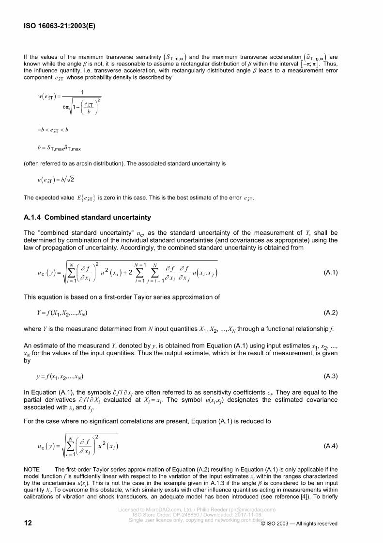
If the values of the maximum transverse sensitivity ( )T,maxS and the maximum transverse acceleration ( )T,maxa are known while the angle β is not, it is reasonable to assume a rectangular distribution of β within the interval ; .−π π Thus, the influence quantity, i.e. transverse acceleration, with rectangularly distributed angle β leads to a measurement error component ˆTxe whose probability density is described by
( )2ˆT
ˆT
ˆT
T,max T,max
1
1
ˆ
xx
x
w eeb
b
b e b
b S a
= π −
− < <
=
(often referred to as arcsin distribution). The associated standard uncertainty is
( )ˆT 2xu e b=
The expected value { }ˆTxE e is zero in this case. This is the best estimate of the error ˆT.xe
A.1.4 Combined standard uncertainty
The "combined standard uncertainty" uc, as the standard uncertainty of the measurement of Y, shall be determined by combination of the individual standard uncertainties (and covariances as appropriate) using the law of propagation of uncertainty. Accordingly, the combined standard uncertainty is obtained from
( ) ( ) ( )2 1
2c
1 1 12 ,
NN N
i i ji i ji i j i
f f fu y u x u x xx x x
∂ ∂ ∂∂ ∂ ∂
=
= = = +
= +
∑ ∑ ∑ (A.1)
This equation is based on a first-order Taylor series approximation of
Y = f (X1, X2,...,XN) (A.2)
where Y is the measurand determined from N input quantities X1, X2, ..., XN through a functional relationship f.
An estimate of the measurand Y, denoted by y, is obtained from Equation (A.1) using input estimates x1, x2, ..., xN for the values of the input quantities. Thus the output estimate, which is the result of measurement, is given by
y = f (x1, x2,...,xN) (A.3)
In Equation (A.1), the symbols ∂ f / ∂ xi are often referred to as sensitivity coefficients ci. They are equal to the partial derivatives ∂ f / ∂ Xi evaluated at Xi = xi. The symbol u(xi,xj) designates the estimated covariance associated with xi and xj.
For the case where no significant correlations are present, Equation (A.1) is reduced to
( ) ( )2
2c
1
N
iii
fu y u xx
∂∂=
=
∑ (A.4)
NOTE The first-order Taylor series approximation of Equation (A.2) resulting in Equation (A.1) is only applicable if the model function f is sufficiently linear with respect to the variation of the input estimates xi within the ranges characterized by the uncertainties u(xi). This is not the case in the example given in A.1.3 if the angle β is considered to be an input quantity Xi. To overcome this obstacle, which similarly exists with other influence quantities acting in measurements within calibrations of vibration and shock transducers, an adequate model has been introduced (see reference [4]). To briefly
Licensed to MicroDAQ.com, Ltd. / Philip Reeder ([email protected]) ISO Store Order: OP-248850 / Downloaded: 2017-11-08
Single user licence only, copying and networking prohibited.

ISO 16063-21:2003(E)
© ISO 2003 — All rights reserved 13
specify this model for the example above, a factor ˆT ˆ(1 / )xe x− with ˆT ˆ/ 1xe x << is introduced, as an input quantity Xi, into the functional relationship used for calculating the measurand. Equation (A.2), specially tailored to the example, is reduced to three input quantities
Y = f (X1, X2, X3)
where
Y is the measurand (sensitivity S);
X1 is the accelerometer output (voltage or charge amplitude ˆ);x
X2 is the acceleration amplitude;
( )ˆ3 T ˆ1 xX e x= − .
Thus, the relationship
13
2
XY XX
=
can be established. The first Taylor series approximation can be used now, leading to the relative combined standard uncertainty
22 2c 1 2 3
1 2 3
( ) ( ) ( ) ( )u y u x u x u xy x x x
= + +
if there are no significant correlations.
Using the symbols introduced in the Example, the latter relationship can be written as follows:
2 2 2ˆc Tˆ ˆ ˆ( ) ( ) ( ) ( / )
ˆ ˆ 1xu S u x u a u e x
S x a
= + +
where
ˆ ˆ( ) /u x x is the relative standard uncertainty of the output voltage amplitude measurement;
ˆ ˆ( )u a a the relative standard uncertainty in acceleration amplitude measurement;
( ) ( )ˆ ˆT Tˆ ˆx xu e x u e x= , with ( )ˆT 2xu e b= as explained in the Example.
Accordingly, further factors whose deviations from the value 1 are similarly expressed by the relative error component of the respective quantity (e.g. voltage, acceleration or the sensitivity as a whole) might be introduced as input quantities (X4, X5, ...), allowing the variety of uncertainty sources to be taken into account separately.
A.1.5 Expanded uncertainty
The "expanded uncertainty" U shall be determined by multiplying uc by a coverage factor k:
U = kuc
where a value of k = 2 should preferably be used. If it can be assumed that the possible values of the calibration result are approximately normally distributed with approximate standard deviation uc, the unknown value can be asserted to lie in the interval defined by U with a level of confidence, or probability, of approximately 95 %.
Licensed to MicroDAQ.com, Ltd. / Philip Reeder ([email protected]) ISO Store Order: OP-248850 / Downloaded: 2017-11-08
Single user licence only, copying and networking prohibited.
ISO 16063-21:2003(E)
14 © ISO 2003 — All rights reserved
A.1.6 Reporting the result
When reporting the result of the measurement y, the expanded uncertainty and the value of the coverage factor k used, if different from k = 2, shall be stated. In addition, the approximate coverage probability or level of confidence of the interval may be stated.
A.2 Calculation of expanded uncertainties at reference conditions
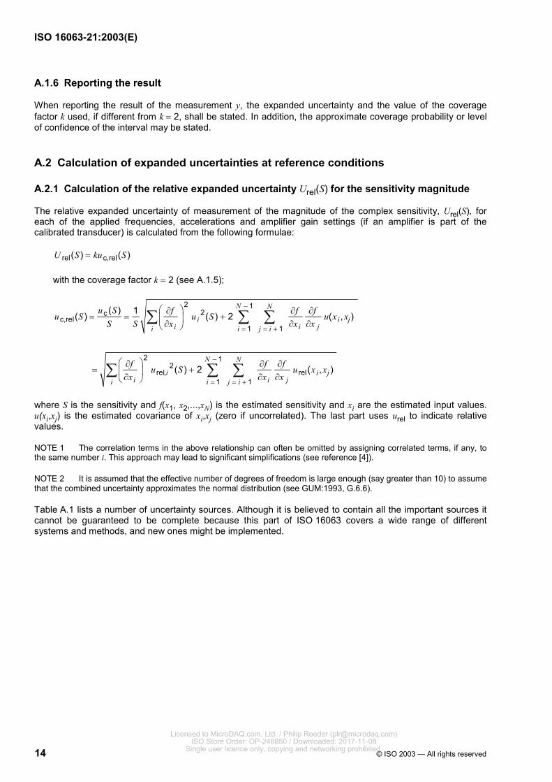
A.2.1 Calculation of the relative expanded uncertainty Urel(S) for the sensitivity magnitude
The relative expanded uncertainty of measurement of the magnitude of the complex sensitivity, Urel(S), for each of the applied frequencies, accelerations and amplifier gain settings (if an amplifier is part of the calibrated transducer) is calculated from the following formulae:
rel c,rel( ) ( )U S ku S=
with the coverage factor k = 2 (see A.1.5);
2 12c
c,rel1 1
2 12
rel, rel1 1
( ) 1( ) ( ) 2 ( , )
( ) 2 ( , )
N N
i i ji i ji i j i
N N
i i ji i ji i j i
u S f f fu S u S u x xS S x x x
f f fu S u x xx x x
−
= = +
−
= = +
∂ ∂ ∂= = + ∂ ∂ ∂
∂ ∂ ∂= +
∂ ∂ ∂
∑ ∑ ∑
∑ ∑ ∑
where S is the sensitivity and f(x1, x2,...,xN) is the estimated sensitivity and xi are the estimated input values. u(xi,xj) is the estimated covariance of xi,xj (zero if uncorrelated). The last part uses urel to indicate relative values.
NOTE 1 The correlation terms in the above relationship can often be omitted by assigning correlated terms, if any, to the same number i. This approach may lead to significant simplifications (see reference [4]).
NOTE 2 It is assumed that the effective number of degrees of freedom is large enough (say greater than 10) to assume that the combined uncertainty approximates the normal distribution (see GUM:1993, G.6.6).
Table A.1 lists a number of uncertainty sources. Although it is believed to contain all the important sources it cannot be guaranteed to be complete because this part of ISO 16063 covers a wide range of different systems and methods, and new ones might be implemented.
Licensed to MicroDAQ.com, Ltd. / Philip Reeder ([email protected]) ISO Store Order: OP-248850 / Downloaded: 2017-11-08
Single user licence only, copying and networking prohibited.

ISO 16063-21:2003(E)
© ISO 2003 — All rights reserved 15
Table A.1 — Uncertainty components for determination of S
i
Standard uncertainty component
u(xi)
Source of uncertainty
Relative uncertainty contribution
urel,i( y )
1 u(S1) The combined standard uncertainty for the reference transducer and amplifier combination at specified conditions
urel,1(S)
2 u(ûR, A) Conditioning amplifier gain urel,2(S)
3 u(ûR) Voltage ratio measurement (often two correlated measurements) urel,3(S)
4 u(ûR, d) Effect of total harmonic distortion on voltage ratio measurement urel,4(S)
5 u(ûR, H) Effect of hum and noise on voltage ratio measurement urel,5(S)
6 u(ûR, v) Effect of transverse, rocking and bending vibration on output voltage ratio urel,6(S)
7 u(ûR, e) Effect of base strain on output voltage ratio urel,7(S)
8 u(ûR, N) Effect of mounting parameters (torque, cable fixing, dummy mass, etc.) on output voltage ratio
urel,8(S)
9 u(ûR, r) Effect of relative motion on output voltage ratio urel,9(S)
10 u(S1, s) Reference stability over time urel,10(S)
11 u(ûR, T) Effect of temperature on output voltage ratio urel,11(S)
12 u( f ) Vibration frequency measurement urel,12(S)
13 u(ûR, L) Effect of non-linearity of transducers on output voltage ratio urel,13(S)
14 u(ûR, I) Effect of non-linearity of amplifiers on output voltage ratio urel,14(S)
15 u(ûR, G) Effect of gravitation on transducers on output voltage ratio urel,15(S)
16 u(ûR, B) Effect of magnetic field from exciter on transducers on output voltage ratio urel,16(S)
17 u(ûR, E) Effect of other environmental parameters on output voltage ratio urel,17(S)
18 u(SRE) Residual effects on sensitivity measurement and on the sensitivity of the transducer to be calibrated (e.g. random effect in repeated measurements; experimental standard deviation of arithmetic mean)
urel,18(S)
NOTE 1 If the method chosen uses a working reference transducer, which at certain intervals is calibrated by the reference transducer then the above calculation needs to be made twice, and the result of the first calculation is used as input to the final calculation. NOTE 2 The sources of uncertainties may be subdivided and numbered in a way differing from that used in this table, provided that each effect significantly influencing the measurement result has been taken into account (see A.1.3).
A.2.2 Calculation of the expanded uncertainty U(∆ϕ) for the phase shift
The expanded uncertainty of measurement of the phase shift ∆ϕ of the complex sensitivity S, at each of the applied frequencies, accelerations and amplifier gain settings (if an amplifier is part of the calibrated transducer) is calculated from the following formulae:
U(∆ϕ) = kuc(∆ϕ)
with the coverage factor k = 2 (see A.1.5);
2 12
c1 1
( ) ( ) 2 ( , )N N
i i ji i ji i j i
g g gu u u x xx x x
ϕ ϕ−
= = +
∂ ∂ ∂∆ = ∆ +
∂ ∂ ∂ ∑ ∑ ∑
Licensed to MicroDAQ.com, Ltd. / Philip Reeder ([email protected]) ISO Store Order: OP-248850 / Downloaded: 2017-11-08
Single user licence only, copying and networking prohibited.

ISO 16063-21:2003(E)
16 © ISO 2003 — All rights reserved
where ∆ϕ is the phase shift of the complex sensitivity and g(x1,x2,...,xN) is the estimated phase shift and xi are the estimated input values; u(xi,xj) is the estimated covariance of xi,xj (zero if uncorrelated).
NOTE 1 The correlation terms in the above relationship can often be omitted by assigning correlated terms, if any, to the same number i. This approach may lead to significant simplifications (see reference [4]).
NOTE 2 It is assumed that the effective number of degrees of freedom is large enough (say greater than 10) to assume that the combined uncertainty approximates the normal distribution (see GUM:1993, G.6.6).
Table A.2 lists a number of uncertainty sources. Although it is believed to contain all the important sources it cannot be guaranteed to be complete because this part of ISO 16063 covers a wide range of different systems and methods, and new ones might be implemented.
Table A.2 — Uncertainty components for determination of ∆ϕ
i
Standard uncertainty component
u(xi) Source of uncertainty
Uncertainty contribution
ui( y )
1 u(∆ϕ1) The combined standard uncertainty on phase shift for the reference transducer and amplifier combination
u1(∆ϕ)
2 u(∆ϕA) Conditioning amplifier phase shift uncertainty u2(∆ϕ)
3 u(ϕ) Phase measurements u3(∆ϕ)
4 u(ϕd) Effect of the total harmonic distortion on the phase measurement u4(∆ϕ)
5 u(ϕH) Effect of hum and noise on the phase measurement u5(∆ϕ)
6 u(ϕT) Effect of transverse, rocking and bending vibration on the output phase u6(∆ϕ)
7 u(ϕe) Effect of base strain on the output phase u7(∆ϕ)
8 u(ϕM) Effect of mounting parameters (torque, cable fixing, dummy mass, etc.) on output phase
u8(∆ϕ)
9 u(ϕR) Effect of relative motion on output phase u9(∆ϕ)
10 u(∆ϕs) Reference transducer phase stability over time u10(∆ϕ)
11 u(ϕT) Effect of temperature on output phase u11(∆ϕ)
12 u(ϕL) Effect of non-linearity of transducers on output phase u12(∆ϕ)
13 u(ϕl) Effect of non-linearity of amplifiers on output phase u13(∆ϕ)
14 u(ϕG) Effect of gravitation on transducers on output phase u14(∆ϕ)
15 u(ϕB) Effect of magnetic field from exciter on transducers on output phase u15(∆ϕ)
16 u(ϕE) Effect of other environmental parameters on output phase u16(∆ϕ)
17 u(∆ϕ1, ∆ϕ2,RE) Residual effects on phase shift measurement and on the output phase of the transducer to be calibrated (e.g. random effect in repeated measurements; experimental standard deviation of arithmetic mean)
u17(∆ϕ)
NOTE 1 If the method chosen uses a working standard transducer, which at certain intervals is calibrated by the reference transducer, then the above calculation needs to be made twice, and the result of the first calculation is used as input to the final calculation. NOTE 2 The sources of uncertainties may be subdivided and numbered in a way differing from that used in this table, provided that each effect significantly influencing the measurement result has been taken into account (see A.1.3).
Licensed to MicroDAQ.com, Ltd. / Philip Reeder ([email protected]) ISO Store Order: OP-248850 / Downloaded: 2017-11-08
Single user licence only, copying and networking prohibited.

ISO 16063-21:2003(E)
© ISO 2003 — All rights reserved 17
A.3 Expanded uncertainties over the complete frequency and amplitude range
A.3.1 Calculation of the relative expanded uncertainty Urel(St) for the magnitude
The relative expanded uncertainty of measurement of the magnitude of the complex sensitivity, Urel(St), calculated in accordance with A.2.1 is only valid for the calibration frequencies, accelerations and amplifier settings (if an amplifier is part of the calibrated transducer). The relative expanded uncertainty of measurement of the magnitude of the complex sensitivity, Urel(St), for the complete frequency and amplitude range, is calculated from the following formulae:
Urel(St) = kuc,rel(St)
with the coverage factor k = 2 (see A.1.5);
2 12c t
c,rel t tt t 1 1
( ) 1( ) ( ) 2 ( , )N N
i i ji i ji i j i
u S f f fu S u S u x xS S x x x
−
= = +
∂ ∂ ∂= = +
∂ ∂ ∂ ∑ ∑ ∑
where
St is the sensitivity determined for the complete frequency and amplitude range;
f(x1,x2,...,xN) is the estimated sensitivity;
xi is the estimated input values;
u(xi,xj) is the estimated covariance of xi,xj (zero if uncorrelated).
NOTE 1 The correlation terms in the above relationship can often be omitted by assigning correlated terms, if any, to the same number i. This approach may lead to significant simplifications (see reference [4]).
NOTE 2 It is assumed that the effective number of degrees of freedom is large enough (say greater than 10) to assume that the combined uncertainty approximates the normal distribution (see GUM:1993, G.6.6).
Table A.3 lists a number of uncertainty sources. Although it is believed to contain all the important sources, it cannot be guaranteed to be complete because this part of ISO 16063 covers a wide range of different systems and methods, and new ones might be implemented.
Licensed to MicroDAQ.com, Ltd. / Philip Reeder ([email protected]) ISO Store Order: OP-248850 / Downloaded: 2017-11-08
Single user licence only, copying and networking prohibited.

ISO 16063-21:2003(E)
18 © ISO 2003 — All rights reserved
Table A.3 — Uncertainty components for determination of St
i
Standard uncertainty component
u(xi) Source of uncertainty
Uncertainty contribution
ui( y )
1 u(S) Uncertainty of the magnitude of the sensitivity calculated at the calibration frequencies, amplitudes and amplifier settings in accordance with A.2.1.
u1(St)
2 u(eT, A) Conditioning amplifier tracking (gain deviations for different amplifications) u2(St)
3 u(eL, f, A) Conditioning amplifier frequency response (gain deviations for different frequencies)
u3(St)
4 u(eL, f, T) Transducer frequency response deviations from theoretical curve (sensitivity deviations from assumed curve at different frequencies)
u4(St)
5 u(eL, a, A) Amplitude effect on amplifier gain u5(St)
6 u(eL, a, T) Amplitude effect on sensitivity (magnitude) of transducer u6(St)
7 u(ei, A) Instability of amplifier gain and effect of source impedance u7(St)
8 u(ei, T) Instability of transducer sensitivity (magnitude) u8(St)
9 u(eE, A) Environmental effects on amplifier gain u9(St)
10 u(eE, T) Environmental effects on transducer sensitivity (magnitude) u10(St)
11 u(eM, T) Additional effects of mounting parameters (torque, cable fixing, dummy mass, etc.) on transducer sensitivity (magnitude)
u11(St)
A.3.2 Calculation of the expanded uncertainty U(∆ϕt) for the phase
The expanded uncertainty of measurement of the phase shift ∆ϕt of the complex sensitivity St, calculated in accordance with A.2.2, is only valid for the calibration frequencies, accelerations and amplifier settings (if an amplifier is part of the calibrated transducer). The expanded uncertainty of measurement of the phase shift of the complex sensitivity, U(St), for the complete frequency and amplitude range is calculated from the following formulae:
U(∆ϕt) = kuc(∆ϕt)
with the coverage factor k = 2 (see A.1.5);
2 12
c t t1 1
( ) ( ) 2 ( , )N N
i i ji i ji i j i
g g gu u u x xx x x
ϕ ϕ−
= = +
∂ ∂ ∂∆ = ∆ +
∂ ∂ ∂ ∑ ∑ ∑
where
∆ϕt is the phase shift of the complex sensitivity determined for the complete frequency and amplitude range;
g(x1,x2,...,xN) is the estimated phase shift;
xi is the estimated input values. u(xi,xj) is the estimated covariance of xi,xj (zero if uncorrelated).
NOTE 1 The correlation terms in the above relationship can often be omitted by assigning correlated terms, if any, to the same number i. This approach may lead to significant simplifications (see reference [4]).
NOTE 2 It is assumed that the effective number of degrees of freedom is large enough (say greater than 10) to assume that the combined uncertainty approximates the normal distribution (see GUM:1993, G.6.6).
Licensed to MicroDAQ.com, Ltd. / Philip Reeder ([email protected]) ISO Store Order: OP-248850 / Downloaded: 2017-11-08
Single user licence only, copying and networking prohibited.
ISO 16063-21:2003(E)
© ISO 2003 — All rights reserved 19
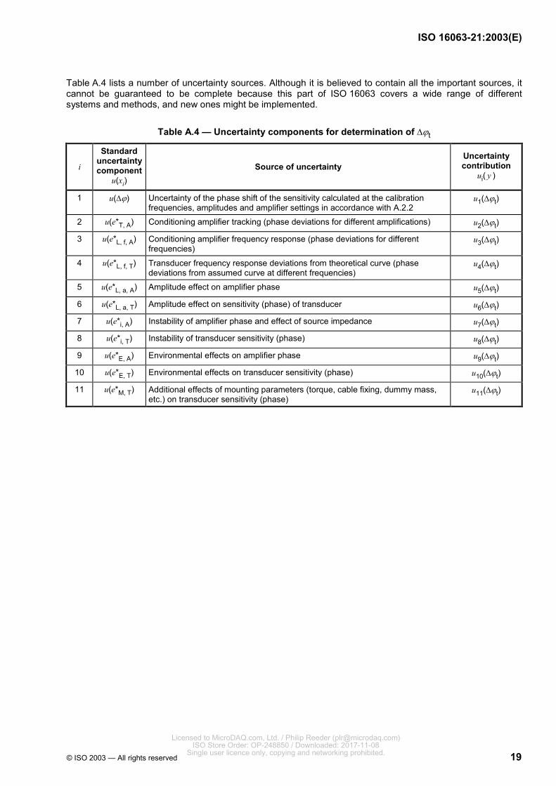
Table A.4 lists a number of uncertainty sources. Although it is believed to contain all the important sources, it cannot be guaranteed to be complete because this part of ISO 16063 covers a wide range of different systems and methods, and new ones might be implemented.
Table A.4 — Uncertainty components for determination of ∆ϕt
i
Standard uncertainty component
u(xi) Source of uncertainty
Uncertainty contribution
ui( y )
1 u(∆ϕ) Uncertainty of the phase shift of the sensitivity calculated at the calibration frequencies, amplitudes and amplifier settings in accordance with A.2.2
u1(∆ϕt)
2 u(e*T, A) Conditioning amplifier tracking (phase deviations for different amplifications) u2(∆ϕt)
3 u(e*L, f, A) Conditioning amplifier frequency response (phase deviations for different frequencies)
u3(∆ϕt)
4 u(e*L, f, T) Transducer frequency response deviations from theoretical curve (phase deviations from assumed curve at different frequencies)
u4(∆ϕt)
5 u(e*L, a, A) Amplitude effect on amplifier phase u5(∆ϕt)
6 u(e*L, a, T) Amplitude effect on sensitivity (phase) of transducer u6(∆ϕt)
7 u(e*i, A) Instability of amplifier phase and effect of source impedance u7(∆ϕt)
8 u(e*i, T) Instability of transducer sensitivity (phase) u8(∆ϕt)
9 u(e*E, A) Environmental effects on amplifier phase u9(∆ϕt)
10 u(e*E, T) Environmental effects on transducer sensitivity (phase) u10(∆ϕt)
11 u(e*M, T) Additional effects of mounting parameters (torque, cable fixing, dummy mass, etc.) on transducer sensitivity (phase)
u11(∆ϕt)
Licensed to MicroDAQ.com, Ltd. / Philip Reeder ([email protected]) ISO Store Order: OP-248850 / Downloaded: 2017-11-08
Single user licence only, copying and networking prohibited.

ISO 16063-21:2003(E)
20 © ISO 2003 — All rights reserved
Annex B (normative)
Definitions of amplitude sign and phase shift between mechanical
motion and vibration transducer electrical output
B.1 Motion
An object has normally 6 degrees of freedom: 3 degrees for linear motion and 3 degrees for rotational motion.
B.2 Coordinate system
All motions are measured in a coordinate system, and for linear motions a Cartesian coordinate system with x, y and z coordinates is recommended.
Angular motion can be measured in the same coordinate system with the addition of a rotation angle. The angular motion is specified in a polar coordinate system with the coordinate axes as rotational axes and the sign for the rotation is defined by using the right-hand grip rule (with the thumb in the direction of the axes, the fingers will point in the positive rotational direction).
B.3 Transducer types
Several different vibration transducer types are available. Accelerometers, velocity transducers, displacement (proximity) probes are typical transducers.
B.4 Units
Amplitudes for vibration signals are specified in either linear or rotational units. The units for the quantities of acceleration, velocity and displacement (length) are metres per second squared, metres per second and metres, respectively, and the unit for phase (angle) is either degrees or radians. The units for the quantities of angular acceleration, angular velocity and angular displacement (plane angle) are radians per second squared, radians per second and radians, respectively, and the unit for rotational phase (angle) is either degrees or radians.
B.5 Definition of coordinate system
The coordinate system is here defined relative to the transducer. One of the axes is parallel to the transducer main axis, and the positive direction is from the measuring surface and through the transducer.
B.6 Definition of polarity or sign for motion
A linear motion (acceleration, velocity or displacement) has a positive sign when the motion is in the positive direction of the axis parallel to the transducer main axis.
A rotational or angular motion has a positive sign when the motion is in the same direction as the positive angle.
This definition is independent of the mounting of the transducer (contact or non-contact transducer).
Licensed to MicroDAQ.com, Ltd. / Philip Reeder ([email protected]) ISO Store Order: OP-248850 / Downloaded: 2017-11-08
Single user licence only, copying and networking prohibited.

ISO 16063-21:2003(E)
© ISO 2003 — All rights reserved 21
B.7 Definition of sensitivity (magnitude and phase shift) for transducers
The transducer converts the physical parameter to another parameter, usually an electrical output signal. The output signal could either be a voltage, current or charge value.
The sensitivity is defined as the ratio between the electrical output and a specified motion. The sensitivity includes a value with sign and a phase shift specification based on the previous definition of coordinate system, motion and the conversion in the transducer.
Licensed to MicroDAQ.com, Ltd. / Philip Reeder ([email protected]) ISO Store Order: OP-248850 / Downloaded: 2017-11-08
Single user licence only, copying and networking prohibited.
ISO 16063-21:2003(E)
22 © ISO 2003 — All rights reserved
Annex C (informative)
Nomogram for conversion between acceleration, velocity and
displacement
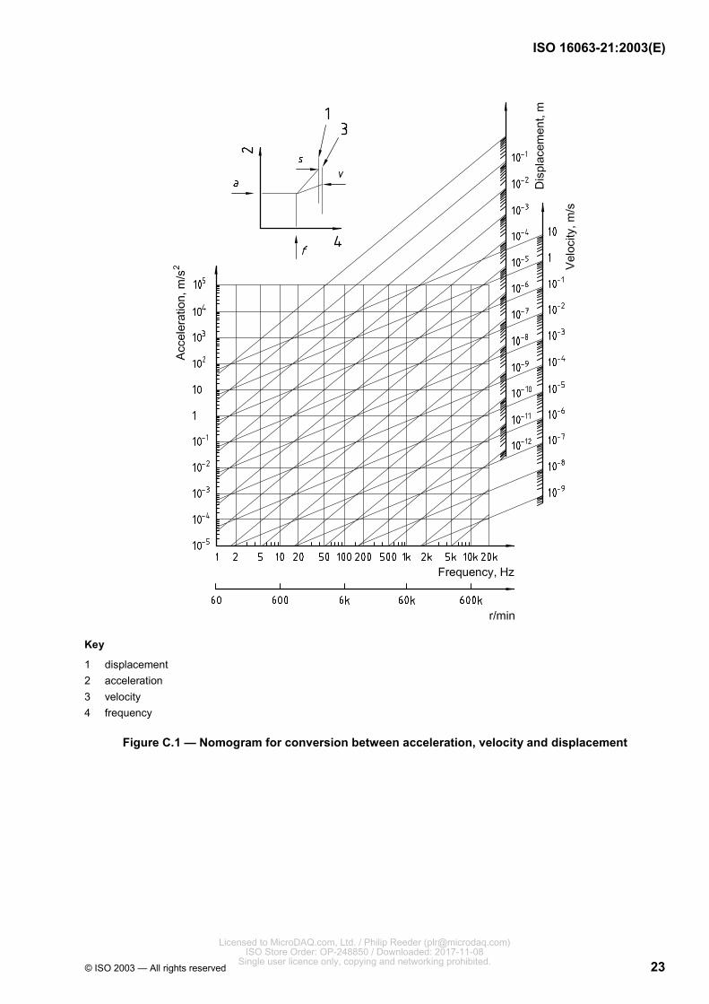
Figure C.1 shows a nomogram for conversion between acceleration, velocity and displacement of vibration magnitude(s) (r.m.s. or peak or peak-to-peak values) at discrete frequencies. If different parameters are used, the factor 2 (r.m.s. to peak) or 2 2 (r.m.s. to peak-to-peak) should be used. With two known parameters, the other two can be found.
For example, if the frequency and acceleration level are known, use the nomogram shown to read the corresponding velocity and displacement magnitude(s) off the respective scales.
Licensed to MicroDAQ.com, Ltd. / Philip Reeder ([email protected]) ISO Store Order: OP-248850 / Downloaded: 2017-11-08
Single user licence only, copying and networking prohibited.
ISO 16063-21:2003(E)
© ISO 2003 — All rights reserved 23
Key
1 displacement 2 acceleration 3 velocity 4 frequency
Figure C.1 — Nomogram for conversion between acceleration, velocity and displacement
Licensed to MicroDAQ.com, Ltd. / Philip Reeder ([email protected]) ISO Store Order: OP-248850 / Downloaded: 2017-11-08
Single user licence only, copying and networking prohibited.

ISO 16063-21:2003(E)
24 © ISO 2003 — All rights reserved
Annex D (informative)
Example of uncertainty calculation
D.1 General
To facilitate the use of the previously given principles, an example based on a set-up as shown in Figure 1 is given in this annex.
The measurement process may be represented as shown in Figure D.1.
Key
1 mechanical vibrator 2 reference accelerometer set 3 voltmeter 4 transducer to be calibrated 5 amplifier
Figure D.1 — Scheme of the measurement process
D.2 Symbols
The following symbols are used in this annex:
a Acceleration in main direction
av Acceleration transverse to main direction
ad Acceleration distortion in main direction
S1 Sensitivity magnitude of reference transducer set
u1 Voltage at output of reference transducer set
V1 Voltmeter reading (reference voltages and accelerations are r.m.s. values)
S2 Sensitivity magnitude of transducer to be calibrated
Licensed to MicroDAQ.com, Ltd. / Philip Reeder ([email protected]) ISO Store Order: OP-248850 / Downloaded: 2017-11-08
Single user licence only, copying and networking prohibited.
ISO 16063-21:2003(E)
© ISO 2003 — All rights reserved 25
SA Sensitivity magnitude of conditioning amplifier
u2 Voltage at amplifier output (transducer to be calibrated)
V2 Voltmeter reading of transducer to be calibrated
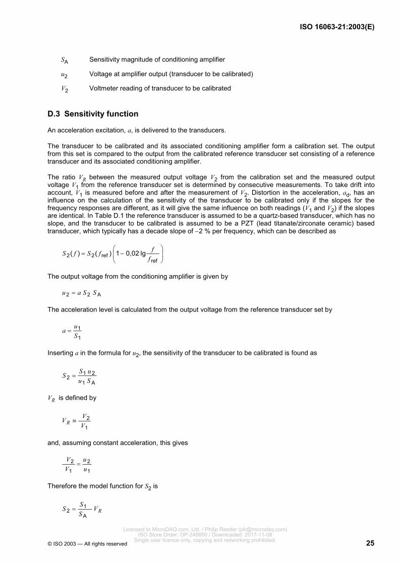
D.3 Sensitivity function
An acceleration excitation, a, is delivered to the transducers.
The transducer to be calibrated and its associated conditioning amplifier form a calibration set. The output from this set is compared to the output from the calibrated reference transducer set consisting of a reference transducer and its associated conditioning amplifier.
The ratio VR between the measured output voltage V2 from the calibration set and the measured output voltage V1 from the reference transducer set is determined by consecutive measurements. To take drift into account, V1 is measured before and after the measurement of V2. Distortion in the acceleration, ad, has an influence on the calculation of the sensitivity of the transducer to be calibrated only if the slopes for the frequency responses are different, as it will give the same influence on both readings (V1 and V2) if the slopes are identical. In Table D.1 the reference transducer is assumed to be a quartz-based transducer, which has no slope, and the transducer to be calibrated is assumed to be a PZT (lead titanate/zirconate ceramic) based transducer, which typically has a decade slope of −2 % per frequency, which can be described as
2 2 refref
( ) ( ) 1 0,02 lg fS f S ff
= −
The output voltage from the conditioning amplifier is given by
2 2 Au a S S=
The acceleration level is calculated from the output voltage from the reference transducer set by
1
1
uaS
=
Inserting a in the formula for u2, the sensitivity of the transducer to be calibrated is found as
1 22
1 A
S uSu S
=
VR is defined by
2
1R
VVV
≡
and, assuming constant acceleration, this gives
2 2
1 1
V uV u
=
Therefore the model function for S2 is
12
AR
SS VS
=
Licensed to MicroDAQ.com, Ltd. / Philip Reeder ([email protected]) ISO Store Order: OP-248850 / Downloaded: 2017-11-08
Single user licence only, copying and networking prohibited.

ISO 16063-21:2003(E)
26 © ISO 2003 — All rights reserved
D.4 Calculation of uncertainty
Following reference [4], the influence from quantities not directly included in the above model function is expanded to
12 1
A...R M
SS V I IS
= × × ×
where the factors I1 to IM describe the errors due to influence quantities.
The mean value equals 1 (and with different distributions, normal, rectangular, etc.) and is given as
2,
1,
11
ii
i
eI
e−
=−
where ei denotes the ith error component due to an influence quantity characterized by an appropriate distribution model. The error component ei can, only under certain conditions, be estimated by a simple distribution model such as rectangular distribution and mean value equal to 0.
Each influence factor contains the influence from one quantity on VR from both V1 and V2.
For each influence factor, Ii, the possible correlation between errors is taken into account. Preferably the influence factors are chosen so that correlated influences are contained in one factor rendering all influence factors uncorrelated.
Under the assumption that the errors ei are small, the second (and higher) order terms in the Taylor series may be neglected.
According to reference [4], the correlation coefficient may be assumed to be zero if there is no indication of a strong correlation.
If the correlation factor between the influences on VR is unknown, the influences are treated in accordance with Equation D.10 in reference [3]:
( ) ( ) ( ) ( )2 2 21 2( ) ru y u y u y u y+ +u
where u1(y) and u2(y) are the uncertainties for the correlated elements (standard deviation for approximated normal distributions), and ur(y) is the combined uncertainty for the uncorrelated elements.
The budget of uncertainty is based upon calculation of relative uncertainties. For uncorrelated elements, the relative combined uncertainty (k = 1) for S2, uc,rel (S2) is given by:
22rel,2 c 2
c,rel 2 22 1
( )( )N
i i
ii
u cu Su SxS =
= =
∑
where ci are the sensitivity coefficients, which are found as the partial derivatives of the model function with respect to the different quantities. As the model function only contains factors in the nominator and one denominator, all becomes 1 or −1, which means they are basically without any importance as all are squared.
An example with numbers is given in Table D.1. The expanded relative uncertainty (coverage factor k = 2) is:
95 2rel, 95 2
2
( )( ) 0,84 %U SU S
S= =
Licensed to MicroDAQ.com, Ltd. / Philip Reeder ([email protected]) ISO Store Order: OP-248850 / Downloaded: 2017-11-08
Single user licence only, copying and networking prohibited.

ISO 16063-21:2003(E)
© ISO 2003 — All rights reserved 27
The expanded uncertainty calculated with the coverage factor k = 2 corresponds to the confidence limit for the coverage probability P = 95 % (assuming normal distribution).
Table D.1 — Example of budget of uncertainty for a piezoelectric accelerometer at 160 Hz and 100 m/s2s
Quantity Description
Relative expanded uncertainty or bounds
of estimated error components
%
Probability distribution
model
Factor
xi
Sensitivity coefficient
ci
Relative contribution
urel,i ( y )
%
S1 Calibration of reference transducer set 0,5 Normal (k = 2) 1/ 2 1 0,25
S1, s Drift for 3 years, manufacturer specification < 0,05 % per year 0,15 Rectangular 1/ 3 1 0,087
SA,Cal Sensitivity of conditioning amplifier calibration, specification 0,25 Rectangular 1/ 3 −1 0,14
VR Voltage ratio, specification 0,2 Rectangular 1/ 3 1 0,12
I(VR,T)
Influence on VR: measurement from temperature variation. Reference transducer sensitivity, (23 ± 3) °C, < 0,02 % per °C
Transducer to be calibrated, (23 ± 3) °C, < 0,1 % per °C
0,36 Rectangular 1/ 3 1 0,21
I(VR, s) Maximum allowed difference between the reference level before and after the measurement, 0,2 %
0,2 Rectangular 1/ 3 1 0,12
I(VR, N) Influence of mounting parameters on transducer to be calibrated, cable, plug and torque, maximum 0,05 %
0,05 Rectangular 1/ 3 1 0,029
I(VR, d)
Influence on VR: measurement from acceleration distortion
Difference in frequency slopes between transducer to be calibrated (PZT) and reference transducer (quartz) typically −2 % per decade of frequency
Dominating 3rd harmonic less than 5 %. Assuming rectangular distribution
0,002 4
See Note 2 Rectangular 1/ 3 1 0,0014
I(VR, v)
Influence on VR measurement from transverse acceleration
Transverse vibration aT for vibrator maximum 10 %
Transverse sensitivity, reference transducer, Sv,1, max. 2 %
Transverse sensitivity, transducer to be calibrated, Sv,2, max. 5 %
2 2 2, 2 , 1 T( )v vS S a+ = 0,51
See Note 3 and refs. [4] and [5] for explanation of
the formula
Special
118
See Note 3 and
refs. [4] and [5] for
explanation of the factor
1/18
1 0,12
I(VR, e) Influence on VR measurement from base strain. Estimated to be less than 0,05 Rectangular 1/ 3 1 0,029
Licensed to MicroDAQ.com, Ltd. / Philip Reeder ([email protected]) ISO Store Order: OP-248850 / Downloaded: 2017-11-08
Single user licence only, copying and networking prohibited.
ISO 16063-21:2003(E)
28 © ISO 2003 — All rights reserved
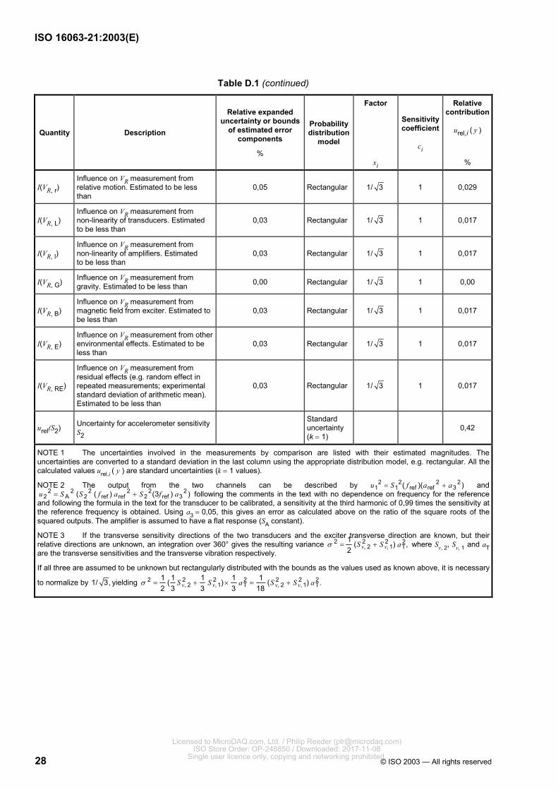
Table D.1 (continued)
Quantity Description
Relative expanded uncertainty or bounds
of estimated error components
%
Probability distribution
model
Factor
xi
Sensitivity coefficient
ci
Relative contribution
urel,i ( y )
%
I(VR, r) Influence on VR measurement from relative motion. Estimated to be less than
0,05 Rectangular 1/ 3 1 0,029
I(VR, L) Influence on VR measurement from non-linearity of transducers. Estimated to be less than
0,03 Rectangular 1/ 3 1 0,017
I(VR, l) Influence on VR measurement from non-linearity of amplifiers. Estimated to be less than
0,03 Rectangular 1/ 3 1 0,017
I(VR, G) Influence on VR measurement from gravity. Estimated to be less than 0,00 Rectangular 1/ 3 1 0,00
I(VR, B) Influence on VR measurement from magnetic field from exciter. Estimated to be less than
0,03 Rectangular 1/ 3 1 0,017
I(VR, E) Influence on VR measurement from other environmental effects. Estimated to be less than
0,03 Rectangular 1/ 3 1 0,017
I(VR, RE)
Influence on VR measurement from residual effects (e.g. random effect in repeated measurements; experimental standard deviation of arithmetic mean). Estimated to be less than
0,03 Rectangular 1/ 3 1 0,017
urel(S2) Uncertainty for accelerometer sensitivity S2
Standard uncertainty (k = 1)
0,42
NOTE 1 The uncertainties involved in the measurements by comparison are listed with their estimated magnitudes. The uncertainties are converted to a standard deviation in the last column using the appropriate distribution model, e.g. rectangular. All the calculated values urel,i ( y ) are standard uncertainties (k = 1 values).
NOTE 2 The output from the two channels can be described by 2 2 2 21 1 ref ref 3( )( )u S f a a= + and
2 2 2 2 2 22 A 2 ref ref 2 ref 3( ( ) (3 ) )u S S f a S f a= + following the comments in the text with no dependence on frequency for the reference
and following the formula in the text for the transducer to be calibrated, a sensitivity at the third harmonic of 0,99 times the sensitivity at the reference frequency is obtained. Using a3 = 0,05, this gives an error as calculated above on the ratio of the square roots of the squared outputs. The amplifier is assumed to have a flat response (SA constant).
NOTE 3 If the transverse sensitivity directions of the two transducers and the exciter transverse direction are known, but their relative directions are unknown, an integration over 360° gives the resulting variance 2 2 2 2
, 2 , 1 T1 ( ) ,2 v vS S aσ = + where Sv, 2, Sv, 1 and aT
are the transverse sensitivities and the transverse vibration respectively.
If all three are assumed to be unknown but rectangularly distributed with the bounds as the values used as known above, it is necessary
to normalize by 1/ 3, yielding 2 2 2 2 2 2 2, 2 , 1 T , 2 , 1 T
1 1 1 1 1( ) ( ) .2 3 3 3 18v v v vS S a S S aσ = + × = +
Licensed to MicroDAQ.com, Ltd. / Philip Reeder ([email protected]) ISO Store Order: OP-248850 / Downloaded: 2017-11-08
Single user licence only, copying and networking prohibited.

ISO 16063-21:2003(E)
© ISO 2003 — All rights reserved 29
Bibliography
[1] ISO 5348, Mechanical vibration and shock — Mechanical mounting of accelerometers
[2] International vocabulary of basic and general terms in metrology (VIM). BIPM, IEC, IFCC, ISO, IUPAC, IUPAP, OIML, 1993
[3] Expression of the uncertainty of measurement in calibration. Publication Reference EA - 4/02, European Co-operation for Accreditation, 1999
[4] MARTENS, H.-J. von and ROGAZEWSKI, P. Representation and transfer of the units of vibration quantities in the GDR. Bulletin OIML, No. 108, 1987, pp. 26-37
[5] MARTENS, H.-J. von. Evaluation of interferometric vibration measurements, SPIE, 4072, 2000, pp. 82-101
Licensed to MicroDAQ.com, Ltd. / Philip Reeder ([email protected]) ISO Store Order: OP-248850 / Downloaded: 2017-11-08
Single user licence only, copying and networking prohibited.

ISO 16063-21:2003(E)
ICS 17.160 Price based on 29 pages
© ISO 2003 — All rights reserved
Licensed to MicroDAQ.com, Ltd. / Philip Reeder ([email protected]) ISO Store Order: OP-248850 / Downloaded: 2017-11-08
Single user licence only, copying and networking prohibited.