international scientific-technical and production journal · schematic diagram of sampling for...
TRANSCRIPT

CONTENTS
SCIENTIFIC AND TECHNICAL
Grigorenko G.M., Golovko V.V., Kostin V.A. and GrabinV.F. Effect of microstructural factors on sensitivity of weldswith ultra-low carbon content to brittle fracture ..................................... 2
Maksimov S.Yu. Evaluation of the influence of wetunderwater welding conditions on the probability of poreformation in the weld metal ................................................................. 10
Kuzmenko V.G. and Guzej V.I. Pore formation in weld metalin submerged arc welding with surface saturation of grainswith fluorine ........................................................................................ 14
Shonin V.A., Gushcha O.I., Mashin V.S., Kovalchuk V.S.and Kuzmenko A.Z. Influence of the dimensions of aspecimen of aluminium alloy welded joint on the residualstressed state and fatigue resistance .................................................. 18
Ulshin V.A. and Kharlamov M.Yu. Optimization ofparameters of detonation-gas spraying using a geneticalgorithm ............................................................................................ 29
INDUSTRIAL
Blashchuk V.E. and Shelenkov G.M. Fusion welding oftitanium and its alloys (Review) ............................................................ 35
Shelyagin V.D., Khaskin V.Yu. and Lukashenko A.G.CO2-laser cutting of disk saw bodies ................................................... 43
Vornovitsky I.N., Zakharova N.V., Shishkova O.V., VilisovA.A. and Zinchenko A.V. Technological peculiarities ofhigh-alloy steel welding by electrodes with rutile coating ...................... 46
Illarionov S.Yu., Dobrushin L.D., Polyakov S.G. andBoeva G.E. Increase of corrosion resistance of welded jointsof high-strength aluminium alloys by explosion cladding ...................... 48
Zhadkevich A.M. Sources of beam heating for brazing(Review) ............................................................................................. 51
BRIEF INFORMATION
Kiselevsky F.N., Dolinenko V.V. and Topchev D.D. Methodof software development using control graphs and languagesmeans ISaGRAF for intelligent welding controllers ................................ 58
Theses for scientific degrees .............................................................. 60
© PWI, In ternat ional Associa t ion «Welding», 2005
English translation of the monthly «Avtomaticheskaya Svarka» (Automatic Welding) journal published in Russian since 1948
International Scientific-Technical and Production Journal
Founders: E.O. Paton Electric Welding Institute of the NAS of Ukraine Publisher: International Association «Welding» International Association «Welding»
Editor-in-Chief B.E.Paton
Editorial board:Yu.S.Borisov V.F.Grabin
Yu.Ya.Gretskii A.Ya.IshchenkoB.V.Khitrovskaya V.F.Khorunov
I.V.KrivtsunS.I.Kuchuk-Yatsenko
Yu.N.Lankin V.K.LebedevV.N.Lipodaev L.M.Lobanov
V.I.Makhnenko A.A.MazurV.F.Moshkin O.K.Nazarenko
I.K.Pokhodnya I.A.RyabtsevYu.A.Sterenbogen N.M.VoropaiK.A.Yushchenko V.N.Zamkov
A.T.Zelnichenko
International editorial council:N.P.Alyoshin (Russia)B.Braithwaite (UK)
C.Boucher (France)Guan Qiao (China)
U.Diltey (Germany)P.Seyffarth (Germany)
A.S.Zubchenko (Russia)T.Eagar (USA)K.Inoue (Japan)
N.I.Nikiforov (Russia)B.E.Paton (Ukraine)
Ya.Pilarczyk (Poland)D. von Hofe (Germany)
Zhang Yanmin (China)V.K.Sheleg (Belarus)
Promotion group:V.N.Lipodaev, V.I.Lokteva
A.T.Zelnichenko (exec. director)Translators:
A.V.Gorskaya, I.N.Kutianova,T.K.Vasilenko
EditorN.A.Dmitrieva
Electron galley:I.S.Batasheva, T.Yu.Snegiryova
Address:E.O. Paton Electric Welding Institute,International Association «Welding»,
11, Bozhenko str., 03680, Kyiv, UkraineTel.: (38044) 287 67 57Fax: (38044) 528 04 86
E-mail: [email protected]://www.nas.gov.ua/pwj
State Registration CertificateKV 4790 of 09.01.2001
Subscriptions:12 issues per year;
460$ ---- regular, 390$ ---- for subscriptionagencies, 260$ ---- for students;postage and packaging included.
Back issues available.
All rights reserved.This publication and each of the articles
contained herein are protected by copyright.Permission to reproduce material contained inthis journal must be obtained in writing from
the Publisher.Copies of individual articles may be obtained
from the Publisher.
February2005
# 2

EFFECT OF MICROSTRUCTURAL FACTORSON SENSITIVITY OF WELDS WITH ULTRA-LOW
CARBON CONTENT TO BRITTLE FRACTURE
G.M. GRIGORENKO, V.V. GOLOVKO, V.A. KOSTIN and V.F. GRABINE.O. Paton Electric Welding Institute, NASU, Kiev, Ukraine
Morphological features of microstructure of weld metal with ultra-low carbon content have been studied. It is shownthat in such welds both MAC-phase and lamellar forms of ferrite are the structural factors that cause instability ofproperties. It has been found that the content of the MAC-phase should not exceed 5--6 vol.% at a low content of ferritewith an ordered secondary phase to provide consistently high properties at low temperatures. It is shown that impacttoughness of the welds studied rises with increase in the content of the ductile component in fracture.
K e y w o r d s : arc welding, low-alloy steels, weld metal, ul-tra-low content of carbon, structure, acicular ferrite, MAC-phase, ferrite with ordered and disordered secondary phase,structural components, quasi-cleavage, impact toughness
Optimal strength and ductile properties of metal ofthe welds in low-alloy steels are achieved primarilyowing to a favourable combination of a set of ferrite-cementite structures. The following structural com-ponents are formed in such a weld metal: acicularferrite (AF), polygonal (allotriomorphic) ferrite(PF), Widmanstatten ferrire (WF), ferrite with or-dered (OSP) and disordered secondary phase (DSP),as well as martensite-austenite-carbide phase (MAC-phase) formed during the austenite dissociation proc-ess.
It is reported [1, 2] that, among all the abovestructural components, AF has the best properties interms of resistance to brittle fracture, which is causedby its morphological peculiarities: AF is formedmainly inside primary crystalline grains, its needlesare 2--8 µm long and 1--2 µm thick, and the ratio oftheir sides is 1:3 to 1:10, high-angle boundaries witha disorientation angle of more than 20° are formedbetween the needles, micro-phases, i.e. carbides orMAC-phase, are formed at the interface between theferrite grains, and dislocations inside the AF grainshave high density (ρ = 1⋅1012 cm--2).
At the same time, analysis of literature data showsthat there are cases where it is impossible to achievehigh cold resistance of the weld metal, despite thepresence of AF in it [3, 4]. It can be seen from thedata shown in Figure 1 that impact toughness some-what decreases at a content of AF in the weld metalequal to more than 70 vol.%. Given that these resultswere obtained for welds with a carbon content of0.12--0.15 wt.%, it can be suggested that this effectis caused by contribution of an unaccounted structuralfactor, e.g. MAC-phase.
Study [4] explains decrease in impact toughnessof the weld metal with a high content of alloyingelements by growth of its tensile strength without acorresponding decrease in grain size. However, thereis a different opinion, according to which decrease inimpact toughness is related to the fact that the weldmetal contains micro-phases that act, similar to oxideinclusions, as brittle crack initiation centres [5, 6].
The purpose of this study was to investigate theeffect of structural components of the weld metal onits sensitivity to brittle fracture at low temperatures,and to reveal factors that lead to decrease in propertiesof the weld metal containing AF.
Experimental procedure. The studies were con-ducted on specimens of metal of the welds with anexperimentally found decrease in impact toughness atnegative temperatures at a content of AF in theirstructure equal to more than 70 vol.%. These weldswere made by butt welding with V-groove preparation(included angle 60°) on 32 mm thick steel 10KhSND© G.M. GRIGORENKO, V.V. GOLOVKO, V.A. KOSTIN and V.F. GRABIN, 2005
Figure 1. Effect of volume content of AF on impact toughnessKCV according to experimental data given in [3] (a) and [4] (b)
2 2/2005

(wt.%: 0.12C, 0.5--0.8Mn, 0.8--1.1Si, 0.6--0.9Cr, 0.5--0.8Ni, 0.4--0.65Cu) using neutral flux ANK-57 (DIN32 522, BFB 155, DC 8, KMHP 5) and four weldingwires Sv-03G2N2MTA, Sv-03G2N2TA, Sv-04N3GMTA and Sv-06G2NMTA (TU 14-143-508--99). The choice of the types of welding wire was basedon the task to provide welds with a different contentof carbon, nickel and molybdenum. Welding was per-formed at a direct current of reversed polarity underthe following conditions: Iw = (620 ± 5) A, Ua == (30 ± 1) V, vw = (20 ± 5) m/h, and qw ≅≅ 48 kJ/cm. The rate of cooling of a weld was 4--7 °C/s in a temperature range of 800--500 °C.
Chemical composition of metal of the last pass ofthe weld was determined by spectral analysis usingthe Baird unit equipped with IBM PC. From threeto five measurements were made for each specimen,and the results thus obtained were averaged. The re-sults of analysis of chemical composition of the weldmetals and welding wires are given in Table 1.
Specimens for evaluation of mechanical propertiesof the deposited metal were made from metal of thewelds studied (Figure 2).
Quantitative determination of microstructuralcomponents was done in accordance with the IIWprocedure [7]. The content of alloying elements insolid solution and composition of non-metallic inclu-sions were determined by the method of X-ray spectralmicroanalysis using the Link System energy-disper-sive spectrometer Link 860/500 and wave-dispersivespectrometer Ortec. Microstructure of metal of thewelds studied is shown in Figure 3.
Investigation results. As found as a result of met-allographic examinations, all specimens of the depos-ited metal were characterised by the presence of such
components as AF, PF and MAC-phase. In addition,a small amount of lamellar forms of ferrite was re-vealed. According to the IIW classifications, theseforms are OSP and DSP. They have to be taken intoaccount, as this type of structure may have a markedeffect on sensitivity of the weld metal to brittle frac-ture. Data on the content of structural componentsin the specimens studied are given in Table 2.
The weight content of elements in AF and PF wasdetermined by the method of quantitative microana-lysis using scanning electron microscope JSM-840 andsoftware ZAF4/FLS for analysis of flat surfaces onetched specimens. The content of alloying elementsin the MAC-phase and on the fracture surface wasdetermined using software ZAF/PB intended foranalysis of particles and rough surfaces (fractures).The results obtained are given in Table 3. As shownby the studies, compared with PF, AF is richer in
Figure 2. Schematic diagram of sampling for metallographic ex-amination and evaluation of mechanical properties of depositedmetal of the welds: 1, 4 ---- sections for metallographic examina-tions; 2, 3 ---- specimens for evaluation of impact toughness andstrength, respectively
Table 1. Chemical composition (wt.%) of weld metal and welding wire for the specimens studied
Wire grade,weld No.
Ñ Al Si Ti Ni Mn Mo Cr Cu S P
Sv-03G2N2MTA, 0.030 0.003 0.140 0.004 2.63 1.16 0.60 0.27 0.15 0.011 0.011
1 0.058 0.013 0.330 0.006 1.72 0.92 0.44 0.32 0.30 0.010 0.011
Sv-03G2N2TA, 0.030 0.002 0.160 0.004 2.58 1.65 0.17 0.28 0.15 0.011 0.010
2 0.045 0.010 0.340 0.005 1.71 0.69 0.23 0.30 0.30 0.010 0.012
Sv-04N3GMTA, 0.036 0.002 0.235 0.018 2.53 1.01 0.26 0.10 0.16 0.014 0.007
3 0.048 0.012 0.460 0.008 1.87 0.99 0.30 0.24 0.30 0.014 0.009
Sv-06G2NMTA, 0.060 0.002 0.200 0.008 1.20 1.40 0.52 0.26 0.16 0.011 0.016
4 0.073 0.013 0.420 0.013 1.27 1.28 0.27 0.28 0.40 0.010 0.016
Table 2. Content (vol.%) of main structural components in weldmetal
WeldNo.
PF AF OSPF DSPF MAC-phase
1 13.7 61.1 1.5 18.5 5.15
2 29.4 51.0 2.5 11.5 5.00
3 19.4 70.5 2.6 2.5 6.97
4 15.8 73.4 4.5 3.5 6.42
2/2005 3

nickel and molybdenum, while the MAC-phase hasthe highest content of these elements.
Fractography of the fracture surface (Figure 4)shows that fracture occurs by the same mechanism inall the specimens. Regions of quasi-cleavage (toughcleavage), which are small brittle fracture facets 2--5 µm in size separated by high-angle boundaries, aswell as regions of tough pitting fracture can be seenon the fracture surfaces. Extended branching linescalled combs are a characteristic element of the frac-ture surfaces of the welds studied. The metal of weld1 is characterised by a uniform distribution of thequasi-cleavage facets, the size of which is comparablewith size of the ferrite needles (1--6 µm). The studiesshow that welds 2--4 have extended cleavage regions10--20 µm wide and 50--100 µm long, elongated in thesame direction.
To determine structural components in which thefracture occurs, it is necessary to investigate compo-sition of metal of the characteristic fracture regionsof the welds and compare them with that of the struc-tural components given in Table 3. The regions ofquasi-cleavage, tough pitting fracture and fracturesurface of the type of the combs, i.e. the region ofplastic deformation, were selected for analysis.
The results of microanalysis of the characteristicregions of fracture of the weld metal are given inTable 4.
Fracture was found to occur in certain structuralcomponents. Comparison of the results of analysis ofchemical composition of metal of the fracture surfacesgiven in Tables 3 and 4, as well as characteristic sizesand morphology of fracture (quasi-cleavage, pitting,combs) and structure elements (AF, PF, MAC-phase),
Figure 3. Microstructure of metal of the welds (a--d correspond to welds Nos. 1--4 in Table 2) (×500)
Table 3. Content of alloying elements (wt.%) in structural components of weld metal
WeldNo.
Structuralcomponents
Al Si Ti Ni Mn Mo Cr Cu S P
1 AF 0.007 0.326 0.024 2.120 0.795 1.574 0.269 0.438 0.005 0.009
PF 0.104 0.357 0.004 1.824 0.911 0.085 0.333 0.257 0.008 0.004
MAC-phase 0.002 0.392 0.037 2.184 0.680 1.944 0.180 0.259 0 0.025
2 AF 0.007 0.263 0.048 1.890 0.686 0.548 0.276 0.350 0.006 0.005
PF 0.155 0.352 0.004 1.712 0.378 0.109 0.229 0.372 0.005 0.007
MAC-phase 0 0.321 0 2.302 0.598 1.208 0.069 0.202 0 0.007
3 AF 0.055 0.438 0.045 1.924 0.848 0.833 0.242 0.283 0.009 0.003
PF 0.097 0.504 0.007 1.689 0.769 0.045 0.189 0.200 0.004 0.009
MAC-phase 0.002 0.405 0.001 2.381 0.611 2.508 0.143 0.326 0 0.007
4 AF 0.009 0.367 0.052 1.831 1.123 0.741 0.257 0.397 0.006 0.006
PF 0.079 0.375 0.007 1.558 0.665 0.157 0.251 0.440 0.005 0.011
MAC-phase 0.005 0.365 0.013 2.228 0.727 1.590 0.214 0.109 0 0.009
4 2/2005
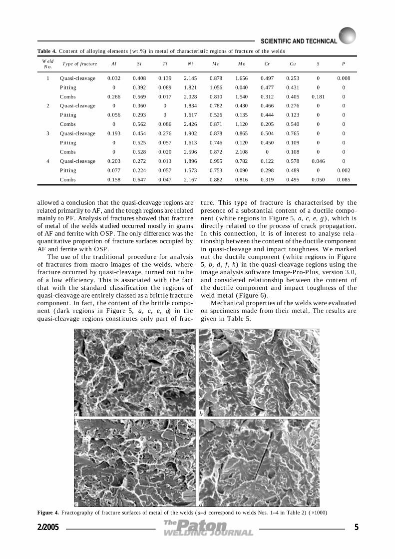
allowed a conclusion that the quasi-cleavage regions arerelated primarily to AF, and the tough regions are relatedmainly to PF. Analysis of fractures showed that fractureof metal of the welds studied occurred mostly in grainsof AF and ferrite with OSP. The only difference was thequantitative proportion of fracture surfaces occupied byAF and ferrite with OSP.
The use of the traditional procedure for analysisof fractures from macro images of the welds, wherefracture occurred by quasi-cleavage, turned out to beof a low efficiency. This is associated with the factthat with the standard classification the regions ofquasi-cleavage are entirely classed as a brittle fracturecomponent. In fact, the content of the brittle compo-nent (dark regions in Figure 5, a, c, e, g) in thequasi-cleavage regions constitutes only part of frac-
ture. This type of fracture is characterised by thepresence of a substantial content of a ductile compo-nent (white regions in Figure 5, a, c, e, g), which isdirectly related to the process of crack propagation.In this connection, it is of interest to analyse rela-tionship between the content of the ductile componentin quasi-cleavage and impact toughness. We markedout the ductile component (white regions in Figure5, b, d, f, h) in the quasi-cleavage regions using theimage analysis software Image-Pro-Plus, version 3.0,and considered relationship between the content ofthe ductile component and impact toughness of theweld metal (Figure 6).
Mechanical properties of the welds were evaluatedon specimens made from their metal. The results aregiven in Table 5.
Figure 4. Fractography of fracture surfaces of metal of the welds (a--d correspond to welds Nos. 1--4 in Table 2) (×1000)
Table 4. Content of alloying elements (wt.%) in metal of characteristic regions of fracture of the welds
WeldNo.
Type of fracture Al Si Ti Ni Mn Mo Cr Cu S P
1 Quasi-cleavage 0.032 0.408 0.139 2.145 0.878 1.656 0.497 0.253 0 0.008
Pitting 0 0.392 0.089 1.821 1.056 0.040 0.477 0.431 0 0
Combs 0.266 0.569 0.017 2.028 0.810 1.540 0.312 0.405 0.181 0
2 Quasi-cleavage 0 0.360 0 1.834 0.782 0.430 0.466 0.276 0 0
Pitting 0.056 0.293 0 1.617 0.526 0.135 0.444 0.123 0 0
Combs 0 0.562 0.086 2.426 0.871 1.120 0.205 0.540 0 0
3 Quasi-cleavage 0.193 0.454 0.276 1.902 0.878 0.865 0.504 0.765 0 0
Pitting 0 0.525 0.057 1.613 0.746 0.120 0.450 0.109 0 0
Combs 0 0.528 0.020 2.596 0.872 2.108 0 0.108 0 0
4 Quasi-cleavage 0.203 0.272 0.013 1.896 0.995 0.782 0.122 0.578 0.046 0
Pitting 0.077 0.224 0.057 1.573 0.753 0.090 0.298 0.489 0 0.002
Combs 0.158 0.647 0.047 2.167 0.882 0.816 0.319 0.495 0.050 0.085
2/2005 5

The studies show that increase in the content ofthe ductile component in the quasi-cleavage regionleads to increase in low-temperature impact toughness(see Figure 6).
To determine the role of this or that structuralcomponent in the brittle fracture process, it is neces-sary to detect them on the fracture surfaces. This wasdone by the special procedure developed for etchingthe fracture surfaces. The problem in this case is that
air bubbles hindering the etching process are presenton a developed rough surface. The ultrasonic dispersergenerating the standing waves in a solution was usedto remove the air bubbles, thus providing a continuouswashing of the fracture surface with an etchant. Alkalisolution of picric acid (picrate) and 4 % solution ofnitric acid in alcohol (nital) were used as an etchant.Microstructure of the weld metal on the fracture sur-face is shown in Figure 7.
Figure 5. Fractography of fracture of weld metals and ductile zones marked in them (b, d, f, h), constituting 15.7 (b), 8.5 (d), 9.7(f) and 8.7 (h) vol.% (a and b, c and d, e and f and g, h correspond to welds Nos. 1--4 in Table 2) (×500)
6 2/2005

The studies revealed that cracks in metal of weld1 propagated mainly in AF, a substantial content ofthe MAC-phase being detected on the fracture surface(Figure 8, a) (VMAC = 3.56 %), which, as noted above,was precipitated along the boundaries of ferrite la-mellae. The MAC-phase was revealed and its volumecontent on the surface of fractured specimens wasdetermined by the method of analysis of images ofthe weld fracture surfaces (Figure 9, b).
Examination of fractographs of fractures of welds2--4 showed that fracture planes propagated both ingrains with the AF structure and in grains whereferrite with OSP was formed. It can be assumed thathere we have two probable mechanisms of crack propa-gation. In the first case the crack propagates acrossthe grains of ferrite with OSP (Figure 10, a), thecarbide phases (MAC-phase in particular) serving asefficient barriers in a way of its propagation. In thesecond case the crack is initiated at the carbide--ferriteinterface and propagates along the boundaries ofgrains of ferrite with OSP (Figure 10, b). As a result,the longitudinal type of carbide particles is fixed onthe fracture surface. No differences in composition ofthe carbide phases with longitudinal and transversepropagation of the crack in grains of ferrite with OSPwere revealed.
Results and discussion. The results obtained al-low an assumption of a probable character of the
mechanism of fracture of the weld specimens. Fractureoccurred by cleavage in a body of the ferrite needlesin the AF grains. As there are high-angle boundariesbetween the needles, the cracks change their propa-gation directions, which leads to formation of a newfracture facet. A change in the crack propagation di-rections requires an additional energy to occur. There-fore, the smaller the size of the needles and the higherthe space disorientation of two neighbouring needlesin the AF grains, the higher the energy required fora crack to propagate and the higher the values ofimpact toughness [8]. A change in the crack propa-gation directions occurs along the boundaries of theferrite needles to form fracture of the comb type onthe surface. As shown by the studies (see Figure 3),the MAC-phase is formed mainly along the boundariesof the ferrite needles. Therefore, we may expect co-incidence of the results of microanalysis of chemicalcomposition of the MAC-phase and combs on the frac-
Figure 6. Effect of volume content V of ductile component in quasi-cleavage regions on impact toughness KCV--60 of welds in low-alloysteels: s ---- results obtained at a temperature of --196 °C
Figure 7. Microstructure of metal of weld No.1 on fracture surfacesin etching in picrate (a) and nital (b) (×2000)
Table 5. Mechanical properties of the welds studied
WeldNo.
Yield stress, MPaTensile strength,
MPaElongation, % Reduction in area, %
Impact toughnessKCV--60, J/cm2
Impact toughnessKCV--173, J/cm2
1 562.0--572.5568.5
701.7--719.1709.1
23.3--27.025.0
69.5--73.170.8
75--120100.6
6.2--9.47.7
2 520.1--520.8564.9
637.8--638.8638.5
26.7--27.727.4
71.4--73.172.0
39--5043.0
2.0--3.12.4
3 562.0--568.9564.9
683.8--693.7688.2
24.0--25.324.7
65.9--76.866.6
48--5952.7
4.8--5.65.2
4 572.4--598.5585.2
720.3--727.3722.6
25.7--26.726.2
67.8--69.769.1
36--4642.7
4.3--5.04.6
No t e . Minimal and maximal values are given in numerator, and average values are given in denominator.
2/2005 7

ture surface. This assumption was experimentallyproved (see Tables 3 and 4).
The presence of the MAC-phase at the ferrite nee-dle boundaries and angle of disorientation of theneighbouring AF needles inhibit the quasi-cleavagefracture process [9]. Analysis of the results shows thatan insignificant increase in the volume content of theMAC-phase (from 0 to 5--6 %) leads to increase in
impact toughness (Figure 11), while at a MAC-phasecontent of more than 6 vol.% the value of impacttoughness decreases. To have a more detailed pictureof the effect of the MAC-phase on impact toughness,it is necessary to study the welds with a higher volumecontent of the MAC-phase. To plot curves for a rangeof high values of the MAC-phase, we used the datagiven in [10] and data obtained experimentally onspecimens in which the volume content of the MAC-phase was approximately 19 %.
The character of relationship between the MAC-phase and impact toughness shown in Figure 11 seemsto be related to a change in the mechanism of its effect
Figure 8. Microstructure with the MAC-phase marked out on the fracture surface of metal of the welds in low-alloy high-strengthsteels (a--d correspond to welds Nos. 1--4 in Table 2) (×3000)
Figure 9. Microstructure of fracture surface of metal of weld No.1(a) (Table 2) and MAC-phase marked out on it (b) (×2000)
Figure 10. Fracture in ferrite with the ordered secondary phase:a ---- propagation of crack across grains of ferrite with OSP (weldNo.1 in Table 2); b ---- propagation of crack along grains of ferritewith OSP (weld No.3 in Table 2) (×2300)
8 2/2005

on initiation and propagation of cracks. If the volumecontent of the MAC-phase is insignificant (up to 5--6 %), it plays the role of a hardening secondary phaseand hampers crack propagation. At VMAC > 5--6 %,the MAC-phase becomes a source of crack initiation,as it contains a brittle component, i.e. martensite(and, probably, retained austenite). Therefore, in-crease in the volume content of the MAC-phase inmetal of the studied welds to more than 5--6 % leadsto decrease in impact toughness.
The change in the mechanism of the effect exertedby the MAC-phase on the fracture process dependsupon its composition. Stresses at the interface betweenthe MAC-phase and ferritic matrix are related to theircomposition, which is caused by their different linearthermal expansion coefficients. Composition of theMAC-phase may affect the stressed state at the inter-face between the phases. As a result, the process ofcrack formation may be either hampered or, on thecontrary, further developed. Unfortunately, our stud-ies did not prove this fact (see Tables 3 and 4), whichseems to be associated with peculiarities of determi-nation of compositions of small particles (less that1 µm). This issue needs to be further investigated.
The fact of decrease in impact toughness of theweld metal with a high (more than 70 vol.%) contentof AF can be explained in terms of the above results.As found in study [11], the amount of the MAC-phasegrows with growth of the volume content of AF inthe weld metal. Our results showed that if the volumecontent of the MAC-phase is in excess of a certainvalue (about 6 % for the welds studied), impact tough-ness of the weld metal decreases. Therefore, the posi-tive effect of AF is levelled out by the negative effectof the MAC-phase. As a result, impact toughness doesnot only increase or remain at the same level, but alsomay markedly decrease (see Figure 1). It is clear thatthe higher the content of carbon or carbide-formingelements, the stronger this effect.
In addition to the content of the MAC-phase, thecharacter of fracture is also affected by the topographyof its distribution. According to the IIW classification[7], in a case where particles of the MAC-phase areparallel to each other and oriented along the ferriteboundaries, this structural component is classed as
ferrite with OSP. It can affect impact toughness ofmetal of the welds in low-alloy steels [12], althoughauthors of this study call it a bainite pack.
The presence of ferrite with OSP on the fracturesurface (see Figure 10, a) allows a conclusion that thismay also be a factor causing instability of low-tempera-ture impact toughness of metal of the welds in low-alloysteels. Analysis of fractures of the welds studied suggeststhat in the case of high values of impact toughness thecrack propagates across the grains of ferrite with OSP(Figure 12), which is characteristic of metal of weld 1.In metal of the welds with low values of impact tough-ness (2--4) the avalanche crack propagation is of a mixedcharacter and occurs both across and along the bounda-ries of ferrite lamellae (see Figure 10, b). A differentlevel of impact toughness in metal of welds 1 and 3(Table 5) is attributable to a different character of crackpropagation.
Upon establishing that the MAC-phase and ferritewith OSP are responsible for decrease in low-tem-perature brittleness of the welds in low-alloy high-strength steels, it was necessary to perform quantita-tive evaluation of the ability of structure of the weldmetal to resist fracture at low temperature. The con-tent of a lamellar component in fracture of the speci-mens determined in impact toughness tests at a tem-perature of occurrence of purely brittle fracture, i.e.--173 °C (Table 5), was selected as such a parameter.To consider this issue, we used a microscopic approachto description of fracture, instead of the traditionalmacroscopic approach. The content of the ductile com-ponent was determined from fractographs of fractures.In addition to the traditional «tough» pitting frac-ture, it allowed also for the ductile component formedin propagation of a crack from one brittle fracturefacet to the other (see Figure 5). A good correlationwas found between the content of the ductile compo-nent in fracture and impact toughness of the weldmetal (see Figure 6).
CONCLUSIONS
1. The MAC-phase on the fracture surface was deter-mined and decrease in impact toughness at low tem-perature was detected using the suggested procedure.
Figure 11. Effect of volume content of the MAC-phase in fractureon impact toughness of weld metal: s ---- according to data of [1];5 ---- results obtained after heat treatment of weld No.1 (heatingto 730 °C and rapid water cooling)
Figure 12. Effect of content of ferrite with OSP on impact tough-ness of welds: I, II ---- regions in which fracture occurs across grainsof ferrite with OSP and in a mixed way, respectively
2/2005 9

2. The procedure for marking out of the ductilecomponent in regions of quasi-cleavage was used toestablish relationship between its content and impacttoughness of metal of the welds in low-alloy steels.It was found that impact toughness increased withincrease in the content of the ductile component inquasi-cleavage fracture.
3. Both MAC-phase and ductile forms of ferrite,in particular ferrite with OSP, may act as a structuralfactor causing instability of properties (such as low-temperature impact toughness) of metal of the weldsin low-alloy steels.
4. To provide a consistently high low-temperatureimpact toughness of the weld metal, it is requiredthat the volume content of the MAC-phase be not inexcess of 5--6 %, and that the content of ferrite withOSP be low.
1. Pokhodnya, I.K., Golovko, V.V., Denisenko, A.V. et al.(1999) Effect of oxygen on formation of acicular ferrite struc-ture in low-alloy weld metal. Avtomatich. Svarka, 2, 3--10.
2. Ito, G., Nakanishi, M. (1975) Study on Charpy impactproperties of weld metals with submerged arc welding. IIWDoc. XI-A-113--75.
3. Svensson, L.-E., Gretoft, B. (1990) Microstructure and im-pact toughness of C--Mn weld metals. Welding Res. Sup-plement, Dec., 454--461.
4. Evans, G.M. (1981) The effect of carbon on the microstruc-ture and properties of C--Mn all-weld-metal deposits. IIWDoc. II-A-546--81.
5. Curry, D.C., Knott, J.F. (1978) Effects of microstructureon cleavage fracture stress in steel. Metal Sci., 12, 511.
6. Garland, J.G., Kirkwood, P.R. (1975) Towards improvedsubmerged arc weld metal. Metal Construction, 7, 275--283.
7. (1986) Guidelines for the classification of ferritic steel weldmetal microstructural constituents using the light microsco-pe. Welding in the World, 24(7/8), 144--148.
8. Romaniv, O.N. (1979) Fracture toughness of structural ste-els. Moscow: Metallurgiya.
9. Ohkita, S., Horii, Y. (1995) Recent development in con-trolling the microstructure and properties of low alloy steelweld metals. ISIJ Int., 35(10), 1170--1182.
10. Evans, G.M. (1984) The effect of heat-treatment on themicrostructure and properties of C--Mn all-weld-metal depo-sits. IIW Doc. A-605--84.
11. Grabin, V.F., Golovko, V.V., Solomijchuk, T.G. et al.(2003) Analysis of structural state of weld metal producedby using welding wires of the ferritic-pearlitic grade. ThePaton Welding J., 8, 17--22.
12. Pokhodnya, I.K., Makarenko, V.D., Korsun, A.O. et al.(1986) Effect of nickel on structure and mechanical proper-ties of weld produced by using basic electrodes. Avtomatich.Svarka, 2, 1--5.
EVALUATION OF THE INFLUENCEOF WET UNDERWATER WELDING CONDITIONSON THE PROBABILITY OF PORE FORMATION
IN THE WELD METAL
S.Yu. MAKSIMOVE.O. Paton Electric Welding Institute, NASU, Kiev, Ukraine
A numerical method was used for evaluation of the influence of hydrostatic pressure, velocity of motion of weld poolsolidification front and hydrogen concentration in the molten metal in wet underwater welding on the value of criticalradius of gas nuclei. Obtained results enable establishing the regularities of the influence of underwater weldingconditions on the susceptibility to pore formation.
K e y w o r d s : underwater welding, pores, solidification rate,hydrogen, pressure, gas nuclei
Porosity is one of the most often found defects inwelds made under the water. In a number of cases,this restrains the underwater welding application. De-spite the importance of the above problem, the issuesof pore formation and influence of the factors, inher-ent in welding directly in the water, have been insuf-ficiently studied and remain to be urgent. One of thesteps in this direction is a mathematical model [1]that allows describing the physical processes, whichproceed in the subsurface layer ahead of the solidifi-cation front (zone adjacent to the interphase) underthe conditions of underwater welding, and enablesstudying the regularities of evolution of the gas bub-bles formed here, and establishing the main parame-
ters of the physical processes that determine furthergrowth or collapse of the nuclei in the weld pool. Themodel was developed with the following assumptions:
• solidification front is a flat surface with a con-stant propagation rate;
• hydrogen transfer is performed only through dif-fusion;
• the liquid is ideal, uncompressed and quiescentover infinity in the absence of thermal convection;
• impurities dissolved in the liquid do not influencethe physical parameters of the liquid medium;
• gas bubble is homogeneous, spherical.Numerical studies conducted with these assump-
tions, led to the following conclusions:• critical parameters of the gas bubble, at which
the bubble growth rate is zero, are chiefly determinedby the external hydrostatic pressure Pa, solidificationfront velocity vs, and cavity formation time t0. Critical© S.Yu. MAKSIMOV, 2005
10 2/2005

condition is unstable: a slight disturbance of the bub-ble parameters leads to an inevitable growth or col-lapse of the cavity;
• bubble growth dynamics is determined by themoment of its initiation. The later the bubble forms,the earlier the concentration field in the subsurfacelayer reaches large dimensions, this eventually in-creasing the amount of hydrogen, diffusing into thebubble cavity, and promoting growth of the latter;
• dynamic characteristics of the gas bubble aheadof the solidification front are largely dependent onthe velocity of the flat front propagation in the entirerange of the possible initial radii of the gas bubble.At increase of the solidification rate, diffusion proc-esses run faster, and critical parameters of gas bubblesshift towards the smaller dimension region.
Investigations showed that in the parameter rangecharacterizing the underwater welding process(depth, solidification rate, hydrogen concentration)there exist certain values of gas bubble radii, at whichtheir growth rate is zero. In the case of a slight increaseof the radius (at other parameters unchanged), thediffusion balance is disturbed, and the gas bubblestarts growing. On the other hand, a slight reductionof the radius leads to compression of the cavity andits subsequent disappearance. Critical radius corre-sponds to an unstable condition of the gas bubble.
The obtained results allows evaluation of the prob-ability of formation of gas bubbles (cavities) in thesubsurface layer (Figure 1). The schematic is a quali-tative representation of an obvious regularity of themost probable formation of small-sized nuclei. How-ever, fine cavities collapse, and larger ones, contrar-ily, grow. Existence of a critical radius (AC line)determines a region (not hatched in the Figure), thearea of which is proportional to the probability ofcavities developing during welding. Numerical studiesenable evaluation of the nature of the influence ofhydrostatic pressure, rate of propagation of the weldpool solidification front and hydrogen concentrationin the liquid metal on the critical radius of gas bubble.This enables outlining the basic approaches to devel-opment of a welding technology with which the criti-cal radius position would shift much farther to theright.
The developed model [1] was used to study theinfluence of the main factors, characterizing the spe-cific features of wet underwater welding, on the criti-cal radius of the bubble. The values of the above
factors varied in the range characteristic for the un-derwater welding conditions.
Figure 2 gives a dependence of the critical radiusof the bubble on the external pressure at differentrates of solidification front propagation. With pres-sure rise, the critical parameter region shifts towardslower values, i.e. the susceptibility to pore formationincreases. It should be noted that increase of the so-lidification rate yields a similar result.
The welding process runs for a certain time duringwhich the subsurface layer is enriched in hydrogenup to its maximum saturation with gas, thus promot-ing the shifting of the critical radii to lower values(Figure 3). The following tendency should be alsonoted: with time each curve of critical parametersasymptotically approaches a certain position, corre-sponding to the moment of time, at which the satu-ration of the subsurface layer is already over. In keep-
Figure 1. Probability B of gas cavity formation ahead of the liquidmetal solidification front
Figure 2. Dependence of the critical radius of gas bubble on externalpressure at different rates of the solidification front: 1 ---- vs == 0.0005; 2 ---- 0.001; 3 ---- 0.002; 4 ---- 0.005 m/s
Figure 3. Dependence of the critical radius of gas bubble on externalpressure at vs = 0.001 m/s for different moments of nuclei formation:1 ---- t0 = 0; 2 ---- 0.1; 3 ---- 0.2; 4 ---- 0.3; 5 ---- 0.5; 6 ---- 1.0 s
1/2005 11

ing with our calculations, maximum hydrogen con-centration in the liquid metal ahead of the movingsolidification front is reached within approximately1 s after the start of its propagation.
Obtained dependencies of critical dimensions ofthe gas bubbles on the propagation rate of the solidi-fication front (Figure 4) enable evaluation of the criti-cal radius at variation of the external static pressure.With its increase in the region of values, where theSiverts law for gas solubility in metal is still valid,the curves of critical radii shift to the lower value
region (Figure 4, a). A certain value of the criticalradius corresponds to each solidification rate. The pat-tern is disturbed at high values of pressure (above1 MPa), when hydrogen solubility in the liquid phasebecomes stabilized. With lowering of the solidifica-tion rate, the slope of the equilibrium curves tendsto zero (Figure 4, b), and at certain values of the ratethe critical points are absent at all.
Dependence of the critical radius of the cavity onthe rate of the solidification front for different mo-ments in time, but at unchanged external pressure, isshown in Figure 5. Note that at low rates the valueof the critical radius is practically independent on themoment of nuclei formation. This leads to the con-clusion that the low rates of solidification are lessfavourable for a broad range of nuclei dimensions,and, therefore, also the number of pores in the weldmetal should decrease.
For any set of initial parameters there exists aquite certain critical value of the dimensions of gasbubbles, formed ahead of the solidification front.With time Rcr is stabilized and remains unchangedfor these welding conditions (Pa, vs).
Figure 6 shows the obtained investigation resultsin the form of dependencies of the critical gas bubbleradius on the solidification rate, hydrostatic pres-sure and hydrogen concentration in the molten met-al in the range of values characteristic for under-water welding.
In the case of 20 cm2/100 g hydrogen content inthe molten weld pool (Figure 6, a) bubbles of 10--15 µm radius can initiate at solidification rate above7 m/h (2⋅10--3 m/s). At slowing down of the solidi-fication process or pressure increase, the probabilityof pore formation decreases, as the critical radius isincreased. 1.5 times increase of hydrogen concentra-tion (Figure 6, b) leads to approximately 2 timesdecrease of the critical radii of the bubbles, and thepressure effect is decreased.
Depending on the solidification rate, there existsa certain pressure level, at which the probability ofpore formation drops abruptly. A section of the curvewhere the angle of inclination of the tangent to theabscissa axis is close to 90° corresponds to this con-dition. The above pressure rises with increase of hy-drogen content. The greatest effect of the action ofthe above factors is found in the range of low solidi-fication rates, and at the rate above 7 m/h theirinfluence is practically neutralized.
The above conclusions correlate well with the re-sults of investigation of the nature of porosity in wetwelding [2]. Study of the fracture of specimens,welded by the rutile and ilmenite electrodes, showedthe presence of micropores of 10--50 µm and absenceof macropores. At decrease of hydrogen content a greatnumber of pores of more than 0.5 mm diameter wereadditionally found.
Increase of the rate of propagation of the solidifi-cation front leads to shifting of the critical parametersof gas bubbles into the region of smaller dimensions,
Figure 4. Dependence of the critical radius of gas bubble on thesolidification front rate at low (a) and high ( b) values of hydrostaticpressure: 1 ---- Pa = 0.1; 2 ---- 0.2; 3 ---- 0.3; 4 ---- 0.5; 5, 6 ---- 1.0;7 ---- 1.5; 8 ---- 2.0 MPa
Figure 5. Dependence of critical radius of the gas bubble on thesolidification front rate for different moments of the time of nucleiformation at Pa = 0.2 MPa: 1 ---- t0 = 1.0; 2 ---- 0.5; 3 ---- 0.3; 4 ----0.2; 5 ---- 0.1 s
12 1/2005

i.e. at low welding speeds the range of dimensions ofnuclei, which grow with time and lead to porosity atweld solidification, becomes smaller.
However, in all the cases with longer of time beforethe bubble initiation, the range of the dimensions ofcavities, where the evolution ends up by pore forma-tion, becomes wider. Critical radii of the bubbles as-ymptotically tend to values, corresponding to the mo-ment of time, at which hydrogen concentration in theliquid metal is stabilized in a region close to the so-lidification front.
Allowing for the experimental dependencies of hy-drogen solubility in the liquid metal with increase ofthe external pressure leads to a complex dependenceof the critical radius on the pressure, at which weldingproceeds. At shallow depths pressure rise promotesshifting of the critical radius into the region of smalldimensions of the gas bubbles. At great depths, whichare characterized by increase of gas solubility in themetal, a reverse tendency has been noted: pressurerise results in an increase of the critical radius, thefurther evolution of which leads to pore formation.
As under the actual conditions, only two parame-ters can be regulated (solidification rate and hydrogenconcentration), porosity can only be reduced by de-creasing their values. One of the efficient methods toimplement such an approach can be stirring of theweld pool molten metal. The action is produced onboth the factors simultaneously. On the one hand,stirring promotes degassing of the weld pool, and onthe other ---- equalizing of the molten metal tempera-ture over the entire volume, thus causing a loweringof the solidification rate. In practice, when underwa-
ter welding is performed, this can be achieved usingan external electromagnetic action, or applying trans-verse oscillations of the electrode end or welding head.
1. Maksimov, S.Yu., Gurzhy, A.A. (2004) Modeling the con-ditions of pore initiation in the weld metal in wet underwa-ter welding. The Paton Welding J., 7, 7--11.
2. Shiming, L., Guorong, W., Yonglun, S. et al. (1987) Astudy of microporosity in underwater wet welding. IIWDoc. CREAU 96--87.
Figure 6. Influence of pressure on the critical radius on the gasbubble at hydrogen concentrations of 20 (a) and 30 (b) cm3/100 g:1 ---- Pa = 0.1; 2 ---- 0.2; 3 ---- 0.3; 4 ---- 0.5 MPa
1/2005 13

PORE FORMATION IN WELD METALIN SUBMERGED ARC WELDINGWITH SURFACE SATURATIONOF GRAINS WITH FLUORINE
V.G. KUZMENKO1 and V.I. GUZEJ2
1E.O. Paton Electric Welding Institute, NASU, Kiev, Ukraine2City State Administration, Kiev, Ukraine
Properties were studied of fused welding fluxes of manganese-silicate type, not containing fluorine and subjected tofluorinating heat treatment together with ammonia salt of hydrofluoric acid (NH
4F) and magnesium hexafluosilicate
(MgSiF6). It is established that the weld metal resistance to pore formation is achieved, when using 0.5 % each of the
above salts for flux treatment. Fluorine content in the flux is equivalent to adding 0.4 % CaF2 to it. The effect is
achieved due to local arrangement of fluorine on the flux grain surface.
K e y w o r d s : arc welding, fluxes, gas shielding, porosity,fluorinating heat treatment, nitrogen dissolution
Porosity in the weld metal appears because of exces-sive solubility of mainly nitrogen and hydrogen fromthe ambient gas atmosphere in the molten metal andrelease of these gases during cooling down and solidi-fication of the weld metal [1, 2]. It is possible toprevent porosity in submerged arc welding by regu-lating a set of physical phenomena including slag andgas shielding of the weld pool.
Slag shielding of the weld pool is based on thecommonly accepted idea on existence of the air-tightshell around arc. However, this shield solely is notenough. In [3] it is shown that a continuity of theslag shell is destroyed in the zone of the pre-arc frontof the parent metal melting due to a fast shift of theliquid slag under the action of high-velocity gas-plasma flows of the arc towards the rear area of theweld pool. As a result the efficiency of the slag shield-
ing of the molten metal decreases while that of thegas shielding grows.
Introduction of CaF2 into the flux compositionproduces the best results for decrease of a level of gassolubility and restriction of the weld metal porosityunder electric arc welding. Hence, addition of 3--5 wt.% of this salt into the manganese-silicate fluxdecreases nitrogen concentration in the weld metal2--3 times [4], thus increasing its resistance againstpore formation. Initially it was considered that intro-duction of fluorides into flux increased the efficiencyof shielding from the air due to a decrease of the slagviscosity and, thus faster formation of the slag «shel-ter» on the surface of the weld pool. A specific roleof the gaseous silicon tetrafluoride SiF4 formed underinteraction of CaF4 and SiO2 contained in fluxes isestablished in [5]. Peculiarities of this reaction di-rectly between these components as well as in com-position of the welding fluxes are considered in [6--8].Even under normal temperature this gas creates pres-sure of about 400 kPa (40 atm) [9] rather quicklyexpelling the air from the arc zone.
Calcium fluoride performs a double function inthe welding fluxes. On the one hand, it affects suchphysical-chemical properties of fluxes as melting tem-perature, viscosity, solid-liquid interfacial tension,electrical conductivity, activity of the componentsexerting through them a metallurgical influence onthe metal. On the other hand, it provides a gas shield-ing due to formation of SiF4. It is noteworthy thatthe necessary physical-chemical properties are pro-vided by a uniform distribution of the components inthe volume of the welding fluxes while SiF4 is formedon the surface of the flux grains. A surface nature ofSiF4 isolation is confirmed by the data from [8] wherethe method of flows was used to study a formationintensity of this gas as a function of temperature.Fluxes were heated from 400 °C up to melting tem-perature. The quantity of this gas monotonously grewwith heating with a considerable increase right beforemelting and a sharp decrease after flux was melted.A surface nature of SiF4 formation is also confirmedby the fact that this gas is released in a greater quantity© V.G. KUZMENKO and V.I. GUZEJ, 2005
Figure 1. Intensity of SiF4 release (a) from different parts of theflux charge in the specific zones of the weld pool (b) [6]: l ----length of the weld pool
14 2/2005

from pumice-like fluxes than from glass fluxes. Thepumice-like fluxes also provide a higher weld metalresistance against pore formation in welding.
Comparison of the SiF4 release from the parts offlux charge in specific zones of the weld pool (Fi-gure 1) shows that its maximal quantities will formin the pre-arc zone on the upper front of the metalmelting, i.e just where there is a break of the slagshell continuity in the weld pool. Considering thatpenetration of the air into the weld pool is most prob-able specifically in this zone it seems appropriate tointensify the process of SiF4 formation on the surfaceof flux grain. A current technology, which providesa uniform distribution of fluorine in the volume offlux grain, does not allow a local increase of its surfaceconcentration.
Previously we studied the fluorinating treatmentof fluxes for its effect on the change in the nature oftheir hydration [10]. Formation of the fluoride barrieron the flux grain surface essentially decreases the fluxtendency to moisture absorption. One can assume thatan increased content of fluorides in the surface layerof the flux grain can also influence the pore formationin the weld metal during welding.
A layer enriched with fluorine and depleted withoxygen forms on the surface of the flux grains duringheat treatment with gaseous hydrogen fluoride. Evi-dently, such treatment of fluxes containing silica cre-ates conditions for its more intense interaction withfluorides, so that gaseous silicon tetrafluoride formsmore rapidly. We experimentally studied the fluori-nating heat treatment of fluxes for its effect on resis-tance of the weld metal against pore formation re-sulted from corrosion. For this purpose a fluorine-freeflux of the manganese-silicate type approaching in itscomposition the standard flux of AN-60 grade wasfused in the electric flux furnace. This flux was thenexposed to fluorinating heat treatment in the closedcontainer together with 1.5, 3.0 and 4.5 wt.% of am-monium fluoride NH4F at the temperature 500 °C for39 min. Chemical composition of fluorine-free fluxand the fluxes received after fluorinating heat treat-ment is shown in Table 1.
Analogous control fluxes with the fluorine contentdifferent from that of the fluorinated fluxes and ap-proaching it were produced by the conventional tech-nology introducing CaF2 into the molten charge. Chemi-cal composition of these fluxes is shown in Table 2.
Fluorinated and control fluxes were used for depo-sition on the St3 steel plate 16 mm thick with groovesfilled with the measured quantity of the air-dry rust[4]. A mass of rust per 100 mm when pores wereformed in the deposited metal was assumed as theporosity threshold. Deposition was made with wireSv-08A 4 mm in diameter under the following condi-tion: welding AC Iw = 750--800 A; arc voltage Ua == 37--40 V; welding speed vw = 25 m/h.
The experimental results are shown in Figure 2.Fluorine was introduced through the gas phase byfluorinating treatment into the fluxes designated withcurve 1 and by the conventional technology (by in-troduction to the charge) into the fluxes designatedwith curve 2. The quantity of rust when pores ap-
peared in the weld metal was 3--5 times higher forfluorinated fluxes than for fluxes produced conven-tionally. Most likely such high indices are specifiedby a more intensive formation of silicon tetrafluoridebecause the corresponding reagents are present on thesurface of the flux grains. Using the fluorinationmethod we produced a series of manganese-silicatefluxes with a lower fluorine content to obtain thebalanced indices for the weld metal resistance againstporosity and for the quantity of the formed gaseousfluorides. Chemical composition of fluorine-free andfluorinated fluxes produced with introduction of asmaller NH4F quantity is presented in Table 3.
The method of flow with titrimetric ending wasused to determine the weight fraction of SiF4 isolated
Figure 2. Tendency of the weld metal to pore formation duringwelding using fused flux produced by different technologies de-pending on the content of CaF2 in their composition: 1 ---- surface-fluorinated fluxes (see Table 1); 2 ---- fluxes produced by fusionof all components in the electric furnace (see Table 2); K ---- massof rust per 100 mm of the weld length
Table 1. Chemical composition (wt.%) of fluorine-free flux andthe fluxes received after application of the fluorinating heattreatment
Weightfraction
ofNH4Fin flux,
%
SiO2 CaF2 CaO MnO Al2O3 Fe2O3 S P
0(AN-60)
46.2 -- 9.4 37.2 4.0 0.02 0.03 0.02
1.5 46.1 1.3 7.7 37.3 4.2 0.02 0.03 0.023.0 45.4 2.7 6.5 37.4 4.1 0.02 0.03 0.024.0 45.8 3.8 6.2 36.8 3.9 0.02 0.03 0.02
Table 2. Chemical composition (wt.%) of fluxes of manganese-silicate type with different content of CaF2
Weightfractionof CaF2in flux,
%
SiO2 CaF2 CaO MnO Al2O3 Fe2O3 S P
2.0 46.2 1.4 9.8 38.7 4.3 0.04 0.02 0.033.0 45.9 2.3 9.9 38.3 4.3 0.03 0.03 0.024.5 45.7 3.9 10.3 38.4 4.2 0.03 0.03 0.026.0 45.5 5.0 9.8 38.2 4.3 0.03 0.02 0.04
2/2005 15

from the fluorinated fluxes (Table 3) and from thestandard flux AN-60 under heating within the tem-perature range 600--900 °C. The results presented inFigure 3 show that more SiF4 was released from fluxesafter fluorinating treatment (surface-fluorinated (SF)fluxes) with 0.5 % NH4F than from the standard ones.Hence, it is quite possible to produce fluxes withessentially lower content of fluorine arranged on theflux grain surface providing resistance of weld metalagainst porosity on par with the standard flux AN-60.To verify this assumption the resistance of weld metalagainst rust porosity in welding with fluorinatedfluxes was studied by the above-described method.These fluxes were produced by heating the pumice-like fluorine-free manganese-silicate flux with 0.1,0.2, 0.4, 0.6 and 1.0 wt.% of NH4F. Welding speedwas 30, 34.5 and 40 m/h. The standard flux AN-60was used to conduct control tests. The results of theexperiment are shown in Figure 4. With all used vari-ants of changing NH4F content above 0.48 wt.% inthe mixture under fluorinating treatment and withall welding speeds the fluorinated fluxes displayedhigher resistance of weld metal against crust porositythan the standard flux AN-60. This index increaseswith the weight fraction of NH4F in the mixture.
Gaseous SiF4 may also be used as a fluorinatingreagent in addition to HF (a product of thermal de-composition of NH4F). In this case magnesiumhexafluosilicate MgSiF6 may be the source of this gas.Fluorine-free flux of AN-60 type (see Table 3) wastreated by the previously employed technique in themixture with MgSiF6 at the temperature 500 °C.Weight fraction of salt in the mixture with the flux
in terms of SiF4 was 0.25, 0.50, 0.75, and 1.00 %.Such fluxes were used to determine the resistance ofweld metal against rust porosity by the previouslydescribed method. Conditions of the experiment andthe used materials were similar to those employedearlier (except vw = 21.5 m/h). The results of theexperiment are shown in Figure 5. Indices of weldmetal resistance against rust porosity equal to thosefor flux AN-60 are obtained by using the test fluxtreated with 0.4 wt.% SiF4. Further increase of thereagent content under fluorinating treatment did notlead to essential increase of the weld metal resistanceagainst pore formation.
Increase of the SiF4 formation intensity underwelding heating of fluorinated fluxes should facilitatea more ample use of fluorine in welding. Depositionwith test fluxes obtained by treatment with 0.4, 0.5,1.0 and 1.5 wt.% NH4F and standard flux AN-60 wasperformed for estimation of the value of this index.Then the fluorine content was determined in the initialflux and in the slag crust.
These data are presented in Table 4 and in Fi-gure 6. They suggest that the efficiency of using fluo-rine of SF fluxes essentially exceeds this index in thestandard fluxes.
Therefore, fluorinating treatment of fluxes resultsin a considerable increase of the weld metal resistanceagainst porosity in welding. However, this effect isachieved under fluorine content being 10 times lowerthan that provided by conventionally produced fluxes.
The use of ammonium salts of hydrofluoric acidas an HF-forming reagent under fluorinating heattreatment of the welding fluxes may lead to an in-
Figure 4. Tendency of the weld metal to formation of porosity in weldingat different speeds using SF fluxes (see Table 3) depends on the contentof NH4F used for their fluorating treatment: 1, 1′ ---- vw = 30; 2, 2′ ----34.5; 3, 3′ ---- 40 m/h; 1--3 ---- SF; 1′--3′ ---- AN-60 flux
Figure 3. Effect of temperature on intensity of the SiF4 release fromfluxes with different content of CaF2, wt.%: 1 ---- 0.22 (SF); 2 ----5.70 (AN-60); 3 ---- 0.84 (SF); 4 ---- 0.84 (SF); 5 ---- 1.28 (SF)
Figure 5. Dependence of weld metal resistance against pore for-mation in welding using SF fluxes on the content of SiF4 producedunder thermal decomposition of MgSiF6 in the mixture with fluo-rine-free flux: 1 ---- SF; 2 ---- AN-60 flux
Table 3. Chemical composition (wt.%) of initial and fluorinatedfluxes obtained as a result of heat treatment with a limitedweight fraction of NH4F
Weightfraction ofNH4F influx, %
SiO2 MnO CaF2 CaO Fe2O3
0(AN-60)
45.3 36.5 -- 8.9 0.28
0.4 45.1 36.9 0.22 7.9 0.260.6 45.0 36.7 0.48 8.2 0.231.0 44.8 37.2 0.84 7.7 0.221.5 44.3 36.9 1.28 7.9 0.32
16 2/2005

crease of the nitrogen content in their compositiondue to thermal decomposition of ammonia. This in itsturn may foster transition of nitrogen from the fluxinto weld metal in the course of welding. Figure 7shows the results of determination of the nitrogencontent in the standard flux AN-60 and fluxes of SFtypes produced by fluorinating technology by intro-duction of ammonium fluoride into the flux mixturein the range of 0 up to 1.5 % and subsequent heattreatment. As it is seen from the Figure, the contentof nitrogen in the flux inconsiderably increases withammonium fluoride in comparison with the standardflux AN-60 and amounts to 0.011--0.016 wt.%. None-theless, we carried out a final verification by controlwelding and determination of the nitrogen content inthe weld metal. The air nitrogen was also studied inthese experiments for its effect on metal saturationwith nitrogen in the course of welding when fluxeswith different bulk weight were used. The results ofthe experiments are shown in Figure 8. They provethat the nitrogen dissolution in the weld metal causedby fluxes treated with ammonium fluorides is smalland less essential than its nitration by the air nitrogen.
CONCLUSIONS
1. The absence of a reliable slag «shelter» of the weldpool in submerged arc welding requires strengtheningof gas shielding for the weld metal with the aim ofpreventing pore formation.
2. Increase of the fluorine content in the surface layerof grains of manganese-silicate fluxes to the level whenits total content is within 0.5--1.5 % in terms of CaF2facilitates SiF4 formation under heating in welding.
3. High-silica, fluorine-free and pumice-like fluxesexposed to fluorinating heat treatment at 500 °C in themixture with 0.5 wt.% NH4F or with the same quantity
of MgSiF6 are on par with standard flux AN-60 resistantagainst formation of rust porosity in welding.
1. Podgaetsky, V.V., Lyuborets, I.I. (1984) Welding fluxes.Kiev: Tekhnika.
2. Pokhodnya, I.K. (1972) Gases in welds. Moscow: Mashi-nostroenie.
3. Kuzmenko, V.G. (1998) About continuity of slag envelopein submerged arc welding. Avtomatich. Svarka, 3, 14--19.
4. Lyubavsky, K.V. (1948) Metallurgy of automatic sub-merged arc welding of low-carbon steel. In: Problems oftheory of welding processes. Moscow: Mashgiz.
5. Podgaetsky, V.V. (1953) Reactions in arc atmosphere insubmerged arc welding. Avtomatich. Svarka, 1, 10--12.
6. Podgaetsky, V.V., Novikova, T.P. (1960) About emission ofsilicon fluoride in heating of flux during welding and dry-ing. Ibid., 6, 19--22.
7. Bratland, D., Fekri, A. et al. (1970) Vapour pressure ofsilicon tetrafluoride above mixtures of fluorides and silica.Acta Chemica Scandinavica, 24, 846--870.
8. Kuzmenko, V.G. (1980) Peculiarities of reaction in mixturesof calcium fluoride and silica. Avtomatich. Svarka, 4, 33--35.
9. Ryss, I.G. (1956) Chemistry of fluorine and its inorganiccompounds. Moscow: Goskhimizdat.
10. Kuzmenko, V.G., Guzej, V.I. (2004) Hydration of fluxeswith a locally-changed chemical composition of grains. ThePaton Welding J., 6, 41--43.
Figure 8. Dependence of the nitrogen content in the weld metalproduced by using SF fluxes with bulk weight 1.3 (1), 1.0 (2),0.7 (3) kg/dm
3 on the content of NH4F: solid curve ---- SF;
dashed ---- AN-60 flux
Table 4. Efficiency of using fluorine in the fluxes in welding
Weight fraction ofNH4F in flux, %
Weight fraction of CaF2, % ∆F--, % ∆F--/F--, %Threshold of pore
formationIn flux In slag crust
0 (ÀN-60) 5.70 4.84 0.43 15.1 0.40.4 0.22 0.10 0.06 54.4 1.00.6 0.48 0.17 0.16 66.6 1.31.0 0.84 0.28 0.29 69.0 1.81.5 1.28 0.32 0.46 71.8 2.4
No t e . ∆F-- ---- weight fraction of released fluorine; F-- ---- total weight fraction of fluorine in flux.
Figure 6. Efficiency of the use of fluorine in welding with SF (1)and AN-60 (2) flux
Figure 7. Nitrogen content in SF fluxes as a function of ammoniumfluoride content (1, 2 ---- see Figure 6)
2/2005 17

INFLUENCE OF THE DIMENSIONS OF A SPECIMENOF ALUMINIUM ALLOY WELDED JOINT ON THE
RESIDUAL STRESSED STATE AND FATIGUE RESISTANCE
V.A. SHONIN, O.I. GUSHCHA, V.S. MASHIN, V.S. KOVALCHUK and A.Z. KUZMENKOE.O. Paton Electric Welding Institute, NASU, Kiev, Ukraine
The paper presents the results of evaluation of residual stresses in butt welded joints of aluminium alloy AD33 (6061)6 mm thick on specimens of different width (70--600 mm) produced by TIG and MIG welding processes. Experimentsare used to demonstrate the influence of longitudinal and transverse tensile residual stresses on the strength and fatiguelife of welded joints with a transverse weld under axial load.
K e y w o r d s : aluminium alloys, butt welded joints, fatigueresistance, strength, fatigue life, residual welding stresses,stress concentration, specimen dimensions
Design fatigue resistance values of welded joints aredetermined mostly using the data of testing for axialcyclic load of one-type large-sized or laboratory speci-mens, in which the factors inherent in welded struc-tures are taken into account to an utmost degree [1--9].In a number of cases, also narrow samples are used(welded separately, or cut out of a large blank), whichin the general form reproduce the shape and structuralcondition of the joints, typical for the used weldingprocesses and modes. However, a certain degree ofambiguity is still present in selection of the dimensionsof specimens for fatigue testing in terms of allowingfor their residual stressed state.
Problem analysis. Presence of residual stresses inmetal structures is the consequence [10--16] of a non-uniform thermal impact under the conditions of fusionwelding. Residual stresses develop as a result of alongitudinal and transverse shortening of the metalat its cooling following the plastic thermal compres-sion in the HAZ and weld shrinkage. The level oflongitudinal and transverse residual stresses rises withreduction of the dimensions of an active temperaturefield relative to the length, width and thickness ofthe plates being welded [15, 16]. Therefore, the natureof distribution of the residual welding stresses de-pends not only on the dimensions of the parts beingjoined, but also on the welding process. Fatigue re-sistance is influenced by the surface residual stressesin the zone of the geometrical stress raiser, the natureof distribution of which is determined by the longi-tudinal and transverse components.
For welded joints of aluminium alloys it was ear-lier [5, 17--19] experimentally established that in com-bination with the geometrical stress raiser, the highestdamaging action is produced by the residual stressesof the direction which coincides with the externalloading stresses. Fatigue life of transverse joints withuntreated welds is markedly reduced at increase ofthe level of tensile residual stresses, which are trans-
verse relatively to the weld. Their action is similarto the static component of cyclic stresses, which re-sults in an increase of the effective coefficient of cycleasymmetry in the stress raiser zone [3].
In wide welded samples with continuous weldsthe high transverse tensile residual stresses (in themiddle part of the specimen) are induced at higherheat input and low welding speed (for instance, man-ual TIG welding). They are balanced within the entirewidth of the plate in the longitudinal section of theweld. The level of these transverse residual stressesin the HAZ is up to the maximum value at plate sizeof more than 500 × 500 mm [10, 13, 14]. Such con-ditions of development of high transverse tensile re-sidual stresses are characteristic also for the case ofmaking short welds, in which the length is muchsmaller than the plate width (for instance, weldingof small-sized parts to the main element).
High level of transverse tensile residual stresses inthe subsurface layers of the HAZ metal also developswhen making multilayer welds (more than four passes)in thick-walled structural elements [5, 11]. However,in this case the residual stresses are equalized withinthe metal thickness and are little dependent on the widthand length of the plates being welded.
With all the variants of fusion welding the longi-tudinal tensile residual stresses, balanced in the trans-verse section of the joint, have higher values than thetransverse tensile residual stresses. They do not de-tract from the joint fatigue life with an unremovedweld convexity at cyclic load application along theweld, due to the minimum concentration of stressesin this direction. Damaging influence of the longitu-dinal tensile residual stresses is maximum in the jointswith crossing welds [1], when the longitudinal weldwas the last one to be made, which results in devel-opment of tensile residual stresses across the previousweld. Such cases are not typical for the welded struc-tures. The role of the longitudinal component of thetensile residual stresses under the action of externalstresses applied across the weld has not been com-pletely clarified.
© V.A. SHONIN, O.I. GUSHCHA, V.S. MASHIN, V.S. KOVALCHUK and A.Z. KUZMENKO, 2005
18 2/2005

Incomplete data on the nature of distribution ofthe transverse and longitudinal residual stresses inspecimens tested for fatigue and the actual structures,as well as ambiguous interpretation of experimentaldata on their influence on the fatigue life, have becomereflected in the norms of steel structure strengthanalysis [7, 9]. These norms do not precisely specifythe direction of the longitudinal and transverse com-ponents of the tensile residual stresses relative to theexternal loading stresses. Such a simplified approachbased on the maximum damaging influence of thetensile residual stresses, is proposed for applicationalso during development of the norms of aluminiumstructure design [20]. In this case, the possibilities ofimprovement of welded structure design by inducingin them a more favourable combination of residualstresses with external load stresses [15] are not takeninto account. Application of highly-efficient processesof continuous welding, which lead to a considerablenarrowing of the HAZ, is the main condition for asignificant lowering of the transverse tensile residualstresses in the aluminium structure joints [6].
This created the need for assessment of the influ-ence of the actual residual stresses, caused by a changeof welded joint dimensions and the welding process,under the condition that the longitudinal componentis much larger than the transverse component of theresidual stress. This is required to establish such di-mensions of specimens of aluminium alloy weldedjoints, made by high-efficient fusion welding proc-esses, that would be sufficient for fatigue testing, andgetting a reply to the question of the rationality oftaking additional measures to induce transverse ten-sile residual stresses in the welded joint.
The purpose of this study was evaluation of theinfluence of a welded specimen dimensions on thefatigue resistance of butt welded joints of aluminiumalloys in its interrelation with the transverse and lon-gitudinal components of the tensile residual stressesfor the case of application of high-efficient TIG andMIG welding processes.
Materials and methods of investigation. Investi-gations were performed on specimens of butt jointsof AD33 T1 alloy (6061 T6) 6 mm thick. The appear-ance of the specimen for fatigue testing and its di-mensions are shown in Figure 1. The specimen blankswere welded separately across the rolling directionwithout edge preparation in one pass in the downhandposition. Specimens 200 and 500 mm wide werewelded one blank at a time, and specimens 70 mm
wide were welded as a packet of 3 to 6 blanks takingthe weld start and finish sections to the run-on andrun-off tabs. Two automatic welding processes wereused, namely consumable electrode (MIG) in a mix-ture of inert gases (Ar + He) and nonconsumableelectrode (TIG) in argon. The joints were made using1.6 mm welding wire of alloys SvAMg5 and SvAK5.
MIG welding was performed with backward in-clined electrode at an angle of 80° to the weld axis.Edge preparation for welding met the requirementsof NFA 87010 standard. A steel backing was used toform the convexity on the reverse side of the weld(in keeping with the recommendations of NFA 89220standard). Weld quality was not lower than that ofthe second class. MIG welding was performed usinga DC power source VDU-506 (rated welding currentof 500 A), pulsed current converter OI-122 and weld-ing machine A-1431.
TIG welding was conducted using I-126 powersource with automatic welding machine AS-TV-2Mand 6 mm diameter tungsten electrode.
Welding modes are given in Table 1.Residual longitudinal σres
x and transverse σresy
stresses in specimens of medium thickness were de-termined using a nondestructive acoustic measure-ment method, based on measurement of the velocityof ultrasound propagation in the metal, depending onits loading condition [14, 21]. Measurements wereconducted using a portable device, developed at theE.O. Paton Electric Welding Institute. The error ofthe measured stress level was not higher than 10 %of the base metal yield point. Measurement base ofthe longitudinal and transverse residual stresses wasdetermined by the transducer dimensions (7 × 7 mm),
Figure 1. Welded specimens for fatigue testing
Table 1. Welding modes
Welding process Wire typeWelding
current Iw, AArc voltage Ua,
VWire feed rate
vf, m/hWelding speed
vw, m/h
Gas flow rate, l/min
Ar He
MIG SvAMg5 300--320 24--25 350--360 38 20 20
SvAK5 300--320 24--25 350--360 38 20 20
TIG SvAMg5 430--440 10--11 85 8 20 --
SvAK5 430--440 10--11 85 8 20 --
2/2005 19

which was a square-shaped acoustic transducer. Val-ues of residual stresses were measured in sections par-allel to the weld axis, that ran through the HAZ andnormal to the weld in the specimen central part. Tobring the transducer as close as possible to the fusionzone, it was fastened on the specimen surface fromthe side of the weld root. In one section of the speci-men, the measurements were taken in 7--15 points,depending on its width and anticipated stress gradi-ent. Residual stresses were measured in welded blanksand initial specimens before testing; their results arepresented in the generalized form in Figures 2--5. Todetermine the residual stresses in the immediate vi-
cinity of the fusion zone (at 2 mm distance from theweld boundary) a method of strain gauge measure-ment with gauges with a 5 mm base was also used.Residual stresses in the direction of the metal thick-ness (Figure 2) were not considered, as on the surfaceσres
z = 0.Coefficient of stress concentration in the joints,
which is due to the geometry of weld profile, wascalculated by the known dependencies allowing forthe recommendations given in [22]. Used for this pur-pose was the statistical data of measurement of themain parameters of weld profile, namely radius ρ andangle θ of fillet surface on the weld boundary, as well
Figure 2. Transverse σresy (a, b) and longitudinal σres
x (c, d) residual stresses in specimens 200 m wide produced by MIG welding withapplication of SvAMg5 (curves) and SvAK5 (dots) wires: a, c ---- section along the HAZ; b, d ---- section across the weld along thespecimen axis; dashed curves ---- average values of 12 measurements; solid curves ---- limits of measurement data scatter
20 2/2005

as weld height h and width b. These parameters weremeasured in blanks and specimens produced by dif-ferent processes, and in different welding modes,namely by direct measurement method (profile meas-urement with the scale factor of 0.01 mm) and replicamethods using plastic moulds and measurement in atool microscope at 10-fold magnification of the cutmould profile. Obtained results are given in Table 2.
Fatigue testing of one-type of welded specimensof butt joints was conducted by applying axial cyclic
loading at a cycle asymmetry coefficient of a constantsign, Rσ = 0.1 s with loading frequency of 4--7 Hz.Each test series included not less than eight specimensof one type. Considering the great range of their width(70--500 mm) their testing was performed using elec-trohydraulic machines URS-20 and Schenk-100 (RS-1.0) fitted with a dynamomeasuring device with loadmeasurement error of ±1 %. Specimens of considerablewidth were tested using a hydraulic machine of pul-sator type TsDM-200. The cyclic loading mode of this
Figure 3. Transverse (1, l) and longitudinal (2, m) residual stresses in specimens 200 mm wide produced by TIG welding withapplication of SvAMg5 (a, b) and SvAK5 (c, d) wires: a, c ---- section along the HAZ; b, d ---- section across the weld along thespecimen axis; 1, 2 ---- average values from 3 measurements by acoustic method; dashed curves and points ---- data of strain gaugemeasurements
2/2005 21

machine was set by the specimen stresses using straingauges with 10 mm base. Gauges were symmetricallypasted in four points on the surface of the specimenworking zone 10 mm from the weld boundary. Toreduce a non-uniform distribution due to a concen-trated application of the load, two-sided coverplateswere used in the testing machine grips. The cover-plates were cut out of the base metal to suit the di-mensions of the specimen grip part. They were joinedto the specimen end faces by transverse fillet welds.
Fatigue testing results were presented by values ofthe range of nominal stresses 2σa and fatigue life tocomplete fracture of the welded joint.
A series of welded specimens 200 mm wide withartificially induced high tensile residual stresses inthe HAZ located in the central part of the weldedjoint were also prepared. A point heating method wasapplied to induce in the HAZ transverse tensilestresses, comparable in their level to the longitudinaltensile stresses. Heating was performed with a gas
Figure 4. Longitudinal (1) and transverse (2) residual stresses in specimens 300 (a) and 600 (b, c) mm wide produced by MIG weldingwith application of SvAMg5 wire: a, b ---- section along the HAZ; c ---- section across the weld along specimen axis; dots ---- averagevalues of 3 measurements
22 2/2005

torch up to the temperature of about 250 °C at acertain distance from the weld with additional heatremoval from the heating zone vicinity, using a cir-cular copper coverplate, cooled by running water.Such a treatment did not cause an overall warping ofthe specimen, while the transverse residual tensilestresses in this case rose from 45 up to 130 MPa.
The main mechanical properties at testing by one-time static tension of the base metal and welded jointsmade by different welding processes, were determinedon specimens of a standard width (b = 15 mm). Tensiletesting was also performed on wide specimens (b == 70 and 200 mm). UME-10, UE-50 and Schenk-100(RS-1.0) all-purpose machines were used. Yield pointof specimens of width b = 70 and 200 mm was evalu-ated using extensometer with base LE0
= 100 mm, and
for narrow ones (b = 15 mm) ---- LE0 = 25 mm. At
evaluation of standard relative deviation δ5 for widespecimens the calculated measurement length (L0 == 5.65√Bt) was much greater than the width of theHAZ metal. Relative elongation δ50 mm on the base ofL0 = 50 mm, which corresponded to the maximumHAZ width, was also determined. Average values ob-tained at testing three or more specimens are givenin Table 3.
Investigation results. Mechanical properties ofthe welded joint. Testing of welded joint specimensby short-time tension demonstrated the following: ul-timate strength σt is by 30 %, yield point σ0.2 by 50 %,relative elongation δ5 by more than 2 times, δ50 mm by21 % lower than the respective characteristics of thebase metal (see Table 3). Such a lowering of the
Figure 5. Transverse (1, l) and longitudinal (2, m) residual stresses in specimens 70 mm wide produced by MIG (curves) and TIG(dotted curves) welding with application of SvAMg5 wire: a ---- section along the HAZ; b ---- section across the weld along the specimenaxis; dashed curves ---- average values from 6 measurements; solid curves ---- limits of measured data scatter; dots ---- results of isolatedmeasurements
Table 2. Parameters of weld convexity and design coefficient ασ of stress concentration in specimens
Weldingprocess
Wiretype
Weld side
Face Root
ρ, mm θ, deg b, mm h, mm ασ ρ, mm θ, deg b, mm h, mm ασ
TIG SvAMg5 1.130.22
17.62.2
16.902.60
1.670.18
1.500.06
0.760.30
35.07.4
7.900.36
1.380.16
1.760.16
SvAK5 1.320.91
26.06.4
21.206.45
1.390.19
1.720.39
0.720.24
36.95.5
7.800.52
1.380.13
1.790.14
MIG SvAMg5 1.100.32
18.93.2
17.400.46
1.730.27
1.550.09
0.380.21
51.39.7
4.700.65
1.770.31
2.430.67
SvAK5 0.730.65
24.46.9
17.100.88
1.480.25
1.910.34
0.660.53
46.77.3
4.951.90
1.660.31
2.000.40
No t e . Numerator gives the average value, and denominator ---- the standard deviation.
2/2005 23
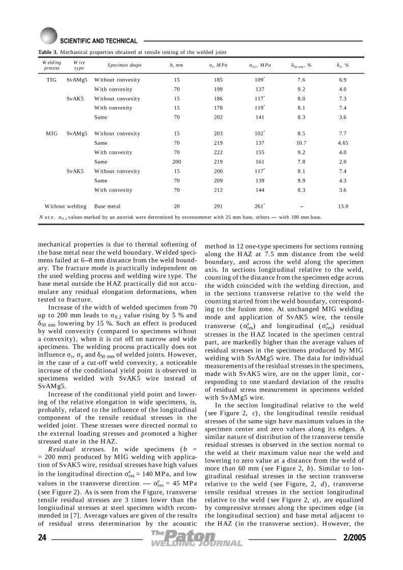
mechanical properties is due to thermal softening ofthe base metal near the weld boundary. Welded speci-mens failed at 6--8 mm distance from the weld bound-ary. The fracture mode is practically independent onthe used welding process and welding wire type. Thebase metal outside the HAZ practically did not accu-mulate any residual elongation deformations, whentested to fracture.
Increase of the width of welded specimen from 70up to 200 mm leads to σ0.2 value rising by 5 % andδ50 mm lowering by 15 %. Such an effect is producedby weld convexity (compared to specimens withouta convexity), when it is cut off on narrow and widespecimens. The welding process practically does notinfluence σt, σy and δ50 mm of welded joints. However,in the case of a cut-off weld convexity, a noticeableincrease of the conditional yield point is observed inspecimens welded with SvAK5 wire instead ofSvAMg5.
Increase of the conditional yield point and lower-ing of the relative elongation in wide specimens, is,probably, related to the influence of the longitudinalcomponent of the tensile residual stresses in thewelded joint. These stresses were directed normal tothe external loading stresses and promoted a higherstressed state in the HAZ.
Residual stresses. In wide specimens (b == 200 mm) produced by MIG welding with applica-tion of SvAK5 wire, residual stresses have high valuesin the longitudinal direction σres
x = 140 MPa, and lowvalues in the transverse direction ---- σres
y = 45 MPa(see Figure 2). As is seen from the Figure, transversetensile residual stresses are 3 times lower than thelongitudinal stresses at steel specimen width recom-mended in [7]. Average values are given of the resultsof residual stress determination by the acoustic
method in 12 one-type specimens for sections runningalong the HAZ at 7.5 mm distance from the weldboundary, and across the weld along the specimenaxis. In sections longitudinal relative to the weld,counting of the distance from the specimen edge acrossthe width coincided with the welding direction, andin the sections transverse relative to the weld thecounting started from the weld boundary, correspond-ing to the fusion zone. At unchanged MIG weldingmode and application of SvAK5 wire, the tensiletransverse (σres
y ) and longitudinal (σresx ) residual
stresses in the HAZ located in the specimen centralpart, are markedly higher than the average values ofresidual stresses in the specimens produced by MIGwelding with SvAMg5 wire. The data for individualmeasurements of the residual stresses in the specimens,made with SvAK5 wire, are on the upper limit, cor-responding to one standard deviation of the resultsof residual stress measurement in specimens weldedwith SvAMg5 wire.
In the section longitudinal relative to the weld(see Figure 2, c), the longitudinal tensile residualstresses of the same sign have maximum values in thespecimen center and zero values along its edges. Asimilar nature of distribution of the transverse tensileresidual stresses is observed in the section normal tothe weld at their maximum value near the weld andlowering to zero value at a distance from the weld ofmore than 60 mm (see Figure 2, b). Similar to lon-gitudinal residual stresses in the section transverserelative to the weld (see Figure, 2, d), transversetensile residual stresses in the section longitudinalrelative to the weld (see Figure 2, a), are equalizedby compressive stresses along the specimen edge (inthe longitudinal section) and base metal adjacent tothe HAZ (in the transverse section). However, the
Table 3. Mechanical properties obtained at tensile testing of the welded joint
Weldingprocess
Wiretype
Specimen shape b, mm σt, MPa σ0.2, MPa δ50 mm, % δ5, %
TIG SvAMg5 Without convexity 15 185 109* 7.6 6.9
With convexity 70 199 137 9.2 4.0
SvAK5 Without convexity 15 186 117* 8.0 7.3
With convexity 15 178 119* 8.1 7.4
Same 70 202 141 8.3 3.6
MIG SvAMg5 Without convexity 15 203 102* 8.5 7.7
Same 70 219 137 10.7 4.65
With convexity 70 222 155 9.2 4.0
Same 200 219 161 7.8 2.0
SvAK5 Without convexity 15 200 117* 8.1 7.4
Same 70 209 139 9.9 4.3
With convexity 70 212 144 8.3 3.6
Without welding Base metal 20 291 261* -- 13.0
No t e . σ0.2 values marked by an asterisk were determined by extensometer with 25 mm base, others ---- with 100 mm base.
24 2/2005

nature of distribution (epure) of the transverse tensileresidual stresses in the section longitudinal relativeto the weld, unlike the classical epure in the form ofa regular parabola with an extremum in the specimencenter, has a somewhat more complicated form withseveral extremums across the entire width of the speci-men. Alternation of the stress maximum and minimummarkedly affects the lowering of the maximum tensilestress and increase of the scatter of measurement re-sults (see Figure 2, a).
More than one extremum of the transverse tensilestresses is also observed on specimens 200 mm wide(see Figure 3, a, c) made by TIG welding with fillerwires SvAMg5 and SvAK5. The first peak forms atthe start of the weld at 80 mm distance from thespecimen edge and has a higher average tensile resid-ual stress (σres
y = 80 MPa) than in MIG welding. Thesecond low level peak is observed at 160 mm distancefrom the specimen edge.
At thermal cycle of TIG welding of specimens200 mm wide the same zone with tensile residualstresses forms along the weld as in the case of MIGwelding; it is equal to 15 mm from the weld face side.However, lowering of the maximum longitudinal ten-sile stresses σres
x is more pronounced, particularly inthe direct vicinity of the weld boundary (see Figure 3,b, d). Application of strain gauging method of residualstress measurement at 2 mm distance from the weldboundary showed that the longitudinal and transverseresidual stresses and mode of their distribution do notdepend on the type of the used welding wire, and thevalues of the maximum transverse residual stressesare close to the values obtained by the acousticmethod. As is seen from Figure 3, a, c, the longitudinalresidual stresses at 2 mm distance from the weldboundary (measured by strain gauging) are essentiallylower than the longitudinal residual stresses at7.5 mm distance from the weld boundary.
At increase of the width of the specimen made byMIG welding with SvAMg5 wire to 300 mm, theresidual stresses remain practically on the samelevel ---- σres
x = 140 and σresy = 60 MPa (see Figure 4,
a). Further increase of the width to 600 mm for aspecimen made by MIG welding with SvAMg5 wire,promotes increase of average longitudinal residualstresses to σres
x = 180 MPa, the values of the transversetensile residual stresses being on the same level(σres
y = 50--60 MPa) or becoming 3 times smaller thanthe maximum longitudinal residual stresses (see Fi-gure 4, b, c). With increase of specimen width, thatof the HAZ with longitudinal residual stresses in-creases up to 18 mm.
In specimens 70 mm wide made by MIG weldingwith SvAMg5 wire, the mode of distribution of thetransverse residual stresses in the HAZ section alsodepends on the welding direction (see Figure 5). Thefirst maximum is as the distance of 20--25 mm fromthe specimen edge in the welding direction. The levelof the average maximum transverse tensile stress in
the HAZ is σresy = 30 MPa by the results of six meas-
urements. Results of measurement of the transverseresidual stresses in the specimens, produced by TIGwelding with SvAMg5 wire, do not go beyond thestandard deviation of residual stresses in specimensmade by MIG welding. However, the longitudinaltensile residual stresses in individual specimens mark-edly depend on the welding process. The averagemaximum tensile stresses in the specimens in MIGwelding are equal to σres
x = 75 MPa, and in TIG weld-ing σres
x = 50 MPa. Irrespective of the welding process,the zone with the longitudinal tensile residual stressesextends for 13 mm from the weld boundary, and theratio of the longitudinal residual stresses to the trans-verse stresses in the HAZ of the specimen central partis equal to about 2.6.
Thus, in specimens of the same width, MIG weld-ing ensures higher tensile longitudinal residualstresses and lower tensile transverse residual stresses,compared to the residual stresses σres
x and σresy devel-
oping in TIG welding in the direct vicinity of weldboundary (see Figures 2--5). At increase of specimenwidth from 70 to 600 mm the longitudinal residualstresses, developing in MIG welding, rise from 0.25to 0.80 of the value of ultimate tensile strength σt ofthe welded joint (see Table 3). In TIG welding thelongitudinal residual stresses are 1.8 times lower thanσres
x in specimens of the same size (b = 200 mm) pro-duced by MIG welding. With increase of specimenwidth, the transverse component of the tensile resid-ual stresses also rises practically proportionally withpreservation of the ratio of σres
x /σresy = 2.8 (in MIG
welding) and 1.4 (in TIG welding).Thus, the biaxial residual tension due to welding,
propagates in the specimen central part in the HAZover 13 to 18 mm width from the weld boundary (inspecimens with b = 70--600 mm), and over a lengthof approximately 0.7 of the overall weld length orspecimen width. In MIG welding the stable maximumvalues of the tensile residual stresses σres
x = 0.8σt, andσres
y = 0.3σt are achieved at specimen with b == 300 mm. σres
x /σresy suggests that a higher stressed
state is found in the joints produced by MIG welding.As σres
x are directed normal to the specimen axis, attensile testing they are not added up to the externalloading stresses.
A characteristic feature of distribution of the trans-verse residual stresses in the HAZ is formation ofseveral extreme peaks along the weld. In MIG weldingthe number of peak values of the transverse tensileresidual stresses is higher, and their level is 2 timeslower than in TIG welding. In specimens of the mostwidely accepted width (70 mm) produced by MIGwelding, values of the transverse residual stresses area just as low, as in the wide specimens. Transversetensile residual stresses in the central part of the speci-mens, starting with the width of 200 mm, drop tozero value in some cases. In this case, the epure of
2/2005 25
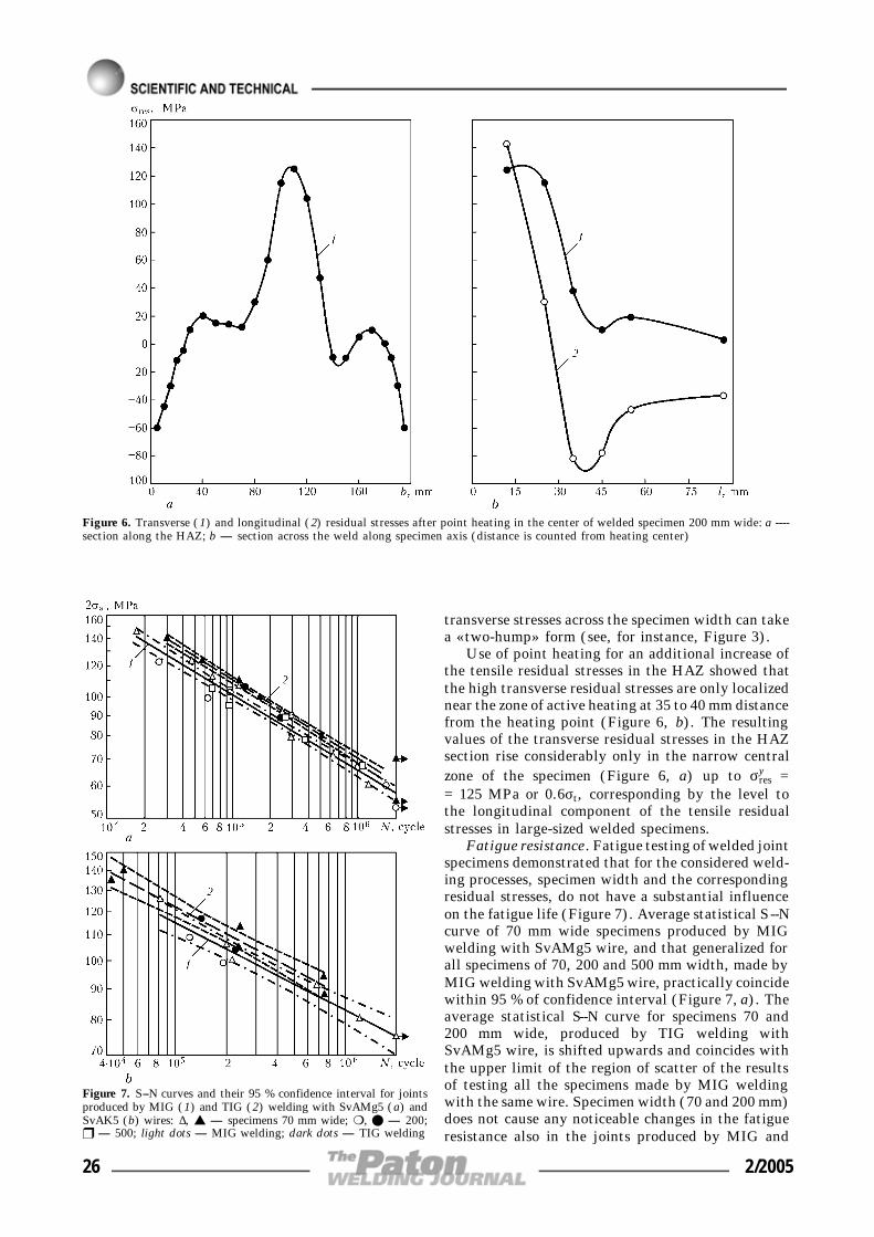
transverse stresses across the specimen width can takea «two-hump» form (see, for instance, Figure 3).
Use of point heating for an additional increase ofthe tensile residual stresses in the HAZ showed thatthe high transverse residual stresses are only localizednear the zone of active heating at 35 to 40 mm distancefrom the heating point (Figure 6, b). The resultingvalues of the transverse residual stresses in the HAZsection rise considerably only in the narrow centralzone of the specimen (Figure 6, a) up to σres
y == 125 MPa or 0.6σt, corresponding by the level tothe longitudinal component of the tensile residualstresses in large-sized welded specimens.
Fatigue resistance. Fatigue testing of welded jointspecimens demonstrated that for the considered weld-ing processes, specimen width and the correspondingresidual stresses, do not have a substantial influenceon the fatigue life (Figure 7). Average statistical S--Ncurve of 70 mm wide specimens produced by MIGwelding with SvAMg5 wire, and that generalized forall specimens of 70, 200 and 500 mm width, made byMIG welding with SvAMg5 wire, practically coincidewithin 95 % of confidence interval (Figure 7, a). Theaverage statistical S--N curve for specimens 70 and200 mm wide, produced by TIG welding withSvAMg5 wire, is shifted upwards and coincides withthe upper limit of the region of scatter of the resultsof testing all the specimens made by MIG weldingwith the same wire. Specimen width (70 and 200 mm)does not cause any noticeable changes in the fatigueresistance also in the joints produced by MIG and
Figure 6. Transverse (1) and longitudinal (2) residual stresses after point heating in the center of welded specimen 200 mm wide: a ----section along the HAZ; b ---- section across the weld along specimen axis (distance is counted from heating center)
Figure 7. S--N curves and their 95 % confidence interval for jointsproduced by MIG (1) and TIG (2) welding with SvAMg5 (a) andSvAK5 (b) wires: ∆, s ---- specimens 70 mm wide; m, l ---- 200;r ---- 500; light dots ---- MIG welding; dark dots ---- TIG welding
26 2/2005
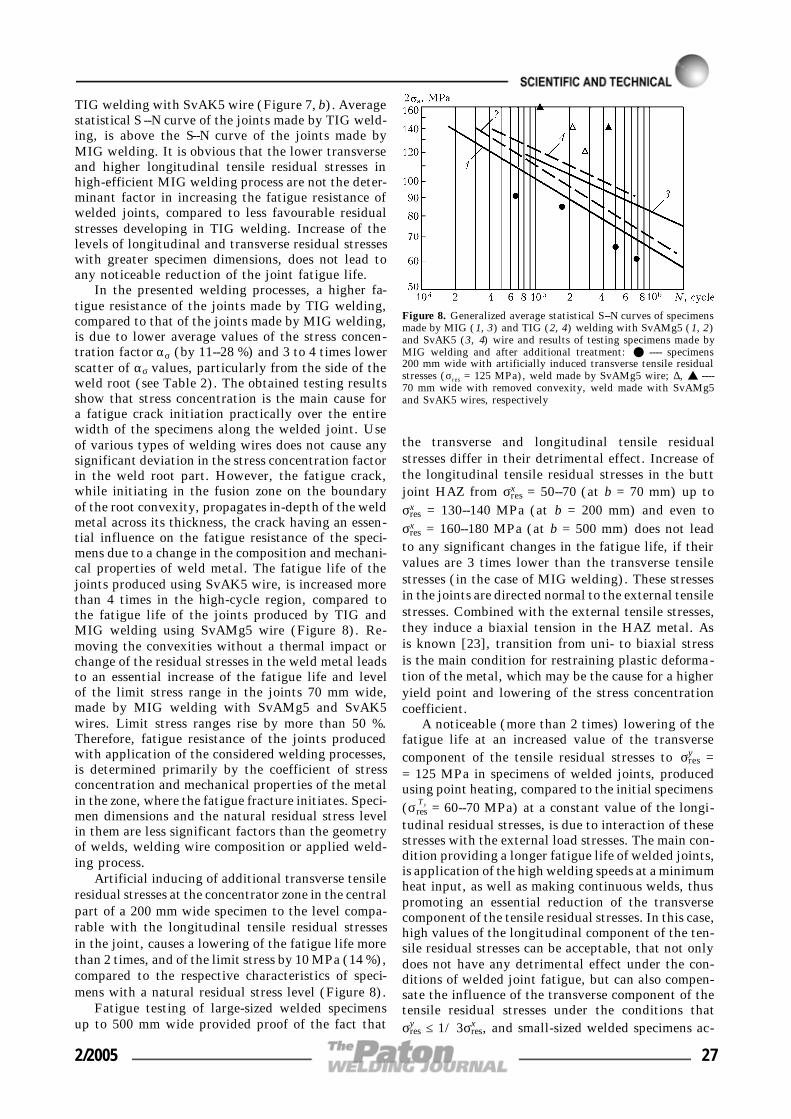
TIG welding with SvAK5 wire (Figure 7, b). Averagestatistical S --N curve of the joints made by TIG weld-ing, is above the S--N curve of the joints made byMIG welding. It is obvious that the lower transverseand higher longitudinal tensile residual stresses inhigh-efficient MIG welding process are not the deter-minant factor in increasing the fatigue resistance ofwelded joints, compared to less favourable residualstresses developing in TIG welding. Increase of thelevels of longitudinal and transverse residual stresseswith greater specimen dimensions, does not lead toany noticeable reduction of the joint fatigue life.
In the presented welding processes, a higher fa-tigue resistance of the joints made by TIG welding,compared to that of the joints made by MIG welding,is due to lower average values of the stress concen-tration factor ασ (by 11--28 %) and 3 to 4 times lowerscatter of ασ values, particularly from the side of theweld root (see Table 2). The obtained testing resultsshow that stress concentration is the main cause fora fatigue crack initiation practically over the entirewidth of the specimens along the welded joint. Useof various types of welding wires does not cause anysignificant deviation in the stress concentration factorin the weld root part. However, the fatigue crack,while initiating in the fusion zone on the boundaryof the root convexity, propagates in-depth of the weldmetal across its thickness, the crack having an essen-tial influence on the fatigue resistance of the speci-mens due to a change in the composition and mechani-cal properties of weld metal. The fatigue life of thejoints produced using SvAK5 wire, is increased morethan 4 times in the high-cycle region, compared tothe fatigue life of the joints produced by TIG andMIG welding using SvAMg5 wire (Figure 8). Re-moving the convexities without a thermal impact orchange of the residual stresses in the weld metal leadsto an essential increase of the fatigue life and levelof the limit stress range in the joints 70 mm wide,made by MIG welding with SvAMg5 and SvAK5wires. Limit stress ranges rise by more than 50 %.Therefore, fatigue resistance of the joints producedwith application of the considered welding processes,is determined primarily by the coefficient of stressconcentration and mechanical properties of the metalin the zone, where the fatigue fracture initiates. Speci-men dimensions and the natural residual stress levelin them are less significant factors than the geometryof welds, welding wire composition or applied weld-ing process.
Artificial inducing of additional transverse tensileresidual stresses at the concentrator zone in the centralpart of a 200 mm wide specimen to the level compa-rable with the longitudinal tensile residual stressesin the joint, causes a lowering of the fatigue life morethan 2 times, and of the limit stress by 10 MPa (14 %),compared to the respective characteristics of speci-mens with a natural residual stress level (Figure 8).
Fatigue testing of large-sized welded specimensup to 500 mm wide provided proof of the fact that
the transverse and longitudinal tensile residualstresses differ in their detrimental effect. Increase ofthe longitudinal tensile residual stresses in the buttjoint HAZ from σres
x = 50--70 (at b = 70 mm) up toσres
x = 130--140 MPa (at b = 200 mm) and even toσres
x = 160--180 MPa (at b = 500 mm) does not leadto any significant changes in the fatigue life, if theirvalues are 3 times lower than the transverse tensilestresses (in the case of MIG welding). These stressesin the joints are directed normal to the external tensilestresses. Combined with the external tensile stresses,they induce a biaxial tension in the HAZ metal. Asis known [23], transition from uni- to biaxial stressis the main condition for restraining plastic deforma-tion of the metal, which may be the cause for a higheryield point and lowering of the stress concentrationcoefficient.
A noticeable (more than 2 times) lowering of thefatigue life at an increased value of the transversecomponent of the tensile residual stresses to σres
y == 125 MPa in specimens of welded joints, producedusing point heating, compared to the initial specimens(σres
Ty = 60--70 MPa) at a constant value of the longi-tudinal residual stresses, is due to interaction of thesestresses with the external load stresses. The main con-dition providing a longer fatigue life of welded joints,is application of the high welding speeds at a minimumheat input, as well as making continuous welds, thuspromoting an essential reduction of the transversecomponent of the tensile residual stresses. In this case,high values of the longitudinal component of the ten-sile residual stresses can be acceptable, that not onlydoes not have any detrimental effect under the con-ditions of welded joint fatigue, but can also compen-sate the influence of the transverse component of thetensile residual stresses under the conditions thatσres
y ≤ 1/3σresx , and small-sized welded specimens ac-
Figure 8. Generalized average statistical S--N curves of specimensmade by MIG (1, 3) and TIG (2, 4) welding with SvAMg5 (1, 2)and SvAK5 (3, 4) wire and results of testing specimens made byMIG welding and after additional treatment: l ---- specimens200 mm wide with artificially induced transverse tensile residualstresses (σres = 125 MPa), weld made by SvAMg5 wire; ∆, s ----70 mm wide with removed convexity, weld made with SvAMg5and SvAK5 wires, respectively
2/2005 27

cepted in practice can be used for conducting fatiguetests.
CONCLUSIONS
1. It is found that application of automated processesof arc welding of butt joints of alloy AD33 T1 6 mmthick on individual specimens 70 to 600 mm widewith a transverse continuous weld promotes develop-ment of tensile residual stresses in the HAZ centralpart with the ratio of the level of longitudinal stressesto transverse stresses of 3:1 (in MIG welding) and1.4:1.0 (in TIG welding). In the case of MIG weldingthe longitudinal tensile stresses reach their maximumstable level (0.8σt) in the HAZ at specimen width ofmore than 300 mm. At the same width of the specimens(b = 200 mm) the transverse tensile residual stressesare 1.8 times lower in MIG welding than in TIGwelding.
2. Under the impact of a cyclic load across theweld section, the role of tensile residual stresses lon-gitudinal and transverse relative to the weld is notidentical at fatigue damage. Increase of longitudinalresidual stresses from 40 up to 160 MPa due to increaseof specimen width in MIG welding practically doesnot detract from the joint fatigue life. However, in-crease of transverse tensile residual stresses from 40up to 125 MPa through additional measures with un-changed level of the longitudinal residual stresses re-duces the fatigue life of the specimens more than 2times.
3. It is not rational to apply large-sized specimensfor conducting fatigue tests of aluminium alloy jointsmade by the MIG processes by a continuous weld, asincrease of the specimen width above 70 mm does notlead to any significant increase of the transverse com-ponent of the tensile residual stresses. There is no needfor additional measures to increase the transverse resid-ual stresses in narrow specimens, as the stress concen-tration, due to the convex shape of the weld, is the maindamaging factor under cyclic load.
1. Trufyakov, V.I. (1973) Fatigue of welded joints. Kiev:Naukova Dumka.
2. Shonin, V.A. (1982) Analysis of results of fatigue tests ofAMg6 alloy welded joints. Avtomatich. Svarka, 3, 71--73.
3. Sanders, W.W., Day, R.H. (1983) Fatigue behavior of alu-minum alloy weldments. WRS Bull., 266.
4. Dvoretskii, V.I., Mikheev, P.P., Shonin, V.A. (1984) Aprocedure of fatigue analysis of aluminum structure weldedjoints. IIW Doc. XIII-1138--84.
5. Kelsy, R.A., Nordmark, G.E. (1984) Effect of residualstresses on fatigue resistance of aluminium alloy butt joints.In: Proc. of Soviet-American Seminar on Welding of Alu-minium Alloys of Cryogenic and General Purposes, Kiev,June 1981. Kiev: Naukova Dumka.
6. Shonin, V.A. (1984) Fatigue resistance of aluminium alloywelded joints taking into account the effect of residualstresses. Syn. of Thesis for Cand. of Techn. Sci. Degree.Kiev.
7. RD 50-551--85. Calculations and strength tests. Computati-onal-experimental methods of evaluation of welded joint fa-tigue resistance: Proc. Guidelines. Moscow: Standart.
8. Shonin, V.A. (1990) Fatigue limit of AMg6 alloy weldedjoints. Avtomatich. Svarka, 4, 12--18.
9. RD 50-694--90. Reliability in engineering. Probabilisticmethod of calculation of welded joint fatigue. In: Proc. Gu-idelines. Moscow: Standart.
10. Kazimirov, A.A., Nedoseka, A.Ya. (1962) About residualstresses and strains arising in welding of AMg5V alloy. Av-tomatich. Svarka, 10, 16--21.
11. Kiselyov, S.N., Khavanov, V.A., Skornyakov, L.M. et al.(1966) Special features of distribution of surface residualstresses in welded plates of avial alloy. Svarochn. Proizvod-stvo, 12, 6--8.
12. Tanaka, E., Hirata, K., Takeuchi, K. (1970) Residual stressin butt-welded 5083 aluminum alloys. Studies on residualstresses in welded joints of aluminum alloys. Light Metals,1, 7--15.
13. Nedoseka, A.Ya. (1974) Residual stresses in plates duringwelding of butt joint. Avtomatich. Svarka, 11, 32--38.
14. Guz, A.N., Makhort, F.G., Gushcha, O.I. et al. (1974)Principles of ultrasonic non-destructive method of stress de-termination in solids. Kiev: Naukova Dumka.
15. Okerblom, N.O. (1950) Welding stresses in metal structu-res. Moscow-Leningrad: Mashgiz.
16. Makhnenko, V.I. (1976) Calculation methods of study ofweld stress and strain kinetics. Kiev: Naukova Dumka.
17. Trufyakov, V.I., Mikheev, P.P., Shonin, V.A. et al. (1976)Effect of residual stresses on fatigue resistance of aluminiumalloy welded joints. Avtomatich. Svarka, 5, 37--39.
18. Shonin, V.A. (1978) Effect of residual stresses on fatigueresistance of load-carrying element of AMg6 alloy in thepoint of welding-up transverse stiffeners. Ibid., 1, 70--71.
19. Mikheev, P.P., Shonin, V.A. (1981) Fatigue resistance ofaluminium alloy welded joints allowing for the stressedstate. In: Proc. of Soviet-American Seminar on Welding ofAluminium Alloys of Cryogenic and General Purposes,Kiev, June 1981. Kiev: Naukova Dumka.
20. Maddox, S.J. (2003) Review of fatigue design rules for wel-ded structures. The Paton Welding J., 10/11, 94--99.
21. Guz, A.N., Makhort, F.G., Gushcha, O.I. (1977) Introduc-tion to acousto-elasticity. Kiev: Naukova Dumka.
22. Makhnenko, V.I., Mosenkis, R.Yu. (1985) Calculation ofcoefficients of stress concentration in welded joints withbutt and fillet welds. Avtomatich. Svarka, 8, 7--18.
23. Osaulenko, L.L., Kotenko, E.V. (1981) Biaxial tension andsensitivity of material to stress concentration. ProblemyProchnosti, 3, 21--25.
28 2/2005
OPTIMIZATION OF PARAMETERSOF DETONATION-GAS SPRAYINGUSING A GENETIC ALGORITHM
V.A. ULSHIN and M.Yu. KHARLAMOVV. Dal East-Ukrainian National University, Lugansk, Ukraine
A method is proposed to determine the optimum process parameters of detonation-gas spraying of coatings by thecriterion of energy characteristics of the spray powder particles, which is based on the use of a genetic algorithm.Advantages of this approach are demonstrated compared to other methods of solving the optimization problems, andcomputer simulation is used to demonstrate its effectiveness.
K e y w o r d s : detonation-gas spraying, simulation, optimiza-tion, particle velocity, particle temperature, genetic algorithm
Conditions of coating formation are strongly affectedby the velocity and temperature of the spray particles.In their turn, the energy characteristics of the particlesat detonation-gas spraying of coatings (DGSC) de-pend on many process parameters. Therefore, in orderto produce coatings with the specified properties, itis necessary to establish the optimum parameters. Thelarge number of these parameters, as well as impos-sibility of separating the process, which determinesthe final results, make search for optimized sprayingconditions more difficult. In practice, conducting agreat variety of expensive experiments solves theproblem of finding the optimum parameters of DGSCprocess. Analytical procedures of finding optimizedspraying conditions do not provide any precise rec-ommendations. These procedures consist either infinding a partial optimum by variation of process fac-tors by one of the possible optimization parameters[1], or a tentative algorithm of process construction(depending on the used particle material), which iseventually also reduced to variation of the some proc-ess parameters with the others being constant [2]. Asa result, when solving a specific problem of producingcoatings with the specified properties, the above meth-ods can only provide estimated values of process pa-rameters, and imply conducting full-scale experi-ments.
This study was aimed at development of themethod of optimizing the process modes of DGSC,allowing for all the parameters, which affect the en-ergy characteristics of the spraying particles, and,thus also the coating formation. These include [1, 3,4] powder composition; gas mixture composition;powder particle size; powder sample; initial arrange-ment of particles in the D-gun (DG) channel; geo-metrical parameters of DG channel; and shooting dis-tance.
Let us consider selection of optimization parame-ters and criteria in greater detail. During calculationsthe geometrical parameters of DG channel and powder
composition were assumed to be preset, and the otherparameters were optimized for a number of causes.Selection of the spray powder composition is mainlydetermined by the operating conditions of the itemto be sprayed, which excludes this parameter fromthe number of the variable ones.
An urgent problem is development of detonationcombustion chambers (DG channels) optimum as totheir design for spraying the coatings. However, inview of the diversity of the possible variants of chan-nel design (use of DG with composite parts, whichchange the shape of longitudinal and transverse sec-tion of the channel, use of various fillers, etc.), thespace of searching for the optimum parameters isgreatly increased, and the problem becomes practi-cally unsolvable.
From the theory of thermal spraying it followsthat the velocity and temperature of the sprayed par-ticles are the determinant parameters in coating for-mation. Space-time distribution of the above valuesin the zone of coating formation has a very importantrole here. On the other hand, the data on the requiredmode of distribution of particle parameters in timeand space to produce coatings with the specified prop-erties, are absent in publications. The cause for thatis insufficient understanding of physico-chemicalprocesses of coating formation in thermal spraying.As a result, when solving specific problems simplifiedmathematical models are applied, which only indi-rectly reflect the structural features of the sprayedcoatings. Therefore, in a number of cases averagedvalues of velocity and temperature of powder particlesat interaction with the sprayed surface can be used.
These characteristics were used also at optimiza-tion of DGSC process in this work. In the future withthe advance of the theory of interaction of a pulsedtwo-phase jet and base at DGSC, the optimizationcriteria can be widened, which will promote selectionof optimum spraying modes, providing coatings withthe specified structure and properties.
Such an optimized parameter as powder particlesize should be considered separately. The known stud-ies on detonation spraying usually consider either the© V.A. ULSHIN and M.Yu. KHARLAMOV, 2005
2/2005 29

dynamics of individual particle behaviour in the flowof detonation products (DP), or a flow of monodis-perse gas suspension. In selection of spraying processparameters, use of the latter approach is preferable,as it allows for such a factor as influence of the powdersample on two-phase flow parameters. In [1, 5, etc.]the dynamics of behaviour of polydisperse flows isstudied, using several simplifications (several clustersof particles of different diameter are considered, theparticles in one cluster having one co-ordinate andvelocity, etc.), this not allowing particle distributionby size to be regarded as a continuous process. Greateraccuracy and validity of simulation results can beachieved at simultaneous description of the dynamicsof behaviour of a large number of particles. This wasdone in [6], where the motion of powder particle ina plasma jet was simulated for 3000 particles. Muchmore time required to solve the problems should beregarded as one of the disadvantages of the modelsdescribing the behaviour of polydisperse powders. Atthe current level of development of computer systems,this is not acceptable for solving the optimizationproblems, requiring calculation of a large number ofpossible variants of the optimized parameter values.For these purposes, it is rational to use mathematicalmodels, describing the behaviour of a monodispersepowder at DGSC, while considering the average par-ticle diameter in the spay fraction.
Thus, the researchers have the task of selectingthe composition of the used gas mixture, average di-ameter of the powder particles, powder sample, initialarrangement of the particles in the DG channel andthe shooting distance at the set geometrical parame-ters of DG channel and powder composition, in orderto give the spray particles the specified values of av-erage velocity and temperature at interaction withthe surface being treated.
In this work a model from [7] was used that allowsdetermination of the space-time parameters of thesprayed particle flow, both inside DG channel, andin the space between the channel edge and the treateditem, also when using DG channels of a variable cross-section. Simulation was conducted under the follow-ing conditions. DG channel of length L, having acylindrical shape of inner diameter d, or a channel ofa variable section, having output diameter d, is par-tially or completely filled with a mixture of gases at
their initial pressure p0, density ρ0 and temperatureT0. A gas suspension of solid spherical particles isinside the channel in region (z1, z2) at 0 ≤ z1 < z2 ≤≤ L. At initiation a stationary detonation wave (DW)forms at the left closed end of the channel, whichpropagates to the right at detonation velocity D (Fi-gure 1). At partial filling of the channel by a deto-nation mixture, unreacted gas takes up the remainingpart of the channel. In this case, after DW has reachedthe contact boundary of gas mixture--unreacted gas(GM--UG), DW decomposes into a shock wave mov-ing along UG and rarefaction wave moving in theopposite direction through DP. After the shock ordetonation wave has reached the open end of the chan-nel, DP and disperse particles start outflowing intothe surrounding gas atmosphere.
Boundary conditions were defined as follows. Con-ditions of non-flowing of the gas and disperse particleswere assumed on the axis of symmetry and walls ofDG channel. As long as DW has not reached GM--UGcontact boundary, its parameters are found by theformulas for the front of the stationary DW (rightboundary condition). After DW has reached the con-tact boundary, conditions of free flow of the phasesare set on the open boundaries of calculation regionAB and BC, and the condition of non-flow for thegas phase and free penetration for the disperse phaseis specified on right boundary CE according to [8],i.e. the powder which has reached the barrier, issprayed on it.
The following assumptions were used: pressure isonly induced by gas; influence of powder particles isignored; viscosity and heat conductivity of the phasesis only taken into account in the processes of inter-phase interaction; distances over which the flow pa-rameters change, are much greater than the dimen-sions of the particles or distances between them; par-ticles are spherical monodisperse ones and do not reactwith DP; fragmentation or collision of particles areabsent; before the start of the flow DP are consideredas the reacting medium, having an equilibrium com-position in each point, and after the outflow start ----as an inert gas with a costant adiabatic index; particleinfluence on DW characteristics is ignored.
A system of equations of a two-dimensional axi-symmetric nonstationary motion of the gas suspensionhas the following form [9]:
Figure 1. Schematic of a DG channel and design area (for designations see the text)
30 2/2005

∂ρi
∂t + 1r ∂(rρivi)
∂r + ∂(ρiui)
∂z = 0;
∂(ρivi)∂t +
1r ∂(rρivi
2)∂r +
∂(ρiviui)∂z + αi
∂p∂r
= (--1)ifr n,
∂(ρiui)∂t +
1r ∂(rρiviui)
∂r + ∂(ρiui
2)∂z + αi
∂p∂r
= (--1)ifz n,
∂(ρ2e2)∂t +
1r ∂(rρ2e2v2)
∂r + ∂(ρ2e2u2)
∂z = qn,
∑i = 1
2
[∂(ρiEi)
∂t + 1r ∂(rρiviEi)
∂r + 1r ∂(rαipvi)
∂r +
+ ∂(ρiuiEi)
∂z + ∂(αipui)
∂z ] = 0;
ρi = αiρi0, Ei = ei + (vi
2 + ui2) ⁄ 2,
n = 6α2 ⁄ (πδ3), α1 + α2 = 1, ρ20 = const, i = 1, 2,
where vi and ui are the velocity components in radialr and axial z directions, respectively; ei, Ei are thespecific internal and full energy of i-th phase; p isthe gas pressure; fz, fr are the components of forceinteraction from the side of the gas on the disperseparticle in cylindrical co-ordinates; q is the intensityof heat input into the individual particle surface; nis the number of disperse particles in a unit of mixturevolume. Share of mixture volume taken up by i-thphase, is characterized by its bulk content αi. Eachpoint of mixture volume is correlated with averagephase density ρi, characterizing phase mass in a unitof volume, and true phase density ρi
0, characterizingthe density of substances, making up the mixture.Indices i = 1 are for the gas; and i = 2 are for dispersephases.
Equations of state of an ideal gas were used ----p = ρ1
0RT1/µ1, e1 = e1(T1), where R is the absolutegas constant; µ1 is the DP molecular mass; T1 is thegas phase temperature. Equation of the total innerenergy of the gas e1(T1, µ1) and equation of chemicalequilibrium µ1(ρ1, T1) [10, 11] were used for thereacting gas flow before the outflow start. Equationfor the inner energy of the disperse phase, having theform e2 = e2(T2), where T2 is the disperse phase tem-perature, was written, allowing for the possible phasetransition (particle melting).
Assigning the laws of interphase force and thermalinteraction of the gas and disperse phases fz, fr, q,closed derived system of equations. Numerical inte-gration was performed by the method of «coarse par-ticles» [8]. The difference scheme was constructedallowing for conducting the calculations for DG chan-nels of a variable cross-section.
DW parameters required for calculations (deto-nation velocity, temperature, pressure, density, gasvelocity in Champen--Juge point, etc.), were calcu-lated for a mixture with the conditional formulaCaHbOcNd with addition of inert gases based on bal-ance equations of material, chemical equilibrium, gasdynamics and equation of state, using the model of[12].
In order to solve the optimization problem, one ofthe representatives of the class of evolutional methodsof calculation, namely a genetic algorithm (GA), wasselected [13, 14]. Application of this algorithm allowsgeneration of efficient algorithms for a broad class ofoptimization problems [15]. This does not require anyadditional information on the nature of the studiedfunction, its properties (differentiability, continuity,etc.), and no restrictions are applied to the searchregion, which may be non-convex or multiply con-nected. Features of other methods of solving theglobal optimization problems, the main of which arethe enumeration and local-gradient approaches, donot allow their use in optimization of DGSC processmodes. Enumeration algorithm is the simplest to im-plement, but searching for an optimum solution re-quires calculation of all the possible variants of vari-able values, which is unrealistic for multiparametricmultiextremal problems. Gradient methods are veryfast, but do not ensure the optimality of the derivedsolution. They are ideal for solving the problems,where the criterion function has one extremum. Interms of the speed and accuracy of calculation GA issuperior also to random search methods (Monte-Carlomethod, etc.), as it allows accumulating successfulsolutions during the calculation process.
The main idea of a GA consists in a collectivesearch for an optimum through a multitude of inde-pendent sets of values (vectors) of variables, whichare the potential solutions. At the initial stage, thevariable vectors are generated in a random manner.Furtheron, each new multitude of sets of variablevalues is formed on the basis of the previous one bycertain rules, taking into account the criterion func-tion. During iterating, the criterion function valueaverage over the set, verges towards the extremum.GA usually uses the terminology taken from biology.So one combination of a set of variable values is anindividual, and a set of individuals for each iterationof the algorithm, is a population. Individual adapta-tion is a quantitative characteristic, showing how suc-cessful is the individual in solving the posed problem,i.e. adaptation is the value of criterion function fora given variant of variable set. Let us consider GAfunctioning in greater detail for the case of optimiza-tion of DGSC process parameters.
In GA the variable vectors are coded into a chro-mosome, which is a chain of symbols written usingtwo, three or four letters of the alphabet. In the al-gorithm version for establishing the optimum parame-ters of DGSC process, a binary coding variant wasused, which is the most natural in the algorithm im-plementation on a computer, where all the informa-tion is a sequence of zeros and units. In addition, thisversion demonstrated faster convergence at algorithmtesting. Each variable is coded by a certain fragmentof the chromosome, consisting of a fixed number ofgenes (digits). Adjacent fragments are not separatedfrom each other in any way, but at backward decodingof the chromosome into a variable vector one and the
2/2005 31

same mapping mask is used over the entire simulationperiod. Chromosome dimension is determined pro-ceeding from the number of optimization parametersand bit number, required for each parameter coding.The interval of possible values of parameter ki[ai, bi]and accuracy of its discrete variation εi, are taken intoaccount. Allowing for the set conditions, bit numberki, required for coding ki is found from relationship:
ti = ln
bi -- ai
εi + 1
ln 2.
As an example, Figure 2 shows chromosome map-ping for the most often used in DGSC gas mixture ofacetylene, oxygen and nitrogen and aluminium pow-der.
The direct operation of variable vector coding intoa chromosome is not used in GA. The chromosomesare generated at random, all subsequent populationchanges affect the genetic level first, and only afterthat the chromosomes are decoded and consequencesof these changes are analyzed.
During calculations the new population is pro-duced by acting on the genotype of the parent indi-viduals of genetic operators: crossover, mutation andinversion, the action of which is described in detail
in [14]. To produce a new chromosome, crossoveroperator performs exchange of parts into which twoparent chromosomes are divided in any point. Muta-tion operator randomly reverses the state of chromo-some genes. Inversion disturbs the gene sequence inthe offspring chromosome, compared to the parentchromosome. When searching for a global extremum,the most significant is the crossover operator, as itallows selection of variables, corresponding to themost suitable solution variant for the specified crite-rion function (unsuitable variants will not be includedinto the new generation). Inversion operator is alsodesigned for global search, while mutation is identi-fied with the means of local adjustment of the solu-tion.
GA assumes that the number of individuals re-mains unchanged from generation to generation. Un-der such conditions, selection of parent individualsfor producing a new population is important. There-fore, the probability of any individual in the currentpopulation becoming a parent individual is deter-mined in proportion to its adaptation.
At optimization of DGSC process, individual ad-aptation was determined as follows. Process parame-ters, produced at chromosome decoding, were used tomodel the movement of a two-phase flow in DG chan-nel, its outflow into the surrounding gas atmosphere,and average values of velocity Ui and temperature Ti
of particles on the substrate are calculated. If dataon the average values of particle velocity and tem-perature at interaction with the sprayed surface areavailable, the individual can be conveniently repre-sented as a point in the criteria space with axes Uand T (Figure 3). Then adaptation µi(t) of individualAi can be defined as the distance between this indi-vidual parameters and the optimum parameters forproducing the specified coating, and the optimum val-ues of velocity Uopt and temperature Topt can be cal-culated by the following formula:
µi(t) = √(Topt -- Ti)2 + (Uopt -- Ui)
2 → min,
where t is the generation number.After determination of the adaptation of all the
individuals in the population, the average adaptation
for the population µ̂(t) = ∑i = 1
M
µi(t)/M is found, where M
is the number of individuals in the population. Parentindividuals are selected from the individuals with ra-
Figure 2. Example of a chromosome mapping mask
Figure 3. Criteria space for the problem of finding the optimumDGSC process parameters
32 2/2005

tio µ1(t)/µ(t) < 1 with probabilities in proportionto their adaptation.
Algorithm of searching for optimum process pa-rameters of DGSC is shown in Figure 4. Genetic op-erators, namely crossover, inversion, mutation andcopying procedure (when the individual was trans-ferred to the next generation unchanged) were se-lected at each stage at random with probabilities of0.75, 0.05, 0.15, 0.05, respectively. GA functioningwas tested when searching for a minimum of Rosen-brok function.
The results of a numeric experiment on determi-nation of optimum parameters of DGSC process foraluminium oxide powder and gas mixture of acety-lene, oxygen and nitrogen are given below to illustratethe application of the above algorithm. Initial condi-tions were as follows: DG channel 1.6 m long and0.24 m in diameter; C 2H2 volume fraction was selectedto be equal to 1; volume fraction of O 2 1.0--2.5; volumefraction of N2 0--1; possible particle diameter 20--90 µm; powder sample 0.05--1.00 g; possible position
Figure 4. Block-diagram of genetic algorithm functioning
Figure 5. Search for optimum process parameters of DGSC ofcoatings for aluminium oxide particles: a ---- generation numbert = 0; b ---- 4; m ---- 16; l ---- 25
2/2005 33
of left boundary of powder cloud 0.8--1.2 m; rightone 1.1--1.6 m from the closed end of DG channel;shooting distance 0.10--0.25 m. Velocity U == 850 m/s and temperature T = 2500 K were selectedas the optimum particle parameters. Population con-sisted of 30 individuals. Searching for optimum proc-ess parameters is shown in Figure 5.
As is seen from Figure 5, GA converges ratherquickly, and by 25th generation all the individuals aregrouped around the extremum. The following parame-ters were obtained: gas mixture C2H2 + 1.7O2 ++ 0.88N2; particle diameter 20 µm; powder sample0.05 g; left boundary of powder cloud 0.8 m from theclosed end of DG channel; right boundary 1.28 m; shoot-ing distance 0.1 m. Calculation time in a PC with Pen-tium 4 processor was equal to approximately 1 h.
Thus, software developed on the basis of a geneticalgorithm, essentially simplifies machine experimentson optimization of DGSC process parameters andshortens the time required. This is achieved by com-plete automation of the process of searching for op-timum solutions, so that operator actions are reducedto just entering the initial conditions. Further on thisprogram will be integrated into a system of supportingdecision taking, when designing DGSC technologies.
1. Bartenev, S.S., Fedko, Yu.P., Grigorov, A.I. (1982) Deto-nation coatings in machine-building. Leningrad: Mashino-stroenie.
2. Boguslaev, V.A., Dolmatov, A.I., Zhemanyuk, P.D. et al.(1996) Detonation coating deposition on parts of aircraft
engines and process fixtures with magneto-abrasive post-treatment. Zaporozhie: Deka.
3. Shorshorov, M.Kh., Kharlamov, Yu.A. (1978) Physico-chemical principles of detonation-gas spraying of coatings.Moscow: Nauka.
4. Zverev, A.I., Sharivker, S.Yu., Astakhov, E.A. (1979)Detonation spraying of coatings. Leningrad: Sudostroenie.
5. Karamysheva, S.A., Prokhorov, E.S. (1986) Influence ofthe shape and degree of channel filling by explosive mixtureon parameters of particle acceleration in detonation sprayingunits. In: Transact. on Problems of Detonation Applicationin Technological Processes. Novosibirsk: IGSO AN SSSR.
6. Lugscheider, E., Papenfub-Janzen, N. (2002) Simulation ofthe influence of spray parameters on particle properties inAPS. In: Proc. of ITSC’2002, Essen.
7. Kharlamov, M.Yu. (2003) Dynamics of acceleration and he-ating of powder by detonation-gas jet. In: Transact. on Re-source-Saving Technologies for Manufacturing and Pressu-re Treatment of Materials in Machine-Building. Part 1.Lugansk: V. Dal SNU.
8. Belotserkovsky, O.M., Davydov, Yu.M. (1982) Method ofcoarse particles in gas dynamics. Moscow: Nauka.
9. Nigmatulin, R.I. (1978) Principles of mechanics of hetero-geneous media. Moscow: Nauka.
10. Zhdan, S.A., Fedenyuk, V.I. (1982) Parameters of equilib-rium gas flow in the detonation unit channel. Fizika Gore-niya i Vzryva, 6, 103--107.
11. Nikolaev, Yu.A. (1978) Model of kinetics of chemical reac-tions at high temperatures. Ibid., 4, 73--76.
12. Kharlamov, M.Yu. (2002) Calculation of product composi-tion and parameters of gas mixture detonation in sprayingof coatings. Visnyk V. Dal SNU, 11, 254--262.
13. Kruglov, V.V., Borisov, V.V. (2002) Artificial neural net-works. Theory and practice. Moscow: Gor. Liniya--Telecom.
14. Voronovsky, G.K., Makhotilo, K.V., Petrashev, S.N. et al.(1997) Genetic algorithms, artificial neural networks andproblems of virtual reality. Kharkov: Osnova.
15. Batishchev, D.I., Isaev, S.A. (1997) Optimisation of mul-tiextremal functions using genetic algorithms. In: Transact.on High Technologies in Engineering, Medicine and Edu-cation. Voronezh: VGTU.
34 2/2005

FUSION WELDING OF TITANIUM AND ITS ALLOYS(REVIEW)
V.E. BLASHCHUK1 and G.M. SHELENKOV2
1E.O. Paton Electric Welding Institute, NASU, Kiev, Ukraine2Open Joint Stock Company «M.V. Frunze Sumy Research and Production Machine-Building Factory», Sumy, Ukraine
Practical applications of different methods for fusion welding of titanium and its alloys are reviewed. Recommendationson the use of these welding methods are given, and their advantages and disadvantages are considered.
K e y w o r d s : beam welding methods, metal- and tungsten-arc welding in shielding gases and vacuum, submerged-arc me-tal-electrode welding, electroslag welding, plasma arc and mic-roplasma welding, titanium, titanium alloys, technological ca-pabilities, base metal thickness
Titanium and its alloys are characterised by specialphysical-mechanical properties, such as high specificstrength and corrosion resistance under atmosphericconditions, in sea water and in a number of aggressiveenvironments, where many traditional materials ex-hibit low or insufficient strength [1].
The scopes of commercial application of titaniumand its alloys depend in many respects upon the tech-nological capabilities of a welding process. Substan-tial difficulties in welding of titanium arise, first ofall, because of its high reactivity at increased tem-peratures. Titanium alloys lose ductility and acquiresensitivity to delayed fracture as a result of interactionwith atmospheric gases. Defects (e.g. pores) areformed in the welds, resulting in a considerable de-crease in fatigue resistance and leading to fracture ofa welded structure. Welding of thermally unstablealloys is hampered by peculiar structural changes andphase transformations in the weld and HAZ metalduring the thermal-deformation welding cycle, whichmay lead to formation of brittle and unstable phases.However, selection of appropriate welding methodsand utilisation of optimal conditions of welding andpostweld heat treatment can help to provide soundwelded joints.
The majority of the existing fusion welding meth-ods (except for manual arc welding using stick elec-trodes) are applied now for joining titanium and ti-tanium alloys [1--7].
The purpose of this study is to systematise infor-mation on technological capabilities of processes forfusion welding of titanium and its alloys of differentthickness.
The main difficulty arising in fusion welding oftitanium is to ensure reliable protection of the weldpool, weld root and cooling regions of the weldedjoints from contact with air.
Regions of a welded joint heated to a temperatureabove which a marked interaction of titanium withatmospheric gases begins require shielding. As indi-
cated in home literature and standards, this tempera-ture is equal to 400 °C [2--4], while according to theAWS standards it is equal to 500 °F (250 °C) [7].Vacuum and inert gases, such as argon, helium andtheir mixtures, are used for shielding. As the qualityof the welded joint depends upon the purity of inertgas, argon of the first (volume content of argon isnot less than 99.987 %) and highest grade (GOST10157--79), as well as high-purity helium (TU 51-940--80) are used for shielding. In western countriesargon (EN439, class 11) and helium (EN439,class 12), as well as their mixtures (EN439, class 13)are used, according to EN439:1994. Selection of ashielding gas is based on ANSI/AWS C5.6-94R [7].
The following versions of shielding of the weldingzone with an inert gas are used, depending upon thesizes of parts welded and requirements to their qual-ity:
• general shielding of a part in chamber with acontrollable atmosphere. This is the case of the mostreliable shielding of the welding zone and coolingregions of the weld, its root and HAZ. It is reasonableto use this type of shielding in mass production andmanufacture of parts of complex configuration;
• local shielding of a welded joint using local microchambers, which finds application primarily in weld-ing of circumferential position and roll butt joints.In this case the back side of the weld is shieldedthrough filling the workpiece cavity with an inertgas;
• jet-type shielding of the welding zone and cool-ing regions of the joint, provided through their con-tinuous blowing using a nozzle with a larger orificediameter and longer extension, compared with weld-ing other metals and alloys. Blowing of the weld rootis provided using an additional device, which feedsinert gas from below [2--9]. Therefore, in this casethe shielding gas is fed into three channels: into anozzle and shielding devices, i.e. elongated extensionand forming protective backing.
Welding of titanium alloys in vacuum is performedunder a pressure of residual gases equal to 1⋅10--2 Pa.Welding in low (about 1--10 Pa) vacuum also findsapplication. This atmosphere is much cleaner as tothe oxygen and nitrogen content than argon of class 1.Welding in vacuum eliminates any contamination of© V.E. BLASHCHUK and G.M. SHELENKOV, 2005
2/2005 35
metal of the welded joints with harmful impurities(gases) and provides ductility and toughness of thewelded joints as close as possible to those of the basemetal (BM) [3--5, 8].
Quality of the titanium welded joints is deter-mined in many respects by the technology used forpreparation of edges for welding, as well as by thegrade of a titanium welding wire. Preparation of edgesfor welding is performed only by machining. Rough-ness of the edge surfaces should be not worse thanRz = 40 (GOST 2789). The surfaces of parts adjoiningthe edges on both sides at a distance of not less than20 mm are cleaned with a scraper or electrocorundumwheel, or with a rotating metal brush or vulcanitewheel. No overheating of metal is permitted in clean-ing with abrasive wheels, as it causes formation oftemper colours on the welded joint surfaces. Imme-diately before tack welding and welding, the cleanedsurfaces of the welded joint and welding wire aredegreased, and then moisture is removed using a cleancotton cloth wetted with acetone or commercial ethylalcohol.
Arc welding methods have received the widest ac-ceptance for welding titanium. Among them the mostwidespread method is tungsten-electrode inert-gas(TIG) welding. This welding method is most versa-tile, as it allows a joint to be welded in differentspatial positions and under restrained conditions, andrequires no re-adjustment of equipment when thick-ness of a metal welded or type of a joint is changed.
TIG welding is performed at direct current ofstraight polarity. The tungsten electrode is a cathode,and its life, shape of a pointed tip and constancy ofemissive ability determine in many respects the weld-ing process stability, quality of weld formation andpenetration depth. The Table gives data on correspon-dence of tungsten electrodes to a number of nationaland international standards. Electrodes of pure (un-alloyed) tungsten are not applied for welding tita-nium, as they are characterised by an insufficient life[3, 4, 7]. Diameter of a non-consumable electrode isselected depending upon the amperage, allowing fora permissible current load.
Automatic, mechanised and manual welding canbe performed using a continuous or pulsed arc. Platesof titanium alloys with thickness b ≤ 5 mm can bejoined in single pass by TIG welding using the surfacearc without groove preparation (maximal weldingcurrent Iw ≤ 500 A). Titanium butt joints of largethickness are made by multipass welding with groove
preparation or with a narrow gap using filler wire.Titanium welding wires are used as filler materialsfor welding titanium and its alloys. Composition ofa welding wire depends upon the type of the materialsjoined and postweld heat treatment of the weldments[1--4, 7].
Pulsed-arc TIG welding using straight polaritycurrent pulses is used to join sheets 0.5--2.0 mm thick.Size of the weld can be changed through regulatingthe welding current and speed, as well as duration ofthe current pulses and pauses. With this weldingmethod the level of deformation of titanium structuresis 15--30 % lower than in welding using the continuousarc, the level of residual stresses and sensitivity ofthe welds to porosity, which is the main defect inwelding using the surface arc, are decreased. In ad-dition, the HAZ and crystalline grains are decreasedin size, which leads to improvement of mechanicalproperties of the welded joints [3, 4].
Some improvements in the TIG welding methodwere made to increase the penetrating power of thearc. The following modifications of TIG welding areavailable for joining titanium and its alloys: immersedarc welding with or without electromagnetic stirringof the weld pool, welding with through penetration,welding over the flux layer, welding using flux-coredfiller wire, narrow-gap (slot) welding, twin-arc weld-ing, etc. [2--12].
In immersed-arc welding the tungsten electrodetip is located below the surface of the metal welded.This leads to a substantial rise in the efficiency ofutilisation of thermal power of the arc and allowsmetal plates with b ≤ 15 mm to be welded in one passwithout groove preparation. In the case of two-sidedwelding the titanium plates with thickness b ≤ 36 mmcan be welded by this method. The welds on each sideof a plate are made in two passes without filler wire:the first pass is made by the immersed arc to ensurethe required penetration depth, and the second passis made by the surface arc to smooth the weld andimpart it the required geometric sizes.
The arc is immersed manually (at small thicknessof the metal plates ---- b ≈ 8--10 mm) or using a specialforcing automatic system that controls the arc voltage.The drawbacks of this method include large width ofthe weld and coarse-crystalline structure of the weldmetal, as well as impossibility to regulate chemicalcomposition of metal and high sensitivity to porosity(Figure 1) [2--4, 10].
In immersed-arc welding the controlled move-ments of molten metal in the pool, excited by theaxial magnetic field, provide the possibility of ration-ally affecting the thermal-concentration processesthat determine the solidification processes. This leadsto improvement of structure of the weld metal anddramatic decrease in its porosity [2--3, 11].
Twin-arc welding, where the arcs are burning attungsten electrodes in the axial magnetic field, allowsa 1.5--2 times increase in the permissible speed of thewelding process without the risk of formation of such
Correspondence of tungsten electrodes to standards
ISO 6848EN26848NF
EN26848JIS Z3233
AWS A5.12--98
ANSI/AWSA5.12
Types oftungstenelectrodes
GOST23949--80
Nominalcontent ofactivatingaddition
WC20 EWCe-2 R 07932 ---- 2 % CeO2
WL10 EWLa-1 R 07941 EVL 1 % La2O3
WT20 EWTh-2 R 07912 EVT-12 2 % ThO2
36 2/2005

specific defects of the welds that accompany the forcedconditions as elongated gas cavities. Electromagneticstirring of the weld pool brings the level of mechanicalproperties and electrochemical characteristics of awelded joint close to those of BM, and favours de-crease in defectiveness of the welds, porosity in par-ticular [2--3, 11].
Welding with two tungsten electrodes located inplane normal to the weld axis was developed to in-crease the deposition efficiency in multilayer one-sided TIG welding of titanium plates b ≤ 50 mm thickwith groove preparation. Welding of metal plates b == 50 mm thick by this method is performed in 6--8passes using filler wire with diameter Dw = 5--7 mm.This method is applied in the cases where the weldmetal differs in composition from the base metal, aswell as for cladding. The resulting welded joints arecharacterised by high quality (Figure 2). This weldingmethod and the equipment used to implement it weredeveloped by the E.O. Paton Electric Welding Insti-tute [3--5, 12].
TIG welding with through penetration allows met-al plates with b ≤ 12 mm to be welded in one pass,the set arc length being 0.5--1.0 mm. To provide the«keyhole» type penetration, the welding parametersare set so that a hole is formed in metal beneath thearc, and as the arc advances this hole is filled withliquid metal. To form the weld reinforcement withthis welding method, it is necessary to make the sec-ond pass using a filler wire. However, application ofthis welding process is limited by difficulties associ-ated with regulation of chemical composition of theweld metal over the entire weld section [3, 4].
Argon-arc welding over the flux layer (A-TIG) isan efficient method for affecting the penetratingpower of the arc, as well as the weld formation andweld metal structure. With this welding method hal-ides of alkali and alkali-earth metals leading to achange in character of metal penetration and weldformation through arc contraction are added to thearc atmosphere. A-TIG welding over the flux layerdeposited on the surfaces of the weld edges allowsthe one-pass welds to be made without groove prepa-ration on titanium plates with b ≤ 6--7 mm. In thiscase the current and heat input required for weldingcan be substantially decreased owing to an increasedconcentration of thermal energy in the anode spot.Flux leads not only to increase in the penetrationdepth, but also to change in the penetration shape.Width of the back bead in A-TIG welding grows fasterwith increase in the welding current than width ofthe weld. Conditions of the back bead formation areimproved, and the probability of burns-through inwelding without backing is reduced [3--5].
Low heat input and small width of the weld andHAZ allow application of A-TIG welding not onlyfor making butt joints, but also fillet, T-, overlap,plug and other types of joints in titanium plates withb ≤ 3 mm, which are hard or impossible to weld with-out the application of flux. Welding of overlap and
plug joints can be done either with through or incom-plete penetration of the lower plate. Small volume ofthe weld pool makes it possible to employ A-TIGwelding for making welds in different spatial positionson a vertical plane in titanium plates with b ≤ 6 mm.Distortion of welded structures is reduced by 15--20 %, and porosity is eliminated as a result of theapplication of fluxes. This welding method is espe-cially suitable for joining heat-hardenable and highalloys. However, A-TIG welding requires an increasedaccuracy of fit-up for welding, compared with TIGwelding. Special fluxes of the ANT-A and FAN-1grades were developed for this welding method [3--5].
To feed the required amount of the flux in weldingtitanium plates with b > 4--5 mm, it is added to thearc from the core of a flux-cored filler wire with atitanium sheath. This makes it possible to performone-pass welding of titanium plates with b ≤ 16 mm.A layer of solidified slag, which provides additionalshielding for the cooling metal, remains on the weldsurface after A-TIG welding and welding using flux-cored filler wire. It should be removed by machiningor by a chemical method, which adds to labour con-sumption in welding operations.
Narrow-gap welding is employed to join titaniumplates of medium and large thickness. This weldingmethod allows the volume of deposited metal to bedecreased by about 30 %, the process productivity tobe raised and labour consumption in performing op-
Figure 1. Macrosection of butt welded joint 24 mm thick made byimmersed-arc welding
Figure 2. Macrosection of butt welded joint 30 mm thick made bytwin-arc welding using a filler
2/2005 37

erations associated with edge preparation for weldingto be reduced. The torch with a special device pro-viding welding in reversible axial magnetic field (Fi-gure 3) is used to ensure reliable fusion of the weldmetal with the groove walls in manual tungsten-elec-trode welding [1--3, 11, 13].
The method of automatic narrow-gap magneti-cally-impelled arc tungsten-electrode welding is ap-plied to weld metal plates with b ≤ 110 mm. Thiswelding method allows reduction in utilisation ofwelding consumables, 1.5--2 times increase in processproductivity and decrease in defectiveness of weldedjoints in titanium alloys [3, 4, 13, 14]. This weldingmethod provides the weld metal with a homogeneousstructure and welded joints with high values of me-chanical and corrosion properties.
TIG welding with the surface arc is applied forposition and roll but welding of pipes and welding
of tubes to tube plates. In this case the use is madeof a specialised equipment, which cannot be employedwith other welding methods. These processes are con-sidered in more details in studies [2--4, 7, 15--17].
The E.O. Paton Electric Welding Institute devel-oped and manufactured a range of specialised equip-ment with captive protective micro chambers, inwhich the required purity of inert gases is achievedowing to argon purging. This equipment is intendedfor position butt welding of titanium pipes 10 to200 mm in diameter (b = 0.5--2.0 mm) under fieldconditions. Such chambers are located around a mill,the tungsten electrode is moved using an electric mo-tor, which is set both at a distance from a chamberand in one unit with it. Welding can be performedin a continuous or pulsed mode. Figure 4 shows thegeneral view of a modern welding micro chamber madeas one unit with the electric motor.
TIG welding of tubes to tube plates in heat ex-changers of titanium alloys can be performed in twopositions, i.e. in flat position and on a vertical plane.A deep shaft for vertical location of a heat exchangeris arranged in a workshop to perform flat welding.With this welding method a tube plate is located ina horizontal plane. At the absence of shafts, the tubeplate is placed on a vertical plane and tubes are placedon a horizontal plane. The appropriate welding meth-ods, i.e. manual or automatic TIG welding, are ap-plied depending upon the size of heat exchangers andspatial location of the welds. These operations areperformed by using special equipment of a domestic(Open Joints Stock Company «M.V. Frunze SumyResearch and Production Machine-Building Factory»in Sumy, Ukraine) or foreign production (ESAB,Sweden; Astro Arc Polysoude, France; etc.) [15--18].
Along with TIG welding, also plasma (PW) andmicroplasma (MPW) welding performed in inertgases are applied for making permanent joints in ti-tanium and its alloys. These processes are intendedfor welding titanium plates with thickness b ≤≤ 1.5 mm. The shielding methods used in these casesare similar to those used with TIG welding. PW is ahigh-speed and high-productivity process. It is per-formed with the constricted arc of a cylindrical shape,which is formed through its constriction by the nozzlewalls. The PW equipment is of the following types:for welding titanium plates (b ≤ 4 mm) at a high orlow current, and for metal-electrode welding with thearc burning in the plasma flow [1--4, 19--21].
The constricted transferred arc burning betweenthe electrode and workpiece is used as a heat sourcefor MPW of titanium. A stable arc burning and spatialconsistency of microplasma at low currents (Iw ≥≥ 0.1 A) are achieved owing to a high degree of con-striction of the arc column, which is provided by usinga nozzle with a small-diameter (up to 1 mm) channeland pilot arc continuously burning from the secondpower source. MPW of titanium is performed at adirect current of straight polarity using the arc burn-ing in a continuous or pulsed mode. Argon is used as
Figure 3. Macrosection of butt welded joint 24 mm thick made bymanual narrow-gap welding in axial magnetic field
Figure 4. Chamber with built-in electric motor to drive tungstenelectrode under field conditions (manufactured by Arc Machines,USA)
38 2/2005

a plasma gas, and helium or Ar + (50--70 %) He mix-ture is used as a shielding gas. The mean workinglength of the arc in MPW is almost by an order ofmagnitude larger than in tungsten-electrode weldingin argon. Therefore, comparatively large deviationsof the arc length from an assigned value are permittedwith this welding method, as this has no substantialeffect on the weld parameters. In a case of weldingtitanium parts with b ≤ 0.3 mm, the joints are madeby flanging the edges, and at b = 0.1--0.2 mm theworkpieces are assembled for welding using precisiondevices. Butt joints can be made with or withoutbacking. The E.O. Paton Electric Welding Institutedeveloped corresponding designs of plasmatrons andpower supplies. Mechanical properties of the MPWjoints are practically identical to those of BM. Anyingress of tungsten to the weld is eliminated with thiswelding method.
PW provides deeper penetration than TIG weld-ing. Therefore, PW of parts with b > 10 mm can beperformed without groove preparation. In a case ofPW of thick plates of titanium with the «keyhole»type penetration, the maximal thickness of the plateswelded by the one-pass method is determined primar-ily by width of the back bead, the formation of whichis affected by surface tension forces. Filler wire canbe fed to the leading part of the weld pool. In thiscase the requirements to its diameter and feed speedare as stringent as in TIG welding. The groove in thiscase is one- or two-sided V-shaped. The use of a fillerwire widens the range of welding parameters (gap,edge displacement, welding speed), and it is possibleto control chemical and structural composition of theweld metal, thus preventing the formation of cracks,undercuts, pores and enabling a substantial increasein volume of the deposited metal.
The special heat source for welding processes wasdeveloped to combine advantages of vacuum shieldingand technological merits of TIG welding. This sourceprovides an arc discharge between the tungsten ortitanium hollow non-consumable cathode (ADHC)and a workpiece in vacuum, and it is inferior in energyparameters only to the beam energy sources. Argonis fed at a low flow rate through the hollow cathodeduring welding. Realisation of this process is 3--5times less expensive, compared with the beam weldingprocesses, due to a low cost of equipment and lessstringent requirements to edge preparation and safetymeasures (corresponding to the level of safety in arcwelding performed in a controlled atmosphere). Arcwelding in vacuum allows joining of titanium partswith b = 8--12 mm without groove preparation in onepass without backing in the through penetration modewith a smooth transition to BM on the face and backside of the weld. Joining of titanium plates with b == 12--20 mm is performed without groove preparationby the two-sided welding method using a small-di-ameter filler wire. The latter should pass through theADHC plasma and touch the tailing part of the weldpool. This welding method is applied to make a closing
weld on titanium spherical tanks. Performance ofwelded joints made by the ADHC method is at a levelof or even higher than that of the joints made by TIGwelding.
Welding with a 1.6--5.0 mm diameter consumableelectrode in inert gases (MIG) finds application formaking butt, T- and overlap joints in titanium plateswith b ≤ 3 mm in flat position. Welding is performedat a direct current of reverse polarity. MIG weldingof titanium can provide optimal properties of thewelded joints by choosing composition of the weldmetal through changing the metal electrode chemicalcomposition or adjusting the BM content of thewelded joints. Diameter of the wire used for automaticwelding is 1.6--5.0 mm, and that used for mechanisedsemi-automatic welding is 1.6--2.0 mm [1--4].
In MIG welding of titanium, the size of the weldand quality of its formation depend upon the shieldinggas fed to the torch. The welds made in the heliumatmosphere are characterised by a smoother transitionfrom reinforcement to BM, compared with the argonatmosphere, while penetration in this case is widerand shallower, other conditions being equal. The useof helium allows the thermal power of the arc andmelting process productivity to be increased, whichis especially important for welding of titanium plateswith medium or large thickness. However, MIG weld-ing performed in argon causes smaller spattering ofthe molten metal than welding in helium. The flowrate of argon is 2--3 times lower than that of helium.In addition, the arc voltage is lower when welding isperformed in argon. Therefore, it is recommended thatwelding of titanium be performed in a mixture ofHe + 0.2 Ar, which provides good weld formationand process stability. Welding of butt joints in tita-nium alloy plates of medium and large thickness isperformed with groove preparation, the optimal valueof the included angle being 60° (Figure 5).
The method of welding with metal electrode pre-heated through ohmic resistance from a separate low-voltage source was suggested to increase the deposi-tion efficiency of automatic MIG welding with thestable arc and increased process speed. In this casethe deposition efficiency grows and the penetratingpower of the arc decreases. Pulsed-arc MIG weldingallows the joints to be made in different spatial po-sitions under field conditions, penetration of BM tobe stabilised and spattering to be avoided. This isprovided by superimposing the high-power short-timecurrent pulses on the direct-current arc, and enablesthe process of formation of a droplet at the electrodetip to be regulated. Automatic MIG welding ensureshigh ductility, strength and impact toughness of theweld metal.
Mechanised MIG welding, unlike the automaticone, is applied primarily for making T-joints (e.g.welding-in of connecting pipes) in thin-sheet titaniumstructures. This can be explained by an increasedweight of the torch equipped with protective devicesand difficulty to ensure a reliable shielding of the
2/2005 39

welding zone and cooling weld regions. Welding withmetal electrode 1.6--5.0 mm in diameter at a directcurrent of reverse polarity was suggested for weldingtitanium parts with b = 2--50 mm in vacuum. Thiswelding method provides considerable ductility of theweld metal owing to its high purity as to the contentof harmful impurities (gases). This method was in-itially developed for welding in space and verifiedunder the zero-gravity conditions [3].
The technology of vertical narrow-gap weldingusing metal electrode in argon with a horizontal lo-cation of the weld pool and equipment for its reali-sation were developed for automatic welding of radialjoints on spheres of titanium alloy plates with b == 30--130 mm. In this case the gap is filled in onepass by weaving the welding nozzle through thicknessof a workpiece. The technology and equipment pro-vide high quality of the welds, decrease in labour
consumption during welding and reduction in con-sumption of welding wire by 10--15 % [22].
The E.O. Paton Electric Welding Institute devel-oped the technology for submerged-arc welding withmetal electrode using the air-stream granulation oxy-gen-free halide fluxes of the ANT series to join platesof titanium alloys with b = 2.5--40.0 mm. Submerged-arc welding of butt, fillet and overlap joints is per-formed at a direct current of reverse polarity. Weldingof butt joints in titanium plates is carried out on acopper backing, flux pad or permanent backing withb ≤ 3 mm. The metal plates with b ≤ 10--12 mm arewelded in one pass without groove preparation, andthose with b ≥ 20--25 mm are welded with multipasswelds. To improve weld formation, welding is per-formed in a groove with an included angle of 90° androot face of 3--5 mm (Figure 6) [3, 4]. The procedureof automatic submerged-arc welding of titaniumhardly differs from that used for welding of steels.The weld is cleaned from the slag crust after all itsregions are cooled down to 300--350 °C. Metal of thewelds made by the submerged-arc method with metalelectrode is characterised by satisfactory mechanicalproperties, high density and absence of pores.
The E.O. Paton Electric Welding Institute devel-oped the electroslag welding (ESW) method for join-ing titanium plates with thickness b ≥ 40 mm. Becauseof a high electrical resistance of titanium, welding bythis method is performed using electrodes of a largecross section (Dw ≤ 5 mm), i.e. plate and wire elec-trodes, as well as consumable nozzles. Refractory oxy-gen-free fluxes (of the ANT-2 type) are utilised forESW, and surface of the slag pool is shielded withargon [3, 4, 23, 24].
In welding with a plate electrode (b ≤ 350 mm)the weld formation is provided using split copperwater-cooled moulds. ESW with one or two electrodewires is employed to join titanium plates with b == 30--110 mm. The consumable-nozzle ESW processand appropriate equipment were developed for joininglarge-size parts of titanium alloys. Selection of opti-mal welding parameters providing the permissibleprocess energy allows production of the welds withgood formation (Figure 7).
Figure 5. Macrosection of butt welded joint 60 mm thick made intitanium alloy VT1 by two-sided MIG welding with groove prepa-ration
Figure 6. Macrosection of welded joint 60 mm thick made bymultipass submerged-arc metal-electrode welding
Figure 7. Macrosection of butt welded joint 60 mm thick made intitanium alloy VT1-0 by ESW using plate electrode
40 2/2005
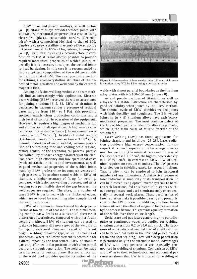
ESW of α- and pseudo α-alloys, as well as low(α + β) titanium alloys provides welded joints withsatisfactory mechanical properties in a case of usingelectrodes (plates, consumable nozzles, electrodewires) with a composition identical to that of BM,despite a coarse-crystalline martensite-like structureof the weld metal. In ESW of high-strength two-phase(α + β) titanium alloys using electrodes close in com-position to BM it is not always possible to providerequired mechanical properties of welded joints, es-pecially if it is necessary to subject the welded jointsto heat hardening. In this case it is recommended tofind an optimal composition of the weld metal, dif-fering from that of BM. The most promising methodfor refining a coarse-crystalline structure of the de-posited metal is to affect the weld pool by the externalmagnetic field.
Among the fusion welding methods the beam meth-ods find an increasingly wide application. Electronbeam welding (EBW) received the widest acceptancefor joining titanium [3--5, 8]. EBW of titanium isperformed in vacuum (under a pressure of residualgases ranging from 1⋅10--3 to 1 Pa), this providingenvironmentally clean production conditions and ahigh level of comfort in operation of the equipment.However, it requires a high degree of mechanisationand automation of all operations. A high energy con-centration in the electron beam (the maximum powerdensity is 5⋅107 W/cm2), locality of metal heating(the lowest density in a cross section is 1⋅10--4 cm2),minimal distortion of metal welded, vacuum protec-tion of the welding zone and cooling weld regions,remote control of the technological process, precisecontrollability of space-energy parameters of the elec-tron beam, high efficiency and low operational costs(with substantial initial capital investments), as wellas good mechanical properties of the welded jointsmade by EBW predetermine its competitiveness andhigh prospects. To produce sound welds in EBW oftitanium, a higher accuracy of fit-up for welding,compared with fusion arc welding processes, and strictkeeping to a permissible size of the gap between theweld edges are required. Therefore, in a number ofcases EBW is performed with the thickened edges,which are removed by machining after completion ofthe welding process.
EBW of titanium is characterised by deep pene-tration at low values of heat input. The minimal melt-ing zone in EBW leads to a substantial decrease indistortion of workpieces, compared with other fusionwelding methods. EBW of titanium can be used tomake the fundamentally new types of the welds, e.g.joining of structural members located at differentheight, welding in narrow gaps, as well as making ofslot welds, where the lower element is accessible fora direct impact by the heat source. EBW of titaniumparts is performed in flat position or with a horizontalbeam and through penetration. The weld can be madeon a horizontal or vertical plane. Horizontal locationof the weld pool provides quality formation of the
welds with almost parallel boundaries on the titaniumalloy plates with b ≥ 100--150 mm (Figure 8).
α- and pseudo α-alloys of titanium, as well asalloys with a stable β-structure are characterised bygood weldability when joined by the EBW method.The thermal cycle of EBW provides welded jointswith high ductility and toughness. The EB weldedjoints in (α + β) titanium alloys have satisfactorymechanical properties. The most common defect ofthe EB welded joints in titanium alloys is porosity,which is the main cause of fatigue fracture of theweldments.
Laser welding (LW) has found application forjoining titanium and its alloys [25--28]. Laser radia-tion provides a high energy concentration. In thisrespect it is much superior to other energy sourcesused for welding (the minimal cross section area ofthe laser beam is 1 ⋅10--6 cm2, the highest power densityis 1⋅109 W/cm2). In contrast to EBW, LW of tita-nium requires no vacuum chambers. The LW processis carried out in shielding gases, i.e. argon or helium.That is why it can be employed to join structuralmembers of any dimensions. A distinctive feature oflaser radiation is simplicity of its transportation. Itcan be directed using optical mirror systems to hard-to-reach locations, fed to substantial distances with-out energy losses, and used simultaneously or sequen-tially in several work places. These peculiarities oflaser radiation make it possible to easily and promptlycontrol the LW process. In addition, the laser beamis insensitive to the effect of magnetic fields generatedby the process fixture. This provides quality formationof the welds over their entire length.
Solid-state and gas lasers generating the periodic-pulse or continuous waves are applied for weldingtitanium plates from 0.2 to 25.0 mm thick. The proc-esses of automatic and manual LW of small sectionscan be carried out both in the CW and pulsed modes(seam and spot welding). LW with deep penetrationis performed only in the automatic mode. Advantagesof LW with deep penetration are especially pro-nounced in welding of titanium. Comparison of EBWand LW as to their technological and economical pa-rameters shows that LW is indicated for welding of
Figure 8. Macrosection of butt welded joint 120 mm thick madein titanium alloy VT6 by EBW using a horizontal beam
2/2005 41

metal plates with b ≤ 5 mm (the beam power is upto 4 kW), and EBW is more economically advanta-geous for welding of titanium plates with b ≥ 10 mm(the beam power is more than 10 kW). LW requiresthat the laser beam be precisely guided and exert astable effect. The laser welds are characterised by ahigh quality, which in the majority of cases allowsavoidance of their subsequent treatment. Mechanicalproperties of laser welded joints in titanium are at alevel of properties of BM. Drawbacks of LW includea high cost of laser radiation sources. A serious prob-lem in LW of titanium is formation of pores in theroot part of the welds, which is caused by a drasticchange in solubility of gases during rapid cooling andsolidification of metal.
Ion-beam welding of titanium in vacuum with acontrolled evolution of gases (oxygen, nitrogen) fromthe welds involves the use of high-density ion flows.Electron-ion welding can be used to alloy the weldmetal. However, at present these welding processes[29, 30], as well as the light beam welding process[31], find no practical application.
Fabrication of welded structures with high techno-logical and economical indicators always involves theneed to select a welding method, which has to corre-spond to the maximal possible degree to specific pro-duction and service conditions. The proper choice of awelding method provides the required quality and effi-ciency of specific welding joints, which eventually af-fects the technical level of production of the weldments,as well as their performance and life. Modern fusionwelding methods allow successful joining of titaniumplates with thickness ranging from fractions of a milli-metre (laser and microplasma welding) to tens of cen-timetres and more (EBW and ESW).
Several versions of value analysis (VA) were devel-oped and found commercial application for selection ofa welding technology or its improvement. VA is amethod for system examination of an object (workpiece,process, structure), which is intended for revealing andutilisation of the improvement reserves. The main initialcondition of VA is that each object has functionallyexcessive costs, which can be revealed, eliminated orutilised in a more efficient way [32].
1. Gorynin, I.V., Gechulin, B.B. (1990) Titanium in machine-building. Moscow: Mashinostroenie.
2. Shelenkov, G.M., Blashchuk, V.E., Melekhov, R.K. et al.(1984) Manufacture and operation of titanium equipment.Kiev: Tekhnika.
3. Gurevich, S.M., Zamkov, V.N., Blashchuk, V.E. et al.(1986) Metallurgy and technology of welding titanium andits alloys. Kiev: Naukova Dumka.
4. Gurevich, S.M. (1990) Reference book on welding of non-ferrous metals. Kiev: Naukova Dumka.
5. Zamkov, V.N., Prilutsky, V.P., Shevelev, A.D. (1992)Metallurgy and technology of welding titanium alloys. In:Welding and Surfacing Rev. Vol. 2.
6. (1997) Forming, welding, brazing and heat treatment of ti-tanium and its alloys in aircraft engineering. Ed. by A.G.Bratukhin. Moscow: Mashinostroenie.
7. (1998) AWS Welding Handbook. Vol. 4.8. Nazarenko, O.K., Kajdalov, A.A., Kovbasenko, S.N. et al.
(1987) Electron beam welding. Ed. by B.E. Paton. Kiev:Naukova Dumka.
9. (2000) Specialized gas shielding for titanium. Welding J.,3, 56.
10. Dolotov, B.I., Muraviov, V.I., Ivanov, Yu.L. et al. (1997)Immersed tungsten electrode welding of VT20 alloy on non-treated edges. Svarochn. Proizvodstvo, 7, 25--27.
11. Chernysh, V.P., Kuznetsov, V.D., Briskman, A.N. et al.(1983) Welding with electromagnetic stirring. Kiev:Tekhnika.
12. Zamkov, V.N., Topolsky, V.F., Kushnirenko, N.A. (1978)Twin-arc tungsten-electrode welding of thick titaniumplates. Avtomatich. Svarka, 2, 44--47.
13. Belous, V.Yu. (2002) Narrow-gap arc welding of titaniumalloys (Review). The Paton Welding J., 9, 35--39.
14. Paton, B.E., Zamkov, V.N., Prilutsky, V.P. (1996) Narrow-groove welding proves its worth on thick titanium. WeldingJ., 5, 37--41.
15. Tsaryuk, A.K. (1998) Welding of tubes to tube plates (Re-view) Avtomatich. Svarka, 4, 25--29.
16. Nikitin, V.B., Stepanov, V.I. (2001) Manufacture of heatexchanging apparatuses using titanium alloys for the «Al-kholma» heat power plant. Tekhnologiya Mashinostroeniya,2, 53--57.
17. (1996) Customized orbital welding meets the challenge oftitanium welding. Welding J., 12, 39--41.
18. Tsaryuk, A.K. (2000) Equipment for welding of tubes totube plates. Svarshchik, 4, 12--13.
19. Blashchuk, V.E., Onoprienko, L.M., Shelenkov, G.M. etal. (1993) Plasma welding of titanium alloys. Avtomatich.Svarka, 3, 31--33.
20. (1979) Microplasma welding. Ed. by B.E. Paton. Kiev:Naukova Dumka.
21. Nerovny, V.M. (2001) Vacuum arc welding of titanium al-loys. Tekhnologiya Mashinostroeniya, 2, 27--30.
22. Gorbach, V.D., Khvalynsky, V.N. (2002) New technologiesfor manufacture of marine engineering load-carrying spheri-cal structures. Svarochn. Proizvodstvo, 7, 28--33.
23. Zamkov, V.N., Lychko, I.I., Topolsky, V.F. (1999) ESW ofplates of grade 5 titanium alloy. Avtomatich. Svarka, 9,73--75.
24. Yushchenko, K.A., Lychko, I.I., Sushchuk-Slyusarenko, I.I.(1999) Effective techniques of electroslag welding and pros-pects for their application in welding production. In: Wel-ding and Surfacing Rev. Vol. 12.
25. Gedopt, J., Delarbre, E. (2003) Pulsed Nd:YAG laser wel-ding of titanium EAR implants. In: Proc. of Int. Conf. onLaser Technologies in Welding and Materials Processing,Katsiveli, Ukraine, May 19--23, 2003. Kiev: PWI.
26. Gavrilyuk, V.S., Zhilkin, A.M., Ivanov, N.L. (2000) Lasertreatment of materials. Tekhnologiya Metallov, 5, 32--44.
27. Abbott, D.H., Arcella, F.G. (1998) Laser forming of titani-um components. Advanced Materials and Processes,153(5), 29--30.
28. Pronin, M.M., Startsev, V.N., Popov, V.O. et al. (1999)Laser treatment of materials. Voprosy Materialovedeniya,3, 375--393.
29. Gabovich, M.D., Protsenko, M.D., Poritsky, V.Ya. et al.(1980) Ion-beam welding of titanium alloy VT6. Avtoma-tich. Svarka, 2, 69--70.
30. Gabovich, M.D., Khomich, V.A., Nazarenko, O.K. (1993)Electron beam welding with weld alloying. Ibid., 10, 49--50.
31. Frolov, V.A., Pronin, N.S., Fyodorov, S.A. et al. (2003)Development and advancement of technology for light beamwelding, brazing and heat treatment. Svarochn. Proizvod-stvo, 11, 19--21.
32. Demchishev, P.G., Mariin, S.B. (2004) Express-VA im-mersed tungsten-electrode welding process. Svarka v Sibiri,1, 31--34.
42 2/2005
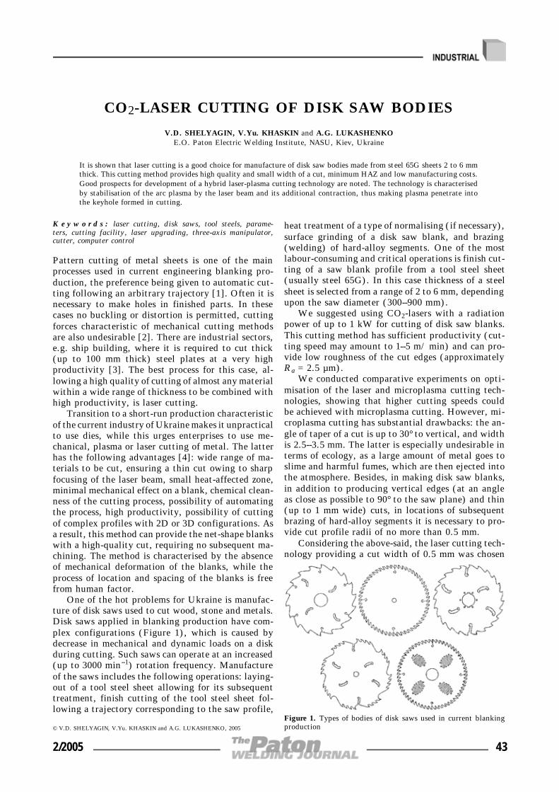
CO2-LASER CUTTING OF DISK SAW BODIES
V.D. SHELYAGIN, V.Yu. KHASKIN and A.G. LUKASHENKOE.O. Paton Electric Welding Institute, NASU, Kiev, Ukraine
It is shown that laser cutting is a good choice for manufacture of disk saw bodies made from steel 65G sheets 2 to 6 mmthick. This cutting method provides high quality and small width of a cut, minimum HAZ and low manufacturing costs.Good prospects for development of a hybrid laser-plasma cutting technology are noted. The technology is characterisedby stabilisation of the arc plasma by the laser beam and its additional contraction, thus making plasma penetrate intothe keyhole formed in cutting.
K e y w o r d s : laser cutting, disk saws, tool steels, parame-ters, cutting facility, laser upgrading, three-axis manipulator,cutter, computer control
Pattern cutting of metal sheets is one of the mainprocesses used in current engineering blanking pro-duction, the preference being given to automatic cut-ting following an arbitrary trajectory [1]. Often it isnecessary to make holes in finished parts. In thesecases no buckling or distortion is permitted, cuttingforces characteristic of mechanical cutting methodsare also undesirable [2]. There are industrial sectors,e.g. ship building, where it is required to cut thick(up to 100 mm thick) steel plates at a very highproductivity [3]. The best process for this case, al-lowing a high quality of cutting of almost any materialwithin a wide range of thickness to be combined withhigh productivity, is laser cutting.
Transition to a short-run production characteristicof the current industry of Ukraine makes it unpracticalto use dies, while this urges enterprises to use me-chanical, plasma or laser cutting of metal. The latterhas the following advantages [4]: wide range of ma-terials to be cut, ensuring a thin cut owing to sharpfocusing of the laser beam, small heat-affected zone,minimal mechanical effect on a blank, chemical clean-ness of the cutting process, possibility of automatingthe process, high productivity, possibility of cuttingof complex profiles with 2D or 3D configurations. Asa result, this method can provide the net-shape blankswith a high-quality cut, requiring no subsequent ma-chining. The method is characterised by the absenceof mechanical deformation of the blanks, while theprocess of location and spacing of the blanks is freefrom human factor.
One of the hot problems for Ukraine is manufac-ture of disk saws used to cut wood, stone and metals.Disk saws applied in blanking production have com-plex configurations (Figure 1), which is caused bydecrease in mechanical and dynamic loads on a diskduring cutting. Such saws can operate at an increased(up to 3000 min--1) rotation frequency. Manufactureof the saws includes the following operations: laying-out of a tool steel sheet allowing for its subsequenttreatment, finish cutting of the tool steel sheet fol-lowing a trajectory corresponding to the saw profile,
heat treatment of a type of normalising (if necessary),surface grinding of a disk saw blank, and brazing(welding) of hard-alloy segments. One of the mostlabour-consuming and critical operations is finish cut-ting of a saw blank profile from a tool steel sheet(usually steel 65G). In this case thickness of a steelsheet is selected from a range of 2 to 6 mm, dependingupon the saw diameter (300--900 mm).
We suggested using CO2-lasers with a radiationpower of up to 1 kW for cutting of disk saw blanks.This cutting method has sufficient productivity (cut-ting speed may amount to 1--5 m/min) and can pro-vide low roughness of the cut edges (approximatelyRa = 2.5 µm).
We conducted comparative experiments on opti-misation of the laser and microplasma cutting tech-nologies, showing that higher cutting speeds couldbe achieved with microplasma cutting. However, mi-croplasma cutting has substantial drawbacks: the an-gle of taper of a cut is up to 30° to vertical, and widthis 2.5--3.5 mm. The latter is especially undesirable interms of ecology, as a large amount of metal goes toslime and harmful fumes, which are then ejected intothe atmosphere. Besides, in making disk saw blanks,in addition to producing vertical edges (at an angleas close as possible to 90° to the saw plane) and thin(up to 1 mm wide) cuts, in locations of subsequentbrazing of hard-alloy segments it is necessary to pro-vide cut profile radii of no more than 0.5 mm.
Considering the above-said, the laser cutting tech-nology providing a cut width of 0.5 mm was chosen
© V.D. SHELYAGIN, V.Yu. KHASKIN and A.G. LUKASHENKO, 2005
Figure 1. Types of bodies of disk saws used in current blankingproduction
2/2005 43

for the given application. It meets the above require-ments to the manufacture of disk saw blanks. Figure 2shows dependence of the cutting speed upon the thick-ness of a cut sheet of steel 65G. The dependence wasderived in optimisation of the laser cutting technologyusing CO2-laser with mode TEM10. To implement thistechnology, the E.O. Paton Electric Welding Insti-tute developed the special computer-controlled auto-mated facility (Figure 3). The Bulgarian 1.3 kW laser«Hebr-1A», produced in 1989, which we upgraded,is used as a technological laser in the facility [5]. Toensure consistent operation of the laser, the water-cooling system of ballast resistors is replaced by re-sistors with air cooling. Lining of the gas-dischargechamber and composition of a working gas mixtureare also changed. The latter is important in terms ofeconomic operation of the laser. According to certifi-cate data, gas mixture CO2:N2:He should be in a ratioof 1:10:30, but in this case one bottle of helium (themost expensive gas) is sufficient only for 40 h ofoperation. So, we changed this proportion to 1:6:4,which allowed us to extend the time of using a heliumbottle to 200 h at a laser radiation power of 1 kW.Therefore, the cost of 1 h operation of the laser wasdecreased 5 times.
In the developed facility the three-axis manipula-tor «Granit-1600» of an ingenious design is used tomove the «flying» optics. Compressed air under apressure of more than 0.3 MPa and electric motorswith a linearly flared-out stator are used to move thebeam (axis y) and carriage (axis x) along the polishedgranite guides. Movement of a cutting head (axis z)is carried out from the electric motor with a rotatingrotor. The values of movement of the tool (cuttinghead) along the axes are as follows: x:y:z == 1500:1000:50 mm, the speed of operation in theautomatic mode ranging from 0.01 to 22 m/min. Pre-cision of positioning of the tool is not lower than±3 µm/m.
The circular variable-capacitance transducer lo-cated about a cutting nozzle is applied to stabiliseposition of the focus with respect to a metal sheetbeing cut. Two water-cooled rotating mirrors of gold-plated silicon and focusing lenses of potassium chlo-ride single crystal with a focal distance of 150, 200and 300 mm are employed in the optical tract. To
Figure 2. Dependence of speed v of 700 W CO2-laser cutting uponthickness h of steel 65G sheet cut with compressed air (1), air-oxygen mixture with a component ratio of 3:1 (2) and oxygen (3)used as a cutting gas
Figure 3. Computer-controlled automated technological facilityfor laser cutting based on upgraded CO2-laser «Hebr-1A»
Figure 4. Schematic diagram of laser cutter used in the techno-logical facility for laser cutting of disk saw bodies: 1 ---- casing;2 ---- connection for air cooling of lens; 3 ---- focusing lens; 4 ----connection for feeding of cutting gas; 5 ---- manometer; 6 ---- cuttingnozzle alignment system; 7 ---- cutting nozzle
44 2/2005

extend the life of the lenses, their air cooling is pro-vided for in our design of the laser cutter (Figure 4).
Computer based on a processor operating at a fre-quency of not lower than 300 MHz and CNC systemare used to control the laser facility. The control soft-ware developed for OS Windows makes it possible toautomatically convert the files of drawings stored inAutoCAD 2000 and higher into its format. Therefore,there is no need to convert design documents intomachine codes.
One of the key points of adaptation of the tech-nological process of laser cutting of steel 65G sheetsto peculiarities of the developed facility is selectionof shape and diameter of a cutting nozzle, as well ascomposition of a cutting gas. Air, air-oxygen mixture(in different proportions) and pure oxygen were usedas a cutting gas (see Figure 2).
As established experimentally, it is reasonable toreduce diameter of the cutting nozzle approximatelyto a diameter of the focused laser beam passingthrough it (to 0.6 mm in our case) and make it asclose as possible in shape to the Laval nozzle [6].Cutting should be performed in pure oxygen.
This approach does not only lead to rise in pro-ductivity, but also allows the cut to be narrowed, thesize of flash at the cut edges to be minimised and,hence, wastes and harmful fumes formed in cuttingto be reduced, the flow rates of oxygen being com-paratively low (150--200 l/h). Continuous air coolingof the upper part of a lens with periodic (correspond-ing to laser radiation) feed of oxygen makes it possibleto avoid thermal cracking of the lens, and the lenslocation seal prevents mixing of air with oxygen. Theexperiments proved high prospects of the hybrid la-ser-plasma cutting technology, in which plasma pene-trates into the keyhole. A practical example of appli-cation of laser cutting is a disk saw body (Figure 5),which was cut using our automatic facility.
CONCLUSIONS
1. Laser cutting, providing an improved quality anddecreased (4--6 times) width of a cut, is a good choicefor manufacture of bodies of saw disks made from2--6 mm thick sheets of steel 65G, despite a highercost of laser equipment. The use of laser cutting allows
the size of HAZ to be decreased and some finishingoperations to be eliminated, which decreases the costsof manufacture of disk saws.
2. Decrease in the cut width leads to a substantialdecrease in the amount of slime and harmful fumesejected into the atmosphere. This factor is importantfor mass production in terms of ecology, and it shouldbe taken into account in selection of technology anddevelopment of equipment.
1. Aichele, G., Nickenig, L. (2003) Laserstrahlschneiden ----Maschinenbauarten und zu trennende Werkstoffe. Prak-tiker, 10, 302, 304--306.
2. Muraviov, V.I., Matvienko, D.V., Mariin, B.N. (2003) Ef-fect of gas-laser cutting in commercial nitrogen atmosphereon properties of titanium alloy welded joints. Svarka v Si-biri, 2(10), 33--35.
3. Hencock, R. (2003) Laser-oxygen cutting of steel sheets upto 75 mm thick. Svarshchik, 6, 18--19.
4. Grigoriants, A.G., Sokolov, A.A. (1988) Laser techniqueand technology. In: Laser cutting of metals. Manual for in-stitutes for higher education. Book 7. Ed. by A.G. Grigori-ants. Moscow: Vysshaya Shkola.
5. Abilsiitov, G.A., Golubev, V.S., Gontar, V.G. et al. (1991)Technological lasers. Refer. Book. Vol. 1: Calculation, de-sign and service. Ed. by G.A. Abilsiitov. Moscow: Mashi-nostroenie.
6. (1973) Large Soviet Encyclopedia. 3rd ed. Vol. 14, 242.Moscow: Sov. Entsiklopediya.
Figure 5. Body of a disk saw 800 mm in diameter made from steel65G sheet 5 mm thick
2/2005 45

TECHNOLOGICAL PECULIARITIESOF HIGH-ALLOY STEEL WELDING
BY ELECTRODES WITH RUTILE COATING
I.N. VORNOVITSKY1, N.V. ZAKHAROVA1, O.V. SHISHKOVA1, A.A. VILISOV2 and A.V. ZINCHENKO2
1Closed Joint Stock Company «Elektrod», Zheleznogorsk, Russia2Personnel Upgrading Center, Perm, Russia
The paper presents the technological advantages of rutile type electrodes for high-alloy steel welding, compared toelectrodes with a basic coating type. Information is given on the new grades of electrodes, d eveloped at CJSC «Elektrod».
K e y w o r d s : arc welding, stainless steels, coated electrodes,rutile type coating, technological properties
Specialists of Company «Elektrod» developed a seriesof grades of electrodes with rutile coating for weldingof high-alloy steels. These electrodes are branded witha letter-digit designation ZhZL (ZhZ stands forZheleznogorsk Plant, L ---- for welding of high-alloysteels). Table 1 presents certain characteristics of theelectrodes. The «Elektrod» continues developing andimproving electrodes with rutile and other coatingtypes for welding of high-alloy steels and alloys. Suchknown electrode grades as OZL-17U, ANZhR-1.ANZhR-2 and others are their prototypes.
In the last twenty-thirty years the way of usingthe electrodes with rutile coating for welding of high-alloy steels has changed as against electrodes with abasic coating for the same purpose. Analysis of theinformation [1--3] allows a statement that a share ofrutile-coated electrodes in the total volume of theelectrodes produced for welding of high-alloy steelsis about 80 %, the rest are the electrodes with thebasic and other coatings.
A share of electrodes with rutile coating for weld-ing of high-alloy steels makes up in the post-sovietterritory only 10 %, though during several decades
the Moscow Experimental Welding Plant, the E.O.Paton Electric Welding Institute and a number ofother organizations [4, 5] have been actively involvedinto their development and improvement.
Advantage of the electrodes with rutile coating isin their high technological maneuvering ability,which essentially facilitates the work of the welder,decreases labor intensity and provides high quality ofwelded joints.
The rutile electrodes are characterized with an easystriking and a repeated striking of arc, a possibilityto weld with AC and DC, spray metal transfer andformation of a smooth fine-ripple weld surface facili-tating easy and often spontaneous detachment of theslag whose thermal expansion coefficient is 1.5 timeshigher than in the basic slag. It is though necessaryto emphasize a small sputtering of the electrode metal.All mentioned properties are provided by a thoroughselection of the coating composition, which containsa considerable fraction of rutile or its products.
Other functional advantages of rutile electrodes(a possibility of welding of thin-plate structure andvertical down welding, increased productivity of theprocess) is determined by the diameter of the electrodeand thickness (weight coefficient) of the coating. Inthis case the weld formation and a number of the
© I.N. VORNOVITSKY, N.V. ZAKHAROVA, O.V. SHISHKOVA, A.A. VILISOV and A.V. ZINCHENKO, 2005
Table 1
New grades of electrodeswith rutile coating
Type of electrode(GOST 10052--75)
Grades of welded steels Grades of prototype electrodes withbasic coating
ZhZL-1 E-08Kh17N8M2 10Kh17N13M2T, 08Kh17N5M3,08Kh16N13M2B
NIAT-1
ZhZL-6 E-10Kh25N13G2 10Kh23N18, 20Kh23N18, 08Kh21N6M2T,08Kh23N6
OZL-6, TsL-25
ZhZL-8 E-07Kh20N9 08Kh18N10, 12Kh18N10T, 08Kh18N12B OZL-8
ZhZL-11 E-08Kh20N9G2B 08Kh18N12B, 08Kh18N12T TsL-11
ZhZL-15 E-08Kh19N10G2B 12Kh18N12T TsT-15
ZhZL-400 E-07Kh19N11M3G2F 08Kh17N13M2T EA-400/10U
ZhZL-NZh/13 E-04Kh20N9 06Kh18N11, 04Kh18N10 UONI-13/NZh-2, OZL-6
ZhZL-395 E-11Kh15N25M6AG2 KhN35VT, Kh15N25AM6 EA-395/9
46 2/2005

above mentioned factors of the electrodes depend onthe behavior of the molten metal and slag. Specifi-cally, viscosity of rutile slags of both non-alloyed andalloyed electrodes is higher than in other types ofcommercial electrode slags. Many skillful welderslearnt how to properly use this property of the slagin welding in different spatial positions.
A higher arc voltage of the electrodes with rutilecoating is another advantage in comparison with elec-trodes with basic coating at practically similar weld-ing current (Table 2).
It is believed that the arc temperature of the elec-trodes with rutile coating is higher than of electrodeswith basic coating while melting rate of the electrodeswith rutile coating is known to be higher than of theelectrodes with the basic coating. These factors sug-gest a necessity to correct the groove shape, for ex-ample, size of the root gap and root face for weldingof butt welds.
With the aim of developing practical guidelinesfor welding with new electrodes special tests werecarried out, their results being presented below.
Due to a very easy striking of the arc the weldpool is formed almost immediately. Its shape, volumeand weight are well exposed to regulation due to thewelding current and electrode displacement velocity.In addition, the weld pool fluidity is regulated, themetal outflow from the weld pool is prevented andthe weld is easily formed in all spatial positions.Rather viscous slag formed under melting of elec-trodes also facilitates this process. It is the slag vis-cosity that prevents outflow of the molten metal fromthe gap during welding of penetration beads, whichenables a skillful welder to form a reverse bead orother shape prescribed in the specifications.
Additional tests permit establishing that with anexcessive thickness of the coating a part of the formedslag leaks in front of the weld pool making it difficultto control the formation of the weld. This may leadto disturbance of its rectilinearity and shape.
It is also established that a stable easily controlledarc is formed during welding with new electrodesallowing for manipulation with the electrode face inmost inconvenient positions for the welder and in allpositions of the weld.
An easy repeated striking of the arc makes it pos-sible to make vertical and overhead welds in the con-tinuous and pulse conditions, i.e. with short-term arcbrake providing a symmetrical formation of the weldof the prescribed size (width and thickness). Thistechnique (a short brake of the arc) allows welding
of the thin-plate metal and thin-walled pipes, forma-tion of the penetration layer of the weld with excessiveor variable clearance by the perimeter of the pipe(because of incorrect assembling and preparation ofpipe butts to the welding).
A possibility to weld with alternating current al-lows using (especially for assembling and repair) sim-ple and available equipment.
Easy and spontaneous detachment of the slag es-sentially decreases the labor intensity of welding op-erations and a probability of formation of slag impu-rities. However, the welder should remember abouta certain danger of getting eye trauma (especially) ifthe slag detachment is too active.
Tests of ZhZL electrodes reveal a somewhat in-creased sensitivity of the electrodes to overheating.Therefore, the welding should be performed withinthe range of currents recommended for every diameterof the electrode under controlled indications of theammeter.
It has been earlier mentioned that a wide use ofelectrodes with rutile coating for welding of high-al-loy steels has been retarded in this country. Probablyone of the reasons is a poor knowledge of the con-sumers and welders about technological peculiaritiesof electrodes with rutile coating recognized in manycountries of the world. The authors hope that thisarticle will play a positive role in successful masteringof high-alloy electrodes with rutile coating, which isas a new progressive material.
1. (2001) Schweissgeraete und Schweisszusaetze. LincolnSmitweld GmbH. Katalog. Netherlande.
2. (2001) Consumable for manual and automatic welding.Welding handbook. Goeteborg: ESAB.
3. (2001) Welding consumable guide. Zika. Israel.4. Sidlin, Z.A. (1985) High-alloy welding electrodes.
Svarochn. Proizvodstvo, 2, 3--5.5. Lipodaev, V.N., Kakhovsky, Yu.N. (1976) Development of
electrodes for welding of stable-austenite alloys EP943 andEP516. In: Abstr. of All-Union Conf. on Welding Consu-mables, Kiev, Oct. 5-7, 1976.
Table 2
Diameterof elec-
trode, mm
Recommended weldingcurrent for electrodes with
coatings, A
Arc voltage in weldingusing electrodes with
coating, V
Basic Rutile Basic Rutile
2.00 40--65 45--65 22 29
2.50 50--85 60--90 22 29
3.25 85--115 80--120 21 30
4.00 105--160 120--170 21 32
2/2005 47

INCREASE OF CORROSION RESISTANCEOF WELDED JOINTS OF HIGH-STRENGTH
ALUMINIUM ALLOYS BY EXPLOSION CLADDING
S.Yu. ILLARIONOV, L.D. DOBRUSHIN, S.G. POLYAKOV and G.E. BOEVAE.O. Paton Electric Welding Institute, NASU, Kiev, Ukraine
Evaluation of explosion welding application was conducted for the case of cladding welded joints of aluminuim alloys7010 and 2024 with pure aluminium. It is shown that such a protection of welds prevents stress corrosion cracking orintercrystalline corrosion.
K e y w o r d s : explosion welding, explosion cladding, frictionstir welding, high-strength aluminium alloys, welded joints,stress-corrosion cracking, intercrystalline corrosion.
Welded joints of aluminium alloys are characterizedwith a lower corrosion resistance as against basic met-al, which is specified by their physical-mechanicaland electromechanical heterogeneity. The latter isvery typical for welded joints of high-strength alu-minium alloys.
Studies of local explosion cladding of weldedjoints produced by friction stir welding (FSW) usingtechnically pure aluminium were conducted as re-quested by the Airbus Industries Company to preventthe contact of the corrosion medium with weld surfaceas well as thermal and thermomechanical effect. Thisis a relatively new welding method patented in 1991by the Welding Institute, Great Britain. The essenceof this method is that a special rotating tool is pene-trated into the butt of the workpiece. As a result offriction, which leads to plasticization of metal aroundthe tool, a heat is evolved subsequently impartinglinear motion to the tool and the workpieces. Themetal passes over the tool pin and moving from heat-ing to cooling zone forms a joint. This method hashigh technological potential and permits producingjoints of a wide range of aluminium alloys includingthermally strengthened ones, as well as steel and cop-per joints [1].
Previously, anticorrosion explosion cladding ofwelded joints of the autoclave reaction cups for pro-ducing concentrated nitric acid was studied at theE.O. Paton Electric Welding Institute [2]. The ap-paratuses were produced of technically pure alu-minium of grade A85 by fusion welding. Claddingwas performed by alloy A85. As a result the durabilityof the autoclave reaction cups increased about 6 times,which proves a correctness of the chosen approach.
The purpose of this work is to evaluate the effi-ciency of using explosion welding (EW) for claddingof FSW joints of high-strength aluminium alloys withtechnically pure aluminium for increasing of their cor-rosion resistance.
Explosion cladding and subsequent tests were car-ried out for the following objects:
• butt joints of 7010 T7651 aluminium alloy plates65 mm thick (σt = 520--525 MPa; σ0.2 = 455--465 MPa;δ = 12--12.5 %) produced by FSW into the depth ofdown to 13 mm;
• butt joints of sheets of aluminium alloy 2024T351 4 mm thick (σt = 435 MPa; σ0.2 = 280 MPa;δ = 15 %) produced by FSW through all thickness ofthe sheets.
Cladding was performed by sheets of alloy 1050(analog AD0) 2 mm thick. Preliminary metal-lographic analysis of welded specimens showed thatthere were sites with grains at a depth of 5 mm orientedperpendicular to the sheet surface in the zone of ther-momechanical effect of FSW joints of alloy 7010.Such location of grains most of all facilitates the de-velopment of intercrystalline corrosion (ICC), so alayer of metal 5 mm thick was removed from thesurface to expose these sites. Besides, a recess wasmade from the side of the FSW weld root for removalof the acute concentrator caused by an incompletejoint penetration.
Considering the necessity to weld the extendedFSW joints a parallel EW scheme was employed whenthe cladding sheet before welding was located parallelto the surface subject to cladding. As against com-monly used angular scheme it is simpler in assemblingand is characterized by an equality of the detonationrate of the explosive D and the rate of the contactpoint Vc of the welded surfaces. Since the qualityjoint for the given pair of metals is achieved at Vc ≈≈ 2 km/s, then a mixture of ammonite # 6ZhV withammonium nitrate was selected as an explosive. Acollision velocity of two sheets determined by thedependencies from the work [3] was about 500 m/s.Criteria of quality of the obtained joint were its equalstrength with the metal of the cladding layer (alloy1050) and the absence of cast metal inclusions on thejoint boundary. Microstructures of the joints of thecladding layer and the FSW weld of alloy 7010, re-spectively, in the longitudinal direction relative tothe EW process and cladding layer, and FSW weldof alloy 2024 are shown in Figure 1.
It is noteworthy that a more ductile metal is ad-visable to use as a cladding layer, therefore alloy 1050was subjected to annealing before EW. Besides, this
© S.Yu. ILLARIONOV, L.D. DOBRUSHIN, S.G. POLYAKOV and G.E. BOEVA, 2005
48 2/2005

contributed to a smaller deformation of the cladsheets, which is especially important for alloy 2024with its thickness about 4 mm. Specimens of the FSWjoints produced by explosion cladding are presentedin Figure 2. Tests on resistance to stress corrosioncracking (SCC) and ICC are carried out to comparecorrosion resistance of clad and non-clad (initial)FSW joints. Tests of the FSW joints of aluminiumalloy 7010 were carried out by the ASTM G 39 [4]and ASTM G 44 standards [5]. The specimens weretested under loading by a four-point scheme (Fi-gure 3). The load in this case was preset by a valueof a maximal deviation of y determined by the formula
y = σ(3H2 -- 4A2)
12Et,
where σ is the preset load assumed as 0.75σy for non-clad FSW joints, MPa; E is the elasticity module,MPa; t is the specimen thickness, mm; H is the dis-tance between external supports, mm; A is the dis-tance between internal and external supports, mm.
The specimens were periodically submerged intochemical solution of 3.5 % NaCl (pH 6.4--7.2) andtested according to the following cycle: 10 min in thesolution, 50 min in the air. The tests lasted 40 days.The specimens were cut so that their length was120 mm (transverse to FSW joint and cladding di-rection), width ---- 15 mm (along the joint) and thick-ness ---- 4 mm. The enamel EP-5147 (TU U6.24514086-044--98 «A») was used to protect thespecimens from the action of the corrosion mediumfrom the edge and lower surfaces of the FSW joints.
The SCC tests of the FSW joints of aluminiumalloy 2024 were carried out by the standardsASTM G 49 [6] and ASTM G 44, the ICC tests ----by the standards ASTM G 110--92 [7] and QVA-Z10-59--03 [8].
The SCC-tested specimens were under permanenttensile load, which (like for the specimens with theFSW joints of alloy 7010) was preset equal to 0.75σyfor initial non-clad joints. Testing regime of clad andnon-clad FSW joints of alloy 2024 was the same asfor the FSW joints of alloy 7010 with the exceptionof their holding under stress and in corrosion mediumbeing 30 days. Specimens for the ICC tests were car-ried out so that their length was 70 mm (transverseto FSW joint and cladding direction), width ----50 mm (along the joint). The specimens were placed
into the corrosion solution (57 g NaCl + 10 ml H2O2(30 %) + 1000 ml H2O) and held there 6 h at thetemperature 30 °C.
The specimens of alloy 7010 (initial and clad)were not destroyed completely during SCC tests. In-itial FSW joints of alloy 7010 were fully covered withcorrosion products. No corrosion traces were observedon the surface of the cladding layer of alloy 1050while on the unprotected part of the clad specimens(parent metal) there were the same corrosion tracesas on the initial specimens. The metallographic analy-sis of the initial specimens after tests showed that allof them are subject to ICC. A typical depth of theICC penetration in the most dangerous ther-momechanically affected zone is 150--160 µm (Fi-gure 4, a) while in one case out of all series of speci-
Figure 3. Scheme of fixation of the alloy 7010 specimen for SCCtests (for designations see the text)
Figure 2. Explosion clad of FSW joints of alloys 7010 (a) and2024 (b)
Figure 1. Microstructures of the joint zone of cladding layer andFS weld on alloy 7010 (a) and 2024 (b) (×100)
2/2005 49

mens it was 720 µm. No corrosion traces of the FSWjoints were observed in the clad specimens (Figure 4,b). Therefore, a cladding layer of technically purealuminium completely excludes any action of the cor-rosion medium on the protected weld.
During the SCC tests under uniaxial tensile loadof the alloy 2024 joint specimens, the initial specimenswere destroyed during the testing period. The presenceof pitting corrosion was observed on the surface ofthe cladding layer but without load it was not at allobserved. The metallographic analysis showed the ab-sence of corrosion of the FSW joint under claddinglayer (Figure 5). Therefore, disregarding the surfacepitting corrosion of the cladding layer, the latter per-formed its function.
The ICC tests showed that there are no corrosiontraces in the clad specimens (Figure 6). A depth of
corrosion penetration in the near-weld zone is 43 µm(Figure 7) and in the thermomechanically affectedzone is 72 µm.
In conclusion it is worth noting that the corrosiontraces were absent in the explosion-clad FSW jointsof alloys 7010 and 2024 after SCC tests, the depth ofICC penetration in the non-clad joints of alloy 7010was 150--160 µm while the joints of alloy 2024 weredestroyed. Besides, a depth of corrosion penetrationin the FSW joints of alloy 2024 achieved 72 µm underICC tests even without loading.
The performed studies have shown a high effi-ciency of the proposed method for protection of theFSW joints of high-strength aluminium alloys againstcorrosion, which allows recommending this methodfor practical application.
1. Tretyak, N.G. (2002) Friction stir welding of aluminium al-loys (Review). The Paton Welding J., 7, 10--18.
2. Petushkov, V.G., Zotov, M.I., Polyakov, S.G. et al. (1989)Corrosion resistance of aluminium welded joints after explo-sion cladding. Avtomatich. Svarka, 1, 21--24.
3. Kudinov, V.M., Koroteev, A.Ya. (1978) Explosion weldingin metallurgy. Moscow: Metallurgiya.
4. ASTM G 39: Standard practice for preparation and use ofbent-beam stress-corrosion test specimens.
5. ASTM G 44: Standard practice for evaluating stress-corro-sion cracking resistance of metals and alloys by alternateimmersion in 3.5 % sodium chloride solution.
6. ASTM G 49: Standard practice for preparation and use ofdirect tension stress-corrosion test specimens.
7. ASTM G 110: Standard practice for evaluating intergranu-lar corrosion resistance of heat-treatable aluminum alloys byimmersion in sodium chloride + hydrogen peroxide solution.
8. QVA-Z10-59--03: Intergranular corrosion test for age-har-denable aluminium alloys.
Figure 4. Microstructure of thermomechanically affected zone ininitial (a) and clad (b) FSW joint of alloy 7010 after SCC test(×100)
Figure 5. Microstructure of thermomechanically affected zone inthe clad FSW joint of alloy 2024 after SCC tests (×100)
Figure 6. Microstructure of clad FSW joint of alloy 2024 afterICC test (×100)
Figure 7. Microstructure of initial FSW joint of alloy 2024 afterICC test (×100)
50 2/2005

SOURCES OF BEAM HEATING FOR BRAZING(REVIEW)
A.M. ZHADKEVICHE.O. Paton Electric Welding Institute, NASU, Kiev, Ukraine
The paper deals with the features of development of the design and application of technologies using the electron beam,laser, quartz lamps, as well as solar energy. It is shown that the inertialess heat sources enable controlling the heatinput in a broad range, which allows considerable widening of the scope of brazed materials. Intensive development ofthe technique of brazing using concentrated heat sources is noted.
K e y w o r d s : brazing, electron beam, laser, infrared radia-tion, heat source, quartz lamp, history of engineering.
In the history of the development of joining processesthe second half of the 20th century was marked bythe beginning of the transition period, which implieda transition to a wide application of the intensivebrazing processes. This was conditioned by the ap-pearance of new materials and more complex condi-tions of their exploitation. Often a quality of thejoints of new materials can be insured only by brazing.However, at the same time it was discovered thatchemical erosion of the base material was the maindisadvantage of main brazing processes. Besides,among other factors influencing the intensity anddepth of erosion much significance is attached to aperiod of stay of the brazing filler alloy in the liquidstate, the interval between the liquidus and solidusof the brazed metal--filler alloys [1, 2]. Therefore, thenecessity arose to develop the brazing technologiesbased on the concentrated heating sources.
Since 1960s the designers of products of differentpurposes became interested in technological peculi-arities of brazing. Specific requirements to heatingdeveloped from micro-miniaturization of the elec-tronic devices and minimization of their weight in thelarge-scale structures of aviation-space engineering,nuclear power engineering etc. A number of organi-zations in the USSR launched comprehensive re-searches whose ultimate objective was to providequality of the brazed articles for critical use employingthe newest materials. These researches took into con-sideration the temperature conditions, design feasi-bility of the article, peculiarities of the metallurgicalcorrelation of the brazed metal, technological natureof the structure, endurance of joints, their corrosionresistance and aging tendency, requirements to dura-bility and reliability [3, 4].
The results obtained in the 1960s allowed theUSSR to become the leader in development and ap-plication of the technology of brazing of special arti-cles including the brazing of non-organic dielectrics,cermets and other materials with metals. High tem-perature resistance, mechanical strength wereachieved and a number of other stringent requirements
to the super-powerful electronic, electric-vacuumSHF devices, power nuclear energy units, articles forthermonuclear synthesis and acceleration engineeringetc. were met [5].
Even though the brazing with beam energy sourceshas been already used for several decades no attemptshave been made so far to generalize the results of thestudies on the brazing techniques, history of the de-velopment of technologies and equipment. So, in fun-damental work [6] nothing is said in the overviewsection about brazing by beam sources. In this andother works [1, 2, 4--6] the data are not systematizedand no comparison is made on peculiarities and po-tentialities of different sources of beam heating, therange of their optimal application is not established.
The aim of this work is to conduct a retrospectiveanalysis of beam brazing methods, comparison ofschemes and principles of heating, analysis of possi-bilities and peculiarities of the brazing techniques onspecific examples and the results of applications inmanufacturing of modern articles.
High concentration of energy, inertialessness ofheating sources of articles, a possibility to accuratelyregulate the regime parameters are the most importantproperties of the basic beam technologies (welding,brazing, heat treatment, cutting etc.). Electron beamwith its universal possibilities is widely applied. Dur-ing the last two decades the researchers and producerspaid much attention to the development of laser tech-nologies. Creation of artificial beam energy sourceswas conditioned by a wide scope of the works in thesphere of electricity in the early 19th century whilein the mid of the 19th ---- by intensive studies ofphysical phenomena on the molecular-electronic level.Particularly, heat action of electron beams and infra-red radiation were discovered and practically appliedfor the first time. Devices for different technologiesof material treatment were designed in the first halfof the 20th century, in the second half of the 20thcentury the electron beam welding and in the end ofthe 20th century the laser welding were developedand found extensive application. At the same timebrazing technologies with the same heating sourceswere developed in a number of countries.© A.M. ZHADKEVICH, 2005
2/2005 51

Electron beam treatment is based on heating thearticle with a heat evolved under moderation of theflow of electrons accelerated to high energies. TheEnglish physicist W. Crooks (1869) was the first toobserve electron beams as a blue glowing along gas-discharge tube. Ten years after he discovered that thecathode beams may fuse metals including refractoryplatinum. Even earlier in 1852 V.G. Grove made simi-lar presentation in the London Royal Society. How-ever, only after discovery of electrons by G.G. Thom-son in 1897 the American physicist R. Milliken asso-ciated the beams with the flow of electrons. Forma-tion, focusing and deviation of electron beams at-tracted attention of scientists from many countries.As early as in the end of the 19th century the electronbeams were applied in practice initiating thereby ascientific direction called electronic and ionic optics.The idea of deviation of the electron beam was prac-tically implemented in 1897 by the German physicistK.F. Braun (by magnetic field) and by the Englishphysicist G.G. Thomson (by electrostatic field).
Experiments and attempts to apply the electronbeams for melting metals continued in the 20th cen-tury. However, a level of development of vacuum andelectronic engineering was still insufficient for devel-opment of industrial technologies based on transfor-mation of kinetic energy of electron flows into heatingone during interaction with the surface of the heatedbody. Electron beam units for melting of niobium andtantalum ingots were created only in the beginningof the 1950s. Creation of high-production vacuumpumping systems, EB guns capable to provide a stable
technological process and reliable systems of powersupply and control of the guns accelerated introduc-tion of EB units in the metallurgy of pure metals andalloys [7].
The first technologies and units for EBW weredeveloped in the 1950s by J. A. Stohr, G. Briola(France), W.L. Wyman (USA) [8, 9], N.A. Olshan-sky, B.A. Movchan, D.M. Rabkin, S.M. Gurevich,O.K. Nazarenko, S.D. Zagrebenyuk (USSR) [10, 11].For a short period of time the methods of formationof electron beam, constructions of EB units with vac-uum chambers up to several dozens of cubic metersin volume, cap chambers for local treatment are de-veloped as well as advantages and a range of rationalapplication of the EBW are determined and produc-tion of the equipment is organized. As to brazingtechnology, then electron beam heating (EBH) cameinto use for different experiments of brazing of high-accuracy articles assembled of thin-walled elementsdifferent in thickness and for manufacturing of unitsand structures of active and refractory metals.
V.F. Khorunov, Yu.B. Malevsky and others fromthe E.O. Paton Electric Welding Institute studieddeformations, structural transformation and othercharacteristics of certain methods of brazing con-ducted in the vacuum unit with circular EBH [12].In this case cyclic heating in different temperatureand time intervals was achieved with sufficiently highaccuracy. A.N. Kabanov, A.A. Kafarov and othersfrom the Research Institute of Aviation Engineeringdeveloped several models of EB units ELURO forprecision welding, brazing and size treatment with apossibility to regulate total and specific power in thebeam within a wide range both in the pulse and con-tinuous regimes (Figure 1) [13, 14]. The achievedspecific power 5⋅108 W/cm3 allowed treating almostall available materials. The unit ELURO is employedto produce special articles for electronic engineering.The microscope and a displacement mechanism incor-porated in the unit provide alignment of the electronbeam and a joint zone with ±5 µm accuracy underbrazing of gold wire 80 µm in diameter to thenichrome-manganese silver on the glass (thickness oflayers is 30 and 800 nm; a silver layer 600--800 nmthick as a filler alloy) [15]. EBH was applied toproduce through leads in the dielectric and semicon-ducting materials with high density and location ac-curacy. In this case one and the same unit is employedto drill holes (several dozens of micrometers in di-ameter) to where the wires are inserted (kovar andothers) and to braze with a «softer» electron beam.It is proved possible to achieve high accuracy in po-sitioning of leads ---- five wires positioned on 1 mm2
gave only 10 µm of deviation from the preset geometry[15]. The industry and research organizationslaunched the production of other types of units.
Scanning of the flow of electrons is used for EBHof large area of joints. To achieve a uniform heatingof the brazing zone in the units of ELU-4 type theelectron beam oscillates when pulse beams of different
Figure 1. Schematic diagram of ELURO unit: I ---- high-voltagerectifier; II ---- voltage stabilizer, modulator, sections of glow andbias voltage; III--V ---- power sources of aligning coils of stigmatorand lens; VI ---- power unit of raster electron microscope; VII ----power supply to the table engine; VIII ---- pumping system
52 2/2005
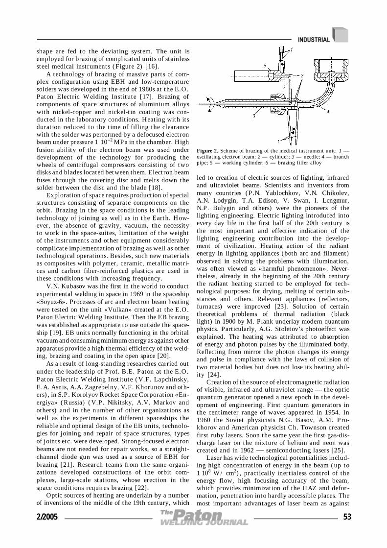
shape are fed to the deviating system. The unit isemployed for brazing of complicated units of stainlesssteel medical instruments (Figure 2) [16].
A technology of brazing of massive parts of com-plex configuration using EBH and low-temperaturesolders was developed in the end of 1980s at the E.O.Paton Electric Welding Institute [17]. Brazing ofcomponents of space structures of aluminium alloyswith nickel-copper and nickel-tin coating was con-ducted in the laboratory conditions. Heating with itsduration reduced to the time of filling the clearancewith the solder was performed by a defocused electronbeam under pressure 1 ⋅10--2 MPa in the chamber. Highfusion ability of the electron beam was used underdevelopment of the technology for producing thewheels of centrifugal compressors consisting of twodisks and blades located between them. Electron beamfuses through the covering disc and melts down thesolder between the disc and the blade [18].
Exploration of space requires production of specialstructures consisting of separate components on theorbit. Brazing in the space conditions is the leadingtechnology of joining as well as in the Earth. How-ever, the absence of gravity, vacuum, the necessityto work in the space-suites, limitation of the weightof the instruments and other equipment considerablycomplicate implementation of brazing as well as othertechnological operations. Besides, such new materialsas composites with polymer, ceramic, metallic matri-ces and carbon fiber-reinforced plastics are used inthese conditions with increasing frequency.
V.N. Kubasov was the first in the world to conductexperimental welding in space in 1969 in the spaceship«Soyuz-6». Processes of arc and electron beam heatingwere tested on the unit «Vulkan» created at the E.O.Paton Electric Welding Institute. Then the EB brazingwas established as appropriate to use outside the space-ship [19]. EB units normally functioning in the orbitalvacuum and consuming minimum energy as against otherapparatus provide a high thermal efficiency of the weld-ing, brazing and coating in the open space [20].
As a result of long-standing researches carried outunder the leadership of Prof. B.E. Paton at the E.O.Paton Electric Welding Institute (V.F. Lapchinsky,E.A. Asnis, A.A. Zagrebelny, V.F. Khorunov and oth-ers), in S.P. Korolyov Rocket Space Corporation «En-ergiya» (Russia) (V.P. Nikitsky, A.V. Markov andothers) and in the number of other organizations aswell as the experiments in different spaceships thereliable and optimal design of the EB units, technolo-gies for joining and repair of space structures, typesof joints etc. were developed. Strong-focused electronbeams are not needed for repair works, so a straight-channel diode gun was used as a source of EBH forbrazing [21]. Research teams from the same organi-zations developed constructions of the orbit com-plexes, large-scale stations, whose erection in thespace conditions requires brazing [22].
Optic sources of heating are underlain by a numberof inventions of the middle of the 19th century, which
led to creation of electric sources of lighting, infraredand ultraviolet beams. Scientists and inventors frommany countries (P.N. Yablochkov, V.N. Chikolev,A.N. Lodygin, T.A. Edison, V. Swan, I. Lengmur,N.P. Bulygin and others) were the pioneers of thelighting engineering. Electric lighting introduced intoevery day life in the first half of the 20th century isthe most important and effective indication of thelighting engineering contribution into the develop-ment of civilization. Heating action of the radiantenergy in lighting appliances (both arc and filament)observed in solving the problems with illumination,was often viewed as «harmful phenomenon». Never-theless, already in the beginning of the 20th centurythe radiant heating started to be employed for tech-nological purposes: for drying, melting of certain sub-stances and others. Relevant appliances (reflectors,furnaces) were improved [23]. Solution of certaintheoretical problems of thermal radiation (blacklight) in 1900 by M. Plank underlay modern quantumphysics. Particularly, A.G. Stoletov’s photoeffect wasexplained. The heating was attributed to absorptionof energy and photon pulses by the illuminated body.Reflecting from mirror the photon changes its energyand pulse in compliance with the laws of collision oftwo material bodies but does not lose its heating abil-ity [24].
Creation of the source of electromagnetic radiationof visible, infrared and ultraviolet range ---- the opticquantum generator opened a new epoch in the devel-opment of engineering. First quantum generators inthe centimeter range of waves appeared in 1954. In1960 the Soviet physicists N.G. Basov, A.M. Pro-khorov and American physicist Ch. Townson createdfirst ruby lasers. Soon the same year the first gas-dis-charge laser on the mixture of helium and neon wascreated and in 1962 ---- semiconducting lasers [25].
Laser has wide technological potentialities includ-ing high concentration of energy in the beam (up to1⋅108 W/cm2), practically inertialess control of theenergy flow, high focusing accuracy of the beam,which provides minimization of the HAZ and defor-mation, penetration into hardly accessible places. Themost important advantages of laser beam as against
Figure 2. Scheme of brazing of the medical instrument unit: 1 ----oscillating electron beam; 2 ---- cylinder; 3 ---- needle; 4 ---- branchpipe; 5 ---- working cylinder; 6 ---- brazing filler alloy
2/2005 53

electron one is its ability to transmit radiation withoutlosses to considerable distances by means of transmit-ting (on the basis of lenses) or reflecting (on the basisof parabolic mirrors) optical systems and distributionof heating energy by the working zones; non-contacttreatment; ecological purity. Energy of the laser beammay concentrate into the spot about 0.2 mm in di-ameter.
Several laser systems were developed in the 1970sfor technological purposes, however lasers on carbondioxide (CO2) and on yttrium-aluminum garnet alloyedby neodymium (YAG) gained the wide use (Figure 3).
First technological laser units had maximal radia-tion energy not more than 2 J with pulse duration upto 8 ms and frequency rate up to 60 p/min. However,lasers were constantly improving. Pulse quantum gen-erators were developed at the end of 1960s. In 1974these lasers were used in the units of «Kvant» typefor welding and other thermal operations [26]. In1972 research workers from the E.O. Paton ElectricWelding Institute and P.M. Lebedev Physical Insti-tute for the first time in the Soviet Union conducted
experiments on continuous laser welding. Industrialunit on the basis of CO2-laser was created at the I.V.Kurchatov Institute of Nuclear Energy in 1975 [27].
Application of CO2-lasers with a wide range ofpower and radiation for welding and related technolo-gies is most effective. Their efficiency in this case maybe increased by the pulse operating regime. Brazingrequires, as a rule, smaller output power density thanwelding and cutting. It is achieved by regulation ofthe power and spot area by using lenses with a veryshort focusing distance.
Flexible light guides allow transporting a laserbeam to any place of brazing with minimal energylosses. The unit of «Kvant» type was applied for pro-duction and repair of articles of titanium alloys. Inmany cases it is possible to make a repair only bylocal heating of the defected areas, which can beachieved by supplying concentrated energy. In thosecases when a fast heating of a considerable area isneeded, one uses beam defocusing or beam scanning(Figure 4). In the former case a narrow zone of thematerial is heated, in the latter ---- the spot areaachieves several hundreds of square millimeters.
High-effective technologies for production of theelements of electronic engineering by laser beam braz-ing were developed in the 1970s at the E.O. PatonElectric Welding Institute (V.P. Garashchuk, O.A.Velichko, P.V. Avramchenko), A.A. Bajkov Instituteof Metallurgy and a number of other organizations.It became possible to solve the problem of joiningthin wires with thin films and formation of ohmiccontacts in crystals of integral circuits [28, 29]. O.V.Yakubovich, V.E. Matyushkov and others proved inthe course of the experiments a possibility to join the«spider» to the ball leads of the integral circuits byone-pulse laser radiation on the unit «Kvant-16» [30].
In the 1980s laser brazing came into wide use inthe commercial production of steel structures, for ex-ample, for joining plates of the automobile bodieswhen the filler alloy is fed in the form of the wire(Figure 5) [31].
In recent years more attention is drawn to theproblems of laser brazing of ceramics with metal. Par-ticularly, mathematical models for brazing of planeand conic encasing metal--ceramic joints were createdat the N.E. Bauman Moscow Higher Engineering Col-lege (B.A. Vinogradov, D.L. Kharichev and others)[32, 33].
Problems of joining heat resistant alloys and alu-minium alloys with heat resistant brazing filler alloyof noble metals and aluminium were solved in Japanby laser brazing. In this case the diode laser was usedthat provided a suppression of erosion of the basemetal and very accurate local control [34]. Laser braz-ing in the USA and Canada is successfully appliedfor repair of blades of hydraulic turbine engines [35].There are reports on effective use of laser brazing inelectronics (Germany) [36].
Currently the works on the seam laser brazing ofgalvanized steel continue at the E.O. Paton ElectricWelding Institute (V.F. Khorunov, V.D. Shelyagin,
Figure 4. Diagram of defocusing (a) and scanning (vibrating)beam (b)
Figure 3. Diagram of CO2-laser system for metal treatment: 1 ----laser source; 2 ---- mirror; 3 ---- laser beam; 4 ---- lens; 5 ---- nozzle;6 ---- item
54 2/2005

V.Yu. Khaskin, I.V. Zvolinsky, S.V. Maksymova,A.V. Bernatsky, A.V. Siora). For this purpose a spe-cial stand on the basis of two-coordinate manipulatorwas created (Figure 6). Laser LT-104 developed andproduced at the E.O. Paton Electric Welding Insti-tute was used in the experiment [37]. Copper-basefiller alloy was made in the form of a wire 1.2 mmin diameter. Butts of plate galvanized steel werebrazed into clearance (0.6 mm). Satisfactory forma-tion of the upper and lower reinforcing beads and asmooth transfer of the filler metal to the galvanizedcoating without disturbing the latter were obtained.Brazing rate was up to 2 m/min.
Quartz lamps may be classified as beam heatingsources for brazing. Depending on technological condi-tions one uses the units with reflectors, light guidelenses, lamps of different types. Lamps of infrared heat-ing are most often used for operations in the horizontalposition (quartz iodine lamps of NIK-220-1000, KIO-220-2500 types and others) [38--40], whose powerachieves several kilowatts with heating temperatureabove 2000 °C. In the 1970s brazing with quartz lampsin the inert gas was successfully used for production ofhoneycomb panels of titanium alloys, different struc-tures of other metals and plastic [39].
Light beam plays a significant part for weldingand brazing [40--44]. Since 1950s heating of lightbeams came into use for solving a number of problemsof scientific and technical progress (manufacturing ofelectron devices, growing of single crystals and oth-ers). The first pilot unit for welding and brazing withradiant energy USPLE-1-MATI (M.I. Oparin) wasdesigned in 1968 at the K.E. Tsialkovsky MoscowAviation Institute in compliance with the concept ondevelopment of light-beam manufacturing equipmentformulated by G.D. Nikiforov. The first light-beamunits with mobile torches in the form of arc xenonlamps with power up to 10 kW were created in thefirst half of the 1970s. Units with different focusingsystems were also experimentally studid (Figure 7)[43, 44].
Pilot units include a unit with seven optic focusingsystems and lamps, small-scale unit «Foton» and oth-ers [45]. Large-scale studies determined technologicaladvantages: contact-free heating of the article withenergy supply through optically transparent chambersin any gas medium and under any pressure, heatingof the article irrespective of physical and chemical
properties of the materials, high accuracy of the re-gime parameter control [37]. Similar results were ob-tained in the USA, Japan and other countries [46].
In the number of cases it is brazing with focusedradiant energy that allows producing high-qualityjoints for electronic engineering. Industrial unitUPSL-1 was used to braze planar leads of microcir-cuits on printed-circuit boards and beam hermeticsealing of body components in vacuum [47].
In the 1980s a more powerful light-beam equip-ment was developed. Special metallic reflectors andpulse power mode permitted increasing the flow den-sity up to 12 kW/cm2. Sphere ellipsoidal focusingsystems allow obtaining a circular flow and a flowsplit into several beams [48].
Figure 5. Laser brazing of the automobile body
Figure 7. Optical schemes of pilot units monoellipsoidal (a),monoellipsoidal with lens objective (b) and polyellipsoidal (c) forwelding, brazing and heat treatment with radiant energy: 1 ----ellipsoidal reflector; 2 ---- arc xenon lamp; 3 ---- counter reflector;4 ---- heated object; 5 ---- mens objective
Figure 6. Stand for laser seam brazing
2/2005 55
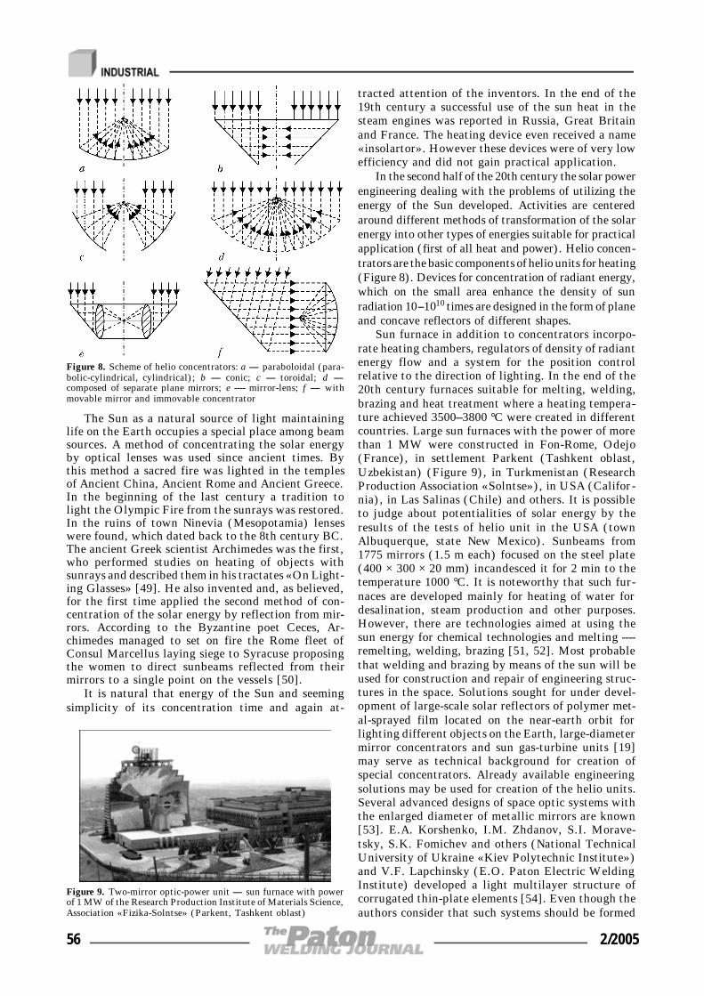
The Sun as a natural source of light maintaininglife on the Earth occupies a special place among beamsources. A method of concentrating the solar energyby optical lenses was used since ancient times. Bythis method a sacred fire was lighted in the templesof Ancient China, Ancient Rome and Ancient Greece.In the beginning of the last century a tradition tolight the Olympic Fire from the sunrays was restored.In the ruins of town Ninevia (Mesopotamia) lenseswere found, which dated back to the 8th century BC.The ancient Greek scientist Archimedes was the first,who performed studies on heating of objects withsunrays and described them in his tractates «On Light-ing Glasses» [49]. He also invented and, as believed,for the first time applied the second method of con-centration of the solar energy by reflection from mir-rors. According to the Byzantine poet Ceces, Ar-chimedes managed to set on fire the Rome fleet ofConsul Marcellus laying siege to Syracuse proposingthe women to direct sunbeams reflected from theirmirrors to a single point on the vessels [50].
It is natural that energy of the Sun and seemingsimplicity of its concentration time and again at-
tracted attention of the inventors. In the end of the19th century a successful use of the sun heat in thesteam engines was reported in Russia, Great Britainand France. The heating device even received a name«insolartor». However these devices were of very lowefficiency and did not gain practical application.
In the second half of the 20th century the solar powerengineering dealing with the problems of utilizing theenergy of the Sun developed. Activities are centeredaround different methods of transformation of the solarenergy into other types of energies suitable for practicalapplication (first of all heat and power). Helio concen-trators are the basic components of helio units for heating(Figure 8). Devices for concentration of radiant energy,which on the small area enhance the density of sunradiation 10--1010 times are designed in the form of planeand concave reflectors of different shapes.
Sun furnace in addition to concentrators incorpo-rate heating chambers, regulators of density of radiantenergy flow and a system for the position controlrelative to the direction of lighting. In the end of the20th century furnaces suitable for melting, welding,brazing and heat treatment where a heating tempera-ture achieved 3500--3800 °C were created in differentcountries. Large sun furnaces with the power of morethan 1 MW were constructed in Fon-Rome, Odejo(France), in settlement Parkent (Tashkent oblast,Uzbekistan) (Figure 9), in Turkmenistan (ResearchProduction Association «Solntse»), in USA (Califor-nia), in Las Salinas (Chile) and others. It is possibleto judge about potentialities of solar energy by theresults of the tests of helio unit in the USA (townAlbuquerque, state New Mexico). Sunbeams from1775 mirrors (1.5 m each) focused on the steel plate(400 × 300 × 20 mm) incandesced it for 2 min to thetemperature 1000 °C. It is noteworthy that such fur-naces are developed mainly for heating of water fordesalination, steam production and other purposes.However, there are technologies aimed at using thesun energy for chemical technologies and melting ----remelting, welding, brazing [51, 52]. Most probablethat welding and brazing by means of the sun will beused for construction and repair of engineering struc-tures in the space. Solutions sought for under devel-opment of large-scale solar reflectors of polymer met-al-sprayed film located on the near-earth orbit forlighting different objects on the Earth, large-diametermirror concentrators and sun gas-turbine units [19]may serve as technical background for creation ofspecial concentrators. Already available engineeringsolutions may be used for creation of the helio units.Several advanced designs of space optic systems withthe enlarged diameter of metallic mirrors are known[53]. E.A. Korshenko, I.M. Zhdanov, S.I. Morave-tsky, S.K. Fomichev and others (National TechnicalUniversity of Ukraine «Kiev Polytechnic Institute»)and V.F. Lapchinsky (E.O. Paton Electric WeldingInstitute) developed a light multilayer structure ofcorrugated thin-plate elements [54]. Even though theauthors consider that such systems should be formed
Figure 9. Two-mirror optic-power unit ---- sun furnace with powerof 1 MW of the Research Production Institute of Materials Science,Association «Fizika-Solntse» (Parkent, Tashkent oblast)
Figure 8. Scheme of helio concentrators: a ---- paraboloidal (para-bolic-cylindrical, cylindrical); b ---- conic; c ---- toroidal; d ----composed of separate plane mirrors; e ---- mirror-lens; f ---- withmovable mirror and immovable concentrator
56 2/2005

by welding (one-sided spot-welded joints) a long-standing experience for production of similar gridstructures (aviation and rocket) permits stating thatbrazing will be the most effective method of joiningfor construction of optic systems in the space [55].
CONCLUSIONS
1. Owing to inventions in the sphere of physics ofhigh energies, optics and due to development of de-vices radiating flows of electrons and light quantathe commercial units for transformation of kineticenergy of electron flows and electromagnetic radiationinto heat energy suitable for practical brazing weredeveloped in the second half of the 20th century.
2. Technological possibilities of electron-beam andoptic units: inertialessness, high concentration of en-ergy, accuracy in positioning allow effective solutionsin production of complex assemblies and structuresranging from microelectronic elements to large-scaleengineering structures in space using all structuralmetallic alloys, ceramic and other materials.
1. Petunin, I.E., Ekatova, A.S., Markova, I.Yu. (1976) Met-als science of brazing. Moscow: Metallurgiya.
2. Lashko, N.F., Lashko, S.V. (1974) Problems of theory andtechnology of brazing. Saratov: SGU.
3. Rossoshinsky, A.A., Tabelev, V.D., Kislitsyn, V.M. (1971)Pressure microwelding. Kiev: Tekhnika.
4. (1975) Reference book on brazing. Ed. by S.N. Lotsmanovet al. Moscow: Mashinostroenie.
5. Frolov, V.P., Markova, I.Yu., Eroshev, V.K. et al. (2001)Development of brazing in the 20th century. In: Brazing.Current technologies, materials, structures. Moscow: TsRDZ.
6. Lashko, N.F., Lashko, S.V. (1981) Brazing of metals. In:Welding in the USSR. Vol. 1. Moscow: Nauka.
7. Shiller, V., Gajzik, U., Pantser, Z. (1980) Electron beamtechnology. Moscow: Energiya.
8. Wyman, W.L. (1958) High-vacuum electron-beam fusionwelding. Welding J., 2, 49--53.
9. Stohr, J.A., Briola, J. (1958) Vacuum welding of metals.Welding and Metal Fabrication, 10, 366--370.
10. Olshansky, N.A. (1959) Method of vacuum electron beamwelding. Avtomatich. Svarka, 8, 3--11.
11. Movchan, B.A., Rabkin, D.M., Gurevich, S.M. et al.(1959) Some technological features of vacuum electronbeam welding. Ibid., 8, 32--33.
12. Khorunov, F.V., Malevsky, Yu.B., Nesmikh, V.S. et al.(1968) Effect of some technological parameters of welding-brazing process. Ibid., 11, 22--25.
13. Kabanov, A.N., Kafarov, A.A., Mikhajlovsky, G.A. (1967)Service characteristics of installation ELURO. Ibid., 3, 72--73.
14. Iliin, V.V., Klyujkov, A.G. (1967) Stabilized source of ac-celerating voltage for installation ELURO. Ibid., 75--76.
15. Kabanov, A.N., Zolotov, L.A. (1967) Application of instal-lation ELURO for microwelding and brazing. Ibid., 74--75.
16. Pletnev, V.M., Ryzhkov, F.N., Drozdov, M.L. et al. (1971)Electron beam brazing of needle-less injector assembly unit.Svarochn. Proizvodstvo, 4, 49--50.
17. Khorunov, V.F., Lapchinsky, V.F., Shvets, V.I. et al.(1993) Technology of vacuum brazing of aluminium alloytruss structure components. Avtomatich. Svarka, 2, 52--53.
18. Tkachenko, G.G., Radzievsky, V.I., Gartsunov, Yu.F.(2000) Autovacuum brazing of impellers of centrifugal com-pressors of 07Kh16N6 steel. In: Brazing. Toliatti: TPI.
19. Paton, B.E., Lapchinsky, V.F. (1998) Welding and relatedtechnologies in space. Kiev: Naukova Dumka.
20. Khorunov, V.F., Shvets, V.I., Bulatsev, A.R. et al. (1999)Peculiarities of formation of brazed joints of thin-wall struc-tures in space. Avtomatich. Svarka, 10, 31--38.
21. Asnis, E.A., Zabolotin, S.P., Lapchinsky, V.F. et al. (1997)Technology of repair of pipelines using the electron-beamwelding and brazing as applied to space conditions. Ibid., 8,50--53.
22. Paton, B.E., Bulatsev, A.R., Mikhajlovskaya, E.S. et al.(1998) Truss structures in orbital complexes. Ibid., 11, 5--10.
23. Laslo, T.S. (1968) Optical high-temperature furnaces. Mos-cow: Mir.
24. Born, M., Volf, E. (1973) Principles of optics. Ed. by G.P.Motulevich. Moscow: Nauka.
25. Clouder, J.R., Sudarshan, E. (1970) Principles of quantumoptics. Ed. by S.A. Akhmanov. Moscow: Mir.
26. Baranov, M.S., Kondratiev, V.A., Uglov, A.A. (1972) Ki-netics of formation of wire splice in pulse laser beam weld-ing. Fizika i Khimiya Obrab. Materialov, 5, 11--14.
27. Rykalin, N.N., Uglov, A.A., Kokora, A.N. (1975) Lasertreatment of materials. Moscow: Mashinostroenie.
28. Avramchenko, P.F., Velichko, O.A., Moravsky, V.E. (1978)Pulse laser brazing of conductors with films in microinstru-ment-making industry. Avtomatich. Svarka, 5, 24--26.
29. (1975) Joining of integrated circuit elements by laser. In:News in science and technique: Inform. commun. VINITI.Issue 14.
30. Yakubovich, O.V., Matyushkov, V.E. et al. (1981) Laserbrazing of electronic engineering items. Ibid., 4, 57--59.
31. Husner, J., Olaineck, C. (2003) Laser brazing in automo-bile production. Thyssen Krupp Techforum, 12, 60--63.
32. Vinogradov, B.A., Kharicheva, D.L., Shvajka, D.S. (2001)Modeling of thermal processes in laser brazing of ceramicswith metal. Problemy Mashinostr. i Nadyozhn. Mashin, 4,71--75.
33. Vinogradov, B.A., Kharicheva, D.L., Styopochkin, V.A. etal. (2004) Determination of typical heat zones in laser brazingof metal with ceramics. Svarochn. Proizvodstvo, 8, 23--26.
34. Saida, K., Nishimoto, K. (2003) Method of diode laser braz-ing. Welding Technology, 51(6), 92--98.
35. Dodd, E., Bilakh, Ya. (2004) Repair of blades by laser isthe technology of the future. Svarshchik, 3, 34--35.
36. Azdasht, G., Zakel, E., Reiche, H. (1996) Implementationof low power diode laser for soldering by fibre push connec-tion method. Soldering and Surface Mount Technology, 22,51--54.
37. Garashchuk, V.P., Shelyagin, V.D., Nazarenko, O.K. et al.(1997) Technological CO2-laser LT-104 of 10 kW power.Avtomatich. Svarka, 1, 36--39.
38. (1965) Electric furnaces OKB-1152 and OKB-1153 with in-frared heating. Elektrotermiya, Issue 43, 3--4.
39. Khorunov, V.F., Kuzhel, A.V., Malevsky, Yu.B. (1974)Production of brazed lamellar structures. Avtomatich.Svarka, 11, 53--56.
40. Nikiforov, G.D., Oparin, M.I., Fyodorov, S.A. (1979)Light beam welding and brazing. Manual. Moscow: Mashi-nostroenie.
41. Frolov, V.A., Mamaev, V.S., Pronin, N.S. et al. (1993)Use of light beam energy for technological purposes.Svarochn. Proizvodstvo, 4, 12--14.
42. Khorunov, V.F., Shal Dzigo. (1995) Welding and brazingof different materials using the light beam of arc xenonlamps (Review). Avtomatich. Svarka, 5, 48--52.
43. Nikiforov, G.D., Diachenko, V.V., Oparin, M.I. et al.(1969) Use of focused light energy of high-capacity xenonlamps for welding and brazing of metals. Svarochn. Proiz-vodstvo, 9, 1--3.
44. Nikiforov, G.D., Oparin, M.I., Fyodorov, S.A. (1974) Useof light heating for welding, brazing and heat treatment.Ibid., 12, 18--21.
45. Mironov, L.G., Ravaev, G.P., Petukhov, V.F. (1981) Ex-perience of application of focused light energy of arc xenonlamps for brazing of items. In: New developments in braz-ing. Kiev: PWI.
46. Takagi, M., Yamaji, T. (1995) New soldering process usinglight beam technology. Soldering and Surface Mount Tech-nology, 20, 13--20.
47. Frolov, V.A. (1998) Engineering and design features of de-velopment of welded structures using the light beam weld-ing. Svarochn. Proizvodstvo, 3, 16--20.
48. Frolov, V.A., Proshin, N.S., Fyodorov, S.A. et al. (2003)Development and improvement of light-beam welding, braz-ing and heat treatment technologies. Tekhnologiya Mashi-nostroeniya, 5, 28--29.
49. (1962) Archimedes. Treatases. Moscow: Fizmatgiz.50. Veselovsky, I.N. (1957) Archimedes. Moscow: Uchpedgiz.51. (1983) Optic infrared telescopes in the 1990s. Moscow:
Mir.52. Kornienko, A.N. Reflector. USSR author’s cert. 350614.
Int. Cl. B 23 K 27/00. Publ. 13.09.72.53. Semyonov, Yu.P. (2003) Space technologies on the thresh-
old of the centuries: results and prospects. The Paton Weld-ing J., 10/11, 21--30.
54. Zhdanov, I.M., Kononchuk, V.V., Fomichev, S.K. et al.Package for producing the multilayer structure. USSRauthor’s cert. 1684091. Int. Cl. 5 B 32 B 3/12. Publ.15.10.91.
55. Belotserkovsky, S.M., Odnovol, L.A., Safin, Yu.Z. et al.(1985) Lattice wings. Moscow: Mashinostroenie.
2/2005 57

METHOD OF SOFTWARE DEVELOPMENT USINGCONTROL GRAPHS AND LANGUAGES MEANS ISaGRAF
FOR INTELLIGENT WELDING CONTROLLERS
F.N. KISELEVSKY, V.V. DOLINENKO and D.D. TOPCHEVE.O. Paton Electric Welding Institute, NASU, Kiev, Ukraine
A new method is proposed to develop software of intelligent welding controllers, using control graphs of the states andSFC language of ISaGRAF package. An example is considered of synthesis of a child program «Arc ignition» for thearc power source controller of TIG welding CAM system.
K e y w o r d s : arc welding, automatic control, control graphs,software
This study is devoted to the problem of developmentof object-oriented systems of automatic control of arcwelding [1]. Development of the software for intel-ligent controllers of welding equipment can run intodifficulties in some cases. On the one hand, low-costrequirements are made of them, and, on the otherhand, they should implement data communicationprotocols accepted in the automated system and sup-port in real time the realization of control graphs ofthe states of the lowest level of the control program.Application of a programmed logical controller (PLC)Smart-I/O (PEP Company, Germany) for develop-ment of intelligent welding controllers can be an in-teresting solution. Unlike the traditional PLC, Smart-I/O can run programs written both using the knownprogramming languages ANSI-C and C++, and spe-cialized ISaGRAF package [2]. The latter has thefollowing advantages: use of standard programminglanguages IEC1131-3; graphic development interface;easy mastering and convenient use; built-in means forprogramming industrial networks; convenient and ef-fective debugging aids.
According to IEC1131-3 standard, developers havefive language means at their disposal: language ofsequential functional circuits (SFC); functional
block-diagrams (FBD); relay diagrams (LD); struc-tured text (ST) and instructions (IL).
PWI is working on development of a procedureof automated design of object-oriented CAM systemsfor welding, in particular, welding equipment con-trollers. Conducted investigations on development ofa formal approach for synthesis of control programsin ISaGRAF language allowed formulating a methodfor development of programs for intelligent control-lers of welding equipment. As an example, let usconsider programming of a control graph for «Arcignition» function in TIG welding of items of alu-minium alloys (Figure).
The following conventions are taken, when assign-ing the graph ribs:
Uab?:{Vab}, (1)
where Uab is the condition, written as Boolean ex-pression; Vab is the operator, which is fulfilled at thetrue value of condition Uab; a, b are the numbers ofgraph points, between which the rib is located.
chPodjig module (child process) has the followingpurpose: after receiving a command from upper levelcontroller «Welding start», perform the followingfunctions: raise the welding head to a certain distanceabove the item surface; switch on the arc power source;raise the welding currents to required values; lowerthe welding torch to item surface level; transfer con-trol to the next program module.
The structure of control program of the controlleris developed in FBD language, and child programsare in SFC and ST languages.
Developed by us formal method of conversion ofan object-oriented control graph of states into a block-diagram of SFC-program is a system of formal rules,which allow generating a SFC-program, the behav-iour of which corresponds to the initial control graphin terms of the control problem.
Rule 1. Each rib of the oriented graph is replacedby a pair of «transition--step» objects of SFC-pro-gram. «Transition» object implements Uab condi-tion, and «step» is Vab action for this rib.© F.N. KISELEVSKY, V.V. DOLINENKO and D.D. TOPCHEV, 2005
Control graph of child program «Arc ignition»
58 2/2005

Rule 2. Each graph tip is replaced by «step» blockof SFC-program.
A step should not have any inner operators. How-ever, in the case, if this tip has a rib-loop, «step»behaviour is described by «non-stored» action. Inkeeping with the terminology of SFC-program lan-guage a «non-stored» action is an operator block,which is repeatedly performed in each step of SFC-program operation, unlike «pulse» action, which isonly performed once, having reached the information«marker» of this «step» (information «marker» indi-cates an active «step»).
Rule 3. Follows from the rule of developing aSFC-program: a «transition» object should be presentbetween two «steps» of SFC-program. If two succes-sive «steps» do not have a «transition» object, itshould be added, and the content of such a «transi-tion» should be empty.
Rule 4. If several ribs oriented towards other tipsare adjacent to the graph tip, SFC-object «diver-gence» is used.
Rule 5. As SFC-program is organized in the formof vertical chains of objects, it is allowed to disruptthe graph ribs. A pair of «transition» objects is ap-plied in this case, using «unconditional transition».
SFC-program behaviour in real time is organizedas follows. A variable earlier declared with «Timer»type is zeroed, in «step» object code, for instance:
T1: = t#0 ms.
An inequality is added to the «transition» follow-ing this step, for instance:
T1>t#1s.
In this case a time delay of 1 s will be executed.
1. Kisilevsky, F.N., Dolinenko, V.V. (2001) Object-orientedprogramming of systems of welding technological processcontrol. The Paton Welding J., 6, 43--45.
2. (2000) ISaGRAF IEC1131-3 Version 3.00. In: User guide.C.J. International.
2/2005 59

THESES FOR SCIENTIFIC DEGREESI.M. Gubkin Russian State University of Oil andGas (Moscow)
Sidorenko A.V. (I.M. Gubkin Russian State Univer-sity of Oil and Gas) defended on the 12th of October2004 his thesis for a Candidate degree on the subject«Peculiarities of Repair of Elements of Units forCleaning of Gas from Acid Components».
Analysis of service conditions of units for cleaningof natural gas from acid components showed that themain causes of failure of the units were general non-uniform and pitting corrosion of metal.
It is shown that the use of high-alloy austeniticmaterials for cladding on carbon steels leads to sub-stantial macroheterogeneity of the surface and, as aresult, to its local damage. Formation of an activegalvanic element between the repaired and non-re-paired surfaces leads to fracture of the region of fusionwith base metal.
It is indicated that in environments containingboth passivating and activating agents even a smallelectrochemical heterogeneity causes an intensive pit-ting damage of the surface. As this heterogeneity isformed as a result of mixing of dissimilar base andfiller metals, taking place during cladding, it is ra-tional to use cladding consumables close in chemicalcomposition to the base metal for joints operating inthe above environments.
It is established that in the case of a comparablestate of non-metallic inclusions, the bainitic componentof structure, despite its high thermodynamic instability,provides increase in resistance to general and local cor-rosion due to higher homogeneity. The rational struc-tural composition of deposited metal, consisting mostlyof bainite (not less than 80 %), is determined.
The possibility of applying a generalised methodby N.N. Rykalin to determine main geometric parame-ters of the cladding zone, temperature-time conditionsof formation of deposited metal and parameters ofargon-arc and plasma-arc cladding is proved. Calcu-lation results are confirmed experimentally.
The field of a reasonable application of the argon-arc and plasma-arc cladding methods is identified.Unless thickness of the metal layer being restored isin excess of 2.0--2.5 mm, and the required coolingrate in a range of diffusion transformation of austeniteis more than 40 °C/s, it is possible to use plasma-arccladding. With increase in thickness of the depositedlayer and keeping to the required cooling rates of lessthan 40 °C/s, it is indicated to use electric arc clad-ding by the GMA method.
The technology for restoration of the surface ofequipment by the method of mechanised electric arccladding using metal electrode in a mixture of gases(Ar + 20 % CO2) was developed. The technology pro-vides structure of the deposited layer that containsnot less than 80 % of the bainitic component, whichis resistant to the corrosion effect by a working envi-ronment of the units for cleaning of natural gas fromacid components.
Experimental-industrial tests proved validity of theapplication of the developed technology for cladding
carbon materials to repair elements of the units forcleaning of gas from acid components. In all cases thedeposited metal has mechanical characteristics thatare not inferior to those of the base metal, and a highresistance to general non-uniform and pitting corro-sion.
The possibility of providing rational structuralcomposition and required resistance of the depositedmetal to the effect of a corrosive environment for anumber of carbon cladding consumables is shown us-ing the computer analysis.
The process instruction developed on the basis ofthe results of the work on restoration of internal sur-face of the U172 type unit for cleaning of gas fromacid components was agreed upon with the All-Rus-sian Research Institute of Gas and is recommendedfor application at the Astrakhan Gas Processing Plant.
Belarussian-Russian University (Mogilyov, Repub-lic of Belarus)
Yakubovich D.I. (Belarussian-Russian University)defended on the 16th of December 2004 the thesis fora Candidate degree on the subject «Improving Qualityof Welded Joints in Thin-Sheet Steels Sensitive toThermal Cycle through Redistribution of Heat Flowfrom a Heat Source».
The thesis analysed the effect of redistribution ofheat input into a workpiece on the process of fillingof gaps and edge displacement. Additional possibili-ties of regulating the rate of cooling of HAZ, prevent-ing formation of martensite and accompanying coldcracks through redistribution of the heat flow in elec-trode weaving are revealed for steels sensitive to weld-ing thermal cycle.
The effect of displacement of edges of the partsjoined on the welding process was studied, and themaximum permissible edge displacements and edgegaps for butt welded joints in thin metal (0.1--2.0 mm) were established. The efficiency of electrodeweaving for improving the quality of weld formationand prevention of burns-through is shown.
The expediency of using a more concentrated en-ergy source for limiting size of the weakening zone incold-worked steel in a temperature range of 1500 to400 °C and reducing the time of growth of grain nearthe weld to 2--5 s is shown.
The mechanism of cold cracking of steels sensitiveto welding thermal cycle is revealed. It consists inthe beginning of fracture under the effect of interac-tion of hydrogen atmospheres with moving disloca-tions. Methods were developed for increasing techno-logical strength through optimisation of oxidation po-tential of a shielding atmosphere.
The technology for robotic welding of steel 1 mmthick was developed, and optimal conditions wereidentified, providing sound welded joints at a weldingcurrent of 60--80 A, voltage of 17--20 V, amplitudeof 4 mm and frequency of 3 Hz. The results of studiesof butt welded joints 1.2 mm thick made in shieldinggases with electrode weaving have found commercialapplication.
60 2/2005