international maritime organization e · pdf file.1 in the new specification there should be...
TRANSCRIPT
I:\DE\45\5-2.DOC
For reasons of economy, this document is printed in a limited number. Delegates are kindly asked to bring their copies to meetings and not to request additional copies.
INTERNATIONAL MARITIME ORGANIZATION
IMO
E
SUB-COMMITTEE ON SHIP DESIGN AND EQUIPMENT 45th session Agenda item 5
DE 45/5/2
13 December 2001 Original: ENGLISH
REVISION OF RESOLUTIONS MEPC.60(33) AND A.586(14)
Report of the intersessional correspondence group on the revision
of resolutions MEPC.60(33) and A.586(14)
Part 2 - Revision of resolution A.586(14)
Submitted by the United Kingdom
SUMMARY
Executive summary:
This paper reports the outcome of the intersessional correspondence group given the task at DE 44 of considering the revision of resolution A.586(14)
Action to be taken:
Paragraph 7
Related documents:
DE 43/18, DE 44/19
1 As agreed by the Sub-Committee at its forty-fourth session, an intersessional correspondence group was established tasked with producing a revised text of resolution A.586(14) for consideration at DE 45. The terms of reference of the correspondence group regarding the revision of resolution A.586(14), as specified in DE 44/19, were:
.1 to prepare a revised text of resolution A.586(14); and
.2 to submit a report to DE 45. 2 The correspondence group consisted of Brazil, Denmark, France, Germany, Greece, Hong Kong, Japan, the Netherlands, Norway, Sweden, the United Kingdom, the United States, ICS, ICCL and ISO. The submissions of those Members that contributed is very much appreciated, however a number of delegations have reserved their position pending further discussion in any proposed working group. 3 In the annex to this report is a consolidated text incorporating the points for discussion put forward by Correspondents. For ease of reference the original text for resolution A.586(14) is utilised as a base document, with the amendments proposed and points for further discussion inserted and identified either by cross out or underline, with footnotes added at relevant points in the text.
DE 45/5/2 - 2 -
I:\DE\45\5-2.DOC
4 The Sub-Committee will recall that DE 43/18 recorded some proposals for the revision of resolution A.586(14), namely;
.1 in the new specification there should be only one category of ODME for all tankers of 150 GT and above;
.2 the ODME should be able to record position (latitude and longitude) of the oil
tanker and, as speed could be derived from position and time, an input from the ship's speed log would no longer be necessary;
.3 the accuracy requirements for the oil content meter in the ODME should be
amended to +/- 10ppm or +/- 10%, whichever is the greater; .4 type approval examination should include confirmation that the test rig has critical
dimensions in line with the manufacturers installations instructions; .5 test oils should be given more objective specifications such as the API
specification or a range based on the API characteristics such as density, viscosity and pour point; and
.6 the requirement for grab samples should be removed and that knowledge of the oil
injection rate during testing can be verified by the Administration.
5 The group considered the above proposals and some have been incorporated in the consolidated text enclosed in the annex, together with other points raised by correspondents for future discussion. 6 Notwithstanding the concerns reference the “Method for determination of oil content” now referred to the MEPC, there are several areas where a common position was not reached and it is clear that further work is required before an agreed draft specification can be submitted to the Sub-Committee. Action requested of the Sub-Committee 7 The Sub-Committee is invited to approve the report in general, and decide on how to continue with the further work required.
***

DE 45/5/2 ANNEX
I:\DE\45\5-2annex.doc
DRAFT
REVISED GUIDELINES AND SPECIFICATIONS FOR OIL DISCHARGE MONITORING AND CONTROL SYSTEMS FOR OIL TANKERS
ANNEX Part 1 Test and performance specifications for type approval of oil content meters Part 2 Specification for environmental testing for type approval of the oil content meter and the
control section of an oil discharge monitoring and control system Part 3 Documentation of approval 1 INTRODUCTION 1.1 Purpose 1.1.1 These Guidelines and Specifications contain requirements regarding the design, installation, performance and testing of oil discharge monitoring and control systems on oil tankers as required by regulation 15(3)(a) of Annex I of MARPOL 73/78. 1.1.2 The purpose of these Guidelines and Specifications is:
.1 to provide a uniform interpretation of the requirements of regulation 15(3)(a) of Annex I of MARPOL 73/78;
.2 to assist Administrations in determining appropriate design, construction and
operational parameters for oil discharge monitoring and control systems for oil tankers, hereafter referred to as “monitoring systems”, when such systems are fitted in ships flying the flag of their State;
.3 to define test and performance requirements for oil content meters and control
sections forming part of monitoring systems; .4 to define requirements for plan approval of installations and functional testing of
installed equipment; and .5 to provide guidance for the survey of installations on board.
1.1.3 These Guidelines and Specifications also apply to oil content monitoring systems used for monitoring certain category C and D oil-like noxious liquid substances carried in accordance with regulation 14 of Annex II of MARPOL 73/78. Wherever in these Guidelines and Specifications reference is made to oil being monitored, this applies likewise to such oil-like noxious liquid substances. 1.2 Applicability 1.2.1 These Revised Guidelines and Specifications apply to installations being made in oil tankers, the keels of which are laid or which are at a similar stage of construction on or after

DE 45/5/2 ANNEX Page 2
I:\DE\45\5-2annex.doc
2 October 1986. **/**/**1 The The Guidelines and Specifications adopted under resolutions A.393(A.393 (X), A.496(A.496 (XII), and MEPC.13(MEPC.13 (19) and A.586(A.586 (14) are not applicable to oil tankers to which these new Guidelines and Specifications apply. 1.2.2 Installations made in “existing” tankers as defined in regulation 1(7) before 2 October 1986, and installations made in “new” tankers as defined in regulation 1(6) of Annex I of MARPOL 73/78, and the keels of which are laid or which are at a similar stage of construction before 2 October 1986, should comply either with the requirements contained in the Guidelines and Specifications adopted under resolutions A.393(A.393 (X), A.496(A.496 (XII) and MEPC.13(MEPC.13 (19) and A.586(A.586 (14) or with the requirements contained in these Guidelines and Specifications.2 1.3 Summary of requirements 1.3.1 The approval requirements for various parts of a monitoring system as specified in these Guidelines and Specifications are summarized below:
.1 the oil content meter should be tested for type approval in accordance with the procedures described in part 1 of the Annex;
.2 the oil content meter and the control section of a monitoring system should be
subjected to the environmental tests specified in part 2 of the Annex; .3 documentation for plan approval, as specified in section 8, should be submitted to
the Administration prior to the installation of the monitoring system; .4 the component parts of the system should undergo the workshop functional tests
specified in section 7; and .5 the complete monitoring system should be surveyed in accordance with the
procedures laid down in section 10.
2 BACKGROUND 2.1 The requirements of Annex I of MARPOL 73/78 relating to oil content monitoring of oil tanker ballast and tank washing water are set out in regulation 15(3)(a), which stipulates that oil tankers of 150 tons gross tonnage and above should be equipped with an approved monitoring system and that such system should record continuously: .1 the discharge of oil in litres per nautical mile; and
.2 the total quantity of oil discharged or, alternatively, the oil content of the effluent and the rate of discharge.
In both cases, the record should be identifiable as to time and date and should be kept for at least three years.
1 Date to be inserted later 2 This text does not reflect the correct application. A new text needs to be agreed for application of the "grandfather" clause

DE 45/5/2 ANNEX
Page 3
I:\DE\45\5-2annex.doc
2.2 Regulation 15 also stipulates that the system should come into operation when there is any discharge of effluent into the sea and should be such as will ensure that any discharge of oily mixture is automatically stopped when the instantaneous rate of discharge of oil exceeds that permitted by regulation 9(1)(a). 2.3 Resolution A.445(XI) recognizes the need for early installation of oil discharge monitoring and control systems in order that operational experience may be gained. That resolution further invites the Marine Environment Protection Committee to develop guidelines for the progressive installation of monitoring systems for new and existing oil tankers. 2.4 An incentive scheme was adopted under resolution A.496(XII), specifying the standard of systems to be installed in tankers depending on their size and age. The implementation requirements in these Guidelines and Specifications conform with the requirements in that scheme as regards installations in new tankers as defined in regulation 1(6) of Annex I of MARPOL 73/78.3 2.3 Considering the anticipated reduction in the levels of marine pollution by oil following the introduction of double hull tankers with segregated ballast and the accelerated phase out of single hull tankers, the hereto requirements for the installation of Oil Discharge Monitoring Equipment may be considered less critical. It should however be noted that even on modern oil tankers there is still a requirement for an ODME to monitor the discharge of tank washings, the need to maintain the recent improvement in oil pollution prevention procedures ensuring the installation of ODME should still be considered important.4 3 DEFINITIONS 3.1 Oil discharge monitoring and control system 3.1.1 An oil discharge monitoring and control system, referred to in these Guidelines and Specifications as a “monitoring system”, is a system which monitors the discharge into the sea of oily ballast or other oil-contaminated water from the cargo tank areas and comprises the items specified in paragraph 5.1.4. 3.2 Control section 3.2.1 A control section of a monitoring system is a unit composed of the items specified in paragraph 5.1.4.7. and capable of operating either as a “control unit” or as a “computing unit” as specified in section 4. 5 3.3 Overboard discharge control 3.3.1 An overboard discharge control is a device which automatically initiates the sequence to stop the overboard discharge of the effluent in alarm conditions and prevents the discharge throughout the period the alarm condition prevails. The device may be arranged to close the overboard valves or to stop the relevant pumps, as appropriate.
3 It is submitted that clauses 2.3 and 2.4 no longer apply 4 Additional background comment emphasising the importance of ODME equipment on modern tonnage. 5 There is a proposal to delete any reference to Category B monitoring systems. This would appear to delete the requirement for "computing units" with only "control units" as per Category A monitoring systems in paragraph 4.1.1.1 envisaged. Correspondents are invited to confirm this is the intent of the Sub-Committee understanding

DE 45/5/2 ANNEX Page 4
I:\DE\45\5-2annex.doc
3.4 Starting interlock 3.4.1 A starting interlock is a facility which prevents the initiation of the opening of the discharge valve or the operation of other equivalent arrangements before the monitoring system is fully operational when use of the monitoring system is required by the Convention. 3.5 Control unit 3.5.1 A control unit is a device which receives automatic signals of: .1 oil content of the effluent; .2 flow rate of discharge; .3 ship’s speed in knots; .4 ship's position - latitude and longitude6 .5 date and time (GMT); and .65 status of the overboard discharge control. 3.5.2 The unit shall make automatic recordings of data as specified in paragraph 5.8.2. The recordings may be stored electronically 7 3.6 Computing unit 8 3.6.1 A computing unit is a device which receives automatic signals of: .1 oil content of the effluent; and .2 date and time (GMT). In addition, the computing unit should be arranged to accept manual input of: .3 status of the overboard discharge arrangement;
6 There is a proposal to ensure there is a record of the ship position during operations requiring ODME systems in operation, an interface with a GPS type of system being the preferred option given its can supply simultaneously the information in 3.5.1.3/4/5. JPN advise it should be sufficient to note the position in the LogBook. Also not all oil tankers in excess of 150GT have GPS NL note that whilst this can be achieved, "grandfather" clause need to be applied for existing tonnage 7 There is a proposal that electronic stored data may be preferred in place of a printed record, thus enabling port State control officers the opportunity to interrogate the memory with a standard interface, laptop and software. Co-ordinators comment - Notwithstanding the difficulties in establishing a standard software/protocol for all ODME manufacturers, also compatible with PC's used by all Administrations, is this not over-complicating the "recording" issue when a lot of terminals where port State control inspection take place do not allow mobile phones/laptops etc beyond the security gate. - Comments please…Little support for this proposal NL and JPN maintain a preference for the printed format 8 Correspondents to confirm to delete the option of a "computing unit"
DE 45/5/2 ANNEX
Page 5
I:\DE\45\5-2annex.doc
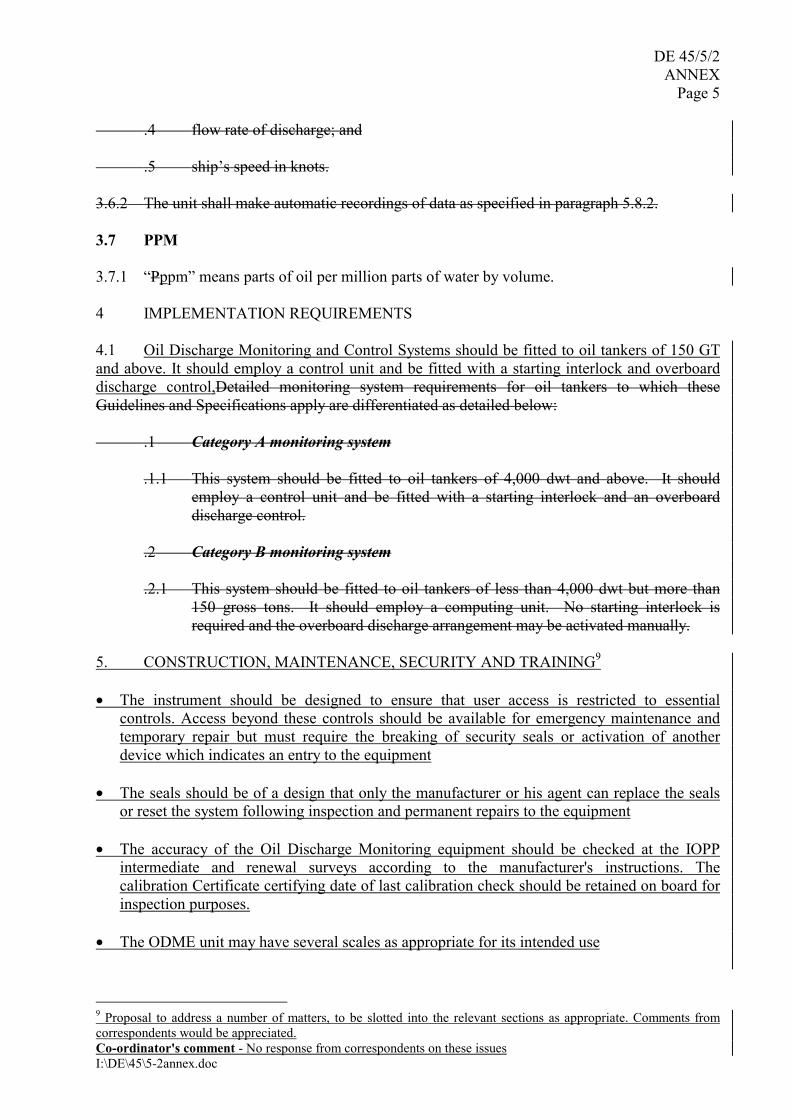
.4 flow rate of discharge; and .5 ship’s speed in knots. 3.6.2 The unit shall make automatic recordings of data as specified in paragraph 5.8.2. 3.7 PPM 3.7.1 “Pppm” means parts of oil per million parts of water by volume. 4 IMPLEMENTATION REQUIREMENTS 4.1 Oil Discharge Monitoring and Control Systems should be fitted to oil tankers of 150 GT and above. It should employ a control unit and be fitted with a starting interlock and overboard discharge control,Detailed monitoring system requirements for oil tankers to which these Guidelines and Specifications apply are differentiated as detailed below: .1 Category A monitoring system
.1.1 This system should be fitted to oil tankers of 4,000 dwt and above. It should employ a control unit and be fitted with a starting interlock and an overboard discharge control.
.2 Category B monitoring system .2.1 This system should be fitted to oil tankers of less than 4,000 dwt but more than
150 gross tons. It should employ a computing unit. No starting interlock is required and the overboard discharge arrangement may be activated manually.
5. CONSTRUCTION, MAINTENANCE, SECURITY AND TRAINING9 • The instrument should be designed to ensure that user access is restricted to essential
controls. Access beyond these controls should be available for emergency maintenance and temporary repair but must require the breaking of security seals or activation of another device which indicates an entry to the equipment
• The seals should be of a design that only the manufacturer or his agent can replace the seals
or reset the system following inspection and permanent repairs to the equipment • The accuracy of the Oil Discharge Monitoring equipment should be checked at the IOPP
intermediate and renewal surveys according to the manufacturer's instructions. The calibration Certificate certifying date of last calibration check should be retained on board for inspection purposes.
• The ODME unit may have several scales as appropriate for its intended use
9 Proposal to address a number of matters, to be slotted into the relevant sections as appropriate. Comments from correspondents would be appreciated. Co-ordinator's comment - No response from correspondents on these issues

DE 45/5/2 ANNEX Page 6
I:\DE\45\5-2annex.doc
• The recording device fitted to a meter which has more than one scale should indicate the scale which is in use
• It is recommended that simple means be provided aboard ship to check on instrument drift,
and to confirm the accuracy and repeatability of the instrument reading. • The familiarisation of the operator in the operation and maintenance of the equipment should
be documented in the ISM Code - Safety Management System • The routine maintenance of the Oil Discharge Monitoring Equipment should be clearly
defined by the manufacturer in the Operating Manual. All routine maintenance and repairs to be recorded.
5 TECHNICAL SPECIFICATIONS 5.1 Oil discharge monitoring and control system 5.1.1 The monitoring system should be capable of effectively monitoring and controlling the discharge of any effluent into the sea through those overboard discharge outlets permitted by regulation 18 which, in the opinion of the Administration, are necessary to fulfil the operational requirements of the oil tanker. 5.1.2 The discharge of dirty ballast water or other oil-contaminated water from the cargo tank areas into the sea through outlets which are not controlled by the monitoring system is an infringement of the Convention. 5.1.3 The monitoring system should function effectively under all environmental conditions which oil tankers are normally assumed to encounter, and should be designed and constructed to satisfy the specifications for environmental testing specified in part 2 of the Annex to these Guidelines and Specifications. Moreover,
.1 the system should, except as permitted for a category B system, be so designed that no discharge of dirty ballast or other oil-contaminated water from the cargo tank areas can take place unless the monitoring system is in the normal operating mode and the relevant sampling point has been selected;
.2 preferably the system should sample the effluent discharge from a minimum
number of discharge outlets and be so arranged that discharge overboard can take place via only one outlet at a time;
.3 where it is intended that more than one line be used for simultaneous discharging
purposes, one oil content meter, together with a flow meter, should be installed in each discharge line. These instruments should be connected to a common processor; and
.4 in order to avoid alarms due to short-term high oil concentration signals (spikes)
causing indications of high instantaneous rates of discharge, the short-term high ppm signal may be suppressed for a maximum of 10 seconds. Alternatively, the instantaneous rate of discharge may be continuously averaged during the
DE 45/5/2 ANNEX
Page 7
I:\DE\45\5-2annex.doc
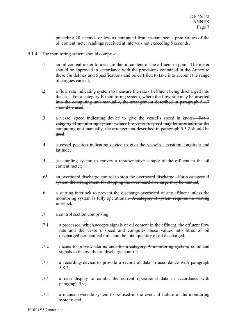
preceding 20 seconds or less as computed from instantaneous ppm values of the oil content meter readings received at intervals not exceeding 5 seconds.
5.1.4 The monitoring system should comprise:
.1 an oil content meter to measure the oil content of the effluent in ppm. The meter should be approved in accordance with the provisions contained in the Annex to these Guidelines and Specifications and be certified to take into account the range of cargoes carried;
.2 a flow rate indicating system to measure the rate of effluent being discharged into
the sea. For a category B monitoring system, where the flow rate may be inserted into the computing unit manually, the arrangement described in paragraph 5.4.7 should be used;
.3 a vessel speed indicating device to give the vessel’s speed in knots. For a
category B monitoring system, where the vessel’s speed may be inserted into the computing unit manually, the arrangement described in paragraph 5.5.2 should be used;
.4 a vessel position indicating device to give the vessel's - position longitude and
latitude; .5 a sampling system to convey a representative sample of the effluent to the oil
content meter; .65 an overboard discharge control to stop the overboard discharge. For a category B
system the arrangement for stopping the overboard discharge may be manual; .6 a starting interlock to prevent the discharge overboard of any effluent unless the
monitoring system is fully operational. A category B system requires no starting interlock;
.7 a control section comprising: .7.1 a processor, which accepts signals of oil content in the effluent, the effluent flow
rate and the vessel’s speed and computes these values into litres of oil discharged per nautical mile and the total quantity of oil discharged;
.7.2 means to provide alarms and, for a category A monitoring system, command
signals to the overboard discharge control; .7.3 a recording device to provide a record of data in accordance with paragraph
5.8.2; .7.4 a data display to exhibit the current operational data in accordance with
paragraph 5.9; .7.5 a manual override system to be used in the event of failure of the monitoring
system; and
DE 45/5/2 ANNEX Page 8
I:\DE\45\5-2annex.doc
.7.6 for a category A monitoring system, means to provide signals to the starting
interlock to prevent the discharge of any effluent before the monitoring system is fully operational.
5.1.5 Each main component of the oil content monitoring system should be fitted with a name-plate, properly identifying the component by assembly drawing number, type or model number and serial number, as appropriate. 5.1.6 If installed in a hazardous area, the electrical components of the monitoring system should meet the appropriate safety requirements∗ laid down for these areas. 5.2 Oil content meter 5.2.1 An oil content meter should satisfy the test and performance specifications contained in part 1 of the Annex to these Guidelines and Specifications and should conform with the general requirements contained in subsection 5.2. 5.2.2 The accuracy of meters designed to monitor a wide range of oil content should be such that the reading will represent the actual oil content of the sample being tested within [+/- 10%] [+ 10 ppm or + 1020%10, whichever is the greater]. The accuracy should remain within the above limit despite the presence of contaminants other than oil, such as entrained air, rust, mud and sand. 5.2.3 The meter should be designed so that it functions within the above limit when the power supply (in the form of electricity, compressed air, etc.) is varied by 10% from the value for which the meter is designed. 5.2.4 It is desirable that the reading should not be affected by the type of oil. If it is, Iit should not be necessary to calibrate the meter on board ship, but pre-set alterations in the calibration may be made in accordance with the manufacturer’s instructions. In the latter case, means should be available to check that the correct calibration has been selected for the oil in question. The accuracy of the readings should at all times remain within the limit specified in 5.2.2.11 5.2.5 The response time of the meter, as defined in paragraph 1.2.8 of part 1 of the Annex, should not exceed 20 seconds. 5.2.6 The meter may have several scales as appropriate for its intended use. The full range of the scale should not be less than 1,000 ppm. 5.2.7 The meter should have simple means to enable the ship’s crew to check the functioning of the electrical and electronic circuitry of the meter by introduction of a simulated signal corresponding approximately to half the full scale reading of the meter. It should also be possible for qualified personnel to recalibrate the meter on board the oil tanker. ∗ As specified in IEC publication 92 or its equivalent. 10 It is proposed that the accuracy of measurement in tests for all oils and Annex II substances be [+/-10%] [+/- 10ppm or +/-10%.,. whichever is the greater]. NL advise increasing the accuracy as indicated represents a challenge to industry and look for consistency between the accuracy requirements of 15ppm bilge alarms and that for ODME. UK believes the indicated improvement in accuracy is achievable. 11 NL indicates that exclusion of onboard calibration is not appropriate. Further discussions needed.

DE 45/5/2 ANNEX
Page 9
I:\DE\45\5-2annex.doc
5.2.8 The meter should, if intended to be fitted in locations where flammable atmospheres may be present, comply with the relevant safety regulations for such spaces. Any electrical equipment which is part of the meter should be placed in a non-hazardous area, or should be certified by the Administration as safe for use in a hazardous atmosphere. Any moving parts which are fitted in hazardous areas should be so arranged as to avoid the formation of static electricity. 5.2.9 The meter should not contain or use any substance of a dangerous nature, unless adequate arrangements, acceptable to the Administration, are provided to eliminate any hazard introduced thereby. 5.2.10 The meter should resist corrosion in conditions of the marine environment. 5.2.11 The meter should be constructed from materials compatible with the liquids to be tested. 5.3 Sampling system 5.3.1 Sampling points should be so located that relevant samples can be obtained from those outlets that are used for operational discharges in accordance with paragraph 5.1.1. The sampling probes located in the overboard discharge lines and the piping system connecting the sampling probes to the oil content meter should meet the requirements of this section. 5.3.2 The piping and probes should be of a material resistant to fire, corrosion, and oil and be of adequate strength, properly jointed and supported. 5.3.3 The system should have a stop-valve fitted adjacent to each probe, except that, where the probe is mounted in a cargo line, two stop-valves shall be fitted, in series, in the sample line; one of these may be the remote controlled sample selector valve. 5.3.4 Sampling probes should be arranged for easy withdrawal and should as far as practicable be mounted at an accessible location in a vertical section of the discharge line. Should it be necessary to fit sampling probes in a horizontal section of the discharge line it should be ascertained, during the installation survey, that the pipe runs full of liquid at all times during the discharge of the effluent. Sampling probes should normally penetrate inside the discharge pipe to a distance of one quarter the diameter of that pipe. 5.3.5 Means should be provided for cleaning the probes and piping system by the provision of permanent clean water flushing arrangements or an equivalent method. The design of the probes and piping should be such as to minimize their clogging by oil, oily residue, and other matter. 5.3.6 The velocity of the fluid in the piping should be such that, taking into consideration the length of the piping, the overall response time should be as short as possible between an alteration in the mixture being pumped and the alteration in the meter reading and in any case not more than 40 seconds, including the response time of the meter. 5.3.7 The location of sampling probes in relation to any point of flow diversion to a slop tank should be selected with regard to the need for sampling the oily water in the recirculation mode. 5.3.8 The arrangements for driving the sampling pump or any other pumps used in the system should have regard to the safety requirements of the space in which the pump is located. Any

DE 45/5/2 ANNEX Page 10
I:\DE\45\5-2annex.doc
bulkhead penetration between a hazardous and a non-hazardous area should be of a design approved by the Administration. 5.3.9 The flushing arrangement should be such that where necessary it can be utilized for test-running and stabilizing the oil content meter and correcting for zero setting. 5.3.10 Sample water returning to the slop tank should not be allowed to free-fall into the tank. In tankers equipped with an inert gas system a U-seal of adequate height should be arranged in the piping leading to a slop tank. 5.3.11 A valve should be provided for the manual collection of samples from the inlet piping to the meter at a point downstream of any sampling pump or at an equivalent location satisfactory to the Administration. 5.4 Flow rate indicating system 5.4.1 A flow meter for measuring the rate of discharge should be installed in a vertical section of a discharge line or in any other section of a discharge line as appropriate, so as to be always filled with the liquid being discharged. 5.4.2 A flow meter should employ an operating principle which is suitable for shipboard use and, where relevant, can be used in large diameter pipes. 5.4.3 A flow meter should be suitable for the full range of flow rates that may be encountered during normal operation. Alternatively, arrangements such as the use of two flow meters of different ranges or a restriction of the operational flow rate range may be necessary to meet this requirement. 5.4.4 The flow meter, as installed, should have an accuracy of + [15%] [10%]12, or better, of the instantaneous rate of discharge throughout the operating range for discharging the effluent. 5.4.5 Any component part of the flow meter in contact with the effluent should be of corrosion-resistant and oil-resistant material of adequate strength. 5.4.6 The design of the flow metering arrangements should have regard to the safety requirements of the space in which such metering arrangements are located. 5.4.7 In oil tankers fitted with a category B monitoring system the flow rate may be determined from the pump characteristics and the data be inserted manually into the computing unit. 5.4.8 In oil tankers fitted with a category B monitoring system where it is intended to discharge dirty ballast to the sea by gravity, as permitted by regulation 18(6)(d), means such as calibration curves should be provided to estimate the flow rate of discharge and the data should be inserted manually into the computing unit.13
12 It has been submitted that the accuracy of the measurement of the effluent overboard discharge is as important at the accuracy of the oil content meter in the ODME. With the objective of improving the overall accuracy of the ODME system NL advise that consideration should be given to tightening the tolerance to +/- 10%. 13 With Category B systems to be deleted from the specification paragraphs 5.4.7/8 and 5.5.2 are obsolete

DE 45/5/2 ANNEX Page 11
I:\DE\45\5-2annex.doc
5.5 Ship’s speed indicating system 5.5.1 The automatic speed signal required for a category A monitoring system should be obtained from the ship’s speed indicating device∗14 by means of a repeater signal. The speed information used may be either speed over the ground or speed through the water, depending upon the speed measuring equipment installed on board. 5.5.2 In oil tankers fitted with a category B monitoring system, the ship’s speed may be inserted manually into the computing unit. Such data should be obtained from the speed log or from an equivalent source. 5.6 Vessel position indicating device15 5.76 Overboard discharge control management 5.6.1 In oil tankers fitted with a category A monitoring system the overboard discharge control should be able to stop the discharge of the effluent into the sea automatically by either closing all relevant overboard discharge valves or stopping all relevant pumps. The discharge control arrangement should be fail-safe so that all effluent discharge is stopped when the monitoring system is not in operation, at alarm conditions, or when the monitoring system fails to function. 5.6.2 In oil tankers fitted with a category B monitoring system, the overboard discharge control arrangement may be activated manually. 5.7 Processor and transmitting device 5.7.1 The processor of a control section should receive signals from the oil content meter, the flow rate indicating system and the ship’s speed indicating system at time intervals not exceeding five seconds and should automatically compute the following: .1 instantaneous rate of discharge of oil in litres per nautical mile; and .2 total quantity of oil discharged during the voyage in cubic metres or litres. 5.7.2 In category B monitoring systems where the flow rate and ship’s speed may be inserted manually, the current information should be retained in the processor for use in the continuous calculation of the oil discharge rate and the total quantity of oil discharged and should be recorded at intervals specified in paragraph 5.8.3. The information currently inserted into the processor should remain visibly displayed. 5.7.3 When the limits imposed by regulation 9(1)(a)(iv) and (v) are exceeded, the processor should provide alarms and, in a category A system, provide command signals to the overboard discharge control arrangement which will cause the discharge of effluent into the sea to stop.
∗ See “Recommendation on Performance Standards for Devices to Indicate Speed and Distance” (Annex to resolution A.478(XII)). 14 The same comments on accuracy apply to the ship's speed indicating device, hence the proposal for a GPS input. Does this mean resolution A.478(XII) needs to be reviewed. 15 Text to be agreed

DE 45/5/2 ANNEX Page 12
I:\DE\45\5-2annex.doc
5.7.5 In the event of power failure the processor should retain its memory in respect to computation of the total quantity of oil discharged, time and date. A printout of data should be obtained when the monitoring system is operating with manual override, but this is not required if, when the power fails, the monitoring system activates the overboard discharge control to stop the discharge of effluent. 5.8 Recording devices16 5.8.1 The recording device of a control section should include a digital printer. The recorded parameters should be explicitly identified on the printout. The printout should be legible and should remain so once removed from the recording device and should be retained for at least three years. 5.8.2 The data to be automatically recorded should include at least the following: .1 instantaneous rate of discharge of oil (litres per nautical mile); .2 instantaneous oil content (ppm); .3 the total quantity of oil discharged (cubic metres or litres); .4 time and date (GMT); .5 ship’s speed in knots; .6 ship's position - longitude and latitude .76 effluent flow rate; .87 status of the overboard discharge control or arrangement; .98 oil type selector setting, where applicable; .109 alarm condition; .110 failure (i.e. no flow, fault, etc.); and .121 override action (i.e. manual override, flushing, calibration, etc.). Any information inserted manually should be identified on the printout as a manual input.17
16 It needs to be decided if an electronic recording device is the preferred option. NL and JPN have a preference for the present printed format 17 Manual input was required only for Category B monitoring systems

DE 45/5/2 ANNEX Page 13
I:\DE\45\5-2annex.doc
5.8.3 Data required in paragraph 5.8.2 of these Guidelines and Specifications should be printed out, as applicable, with the following minimum frequency: .1 when the discharge is started; .2 when the discharge is stopped;
.3 at intervals of not more than 10 minutes (except when the system is in stand-by mode);
.4 when an alarm condition develops; .5 when normal conditions are restored; .6 when input data are introduced;18 .7 whenever the computed rate of discharge varies by 10 litres per nautical mile; .8 when zero-setting or calibration modes are selected; and .9 on manual command.
5.8.4 The recording device should be located in a position easily accessible to the person in charge of the overboard discharge operation. 5.9 Data display 5.9.1 In addition to the recorded printout, the current data should be visibly displayed and should as a minimum contain the following: .1 instantaneous rate of discharge of oil (litres per nautical mile); .2 total quantity of oil discharged (cubic metres or litres); .3 instantaneous oil content (ppm); .4 flow rate; .5 ship’s speed; and .6 status of the overboard discharge control or arrangement. 5.9.2 The data display should be located in a position easily observed by the person in charge of the overboard discharge operation.
18 No manual input of data will be required

DE 45/5/2 ANNEX Page 14
I:\DE\45\5-2annex.doc
5.10 Manually operated alternatives 5.10.1 The alternative means of obtaining information in the event of a failure in the monitoring system should be as follows:
.1 oil content meter or sampling system: visual observation of the surface of the water adjacent to the effluent discharge;
.2 flow meter: pump discharge characteristics, etc.; .3 ship’s speed indicating device: main engine r.p.m. etc.; .4 processor: manual calculation and manual recording; and .5 overboard discharge control: manual operation of pumps and valves.
5.11 Alarm conditions resulting in the stopping of discharge 5.11.1 Audio-visual alarms should be activated for any of the following conditions and the monitoring system should be so arranged that the discharge of effluent into the sea is stopped:
.1 whenever the instantaneous rate of discharge of oil exceeds 6030 litres per nautical mile;
.2 when the total quantity of oil discharged reaches 1/30,000 of the previous cargo; .3 in the event of failure of the system’s operation, such as: .3.1 power failure; .3.2 loss of sample; .3.3 significant failure of the measuring or recording system; or .3.4 when the input of any sensor exceeds the effective capacity of the system.
5.12 Testing of alarm indicator 5.12.1 The alarm indicator of the system should be installed in the cargo control room, where provided, and/or in other places where it will attract immediate attention and action. 6 SPECIFICATIONS FOR TYPE APPROVAL OF THE OIL CONTENT METER AND
THE CONTROL SECTION OF AN OIL DISCHARGE MONITORING AND CONTROL SYSTEM
6.1 Testing requirements 6.1.1 An oil content meter should be tested for its ability to determine the oil content over a wide range of oil contents and types of oil and within the accuracy limits specified in paragraph 5.2.2. The meter, which is to be identical in all respects with the production model for which the
DE 45/5/2 ANNEX Page 15
I:\DE\45\5-2annex.doc
approval will apply, should be type-tested in accordance with the test and performance specifications contained in part 1 of the Annex to these Guidelines and Specifications. 6.1.2 An oil content meter and a control section of the monitoring system, which is to be identical in all respects with the production model for which the approval will apply, should be type-tested in accordance with the specification for environmental testing contained in part 2 of the Annex to these Guidelines and Specifications. 6.2 Approval and certification procedures 6.2.1 Oil content meters which in every respect fulfil the requirements of these Guidelines and Specifications may be approved by the Administration for fitting on board tankers. The approval should take the form of a certificate of type approval specifying the main particulars of the apparatus and any limiting conditions on its usage necessary to ensure its proper performance. Such certificate should be issued in the format shown in part 3 of the Annex to these Guidelines and Specifications. A copy of the certificate of type approval for the oil content meter should be carried aboard an oil tanker fitted with such equipment at all times. 6.2.2 A certificate of type approval should be issued for the specific application for which the oil content meter is approved, i.e. for crude oil, “black” products, “white” products, other products or applications as listed on the certificate. 6.2.3 Approved oil content meters may be accepted by other countries for use on their vessels on basis of the first trials, or after new tests carried out under the supervision of their own representatives. Should an oil content meter pass a test in one country but fail a test of a similar nature in another country, then the two countries concerned should consult one another with a view to reaching a mutually acceptable agreement. 7 WORKSHOP FUNCTIONAL TEST REQUIREMENTS 7.1 Each oil content meter and each control section of a monitoring system should be subjected to a functional test on a suitable test bench prior to delivery. The detailed programme for a functional test of such equipment should be developed by the manufacturer, taking into account the features and functions of the specific design of equipment. A completed workshop certificate including the delivery test protocol should be supplied with each unit delivered. 7.2 A functional test conducted on an oil content meter should include at least all the following operations: .1 check flow rate, pressure drop, or an equivalent parameter as appropriate; .2 check all alarm functions built into the meter; .3 check all switching functions interconnecting with other parts of the system; and
.4 check correct reading at several ppm values on all measurement scales when
operated on an oil appropriate for the application of the meter or by an equivalent method.
DE 45/5/2 ANNEX Page 16
I:\DE\45\5-2annex.doc
7.3 A functional check conducted on a control section of a monitoring system should include at least all the following operations: .1 check all alarm functions;
.2 check correct function of the signal processor and the recording equipment when simulated input signals of ppm, flow rate, and speed are varied;
.3 check that the alarm is activated when the input signals are varied so that the
discharge limits contained in regulation 9(1)(a)(iv) and (v) are exceeded; .4 check that a signal is given to the overboard discharge control when alarm
conditions are reached; and .5 check that the alarm is activated when each one of the input signals is varied to
exceed the capacity of the system.
8 PLAN APPROVAL REQUIREMENTS 8.1 Adequate documentation should be prepared well in advance of the intended installation of a monitoring system and should be submitted to the Administration for approval. The documentation to be submitted should include at least all the following:
.1 a description of the monitoring system, including identification of the category of monitoring system applicable to the oil tanker according to section 4. The description should include a diagrammatic drawing of the pumping and piping arrangements, identifying the operational outlets for dirty ballast and oil-contaminated water from the cargo tank area and compatible with the operational requirements set out in the oil tanker’s cargo and ballast handling manuals. Special considerations may have to be given to installations in oil tankers which have unusual pumping and piping arrangements;
.2 equipment manuals, supplied by manufacturers, which should contain details of
the major components of the monitoring system; .3 an operations and technical manual for the complete monitoring system which is
proposed to be installed in the oil tanker. This manual should cover the arrangements and operation of the system as a whole and should specifically describe parts of the system which are not covered by the manufacturer’s equipment manuals;
.4 the operations section of the manual should include normal operational procedures
and procedures for the discharge of oily water in the event of malfunction of the equipment;
.5 the technical section of the manual should include adequate information
(description and diagrammatic drawings of the pumping and piping arrangements of the monitoring system and electrical/electronic wiring diagrams) to enable fault finding and should include instructions for keeping a maintenance record;

DE 45/5/2 ANNEX Page 17
I:\DE\45\5-2annex.doc
.6 a technical installation specification defining, inter alia, the location and mounting of components, arrangements for maintaining the integrity of the boundary between safe and hazardous spaces and the arrangement of the sample piping, including calculation of the sample response time referred to in paragraph 5.3.6. [The installation should comply with manufacturers specific installation criteria][Specification should also include any installation criteria specific to critical dimensions in the manufacturers test rig used for Type Approval procedures in order to ensure the system on board ship, as far as practicable matches the layout and system operating conditions of the test system under which the equipment is certified] ;19
.7 a copy of the certificate of type approval for the oil content meter and technical
documentation relevant to other main components of the monitoring system; and .8 a recommended test and checkout procedure specific to the monitoring system
installed. This procedure should specify all the checks to be carried out in a functional test by the installation contractor and should provide guidance for the surveyor when carrying out the on-board survey of the monitoring system and confirming the installation reflects [the manufacturers specific installation criteria]20 [relevant critical test rig dimensions].
9 GENERAL INSTALLATION REQUIREMENTS 9.1 The on-board installation arrangements must be such that satisfactory function of the entire system is obtained and all safety regulations issued by the relevant Administration are complied with. 9.2 The installation arrangements must conform in each case with those specified and approved under the procedure for plan approval outlined in section 8. 9.3 The installation arrangements must also satisfy all relevant parts of the technical specifications in section 5 and all relevant installation instructions provided by the manufacturer of the various items of equipment and components. 10 INSTALLATION SURVEY 10.1 Verify that the following documentation is on board in a suitable format for permanent use: .1 copy of the certificate of type approval for the oil content meter;
.2 statement from the Administration, or from a laboratory authorized by the Administration, to confirm that the control section of the monitoring system has been type-tested in accordance with the specifications for environmental testing contained in part 2 of the Annex;
19 Installations on board should be similar to test rig arrangements in the critical areas where different dimensions may influence the accuracy or response of the system. NL propose alternate text relating to manufacturers specific installation criteria as opposed to test rig arrangements 20 NL propose alternate text

DE 45/5/2 ANNEX Page 18
I:\DE\45\5-2annex.doc
.3 equipment manuals for major components of the system; .4 operations and technical manual approved by the Administration, containing a
technical description of the system, operational procedures and backup procedures in case of equipment malfunction;
.5 installation specification; and .6 installation checkout procedures.
10.2 Verify the completeness of the workshop certificate for the oil content meter and the control section of the monitoring system. 10.3 Verify that the system installation has been carried out in accordance with the approved technical installation specification referred to in paragraph 8.1.6. 10.4 Verify that:
.1 the oil content meter is identical to the one for which the certificate of type approval has been issued;
.2 the installation of the oil content meter and the control section of the monitoring
system has been carried out in accordance with the manufacturer’s equipment specification; and
.3 the operational outlets are located in the positions indicated on the drawing of the
pumping and piping arrangements.
10.5 Verify that the workmanship of the installation is satisfactory and, in particular, that the bulkhead penetrations are to the relevant approved standard. 10.6 Verify that the monitoring system operates correctly when tested in accordance with the approved procedures contained in section 11 of these Guidelines and Specifications. 11 ON-BOARD FUNCTIONAL TEST AND CHECKOUT PROCEDURE 11.1 The functional test referred to in paragraph 8.1.8 should include at least all the following tests when the monitoring system is operating on water:
.1 verify correct running of pumps, absence of leakage in the sample pumping and piping system, correct functioning of remote controlled sampling valves, etc.;
.2 verify by checking flow rates or pressure drops, as appropriate, that the system
operates under correct flow conditions. This test should be repeated separately for each sampling point;
.3 verify that alarms function correctly when a malfunction occurs external to the
monitoring system, such as no sample flow, no flow meter signal, power failure, etc.;
DE 45/5/2 ANNEX Page 19
I:\DE\45\5-2annex.doc
.4 vary the simulated input signals manually while the monitoring system is operating on water and check the recordings for correct values and timing. Vary the simulated manual input signals until alarm conditions are obtained, and verify proper recordings. For a category A monitoring system Aascertain that the overboard discharge control is activating and verify that the action is being recorded;
.5 verify that normal operating condition can be reset when the value of the
instantaneous rate of discharge is reduced below 3060 litres per nautical mile; .6 activate the manual override control and verify that a recording is made and that
for a category A monitoring system the overboard discharge control can be operated;
.7 turn off the system and verify for a category A monitoring system that the
overboard discharge control cannot be operated; .8 start up the system and check the zero and gain setting for the oil content meter in
accordance with the manufacturer’s operations and technical manual; and .9 check the accuracy of theany installed flow meter, for example by pumping water
in a loop where the flow rate may be calculated from the level change in a tank. The check should be made at a flow rate of about 50% of the rated flow of the flow meter.
ANNEX
This Annex contains detailed test and performance specifications for components of an oil discharge monitoring and control system for oil tankers. The Annex is divided into three parts: Part 1 Test and performance specifications for type approval of oil content meters
Part 2 Specification for environmental testing for type approval of the oil content meter and the control section of an oil discharge monitoring and control system
Part 3 Documentation of approval
PART 1 - TEST AND PERFORMANCE SPECIFICIATIONS FOR TYPE APPROVAL OF OIL CONTENT METERS
1.1 General 1.1.1 This test and performance specification for type approval relates to oil content meters [for oil discharge monitoring and control systems for oil tankers. A meter may be tested for one of several specified applications (crude oils, black products, and white products) and the certificate
DE 45/5/2 ANNEX Page 20
I:\DE\45\5-2annex.doc
of type approval should clearly indicate the accepted application(s)].21 In addition, the electronic and measuring section of the oil content meter should be tested in accordance with the specification for environmental testing contained in part 2 of this Annex. 1.1.2 The meter being tested should satisfy all the relevant requirements contained in section 5 of these Guidelines and Specifications. 1.2 Test specifications 1.2.1 A meter designed to operate over a wide range of oil content should measure the true oil content of the sample entering the meter during each test within [+/- 10%] [+ 10 ppm22 or + 1020%], whichever is the greater], and testing should be performed in accordance with the procedures detailed in paragraphs 1.2.5 to 1.2.18 of this specification. [The accuracy should remain within these limits in the presence of contaminants other than oil and +/- 10% variations from design criteria with respect to power (electricity and compressed air)]23. 1.2.2 A diagrammatic arrangement of a test rig for evaluating the performance of oil content meters is given in Figure 1. [The diagram specifies pipe lengths, diameters and bend radii. The design and layout of the test facility should be followed exactly to ensure meters are tested in a consistent manner]24 The accuracy of the oil content meter should be determined by comparing its readings with a known flow of oil injected into a known flow of water. The grab samples25 taken should be analysed in a laboratory by the method described in paragraph 1.3 of this specification. The results of the laboratory analysis will be used for correlation and to indicate sampling and test equipment variability. The water flow rate should be adjusted so that the entire oil-water flow passes through the oil content meter, except the intermittent grab sample stream. Special care should be given to keep, continuously, a constant oil content in the water that flows into the meter. The oil and contaminant metering pumps should be adjusted to deliver a steady flow. If oil injection becomes intermittent at low concentrations, the oil may be premixed with water to provide continuous flow, if absolutely necessary. The oil injection point should be immediately upstream of the oil content meter inlet to minimize time lags caused by the sample system. [Wherever Arabian light crude oil is specified in particular tests, a similar crude oil may be substituted, provided that the oil selected is used throughout the tests.] 1.2.3 The sampling arrangement should be such that a representative homogeneous sample is obtained under all conditions of operation and under all operational proportions of oil content.
21 Proposed additional text as clarification of the application 22 It has been submitted that the current accuracy limits can allow greater discharges at high concentration, hence the proposal to apply a stricter 10% accuracy band at the upper level. Correspondents to advise which is the preferred option. On a separate issue, the effectiveness of oil discharge monitoring equipment will also be dependent on the accuracy of the flow meter and the input of speed. Correspondents are invited to comment on whether or not the Group should additionally be reviewing these components of the system 23 Proposed additional text. NL indicate a preference for +/- 10ppm or +/- 10%, whichever is the greater 24 NL advise they consider it the manufacturers responsibility to specify in their installation drawings/manual how the unit should be installed for correct operation. It is not practical to specify a standard test rig when all the manufacturers have different installation requirements. 25 There has been some discussion as to whether or not "grab samples" actually results in a representative sample being analysed, there being an opinion that grab samples in practice do not give very accurate results (grab samples on pure oils have a repeatability in the order of +/- 30% for concentrations over 100ppm, which means the accuracy is probably in the range of +/- 6%. Similarly, during the MEPC.60(33) revision discussions there was some conjecture on the pre-mixing with water if oil injection becomes intermittent at low concentrations. The Group need to consider if amendments to paragraph 1.2.2 are necessary.

DE 45/5/2 ANNEX Page 21
I:\DE\45\5-2annex.doc
The sample should be obtained [from the full flow through the meter] [at the open discharge outlet from the meter], but when this is impracticable, the sampling arrangements shown in Figure 2 should be used. Special care should be taken in collecting and preserving the sample to ensure validity of the resultant findings. 1.2.4 Should the oil content meter incorporate a filter or other device for removing solid contaminants from the mixture to be tested, such a device should be regarded as part of the oil content meter and be connected during all the tests. After completion of the contaminant, tests referred to in paragraph 1.2.10 the device used to remove solid contaminants from the mixture should be opened up and the residues inspected to ascertain that they do not contain significant amounts of oil. 1.2.5 Oil Types -26 The oil content meter should be calibrated and zeroed in accordance with the manufacturer’s instructions. It should then be tested [using the oil types specified below] [with Arabian light crude oil] at the following concentrations in ppm: 0, 15, 50, 100, 200 and at intervals of 200 up to the maximum of the meter’s highest range. A complete calibration curve should be constructed [for each of the oils under test]. Each concentration test should last for 15 minutes. After each concentration test the meter should be run on oil-free water for 15 minutes and the reading noted. [The instrument should not be re-calibrated in spite of any movement from zero.] 1.2.6 Additional concentrations may be added if required to construct a complete calibration curve for each of the following oils:27 [After calibration in the previous test, the oil content meter should be tested at concentrations of 15 ppm, 100 ppm and 90 percent of the maximum full scale with the following oils:] Type of oil Categories represented Sahara blend Density – low Viscosity – low Pour point – very low Producing country – Algeria General description – mixed base Arabian light crude Density – medium Viscosity – medium Pour point – low Producing country – Saudi Arabia General description – mixed base Nigerian medium crude Density – high Viscosity – medium Pour point – low Producing country – Nigeria General description – naphthenic
26 For 1.2.5 - 1.2.7 NL propose a more generic listing should be used, instead of names of oils, more along the lines of ISO or API specifications 27 Any revision of the Specification should include an updated review of the most commonly transported crude oils and fuel oils to see if there needs to be any amendments or expansion on the oils presently specified.

DE 45/5/2 ANNEX Page 22
I:\DE\45\5-2annex.doc
Bachaquero 17 crude Density – very high Viscosity – very high Pour point – low Producing country – Venezuela General description – asphaltic Minas crude Density – medium Viscosity – high Pour point – very high Producing country – Indonesia General description – paraffinic Residual fuel Bunker C or No. 6 fuel oil Note: Other oils covering the range of properties shown may be substituted if those shown are
unobtainable.28 The characteristics of the oil and age of sample shall be recorded. Samples used for approval
must be less than 12 months old. Following each test, the meter should be run on oil-free water for 15 minutes and the meter reading for this zero oil flow through recorded. [Should the meter reading at zero oil throughput exceed the accuracy requirement, an automatic cleaning device should be fitted to the instrument as standard] [If it is necessary to re-zero, recalibrate, dismantle or water-flush to clean the meter between tests, this fact and the time required to recalibrate or clean the meter should be noted and recorded on the certificate.]29 1.2.7 If the meter is considered suitable for “white” petroleum products, it should also be tested with the following products in a manner similar to the tests set out in paragraph 1.2.6: Automotive gasoline;30 Kerosene; and Light diesel or No. 2 fuel oil If the meter is to be considered suitable for any of the category C and D oil-like noxious liquid substances referred to in the list contained in the unified interpretations to regulation 14 of Annex II of MARPOL 73/78, it should also be tested against each such substance for which approval is required, in a manner similar to the tests set out in paragraph 1.2.6. The high shear pump shown in Figure 1 should be kept in operation at high speed during this test to assist in dissolving the appropriate fraction of the substance in the water stream.
28 There is a proposal that Oil Discharge Monitoring Systems need calibrated and tested with as similar oils as is practicably possible, with a high degree of importance attached to how to specify the oils. The Group is invited to consider if API or ISO standards should be utilised for such specifications. 29 The current specification allows re-calibration to bring the instrument back to zero. The Group need to consider if the change in emphasis on maximum accuracy at specific concentrations make such adjustments undesirable and therefore not permitted 30 Group to discuss if consideration needs to be given to a specification of the white products. Kerosene, diesel and vehicle fuels (leaded/unleaded) vary from country to country
DE 45/5/2 ANNEX Page 23
I:\DE\45\5-2annex.doc
1.2.8 Response Time - The oil content meter should be run on oil-free water and zeroed. The oil injection pump, set to 100 ppm Arabian light crude oil, should be turned on. The following response times should be recorded and included on the certificate: .1 time for first detectable reading;
.2 time to read 63 ppm (response time); and
.3 time to read 90ppm; .4 time to read 100ppm or for reading to stabilize at maximum, the value (ppm) of
which should be recorded. Following this upscale test, the oil injection pump should be turned off and the following response times should be recorded and included on the certificate: .54 time for the maximum reading to drop detectably;
.65 time to read 37 ppm (response time); and .7 time to read 10ppm .86 time for reading to stabilize at minimum, the value (ppm) of which should be
recorded. The response time of the meter, which should be taken as the average of the response time recorded to read 63 ppm and the response time recorded to read 37 ppm, should be less than 20 seconds. 1.2.9 [Fouling Tests - ]Two tests [using Arabian light crude oil] should be performed to determine the effect of oil fouling on calibration shift. The first test should be done with a 10% oil concentration and the second with a 100% oil concentration. [Both tests to be conducted using medium and heavy fuel oils]31 For the 10% oil concentration test, the meter should initially be running on oil-free water. The high capacity oil injection pump, set to give 10% oil in water, should be turned on for one minute and then turned off. For the 100% oil concentration test, the meter should be running on oil-free water. The water should be turned off and 100% oil turned on for one minute. The oil should then be turned off and the oil-free water flow resumed. Care must be taken in the design of the test equipment to ensure that the oil fouling test results are not degraded by fouling of the sample piping external to the meter. The following response times should be noted for both tests and recorded on the certificate: 31 There is a proposal to use fuel oils instead of Arabian light crude oil for these tests NL consider test with 100% Arabian Light is sufficient

DE 45/5/2 ANNEX Page 24
I:\DE\45\5-2annex.doc
.1 time for first detectable reading; .2 time to read 15ppm .3 time to read 100 ppm; .43 time for reading to go off scale on the highest range; .54 time for reading to return back on scale on the highest range; .65 time for reading to return to 100 ppm; and 7.6 time for reading to return to 15ppm . 8 time for reading to return to zero or stabilize at minimum ppm reading. [If it is necessary to dismantle or water-flush to clean the meter after each oil fouling test for it to return to a zero reading, this fact and the time required to clean and recalibrate the meter shall be noted and recorded on the certificate].[ The meter should be capable of being cleared with clean water flushing in the shortest practicable time]32 After successful completion of both oil fouling tests, a 100 ppm mixture of Arabian light crude oil should be introduced and any calibration shift noted and recorded on the certificate. 1.2.10 [Contamination Tests -] The meter should be run on contaminated water as follows: .1 the meter should be run on water, and the contaminant described in .2 of this
paragraph should be added to the water contained in the mixing tank in the concentration stated. Arabian light crude oil will be added to the mixture of water and contaminants in the following concentrations:
- 15 ppm;
- 100 ppm; and
- 300 ppm.
Any shift in the meter reading should be noted and recorded on the certificate: .2 [the contaminant should be a mixture containing not less than 270 ppm by weight
of attapulgite (see note (a)) and 30 ppm by weight of iron oxides (see note (b)). Each material should be mixed sequentially in the mixing tank to the following criteria:
.2.1 attapulgite for a period of not less than 15 minutes so that a homogeneous
suspension is formed; iron oxides for an additional period of not less than 10 minutes. The mixing process should maintain the contaminants in suspension throughout the test period;
32 Whilst there is a proposal to replace the present text, it needs to be clarified as to what is "shortest practicable time". It is suggested a maximum allowable time is specified or the revised text is deleted entirely.

DE 45/5/2 ANNEX Page 25
I:\DE\45\5-2annex.doc
.2.2 sufficient water should be available in the mixing tanks to ensure an effective
test period of not less than 15 minutes.]
[.2 Each of the contaminants listed below will be added to the water tank in the concentration given. Any shift in the meter reading should be noted and recorded on the certificate • Fresh water (if salt water is used for the test) • Very salt water - 6% common salt with tap water • Non-soluble suspended solids - approximately10ppm and 100ppm air cleaner test dust
to the following specification: - 20ppm and 30ppm iron oxide - Attapulgite at 15, 100 and 300ppm - 2.5ppm and 5ppm Black ink]33
Notes: (a) Attapulgite is a clay mineral with the chemical formula (Mg,
Al)5Si8O22(OH)44H2O and is stable in both fresh and salt water. The test contaminant should have a particle size distribution with about 30% of 10 microns or less and a maximum particle size of 100 microns.
(b) The term “iron oxides” is used to describe black ferrosoferric oxide (Fe3O4) with a
particle size distribution of which 90% is less than 10 microns, the remainder having a maximum particle size of 100 microns.
(c) The air cleaner test should meet the following specification Particle size in microns Percentage of total weight 3 - 5 35
7-10 20 14-20 15 35-40 20 70-80 10 The percentage weight may vary by no more than 2%. The actual concentration must be recorded
1.2.11 The meter should be run on water with air entrainment as follows: .1 Air should be injected into the test circuit immediately before the sample pump or,
in the absence of such pump, immediately before any conditioning unit used to
33 Group need to decide if the existing contaminant test is to be amended. Alternate text introduced for discussion although it is accepted the text is not complete with further consideration to be given to (i) how is the proposed test to be performed (ii) are all contaminants mixed together or are they added at the same time (iii) how long is each test unit run for each contaminant. NL considers that with the presence of attapulgite clay in he sample the need for air cleaner dust is not require. Black ink need not be considered, as the black iron oxide is much more representative of actual operational conditions. The term "salt water" is preferable to the term "sea water"
DE 45/5/2 ANNEX Page 26
I:\DE\45\5-2annex.doc
prepare the mixture for measurement. Injection should be by needle having an orifice dimension not exceeding 0.5 mm in diameter arranged in line with the sample flow. The quantity of air injected should be 1% of the designated flow rate of the sample pump or conditioning unit at the point of injection. Air should be delivered to the system by direct injection or pump via a suitable measuring device designed to permit a constant controllable flow rate within + 10% of the required rate of injection for an uninterrupted effective test period of not less than 15 minutes.
.2 Arabian light crude oil should be added to this mixture of water and air in the
following concentrations:
- 15 ppm;
- 100 ppm; and
- 300 ppm. Any shift in the meter reading should be recorded on the certificate. 1.2.12 [Oil Particle Size - Shear Pump Test -] The meter should be run on a mixture of water and Arabian light crude oil of 100 ppm. The high shear pump, shown in Figure 1, should be run at various speeds to provide a range of oil particle size to the meter and on completion of this test the pump should be stopped. Any effect of particle size on the meter reading should be noted and recorded on the certificate. The purpose of this test is to demonstrate that the meter’s accuracy is not significantly affected by the oil droplet size or by the degree of oil and water mixing. 1.2.13 The meter should be run on a mixture of water and Arabian light crude oil of 100 ppm. The water temperature should initially be set at 10oC and then at 65oC. If the manufacturer’s specification lists an operating maximum water temperature of less than 65oC, the meter should be run at that maximum temperature and this fact, together with any effect of water temperature on the meter reading, should be recorded on the certificate. 1.2.14 The meter should be run on a mixture of water and Arabian light crude oil of 100 ppm. The water pressure or flow rate of the mixture should be adjusted from one-half normal, to normal and to twice normal. Any effect of these changes on the meter reading should be recorded on the certificate. This test may require modification, depending on the flow characteristics of the meter. 1.2.15 [Calibration Drift Tests -] The meter should run on a mixture of water and Arabian light crude oil of 100 ppm. The water and oil injection pumps should be shut off and the meter left on with no other changes made. After eight hours, the water and the oil injection pumps should be turned on and set to provide a mixture of 100 ppm. The meter readings before and after each test and any damage to the meter should be recorded on the certificate. This test also determines the proper functioning of the low flow shut-off and alarm. 1.2.16 The meter should be run on a mixture of water and Arabian light crude oil of 100 ppm. The supply voltage should be increased to 110% of the nominal value for one hour and then
DE 45/5/2 ANNEX Page 27
I:\DE\45\5-2annex.doc
reduced to 90% of the nominal value for one hour. Any effect on meter performance should be recorded on the certificate. If the operation of the meter requires any utilities besides electricity, it should be tested with these utilities at 110% and 90% of the design figures. 1.2.17 The meter should be calibrated and zeroed in accordance with the procedures in the manufacturer’s instructions manual. A mixture of water and Arabian light crude oil of 100 ppm should be run through the meter for eight hours and any calibration drift recorded on the certificate. Following this, the meter should be run on oil-free water and any zero drift recorded on the certificate. 1.2.18 The meter should be shut down and de-energized for one week. It should be turned on and started in accordance with the manufacturer’s instructions. After the suggested warm-up and calibration procedures, the meter should be run for a period of eight hours, operating alternatively for one hour on a mixture of water and Arabian light crude oil of 100 ppm and for one hour on oil-free water. After each step in the operation, any zero or span drift should be recorded on the certificate. The total time required to perform the manufacturer’s suggested warm-up and calibration should also be recorded on the certificate. 1.2.19 [Reporting of Test Results -]A specification of the instrument concerned and a diagrammatic presentation of the test arrangements should be provided to the Administration by the manufacturer when applying for type approval and the following data should be reported in the international metric system of units: .1 types and properties of oils used in the tests; .2 details of contaminants used, in the form, for example, of a supplier’s certificate
or laboratory test protocol; and .3 results of tests and analysis of grab samples. [The recommendations of the manufacturer of the oil content meter concerning the choice and application of cleansing agents used for cleaning purpose should be recorded in the appendix to the type approval certificate]34
34 Is the use of detergents a problem with oil discharge monitoring equipment. NL indicate that if a solution or agent is used for cleaning purposes this should be listed on the type approval certificate, as it is an inherent part of correct monitor performance according to the tests.
DE 45/5/2 ANNEX Page 28
I:\DE\45\5-2annex.doc
Figure 1 – Test Rig
(TO BE INSERTED) The size of the mixing tank should be specified so as to allow a minimum “once through” effective test period of 15 minutes. Adequate arrangements should be made for in-tank mixing or recycling to ensure a homogeneous mixture.
Figure 2 – Alternative sampling arrangement in test rig
(TO BE INSERTED)
1.3 Method for the determination of oil content35 1.3.1 Scope and application .1 The method includes the measurement of most light oil fractions, although some
loss of volatile components will occur during extraction. .2 The method has a nominal working range from 2 to 8o mg/l. The lower level of
detection can be improved to 0.1 mg/l by using longer path-length cells. The upper limit of the method can be extended at least to 1,000 mg/l by preparing dilutions of the sample extract.
1.3.2 Summary of method .1 The sample is acidified to a low pH value and extracted with two volumes of
carbon tetrachloride. The oil content is determined by comparison of the infrared absorbances of the sample extract against known concentrations of the appropriate reference oil. Other suitable non-infrared active solvents may be used if preferred.
35 This subject has been discussed at some length during the Group discussion on revision of MEPC.60(33). NL have proposed the whole description of the gas chromatography test method for determining oil content in water can be replaced by a simple reference to ISO 9377-2(Dec 2000).
DE 45/5/2 ANNEX Page 29
I:\DE\45\5-2annex.doc
1.3.3 Sampling and storage .1 A representative sample of 1 litre volume is collected in a narrow-necked glass
bottle with a pressure-sealing cap. Unless the sample will be extracted on the day of collection, it is preserved by adding 5 ml hydrochloric acid (HCl) (see 1.3.5.1).
.2 The collection of composite sample is impractical, as losses of oily matter will
occur on sampling equipment. Individual portions collected at prescribed time intervals must therefore be analysed separately to obtain the average concentration over an extended period.
1.3.4 Apparatus .1 Separatory funnel, 1,000 ml volume, with Teflon stopcock; .2 Infrared spectrophotometer; .3 Cells, 5 mm path-length, sodium chloride or infrared grade quartz with a
minimum of 80% transmittance at 2,930 cm-1. The 5 mm path-length is recommended as being convenient for monitoring levels normally encountered. Longer path-lengths may be used;
.4 Filter paper, medium grade, 12.5 cm. 1.3.5 Reagents .1 Hydrochloric acid, HCl 1:1. Mix equal amounts of concentrated HCl and distilled
water; .2 Sodium chloride, NaCl reagent grade; .3 Carbon tetrachloride, CCl4 reagent grade; .4 Oil reference: oil collected from the source at the same time as the sample was
collected; .5 Stock reference standard (3 mg/ml): accurately weigh about 0.30 g of reference
oil (1.3.5.4.) into a tarred 100 ml volumetric flask and dilute to volume with carbon tetrachloride;
.6 Calibration standards: prepare a serious of dilutions by pipetting volumes of stock
reference standard into 100 ml volumetric flasks and diluting to volume with carbon tetrachloride. A convenient series of volumes if 5, 10, 15, 20 and 25 ml of stock solution. Calculate the exact concentrations of the dilutions in milligrams per 100 ml solution from the weighing above (1.3.5.5.).
1.3.6 Extraction .1 If the sample was not acidified at the time of collection, add 5 ml hydrochloric
acid (1.3.5.1) to the sample bottle. After mixing the sample, check the pH value

DE 45/5/2 ANNEX Page 30
I:\DE\45\5-2annex.doc
by touching pH-sensitive paper to the cap to ensure that the pH is 2 or lower. Add more acid if necessary.
.2 Pour the sample into a separatory funnel and add 5 g of sodium chloride. .3 Add 50 ml carbon tetrachloride to the sample bottle. Cap tightly and thoroughly
shake the bottle to rinse the inside and cap. Transfer the solvent into the separatory funnel and extract by shaking vigorously for two minutes. Allow the layers to separate.
.4 Drain the solvent layer through a funnel containing solvent-moistened filter paper
into a 100 ml volumetric flask. .5 Repeat steps .3 and .4 above with an additional 50 ml portion of fresh solvent;
combine all solvent in the volumetric flask. .6 Rinse the tip of the separatory funnel, filter paper and funnel with small portions
of carbon tetrachloride and collect the rinsings in the volumetric flask. Adjust the extract volume up to 100 ml and stopper the flask. Mix well.
.7 Drain the water layer into a 1,000 ml graduated cylinder and estimate the sample
volume to the nearest 5 ml. 1.3.7 Infrared spectroscopy .1 Prepare the infrared spectrophotometer according to the manufacturer’s
instructions. .2 Rinse a cell with two volumes of the solution to be measured, then completely fill
the cell with solution. Place a matched cell containing carbon tetrachloride in the reference beam.
.3 Scan samples and standards from 3,200 cm-1 to 2,700 cm-1. Note 1: Single beam and non-scanning spectrophotometers can be used for this
test. Follow the manufacturer’s instructions and measure the absorbance directly at or near 2,930 cm-1.
.4 Construct a straight baseline under the hydrocarbon band as illustrated in Figure 3.
If the scan is recorded on absorbance paper, read the absorbance of the peak maximum at 2,930 cm-1 and subtract the absorbance of the baseline at that point. If the scan is recorded on transmittance paper, the net absorbance is:
log10 % T (baseline)_______ %T (peak maximum)
.5 Prepare a calibration plot of net absorbance in relation to milligrams per 100 ml oil using the response of the standards.

DE 45/5/2 ANNEX Page 31
I:\DE\45\5-2annex.doc
Note 2: The oil concentration may be plotted as a percentage of stock standard. When this procedure is used, the concentration of the stock standard must be used in the calculations (see. 1.3.8.2).
.6 If the net absorbance of a sample exceeds 0.8 or the linear range of the instrument
as determined by the calibration plot, prepare a dilution of the sample by pipetting an appropriate volume of the extract into a volumetric flask and diluting to volume. If the absorbance is less than 0.1, more accurate results can be obtained by using a longer path-length cell.
1.3.8 Calculations .1 Use the calibration plot to calculate the milligrams of oil in each 100 ml of sample
extract or dilution. .2 Calculate the oil content in the sample using the formula: milligrams per litre of oil = R x D x 1000 V where: R = milligrams of oil in 100 ml solution (determined from calibration plot) D = extract dilution factor, if used (1.3.7.6) V = volume of sample, in millilitres (1.3.6.7). .3 Report results to two significant figures for levels below 100 mg/l. Note 3: For quality control, a reagent blank should be carried through each step of
the procedure.
.4 For purposes of comparison with meter records, the results should also be presented in parts per million (volume/volume) with due allowance for the relative density of the oil.
DE 45/5/2 ANNEX Page 32
I:\DE\45\5-2annex.doc
Figure 3 – Spectrum illustrating baseline construction
(TO BE INSERTED)
DE 45/5/2 ANNEX Page 33
I:\DE\45\5-2annex.doc
PART 2 – SPECIFICATION FOR ENVIRONMENTAL TESTING FOR TYPE APPROVAL OF THE OIL CONTENT METER AND THE CONTROL SECTION OF AN OIL DISCHARGE MONITORING AND CONTROL SYSTEM
2.1 General The specification for environmental testing for type approval relates to the electronic section of the oil content meter and the control section of a monitoring and control system. A control section may be an independent unit or be combined with the electronic part of the oil content meter. The equipment tested should comply with all the relevant requirements contained in section 5 of the Guidelines and Specifications. 2.2 Test specifications 2.2.1 Testing requirements The [electrical and] electronic section of the oil content meter and the control section of the monitoring system in the standard production configuration should be subjected to the programme of environmental tests set out in this specification at a laboratory approved for the purpose by the Administration or by the competent authority of the manufacturer’s home country. A copy of the environmental test document, in a format similar to that specified in paragraph 3.2 of this specification, should be submitted to the Administration by the manufacturer together with the application for type approval. 2.2.2 Test specification details Equipment should operate satisfactorily on completion of each of the following environmental tests and continue to measure oil concentration within the prescribed accuracy limits whilst being subjected to the following tests:36 .1 Vibration tests .1.1 a search should be made for resonance over the following range of frequency and
amplitude or acceleration: .1.1.1 2 to 13.3 Hz with an amplitude of + 1 mm; and 1.1.2 13.2 to 80 Hz with an acceleration of + 0.7 g. This search should be made in each of the three planes at a rate sufficiently low to
permit detection of resonance;
36 It is noted the present text calls for satisfactory operation on completion of each of the environmental tests, which in effect is to see if it can withstand the environmental test without failing or falling to pieces. It needs to be decided if the intent of the tests is to ensure continued satisfactory operation during the environmental tests. Co-ordinators comment - There is support for the proposal the electronic and measuring section of the ODME should also be included on the vibration test. NL however point out there needs to be consistency with the similar clause in MEPC.60(33)

DE 45/5/2 ANNEX Page 34
I:\DE\45\5-2annex.doc
.1.2 the equipment should be vibrated in the planes at each major resonant frequency for a period of two hours;
.1.3 if there is no resonant frequency, the equipment should be vibrated in each of the
plans at 30 Hz with an acceleration of + 0.7 g for a period of two hours; .1.4 after completion of the tests specified in .1.2 or .1.3 of this paragraph a search
should again be made for resonance and there should be no significant change in the vibration pattern.
.2 Temperature tests .2.1 Equipment that may be installed in exposed areas on the open deck or in an
enclosed space not environmentally controlled should be subjected, for a period of not less than two hours, to:
.2.1.1 a low temperature test at –25oC; .2.1.2 a high temperature test at 55 oC. .2.2 Equipment that may be installed in an enclosed space that is environmentally
controlled including an engine-room, should be subjected, for a period of not less than two hours, to:
.2.2.1 a low temperature test at 0oC; .2.2.2 a high temperature test at 55oC. At the end of each of the tests referred to in this subparagraph above, the
equipment should be switched on and it should function normally under the test conditions.
.3 Humidity tests .3.1 Equipment should be left switched off for a period of two hours at a temperature
of 55 oC in an atmosphere with a relevant humidity of 90%. At the end of this period, the equipment should be switched on and should operate satisfactorily for one hour.
.4 Tests for protection against heavy seas .4.1 Equipment that may be installed in exposed areas on the open deck shall be
subjected to tests for protection against heavy seas in accordance with lP 56 of IEC publication 529 or its equivalent.
.5 Fluctuation in power supply .5.1 Equipment should operate satisfactorily with:

DE 45/5/2 ANNEX Page 35
I:\DE\45\5-2annex.doc
.5.1.1 a voltage variation of + 10% together with a simultaneous frequency variation of + 5%;
.5.1.2 a transient voltage of + 20% together with a simultaneous frequency transient of
+ 10%, with a transient recovery time of three seconds. .6 Inclination test .6.1 Equipment should operate satisfactorily at angles of inclination up to 22.5oC in
any plane from the normal operating position and should withstand the shock of rapid movement between each plane and continue to operate satisfactorily.37
.7 Reliability of electrical and electronic equipment .7.1 The electrical and electronic components of the equipment should be of a quality
guaranteed by the manufacturer and suitable for their intended purpose. PART 3 – DOCUMENTATION OF APPROVAL 3.1 Certificate of type approval for oil content meters 3.1.1 Satisfactory compliance with all the test requirements enumerated in part 1 of this Annex should be shown in the certificate of type approval issued by the Administration in the format specified in paragraph 3.1.2 below. An Administration may issue a certificate of type approval based on separate testing or on testing already carried out under supervision by another Administration. 3.1.2 A certificate of type approval should be in the format shown in the appendix to this Annex. The certificate should identify the type and model of the oil content meter to which it applies and identify equipment assembly drawings, duly dated. Each drawing should bear the model specification numbers or equivalent identification details. The certificate should include the full performance test protocol on which it is based. If a certificate of type approval is issued by an Administration based on a certificate previously issued by another Administration, the certificate should identify the Administration which conducted the tests on the oil content meter and a copy of the original test should be attached to it. 3.2 Format of environmental test protocol 3.2.1 Satisfactory compliance with the environmental tests laid down in these Guidelines and Specifications, where applicable, should be shown on the environmental test protocol issued by the testing laboratory. The protocol should include at least the following details: .1 identification of the equipment by type and drawing number, duly dated; 37 The operation at an angle of 22.5 degrees does not represent the normal operating conditions on board a vessel. What is significant is the equipment's ability to withstand a rolling and pitching motion with shock loading at the end of each roll. The Group should consider if there is a need to specify angular acceleration and deceleration given the equipment may react differently if a roll takes say 10 seconds or 2 seconds. Co-ordinators comment - There would appear to be no support for the addition of "change in direction" load forces to the inclination tests, NL submitting such equipment would be expensive and in any case there needs to be consistency with the similar clause in MEPC.60(33)
DE 45/5/2 ANNEX Page 36
I:\DE\45\5-2annex.doc
.2 a statement of the tests conducted on the equipment, including the results thereof. 3.2.2 The environmental test protocol should be endorsed by either the Administration or a competent authority of the manufacturer’s home country to confirm that the laboratory is approved to conduct such tests. The protocol should also be signed and dated by the person in charge of the laboratory.

DE 45/5/2 ANNEX Page 37
I:\DE\45\5-2annex.doc
APPENDIX38
(10 PAGES TO BE INSERTED)
____________
38 The Group needs to decide what amendments to the Certificate of Type Approval for the Oil Discharge Monitoring Equipment. Comments please…