international journal on public works, ports & waterways ... · connecting the said...
TRANSCRIPT
International Journal on Public Works, Ports & Waterways DevelopmentsNumber 82 • March 2001
International Association of Dredging Companies
Terra et Aqua – Number 82 – March 2001
Terra et Aqua is published quarterly by the IADC, The International Association of Dredging Companies.The journal is available on request to individuals or organisations with a professional interest in thedevelopment of ports and waterways, and in particular, the associated dredging work.The name Terra et Aqua is a registered trademark.
EditorMarsha R. Cohen
Editorial Advisory CommitteeH.A.J. Fiers, Chairman P.J.A. Hamburger H.W.J. PoieszH.L.H. Smink R. Vidal Martin P.G. RolandK. de Groot F.A. Minderhoud H. Cami
IADC Board of DirectorsR. van Gelder, President O. Nakagome, Vice President C. van Meerbeeck, TreasurerP.G. Roland M. Montevecchi G. VandewalleD. Eicke J.J. Koeman
Please address inquiries to the editor.Articles in Terra et Aqua do not necessarily reflect the opinion of the IADC Board or of individual members.
© 2000 IADC, The NetherlandsAll rights reserved. Electronic storage, reprinting or abstracting of the contents is allowed for non-commercial purposes with permission of the publisher.
ISSN 0376-6411
Typesetting and printing by Opmeer Drukkerij bv, The Hague, The Netherlands.
Front cover:
Drilling holes to blast rock in Mangalore: This necessitated extreme accuracy and extensive safetymeasures, including pre-warnings and vibration monitoring (see page 8).
IADCP.J.A. Hamburger, Secretary GeneralDuinweg 212585 JV The Hague, The NetherlandsTel. 31 (70) 352 3334, Fax 31 (70) 351 2654E-mail: [email protected]://www.iadc-dredging.com International Association of Dredging Companies

2 Editorial
3 Isoviscs as Useful Parameters for Describing Sedimentation
Wolfgang Dasch and Rewert Wurpts
A newly developed procedure to determine the nautical horizon in a typical Fluid-Mud Region is compared with more conventional procedures.
8 Capital Dredging at New Mangalore Port
M.M. Kamath
The third stage in the development of one of India’s major ports included rock dredgingusing underwater drilling and blasting.
20 Kazakhstan, Offshore Exploration in the Caspian Sea
Carol Granneman and Arjan Goris
The real challenges of building underwater berms in the Caspian Sea were the sensitiveenvironment, a harsh climate, complex local regulations and deep cultural differences.
29 Environmental Aspects of Dredging; Guide7: Frameworks, Philosophies and the Future
This seventh and final volume in the IADC/CEDA series sums up the previous guides,discussing points otherwise overlooked or unresolved. It also contains two indices, by subject and place name, of the entire series.
30 Books/Periodicals Reviewed
The proceedings of an ICE technical conference on coastal management and the biannual magazine, Port Technology International, are examined.
32 Seminars/Conferences/Events
WODCON XVI is upon us, as is a Call for Papers for the PIANC conference in Australia in 2002. Other exhibits worldwide are plentiful.
Terra et Aqua – Number 82 – March 2001
CO N T E N T S
Terra et Aqua – Number 82 – March 2001
2
EDITORIAL
First on the order of business is to thank you, our readers, for your enthusiasticresponse to our request for updated information. As you may recall, the Decemberissue of Terra et Aqua contained a reader’s response form – and your response wasoverwhelming. The consequences of this are twofold: number one, it means thatthose who wish to continue to receive Terra will be certain to get it at the correctaddress; secondly, it confirms to us that our readers continue to find Terra a worth-while read. As promised, the earliest respondents have already been sent the firstsix Guides in the Environmental Aspects of Dredging Series. Guide 7, Frame-works, Philosophies and the Future, will be published this month and posted tothem immediately. This last volume also contains two indices of the whole series,by subject and by place, making it an invaluable conclusion to the series. Those ofyou who would like to order the series (or individual Guides) can do so via thepublication form attached in the centerfold.
As dredging activities increase in size and stature, IADC companies find them-selves involved with more and more capital dredging projects, as well as with theoffshore industry, often in countries far from their home shores. Our articlesreflect this variety: for instance, the capital dredging development of the NewMangalore Port on the west coast of India (see page 8) and the work being done inKazakhstan (see page 20), where offshore exploration of the Caspian Seademands specific dredging skills. In these localities IADC members often providean extra level of technical knowledge and an increased concern for safety andadherence to internationally accepted standards, which make the differencebetween just a job and a long-lasting achievement.
Heading further east, the IADC is happy to be co-sponsoring WODCON XVI,taking place April 2-5 in Kuala Lumpur, Malaysia. The significance of the Asianmarket continues to grow, and hopefully many people in the industry from outsidethe region will take this opportunity to see firsthand some of the importantdredging developments there – as well as to enjoy Asian hospitality. The IADCAnnual Award for a paper by a younger author will also be presented at theWODCON. Certainly the theme of the Congress – “Dredging for Prosperity,Achieving Social and Economic Benefits” – echoes our own underlying goals.
Robert van Gelder President, IADC Board of Directors
Abstract
To enable better judgement of the sludge situation inthe outer harbour of Emden, a series of measurementswere carried out in 1999. In this connection both anewly developed procedure to determine the nauticalhorizon in this typical Fluid-Mud Region and the moreconventional “classical” procedures to determine anddescribe the density/consistency-relationship and theyield stress of these layers were applied. The firstresults of this investigation are described here andmethods will be discussed of how these “new”procedures could be combined with the “classical”ones.
Introduction
In order to determine the position of the nauticalhorizon, rheological data are parameters of crucialimportance as far as the hydrological characteristics ofthe water to be evaluated are concerned. Ideally itwould be most desirable to obtain complete rheologicalcuts through the area to be explored and this ideally byapplying “remote sensing” methods.
The interpretation of these parameters used for thedetermination of a nautical horizon has been carried outin the harbour of Emden for eight years with greatsuccess; since 1999 the navigability of the Europoort inRotterdam has been determined by the application of avery similar method.
To enable better judgement of the sludge situation inthe outer harbour of Emden a series of measurementswas carried out in 1999. In this connection both anewly developed procedure to determine the nauticalhorizon in this typical Fluid-Mud Region and the moreconventional “classical” procedures to determine anddescribe the density/consistency-relationship and theyield-stress of these layers were applied.
Isoviscs as Useful Parameters for Describing Sedimentation
Wolfgang Dasch and Rewert Wurpts
Isoviscs as UsefulParameters forDescribing Sedimentation
3
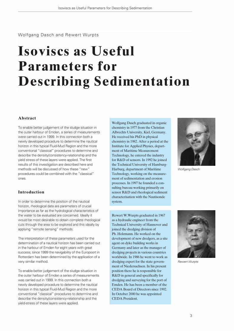
Wolfgang Dasch graduated in organicchemistry in 1977 from the ChristianAlbrechts University, Kiel, Germany.He received his PhD in physicalchemistry in 1982. After a period at theInstitute for Applied Physics, depart-ment of Maritime MeasurementTechnology, he entered the industryfor R&D of sensors. In 1992 he joinedthe Technical University of Hamburg-Harburg, department of MaritimeTechnology, working on the measure-ment of sedimentation and erosionprocesses. In 1997 he founded a con-sulting bureau working primarily onsensor R&D and rheological sedimentcharacterisation with the Nautisondesystem.
Wolfgang Dasch
Rewert Wurpts
Rewert W.Wurpts graduated in 1967as a hydraulic engineer from theTechnical University of Hannover andjoined the dredging division of Ph. Holzmann. He worked on thedevelopment of new dredgers, as a siteagent on dyke building works inGermany and later as the manager ofdredging projects in various countriesworldwide. In 1986 he went to work asdredging expert for the state govern-ment of Niedersachsen. In his presentposition there he is responsible forR&D in general and specifically fordredging and surveying for the port ofEmden. He has been a member of theCEDA Board of Directors since 1992.In October 2000 he was appointedCEDA President.

IN-SITU INVESTIGATIONS
In order to determine the position of the nauticalhorizon, rheological data are parameters of crucialimportance as far as the hydrological characteristics ofthe water to be evaluated are concerned (refs.1,2,3). Ideally it would be most desirable to obtain completerheological cuts through the area to be explored andthis ideally by applying “remote sensing” methods.
Amongst the quantities to be measured primarily arerheological parameters and here above all flow limitsand viscosities (ref. 4). The interpretation of theseparameters used for the determination of a nauticalhorizon has already been carried out in the harbour ofEmden for eight years with great success (ref. 5); since1999 the navigability of the Europoort in Rotterdam hasbeen determined by the application of a very similarmethod.
Surprisingly enough, many harbour authorities todaystill use turbine meters with wingprobes as a laboratorymethod in order to determine the parameters of theshearing forces of sludge layers in the harbour. Theundrained yield stress Cu thus obtained refers to allgrounds from soft to stiff, but it does not refer to fluid
mud and/or sludges. Using wingprobes for the determi-nation of Bingham media yield stress, there is a risk ofobtaining errors of dimensions amounting to up to onepower of ten (!). Up to now, however, the constructionof profiling measuring sensors measuring yield stresshas not been possible.
However, recently developed methods allow theapplication of profiling measurements of the mediumviscosity in situ covering the entire water column (refs.6,7,8). Kerckaert and in 1985 Malherbe showed how toapply viscosity data in order to determine the nauticaldepth (ref. 9). This, however, owing to thetechnological standards at that time, was proved byresults stemming from laboratory experiments.
In connection with the present investigations, theNautisonde system was used (refs.1,8). The profilesthus obtained permitted a visualisation in the form of“rheological cuts” through the area to be explored.The relationship to data obtained from measurementprocedures determining the yield-stress will bedescribed below.
Nautisonde system of measurementBy slowly lowering the Nautisonde probe (Figure 1) intothe system water column – suspension – sediment arheological profile is obtained. Figure 2 plots two ofthese rheological profiles at a position 1090 m from theNesserland lock in the outer harbour of Emden atvarious times (i.e. various silting-up situations) withinthe campaign in 1999. The Nautisonde probepenetrates the sediment by itself due to a mass ofapproximately 23 kg.
Four important rheologic regions are subsequentlymeasured: – first, the water column; – second, a layer of sediment suspension showing
Newtonian behaviour whilst < 3 Pa˙ s (the so-called black water);
– third, the more-or-less slowly consolidating sediment layer which is mostly the object of dredging procedures (the typical fluid mud at about3 Pa˙ s < < 20 Pa˙ s); and
– fourth, the strong consolidated (non-navigable)lower sediment layer usually not reached by dredging activities.
Taking the depth correlated to preset viscosity-limits of = 1, 2, 5 and 10 Pa˙ s obtained by measuring theviscosity profiles, so-called viscosity-limits are gained.Connecting the said viscosity-limits of several rheologi-cal profiles leads to a two-dimensional > rheological cut <of the region of interest. Thus, the newly introduced“isoviscs” (lines of equal viscosity) are obtained, charac-terising the centerline of a harbour basin, for example.
Figures 3 and 4 respectively plot such a rheological
Terra et Aqua – Number 82 – March 2001
4
Figure 1. The NAUTISONDE probe. Mechanical data: Length,68 cm; Diameter, 12 cm ; Mass, 23 kg (in air).

longitudinal cut in the shape of isoviscs running throughthe outer port of Emden at intervals of 3 months each,without dredging works having been carried out in thisperiod. The cut is done seawards, following the direc-tion of the main fairway starting at a distance of 100 min front of the Nesserland lock. What can easily beobserved is an increase in the thickness of layersconsisting mainly of fluid mud of less than 5 Pa˙ s bymore than 1 m at a distance of 500 m to 1200 m fromthe Nesserland lock. This area of the outer harbour,however, is decisive for the navigation of ocean-goingvessels (e.g. car transporters).
What is also striking, is the fact that the layers detectedby echo depth-sounding at frequencies of 15 kHz and210 kHz do not change significantly. Thus there is acontinuous increase of fluid-mud-like sediment withinthe so-called “critical echo depth sounding area”. This non-trivial acoustic (and navigational, which ismore important) situation is present when the plottedresponse of the high-frequency (mostly100kHz...210kHz) echosounder shows different depththan the low-frequency sounder system (mostly15kHz...30kHz) does.
Figure 5 plots the changes which the layers of sludgeundergo in the area of the outer harbour of Emdenwithin a longer period of time. At a distance of 700 mto 1400 m from the Nesserland lock, the mean valuesof a number of isoviscs, and of echo depth soundingsrespectively, were plotted. It is obvious that the thick-ness of the sludge body increased; in particular withreference to the softer sludges fraction, although echodepth-sounding only showed minimal changes andsometimes even a decrease was registered.
LABORATORY TESTS
For the first time, rheological measurement of samplesextracted from the transition state near the nauticalhorizon was performed simultaneously with theNautisonde-measuring system.
Thus it was possible to examine sediment samplesfrom homogeneous layers of 1 m and more inthickness. As for the certainty of the samples taken,this is advantageous, especially with respect to thecomparability of the results of the measurements insitu with those obtained in the laboratory. Comparingthe viscosity data obtained by the Nautisonde systemin-situ with the yield-stress data of laboratory tests(Haake Viscotester VT 550 with measuring body MV 1 P),a link with conventional methods for determining thenautical horizon is found.
Figure 6 plots the relationship between density andyield-stress. According to procedures used up to now,
Isoviscs as Useful Parameters for Describing Sedimentation
5
Distance from Nesserlandlock (m)
0
-1
-3
-2
-4
-5
-6
-7
-8
-9
-100 200 400 600 800 1000 1200 1400 1600
Dep
th (m
bel
ow c
hart
dat
um)
210 kHz
15 kHz
1 Pa s
2 Pa s5 Pa s
10 Pa s
Distance from Nesserlandlock (m)
0
-1
-3
-2
-4
-5
-6
-7
-8
-9
-100 200 400 600 800 1000 1200 1400 1600
Dep
th (m
bel
ow c
hart
dat
um)
210 kHz
15 kHz
10 Pa s
1 Pa s
5 Pa s2 Pa s
Figure 2. Rheological profiles taken at 1090 m from theNesserland lock in the outer harbour of Emden during the1999 campaign. No dredging activities in between.
Figure 3. Isoviscs and echo soundings in the Outer Harbour ofEmden on 9-4-1999.
Figure 4. Isoviscs and echo sounding in the Outer Harbour ofEmden on the 6-7-1999.

assuming a yield-stress limit of 100 Pa, a correspondingdensity limit of 1.15 kg/l is obtained for the nauticalhorizon. The correlation obtained theoretically has beenshown to be exponential (ref.10).
In analogy to this the functional correlation between thedensity and viscosity (data measured in situ by meansof the Nautisonde system), the relation obtained wasas plotted in Figure 7. This correlation, which is similarto that of Figure 4, already demonstrates that theviscosity measured in situ is an appropriate parameterfor use as a basis for determining the nautical depth.
Figure 8 shows the relationship between viscosity andyield-stress. According to well-established procedures,the nautical horizon can be fixed here at a viscosity-
value of about 12 Pa˙ s. This value is in good agree-ment with the viscosity criterion for navigability of 8 Pa˙ s used by Allen M. Teeter during fluid-mud fieldinvestigations of the Gulfport and Calcasieu channels in1992 (ref. 3). Here it is advantageous that thecorrelation between viscosity and yield-stress is almostproportional (rule-of-thumb: yield Stress [ Pa ] = tentimes the viscosity [ Pa˙ s ]), whereas that betweendensity and yield-stress – within the interval of interest– shows a rather steep curve, i.e. a very high sensitivityto the density data was found. This can lead todifficulties in connection with the determination of theyield-stress from density measurements. The radio-metric determination of density – being stochastic bynature – is not very precise, unless more powerfulradiation sources are used.
The relationships depicted in Figures 6, 7 and 8 shouldgive the connection to the old-fashioned methods investi-gating the navigable depth. All of these relationships maybe strongly dependent on site, sand-content, season andso on. It is the aim of the application of the Nautisondesystem to gather a parameter not dependent upon thecited parameters whilst determining the navigable depth.This is obtained because the rheological properties,mainly one of them – the viscosity – is the leading parameter to determine the nautical horizon (ref. 2).
SUMMARY
Similar to the application of the “classical” procedures,the situation as described in the Figures 2 through 4does not require immediate dredging activities toachieve the required depths as published by theauthorities. Monitoring the increasing sedimentdeposition inside the sludge-body layers helps tooptimise the dredging activities, which is of benefit toquality assurance. Without difficulty, it is now possible touse the rheological shape in total for the cost-effectivedetermination of nautical depths thus avoiding measure-ment procedures which harm the environment˙ so, forinstance, in a sludge body consisting of layers of up to 6 m in thickness and a yield-stress of 80 Pa usingconventional procedures to measure the yield-stresslimit of navigability, there would be no nautical horizonalthough the area certainly would not be navigable.
Conclusions
New measurement procedures should be developedwhich would enable us to obtain descriptions of thetotal sludge body in the form of evaluated yield-stressdata of the respective depths explored, as well as theviscosity data, in order to obtain the necessary informa-tion concerning the navigability, in particular for fluid-mud areas. Using this new measurement method, this becomes possible.
Terra et Aqua – Number 82 – March 2001
6
0
-1
-3
-2
-4
-5
-6
-7
-8
-9
-10
Dep
th (m
bel
ow c
hart
dat
um)
210 kHz
15 kHz
1 Pa s2 Pa s5 Pa s
10 Pa s
DREDGING
19.08.1999
14.01.1999
26.02.1999
09.04.1999
20.05.1999
06.07.1999
Depth data, averaged from 700 mto 1400 m distance from theNesserlandlock
Figure 5. Change with time in the position of the isoviscs andthe echo sounding levels in the outer harbour of Emden.
Figure 6. Density-yield-stress diagram for mud from the outerharbour of Emden.
Density (kg / l )1.02 1.04 1.06 1.08 1.1 1.12 1.14 1.161
100
90
70
80
60
50
40
30
20
10
0
Yie
ld s
tres
s (P
a)

8. Dasch, W. “Die Nautisonde, ein neuer Viskositätssensor”.
In: HANSA, 9/1998, pp 248-251.
9. Kerckaert, P. and B. Malherbe “Navigation in Muddy Areas - The Zeebrugge Experience”.
In: PIANC Bulletin Nr. 48, 1985, pp 127-135.
10. Parker, W.R. et al. “Criteria and Methods to Determine Navigable Depth in
Hyperconcentrated Sediment Layers”. In: Proceedings of
The Intern. Conf. on Hydrotechnical Engineering for Port
and Harbor Construction, Yokosuka/ Japan 1994, pp 1211-1211.
In this context it is noteworthy that now one of therheological key parameters in question is determineddirectly in situ instead of substitute parameters as, for example, is the case with density radioactive probe(g-Sonde) or the gradient of the acoustic impedance(echo-sounder).
Using the Nautisonde system it is possible to deter-mine the in-situ navigable depth directly, withoutexpensive laboratory-based investigations which firstrequire the area sensitive correlation between densityand yield stress. Using such highly efficient measure-ment procedures/systems, the required depth hasbeen maintained in the outer harbour of Emden formore than 6 years without any sludge extraction whilstdredging. By now, first steps have been undertaken toverify the important connection between the rheologi-cal status of the site of interest and the navigability,depicted by the results of 1:1 in-situ ship passage trials,model and theoretical investigations. The results of thiswork will be presented in the future.
References
1. Woltering, S. “Nautische Tiefe”. In: HANSA, Nr. 3, März 1999, pp 75-81.
2. Rudolph, D.“Rheologische Bestimmung der Nautischen Tiefe in Fluid Mud-
Gebieten”. Diploma thesis, Technical University of Braun-
schweig, Leichtweiss Institut für Wasserbau. 1999.
3. Teeter, Allen M.“Evaluation of New Fluid Mud Survey System at Field Sites”.
In: Dredging Research Technical Note No. DRP-2-05,
November 1992. US Army Engineer Waterways Experiment
Station, Vicksburg, MS.
4. Gemeentewerken RotterdamNautische Bodem von de voorhaven van IJmuiden, 1990.
5. Wurpts, R., et al.“Fluid Mud im Emder Aussenhafen - Seine Herkunft und das
Transportverhalten”. In : HANSA 11/ 1999, pp 73-76.
6. De Meyer, C.P.: B. Malherbe “Optimisation of maintainance dredging operations in maritime
and estuarine areas”. In: Terra et Aqua, Nr. 35, 1987, pp 25-39.
7. Van Craenenbroeck, K., M.Vantorre and P. De Wolf “Navigation in Muddy Areas - Establishing the Navigable
Depth in the Port of Zeebrugge”. In: Proceedings of the CEDA-
PIANC Conference, Accessible Harbours, Amsterdam,
November 1991.
Isoviscs as Useful Parameters for Describing Sedimentation
7
Density (kg/l)1.02 1.04 1.06 1.08 1.1 1.12 1.14 1.1610.98
14
12
8
10
6
4
2
0
Vis
cosi
ty (P
as)
Figure 7. Sludge-layers in the outer harbour of Emden: the correlation between density and viscosity.
Figure 8. Sludge-layers in the outer harbour of Emden: the correlation between viscosity and yield stress.
0 2 4 6 8 10 12Viscosity (Pa s)
Yie
ld S
tres
s (P
a)
0
1020
30
40
50
60
90
80
70
100
Abstract
The New Mangalore Port is located on the West Coastof India. The port has been developed in three stages.The third stage development was to provide port facili-ties to cater to the requirements of a three milliontonnes per annum (MTPA) grass root refinery beingestablished near Mangalore. The important work relat-ing to the port facilities was deepening the existing portto handle 65000/85000 DWT oil tankers drawing a draftof 14.0 m. This included rock dredging using under-water drilling and blasting. An attempt has been made inthis paper to briefly describe the capital dredging carriedout during the first and second stage developments ofthe port. The capital dredging carried out for the thirdstage development has been covered in more detail.
The author is thankful to Capt. R. Ramkumar, Chairman,New Mangalore Port Trust, for the encouragement andpermission granted to publish the paper. The assistanceand support of S/S T. Ramachandra Bhat, AdditionalChief Engineer, P. Radhakrishna, Executive Engineer,C.P. Ravindra, Assist. Engineer, G. Baba Kamath, Assist.Engineer, B. Naresh Kumar, Tech. Assist., and Smt.Mamatha.B, Stenographer, are gratefully acknowledged.
Introduction
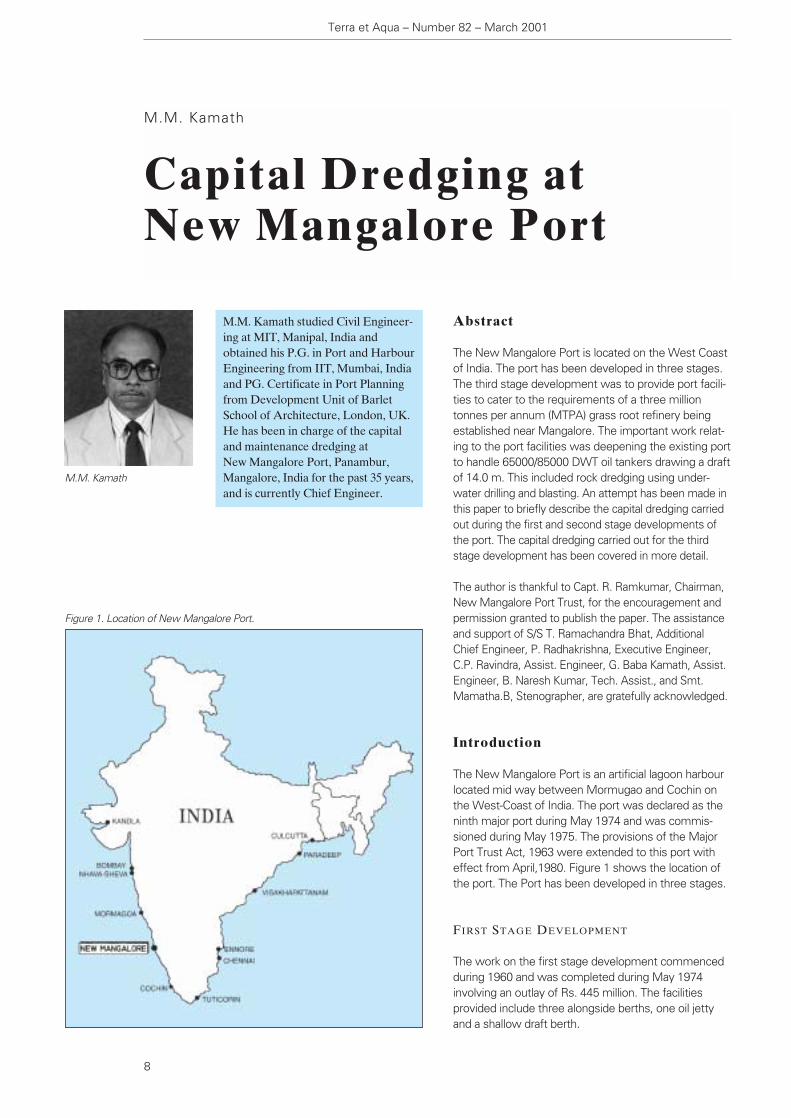
The New Mangalore Port is an artificial lagoon harbourlocated mid way between Mormugao and Cochin onthe West-Coast of India. The port was declared as theninth major port during May 1974 and was commis-sioned during May 1975. The provisions of the MajorPort Trust Act, 1963 were extended to this port witheffect from April,1980. Figure 1 shows the location ofthe port. The Port has been developed in three stages.
FIRST STAGE DEVELOPMENT
The work on the first stage development commencedduring 1960 and was completed during May 1974involving an outlay of Rs. 445 million. The facilitiesprovided include three alongside berths, one oil jettyand a shallow draft berth.
M.M. Kamath
Capital Dredging at New Mangalore Port
Terra et Aqua – Number 82 – March 2001
8
M.M. Kamath studied Civil Engineer-ing at MIT, Manipal, India andobtained his P.G. in Port and HarbourEngineering from IIT, Mumbai, Indiaand PG. Certificate in Port Planningfrom Development Unit of BarletSchool of Architecture, London, UK.He has been in charge of the capitaland maintenance dredging at New Mangalore Port, Panambur,Mangalore, India for the past 35 years,and is currently Chief Engineer.
M.M. Kamath
Figure 1. Location of New Mangalore Port.

9
The first stage development of the port was to cater tothe requirement of 30000 DWT vessels drawing adraught of 9.15 m and the following depths wereprovided in the various zones:
Outer approach channel – 10.7 mCD
Lagoon – 10.1 mCD
Alongside berths – 9.75 mCD
The New Mangalore Port is completely an artificiallagoon harbour. Hence, an approach channel had to bedredged in the sea and a lagoon had to be cut out inthe virgin land. The typical soil profile at the port con-sists of a layer of sand extending to a depth of about –8to –10 mCD followed by a layer of medium to stiff clayfollowed by soft and hard rock.
The average elevation of the lagoon area was of theorder of +5.0 mCD. Hence the area covered by thelagoon was excavated in dry using the earth movingequipments up to a level of about +1.0 mCD (theaverage level of groundwater). The excavation belowthis level was carried out by dredging. The top layer ofsand was used for reclaiming the low-lying areas in andaround the port. The soil below the sand being claywhich was not suitable for reclamation was dumped inthe offshore dumping area located at a distance of 4.5 km southwest from the point of intersection of thecentre line of the outer approach channel with the –15 m contour. The distance of the dumping groundfrom the shoreline was about 9.0 km.
The initial dredging of the port was carried out by a smallcutter suction dredger fabricated in the port. The workcommenced during 1969. The dredger was fabricated on land and slid into a nearby pond created earlier. Once afloat, the dredger was utilised for reclaiming theadjacent low-lying areas within a radius of about 400 m.As this dredger had only limited capacity, the balancedredging was entrusted to the Dredging Corporation ofIndia, Limited (DCI Ltd) during Nov.1970. They deployedtwo cutter suction dredgers. These dredgers had to bebrought inside the lagoon by creating their own floatationby dredging a pilot channel. Once inside the lagoon, thetop mantle of dredged sand was used for reclamation ofthe adjacent low-lying areas.
In view of the large quantity of dredging involved andas suitable dredgers were not available within DCI, thebalance portion of the work was entrusted to a consor-tium of four Dutch dredging companies viz. M/s.Dredg-ing Consortium India B.V. during 1973 after an invitationfor global tenders. The first stage development of theport is shown in Figure 2.
The final quantities dredged during the first stagedevelopment dredging work were as under:
Method of dredging Qty. in million m3.
– Departmental cutter suction 3.267 dredgers in the lagoon.
– Contract dredging– Outer approach channel 2.776– Lagoon 7.343
——————-Total 13.386
The dredging work of first stage developmentcommenced during 1970 and was completed during1974. The total expenditure incurred for the first stagedevelopment of the dredging work, including paymentof customs duty and such, was Rs.149.3 million (1974).
A brief description of the dredging carried out by thedepartmental dredgers and the contract dredging isfurnished in Annexes I and II respectively.
SECOND STAGE DEVELOPMENT — EXPANSION
OF PORT FACILITIES FOR KUDREMUKH
DEVELOPMENT
During the year 1976, the Govt. of India approved thescheme for expansion of the New Mangalore Port tocater to the export of 7.5 MTPA of Kudremukh iron oreconcentrates to Iran. The port was deepened to providefor 60000 DWT vessels drawing a draught of 12.5 m
Figure 2. First Stage Development.
involving an outlay of Rs. 385 million. The followingdepths were provided in the various zones, by takingadvantage of 1.0 m tide:
Outer approach channel – 13.5 mCDLagoon – 13.0 mCDIron ore berth – 13.0 mCD
The total quantity of dredging involved was 9.35 millionm3 as under:
Outer approach channel: 5.29 million m3
Lagoon 4.06 million m3
The dredging work was carried out by the DCI, Ltd.during the period from October 1977 to December 1981.
In addition to the above, certain stray rock patches werealso encountered in the lagoon during the first stagedevelopment at a depth of about – 8.2 mCD. These rockpatches covered an area of about 47,500 m2. These rocks were removed by under water drilling andblasting. For underwater drilling and blasting, a four-legged jack-up platform fitted with four overburdendrilling equipment was used. Two grab dredgers assistedby split barges carried out the dredging of the blastedrock. A total quantity of 31,200 m3 of rock was removed.
The details of the capital dredging and the underwaterblasting carried out during the second stage develop-ment of the port is furnished in Annexes III and IVrespectively.
Construction of additional general cargo berths on thewestern side of eastern dock On completion of Kudremukh Development Scheme,the work on the construction of additional generalcargo berths on the western side of the eastern dockarm was commenced during 1981 and was commis-sioned during 1984. The berth was constructed in dryon land. A quantity of about 0.14 million m3 of soil infront of the berth was later dredged by a cutter suctiondredger and the soil was used for reclamation in theadjacent areas.
The work on the balance portion of the additional generalcargo berth on the western side of the eastern dock armwas commenced during 1987 and completed during1989. This berth was also constructed in dry on land. In connection with this development, a total quantity of0.14 million m3. of soil was dredged by the cutter suctiondredger and the soil was used for reclamation in theadjacent areas. The details of the dredging carried out inconnection with the additional general cargo berths aredetailed in Annex V.
With the completion of this balance portion of the additional general cargo berths on the western side,
10
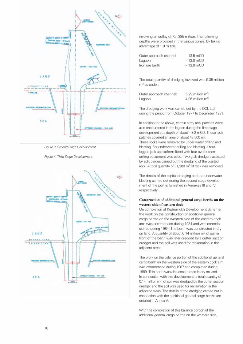
Figure 3. Second Stage Development.
Figure 4. Third Stage Development.
Area Quantity in million m3
Dry excavation in the new dock arm – 0.317
Cutter suction dredging in thenew dock arm and reclamation on the beach – 2.428
Dredging in the lagoon & offshoredumping – 2.950
Dredging in the outer approachchannel and offshore dumping –5.870
——————Total 11.565
In addition, 0.21 million m3 of overburden dredging,including 34,320 m3 of rock had been drilled, blastedand removed in the lagoon.
The contract also included maintenance dredging in theouter approach channel during the intervening mon-soon periods of 1994-95 and 1995-96 involving a quan-tity of 6.83 million m3. This was dredged by a trailersuction hopper dredger and the material was disposedoff in the offshore dumping area.
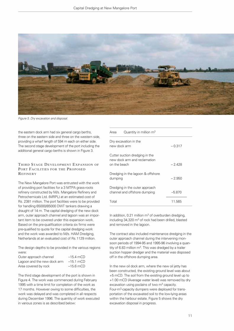
In the new oil dock arm, where the new oil jetty hasbeen constructed, the existing ground level was about+5 mCD. The soil from the existing ground level up to+1.00 mCD (Average water level) was removed by dryexcavation using poclains of two m3 capacity. Four-m3-capacity dumpers were deployed for trans-portation of the excavated soil to the low-lying areaswithin the harbour estate. Figure 5 shows the dryexcavation disposal in progress.
the eastern dock arm had six general cargo berths, three on the eastern side and three on the western side,providing a wharf length of 594 m each on either side.The second stage development of the port including theadditional general cargo berths is shown in Figure 3.
THIRD STAGE DEVELOPMENT EXPANSION OF
PORT FACILITIES FOR THE PROPOSED
REFINERY
The New Mangalore Port was entrusted with the workof providing port facilities for a 3 MTPA grass-rootsrefinery constructed by M/s. Mangalore Refinery andPetrochemicals Ltd. (MRPL) at an estimated cost of Rs. 2381 million. The port facilities were to be providedfor handling 65000/85000 DWT tankers drawing adraught of 14 m. The capital dredging of the new dockarm, outer approach channel and lagoon was an impor-tant item to be covered under this expansion work.Based on the pre-qualification criteria six firms werepre-qualified to quote for the capital dredging work and the work was awarded to M/s. HAM Dredging,Netherlands at an evaluated cost of Rs.1129 million.
The design depths to be provided in the various regionswere:Outer approach channel –15.4 mCD Lagoon and the new dock arm –15.1 mCDArea covered by rock –15.6 mCD
The third stage development of the port is shown inFigure 4. The work was commenced during February1995 with a time limit for completion of the work as 17 months. However owing to some difficulties, thework was delayed and was completed in all respectsduring December 1996. The quantity of work executedin various zones is as described below:
Capital Dredging at New Mangalore Port
11
Figure 5. Dry excavation and disposal.
The general soil profile in the port area was sand up toa depth of about –8 to –10 mCD which was followedby medium and stiff clay, soft rock and hard rock.
Ever since the construction of the breakwaters duringthe first stage development, there has been slighterosion south of the south breakwater over the years.This was mainly a result of the small net southerly drift.In order to arrest this erosion and also to provide for afuture buffer stock, a quantity of about 2.43 million m3
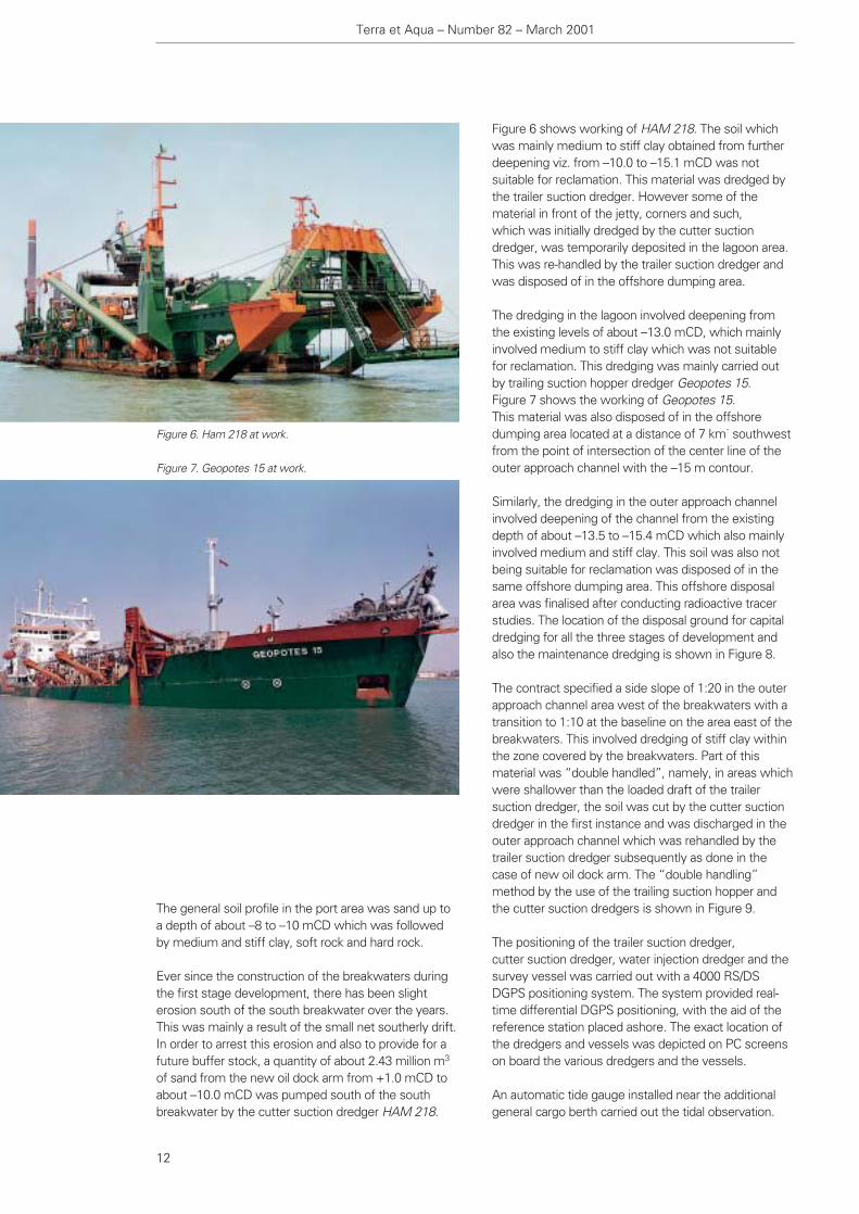
of sand from the new oil dock arm from +1.0 mCD toabout –10.0 mCD was pumped south of the southbreakwater by the cutter suction dredger HAM 218.
Figure 6 shows working of HAM 218. The soil whichwas mainly medium to stiff clay obtained from furtherdeepening viz. from –10.0 to –15.1 mCD was notsuitable for reclamation. This material was dredged bythe trailer suction dredger. However some of thematerial in front of the jetty, corners and such, which was initially dredged by the cutter suctiondredger, was temporarily deposited in the lagoon area. This was re-handled by the trailer suction dredger andwas disposed of in the offshore dumping area.
The dredging in the lagoon involved deepening fromthe existing levels of about –13.0 mCD, which mainlyinvolved medium to stiff clay which was not suitablefor reclamation. This dredging was mainly carried outby trailing suction hopper dredger Geopotes 15. Figure 7 shows the working of Geopotes 15. This material was also disposed of in the offshoredumping area located at a distance of 7 km˙ southwestfrom the point of intersection of the center line of theouter approach channel with the –15 m contour.
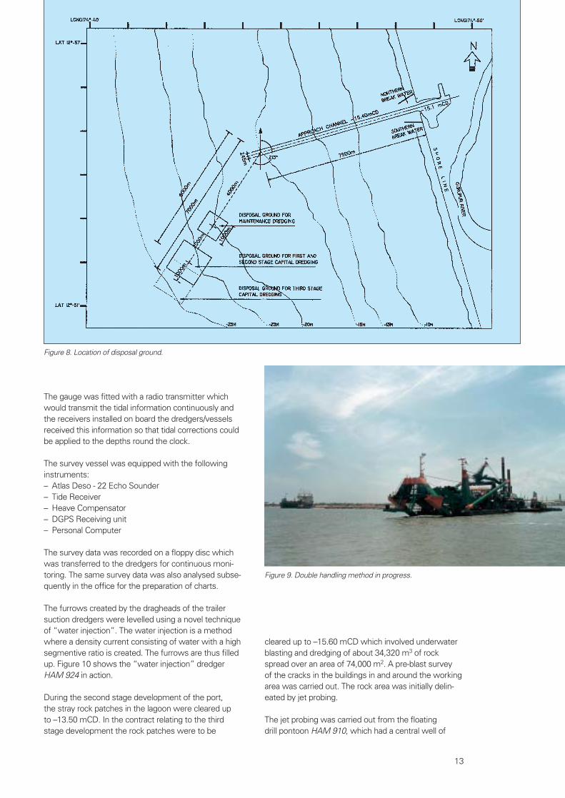
Similarly, the dredging in the outer approach channelinvolved deepening of the channel from the existingdepth of about –13.5 to –15.4 mCD which also mainlyinvolved medium and stiff clay. This soil was also notbeing suitable for reclamation was disposed of in thesame offshore dumping area. This offshore disposalarea was finalised after conducting radioactive tracerstudies. The location of the disposal ground for capitaldredging for all the three stages of development andalso the maintenance dredging is shown in Figure 8.
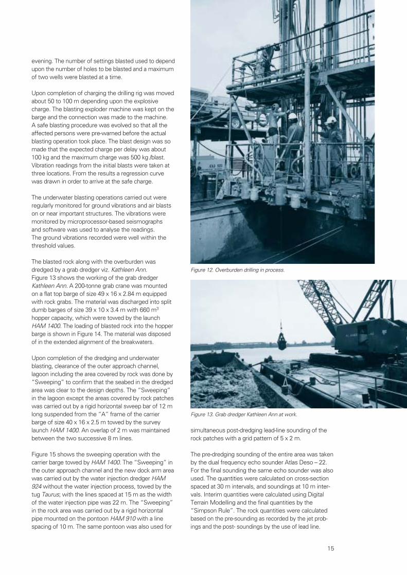
The contract specified a side slope of 1:20 in the outerapproach channel area west of the breakwaters with atransition to 1:10 at the baseline on the area east of thebreakwaters. This involved dredging of stiff clay withinthe zone covered by the breakwaters. Part of thismaterial was “double handled”, namely, in areas whichwere shallower than the loaded draft of the trailersuction dredger, the soil was cut by the cutter suctiondredger in the first instance and was discharged in theouter approach channel which was rehandled by thetrailer suction dredger subsequently as done in thecase of new oil dock arm. The “double handling”method by the use of the trailing suction hopper andthe cutter suction dredgers is shown in Figure 9.
The positioning of the trailer suction dredger, cutter suction dredger, water injection dredger and thesurvey vessel was carried out with a 4000 RS/DSDGPS positioning system. The system provided real-time differential DGPS positioning, with the aid of thereference station placed ashore. The exact location ofthe dredgers and vessels was depicted on PC screenson board the various dredgers and the vessels.
An automatic tide gauge installed near the additionalgeneral cargo berth carried out the tidal observation.
Terra et Aqua – Number 82 – March 2001
12
Figure 6. Ham 218 at work.
Figure 7. Geopotes 15 at work.
cleared up to –15.60 mCD which involved underwaterblasting and dredging of about 34,320 m3 of rockspread over an area of 74,000 m2. A pre-blast survey of the cracks in the buildings in and around the workingarea was carried out. The rock area was initially delin-eated by jet probing.
The jet probing was carried out from the floating drill pontoon HAM 910, which had a central well of
The gauge was fitted with a radio transmitter whichwould transmit the tidal information continuously andthe receivers installed on board the dredgers/vesselsreceived this information so that tidal corrections couldbe applied to the depths round the clock.
The survey vessel was equipped with the followinginstruments:– Atlas Deso - 22 Echo Sounder – Tide Receiver – Heave Compensator – DGPS Receiving unit – Personal Computer
The survey data was recorded on a floppy disc whichwas transferred to the dredgers for continuous moni-toring. The same survey data was also analysed subse-quently in the office for the preparation of charts.
The furrows created by the dragheads of the trailersuction dredgers were levelled using a novel techniqueof “water injection”. The water injection is a methodwhere a density current consisting of water with a highsegmentive ratio is created. The furrows are thus filledup. Figure 10 shows the “water injection” dredgerHAM 924 in action.
During the second stage development of the port, the stray rock patches in the lagoon were cleared up to –13.50 mCD. In the contract relating to the thirdstage development the rock patches were to be
13
Figure 8. Location of disposal ground.
Figure 9. Double handling method in progress.

9.40 x 5.30 m equipped with a gantry. Figure 11 showsthe drilling platform HAM 910. On the gantry four drilltowers of 12 m length equipped with Over Burdendrilling system (OD) were installed. The pontoon washeld in position by six anchors. The anchor wincheswere controlled from a centralised control panel. Based on the jet probings carried out initially, the set-tings of the drilling platform in the area covered by rockwere pre-plotted. As the accuracy required for thelocation of the platform was of a high order, a systemhaving an accuracy of better than the DGPS viz.“Axyle” was deployed.
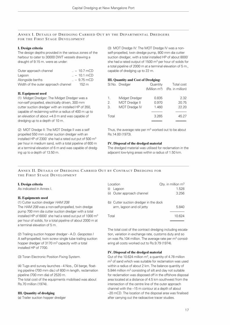
With a central well of 9.40 x 5.30 m and four drill towers, holes with a grid spacing of 1.77 x 1.88 mwere adopted. This resulted in 24 holes in each setting.A 70-mm drill hole was drilled using the OD equipmentto the required depth. Figure 12 shows the drilling inprogress.
The holes were drilled 2 m deeper than the designdepth [called as undercut] to provide for proper break-age of the rock. On reaching the required depth, theexplosives were loaded into the drilled holes. Theexplosive used was slurry explosive “KELVEX 800”/50mm dia x 400 mm cartridge with a plastic casing whichhad screwed ends on either side so that they could beeasily coupled. The full depth of the hole was packedwith explosives.
Two VA-OD short delay millisecond electric delaydetonators, which were pre-checked, were used in eachhole as a matter of precaution. On completion of thecharging of all the holes, the detonator leads from indi-vidual holes were connected in parallel/series connec-tion, depending upon the number of holes in the circuit.The circuit was also checked for continuity and resis-tance. The blasting was done normally during daylighthours only, once in the morning and the second in the
Figure 10. Water injection dredger Ham 924 at work.
Figure 11. Drilling Platform Ham 910.
simultaneous post-dredging lead-line sounding of therock patches with a grid pattern of 5 x 2 m.
The pre-dredging sounding of the entire area was takenby the dual frequency echo sounder Atlas Deso – 22.For the final sounding the same echo sounder was alsoused. The quantities were calculated on cross-sectionspaced at 30 m intervals, and soundings at 10 m inter-vals. Interim quantities were calculated using DigitalTerrain Modelling and the final quantities by the “Simpson Rule”. The rock quantities were calculatedbased on the pre-sounding as recorded by the jet prob-ings and the post- soundings by the use of lead line.
evening. The number of settings blasted used to dependupon the number of holes to be blasted and a maximumof two wells were blasted at a time.
Upon completion of charging the drilling rig was movedabout 50 to 100 m depending upon the explosivecharge. The blasting exploder machine was kept on thebarge and the connection was made to the machine. A safe blasting procedure was evolved so that all theaffected persons were pre-warned before the actualblasting operation took place. The blast design was somade that the expected charge per delay was about100 kg and the maximum charge was 500 kg /blast.Vibration readings from the initial blasts were taken atthree locations. From the results a regression curvewas drawn in order to arrive at the safe charge.
The underwater blasting operations carried out wereregularly monitored for ground vibrations and air blastson or near important structures. The vibrations weremonitored by microprocessor-based seismographs and software was used to analyse the readings. The ground vibrations recorded were well within thethreshold values.
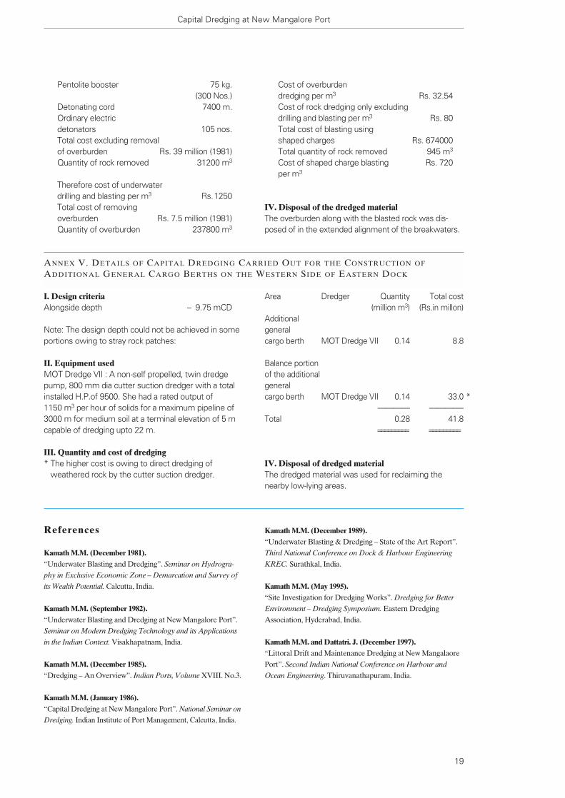
The blasted rock along with the overburden wasdredged by a grab dredger viz. Kathleen Ann. Figure 13 shows the working of the grab dredgerKathleen Ann. A 200-tonne grab crane was mountedon a flat top barge of size 49 x 16 x 2.84 m equippedwith rock grabs. The material was discharged into splitdumb barges of size 39 x 10 x 3.4 m with 660 m3
hopper capacity, which were towed by the launchHAM 1400. The loading of blasted rock into the hopperbarge is shown in Figure 14. The material was disposedof in the extended alignment of the breakwaters.
Upon completion of the dredging and underwaterblasting, clearance of the outer approach channel,lagoon including the area covered by rock was done by“Sweeping” to confirm that the seabed in the dredgedarea was clear to the design depths. The “Sweeping”in the lagoon except the areas covered by rock patcheswas carried out by a rigid horizontal sweep bar of 12 mlong suspended from the “A” frame of the carrierbarge of size 40 x 16 x 2.5 m towed by the surveylaunch HAM 1400. An overlap of 2 m was maintainedbetween the two successive 8 m lines.
Figure 15 shows the sweeping operation with thecarrier barge towed by HAM 1400. The “Sweeping” inthe outer approach channel and the new dock arm areawas carried out by the water injection dredger HAM924 without the water injection process, towed by thetug Taurus; with the lines spaced at 15 m as the widthof the water injection pipe was 22 m. The “Sweeping”in the rock area was carried out by a rigid horizontalpipe mounted on the pontoon HAM 910 with a linespacing of 10 m. The same pontoon was also used for
15
Figure 12. Overburden drilling in process.
Figure 13. Grab dredger Kathleen Ann at work.

Conclusion
The Detailed Project Report for providing port facilitiesfor the refinery for the third stage development wasprepared by M/s. Consulting Engineering Services(India) Pvt. Ltd., (CES) , New Delhi, during 1985. The detailed engineering for the entire port facilitieswas also done by M/s. CES during 1993. The hydraulicmodel studies and other studies was carried out by the
Central Water and Power Research Station, Pune. The radioactive traces studies were carried out byBhaba Atomic Research Centre, Mumbai.
The work of dredging for the third stage developmentwas awarded to M/s. HAM Dredging after competitivebidding during November 1995 and the work wascompleted during December 1996.
Terra et Aqua – Number 82 – March 2001
16
Figure 14. Loading of blasted rock into hopper barge.
Figure 15. Sweeping operation with carrier barge towed by HAM 1400.
(3) MOT Dredge IV: The MOT Dredge IV was a non-self-propelled, twin dredge pump, 800 mm dia cuttersuction dredger, with a total installed HP of about 8000˙she had a rated output of 1500 m3 per hour of solids fora total pipeline of 2000 m at a terminal elevation of 5 m.,capable of dredging up to 22 m.
III. Quantity and Cost of Dredging:Sl.No. Dredger Quantity Total cost
(Million m3) (Rs. in million)
1. Midget Dredger 0.835 2.322. MOT Dredge II 0.970 20.753. MOT Dredge IV 1.460 22.20
———- ———-Total 3.265 45.27
======= =======
Thus, the average rate per m3 worked out to be aboutRs.14.00 (1973).
IV. Disposal of the dredged materialThe dredged material was utilised for reclamation in theadjacent low-lying areas within a radius of 1.50 km.
I. Design criteriaThe design depths provided in the various zones of theharbour to cater to 30000 DWT vessels drawing adraught of 9.15 m. were as under:
Outer approach channel .. – 10.7 mCDLagoon .. – 10.1 mCDAlongside berths .. – 9.75 mCDWidth of the outer approach channel 152 m
II. Equipment used(1) Midget Dredger: The Midget Dredger was a non-self propelled, electrically driven, 300 mm cutter suction dredger with an installed HP of 350, capable of reclaiming within a radius of 400 m up to an elevation of about +4.0 m and was capable of dredging up to a depth of 10 m.
(2) MOT Dredge II: The MOT Dredge II was a selfpropelled 550 mm cutter suction dredger with aninstalled HP of 2300˙ she had a rated out put of 500 m3
per hour in medium sand, with a total pipeline of 600 mat a terminal elevation of 6 m and was capable of dredg-ing up to a depth of 13.50 m.
Capital Dredging at New Mangalore Port
17
ANNEX I. DETAILS OF DREDGING CARRIED OUT BY THE DEPARTMENTAL DREDGERS
FOR THE FIRST STAGE DEVELOPMENT
ANNEX II. DETAILS OF DREDGING CARRIED OUT BY CONTRACT DREDGING FOR
THE FIRST STAGE DEVELOPMENT
I. Design criteriaAs indicated in Annex I.
II. Equipments used(1) Cutter suction dredger HAM 208The HAM 208 was a non-self-propelled, twin dredgepump 700 mm dia cutter suction dredger with a totalinstalled HP of 6000˙ she had a rated out put of 1000 m3
per hour of solids, for a total pipeline of about 2000 m ata terminal elevation of 5 m.
(2) Trailing suction hopper dredger - A.D. Geopotes IA self-propelled, twin screw single tube trailing suctionhopper dredger of 3170 m3 capacity with a totalinstalled HP of 7700.
(3) Toran Electronic Position Fixing System.
(4) Tugs and survey launches - 4 Nos., Oil barge, float-ing pipeline (700 mm dia.) of 600 m length, reclamationpipeline (700 mm dia) of 2520 m. The total cost of the equipments mobilised was aboutRs.70 million (1974).
III. Quantity of dredging(a) Trailer suction hopper dredger
Location Qty. in million m3
(i) Lagoon 1.528 (ii) Outer approach channel 3.256
(b) Cutter suction dredger in the dock arm, lagoon and oil jetty 5.840
———-—Total 10.624
=========
The total cost of the contract dredging including escala-tion, variation in exchange rate, customs duty and soon was Rs.104 million. The average rate per m3 consid-ering all costs worked out to Rs.9.79 (1974).
IV. Disposal of the dredged materialOut of the 10.624 million m3, a quantity of 4.78 millionm3 of sand which was suitable for reclamation was usedwithin a radius of about 2 km. The balance quantity of5.844 million m3 consisting of silt and clay not suitablefor reclamation was disposed off in the offshore disposalarea located at a distance of 4.5 km southwest from theintersection of the centre line of the outer approachchannel with the –15 m contour at a depth of about –20 mCD. The location of the disposal area was finalisedafter carrying out the radioactive tracer studies.

I. Design criteriaThe design depths provided in various zones for hand-ling 60000 DWT ore carriers drawing a draft of 12.5 mtaking advantage of 1 m tide were as under:
Outer approach channel – 13.5 mCDLagoon – 13.0 mCDIron ore berth – 13.0 mCDWidth of the outer approach channel 245 m
II. Equipments used(1) MOT Dredge VIII: 6500 m3 twin screw, twin tubetrailer suction hopper dredger with a total installed HPof about 15000 capable of dredging up to 25 m. (2) MOT Dredge III: 3400 m3 twin screw, twin tubetrailer suction hopper dredger with a total installed HPof about 10000 capable of dredging up to 22 m.(3) MOT Dredge VI: 3700 m3 twin screw, twin tubetrailer suction hopper dredger with a total installed HPof about 10,000 capable of dredging up to 22 m.(4) MOT Dredge VII: 800 mm dia non-self-propelledcutter suction dredger, twin dredge pump with a totalinstalled HP of 8500 capable of dredging up to 22 m.She had a rated output of 1150 m3/hour of solids for atotal pipeline of 3000 m at a terminal elevation of 5 m.
III. Quantity of dredging carried out
Location Qty. in million m3
Outer approach channel 5.294 Lagoon 4.067
—————Total 9.361
==========
NOTE: Out of the above a quantity of 2.50 million m3
which was dredged by the cutter suction dredger, was re-handled by the trailer suction dredgers by doublehandling, on the slopes of the outer approach channeland the lagoon.
The total cost of capital dredging including escalation,customs duty and such was Rs.238.5 million. The average rate per m3 considering all costs workedout to about Rs.25.50 (1981).
IV. Disposal of the dredged materialAs the work involved deepening of the existing harbourand the material involved was mostly clay, the dredgedmaterial was disposed of in the offshore dumping areaas in the first stage development.
Terra et Aqua – Number 82 – March 2001
18
ANNEX III. DETAILS OF CAPITAL DREDGING CARRIED OUT FOR THE SECOND STAGE
DEVELOPMENT
ANNEX IV. DETAILS OF UNDERWATER BLASTING WORK CARRIED OUT FOR THE SECOND
STAGE DEVELOPMENT
I. Design criteriaThe design depths provided in the lagoon in the areascovered by rock was 0.5 m more than the normaldepths viz. –13.5 mCD, to provide for additional keelclearance owing to the hard rock bottom.
II. Equipments used(1) Jack-Up Type Drill Rig (Model MK-II):
Overall length 27.58 mBreadth 18.18 mDepth 2.01 mDraught 0.70 m
Fitted with four jack-up spuds and 4 nos. drill towersmounted on a central well capable of drilling up to 20 massisted by 4 nos. of air compressors.
(2) Pontoon mounted crawler crane:150 tonnes capacity, mounted on a pontoon of 45 x 15 x 3.6 m.
(3) Pontoon mounted crawler crane:100 tonne capacity, mounted on a pontoon of 40 x 16 x 2.5 m.
(4) Self-propelled 750 m3 “hydroklapp barge”
(5) Non-self-propelled split barge of 150 m3 capacity.
(6) Tug MK-II Type - 1 No.
(7) 100 Tonne deck loading barge - 1 No.
(8) Sweeping pontoon - 1 No.
III. Quantity of dredging carried outA. Drilling and Blasting:
Rock area 47500 sqmQuantity of over-burden 237800 m3
Quantity of rock 31200 m3
Total quantity of explosives used (Dynamax A 40 mm size) 81.5 tonnesMillisecond electric delay detonators VA-OD type 12520 nos
B. Shaped charge blasting : 10 litre containers 750 nos.Explosives used 9100 kg.(Supergel & Kelvex 800)
Cost of overburdendredging per m3 Rs. 32.54Cost of rock dredging only excluding drilling and blasting per m3 Rs. 80 Total cost of blasting using shaped charges Rs. 674000Total quantity of rock removed 945 m3
Cost of shaped charge blasting Rs. 720 per m3
IV. Disposal of the dredged materialThe overburden along with the blasted rock was dis-posed of in the extended alignment of the breakwaters.
Pentolite booster 75 kg.(300 Nos.)
Detonating cord 7400 m.Ordinary electric detonators 105 nos.Total cost excluding removal of overburden Rs. 39 million (1981)Quantity of rock removed 31200 m3
Therefore cost of underwater drilling and blasting per m3 Rs.1250Total cost of removing overburden Rs. 7.5 million (1981)Quantity of overburden 237800 m3
Capital Dredging at New Mangalore Port
ANNEX V. DETAILS OF CAPITAL DREDGING CARRIED OUT FOR THE CONSTRUCTION OF
ADDITIONAL GENERAL CARGO BERTHS ON THE WESTERN SIDE OF EASTERN DOCK
19
I. Design criteriaAlongside depth – 9.75 mCD
Note: The design depth could not be achieved in someportions owing to stray rock patches:
II. Equipment usedMOT Dredge VII : A non-self propelled, twin dredgepump, 800 mm dia cutter suction dredger with a totalinstalled H.P.of 9500. She had a rated output of 1150 m3 per hour of solids for a maximum pipeline of3000 m for medium soil at a terminal elevation of 5 mcapable of dredging upto 22 m.
III. Quantity and cost of dredging* The higher cost is owing to direct dredging of
weathered rock by the cutter suction dredger.
Area Dredger Quantity Total cost(million m3) (Rs.in millon)
Additional general cargo berth MOT Dredge VII 0.14 8.8
Balance portion of the additionalgeneral cargo berth MOT Dredge VII 0.14 33.0
———— ————-Total 0.28 41.8
========= =========
IV. Disposal of dredged materialThe dredged material was used for reclaiming thenearby low-lying areas.
References
Kamath M.M. (December 1981).“Underwater Blasting and Dredging”. Seminar on Hydrogra-
phy in Exclusive Economic Zone – Demarcation and Survey of
its Wealth Potential. Calcutta, India.
Kamath M.M. (September 1982).“Underwater Blasting and Dredging at New Mangalore Port”.
Seminar on Modern Dredging Technology and its Applications
in the Indian Context. Visakhapatnam, India.
Kamath M.M. (December 1985).“Dredging – An Overview”. Indian Ports, Volume XVIII. No.3.
Kamath M.M. (January 1986).“Capital Dredging at New Mangalore Port”. National Seminar on
Dredging. Indian Institute of Port Management, Calcutta, India.
Kamath M.M. (December 1989).“Underwater Blasting & Dredging – State of the Art Report”.
Third National Conference on Dock & Harbour Engineering
KREC. Surathkal, India.
Kamath M.M. (May 1995).“Site Investigation for Dredging Works”. Dredging for Better
Environment – Dredging Symposium. Eastern Dredging
Association, Hyderabad, India.
Kamath M.M. and Dattatri. J. (December 1997).“Littoral Drift and Maintenance Dredging at New Mangalaore
Port”. Second Indian National Conference on Harbour and
Ocean Engineering. Thiruvanathapuram, India.
*

Terra et Aqua – Number 82 – March 2001
20
Abstract
In 1998, nine international oil companies formed anoperating company in Kazakhstan, OKIOC (OffshoreKazakhstan International Operating Company), to carryout a six-year oil and gas exploration programme in theKazakh sector of the Northeast Caspian Sea. At thedrilling areas, OKIOC contracted with Boskalis Interna-tional b.v. to build underwater berms to withstand theforces of waves and moving ice. Although the size ofthese berms are not especially large, the real challengesbeing faced during this project are the sensitive environ-ment, the complex local regulations, the poor quality ofthe rock, the harsh climate and the overall logistics andsafety, as well as the deep cultural differences.
Introduction
In 1998, nine international oil companies formed anoperating company in Kazakhstan, OKIOC (OffshoreKazakhstan International Operating Company), to carryout a six-year oil and gas exploration programme in the Kazakh sector of the Northeast Caspian Sea. The offshore exploration programme covers an area of 6,000 km2 (see Figure 1).
The seismic programme started approximately sixyears ago and in August 1999 exploration drilling beganfor the first time in the Kazakhstan sector of theCaspian Sea. The result of this exploration hole becameavailable in the summer of 2000, and forms the basisfor an anticipated increase in activities in the north-eastern sector of the Caspian Sea.
Five exploration holes have been nominated: – Kashagan East, – Kashagan West, – Kalamkas, – Aktote and – Kairan.
Carol Granneman and Arjan Goris
Kazakhstan, OffshoreExploration in the Caspian Sea
Carol Granneman received an MSc inCivil Engineering from TechnicalUniversity Delft (The Netherlands)in 1984 and an MBA from HenleyManagement College (UK) in 1998. In 1990 he joined Boskalis, starting inthe IT department and later working inthe Marketing Department. Work inKazakhstan comprised managingQA/HSE, Production/Planning for theproject and Superintendent. He ispresently working as a ProjectManager for Boskalis in Norway.
Carol Granneman
Arjan Goris graduated with a MSc inMining Engineering from Technical University Delft (The Netherlands).For the past 14 years he has worked forseveral mining companies in under-ground and open cast mines in SouthAfrica and South America, the last 5 years of that as Head MiningOperations of a bauxite mine inSurinam. He joined BoskalisWestminister in 1998 and was sent toKazakhstan. Since mid-1999 he hasbeen Boskalis’ Project Manager inKazakstan, responsible for alloperations and contacts with the clientOKIOC.
Arjan Goris

A drilling barge has been modified to allow drilling inshallow waters and for drilling under the extremewinter conditions existing in this part of the CaspianSea. The barge was widened, equipped with icedeflector shields and with all necessary equipment tocontinue its drilling operation during the winter. It isplaced on top of a berm, with the purpose of this bermbeing to provide a footing and stability at a pre-determined depth (depending on prevailing waterlevels in the Caspian Sea).
Boskalis International b.v. has been involved in theconstruction of these berms during the constructionyears 1998-2001.
Kashagan East was the first exploration location, at which the drilling rig began the search for oil and gas. The drilling depth of this well was expected to be 4,500 m, but was later extended to beyond 6,000 metres.
THE LOCAL CIRCUMSTANCES
OKIOC has a Production Sharing Agreement with thegovernment of Kazakhstan. One of the terms of thisagreement deals with the local content of personneland equipment to be used under the agreement. Implicitly this means that a large part of the operationhas to be executed with local equipment and personnel.
After more than two years of experience in Kazakhstan,a better understanding and relationship could havedeveloped between the Contractors and the local author-ities. Unfortunately, this situation has not materialised,and many problems that the Contractors face are relatedto local authorities pursuing their own (hidden) agendasand requiring an ever-bigger input in the operations. This situation is true for all the companies involved in theproject, with the bigger and more renowned companiesfacing the same or even bigger problems.
The pressure is for a large part related to the very highunemployment in (West) Kazakhstan. Towns, districtsand regions are fending for themselves and competingwith each other for econonic development. Each hasits own targets and problems, and does not favour the employment of personnel from other regions ofKazakhstan (not even from a nearby city).
To illustrate the local differences, not so long ago thelocal mayor of Fort Shevchenko (Akim) orderedBoskalis to dismiss an employee living in Aktau, on the(illegal) grounds that only people from his district wereallowed to work within his district. Having adhered tothat request/demand and having dismissed the saidemployee, a court order from the city of Aktau arrivedthat this was an illegal act, and a penalty had to be paidby Boskalis in order to alleviate any further legal
Kazakhstan, Offshore Exploration in the Caspian Sea
21
Figure 1. Location map of the area and of the two explorationholes presently drilled.
actions. The Akim in Fort Shevchenko did not take anyresponsibility for this action, and pretended to knownothing about the instruction.
With a constant request for your passport, travelling between the neighbouring regions of Mangistau and Atyrau give the illusion that you aretravelling to another country. In addition, the old Sovietsystem of foreigner registration in any new district stillapplies, with each district (town) using its own rulesand habits, which makes travelling within Kazakhstan avery cumbersome affair.
The application for any permit or permission to workinvolves often more than one Ministerial Department.Ministries of Ecological Affairs, Transport, Fishery andForeign Affairs are scrambling to have the final say inany application, which makes the process a long andtedious affair. To omit one Department in the applica-tion process could result in the total rejection of theapplication and the formulation of an “Act”. The Actwill state all violations of the Kazakhstan Laws and isthe basis for further penalties and fines. The first timesuch an Act is made, it becomes clear that this systemis a remnant of the Soviet system in which responsibili-ties, accountabilities and further actions are pushed asfar as possible away from the investigating party.
THE BERMS
The term berm applies to an artificially constructedunderwater island, which consists of rock material indifferent gradations, and which is designed to with-stand wave actions and ice forces. Owing to the size
of the barge and the requirement to drill in an exactvertical angle, the top of the berm needed finishingwithin very narrow tolerances.
The first two berms (Kashagan East and Kashagan West)were part of the contract between OKIOC and BoskalisInternational b.v. The berm at Kashagan East was finis-hed in the autumn of 1998 and the second berm inKashagan West was completed in the summer of 1999,well ahead of the arrival of the drilling rig. Slightly differentdesigns were used for these berms, but both designsincluded the use of “ice-breaker piles” to protect theberm and the drill rig against the substantial forces ofmoving ice during the winter and spring.
Although the volume of these berms (11,000 t and44,000 t) is small in comparison to “standard” rockprojects, other elements make this project unusuallycomplex. To mention a few: the sensitive environment,the complex local regulations, the poor quality of therock, the harsh climate and the overall logistics. All together they formed an exceptional challenge tocomplete the works within the tight boundaries oftime, design and safety requirements.
THE ENVIRONMENT
The Northeast Caspian Sea is a State Nature PreserveZone because of the unique combination of shallowwaters (the water depth in the entire North Caspian Seadoes not exceed 10 m), marine organisms, a nestingand feeding place for birds, and the presence of indige-nous vegetation. The coastal wetlands provide thehabitat and breeding grounds for many species.
The region forms an internationally important area forbirds, since it is on the migratory route of many species.
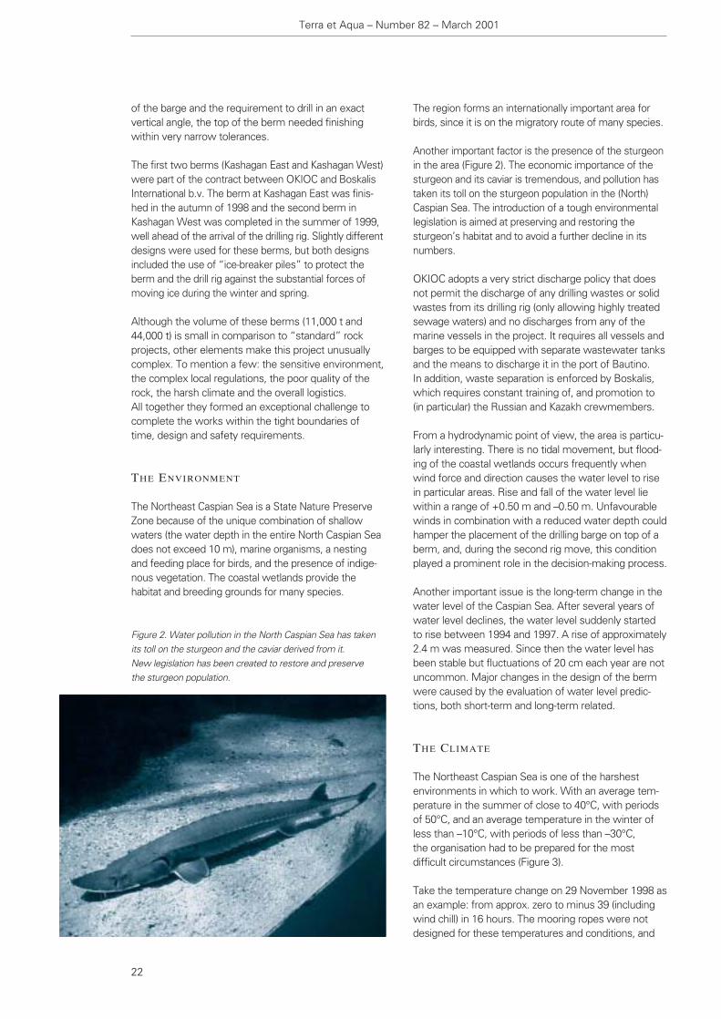
Another important factor is the presence of the sturgeonin the area (Figure 2). The economic importance of thesturgeon and its caviar is tremendous, and pollution hastaken its toll on the sturgeon population in the (North)Caspian Sea. The introduction of a tough environmentallegislation is aimed at preserving and restoring thesturgeon’s habitat and to avoid a further decline in itsnumbers.
OKIOC adopts a very strict discharge policy that doesnot permit the discharge of any drilling wastes or solidwastes from its drilling rig (only allowing highly treatedsewage waters) and no discharges from any of themarine vessels in the project. It requires all vessels andbarges to be equipped with separate wastewater tanksand the means to discharge it in the port of Bautino. In addition, waste separation is enforced by Boskalis,which requires constant training of, and promotion to(in particular) the Russian and Kazakh crewmembers.
From a hydrodynamic point of view, the area is particu-larly interesting. There is no tidal movement, but flood-ing of the coastal wetlands occurs frequently whenwind force and direction causes the water level to risein particular areas. Rise and fall of the water level liewithin a range of +0.50 m and –0.50 m. Unfavourablewinds in combination with a reduced water depth couldhamper the placement of the drilling barge on top of aberm, and, during the second rig move, this conditionplayed a prominent role in the decision-making process.
Another important issue is the long-term change in thewater level of the Caspian Sea. After several years ofwater level declines, the water level suddenly startedto rise between 1994 and 1997. A rise of approximately2.4 m was measured. Since then the water level hasbeen stable but fluctuations of 20 cm each year are notuncommon. Major changes in the design of the bermwere caused by the evaluation of water level predic-tions, both short-term and long-term related.
THE CLIMATE
The Northeast Caspian Sea is one of the harshestenvironments in which to work. With an average tem-perature in the summer of close to 40°C, with periodsof 50°C, and an average temperature in the winter ofless than –10°C, with periods of less than –30°C, the organisation had to be prepared for the most difficult circumstances (Figure 3).
Take the temperature change on 29 November 1998 asan example: from approx. zero to minus 39 (includingwind chill) in 16 hours. The mooring ropes were notdesigned for these temperatures and conditions, and
Terra et Aqua – Number 82 – March 2001
22
Figure 2. Water pollution in the North Caspian Sea has takenits toll on the sturgeon and the caviar derived from it. New legislation has been created to restore and preserve the sturgeon population.

cling drilling mud in Bautino, and constructed the civilworks from the same (rock) material.
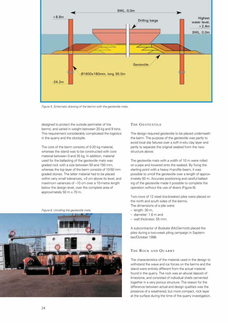
After several changes in the design, it was finally decid-ed that the top of the first berm would be at a level of–3.0 m under mean sea level, whereas the secondberm was finally completed at a level of – 3.2 m undermean sea level (Figure 5).
There were several rock gradations engineered for thedifferent berms and an artificial island: three outsidelayers of armour rock each with a different size were
many snapped owing to the accumulation of ice duringthis cold spell. With waves washing over the aft deckof the Multicat, an ice layer of 10 cm thick was formedwithin hours.
A similar situation occurred during the last onset ofwinter, when the Northeast Caspian Sea (an area notless than 30 by 50 km) was frozen solid (4-5 cm thick-ness) within 24 hours. Imagine a normal flowing riverbeing frozen over within a 24-hour period, with manyfishermen on top of the ice cap fishing through a man-made hole in the ice only half a day later.
The abrupt weather changes are caused by strongwinds, shifting to easterly directions, which bring theSiberian cold over the plains of Kazakhstan without anyobstruction to decrease wind speeds. As a rule, the Northeast Caspian Sea is covered with ice during thewinter, stretching as far as Bautino in severe winters.
Summer temperatures are high, and with the absence ofprecipitation change the landscape into a steppe withvery limited vegetation (approx. 20 cm high, sparselydistributed). Moderate winds create enormous dustclouds, which enter into any nook and crevice onshore.Offshore, this same wind provides some relief duringthese high temperatures and is welcomed by many.
THE DESIGN
The original design of the berm at Kashagan East wasbased on assumptions of certain water levels in theNorth Caspian Sea and estimates of draught and size of the drilling rig. An extensive campaign in 1998 tomeasure the water levels at the drilling locations gavemore information about the water level in the CaspianSea and the short-term variations. At the same time,the drilling rig was assembled in Houston, Texas, USA,and it was not clear what the draught of the bargewould be, especially since further modifications wereplanned in Astrakhan, Russia.
No material in the direct vicinity of the berms wassuitable for the construction, and the dredging optioncould therefore be excluded during this design phase.With extensive marshlands on the Northeast coast, the closest location where (construction) rock wasavailable and could be loaded onto barges was in Bautino, a seaside village at a distance of approximately180 nautical miles from the first berms. The Bautinovillage is part of a cluster of three villages together withAtash and Fort Shevchenko, and is located at a dis-tance of about 150 km from the nearest city of Aktau (Figure 4).
This location was finally chosen as the base fromwhere Boskalis would manage its operations. OKIOC also located its supply base and base for recy-
Kazakhstan, Offshore Exploration in the Caspian Sea
23
Figure 3. The temperatures in the North Caspian Sea area aresome of the harshest and most extreme in the world.
Figure 4. The port of Bautino, a seaside village at a distance ofapproximately 180 nautical miles from the first berms, was theclosest location where (construction) rock was available andcould be loaded onto barges.
designed to protect the outside perimeter of theberms, and varied in weight between 20 kg and 9 tons.This requirement considerably complicated the logisticsin the quarry and the stockpile.
The core of the berm consists of 0-20 kg material,whereas the island was to be constructed with corematerial between 0 and 35 kg. In addition, materialused for the ballasting of the geotextile mats wasgraded rock with a size between 50 and 150 mm,whereas the top layer of the berm consists of 10-50 mmgraded stones. The latter material had to be placedwithin very small tolerances, +0 cm above its level, andmaximum variances of –10 cm over a 10-metre lengthbelow the design level, over the complete area ofapproximately 50 m x 70 m.
THE GEOTEXTILE
The design required geotextile to be placed underneaththe berm. The purpose of the geotextile was partly toavoid local slip failures over a soft in-situ clay layer andpartly to separate the original seabed from the newstructure above.
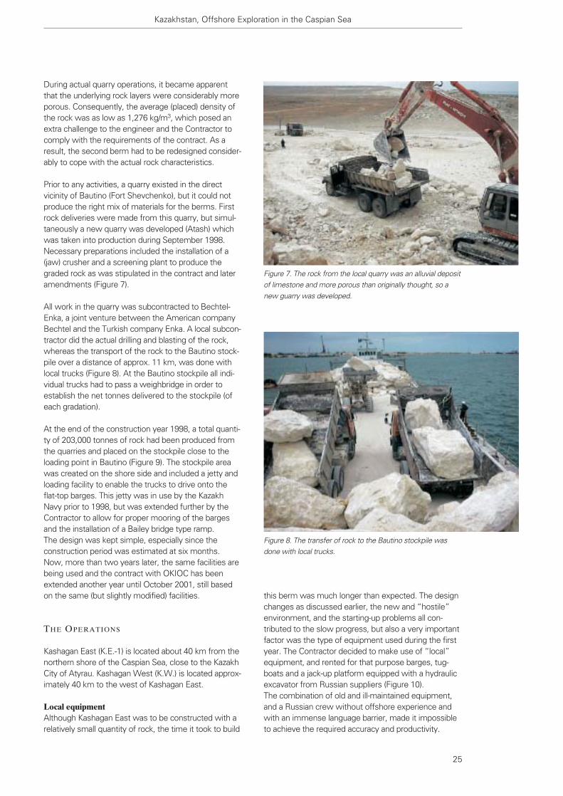
The geotextile mats with a width of 10 m were rolledon a pipe and lowered onto the seabed. By fixing thestarting point with a heavy H-profile beam, it waspossible to unroll the geotextile over a length of approx-imately 50 m. Accurate positioning and careful ballast-ing of the geotextile made it possible to complete theoperation without the use of divers (Figure 6).
Two rows of 12 steel (ice-breaker) piles were placed onthe north and south sides of the berms. The dimensions of a pile were:– length: 30 m, – diameter: 1.6 m and – wall thickness: 55 mm.
A subcontractor of Boskalis (McDermott) placed thepiles during a two-week piling campaign in Septem-ber/October 1998.
THE ROCK AND QUARRY
The characteristics of the material used in the design towithstand the wave and ice forces on the berms and theisland were entirely different from the actual materialfound in the quarry. The rock was an alluvial deposit oflimestone, and consisted of individual shells cementedtogether in a very porous structure. The reason for thedifference between actual and design qualities was thepresence of a weathered, but more compact, rock layerat the surface during the time of the quarry investigation.
24
Figure 5. Schematic drawing of the berms with the geotextile mats.
Figure 6. Unrolling the geotextile mats.
this berm was much longer than expected. The designchanges as discussed earlier, the new and “hostile”environment, and the starting-up problems all con-tributed to the slow progress, but also a very importantfactor was the type of equipment used during the firstyear. The Contractor decided to make use of “local”equipment, and rented for that purpose barges, tug-boats and a jack-up platform equipped with a hydraulicexcavator from Russian suppliers (Figure 10). The combination of old and ill-maintained equipment,and a Russian crew without offshore experience andwith an immense language barrier, made it impossibleto achieve the required accuracy and productivity.
During actual quarry operations, it became apparentthat the underlying rock layers were considerably moreporous. Consequently, the average (placed) density ofthe rock was as low as 1,276 kg/m3, which posed anextra challenge to the engineer and the Contractor tocomply with the requirements of the contract. As aresult, the second berm had to be redesigned consider-ably to cope with the actual rock characteristics.
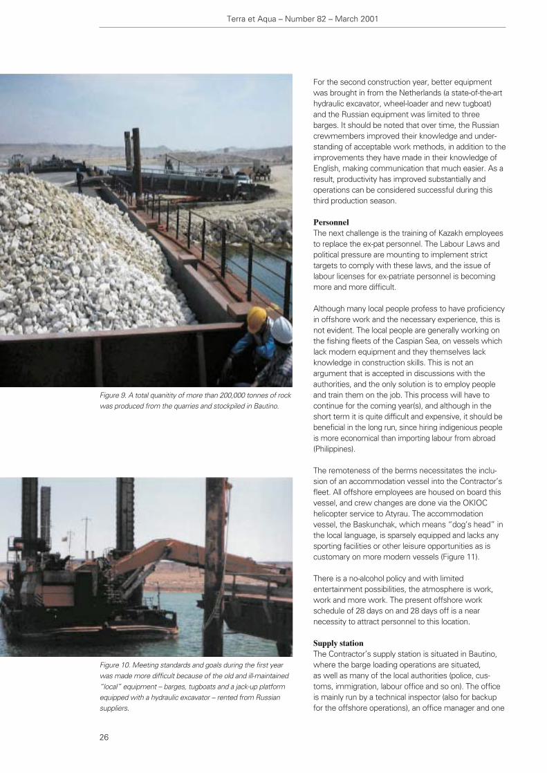
Prior to any activities, a quarry existed in the directvicinity of Bautino (Fort Shevchenko), but it could notproduce the right mix of materials for the berms. Firstrock deliveries were made from this quarry, but simul-taneously a new quarry was developed (Atash) whichwas taken into production during September 1998.Necessary preparations included the installation of a(jaw) crusher and a screening plant to produce thegraded rock as was stipulated in the contract and lateramendments (Figure 7).
All work in the quarry was subcontracted to Bechtel-Enka, a joint venture between the American companyBechtel and the Turkish company Enka. A local subcon-tractor did the actual drilling and blasting of the rock,whereas the transport of the rock to the Bautino stock-pile over a distance of approx. 11 km, was done withlocal trucks (Figure 8). At the Bautino stockpile all indi-vidual trucks had to pass a weighbridge in order toestablish the net tonnes delivered to the stockpile (ofeach gradation).
At the end of the construction year 1998, a total quanti-ty of 203,000 tonnes of rock had been produced fromthe quarries and placed on the stockpile close to theloading point in Bautino (Figure 9). The stockpile areawas created on the shore side and included a jetty andloading facility to enable the trucks to drive onto theflat-top barges. This jetty was in use by the KazakhNavy prior to 1998, but was extended further by theContractor to allow for proper mooring of the bargesand the installation of a Bailey bridge type ramp. The design was kept simple, especially since theconstruction period was estimated at six months. Now, more than two years later, the same facilities arebeing used and the contract with OKIOC has beenextended another year until October 2001, still basedon the same (but slightly modified) facilities.
THE OPERATIONS
Kashagan East (K.E.-1) is located about 40 km from thenorthern shore of the Caspian Sea, close to the KazakhCity of Atyrau. Kashagan West (K.W.) is located approx-imately 40 km to the west of Kashagan East.
Local equipmentAlthough Kashagan East was to be constructed with arelatively small quantity of rock, the time it took to build
Kazakhstan, Offshore Exploration in the Caspian Sea
25
Figure 7. The rock from the local quarry was an alluvial depositof limestone and more porous than originally thought, so anew guarry was developed.
Figure 8. The transfer of rock to the Bautino stockpile wasdone with local trucks.
For the second construction year, better equipmentwas brought in from the Netherlands (a state-of-the-arthydraulic excavator, wheel-loader and new tugboat)and the Russian equipment was limited to threebarges. It should be noted that over time, the Russiancrewmembers improved their knowledge and under-standing of acceptable work methods, in addition to theimprovements they have made in their knowledge ofEnglish, making communication that much easier. As aresult, productivity has improved substantially andoperations can be considered successful during thisthird production season.
PersonnelThe next challenge is the training of Kazakh employeesto replace the ex-pat personnel. The Labour Laws andpolitical pressure are mounting to implement stricttargets to comply with these laws, and the issue oflabour licenses for ex-patriate personnel is becomingmore and more difficult.
Although many local people profess to have proficiencyin offshore work and the necessary experience, this isnot evident. The local people are generally working onthe fishing fleets of the Caspian Sea, on vessels whichlack modern equipment and they themselves lackknowledge in construction skills. This is not anargument that is accepted in discussions with theauthorities, and the only solution is to employ peopleand train them on the job. This process will have tocontinue for the coming year(s), and although in theshort term it is quite difficult and expensive, it should bebeneficial in the long run, since hiring indigenious peopleis more economical than importing labour from abroad(Philippines).
The remoteness of the berms necessitates the inclu-sion of an accommodation vessel into the Contractor’sfleet. All offshore employees are housed on board thisvessel, and crew changes are done via the OKIOChelicopter service to Atyrau. The accommodationvessel, the Baskunchak, which means “dog’s head” inthe local language, is sparsely equipped and lacks anysporting facilities or other leisure opportunities as iscustomary on more modern vessels (Figure 11).
There is a no-alcohol policy and with limitedentertainment possibilities, the atmosphere is work,work and more work. The present offshore workschedule of 28 days on and 28 days off is a nearnecessity to attract personnel to this location.
Supply stationThe Contractor’s supply station is situated in Bautino,where the barge loading operations are situated,as well as many of the local authorities (police, cus-toms, immigration, labour office and so on). The officeis mainly run by a technical inspector (also for backupfor the offshore operations), an office manager and one
Terra et Aqua – Number 82 – March 2001
26
Figure 9. A total quanitity of more than 200,000 tonnes of rockwas produced from the quarries and stockpiled in Bautino.
Figure 10. Meeting standards and goals during the first yearwas made more difficult because of the old and ill-maintained“local” equipment -- barges, tugboats and a jack-up platformequipped with a hydraulic excavator -- rented from Russiansuppliers.
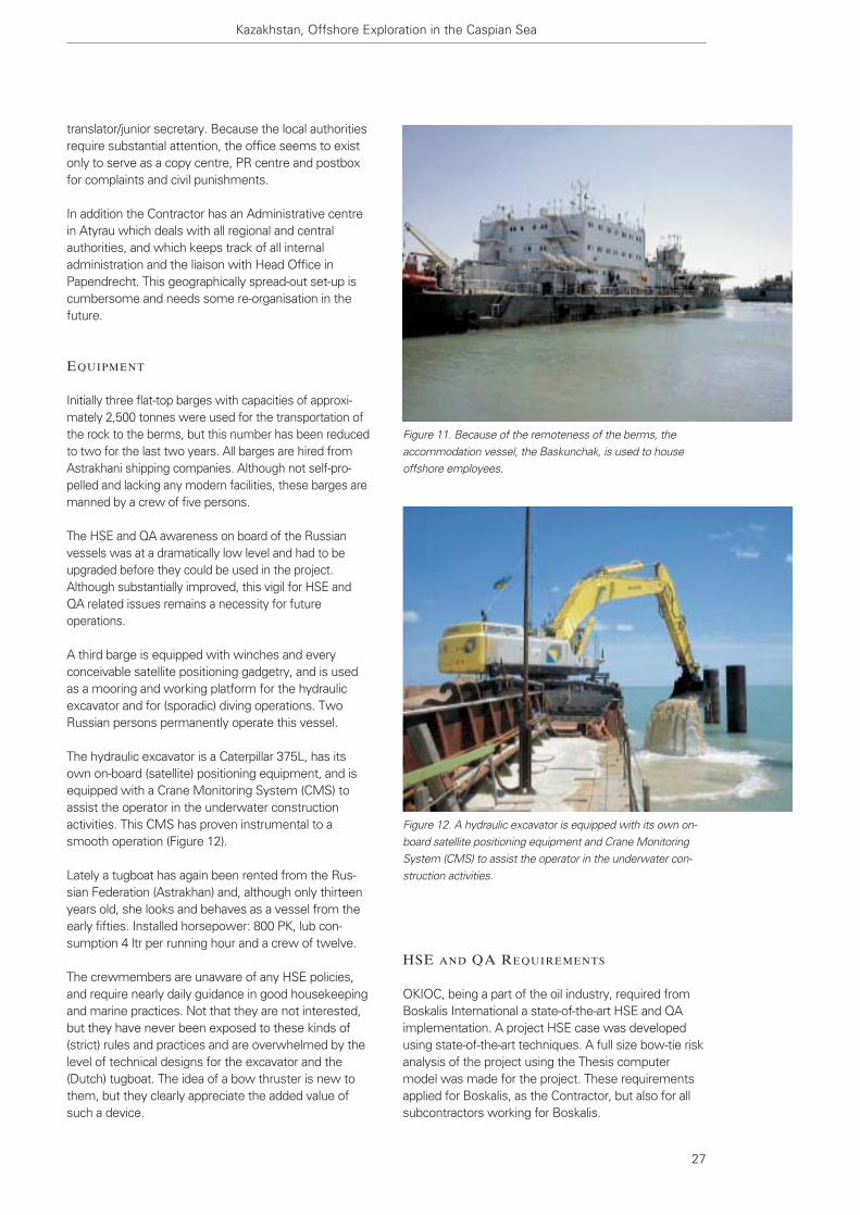
HSE AND QA REQUIREMENTS
OKIOC, being a part of the oil industry, required fromBoskalis International a state-of-the-art HSE and QAimplementation. A project HSE case was developedusing state-of-the-art techniques. A full size bow-tie riskanalysis of the project using the Thesis computermodel was made for the project. These requirementsapplied for Boskalis, as the Contractor, but also for allsubcontractors working for Boskalis.
translator/junior secretary. Because the local authoritiesrequire substantial attention, the office seems to existonly to serve as a copy centre, PR centre and postboxfor complaints and civil punishments.
In addition the Contractor has an Administrative centrein Atyrau which deals with all regional and centralauthorities, and which keeps track of all internaladministration and the liaison with Head Office inPapendrecht. This geographically spread-out set-up iscumbersome and needs some re-organisation in thefuture.
EQUIPMENT
Initially three flat-top barges with capacities of approxi-mately 2,500 tonnes were used for the transportation ofthe rock to the berms, but this number has been reducedto two for the last two years. All barges are hired fromAstrakhani shipping companies. Although not self-pro-pelled and lacking any modern facilities, these barges aremanned by a crew of five persons.
The HSE and QA awareness on board of the Russianvessels was at a dramatically low level and had to beupgraded before they could be used in the project.Although substantially improved, this vigil for HSE andQA related issues remains a necessity for futureoperations.
A third barge is equipped with winches and everyconceivable satellite positioning gadgetry, and is usedas a mooring and working platform for the hydraulicexcavator and for (sporadic) diving operations. TwoRussian persons permanently operate this vessel.
The hydraulic excavator is a Caterpillar 375L, has itsown on-board (satellite) positioning equipment, and isequipped with a Crane Monitoring System (CMS) toassist the operator in the underwater constructionactivities. This CMS has proven instrumental to asmooth operation (Figure 12).
Lately a tugboat has again been rented from the Rus-sian Federation (Astrakhan) and, although only thirteenyears old, she looks and behaves as a vessel from theearly fifties. Installed horsepower: 800 PK, lub con-sumption 4 ltr per running hour and a crew of twelve.
The crewmembers are unaware of any HSE policies,and require nearly daily guidance in good housekeepingand marine practices. Not that they are not interested,but they have never been exposed to these kinds of(strict) rules and practices and are overwhelmed by thelevel of technical designs for the excavator and the(Dutch) tugboat. The idea of a bow thruster is new tothem, but they clearly appreciate the added value ofsuch a device.
Kazakhstan, Offshore Exploration in the Caspian Sea
27
Figure 11. Because of the remoteness of the berms, theaccommodation vessel, the Baskunchak, is used to houseoffshore employees.
Figure 12. A hydraulic excavator is equipped with its own on-board satellite positioning equipment and Crane MonitoringSystem (CMS) to assist the operator in the underwater con-struction activities.
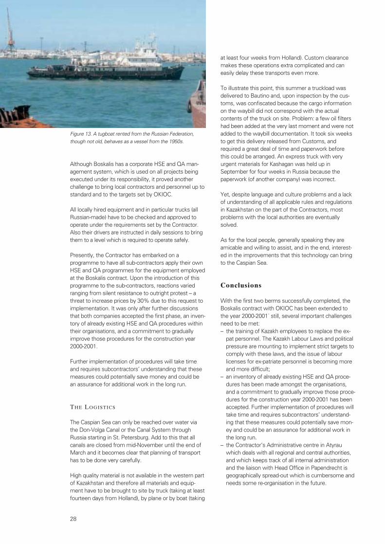
Although Boskalis has a corporate HSE and QA man-agement system, which is used on all projects beingexecuted under its responsibility, it proved anotherchallenge to bring local contractors and personnel up tostandard and to the targets set by OKIOC.
All locally hired equipment and in particular trucks (allRussian-made) have to be checked and approved tooperate under the requirements set by the Contractor.Also their drivers are instructed in daily sessions to bringthem to a level which is required to operate safely.
Presently, the Contractor has embarked on aprogramme to have all sub-contractors apply their ownHSE and QA programmes for the equipment employedat the Boskalis contract. Upon the introduction of thisprogramme to the sub-contractors, reactions variedranging from silent resistance to outright protest – athreat to increase prices by 30% due to this request toimplementation. It was only after further discussionsthat both companies accepted the first phase, an inven-tory of already existing HSE and QA procedures withintheir organisations, and a commitment to graduallyimprove those procedures for the construction year2000-2001.
Further implementation of procedures will take timeand requires subcontractors’ understanding that thesemeasures could potentially save money and could bean assurance for additional work in the long run.
THE LOGISTICS
The Caspian Sea can only be reached over water viathe Don-Volga Canal or the Canal System throughRussia starting in St. Petersburg. Add to this that allcanals are closed from mid-November until the end ofMarch and it becomes clear that planning of transporthas to be done very carefully.
High quality material is not available in the western partof Kazakhstan and therefore all materials and equip-ment have to be brought to site by truck (taking at leastfourteen days from Holland), by plane or by boat (taking
at least four weeks from Holland). Custom clearancemakes these operations extra complicated and caneasily delay these transports even more.
To illustrate this point, this summer a truckload wasdelivered to Bautino and, upon inspection by the cus-toms, was confiscated because the cargo informationon the waybill did not correspond with the actualcontents of the truck on site. Problem: a few oil filtershad been added at the very last moment and were notadded to the waybill documentation. It took six weeksto get this delivery released from Customs, andrequired a great deal of time and paperwork before this could be arranged. An express truck with veryurgent materials for Kashagan was held up inSeptember for four weeks in Russia because thepaperwork (of another company) was incorrect.
Yet, despite language and culture problems and a lackof understanding of all applicable rules and regulationsin Kazakhstan on the part of the Contractors, mostproblems with the local authorities are eventuallysolved.
As for the local people, generally speaking they areamicable and willing to assist, and in the end, interest-ed in the improvements that this technology can bringto the Caspian Sea.
Conclusions
With the first two berms successfully completed, theBoskalis contract with OKIOC has been extended tothe year 2000-2001˙ still, several important challengesneed to be met:– the training of Kazakh employees to replace the ex-
pat personnel. The Kazakh Labour Laws and politicalpressure are mounting to implement strict targets tocomply with these laws, and the issue of labourlicenses for ex-patriate personnel is becoming moreand more difficult;
– an inventory of already existing HSE and QA proce-dures has been made amongst the organisations,and a commitment to gradually improve those proce-dures for the construction year 2000-2001 has beenaccepted. Further implementation of procedures willtake time and requires subcontractors’ understand-ing that these measures could potentially save mon-ey and could be an assurance for additional work inthe long run.
– the Contractor’s Administrative centre in Atyrauwhich deals with all regional and central authorities,and which keeps track of all internal administrationand the liaison with Head Office in Papendrecht isgeographically spread-out which is cumbersome andneeds some re-organisation in the future.
28
Figure 13. A tugboat rented from the Russian Federation,though not old, behaves as a vessel from the 1950s.
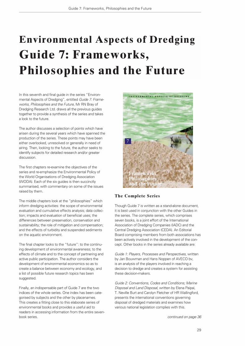
Guide 7: Frameworks, Philosophies and the Future
29
In this seventh and final guide in the series “Environ-mental Aspects of Dredging”, entitled Guide 7: Frame-works, Philosophies and the Future, Mr RN Bray ofDredging Research Ltd. draws all the previous guidestogether to provide a synthesis of the series and takesa look to the future.
The author discusses a selection of points which havearisen during the several years which have spanned theproduction of the series. These points may have beeneither overlooked, unresolved or generally in need ofairing. Then, looking to the future, the author seeks toidentify subjects for detailed research and/or greaterdiscussion.
The first chapters re-examine the objectives of theseries and re-emphasize the Environmental Policy ofthe World Organisations of Dredging Association(WODA). Each of the six guides is then succinctlysummarised, with commentary on some of the issuesraised by them.
The middle chapters look at the “philosophies” whichinform dredging activities: the scope of environmentalevaluation and cumulative effects analysis; data collec-tion; impacts and evaluation of beneficial uses; thedifferences between preservation, conservation andsustainability; the role of mitigation and compensation;and the effects of turbidity and suspended sedimentson the aquatic environment.
The final chapter looks to the “future”: to the continu-ing development of environmental awareness; to theeffects of climate and to the concept of partnering andactive public participation. The author considers thedevelopment of environmental economics so as tocreate a balance between economy and ecology, and a list of possible future research topics has beensuggested.
Finally, an indispensable part of Guide 7 are the twoindices of the whole series. One index has been cate-gorised by subjects and the other by placenames. This creates a fitting close to this elaborate series ofenvironmental books and provides a useful aid toreaders in accessing information from the entire seven-book series.
Environmental Aspects of Dredging
Guide 7: Frameworks,Philosophies and the Future
The Complete Series
Though Guide 7 is written as a stand-alone document,it is best used in conjunction with the other Guides inthe series. The complete series, which comprisesseven books, is a joint effort of the InternationalAssociation of Dredging Companies (IADC) and theCentral Dredging Association (CEDA). An EditorialBoard comprising members from both associations hasbeen actively involved in the development of the con-cept. Other books in the series already available are:
Guide 1: Players, Processes and Perspectives, writtenby Jan Bouwman and Hans Noppen of AVECO bv, is an analysis of the players involved in reaching adecision to dredge and creates a system for assistingthese decision-makers.
Guide 2: Conventions, Codes and Conditions; MarineDisposal and Land Disposal, written by Elena Paipai, T. Neville Burt and Carolyn Fletcher of HR Wallingford,presents the international conventions governingdisposal of dredged materials and examines howvarious national legislation complies with this.
continued on page 36
E N V I R O N M E N T A L A S P E C T S O F D R E D G I N G
7
Frameworks,Philosophiesand the Future
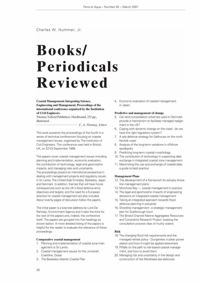
4. Economic evaluation of coastal management in Japan.
Predictive and management of change5. Can land consolidation schemes used in Denmark
provide a mechanism to facilitate managed realign-ment in the UK?
6. Coping with dynamic change on the coast - do wehave the right regulatory system?
7. A sea defence strategy for Salthouse on the northNorfolk coast
8. Analysis of the long-term variations in offshoresandbanks
9. Predicting long-term coastal morphology10. The contribution of technology in supporting data
exchange in integrated coastal zone management11. Maximising the use and exchange of coastal data:
a guide to best practice
Management Plans12. The development of a framework for estuary shore-
line management plans13. Montrose Bay — coastal management in practice14. The legal and geomorphic impacts of engineering
decisions on integrated coastal management15. Taking an integrated approach towards flood
defence planning in estuaries16. Shoreline management - a strategic management
plan for Scarborough town17. The Bristol Channel Marine Aggregates Resources
and Constraints Research Project: keeping theconsultation process clear of murky waters
Risk18. The changing flood risk requirements and the
managed retreat policy - Dungeness nuclear powerstation and how it might be applied elsewhere
19. Pitfalls on the path to risk-based coastal manage-ment, and how to avoid them
20. Managing risk and uncertainty in the design andconstruction of the Minehead sea defences
Coastal Management: Integrating Science,Engineering and Management. Proceedings of theinternational conference organised by the Institutionof Civil Engineers. Thomas Telford Publishers. Hardbound, 252 pp.,illustrated.
C. A. Fleming, Editor
This book presents the proceedings of the fourth in aseries of technical conferences focusing on coastalmanagement issues, organised by The Institution ofCivil Engineers. This conference was held in Bristol,UK, on 22-23 September 1999.
The papers cover coastal management issues includingplanning and implementation, economic evaluation, the contribution of technology, legal and geomorphicimpacts, and managing risks and uncertainty. The proceedings present an international perspective indealing with management projects and regulatory issuesin Sri Lanka, The United Arab Emirates, Barbados, Japanand Denmark. In addition, themes that will have futureconsequences such as the UK’s flood defence aims,objectives and targets, and the need for a Europeandirective for coastal management are also included.About twenty pages of discussion follow the papers.
The initial paper is a keynote address by Lord DeRamsey, Environment Agency and it sets the tone forthe rest of the papers and, indeed, the conferenceitself. The papers are grouped into five headings asshown below. A more detailed listing of the papers ishelpful for the reader to evaluate the relevance of these proceedings.
Comparative coastal management1. Planning and implementation of coastal zone man-
agement is Sri Lanka2. Coastal management issues for the Jumeirah
Coastline, Dubai3. The Barbados Atlantic Coastal Plan
Charles W. Hummer, Jr.
Books/PeriodicalsReviewed
Terra et Aqua – Number 82 – March 2001
30

Books/Periodicals Reviewed
31
Into the next millennium21. Does coastal management require a European
directive? The advantages and disadvantages of a non-statutory approach
22. Tourism and resort action plans - identifying amethodology
23. Flood and coastal defence aims, objectives andtargets
Although a number of the papers contain relevantmaterial and issues related to dredging and port andwaterway issues, several seem to warrant specialmention. Mannion’s paper, “Montrose Bay - CoastalManagement in Practice”, highlights the beneficial useof dredged material as an effective tool for coastalmanagement. Another paper with wider implications isthe paper by Jewell, Roberts and McInnes on the needor lack thereof of a European Directive related tocoastal management; and raises the question ofwhether actions should be voluntary or imposed.
As is usually the case with The Institution of Civil Engineers publications, the book is well produced andattractively bound.
This publication may be obtained from:Thomas Telford PublishingThomas Telford Ltd.1 Heron Quay, London E14 4JD, UK
ASCE Press1801 Alexander Bell DriveReston, Virginia 20191-4400, USA
Maruzen Co. Ltd. Book Department3-10 Nihonbashi 2-chomeChuo-hu, Tokyo 103, Japan
DA Books and Journals648 Whitehorse RoadMitcham 3132, Victoria, Australia
Port Technology International, Eleventh Edition, The Review of Advanced Technologies for Ports and Terminals Worldwide.London, UK. softbound, 246 pp., A-4 size, colour illustrated.
IGC Publishing Ltd
This glossy soft-covered publication has a contempo-rary magazine-like presentation. Its stated audience isport directors and terminal operators and its subjectmatter covers technical, operational and managementissues. It is published twice a year, in May and inNovember and contains a fair number of advertisements.
This eleventh edition is divided into seven sections with
a number of articles in each of the sections. The sec-tions and articles seem to present current information.
Section 1 - Vessel Traffic Systems– VTS Keeps Moving– Systems for the Display and Processing of AIS
Transponder Information– Vessel Traffic Management Systems for Inland
Waterways in the Netherlands– An Enhanced Vessel Traffic Management System
for the Panama Canal– Vessel Traffic Services (VTS) System for the River
Waal
Section 2 - Mooring and Berthing– Steel Pile Corrosion Survey Model- Inspection
Procedures for Accelerated Corrosion on MarineSteel Piles
– Berthing Aids - A Complete Solution– Escorting Ships with Tractor Tugs
Section 3 - Container Inspection– Recent Developments in X-ray Systems for Air-Cargo– HCV- Mobile Power and Flexibility– Full Cargo Inspection Possible Through Recent
Technology Advances– Container Code Reading System
Section 4 - Container Handling– 30 Years On- Crane Rail Fixings Past,
Present and Future– Upgrading Old Rubber Tyred Gantry Cranes– Coping with Container Gantry Cranes Wheel Loads– Hydraulic Drives versus Electric Drives in Harbour
Mobile Cranes– Crane Retrofitting- Optimal Control Without a
Programmable Logic Controller– Replacement of Drum Brakes with Calliper
Disc Brakes– Reliability Considerations for Electrical Equipment
on Harbour Cranes– Refurbishment of Container Crane Operator
Consoles
Section 5- Terminal Equipment– Michelin Tyres Reduce Operating Costs at Ports– Shipping Newsprint to Japan Damage Free– More Performance and Speed for Container
Handling by an Innovation- Side Reach Stacker ML 5016 SR
– Safety for RoRo Tractors
Section 6 - Bulk Handling and Hazardous Chemicals– Floating Terminals: A Logistic Solution in the Dry-
Bulk Trade- Coal Handling in the Lake of Maracaibo– Economic Clinker Import Terminal
continued on page 36
Oceanology International 2001 AmericasMiami Beach Convention Center,
Miami Beach, Florida, USAApril 3-5 2001
The first OI Americas exhibition and conference will beheld in April 2001 and will be held biennially thereafter.It is set to become a joint ocean forum bringing togeth-er all sides of industry, science, research, governmentand academia, with a natural focus on the opportunitiesfacing the Americas. As a transportation hub handling60% of airline traffic between the Americas, Miami hasbeen chosen for ease of travel for the global oceancommunity as well as for the concentrations of oceanscience and technology institutions in Florida.
For further information please contact:In the Americas:Kari Jacobson, OI AmericasPGI/Spearhead, PGI Inc,2200 Wilson Boulevard, Ste. 200Arlington, VA 22201-3324, USAtel. +1 703 312 9129, fax +1 703 528 1724
For other countries:Jane Blinkenberg, OI AmericasPGI/Spearhead, Spearhead Exhibitions Ltd,Ocean House, 50 Kingston Road,New Malden, Surrey KT3 3LZ, United Kingdomtel. +44 181 949 9813 or 949 9222,fax +44 181 949 8186email: [email protected]
22nd IAPH World Ports ConferenceQueen Elizabeth Hotel, Montreal, Canada
May 19-26 2001
This first IAPH conference of the new millenium willhighlight the renewed and revitalised maritime industry.Organised in cooperation with the Montreal PortAuthority, the conference will focus on the future of themaritime sector. The conference will include a tradeshow which will also be held at the conference site.
WODCON XVI and ExhibitionHotel Shangri-la,
Kuala Lumpur, MalaysiaApril 2-5 2001
The Sixteenth World Dredging Congress and Exhibitionwill be entitled “Dredging for Prosperity; AchievingSocial and Economic Benefits”. New ways of dredgingand handling dredged materials are continually beingfound. These need to be promoted in order to achievesocial and economic benefits. Papers showing thebenefit/cost relationship of dredging works are espe-cially encouraged, including new forms of dredging,developments in education and training, case studiesand other developments in the industry.
An international exhibition will be held in conjunctionwith the conference. In addition, a technical visit toPaya Indah, Malaysia’s prestigious wetland sanctuarywill be featured. For up-to-date and detailed informationvisit the WODA website at http://www.woda.org.
For further information, please contact:Congress SecretariatExpo Age International (M) Sdn Bhd, Wisma Pico,19-20 Jalan Tembaga SD5/2, Bandar Sri Damansara,52200 Kuala Lumpur, Malaysiatel. +603 635 5535, fax +603 6353231email: [email protected]
EADA Secretariat, John DobsonGPO Box 388, Hamilton Central,Qld 4007, Australiatel/fax +61 7 3262 3834email: [email protected], or
CEDA Secretariat, Anna CsitiPO Box 488, 2600 AL Delft, The Netherlandstel. +31 15 278 3145, fax +31 15 278 7104email: [email protected]
Seminars/Conferences/Events
Terra et Aqua – Number 82 – March 2001
32
Seminars/Conferences/Events
33
For more information please contact:Lafleur Communication Marketing Inc.500 Place d’Armes, Suite 2110Montreal, Quebec, Canada H2Y 2W2fax: +1 514 288 2601email: [email protected] or the following websites:Government of Canada: canada.gc.caGovernmennt of Quebec: www.gouv.qc.caCity of Montreal: www.ville.montreal.qc.caIAPH: www.iaph.or.jpMontreal Port Authority: www.port-montreal.com
WEDA and Texas A&M 33rd Annual DredgingSeminar and Exhibition
Wyndham Greenspoint Hotel, Houston, Texas, USA
June 24-28 2001
The conference is an opportunity for an exchange ofthoughts by dredging contractors, ports, engineeringservices, environmentalists and environmental consul-tants, US Corps of Engineers, Environmental ProtectionAgency, Fish and Wild Life Services and members ofacademia. It provides an opportunity to keep up withthe changing Technology and Regulatory issues facingthe dredging industry. In addition a special “Call for Student Papers” is beingissued. WEDA will wave the conference registrationfee for student paper presenters and provide them a$500 reimbursement toward expenses. For considera-tion the paper should be solely written by a studentwith no co-authors.To accommodate the PIANC session, the conferencehas been extended a half day, and on the last day,there will be a post-convention tour to the HoustonChannel ship channel deepening project.
For further information please contact:WEDA Executive Offices tel. +1 360 750 0209email: [email protected]
Coastal Zone 01Cleveland, Ohio USA
July 15-19 2001
Cleveland is a Great Lakes coastal city and the confer-ence will notably address coastal and ocean manage-ment concerns. It will feature important lessons learnedby coastal managers around the world and models ofsuccessful partnerships such as that established in theGreat Lakes, where two sovereign nations jointly man-age water and living resources of this great “inland sea”.The overriding theme will be to examine creative urbanplanning strategies, fiscal incentives, innovative policiesand other techniques to hinder urban sprawl along
ocean and inland coasts and to achieve instead “smartgrowth” in coastal communities.
For further information contact:Jan Kucklick, NOAA Coastal Services Center2234 South Hobson AvenueCharleston, South Carolina 29405 USAtel. +1 843 740 1279, fax +1 843 740 [email protected]
1st International Congress of Seas and OceansSzczecin Maritime University
Szczecin and Mi™dzyzdroje, PolandSeptember 18-23 2001
On behalf of the best Pomeranian University RectorsConference this congress is being organised toexchange ideas and experiences in the field of sustain-able use of maritime resources for the development ofhumanity. The following topics are within the scope ofthe congress:– research of seas and oceans (waves, currents,
chemical, biological and lithodynamic processes);– oceans and seas as sources of food and energy;– mineral resources under sea (including crude oil and
natural gas);– sea transport including waterways, ships, ports and
port management;– protection of the sea environment;– seas and oceans for recreation and sports; and– maritime policy of coastal states (legal aspects,
organisation of maritime administration and rescue).
For further information please contact:Seas and Oceans Congress Secretariat:att: Dr inz. JarosΩaw GuziewiczWyzsza SzkoΩ MorskaUl. WaΩy Chrobrego 1/2, 70 – 500 Szczecin, Polandtel. +48 91 434 42 26, ext. 329tel./fax +48 91 489 4003email: [email protected]
NEVASt. Petersburg, RussiaSeptember 24-28 2001
This 6th NEVA Exhibition celebrates the revival ofRussia’s shipping, shipbuilding, offshore energy, portdevelopment, fisheries, and oceanography and oceanexploration sectors. The current modernisation of thecommercial environment with the introduction ofclearer operating regulations, laws and tax codes willincrease investment and business. Two new majorinitiatives will be: – the NEVA Capital Cruise Shipping in the Baltic,

– laboratory geoenvironmental testing related to soft soil;
– land reclamation problems;– waste ponds/tailings dams design; and– case histories.
There will be a technical visit to observe the mostadvanced underwater geoenvironmental technologiesused in the Antwerp area as well as some soil remedia-tion facilities.
For further information contact:The Organising Committee of GEG 2001Laboratory of Soil MechnaicsProf. W.F. Van ImpeTechnologiepark 9, 9052 Zwijnaarde, Belgiumtel. +32 9 264 5717 (23), fax +32 9 264 5849email: [email protected]/~wvanimpe
Sea-Port 2001BUEXCO, Busan, Korea
October 30-November 3 2001
This is Korea’s primary exhibition of international port,logistics and environmental technology, simultaneouslyheld with KOMARINE and Naval & Defence under the umbrella of Marine Week 2001. The show isauthorised by the Ministry of Commerce, Industry andEnergy and the Ministry of Maritime Affairs andFisheries. Top quality port-related industry products,logistics technology and environmental protectionsystems will be exhibited.
For further information please contact:Sea-Port 2001 Show Management Office, Rm. 501,Kumsan Bld., 17-1 Yoido-dongYongdeungpo-ku, Seoul 150-010, Koreatel. +82 2 785 4771, fax +82 2 785 6117/8email: [email protected]
Europort 2001RAI Conference Centre,
Amsterdam, The NetherlandsNovember 13-17 2001
The Europort 2001 Exhibition is one of the largest world-wide trade shows for the international maritime industry.Exhibitors include all branches of the maritime industryfrom shipbuilding, to suppliers of technical and safetyequipment, port authorities, port management anddevelopment, offshore and dredging industries. Visitors encompass a broad range of people in relatedindustries, science, research, government and academia.
For further information contact:Mr Farouk Nefzi, Project Manager, Europort 2001
Black Sea, Arctic and Pacific Regions and for inlandWaterways; and
– NEVA Capital Ports, a programme to increase thevelocity and volumes of passenger and cargo traffic.
For further information please contact:Dolphin Exhibitions112 High Street, Bildeston,Suffolk IP7 7EB, UKtel. +44 1449 741801, fax: +44 1449 741628email: [email protected]/neva
India International Maritime Expo (INMEX) 2001Mumbai (Bombay), India
October 10-13 2001
The second India International Maritime Expo (INMEX)will provide an opportunity for overseas companies toenter the maritime market in India and to meet withrepresentatives from government such as the Ministriesof Surface Transport (MoST) and Defence, and the Coast Guard.The MoST is responsible for policies for the development of modes of transport including themaritime sector.
In order to decongest the present major port facilitiesthe MoST has launched an ambitious plans for infra-structure development in the port sector, the shipbuild-ing industry and inland water transport. Private invest-ments are being encouraged for port development aswell as ship building and repair.
For further information contact:INMEX SecretariatPradeep Deviah & AssociatesNor. 35, Gover Road, Cox Town,Bangalore 560 005, India tel. +91 80 54 84 155/ 54 84 389fax +91 80 54 85 214email: [email protected] www.inmexindia.com
Ghent Environmental GeotechnicsUniversity of Ghent, Belgium
October 29-31 2001
GEG 2001, a specialty conference on underwatergeoenvironmental issues, is presented in cooperationwith ISSMGE Technical Committee 5, Laboratory ofSoil Mechanics. Main conference topics include:– environmental dredging and related technologies;– underwater ground improvement, including soft
soil consolidation issues;– in situ and off situ remediation of dredged material– (bio)chemical phenomena related to soft soil
mechanics;
Terra et Aqua – Number 82 – March 2001
34

Seminars/Conferences/Events
35
Amsterdam RAI, PO Box 777771070 Amsterdam, The Netherlandstel. +31 20 549 1212, fax +31 20 546 4469email: [email protected]
Port China & Marintec ChinaIntex Shanghai, China
December 4-7 2001
China’s premier maritime conference and exhibition,Marintec China, will now include Port China. CurrentlyChina has over 2000 ports and 128 ports which areopen to foreign vessels. Many ports are already beingupgraded and increased trade is expected to comeform China’s entry into the WTO. The port authoritiesof Shanghai and Rotterdam have signed a letter ofintent to cooperate on technology interchange. PortChina will address the demand for better and moreexpedient ort facilities and services and will benefitfrom running concurrently with Marintec China. Highlevel seminars and the Senior Maritime Forum willallow policy makers and industry leaders a chance toexchange views.
For further information please contact:Ms Ginnie Koay in Hong Kong, email: [email protected] Wang Lingzhi in Shanghai,email: [email protected] Richard Johnson,email: [email protected] Michael Kazakoff, Miller Freemanemail: [email protected]
Call for PapersCEDA Dredging Days
RAI Conference CentreAmsterdam, The Netherlands
November 15 2001
"Dredging Seen; Perspectives, from the Outside LookingIn” is the theme of the CEDA Dredging Day 2001 to beheld during Europort Exhibition. How do people andorganisations from outside the dredging world look atus? Do they know what dredging is? And if they areaware, does it provide the services required? To explorethese questions CEDA has invited notable speakers fromoutside the world of dredging to offer their perspectiveson dredging.
CEDA is also holding a substantive programme, “The Academic Hour”, in which university and college
students and young faculty are asked to present theirresearch on any matter related to dredging. Abstracts should be a maximum 300 words.In addition, CEDA is issuing a “Call for a Dredging Song”.It is not meant to be taken too seriously but may beinformative, evocative, humourous or emotional. All isthe spirit of good fun.
For further information and to submit abstracts andlyrics contact:CEDA SecretariatPO Box 488, 2600 AL Delft,The Netherlandstel. +31 15 278 3145fax +31 15 278 7104email: [email protected]
30th PIANC Navigation CongressSydney, Australia
September 22-26 2002
PIANC will be focusing on the following topics: – How to guarantee sustainable navigation; – Environmental issues; – Policy issues, such as the role of public and private
sectors in port development; – Inland waterways transport; – Port issues; and – Issues related to ships and fairways.
Abstracts should be submitted by April 1, 2001 and belimited to two pages double spaced.They may be emailed or sent by post to the addressbelow. Fax submissions are not acceptable.Acceptance notification will be by August 1, 2001. Final papers should be submitted by February 1, 2002.
For further information or to submit an abstract:PIANC, General SecretariatGraaf de Ferrairis - 11th Flr.20, Boulevard du Roi Albert II,1000 Brussels, Belgiumtel. +32 2 553 7160, +32 2 553 7155email: [email protected]
continued from page 36
– The Rotary Belt Discharger- Successfully Used forAlmost 20 Years
– New Lemniscate Floating Grab Crane– Safe Berthing of Liquid Gas Carrier– What’s That Smell? A Case Study on Odour
Elimination from Crude Tanker Loading– Petrocare Vapour Processing System
Section 7 - Port and Terminal Management– Risk Based Safety Management Systems for
Navigation in Ports– Real Time - The Ultimate Price– Mega-terminals, Trends and Issues
Section 8- Port Planning and Construction– Section Foreward – CEDA– How the Global Positioning System (GPS) and
Software Systems are Used on Major MarineConstruction Projects
– Water Injection Dredging in Hamburg- Applicationand Research
– Effective Use of Jumbo Hopper Dredgers in MajorPort Expansion Projects
– Water Jet Technologies Offer New Power andAccuracy
– United Marine International (UMI) Commissions aNew Generation of Trash Skimmer Vessels
– High Accuracy Dredging of Contaminated Sediments: Cleaning up Lake Ketelmeer
Whilst there are a number of non-dredging relatedpapers that have broad interest to readers, those thatfocus on dredging are of particular relevance. It isencouraging to see that some of the more innovativedredging initiatives are getting disseminated to the portand terminal community˙ successes such as thatdocumented at Lake Ketelmeer and the use of water jetsand water injection dredging are appropriately high-lighted. Likewise the increasing use of GPS in dredgingprojects is another area where increased visibility iswarranted.
Whilst the publication is more commercial in its orienta-tion, it reaches an audience where many of thesesubjects might not otherwise be surfaced. In thatsense the publication provides a valuable service anddeserves the reader’s attention. The twelfth edition isscheduled to be published in May 2001.
The publication can be requested from:ICG Publishing Ltd.14 Greville StreetLondon ECIN 8SB, UKTel. +44 2078710123Fax +44 2078710101Email: [email protected]
Terra et Aqua – Number 82 – March 2001
36
continued from page 29
Guide 3: Investigation, Interpretation, and Impact,written by Richard K. Peddicord and Thomas M. Dillon,independent consultants, describes pre-dredging inves-tigations for material characterisation. This includesfield surveys, sampling and laboratory testing for physi-cal, chemical and biological characteristics of dredgedmaterials.
Guide 4: Machines, Mitigation and Monitoring, writtenby Jos Smits, General Manager of International Marine& Dredging Consultants NV, discusses dredgingequipment, mitigating measures and the monitoringand control of the dredging process.
Guide 5: Reuse, Recycle or Relocate,written by AnnaCsiti, General Manager of the Central Dredging
Association, and T. Neville Burt, Principal Engineer atHR Wallingford, addresses the question, “What shouldbe done with removed sediment?”. The book reflectsthe concern of the public and the industry with thedestination of the millions of cubic metres of dredgedsediments which arise each year.
Guide 6: Effects, Ecology and Economy, written by Mr Anders Jensen and Mr Bo Mogensen of DHI Water& Environment, presents the environmental and socio-economic effects related to dredging and/or reclama-tion projects.
The entire series or individual books in the series maybe ordered from the IADC Secretariat in The Hague.
Guide 7: Frameworks,Philosophies and the Future
Books/Periodicals Reviewed
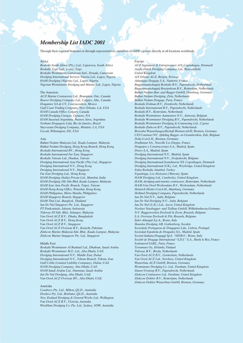
AfricaBoskalis South Africa (Pty.) Ltd., Capetown, South AfricaBoskalis Togo Sarl., Lomé, TogoBoskalis Westminster Cameroun Sarl., Douala, CamerounDredging International Services Nigeria Ltd., Lagos, NigeriaHAM Dredging (Nigeria) Ltd., Lagos, NigeriaNigerian Westminster Dredging and Marine Ltd., Lagos, Nigeria
The AmericasACZ Marine Contractors Ltd., Brampton, Ont., CanadaBeaver Dredging Company Ltd., Calgary, Alta., CanadaDragamex SA de CV, Coatzacoalcos, MexicoGulf Coast Trailing Company, New Orleans, LA, USAHAM Canada Office, Calgary, CanadaHAM Dredging Curaçao, Curaçao, NAHAM Sucursal Argentinia, Buenos Aires, ArgentinaNorham Dragagens Ltda, Rio de Janeiro, BrazilStuyvesant Dredging Company, Metairie, LA, USAUscodi, Wilmington, DE, USA
AsiaBallast Nedam Malaysia Ltd., Kuala Lumpur, MalaysiaBallast Nedam Dredging, Hong Kong Branch, Hong KongBoskalis International BV., Hong KongBoskalis International Far East, SingaporeBoskalis Taiwan Ltd., Hualien, TaiwanDredging International Asia Pacific (Pte) Ltd., SingaporeDredging International N.V., Hong KongDredging International N.V., SingaporeFar East Dredging Ltd., Hong KongHAM Dredging (India) Private Ltd., Mumbai, IndiaHAM Dredging (M) Sdn Bhd, Kuala Lumpur, MalaysiaHAM East Asia Pacific Branch, Taipei, TaiwanHAM Hong Kong Office, Wanchai, Hong KongHAM Philippines, Metro Manila, PhilippinesHAM Singapore Branch, SingaporeHAM Thai Ltd., Bangkok, ThailandJan De Nul Singapore Pte. Ltd., SingaporePT Penkonindo, Jakarta, IndonesiaTideway DI Sdn. Bhd., Selangor, MalaysiaVan Oord ACZ B.V., Dhaka, BangladeshVan Oord ACZ B.V., Hong KongVan Oord ACZ B.V., SingaporeVan Oord ACZ Overseas B.V., Karachi, PakistanZinkcon Marine Malaysia Sdn. Bhd., Kuala Lumpur, MalaysiaZinkcon Marine Singapore Pte. Ltd., Singapore
Middle EastBoskalis Westminster Al Rushaid Ltd., Dhahran, Saudi ArabiaBoskalis Westminster M.E. Ltd., Abu Dhabi, UAEDredging International N.V., Middle East, DubaiDredging International N.V., Tehran Branch, Tehran, IranGulf Cobla (Limited Liability Company), Dubai, UAEHAM Dredging Company, Abu Dhabi, UAEHAM Saudi Arabia Ltd., Damman, Saudi ArabiaJan De Nul Dredging, Abu Dhabi, UAEVan Oord ACZ Overseas BV., Abu Dhabi, UAE
AustraliaCondreco Pty. Ltd., Milton, QLD., AustraliaDredeco Pty. Ltd., Brisbane, QLD., AustraliaNew Zealand Dredging & General Works Ltd., WellingtonVan Oord ACZ B.V., Victoria, AustraliaWestHam Dredging Co. Pty. Ltd., Sydney, NSW, Australia
EuropeACZ Ingeniører & Entreprenører A/S, Copenhagen, DenmarkAnglo-Dutch Dredging Company Ltd., Beaconsfield,United KingdomA/S Jebsens ACZ, Bergen, NorwayAtlantique Dragage S.A., Nanterre, FranceBaggermaatschappij Boskalis B.V., Papendrecht, NetherlandsBaggermaatschappij Breejenbout B.V., Rotterdam, NetherlandsBallast Nedam Bau- und Bagger GmbH, Hamburg, GermanyBallast Nedam Dredging, Zeist, NetherlandsBallast Nedam Dragage, Paris, FranceBoskalis Dolman B.V., Dordrecht, NetherlandsBoskalis International B.V., Papendrecht, NetherlandsBoskalis B.V., Rotterdam, NetherlandsBoskalis Westminster Aannemers N.V., Antwerp, BelgiumBoskalis Westminster Dredging B.V., Papendrecht, NetherlandsBoskalis Westminster Dredging & Contracting Ltd., CyprusBoskalis Zinkcon B.V., Papendrecht, NetherlandsBrewaba Wasserbaugesellschaft Bremen mbH, Bremen, GermanyCEI Construct NV, Afdeling Bagger- en Grondwerken, Zele, BelgiumDelta G.m.b.H., Bremen, GermanyDraflumar SA., Neuville Les Dieppe, FranceDragados y Construcciones S.A., Madrid, SpainDravo S.A., Madrid, SpainDredging International N.V., Madrid, SpainDredging International N.V., Zwijndrecht, BelgiumDredging International Scandinavia NS, Copenhagen, DenmarkDredging International (UK), Ltd., Weybridge, United KingdomEnka-Boskalis, Istanbul, TurkeyEspadraga, Los Alcázares (Murcia), SpainHAM Dredging Ltd., Camberley, United KingdomHAM, dredging and marine contractors, Rotterdam, NetherlandsHAM-Van Oord Werkendam B.V., Werkendam, NetherlandsHeinrich Hirdes G.m.b.H., Hamburg, GermanyHolland Dredging Company, Papendrecht, NetherlandsJan De Nul N.V., Aalst, BelgiumJan De Nul Dredging N.V., Aalst, BelgiumJan De Nul (U.K.) Ltd., Ascot, United KingdomNordsee Nassbagger- und Tiefbau GmbH, Wilhelmshaven,GermanyN.V. Baggerwerken Decloedt & Zoon, Brussels, BelgiumS.A. Overseas Decloedt & Fils, Brussels, BelgiumSider-Almagià S.p.A., Rome, ItalySkanska Dredging AB, Gothenborg, SwedenSociedade Portuguesa de Dragagens Lda., Lisbon, PortugalSociedad Española de Dragados SA., Madrid, SpainSocietà Italiana Dragaggi SpA. “SIDRA”, Rome, ItalySociété de Dragage International “S.D.I.” S.A., Marly le Roi, FranceSodranord SARL, Paris, FranceTerramare Oy, Helsinki, FinlandTideway B.V., Breda, NetherlandsVan Oord ACZ B.V., Gorinchem, NetherlandsVan Oord ACZ Ltd., Newbury, United KingdomWasserbau ACZ GmbH, Bremen, GermanyWestminster Dredging Co. Ltd., Fareham, United KingdomZanen Verstoep B.V., Papendrecht, NetherlandsZinkcon Contractors Ltd., Fareham, United KingdomZinkcon Dekker B.V., Rotterdam, NetherlandsZinkcon Dekker Wasserbau GmbH, Bremen, Germany
Membership List IADC 2001Through their regional branches or through representatives, members of IADC operate directly at all locations worldwide.

International Association of Dredging Companies