international iec standard 61084-1 -...
TRANSCRIPT

Cable trunking and ducting systems for electrical installations –
Part 1: General requirements
Reference number IEC 61084-1:1991(E)
INTERNATIONAL STANDARD
IEC61084-1
First edition1991
This English-language version is derived from the original bilingual publication by leaving out all French-language pages. Missing page numbers correspond to the French-language pages.
Publication numbering
As from 1 January 1997 all IEC publications are issued with a designation in the 60000 series. For example, IEC 34-1 is now referred to as IEC 60034-1.
Consolidated editions
The IEC is now publishing consolidated versions of its publications. For example, edition numbers 1.0, 1.1 and 1.2 refer, respectively, to the base publication, the base publication incorporating amendment 1 and the base publication incorporating amendments 1 and 2.
Further information on IEC publications
The technical content of IEC publications is kept under constant review by the IEC, thus ensuring that the content reflects current technology. Information relating to this publication, including its validity, is available in the IEC Catalogue of publications (see below) in addition to new editions, amendments and corrigenda. Information on the subjects under consideration and work in progress undertaken by the technical committee which has prepared this publication, as well as the list of publications issued, is also available from the following:
• IEC Web Site (www.iec.ch)
• Catalogue of IEC publications
The on-line catalogue on the IEC web site (www.iec.ch/searchpub) enables you to search by a variety of criteria including text searches, technical committees and date of publication. On-line information is also available on recently issued publications, withdrawn and replaced publications, as well as corrigenda.
• IEC Just Published
This summary of recently issued publications (www.iec.ch/online_news/ justpub) is also available by email. Please contact the Customer Service Centre (see below) for further information.
• Customer Service Centre
If you have any questions regarding this publication or need further assistance, please contact the Customer Service Centre:
Email: [email protected] Tel: +41 22 919 02 11 Fax: +41 22 919 03 00
Cable trunking and ducting systems for electrical installations –
Part 1: General requirements
For price, see current catalogue
IEC 1991 Copyright - all rights reserved
No part of this publication may be reproduced or utilized in any form or by any means, electronic or mechanical, including photocopying and microfilm, without permission in writing from the publisher.
International Electrotechnical Commission, 3, rue de Varembé, PO Box 131, CH-1211 Geneva 20, SwitzerlandTelephone: +41 22 919 02 11 Telefax: +41 22 919 03 00 E-mail: [email protected] Web: www.iec.ch
INTERNATIONAL STANDARD
IEC61084-1
First edition1991
S Commission Electrotechnique InternationaleInternational Electrotechnical CommissionМеждународная Электротехническая Комиссия
PRICE CODE
1084-1 ©IEC - 3 -
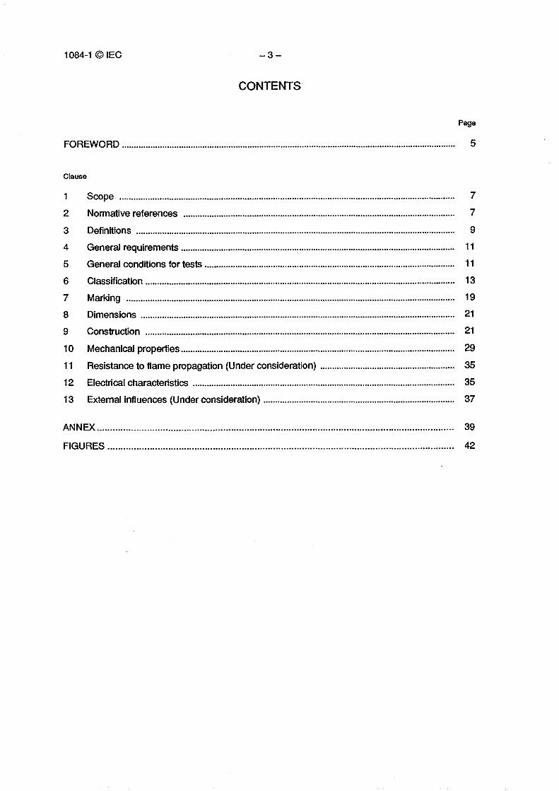
CONTENTS
Page
FOREWORD 5
Clause
1 Scope 72 Normative references 73 Definitions 9
4 General requirements 11
5 General conditions for tests 11
6 Classification 13
7 Marking 19
8 Dimensions 21
9 Construction 21
10 Mechanical properties 2911 Resistance to flame propagation (Under consideration) 35
12 Electrical characteristics 35
13 External influences (Under consideration) 37
ANNEX 39
FIGURES 42
Report on VotingSix Months' Rule
23A(CO)6523A(CO)61
1084-1 © IEC - 5 -
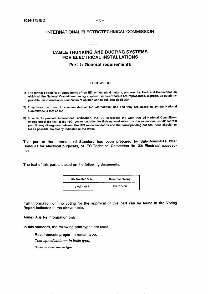
INTERNATIONAL ELECTROTECHNICAL COMMISSION
CABLE TRUNKING AND DUCTING SYSTEMSFOR ELECTRICAL INSTALLATIONS
Part 1: General requirements
FOREWORD
1) The formal decisions or agreements of the IEC on technical matters, prepared by Technical Committees onwhich all the National Committees having a special interest therein are represented, express, as nearly aspossible, an international consensus of opinion on the subjects dealt with.
2) They have the form of recommendations for international use and they are accepted by the NationalCommittees in that sense.
3) In order to promote international unification, the IEC expresses the wish that all National Committeesshould adopt the text of the IEC recommendation for their national rules in so far as national conditions willpermit. Any divergence between the IEC recommendation and the corresponding national rules should, asfar as possible, be clearly indicated in the latter.
This part of the International Standard has been prepared by Sub-Committee 23A:Conduits for electrical purposes, of IEC Technical Committee No. 23: Electrical accesso-ries.
The text of this part is based on the following documents:
Full information on the voting for the approval of this part can be found in the VotingReport indicated in the above table.
Annex A is for information only.
In this standard, the following print types are used:
Requirements proper: in roman type;Test specifications: in italic type;Notes: in small roman type.
1084-1 cOIEC - 7 -
CABLE TRUNKING AND DUCTING SYSTEMSFOR ELECTRICAL INSTALLATIONS
Part 1: General requirements
1 Scope
This standard specifies requirements for cable trunking and cable ducting systems inten-ded for the accommodation, and where necessary for the segregation, of conductors,cables or cords and/or other electrical equipment in electrical installations.
This specification does not apply to conduit, cable tray or cable ladder or current-carryingparts within the system.
NOTE - There are many different designs of systems (see annex A) for which a Part 2 is underconsideration.
2 Normative references
The following standards contain provisions which, through reference in this text, constituteprovisions of this International Standard. At the time of publication, the editions indicatedwere valid. All standards are subject to revision, and pa rties to agreements based on thisInternational Standard are encouraged to investigate the possibility of applying the mostrecent editions of the standards indicated below. Members of IEC and ISO maintainregisters of currently valid International Standards.
IEC 228: 1978, Conductors of insulated cables.
IEC 364: Electrical installations of buildings.
IEC 364-5-51: 1979, Electrical installations of buildings- Pa rt 5: Selection and erection ofelectrical equipment. Chapter 51: Common rules.
IEC 364-5-54: 1980, Electrical installations of buildings- Pa rt 5: Selection and erection ofelectrical equipment. Chapter 54: Earthing arrangements and protective conductors.
IEC 423: 1973, Outside diameters of conduits for electrical installations and threads forconduits and fittings.
IEC 529: 1989, Degrees of protection provided by enclosures (IP Code).

1084-1 ©IEC - 9 -
3 Definitions
For the purpose of this standard, the following definitions apply.
3.1 Cable trunking or ducting system
3.1.1 cable trunking system: A system of closed enclosures comprising a base with aremovable cover intended for the complete surrounding of insulated conductors, cables,cords and/or for the accommodation of other electrical equipment.
3.1.2 cable ducting system: A system of closed enclosures of non-circular section, forinsulated conductors, cables and cords in electrical installations, allowing them to bedrawn in and replaced.
3.2 System components
Parts used within the system which include
a) lengths of trunking or ducting;b) trunking or ducting fittings;c) fixing devices;d) apparatus mounting devices;e) other accessories.NOTE - The above-mentioned components may not necessarily be included all together in a system. Dif-ferent combinations of components may be used.
3.3 trunking length: The main component of a trunking system comprising a base witha removable cover.
3.4 ducting length: The main component of a ducting system, characterized by a closednon-circular cross-section.
3.5 fitting: System component used to connect, change direction or terminate trunkingor ducting lengths.
3.6 fixing device: System device specifically designed to secure other components tothe wall, ceiling or floor.
3.7 apparatus mounting device: System component used to incorporate electricalapparatus (switches, socket-outlets, circuit-breakers, telephone outlets, etc.) added to atrunking or ducting length.
3.8 system accessory: System component used for supplementary functions such ascable separation, cable retention, cable outlets, etc.
3.9 floor service unit: Specific apparatus mounting device used when installing a floorsystem.
1084-1 © IEC – 11 –
3.10 floor access unit: Specific unit used for installing a floor system (inside, flush,external) that provides access to the cables.
3.11 metal component: Component which consists of metal only.
3.12 insulated component: Component which consists of insulating material and has noconductive parts.
3.13 composite component: Component comprising both conductive and insulatingmaterials (plastic and metal or conductive plastic).
3.14 non-flame propagating component: A component which may or may not ignite asa result of an applied flame and does not propagate the flame.
3.15 external influence: The presence of water, oil or building materials, low and hightemperatures, corrosive or polluting substances, solar radiation or mechanical stress.
4 General requirements
Trunking and ducting systems shall be so designed and constructed that where requiredthey ensure reliable mechanical protection to the conductors and/or cables containedtherein. Where required the system shall also provide adequate electrical protection.
Furthermore, the system components shall withstand the stresses likely to occur duringtransport, storage, recommended installation practice and usage.
In general, compliance is checked by carrying out all the tests specified.
5 General conditions for tests
5.1 Tests according to this specification are type tests. Unless otherwise specified, testsare carried out with the trunking or ducting installed as in normal use and the pa rtsassembled according to the manufacturer's instructions.
Type tests on components of a system containing insulating or composite material shallnot commence earlier than 240 h after manufacture. During this period, the samples maybe conditioned in accordance with 10.3.1.
5.2 Unless otherwise specified, the tests are carried out at an ambient temperature of20 °C ± 5 °C.
5.3 Samples of trunking or ducting, hereafter called samples, for various tests are takenfrom different lengths.
1084-1 ©IEC – 13 –
All tests are made on new samples.
Unless otherwise specified, tests are carried out with the cover, if any, in position as innormal use and assembled according to the manufacturer's instructions.
5.4 When toxic or hazardous processes are used, precautions shall be taken to safe-guard the test engineer.
5.5 Unless otherwise specified, the samples are deemed not to comply with the specifi-cation if there are more failures than that of one sample in any one of the tests applicable.If one sample fails in a test, that test and those preceding, which may have influenced theresult of that test, shall be repeated on another set of samples of the number specified, allof which shall then comply with the repeated tests.
NOTE - The applicant, when submitting the first set of samples may also submit the additional set ofsamples, or lengths of trunking/ducting which may be required should one sample fail. The testing stationshall then, without further request, test the additional set of samples, and shall only reject if a furtherfailure occurs. If the additional set of samples is not submitted at the same time, a failure of one sampleshall entail a rejection.
6 Classification
6.1 According to material
6.1.1 Metal trunking/ducting systems.
6.1.2 Insulating material trunking/ducting systems.
6.1.3 Composite material trunking/ducting systems.
6.2 According to mechanical properties
6.2.1 Trunking/ducting systems for very light mechanical stresses.
6.2.2 Trunking/ducting systems for light mechanical stresses.
6.2.3 Trunking/ducting systems for medium mechanical stresses.
6.2.4 Trunking/ducting systems for heavy mechanical stresses.
6.2.5 Trunking/ducting systems for very heavy mechanical stresses.
6.3 According to temperatures
1084-1 © IEC - 15 -
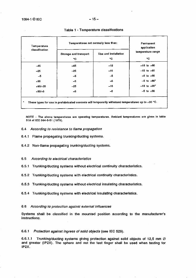
Table 1 - Temperature classifications
Temperatureclassification
Temperatures not normally less than: Permanentapplication
temperature rangeStorage and transport Use and installation
oc °C oc
-45 -45 -15 -15 to +60-25 -25 -15 -15 to +60
-5 -5 -5 -5 to +60+90 -5 -5 -5 to +60°
+90/-25 -25 -15 -15 to +60°+90/-5 -5 -5 -5 to +90
" These types for use in prefabricated concrete will temporarily withstand temperatures up to +90 °C.
NOTE - The above temperatures are operating temperatures. Ambient temperatures are given in table51A of IEC 364-5-51 (1979).
6.4 According to resistance to flame propagation
6.4.1 Flame propagating trunking/ducting systems.
6.4.2 Non-flame propagating trunking/ducting systems.
6.5 According to electrical characteristics
6.5.1 Trunking/ducting systems without electrical continuity characteristics.
6.5.2 Trunking/ducting systems with electrical continuity characteristics.
6.5.3 Trunking/ducting systems without electrical insulating characteristics.
6.5.4 Trunking/ducting systems with electrical insulating characteristics.
6.6 According to protection against external influences
Systems shall be classified in the mounted position according to the manufacturer'sinstructions.
6.6.1 Protection against ingress of solid objects (see IEC 529).
6.6.1.1 Trunking/ducting systems giving protection against solid objects of 12,5 mm 0and greater (IP2X). The sphere and not the test finger shall be used when testing forIP2X.
1084-1 ©IEC - 17 -
6.6.1.2 Trunking/ducting systems giving protection against solid objects of 2,5 mm 0and greater (IP3X).
6.6.1.3 Trunking/ducting systems giving protection against solid objects of 1,0 mm 0 andgreater (IP4X).
6.6.1.4 Trunking/ducting systems giving protection against dust (IP5X).
6.6.1.5 Dust-tight trunking/ducting systems (IP6X).
NOTE - The IP designations above also indicate the degree of protection of persons against access tohazardous pa rts in IEC 529.
6.6.2 Protection against ingress of water (see IEC 529).
6.6.2.1 Trunking/ducting systems giving no protection.
6.6.2.2 Trunking/ducting systems giving protection against vertically falling water drops(IPX1).
6.6.2.3 Trunking/ducting systems giving protection against vertically falling water dropswhen enclosure tilted up to 15° (IPX2).
6.6.2.4 Trunking/ducting systems giving protection against spraying water (IPX3).
6.6.2.5 Trunking/ducting systems giving protection against splashing water (IPX4).
6.6.2.6 Trunking/ducting systems giving protection against water jets (IPX5).
6.6.3 Protection against corrosive or polluting substances.
6.6.3.1 Trunking/ducting systems with low protection outside and inside.
6.6.3.2 Trunking/ducting systems with medium protection outside and low protectioninside.
6.6.3.3 Trunking/ducting systems with medium protection outside and inside.
6.6.3.4 Trunking/ducting systems with high protection outside and low protection inside.
6.6.3.5 Trunking/ducting systems with high protection outside and medium protectioninside.
6.6.3.6 Trunking/ducting systems with high protection outside and inside.
1084-1 ©IEC - 19 -
6.6.4 Protection against solar radiation
6.6.4.1 Trunking/ducting systems without protection.
6.6.4.2 Trunking/ducting systems with low protection.
6.6.4.3 Trunking/ducting systems with medium protection.
6.6.4.4 Trunking/ducting systems with high protection.
6.7 According to cover retention of the system
6.7.1 Access cover removable without tools.
6.7.2 Access cover removable with tools.
7 Marking
7.1 Each length of trunking/ducting and each trunking/ducting fitting shall be marked withthe manufacturer's or responsible vendor's name, trade mark or other identifying symboland the number of this specification.
When trunking/ducting fittings are supplied in a package, a label attached to each packageand marked as above will be sufficient marking.
Flame propagating trunking/ducting systems shall bear a marking indicating clearly thatthey are flame propagating.
7.2 Marking shall be durable and easily legible.
NOTE 1 - Marking may be applied for example by stamping, moulding, printing, labels or water-slidetransfers.
Marking is checked by inspection and by rubbing the marking by hand.
Printed markings or markings applied by transfer shall withstand being rubbed by hand for15 s with a piece of cloth soaked with water and again for 15 s with a piece of clothsoaked with petroleum spirit.
NOTES2 Petroleum spirit is defined as the aliphatic solvent hexane with a maximum aromatics content of 0,1 %volume, a Kauri-butanol value of 29, an initial boiling-point of approximately 65 °C, a d ry-point of approxi-mately 69 °C and a density of approximately 0,68 g/cm3.3 To withstand the rubbing test described in 7.2 suitable protection may be applied to the markings.
1084-1 © IEC -21 -
8 Dimensions
8.1 The manufacturer shall state in mm 2 the internal usable area for cables for thetrunking/ducting.
NOTE - Certain accessories when mounted can reduce the internal usable area for cables.
8.2 Preferred lengths shall be in increments of 0,5 m starting with a minimum of 2 m.
9 Construction
9.1 Any su rface or edge shall not damage the conductors or cables.
Compliance is checked by inspection, if necessary after cutting the samples apart.
9.2 Any screws, studs or other securing devices shall be fitted so as not to damage theconductors or cables.
Slotted cable trunking may have prepared fixing holes. Such holes shall be in accordancewith the relevant Pa rt 2.
Any mounting device providing for the fixing of apparatus shall meet the requirements ofthe appropriate IEC Standard.
Trunking/ducting systems may have means for the segregation of circuits. Such meansshall be adequately secured to the trunking/ducting length.
Compliance is checked by the test of 10.2.
With the exception of small screws and the like, accessible metal pa rts of system compo-nents, which are liable to become live in the event of failure of insulation, shall have thepossibility of being adequately connected to the earthing conductor.
Compliance is checked by the test of 12.2 (Under consideration).
9.3 Fixing screws and small spring clips of insulating trunking fittings need not be of in-sulating material if they do not come into contact with the conductors or cables.
9.3.1 Screws, where used for attaching components or covers if any to trunking compo-nents shall have ISO metric threads or be of the thread forming type; thread cuttingscrews may be used if suitable design provisions are made.

1084-1 ©IEC - 23 -
Fixing screws and small clips for use with insulating components need not be of insulatingmaterial if they are isolated from live pa rts, and are not capable of transmitting a fault cur-rent between equipments connected to the component.
Screw fixing means shall be so designed to withstand the mechanical stresses occurringduring installation and normal use.
Compliance for screw fixing using preformed threads is checked by the test of 9.3.2,followed by inspection.
9.3.2 The screws shall be tightened and removed
- ten times for screws in engagement with a thread of insulating material and forscrews of insulating material;
- five times in all other cases.
The test is made by using a suitable screwdriver or spanner applying a torque accordingto table 2.
Table 2 - Values of torque for screw test
Nominal diameter of thread
mm
TorqueNm
1 2
Up to and including 2,8 0,4 0,4Over 2,8 up to and including 3,0 0,5 0,5Over 3,0 up to and including 3,2 0,6 0,6Over 3,2 up to and including 3,6 0,8 0,8Over 3,6 up to and including 4,1 1,2 1,2Over 4,1 up to and including 4,7 1,8 1,8Over 4,7 up to and including 5,3 2,0 2,0Over 5,3 up to and including 6,0 2,5 3,0Over 6,0 up to and including 8,0 3,5 6,0Over 8,0 up to and including 10,0 4,0 10,0
Column 1 applies to screws which are tightened by means of a screwdriver.Column 2 applies to screws and nuts which are tightened by means other than a screwdriver.
During the test, there shall be no damage such as breakage of the screw or damage tothe head or thread that will impair the further use of the screw. The screws shall not betightened by sudden or jerky motions.
9.4 Access to live parts
9.4.1 Trunking/ducting systems shall be so designed that when they are installed andfitted with insulated conductors and apparatus in normal use, live pa rts are not accessible.
1084-1 ©IEC - 25 -
Compliance is checked by inspection and, if necessary by the tests of 9.4.2, 9.4.3 and 9.4.4on the sample installed as in service and fitted with insulated conductors and accessories.
9.4.2 The standard test finger in accordance with !EC 529 is applied in every possibleposition, an electrical indicator with a voltage not less than 40 V and not more than 50 Vbeing used to show contact with the relevant part.
9.4.3 Insulating and composite components are subject to the following additional test,which is carried out at an ambient temperature of 40 °C ± 2 °C, the sample being at thistemperature.
The sample is subjected for 1 min to a force of 75 N applied through the tip of a straightunjointed test finger of the same dimensions as the standard test finger of IEC 529.
This finger with an electrical indicator as described in 9.4.2 is applied to all places whereyielding of insulating material could impair the safety of the system but is not applied toknock-outs, membranes and the like.
During this test system components with their associated fixing devices shall not deform tosuch an extent that live parts can be touched with the straight unjointed test finger.
9.4.4 Knock-outs are subjected for 1 min to a force of 10 N applied through the tip of astraight unjointed test finger of the same dimensions as the test finger of !EC 529. Duringthis test knock-outs shall not break.
9.5 Inlet openings, if any, shall allow the introduction of the conduit or the protectivecovering of the cable so as to afford complete mechanical protection and shall be so cons-tructed that the conduit or protective covering can enter at least 1 mm into the component.
Inlet openings for conduit entries shall be capable of accepting conduit sizes according toIEC 423.
Compliance is checked by inspection and measurement.
9.6 Membranes
9.6.1 Membranes and the like shall be replaceable and reliably fixed and shall not bedisplaced by the mechanical and thermal stresses occurring in normal use.
Compliance is checked by the test of 9.6.2.
9.6.2 Membranes are tested when assembled in the system. The sample is placed for 2 hin a heating cabinet the temperature being maintained at 40 °C ± 2 °C. Immediately afterthis period a force of 30 N is applied for 5 s to various parts of the membranes by meansof the tip of a straight unjointed test finger of the same dimensions as the test finger ofIEC 529.
1084-1 ©IEC - 27 -
During these tests, the membranes shall not deform to such an extent that live parts be-come accessible and shall not come out. For membranes likely to be subjected to an axialpull in normal use, an axial pull of 30 N is applied for 5 s. During this test, the membranesshall not come out.
9.6.3 Membranes shall be so designed and made of such material that the introduction ofcables into the system is permitted when the ambient temperature is low.
Compliance is checked by the test of 9.6.4.
9.6.4 The system component is fitted with membranes which have not been subjected toany ageing treatment, those without openings being suitably pierced.
The sample is then kept for 2 h in a refrigerator at a temperature as given in column 3 oftable 1.
After this period the sample is removed from the refrigerator, and immediately afterwards,while the sample is still cold, it shall be possible to introduce without undue force, cablesof the heaviest type through the membranes.
After the tests of 9.6.2 and 9.6.4, the membranes shall show no harmful deformation,cracks or similar damage visible to normal or corrected vision without magnification.
9.7 Glands
9.7.1 Screwed glands, if any, shall comply with the test of 9.7.2.
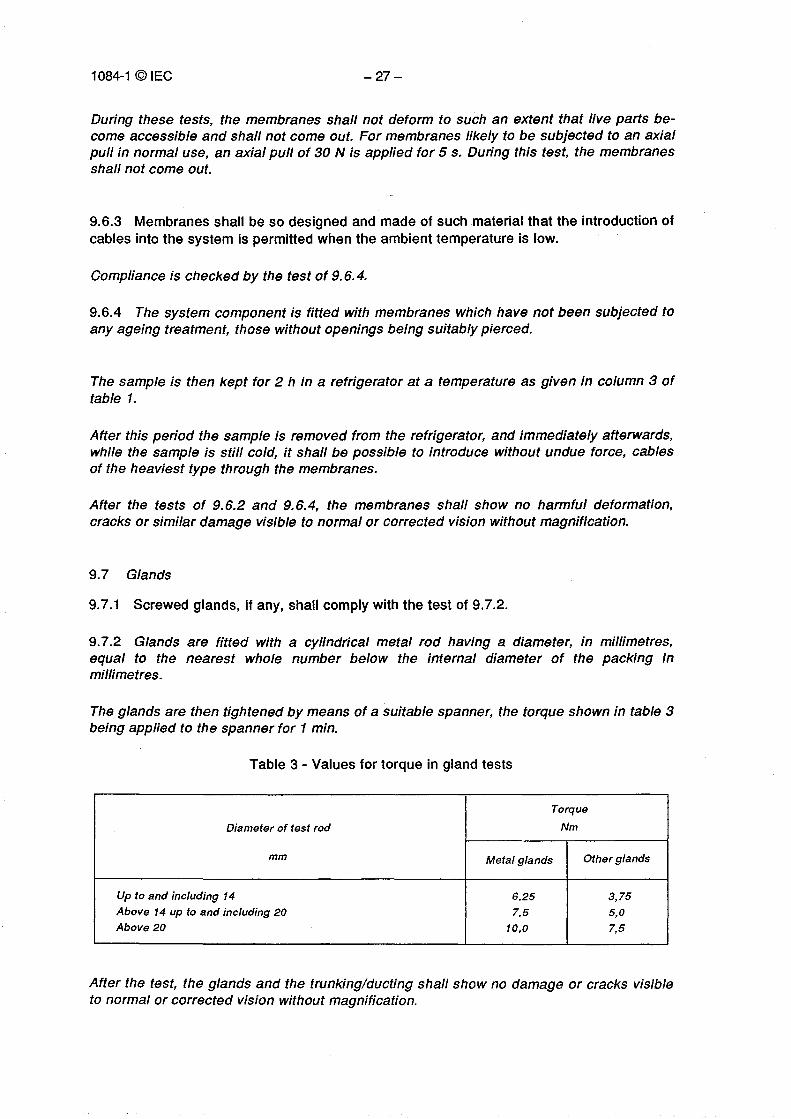
9.7.2 Glands are fitted with a cylindrical metal rod having a diameter, in millimetres,equal to the nearest whole number below the internal diameter of the packing inmillimetres.
The glands are then tightened by means of a suitable spanner, the torque shown in table 3being applied to the spanner for 1 min.
Table 3 - Values for torque in gland tests
Diameter of test rod
mm
Torque
Nm
Metal glands Other glands
Up to and including 14 6,25 3,75Above 14 up to and including 20 7,5 5,0Above 20 10,0 7,5
After the test, the glands and the trunking/ducting shall show no damage or cracks visibleto normal or corrected vision without magnification.
1084-1 ©IEC - 29 -
10 Mechanical properties
10.1 Trunking/ducting systems shall have adequate mechanical strength.
Compliance is checked by the tests specified in 10.2 to 10.6 and by any additional testsspecified in the appropriate Part 2 of this standard.
After all mechanical properties tests the cover, if any, shall not have become detached.
10.2 Cable supporting test for surface mounting
10.2.1 The test is carried out on three samples of main components each having a mini-mum length of 2 m, at a temperature of 20 °C t 5 °C. For insulating and composite maincomponents, three samples each having a minimum length of 250 mm, shall be tested at atemperature of 60 °C ± 2 °C.
Cable retainers, if their use is recommended by the manufacturer, are fitted at centresrecommended by the manufacturer.
10.2.2 Each sample is in turn securely fixed to a rigid suppo rt by means of screws andwashers having a minimum outside diameter of 10 mm according to the manufacturer'sinstructions. For samples whose internal configuration will not accept screws with 10 mmwashers, the screws are suitably adapted.
10.2.3 For the test at 20 °C ± 5 °C, with the samples in position A of figure 1, eachcompartment is subjected to an evenly distributed load of 0,13 kg/cm2 of internal usablecompartment cross-sectional area per metre length.
The load consists of insulated flexible copper cables complying with class 5, table 111 ofIEC 228 (1978). In case the required load cannot be reached, the insulation is removed.
After the load has been applied for 2 h, the distortion is measured. The distortion shall notexceed 10 % of H in figure 1 position A with a maximum of 10 mm. The cover shall not bedetached during the test.
10.2.4 Again at 20 °C ± 5 °C, another set of samples is then placed in position B, andeach compartment subjected to an evenly distributed load of 0,13 kg/cm2 of internalusable compartment cross-sectional area per metre length.
After the load has been applied for 2 h, the distortion is measured. The distortion shall notexceed 10 % of Win figure 1 position B with a maximum of 10 mm. The cover shall not bedetached during the test.
10.2.5 For the test at 60 °C ± 2 °C, with the samples in position A of figure 1, eachcompartment is subjected to an evenly distributed load of 0,13 kg/cm2 of internal usablecompartment cross-sectional area per metre length.
1084-1©IEC - 31 -
After the load has been applied for 2 h, the distortion is measured. The distortion shall notexceed 10 % of H in figure 1 position A with a maximum of 10 mm. The cover shall not bedetached during the test.
10.2.6 Again at 60 °C ± 2 °C, another set of samples is then placed in position B andeach compartment is subjected to an evenly distributed load of 0,13 kg/cm 2 of internalusable compartment cross-sectional area per metre length.
After the load has been applied for 2 h, the distortion is measured. The distortion shall notexceed 10 % of W in figure 1 position B with a maximum of 10 mm. The cover shall not bedetached during the test.
10.3 Impact test
10.3.1 The test is carried out on three samples each 250 mm ± 5 mm long.
Before the test insulating and composite components are conditioned at a temperature of60 °C ± 2 °C for 240 h continuously.
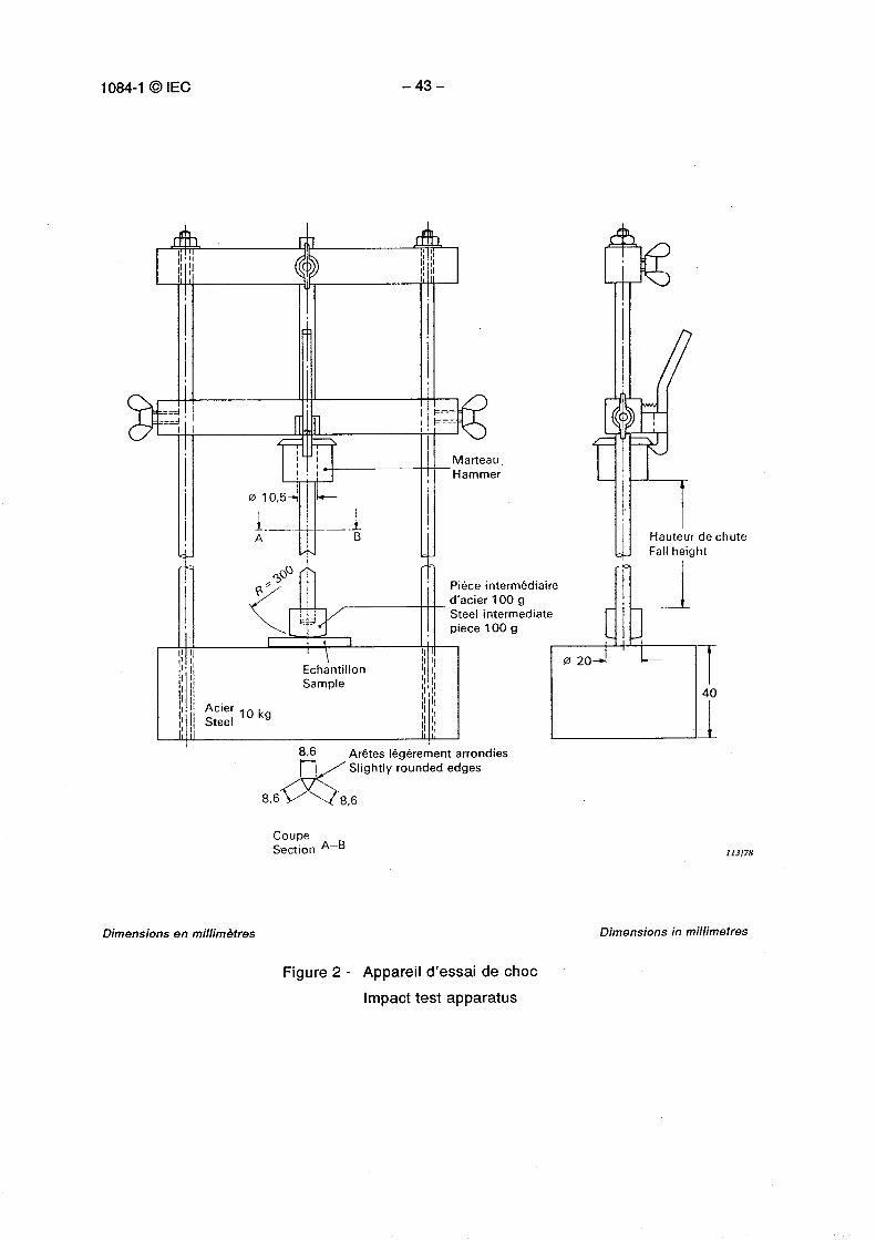
10.3.2 The test apparatus as shown in figure 2, is placed on a pad of closed cell expan-ded EPR sponge, 40 mm thick when uncompressed, and having a density of 450 kg/m 3 to550 kg/m3.
The test apparatus, together with the samples is placed in a refrigerator the temperaturewithin which is maintained at the appropriate temperature specified in column 2 of table 1,within ± 1 °C.
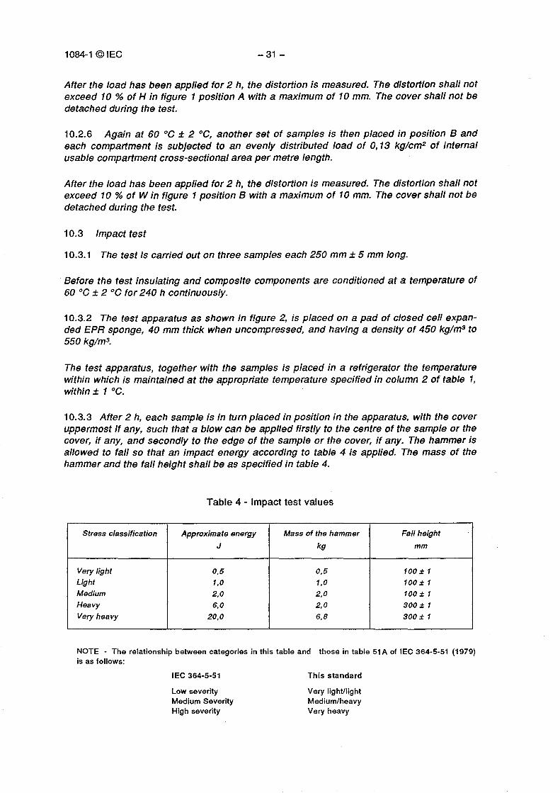
10.3.3 After 2 h, each sample is in turn placed in position in the apparatus, with the coveruppermost if any, such that a blow can be applied firstly to the centre of the sample or thecover, if any, and secondly to the edge of the sample or the cover, if any. The hammer isallowed to fall so that an impact energy according to table 4 is applied. The mass of thehammer and the fall height shall be as specified in table 4.
Table 4 - Impact test values
Stress classification Approximate energyJ
Mass of the hammerkg
Fall heightmm
Very light 0,5 0,5 100 ± 1Light 1,0 1,0 100 t 1Medium 2,0 2,0 100 t 1Heavy 6,0 2,0 300 t 1Very heavy 20,0 6,8 300 t 1
NOTE - The relationship between categories in this table and those in table 51 A of IEC 364-5-51 (1979)is as follows:
IEC 364-5-51 This standardLow severity Very light/lightMedium Severity Medium/heavyHigh severity Very heavy
1084-1 ©IEC - 33 -
10.3.4 After the test the samples shall show no signs of disintegration nor shall there beany cracks visible to normal or corrected vision without magnification. Any cracks ininternal dividers which are not likely to impair electrical safety or use are ignored.
10.4 Linear deflection test
10.4.1 The test is carried out on three samples, which are supported symmetrically at themaximum centre distance recommended by the manufacturer, and the length of the sample isequal to twice the distance between supports. The sample is secured to the supports.
10.4.2 The tests are carried out at a temperature of 20 °C ± 5 °C, and for insulating andcomposite lengths also at a temperature of 60 °C ± 2 °C.
10.4.3 The load is 0,13 kg/cm2 of internal usable compartment cross-sectional area asspecified by the manufacturer per metre length.
10.4.4 The load is applied internally, and evenly distributed over the entire length of thesample, and is produced by using chains weighing 1,16 kg/m and having a link with a ratioof internal length to width of at least 2.
The test is carried out with the cover if any, in each possible position, i.e. mounted at thetop, bottom and either side.
10.4.5 The load is applied for 1 h, and at the end of this period the deflection measuredat the centre of the distance between the suppo rts shall not exceed 1 % of the distancebetween the supports.
The cover, if any, shall not be detached by the applied load.
10.5 External load test (Under consideration)
10.6 Cover retention test
10.6.1 A system component, the cover of which can only be removed by the use of atool, is subjected to the test of 10.6.2. The sample length is 250 mm.
10.6.2 The main part of the system component is firmly fixed to a horizontal support, andthe cover fixed to the main part in accordance with the manufacturer's instructions.
Without the use of a tool, all reasonable effo rt shall be made to remove the covermanually. The cover shall not become detached from the main part.

1084-1 © IEC - 35 -
11 Resistance to flame propagation (Under consideration)
11.1 Non-flame propagating trunking/ducting shall either not ignite or if ignited, shall notcontinue to burn when the source of ignition is removed.
12 Electrical characteristics
12.1 Trunking/ducting systems with electrical continuity characteristics shall be so cons-tructed that they can be used in an installation as a bonding, earthing or protective conduc-tor. Where the system is used as a protective conductor, the requirements of 543.1 of IEC364-5-54 (1980) shall be complied with.
Compliance is checked by the following tests, which are made on three samples of a mini-mum length of 600 mm, each sample consisting of two trunking/ducting lengths connectedtogether according to the manufacturer's instructions.
12.2 Electrical continuity test (Under consideration)
12.3 Electrical insulating strength and insulation resistance test for systems of insulatingand composite materials
Before the test, the samples are tested for the appropriate degree of protection against theingress of water, as claimed by the manufacturer.
Where the samples have partitions or dividers, each compartment is tested as a separatetrunking, the test voltage is also applied to the pa rtitions and dividers.
One end of the sample is closed with a plug of insulating material, which shall allow twoseparate cables to penetrate 25 mm inside the sample, 12 mm of the cables within thesample being without insulation, the ends of the cables being spread so that there is adistance of 12,5 mm between them.
The inside of each compartment of the sample is then filled with spheroidal metal objectsto a maximum size of 2,5 mm, and a bare copper wire is used to interconnect all compart-ments. The remaining end is then closed.
The set of samples is then subjected to humidity treatment, which is carried out in ahumidity cabinet containing air with a relative humidity between 91 % and 95 %, and at atemperature maintained within ± 1 °C of any convenient value t between 20 °C and 30 °C.
Before being placed in the humidity cabinet the samples are brought to a temperaturebetween t and t + 4 °C, this may be achieved by keeping them at this temperature for atleast 4 h before the humidity treatment.
The samples are kept in the cabinet for 48 h.
1084-1 ©IEC - 37 -
A relative humidity between 91 % and 95 % can be obtained by placing in the humiditycabinet a saturated solution of sodium sulphate (Na2SO4) or potassium nitrate (KNO3) inwater having a substantially large contact surface with air.
In order to achieve the specified conditions within the cabinet, it is necessary to ensureconstant circulation of the air within and, in general, to use a cabinet which is thermallyinsulated.
Immediately after the humidity treatment, the samples are coated on the outside with a foilor gauze of good conductivity.
The conductivity of the metal objects within the sample is checked by measuring theresistance between the two cables which have penetrated the sample. The resistancemeasured shall be less than 100 OE
The insulation resistance is measured by applying a d.c. voltage of at least 500 V betweenthe cables and the foil or gauze.
The measurement is made 1 min after the application of the voltage. The insulationresistance shall be not less than 100 MO.
A voltage of 2 500 V of substantially sine-wave form and having a frequency of 50 Hz to60 Hz, from a test apparatus with a characteristic which enables it to supply 200 mA at1 250 V, is then applied between the cables and the foil or gauze, as shown in figure 3.Initially not more than half the voltage is applied and this is raised to 2 500 V as rapidly aspossible without transient overvoltage. It is maintained for 1 min.
No breakdown shall occur during the test.
13 External influences (Under consideration)
1084-1 ©IEC - 39 -
Annex A(informative)
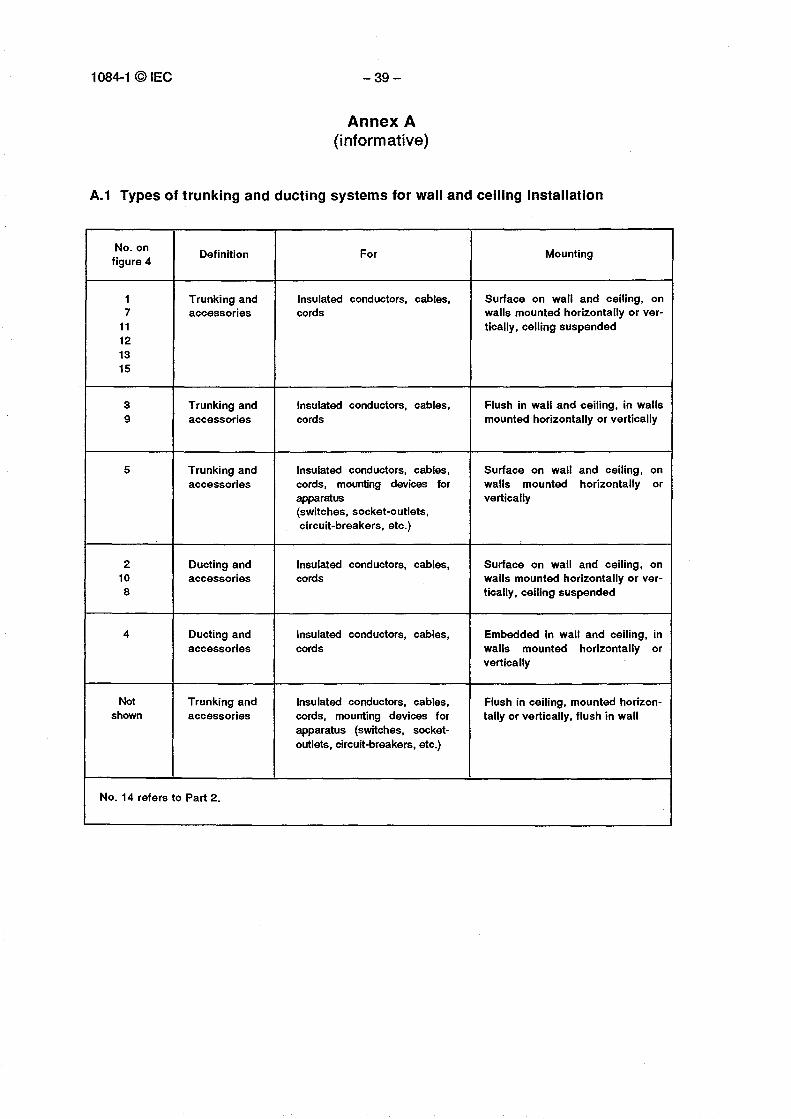
A.1 Types of trunking and ducting systems for wall and ceiling installation
No. onfigure 4
Definition For Mounting
1 Trunking and Insulated conductors, cables, Su rface on wall and ceiling, on7
11accessories cords walls mounted horizontally or ver-
tically, ceiling suspended121315
3 Trunking and Insulated conductors, cables, Flush in wall and ceiling, in walls9 accessories cords mounted horizontally or vertically
5 Trunking andaccessories
Insulated conductors, cables,cords, mounting devices forapparatus
Su rface on wall and ceiling, onwalls mounted horizontally orvertically
(switches, socket-outlets,circuit-breakers, etc.)
2 Ducting and Insulated conductors, cables, Su rface on wall and ceiling, on108
accessories cords walls mounted horizontally or ver-tically, ceiling suspended
4 Ducting andaccessories
Insulated conductors, cables,cords
Embedded in wall and ceiling, inwalls mounted horizontally orvertically
Notshown
Trunking andaccessories
Insulated conductors, cables,cords, mounting devices forapparatus (switches, socket-outlets, circuit-breakers, etc.)
Flush in ceiling, mounted horizon-tally or vertically, flush in wall
No. 14 refers to Part 2.
1084-1 ©IEC -41 -
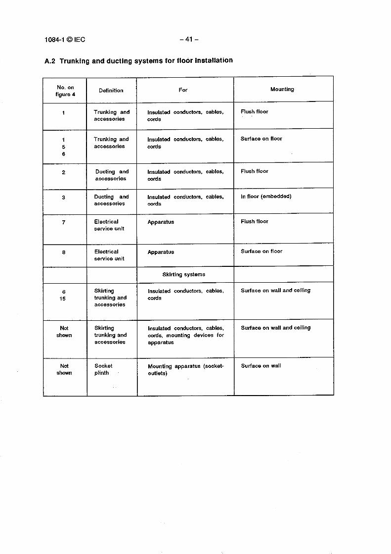
A.2 Trunking and ducting systems for floor installation
No. onfigure 4 Definition For Mounting
1 Trunking andaccessories
Insulated conductors, cables,cords
Flush floor
156
Trunking andaccessories
Insulated conductors, cables,cords
Surface on floor
2 Ducting andaccessories
Insulated conductors, cables,cords
Flush floor
3 Ducting andaccessories
Insulated conductors, cables,cords
In floor (embedded)
7 Electricalservice unit
Apparatus Flush floor
8 Electricalservice unit
Apparatus Surface on floor
Skirting systems
615
Skirtingtrunking andaccessories
Insulated conductors, cables,cords
Surface on wall and ceiling
Notshown
Skirtingtrunking andaccessories
Insulated conductors, cables,cords, mounting devices forapparatus
Surface on wall and ceiling
Notshown
Socketplinth
Mounting apparatus (socket-outlets)
Surface on wall

– 42 – 1084-1 ©CEI
1
Position " A "
DéformationDistortion
CQ-1Et 562/91
Figure 1 - Essai de déformation
Distortion test
I =___ _
__..A i ^— -
Marteau.Hammer
1A
Pièce intermédiaired'acier 100 gSteel intermediatepiece 100 g
EchantillonSample
Acier 10 kgSteel
^n■I ,
1084-1 ©IEC - 43 -
8,6 Arêtes légèrement arrondiesSlightly rounded edges
CoupeSection A—B
Dimensions en millimètres Dimensions in millimetres
Figure 2 - Appareil d'essai de choc
Impact test apparatus
113/78
8,6

Goulotte compartimentéeCompartmented trunking
Points d'essaiTest points
- 44 - 1084-1 © CEI
Feuille ou toile métalliqueFoil or gauze
Ampèremetre à courant continu 10 µA(essai de résistance d'isolement seulement)Meter 10 µA dc(insulation test only)
0
CEI-fEC 563/91
Source d'alimentationPower source
Figure 3 - Appareil d'essai de rigidité diélectrique et de résistance d'isolementElectrical insulating strength and insulation resistance test apparatus
00 00
1084-1 © IEC – 45 –
8 0 6 0v
CEI-IEC 564/91
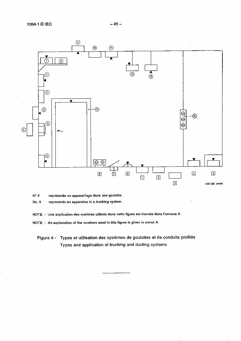
N° 5 représente un appareillage dans une goulotte.
No. 5 represents an apparatus in a trunking system.
NOTE - Une explication des nombres utilisés dans cette figure est donnée dans l'annexe A.
NOTE - An explanation of the numbers used in this figure is given in annex A.
Figure 4 - Types et utilisation des systèmes de goulottes et de conduits profilés
Types and application of trunking and ducting systems
ICS 29.060.01
Typeset and printed by the IEC Central OfficeGENEVA, SWITZERLAND