international e journalsinternationalejournals.com/pdfs/iejmae/iejmae 2.pdf · international e...
TRANSCRIPT
ISSN 0976 – 1411 Available online at www.internationaleJournals.com
International e journals
International eJournal of Mathematics and Engineering 2 (2010) 15-31
IMPROVEMENT OF VARIOUS DISTURBANCES IN POWER SYSTEM
USING DYNAMIC VOLTAGE RESTORER
Nitin Aggarwal1, K.Rajendra2, Arvind Dewangan3, Prakash Kumar Dewangan4
1 Department of Electrical & Electronics Engg., Haryana college of Technology & Management, Kaithal[Haryana],India. Email:[email protected] 2 Department. of Electrical & Electronics Engg., Haryana college of Technology & Management, Kaithal[Haryana], India. 3 Department. of Civil Engg., Haryana college Of Technology & Management, Kaithal[Haryana],India. 4 Department. of Electrical Engg., Kirodimal Institute of Technology, Raigarh[Chattisgarh], India.
Abstract
A Power quality problem is an occurrence manifested as a nonstandard voltage, current or frequency that results in a failure or a mis-operation of end user equipments. Utility distribution networks, sensitive industrial loads and critical commercial operations suffer from various types of outages and service interruptions which can cost significant financial losses. These power quality associated problems are voltage sag, surge, flicker, voltage imbalance, interruptions and harmonic problems. These power quality issues may cause problems to the industries ranging from malfunctioning of equipments to complete plant shut downs. Those power quality problems affect the microprocessor based loads, process equipments, sensitive electric components which are highly sensitive to voltage level fluctuations. In developing countries like India, where the variation of power frequency and many such other determinants of power quality are themselves a serious question, it is very vital to take positive steps in this direction. To overcome the problems caused by customer side abnormalities so called custom power devices are connected closer to the load end.
One such reliable customer power device used to address the voltage sag, swell problem is the Dynamic Voltage Restorer (DVR). It is a series connected custom power device, which is considered to be a cost effective alternative when compared with other commercially available voltage sag compensation devices.
The main function of the DVR is to monitor the load voltage waveform constantly and if any sag or surge occurs, the balance (or excess) voltage is injected to (or absorbed
16
Nitin Aggarwal, K.Rajendra, Arvind Dewangan, Prakash Kumar Dewangan | International eJournal of Mathematics and Engineering 2 (2010) 15-31
from) the load voltage. To achieve the above functionality a reference voltage waveform has to be created which is similar in magnitude and phase angle to that of the supply voltage.
This paper reveal a new control technique to detect and compensate for the single phase voltage sag. The simulation was checked in MATLAB Simulink/Power System Block set (PSB) simulation software and has shown reliable results.
Keywords: DVR, voltage dips, swells, outage, interruption, power quality, VSC. Sub Area: Power System [ DVR]
Area: Electrical Engineering.
1. INTRODUCTION The technological advancements have proven a path to the modern industries to
extract and develop the innovative technologies within the limits of their industries for the fulfillment of their industrial goals. And their ultimate objective is to optimize the production while minimizing the production cost and thereby achieving maximized profits while ensuring continuous production throughout the period.
As such a stable supply of un-interruptible power has to be guaranteed during the
production process. The reason for demanding high quality power is basically the modern manufacturing and process equipment, which operates at high efficiency, requires high quality defect free power supply for the successful operation of their machines. More precisely most of those machine components are designed to be very sensitive for the power supply variations. Adjustable speed drives, automation devices, power electronic components are examples for such equipments.
The concern for the quality of electric power is increasing very rapidly due to
advances in power system components. For decades research and has been concentrated on the first aim. Quality of supply was rarely an issue. A change in attitude came about probably in the early 1980s. This change has meant that sensitivity of equipment to disturbances has increased and therefore the reliability of power is of much concern. Starting in industrial and commercial power systems and spreading to the public supply, the Power quality problems appeared. Therefore to increase or maintain the reliability of a system constant monitoring of the quality of power is required.
Sensitive equipment and non-linear loads are now more common place in both the
Industrial, commercial sectors and the domestic environment. Because of this a high awareness of power quality is developing amongst electricity users. An enormous amount of research papers are written concerning the monitoring and analysis of power quality in power systems. It is an umbrella concept for a multitude of individual types of power system disturbances. Some of the most common PQ disturbances include interruptions; voltage sags and swells; harmonic distortions and surges. These are depicted in Fig 1.1[1]

17
Nitin Aggarwal, K.Rajendra, Arvind Dewangan, Prakash Kumar Dewangan | International eJournal of Mathematics and Engineering 2 (2010) 15-31
Fig. 1.1 Common Power Quality Disturbances
2. POWER QUALITY Power quality is the concept of powering and grounding sensitive equipment in a
matter that is suitable to the operation of that equipment. Power quality is the study or description of both voltage and current disturbances. Power quality can be seen as the combination of voltage quality and current quality.
2.1 POWER QUALITY PROBLEMS Power quality problems are caused by a wide range of phenomena. Many of these are
natural causes, such as lightning. Other sources of power quality disturbance, for example the operation of power system equipment may be found in industry, or within the power system itself, where faults may cause voltage sag at the consumer end.
Power quality disturbance covers sudden, short duration deviation impulsive and
oscillatory transients, voltage dips (or sags), short interruptions, as well as steady- state deviations, such as harmonics and flicker.
VOLTAGE POWER QUALITY PROBLEMS
Voltage Sag Voltage Swell Voltage Interruption Under/ Over Voltage Voltage Flicker Harmonic Distortion Voltage Notching Transient Disturbance Outage and frequency variation

18
Nitin Aggarwal, K.Rajendra, Arvind Dewangan, Prakash Kumar Dewangan | International eJournal of Mathematics and Engineering 2 (2010) 15-31
Table 2.1 Categories of Various Power Quality Variations[10]
2.2 CAUSES OF POWER QUALITY VARIATIONS
The main causes of Poor power quality come from the customers (Internal), generated from one customer that may impact other customers and also from the utility. The types and causes of power quality variations are as follows:
Types Causes
Transient Small lightning strikes at low voltage levels (e.g.500V) can disrupt or Transient damage electronic equipment.. Poor connections in the wiring system lead to arcing caused transients. Switching of power electronics devices
Long Duration Voltage Variations
Over- and under-voltages are caused by load variations on the system. Overloaded circuits results in under voltages. Sustained interruptions variations are caused by lightning strikes.
Short Duration Voltage Variations
Sags and swells occurs whenever there is a sudden change in the load current or voltage. Sags result when a load turns on suddenly (e.g. starting of large motors).
Waveforms Distortions
Current distortion affects the power system and distribution equipment. Overheating and failure in transformer and high neutral currents are some direct problems. Nonlinear loads (eg. Variable frequency drives, induction motors, and power

19Nitin Aggarwal, K.Rajendra, Arvind Dewangan, Prakash Kumar Dewangan | International eJournal of Mathematics and
Engineering 2 (2010) 15-31 electronics components) cause voltage distortions, which can cause motor to overheat and vibrate excessively, resulting in damage to the shaft of motors.
Wiring& grounding
Inappropriate or Poor wiring and grounding can affect the operation and reliability of sensitive loads and local area networks.
Table2.2 Internal Causes of Power Quality Variations [2]
Types Causes and Effects Transient Transients are generated from the switching of loads. In
situations Where multiple, separate businesses share wiring or other parts of the Power system, arcing-based transients are possible. Reactive loads, regardless of light or heavy motors, generate spikes.
Long/Short Duration Voltage Variations
Changing currents interact with the system impedance. Loads in the neighbor's facility must be large and changing enough to affect the voltage feeding the customer's facility or office. Overloading may be the cause as well.
Waveforms Distortions
If a customer's neighbors draw large amount of distorted current, this current will subsequently distort the utility supply voltage, which is then fed back to the customer. Hence, loads within the customer's business are subjected to potential problems.
Table 2.3 Neighboring Causes of Power Quality Variations[2]
Types Causes Transient The most common causes of transients come from lightning
surges. Other causes include capacitor bank energization, transformer energization, system faults.
Long Duration Voltage Variations
These voltage variations are the result of load switching (eg. Switching on/off a large load, or on/off a capacitor bank). Incorrect tap settings on transformers can also cause system over voltages.
Short Duration Voltage Variations
These variations are caused by fault conditions, energization of large loads that require high starting currents, or intermittent loose connections in power wiring. Delayed reclosing of protective devices may cause momentary or temporary interruptions
Voltage and Current Imbalance
Primary source of voltage unbalance is unbalanced load (thus current unbalance). This is due to an uneven spread of single-phase, low voltage customers over the three phases, but more commonly due to a large single-phase load. Three-phase unbalance can also result because of capacitor bank anomalies, such as a blown fuse in one phase of a three-phase bank.
Poor Frequency Variation
The frequency of the supply voltage is not constant. This frequency variation is due to unbalance between load and generation. Short circuits also contribute to this variation

20
Nitin Aggarwal, K.Rajendra, Arvind Dewangan, Prakash Kumar Dewangan | International eJournal of Mathematics and Engineering 2 (2010) 15-31
Waveforms Distortions
The amount of harmonic distortion originating from the power system is normally small. The increasing use of power electronics for control of power flow and voltage (flexible ac transmission systems or FACTS) carries the risk of increasing the amount of harmonic distortion originating in the power system. Inter harmonics can excite unexpected resonance between transformer inductances and capacitor banks. More dangerous are sub-harmonic currents, which can lead to saturation of transformers and damage to synchronous generators and turbines.
Table 2.4 Utility Causes of Power Quality Variations[3]
3. DYNAMIC VOLTAGE RESTORER
3.1 PRINCIPLE
Voltage sags and outages can cause significant disruptions to modem industrial processes and hence has generated a greater awareness to mitigate the effect of such voltage disturbances. A device consists of a voltage sourced inverter and a dc-link storage called dynamic voltage restorer (DVR) has been developed to solve this problem. This provides simultaneous power control and Power quality functions. The DVR is best suited to protecting sensitive loads from incoming supply disturbances such as voltage dips. Dynamic voltage restorer (DVR) is a power-electronic converter based device that has been designed to protect critical loads from all supply-side disturbances other than outages.
Fig. 3.1Schematic representation of the DVR
It is connected in series with a distribution feeder and is capable of generating or absorbing real and reactive power at its ac terminals. The basic principle of a DVR is simple: by inserting a voltage of required magnitude and frequency, the DVR can restore the load-side voltage to the desired amplitude and waveform even when the source voltage is unbalanced or distorted. Usually a DVR is connected to protect sensitive loads during faults in the supply system[3].
The first DVR was installed in North Carolina, for the rug manufacturing industry. Another was installed to provide service to a large dairy food processing plant in Australia. A DVR is usually built round a dc–ac power converter that is connected in series with a distribution line through three single phase transformers. The dc side of the converter is connected to a dc energy-storage device. The energy
state of the device is regulated by taking power from the feeder[4].

21
Nitin Aggarwal, K.Rajendra, Arvind Dewangan, Prakash Kumar Dewangan | International eJournal of Mathematics and Engineering 2 (2010) 15-31
Fig. 3.2 The DVR Configuration
As the PWM modulation scheme is used to synthesize the injected voltage, the switching frequency harmonics must be prevented from entering into the utility and customer system. A low-pass filter must be introduced to accomplish this function. However, it will cause an additional voltage drop when the load current flows through the filter. This consideration is very important in large capacity DVR.
3.2 STRUCTURE OF DVR
The DVR basically consists of a power circuit and a control circuit. Control circuit is used to derive the parameters (magnitude, frequency, phase shift, etc.) of the control signal that has to be injected by the DVR. Based on the control signal, the injected voltage is generated by the switches in the power circuit. Further power circuit describes the basic structure of the DVR. Power circuit mainly comprising of five units as in Figure 3.3 [4]
Fig. 3.3 DVR Power circuit
3.3 DVR SERIES INTERCONNECTION The DVR is connected to the utility primary distribution feeder in series. The series
interconnection as shown in Fig. 3.4 is required to allow the inserted voltage waveform to add to the utility system voltage. The sum of the line voltage and the insertion voltage becomes the restored voltage seen by the critical load. Because it is series connected, the DVR will see the full load current as well as any fault currents due to downstream faults. The rating of the DVR inverters becomes the limiting factor for normal load current seen in the primary windings and reflected in the secondary windings of the series insertion transformer[3].

22
Nitin Aggarwal, K.Rajendra, Arvind Dewangan, Prakash Kumar Dewangan | International eJournal of Mathematics and Engineering 2 (2010) 15-31
Fig.3.4Series connected DVR supplies ‘missing’ Voltage waveforms during sags[3]
3.4 VOLTAGE SOURCE INVERTER Generally Pulse-Width Modulated Voltage Source Inverter (PWMVSI) is used. The
basic function of the VSI is to convert the DC voltage supplied by the energy storage device into an AC voltage. In the DVR power circuit step up voltage injection transformer is used. Thus a VSI with a low voltage rating is sufficient. The common inverter connection methods for three phase DVRs are 3 phase Graetz bridge inverter, Neutral Point Clamp inverter and H Bridge inverter for single phase DVRs.
3.5 VOLTAGE INJECTION TRANSFORMERS The high voltage side of the injection transformer is connected in series to the
distribution line, while the low voltage side is connected to the DVR power circuit. For a three-phase DVR, three single-phase or three-phase voltage injection transformers can be connected to the distribution line, and for single phase DVR one single-phase transformer is connected [5]. For the three-phase DVR the three single phase transformers can be connected either in delta/open or star/open configuration as shown in Figure 3.6
Fig 3.6: Connection methods for the primary side of the injection transformer Left : delta/open configuration Right : Star/open configuration[5]
The basic function of the injection transformer is to increase the voltage supplied by the filtered VSI output to the desired level while isolating the DVR circuit from the distribution network. A higher transformer winding ratio will increase the primary side

23
Nitin Aggarwal, K.Rajendra, Arvind Dewangan, Prakash Kumar Dewangan | International eJournal of Mathematics and Engineering 2 (2010) 15-31
current, which will adversely affect the performance of the power electronic devices connected in the VSI. In order to reduce the saturation of the injection transformer under normal operating conditions it is designed to handle a flux which is higher than the normal maximum flux requirement [5].
The winding configuration of the injection transformer mainly depends on the
upstream distribution transformer. During an unbalance fault or an earth fault in the high voltage side, there will not be any zero sequence currents flow in to the secondary. Thus the DVR needs to compensate only the positive and negative sequence components. As such, an injection transformer which allows only positive and negative sequence components is adequate [6]. Consequently the delta/open configuration can be used (shown in Figure 3.6-left). For any other winding configurations (such as star/star earthed) of the distribution transformer, during an unbalance fault all three sequence components (positive, negative and zero) flow to the secondary side. Therefore the star/open configuration (Figure 3.6-right) should be used for the injection transformers, which can pass all the sequence components.
3.6 VOLTAGE SAG CORRECTION BY DVR
Voltage magnitude is one of the major factors that determine the quality of power supply. Loads at distribution level are usually subject to frequent voltage sags due to various reasons. Voltage sags are highly undesirable for some sensitive loads, especially in high-tech industries. It is a challenging task to correct the voltage sag so that the desired load voltage magnitude can be maintained during the voltage disturbances.
Dynamic voltage restorer (DVR) can be used to correct the voltage sag at distribution
level. A DVR is a series device that generates an ac voltage and injects it in series with the supply voltage through an injection transformer to compensate the voltage sag. For lower voltage sags, the load voltage magnitude can be corrected by injecting only reactive power into the system. However, for higher voltage sags, injection of active power, in addition to reactive power, is essential to correct the voltage magnitude. The expected response time is about 25 ms, and which is much less than some of the traditional methods of voltage correction such as tap changing transformers. [7].
The VSC switching strategy is based on a sinusoidal PWM technique, which offers
simplicity and good response. Since custom power is a relatively low-power application, PWM methods offer a more flexible option than the fundamental frequency switching (FFS) methods favored in FACTS applications. Besides, high switching frequencies can be used to improve on the efficiency of the converter, without incurring significant switching losses.
In order to control the semiconductors of the PWM Inverter, a triangular reference
signal along with a sinusoidal reference signal are used to determine the switching times for the semiconductors. These inputs are compared and will control the ON/OFF states of the semiconductors.
4. SIMULATION OF DVR 4.1 DYNAMIC VOLTAGE RESTORER (DVR) The DVR configuration consists of a VSC, a dc energy storage device and a coupling transformer connected in series with the ac system, and associated control circuits. The VSC converts the dc voltage across the storage device into a set of three-phase ac output voltages. These voltages are in phase and coupled with the ac system through the series coupling

24
Nitin Aggarwal, K.Rajendra, Arvind Dewangan, Prakash Kumar Dewangan | International eJournal of Mathematics and Engineering 2 (2010) 15-31
The sinusoidal signal Vcontrol
is phase-modulated by means of the angle δ
transformer. Suitable adjustment of the phase and magnitude of the DVR output voltages allows effective control of voltage restoration of distribution system. The design approach of the control, system determines the priorities and functions developed in each case.The DVR is used to regulate voltage at the point of connection. The direct control is based on sinusoidal PWM and it requires the measurement of the rms voltage and current at the load point. 4.2 CONTROLLER FOR DVR
The aim of the control scheme is to maintain constant voltage magnitude at the point where a sensitive load is connected, under system disturbances. The control system only measures the r.m.s voltage at the load point, i.e., no reactive power measurements are required. The VSC switching strategy is based on a sinusoidal PWM technique which offers simplicity and good response.
The controller input is an error signal obtained from the reference voltage and the
value rms of the terminal voltage measured. Such error is processed by a PI controller the output is the angle δ, which is provided to the PWM signal generator. It is important to note that in this case, indirectly controlled converter, there is active and reactive power exchange with the network simultaneously: an error signal is obtained by comparing the reference voltage with the rms voltage measured at the load point.
Fig. 4.1 Indirect PI controller
The modulated signal Vcontrol
is compared against a triangular signal in order to generate the switching signals for the VSC valves. The main parameters of the sinusoidal PWM scheme are the amplitude modulation index of signal, and the frequency modulation index of the triangular signal which will used to generate Three Phase waveforms.
0.475 0.48 0.485 0.49 0.495 0.5-1
-0.8
-0.6
-0.4
-0.2
0
0.2
0.4
0.6
0.8
1
Time(sec)
Voltage
Fig. 4.2 Three Phase Waveforms generated by DVR Controller

25Nitin Aggarwal, K.Rajendra, Arvind Dewangan, Prakash Kumar Dewangan | International eJournal of Mathematics and Engineering 2 (2010) 15-31
0 0.1 0.2 0.3 0.4 0.5 0.6 0.7 0.8 0.9 1-0.5
0
0.5
1
1.5
time(sec)
voltage(pu)
The modulating angle is applied to the PWM generators in phase A. The angles for phases B and C are shifted by 2400 and 1200, respectively. It can be seen in that the control implementation is kept very simple by using only voltage measurements as the feedback variable in the control scheme. The speed of response and robustness of the control scheme are clearly shown in the simulation results and pulses by Discrete PWM generator are shown in Fig. 4.3
Fig.4.3 Pulses Generated by PWM Generator
4.3 TEST SYSTEM FOR DVR
The test system employed to carry out the simulations concerning the DVR actuation is shown in Fig. 4.4. Such network is composed by a 13 kV, 50 Hz generation system, represented by a Thevenin equivalent, feeding two transmission lines through an 3-winding transformer connected in Y/∆/∆ 13/115/115 kV. Such transmission lines feed two distribution networks through two transformers connected in ∆/Y, 115/11 kV. To verify the working of a DVR employed to avoid voltage sags during short -circuit, a fault is applied at point X via a resistance of 0.4 Ω. Such fault is applied from 500 to 900 ms.
Fig. 4.4 Test System for DVR
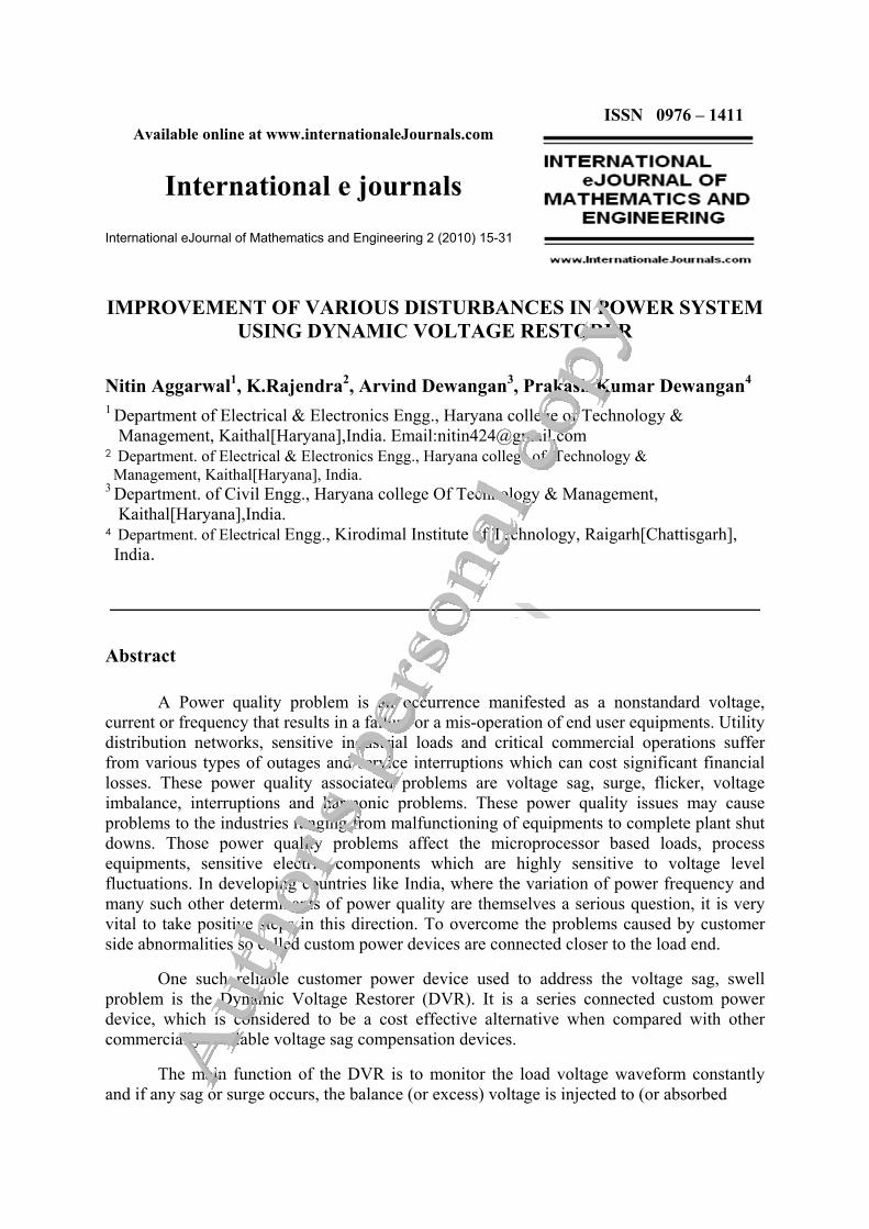
The above test system is simulated under the environment of MATLAB/SIMULINK and Power System Block set (PSB) the model used for this purpose is shown in the Fig.4.5
26
Discrete,Ts = 1e-005 s.
datav in
controller
g
A
B
C
+
-
Univ Bridge
z
1
Unit Delay
AB
CThree-Phase Source
A
B
C
A
B
C
Three-Phase FaultVabc A
B
C
a
b
c
Three-PhaseV-I Measurement
Vabc
A B C
a b c Three-PhaseV-I Meast
A
B
C
a
b
c
Three-PhaseTransformer
(Two Windings)1
A
B
C
a
b
c
Three-PhaseTransformer
(Two Windings)
A
B
C
a2
b2
c2a3
b3
c3
Three-PhaseTransformer
(Three Windings)
ABC
ABC
Three-PhaseSeries RLC Branch3
ABC
ABC
Three-PhaseSeries RLC Branch2
A
B
C
A
B
C
Three-PhaseSeries RLC Branch1
A
B
C
A
B
C
Three-PhaseSeries RLC Branch
Te1
Te
1
2
TF2
Scope1
S
Signal(s)Pulses
PWM1
PWM
A B CPF CorrectionCapacitor
75 kvar
1
2
Linear Transformer2
D
1 Constant
AB
C
ab
c
BUS1
B3
B2
B1
3-phase
abc
Mag
Phase
3-P1
abc
Mag
Phase
3-P
1
2
TF1
PI
Nitin Aggarwal, K.Rajendra, Arvind Dewangan, Prakash Kumar Dewangan | International eJournal of Mathematics and Engineering 2 (2010) 15-31
Fig. 4.5 Simulation Model of DVR
4.4 SIMULATION MODEL OF TEST SYSTEM FOR VOLTAGE SAGs Following simulations studies are carried out as follows:
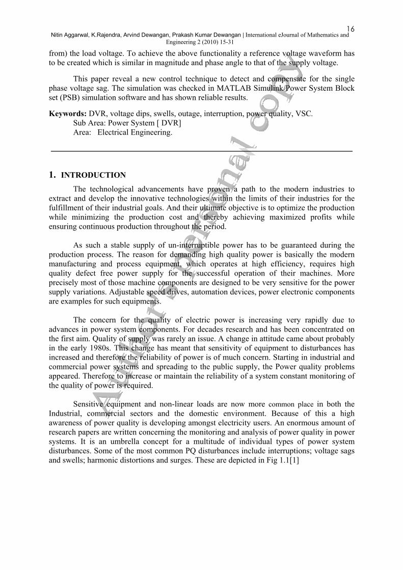
1) The first simulation is done without using DVR and a three phase short-circuit fault is applied at a fault resistance of 0.4Ω. The voltage sag at the load point is almost 60% with respect to the reference voltage which is shown in Fig. 4.6
Fig. 4.6 Voltage at Load point without DVR
Simulation results with the presence of 3-Φ fault without DVR are shown in Fig. 4.7(a),(b),(c)

27
Nitin Aggarwal, K.Rajendra, Arvind Dewangan, Prakash Kumar Dewangan | International eJournal of Mathematics and Engineering 2 (2010) 15-31
0 2 4 6 8 10 12
x 104
-60
-50
-40
-30
-20
-10
0
10
20
30
40
Time(Sec)
Voltage(pu)
Fig.4.7(a)
0 0.1 0.2 0.3 0.4 0.5 0.6 0.7 0.8 0.9 1-80
-60
-40
-20
0
20
40
time(sec)
voltage(pu)
Fig. 4.7(b)
0 0.1 0.2 0.3 0.4 0.5 0.6 0.7 0.8 0.9 1-40
-20
0
20
40
60
80
100
time(sec)
volatge(pu)
Fig. 4.7(c)
Fig 4.7 Various Voltage Waveforms Between Phases
In case of healthy system, without occurrence of any fault our result will become without any Voltage Interruption, Voltage sag and Voltage swell. This is shown in Fig 4.8.
0 0.5 1 1.5 2 2.5
x 105
-8
-6
-4
-2
0
2
4
6
8
Voltage(p.u.)
Time(sec) Fig. 4.8 Voltage waveform without Interruption, Sag and Swell

28
Nitin Aggarwal, K.Rajendra, Arvind Dewangan, Prakash Kumar Dewangan | International eJournal of Mathematics and Engineering 2 (2010) 15-31
2) Simulation is carried out using the DVR for 3-Φ fault. The total simulation period is
1.4 s. using the facilities available in MATLAB. The DVR is simulated in operation only for the duration of the fault. When the DVR is in operation the voltage sag is mitigated almost completely and the rms voltage is maintained at 98% as shown in Fig. 4.9
Fig. 4.9 Voltage response of Test System with DVR
The PWM control signal is generated as shown in Fig.4.10 controls the magnitude and the phase of the injected voltages, restoring the rms voltage very effectively. The sag mitigation is performed with a smooth, stable, and rapid DVR response.
0 0.1 0.2 0.3 0.4 0.5 0.6 0.7 0.8 0.9 1-0.5
0
0.5
1
1.5
time(sec)
voltage(pu)
Fig. 4.10 Pulses generated by PWM generator
Here in this analysis of results, we can also find out the current between phase which is shown in Fig.4.11 and between phase and ground is shown in Fig. 4.12
0 2 4 6 8 10 12
x 104
-15
-10
-5
0
5
10
15
Fig. 4.11 Current at Load side
29
Nitin Aggarwal, K.Rajendra, Arvind Dewangan, Prakash Kumar Dewangan | International eJournal of Mathematics and Engineering 2 (2010) 15-31
0 2 4 6 8 10 12
x 104
-4000
-3000
-2000
-1000
0
1000
2000
3000
4000
5000
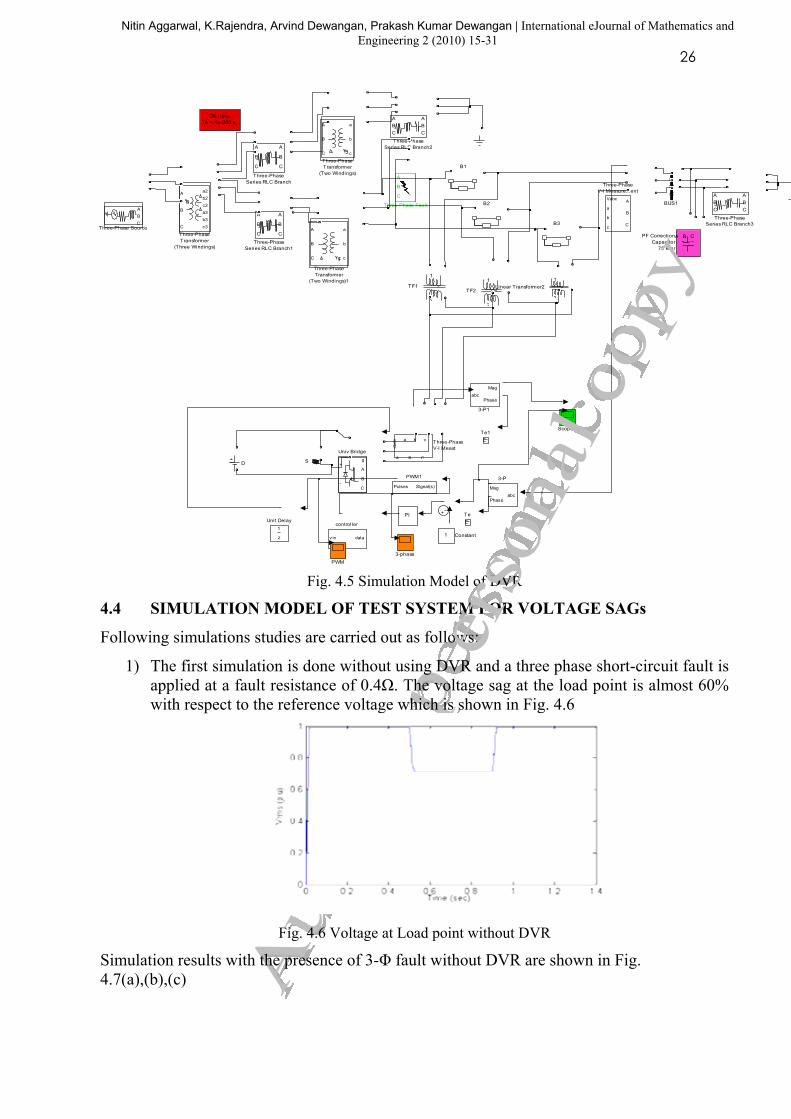
Fig.4.12 Current between phase and ground
3) The simulation results without DVR with capacitive load which is of very high value in the range of 20µF. The voltage swell at the load point is 25%is shown in Fig. 4.13
Fig4.13 Voltage at Load end for Capacitive Load without DVR
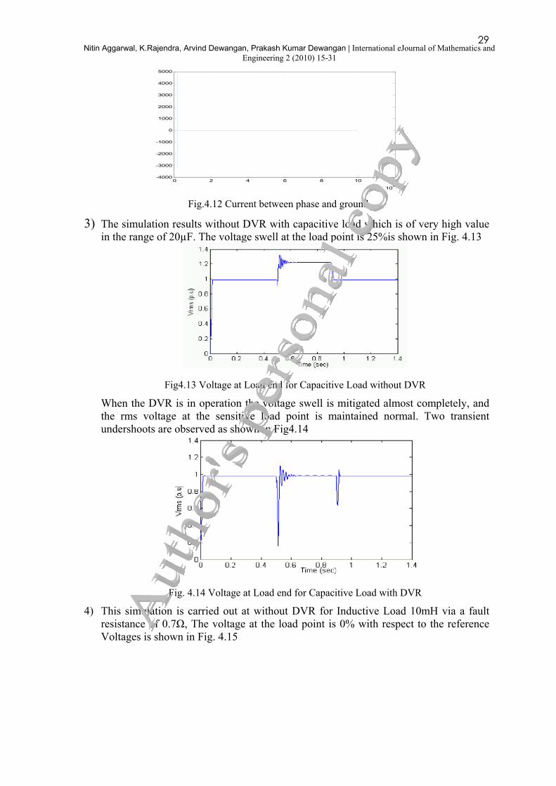
When the DVR is in operation the voltage swell is mitigated almost completely, and the rms voltage at the sensitive load point is maintained normal. Two transient undershoots are observed as shown in Fig4.14
Fig. 4.14 Voltage at Load end for Capacitive Load with DVR
4) This simulation is carried out at without DVR for Inductive Load 10mH via a fault resistance of 0.7Ω, The voltage at the load point is 0% with respect to the reference Voltages is shown in Fig. 4.15

30Nitin Aggarwal, K.Rajendra, Arvind Dewangan, Prakash Kumar Dewangan | International eJournal of Mathematics and
Engineering 2 (2010) 15-31
0 2 4 6 8 10 12
x 104
-80
-60
-40
-20
0
20
40
Time(sec)
Voltage(p.u.)
Fig. 4.15 Voltage at Load end for Inductive load without DVR
Simulation is carried out using the same scenario as above but now with the DVR in operation. When the DVR is in operation the voltage sag is mitigated almost completely, and the rms voltage at the sensitive load point is maintained at 98%, is shown in Fig.4.16
0 0.1 0.2 0.3 0.4 0.5 0.6 0.7 0.8 0.9 1-10
-8
-6
-4
-2
0
2
4
6
8
10
time(sec)
current(pu)
Fig. 4.16 Voltage at Load end for Inductive Load
5. CONCLUSIONS
Voltage sags and surges are a common problem faced by the electricity consumers. As many industries have already making their product from the raw materials, solution to this electricity problem has been identified as the potential issue to reduce their production cost. Its sources and its effects are explained in detail. Among those custom power devices are the new trend of devices to solve more power quality problems such as sags swells and harmonics. The main reason of that is a DVR corrects the Voltage Sag only on the downstream side. The commonest solution for the above problem is moving into a full UPS system, which is a costly alternative.
The designed control system was implemented using the MATLAB/PSB (Power
System Block Set) software and It is simulated using Sim Power Systems. The system was simulated for several cases. To cover all possible voltage sags, the sags were created, and it was initiated different point of the supply voltage waveform. Finally the supply voltage with harmonic content also checked in the simulation.
A new direct control is used for simulations. Results obtained were compared with results
obtained in index journals. A new PWM-based control scheme has been implemented to control the electronic valves in voltage source converter.
In this present work , a study about the behavior of custom power device DVR to improve
the voltage stability of distribution networks with overloading and faults has been done.

31
Nitin Aggarwal, K.Rajendra, Arvind Dewangan, Prakash Kumar Dewangan | International eJournal of Mathematics and Engineering 2 (2010) 15-31
Simulation results showed that DVR can increase the voltage stability limit and provide relatively better Voltage regulation capabilities. It was also observed that the capacity of power compensation and Voltage regulation of DVR depends on the rating of dc storage device.
REFERENCES [1] K.Chan, A.Kara, P.Dachler, J.Guay, R.Tinggren,”Innovative system Solutions for
Power Quality Enhancement”, IEEE Transcation on power Delivery.
[2] A. Moreno-Muno (Ed.),” Power Quality-Mitigation Technologies in Distribution Environment”, Springer, Verlog London Limited 2007.
[3] N.H. Woodley, L.Morgan and A.Sundram,” Experience with an inverter–based dynamic voltage restorer”, IEEE Trans. Power Delivery, Vol.14, No.3, pp.1181-1186, 1999.
[4] F. Z. Peng, H. Akagi, and A. Nabae, "Compensation characteristics of the, combined system of shunt passive and series active filters," IEEE Trans. Ind. Applicat., vol. 29, pp. 144-151, Jan./Feb. 1993.
[5] C. Zhan, V.K. Ramachandaramurthy, A.Arulampalam, C.Fitzer, S.Kromlidis, M.Barnes, N.Jenkins, “Dynamic voltage restorer based on Voltage space vector PWM control”, IEEE transactions on Industry applications, Vol. 37 (No.6) Nov./Dec. 2001, pg. 1855-1863.
[6] Fitzer, C.; Barnes, M.; Green, P.; "Voltage sag detection technique for a dynamic voltage restorer" Industry Applications, IEEE Transactions on, Volume: 40, Issue: 1, Jan.-Feb. 2004
[7] G. Yaleinkaya, M.H.J. Bollen, P.A. Crossley, “Characterization of voltage sags in industrial distribution systems”, IEEE transactions on industry applications, vol.34, no. 4, July/August, pp. 682-688, 1999.
[8] R.Sastry Vedam, Mulu Kutla S.sarma, ”Power Quality-Var Compensation in Power Systems” Taylor & Francis Group, CRC Press,2009
[9] John Stones and Alan Collinsion "Introduction to Power Quality" power Engineering journal 2001 pages: 58-64
[10] Jeff G.D, W.L.Stebbins "Power Quality: A Utility and Industry Perspective" IEEE Trans on lAS, 1997