international code for the construction and …treaties.fco.gov.uk/docs/pdf/1998/ts0015.pdfshipping...
TRANSCRIPT

SHIPPING
Treaty Series No. 15 (1998)
1983 Amendmentsto the
International Convention for the Safety of Lifeat Sea, 1974 (MSC. 5(48)) Volume 3
International Code for the Constructionand Equipment of Ships Carrying
Liquefied Gases in Bulk (IGC Code)Adopted at London, 17 June 1983
[The Amendments entered into force on 1 July 1986]
Presented to Parliamentby the Secretary of State for Foreign and Commonwealth Affairs
by Command of Her MajestyApril 1998
Cm 3928 £12.60

RESOLUTION MSC.5 (48)(Adopted on 17 June 1983)
ADOPTION OF THE INTERNATIONAL CODE FOR THE CONSTRUCTION ANDEQUIPMENT OF SHIPS CARRYING LIQUEFIED GASES IN BULK (IGC CODE)
THE MARITIME SAFETY COMMITTEE,
RECALLING resolution A.328(IX) by which the Assembly authorized the MaritimeSafety Committee to amend the Code for the Construction and Equipment of ShipsCarrying Liquefied Gases in Bulk as may be necessary,
NOTING resolution MSC.6(48) 1 by which it adopts, inter alia, amendments to chapterVII of the International Convention for the Safety of Life at Sea, 1974 2 (1974 SOLASConvention), to make the provisions of the International Code for the Construction andEquipment of Ships Carrying Liquefied Gases in Bulk (IGC Code) mandatory under thatConvention,
HAVING CONSIDERED the text of the proposed IGC Code:
1 ADOPTS THE IGC Code, the text of which is given in the Annex to the presentresolution;
2 NOTES that under part C of chapter VII of the 1974 SOLAS Convention as amendedby resolution MSC.6(48), amendments to the IGC Code shall be adopted, brought intoforce and take effect in accordance with the provisions of article VIII of that Convention;
3 REQUESTS the Secretary-General to circulate to all Governments concernedamendments to the IGC Code adopted as above which comprise the inclusion in chapter19 of new products, recommending that, pending the entry into force of those amendments,these new products should be carried by gas carriers in compliance with the provisions ofthe amendments;
4 FURTHER REQUESTS the Secretary-General to transmit a copy of the presentresolution together with the text of the IGC Code to all Members of the Organization andto all Contracting Governments to the 1974 SOLAS Convention which are not Membersof the Organization.
Note by the Secretariat
1. At its forty-eighth session held in June 1983, the Maritime Safety Committee adoptedamendments to the International Convention for the Safety of Life at Sea, 1974 (SOLAS).Thirty-three Contracting Governments to the Convention were present at the session andall the texts of the amendments were adopted in accordance with the procedure specifiedin Article VIII(b)(iv).
2. The amendments adopted at the session consist of complete replacement texts ofChapters III and VII and amendments to Chapters H-1, 11-2 and IV.
3. The decimal numbering system has been used in Chapters II-1, 11-2, III and VII. Metricand Imperial units have been replaced with those of the Systême International (SI Units),except where conventionally accepted nautical units were considered more appropriate.
4. Cross references are given in a concise form, e.g. Regulation 11-2/10.4 meaningparagraph 4 of Regulation 10 of Chapter 11-2.
'Treaty Series No. 14 (1997) Cm 3927.2Treaty Series No. 46 (1980) Cmnd 7874.
3

5. Footnotes given throughout the Convention, as well as amendments thereto, refer tothe relevant recommendations annexed to the Convention and other internationallyaccepted standards. The Maritime Safety Committee has emphasized that these footnotesdo not form part of the Convention and are only inserted for ease of reference. Thefootnotes are to be altered to reflect any changes which may be made to the resolutions,recommendations or documents on which they are based. References to draft resolutionsto be considered by the Assembly at its thirteenth regular session are to be replaced by thedefinitive numbers of the resolutions as adopted by the Assembly.
4

ANNEX
INTERNATIONAL CODE FOR THE CONSTRUCTION AND EQUIPMENT OFSHIPS CARRYING LIQUEFIED GASES IN BULK
TABLE OF CONTENTS
Preamble
CHAPTER 1 GENERAL
1.1 Application
1.2 Hazards
1.3 Definitions
1.4 Equivalents
1.5 Surveys and certification
CHAPTER 2 SHIP SURVIVAL CAPABILITY AND LOCATION OFCARGO TANKS
2.1 General
2.2 Freeboard and intact stability
2.3 Shipside discharges below the freeboard deck
2.4 Conditions of loading
2.5 Damage assumptions
2.6 Location of cargo tanks
2.7 Flooding assumptions
2.8 Standard of damage
2.9 Survival requirements
CHAPTER 3 SHIP ARRANGEMENTS
3.1 Segregation of the cargo area
3.2 Accommodation, service and machinery spaces and control stations
3.3 Cargo pump rooms and cargo compressor rooms
3.4 Cargo control rooms
3.5 Access to spaces in the cargo area
3.6 Air-locks
3.7 Bilge, ballast and fuel oil arrangements
3.8 Bow or stern loading and discharge arrangements
CHAPTER 4 CARGO CONTAINMENT
4.1 General
4.2 Definitions
4.3 Design loads
4.4 Structural analyses
4.5 Allowable stresses and corrosion allowances
4.6 Supports
4.7 Secondary barrier
4.8 Insulation
5

4.9 Materials
4.10 Construction and testing
4.11 Stress relieving for type C independent tanks
4.12 Guidance formulae for acceleration components
4.13 Stress categories
CHAPTER 5 PROCESS PRESSURE VESSELS AND LIQUID,VAPOUR AND PRESSURE PIPING SYSTEMS
5.1 General
5.2 Cargo and process piping
5.3 Type tests on piping components
5.4 Piping fabrication and joining details
5.5 Testing of piping
5.6 Cargo system valving requirements
5.7 Ship's cargo hoses
5.8 Cargo transfer methods
5.9 Vapour return connections
CHAPTER 6 MATERIALS OF CONSTRUCTION
6.1 General
6.2 Material requirements
6.3 Welding and non-destructive testing
CHAPTER 7 CARGO PRESSURE/TEMPERATURE CONTROL
7.1 General
7.2 Refrigeration systems
CHAPTER 8 CARGO TANK VENT SYSTEMS
8.1 General
8.2 Pressure relief systems
8.3 Additional pressure relieving system for liquid level control
8.4 Vacuum protection systems
8.5 Size of valves
CHAPTER 9 ENVIRONMENTAL CONTROL
9.1 Environmental control within cargo tanks and cargo piping systems
9.2 Environmental control within the hold space (cargocontainment systems other than type C independent tanks)
9.3 Environmental control of spaces surrounding type C independent tanks
9.4 Inerting
9.5 Inert gas production on board
CHAPTER 10 ELECTRICAL INSTALLATIONS
10.1 General
10.2 Types of equipment
6

CHAPTER 11 FIRE PROTECTION AND FIRE EXTINCTION
11.1 Fire safety requirements
11.2 Fire water main equipment
11.3 Water spray system
11.4 Dry chemical powder fire-extinguishing systems
11.5 Gas-dangerous enclosed spaces
11.6 Firemen's outfits
CHAPTER 12 MECHANICAL VENTILATION IN THE CARGO AREA
12.1 Spaces required to be entered during normal cargohandling operations
12.2 Spaces not normally entered
CHAPTER 13 INSTRUMENTATION (GAUGING, GAS DETECTION)
13.1 General
13.2 Level indicators for cargo tanks
13.3 Overflow control
13.4 Pressure gauges
13.5 Temperature indicating devices
13.6 Gas detection requirements
CHAPTER 14 PERSONNEL PROTECTION
14.1 Protective equipment
14.2 Safety equipment
14.3 First-aid equipment
14.4 Personnel protection requirements for individual products
CHAPTER 15 FILLING LIMITS FOR CARGO TANKS
15.1 General
15.2 Information to be provided to the master
CHAPTER 16 USE OF CARGO AS FUEL
16.1 General
16.2 Gas fuel supply
CHAPTER 17 SPECIAL REQUIREMENTS
17.1 General
17.2 Materials of construction
17.3 Independent tanks
17.4 Refrigeration systems
17.5 Deck cargo piping
17.6 Exclusion of air from vapour spaces
17.7 Moisture control
17.8 Inhibition
17.9 Permanently installed toxic gas detectors
7

17.10 Flame screens on vent outlets
17.11 Maximum allowable quantity of cargo per tank
17.12 Submerged electric cargo pumps
17.13 Ammonia
17.14 Chlorine
17.15 Diethyl ether and vinyl ethyl ether
17.16 Ethylene oxide
17.17 Isopropylamine and monoethylamine
17.18 Methyl acetylene-propadiene mixtures
17.19 Nitrogen
17.20 Propylene oxide and mixtures of ethylene oxide-propyleneoxide with ethylene oxide content of not more than 30% by weight
17.21 Vinyl Chloride
CHAPTER 18 OPERATING REQUIREMENTS
18.1 Cargo information
18.2 Compatibility
18.3 Personnel training
18.4 Entry into spaces
18.5 Carriage of cargo at low temperature
18.6 Protective equipment
18.7 Systems and controls
18.8 Cargo transfer operations
18.9 Additional operating requirements
CHAPTER 19 SUMMARY OF MINIMUM REQUIREMENTS
APPENDIX MODEL FORM OF INTERNATIONAL CERTIFICATEOF FITNESS FOR THE CARRIAGE OF LIQUEFIEDGASES IN BULK
8

Preamble
1 The purpose of this Code is to provide an international standard for the safe carriageby sea in bulk of liquefied gases and certain other substances listed in chapter 19 of theCode, by prescribing the design and construction standards of ships involved in suchcarriage and the equipment they should carry so as to minimize the risk to the ship, to itscrew and to the environment, having regard to the nature of the products involved.
2 The basic philosophy is one of ship types related to the hazards of the products coveredby the Code. Each of the products may have one or more hazard properties which includeflammability, toxicity, corrosivity and reactivity. A further possible hazard may arise dueto the products being transported under cryogenic or pressure conditions.
3 Severe collisions or strandings could lead to cargo tank damage and result inuncontrolled release of the product. Such release could result in evaporation and dispersionof the product and, in some cases, could cause brittle fracture of the ship's hull. Therequirements in the Code are intended to minimize this risk as far as is practicable, basedupon present knowledge and technology.
4 Throughout the development of the Code it was recognized that it must be based uponsound naval architectural and engineering principles and the best understanding availableas to the hazards of the various products covered; furthermore that gas carrier designtechnology is not only a complex technology but is rapidly evolving and that the Codeshould not remain static. Therefore the Organization will periodically review the Codetaking into account both experience and future development.
5 Requirements for new products and their conditions of carriage will be circulated asrecommendations, on an interim basis, when adopted by the Maritime Safety Committeeof the Organization, prior to the entry into force of the appropriate amendments, underthe terms of article VIII of the International Convention for the Safety of Life at Sea, 1974.1
6 The Code primarily deals with ship design and equipment. In order to ensure the safetransport of the products the total system must, however, be appraised. Other importantfacets of the safe transport of the products, such as training, operation, traffic control andhandling in port, are being or will be examined further by the Organization.
7 The development of the Code has been greatly assisted by the work of the InternationalAssociation of Classification Societies (IACS) and full account has been taken of the IACSUnified Requirements for Liquefied Gas Tankers in chapters 4, 5 and 6.
8 The development of chapter 10 has been greatly assisted by the relevant work of theInternational Electrotechnical Commission (IEC).
9 Chapter 18 of the Code dealing with operation of liquefied gas carriers highlights theregulations in other chapters that are operational in nature and mentions those otherimportant safety features that are peculiar to gas carrier operation.
10 The layout of the Code is in line with the International Code for the Construction andEquipment of Ships Carrying Dangerous Chemicals in Bulk (IBC Code) adopted by theMaritime Safety Committee at its forty-eighth session.
'Treaty Series No. 46 (1980) Cmnd 7874.
9

CHAPTER I—GENERAL
1.1 Application
1.1.1 The Code applies to ships regardless of their size, including those of less than 500tons gross tonnage, engaged in carriage of liquefied gases having a vapour pressureexceeding 2.8 bar absolute at a temperature of 37.8°C, and other products as shown inchapter 19, when carried in bulk.
1.1.2 Unless expressly provided otherwise, the Code applies to ships the keels of whichare laid or which are at a stage at which:
.1 construction identifiable with the ship begins; and
.2 assembly of that ship has commenced comprising at least 50 tonnes or 1% ofthe estimated mass of all structural material, whichever is less;
on or after 1 July 1986.
1.1.3 A ship, irrespective of the date of construction, which is converted to a gas carrieron or after 1 July 1986 should be treated as a gas carrier constructed on the date on whichsuch conversion commences.
1.1.4.1 When cargo tanks contain products for which the Code requires a type 1G ship,neither flammable liquids having a flashpoint of 60°C (closed cup test) or less norflammable products listed in chapter 19 should be carried in tanks located within theprotective zones described in 2.6.1.1.
1.1.4.2 Similarly, when cargo tanks contain products for which the Code requires a type2G/2 PG ship, the above-mentioned flammable liquids should not be carried in tankslocated within the protective zones described in 2.6.1.2.
1.1.4.3 In each case the restriction applies to the protective zones within the longitudinalextent of the hold spaces for the cargo tanks loaded with products for which the Coderequires a type 1G or 2G/2PG ship.
1.1.4.4 The above-mentioned flammable liquids and products may be carried withinthese protective zones when the quantity retained in the cargo tanks of products for whichthe Code requires a type 1G or 2G/2PG ship is solely used for cooling, circulation orfuelling purposes.
1.1.5 Except as provided in 1.1.7.1, when it is intended to carry products covered by thisCode and products covered by the International Code for the Construction and Equipmentof Ships Carrying Dangerous Chemicals in Bulk' adopted by the Maritime SafetyCommittee under the authority of the Assembly of the Organization conferred byresolution A.490(XII), as may be amended by the Organization (IBC Code), the shipshould comply with the requirements of both Codes appropriate to the products carried.
1.1.6 Where it is proposed to carry products which may be considered to come within thescope of the Code but are not at present designated in chapter 19, the Administrations andthe port Administrations involved in such carriage should establish preliminary suitableconditions of carriage based on the principles of the Code and notify the Organization ofsuch conditions.
1.1.7.1 The requirements of this Code should take precedence when a ship is designedand constructed for the carriage of the following products:
.1 those listed exclusively in chapter 19 of this Code; and
.2 one or more of the products which are listed both in this Code and in theInternational Bulk Chemical Code. These products are marked with anasterisk (*) in column 'a' in the table of chapter 19.
1.1.7.2 When a ship is intended exclusively to carry one or more of the products notedin 1.1.7.1.2, the requirements of the International Bulk Chemical Code as amendedshould apply.
'Treaty Series No. 13 (1998) Cm 3926.
10

1.1.8 Compliance of the ship with the requirements of the International Gas Carrier Codeshould be shown in the International Certificate of Fitness for the Carriage of LiquefiedGases in Bulk provided for in 1.5. Compliance with the amendments to the Code, asappropriate, should also be indicated in the International Certificate of Fitness for theCarriage of Liquefied Gases in Bulk.
1.2 Hazards
Hazards of gases considered in this Code include fire, toxicity, corrosivity, reactivity,low temperature and pressure.
1.3 Definitions
Except where expressly provided otherwise, the following definitions apply to theCode. Additional definitions are given in chapter 4.
1.3.1 "Accommodation spaces" are those spaces used for public spaces, corridors,lavatories, cabins, offices, hospitals, cinemas, games and hobbies rooms, barber shops,pantries containing no cooking appliances and similar spaces. Public spaces are thoseportions of the accommodation which are used for halls, dining rooms, lounges and similarpermanently enclosed spaces.
1.3.2 " 'A' class divisions" means divisions as defined in regulation 11-2/3.3 of the 1983SOLAS amendments.
1.3.3.1 "Administration" means the Government of the State whose flag the ship isentitled to fly.
1.3.3.2 "Port Administration" means the appropriate authority of the country in the portof which the ship is loading or unloading.
1.3.4 "Boiling point" is the temperature at which a product exhibits a vapour pressureequal to the atmospheric pressure.
1.3.5 "Breadth (B)" means the maximum breadth of the ship, measured amidships to themoulded line of the frame in a ship with a metal shell and to the outer surface of the hullin a ship with a shell of any other material. The breadth (B) should be measured in metres.
1.3.6 "Cargo area" is that part of the ship which contains the cargo containment systemand cargo pump and compressor rooms and includes deck areas over the full length andbreadth of the part of the ship over the above-mentioned spaces. Where fitted, thecofferdams, ballast or void spaces at the after end of the aftermost hold space or at theforward end of the forwardmost hold space are excluded from the cargo area.
1.3.7 "Cargo containment system" is the arrangement for containment of cargoincluding, where fitted, a primary and secondary barrier, associated insulation and anyintervening spaces, and adjacent structure if necessary for the support of these elements. Ifthe secondary barrier is part of the hull structure it may be a boundary of the hold space.
1.3.8 "Cargo control room" is a space used in the control of cargo handling operationsand complying with the requirements of 3.4.
1.3.9 "Cargoes" are products listed in chapter 19 carried in bulk by ships subject to theCode.
1.3.10 "Cargo service spaces" are spaces within the cargo area used for workshops, lockersand store-rooms of more than 2 m 2 in area, used for cargo handling equipment.
1.3.11 "Cargo tank" is the liquid-tight shell designed to be the primary container of thecargo and includes all such containers whether or not associated with insulation orsecondary barriers or both.
11

1.3.12 "Cofferdam" is the isolating space between two adjacent steel bulkheads or decks.This space may be a void space or a ballast space.
1.3.13 "Control stations" are those spaces in which ships' radio or main navigatingequipment or the emergency source of power is located or where the fire-recording orfire-control equipment is centralized. This does not include special fire-control equipmentwhich can be most practically located in the cargo area.
1.3.14 "Flammable products" are those identified by an "F" in column "f" in the table ofchapter 19.
1.3.15 "Flammability limits" are the conditions defining the state of fuel-oxidant mixtureat which application of an adequately strong external ignition source is only just capableof producing flammability in a given test apparatus.
1.3.16 "Gas carrier" is a cargo ship constructed or adapted and used for the carriage inbulk of any liquefied gas or other products listed in the table of chapter 19.
1.3.17 "Gas-dangerous space or zone" is:
.1 a space in the cargo area which is not arranged or equipped in an approvedmanner to ensure that its atmosphere is at all times maintained in a gas-safecondition;
.2 an enclosed space outside the cargo area through which any pipingcontaining liquid or gaseous products passes, or within which such pipingterminates, unless approved arrangements are installed to prevent anyescape of product vapour into the atmosphere of that space;
.3 a cargo containment system and cargo piping;
.4.1 a hold space where cargo is carried in a cargo containment system requiringa secondary barrier;
.4.2 a hold space where cargo is carried in a cargo containment system notrequiring a secondary barrier;
.5 a space separated from a hold space described in .4.1 by a single gas-tightsteel boundary;
.6 a cargo pump room and cargo compressor room;
.7 a zone on the open deck, or semi-enclosed space on the open deck, within3 m of any cargo tank outlet, gas or vapour outlet, cargo pipe flange or cargovalve or of entrances and ventilation openings to cargo pump rooms andcargo compressor rooms;
.8 the open deck over the cargo area and 3 m forward and aft of the cargo areaon the open deck up to a height of 2.4 m above the weather deck;
.9 a zone within 2.4 m of the outer surface of a cargo containment system wheresuch surface is exposed to the weather;
.10 an enclosed or semi-enclosed space in which pipes containing products arelocated. A space which contains gas detection equipment complying with13.6.5 and a space utilizing boil-off gas as fuel and complying with chapter16 are not considered gas-dangerous spaces in this context;
.11 a compartment for cargo hoses; or
.12 an enclosed or semi-enclosed space having a direct opening into any gas-dangerous space or zone.
1.3.18 "Gas-safe space" is a space other than a gas-dangerous space.
1.3.19 "Hold space" is the space enclosed by the ship's structure in which a cargocontainment system is situated.
1.3.20 "Independent" means that a piping or venting system, for example, is in no wayconnected to another system and there are no provisions available for the potentialconnection to other systems.
12

1.3.21 "Insulation space" is the space, which may or may not be an interbarrier space,occupied wholly or in part by insulation.
1.3.22 "Interbarrier space" is the space between a primary and a secondary barrier,whether or not completely or partially occupied by insulation or other material.
1.3.23 "Length (L)" means 96% of the total length on a waterline at 85% of the leastmoulded depth measured from the top of the keel, or the length from the foreside of thestem to the axis of the rudder stock on that waterline, if that be greater. In ships designedwith a rake of keel, the waterline on which this length is measured should be parallel to thedesigned waterline. The length (L) should be measured in metres.
1.3.24 "Machinery spaces of category A" are those spaces and trunks to such spaces whichcontain:
.1 internal combustion machinery used for main propulsion; or
.2 internal combustion machinery used for purposes other than mainpropulsion where such machinery has in the aggregate a total power outputof not less than 375 kW; or
.3 any oil-fired boiler or oil fuel unit.
1.3.25 "Machinery spaces" are all machinery spaces of category A and all other spacescontaining propelling machinery, boilers, oil fuel units, steam and internal combustionengines, generators and major electrical machinery, oil filling stations, refrigerating,stabilizing, ventilation and air-conditioning machinery, and similar spaces; and trunks tosuch spaces.
1.3.26 "MARVS" is the maximum allowable relief valve setting of a cargo tank.
1.3.27 "Oil fuel unit" is the equipment used for the preparation of oil fuel for delivery toan oil-fired boiler, or equipment used for the preparation for delivery of heated oil to aninternal combustion engine, and includes any oil pressure pumps, filters and heaters dealingwith oil at a pressure of more than 1.8 bar gauge.
1.3.28 "Organization" is the International Maritime Organization (IMO).
1.3.29 "Permeability" of a space means the ratio of the volume within that space which isassumed to be occupied by water to the total volume of that space.
1.3.30.1 "Primary barrier" is the inner element designed to contain the cargo when thecargo containment system includes two boundaries.
1.3.30.2 "Secondary barrier" is the liquid-resisting outer element of a cargo containmentsystem designed to afford temporary containment of any envisaged leakage of liquid cargothrough the primary barrier and to prevent the lowering of the temperature of the ship'sstructure to an unsafe level. Types of secondary barrier are more fully defined in chapter 4.
1.3.31 "Relative density" is the ratio of the mass of a volume of a product to the mass ofan equal volume of fresh water.
1.3.32 "Separate" means that a cargo piping system or cargo vent system, for example, isnot connected to another cargo piping or cargo vent system. This separation may beachieved by the use of design or operation methods. Operational methods should not beused within a cargo tank and should consist of one of the following types:
.1 removing spool pieces or valves and blanking the pipe ends;
.2 arrangement of two spectacle flanges in series with provisions for detectingleakage into the pipe between the two spectacle flanges.
1.3.33 "Service spaces" are those spaces used for galleys, pantries containing cookingappliances, lockers, mail and specie rooms, store-rooms, workshops other than thoseforming part of the machinery spaces and similar spaces and trunks to such spaces.
13
1.3.34 "1974 SOLAS Convention" means the International Convention for the safety ofLife at Sea, 1974.1
1.3.35 "1983 SOLAS amendments" means amendments to the 1974 SOLAS Conventionadopted by the Maritime Safety Committee of the Organization at its forty-eighth sessionon 17 June 1983 by resolution MSC.6(48).2
1.3.36 "Tank Cover" is the protective structure intended to protect the cargo containmentsystem against damage where it protrudes through the weather deck or to ensure thecontinuity and integrity of the deck structure.
1.3.37 "Tank dome" is the upward extension of a portion of a cargo tank. In the case ofbelow-deck cargo containment systems the tank dome protrudes through the weather deckor through a tank cover.
1.3.38 "Toxic products" are those identified by a "T" in column "f" in the table ofchapter 19.
1.3.39 "Vapour pressure" is the equilibrium pressure of the saturated vapour above theliquid expressed in bars absolute at a specified temperature.
1.3.40 "Void space" is an enclosed space in the cargo area external to a cargo entertainmentsystem, other than a hold space, ballast space, fuel oil tank, cargo pump or compressorroom, or any space in normal use by personnel.
1.4 Equivalents
1.4.1 Where the Code requires that a particular fitting, material, appliance, apparatus,item of equipment or type thereof should be fitted or carried in a ship, or that any particularprovision should be made, or any procedure or arrangement should be complied with, theAdministration may allow any other fitting, material, appliance, apparatus, item ofequipment or type thereof to be fitted or carried, or any other provision, procedure orarrangement to be made in that ship, if it is satisfied by trial thereof or otherwise that suchfitting, material, appliance, apparatus, item of equipment or type thereof or that anyparticular provision, procedure or arrangement is at least as effective as that required bythe Code. However, the Administration may not allow operational methods or proceduresto be made an alternative to a particular fitting, material, appliance, apparatus, item ofequipment, or type thereof which is prescribed by the Code.
1.4.2 When the Administration so allows any fitting, material, appliance, apparatus, itemof equipment, or type thereof, or provision, procedure or arrangement to be substituted,it should communicate to the Organization the particulars thereof together with a reporton the evidence submitted, so that the Organization may circulate the same to otherContracting Governments to the 1974 SOLAS Convention for the information of theirofficers.
1.5 Surveys and certification
1.5.1 Survey procedure
1.5.1.1 The survey of ships, so far as regards the enforcement of the provisions of theregulations and the granting of exemptions therefrom, should be carried out by officers ofthe Administration. The Administration may, however, entrust the surveys either tosurveyors nominated for the purpose or to organizations recognized by it.
1.5.1.2 The Administration nominating surveyors or recognizing organizations toconduct surveys should, as a minimum, empower any nominated surveyor or recognizedorganization to:
.1 require repairs to a ship; and
.2 carry out surveys if requested by the port State authority 3 concerned.
'Treaty Series No. 46 (1980) Cmnd 7874.2Treaty Series No. 14 (1998) Cm 3927.3Port State authority has the meaning as presented in Chapter 1, Regulation 19 of the 1978 Protocol to the 1974 SOLASConvention. Treaty Series No. 40 (1981) Cmnd 8277.
14

The Administration should notify the Organization of the specific responsibilities andconditions of the authority delegated to nominated surveyors or recognized organizationsfor circulation to the Contracting Governments.
1.5.1.3 When a nominated surveyor or recognized organization determines that thecondition of the ship or its equipment does not correspond substantially with theparticulars of the certificate or is such that the ship is not fit to proceed to sea withoutdanger to the ship, or persons on board, such surveyor or organization should immediatelyensure that corrective action is taken and should in due course notify the Administration.If such corrective action is not taken the relevant certificate should be withdrawn and theAdministration should be notified immediately; and, if the ship is in a port of anotherContracting Government, the port State authority concerned should also be notifiedimmediately.
1.5.1.4 In every case, the Administration should guarantee the completeness andefficiency of the survey, and should undertake to ensure the necessary arrangements tosatisfy this obligation.
1.5.2 Survey requirements
1.5.2.1 The structure, equipment, fittings, arrangements and material (other than itemsin respect of which a Cargo Ship Safety Construction Certificate, Cargo Ship SafetyEquipment Certificate and Cargo Ship Safety Radiotelegraphy Certificate or Cargo ShipSafety Radiotelephony Certificate is issued) of a gas carrier should be subjected to thefollowing surveys:
.1 An initial survey before the ship is put in service or before the InternationalCertificate of Fitness for the Carriage of Liquefied Gases in Bulk is issued forthe first time, which should include a complete examination of its structure,equipment, fittings, arrangements and material in so far as the ship is coveredby the Code. This survey should be such as to ensure that the structure,equipment, fittings, arrangements and material fully comply with theapplicable provisions of the Code.
.2 A periodical survey at intervals specified by the Administration, but notexceeding 5 years which should be such as to ensure that the structure,equipment, fittings, arrangements and material comply with the applicableprovisions of the Code.
.3 A minimum of one intermediate survey during the period of validity of theInternational Certificate of Fitness for the Carriage of Liquefied Gases inBulk. In cases where only one such intermediate survey is carried out in anyone certificate validity period, it should be held not before 6 months prior to,nor later than 6 months after, the half-way date of the certificate's period ofvalidity. Intermediate surveys should be such as to ensure that the safetyequipment, and other equipment, and associated pump and piping systemscomply with the applicable provisions of the Code and are in good workingorder. Such surveys should be endorsed on the International Certificate ofFitness for the Carriage of Liquefied Gases in Bulk.
.4 A mandatory annual survey within 3 months before or after the anniversarydate of the International Certificate of Fitness for the Carriage of LiquefiedGases in Bulk which should include a general examination to ensure that thestructure, equipment, fittings, arrangements and materials remain in allrespects satisfactory for the service for which the ship is intended. Such asurvey should be endorsed in the International Certificate of Fitness for theCarriage of Liquefied Gases in Bulk.
.5 An additional survey, either general or partial according to thecircumstances, should be made when required after an investigationprescribed in 1.5.3.3, or whenever any important repairs or renewals aremade. Such a survey should ensure that the necessary repairs or renewalshave been effectively made, that the material and workmanship of suchrepairs or renewals are satisfactory; and that the ship is fit to proceed to seawithout danger to the ship or persons on board.
15

1.5.3 Maintenance of conditions after survey
1.5.3.1 The condition of the ship and its equipment should be maintained to conformwith the provisions of the Code to ensure that the ship will remain fit to proceed to seawithout danger to the ship or persons on board.
1.5.3.2 After any survey of the ship under 1.5.2 has been completed, no change shouldbe made in the structure, equipment, fittings, arrangements and material covered by thesurvey, without the sanction of the Administration, except by direct replacement.
1.5.3.3 Whenever an accident occurs to a ship or a defect is discovered, either of whichaffects the safety of the ship or the efficiency or completeness of its life-saving appliancesor other equipment, the master or owner of the ship should report at the earliestopportunity to the Administration, the nominated surveyor or recognised organizationresponsible for issuing the relevant certificate, who should cause investigations to beinitiated to determine whether a survey, as required by 1.5.2.5 is necessary. If the ship is ina port of another Contracting Government, the master or owner should also reportimmediately to the port State authority concerned and the nominated surveyor orrecognized organization should ascertain that such a report has been made.
1.5.4 Issue of certificate
1.5.4.1 A certificate called an International Certificate of Fitness for the Carriage ofLiquefied Gases in Bulk, the model form of which is set out in the appendix, should beissued after an initial or periodical survey to a gas carrier which complies with the relevantrequirements of the Code.
1.5.4.2 The certificate issued under the provisions of this section should be available onboard for inspection at all times.
1.5.4.3 When a ship is designed and constructed under the provisions of 1.1.5,International Certificates of Fitness should be issued in accordance with the requirementsof this section and with the requirements of section 1.5 of the International BulkChemical Code.
1.5.5 Issue or endorsement of certificate by another Government
1.5.5.1 A Contracting Government may, at the request of another Government cause aship entitled to fly the flag of the other State to be surveyed and, if satisfied that therequirements of the Code are complied with, issue or authorize the issue of the certificateto the ship, and, where appropriate, endorse or authorize the endorsement of the certificateon board the ship in accordance with the Code. Any certificate so issued should contain astatement to the effect that it has been issued at the request of the Government of the Statewhose flag the ship is entitled to fly.
1.5.6 Duration and validity of the certificate
1.5.6.1 An International Certificate of Fitness for the Carriage of Liquefied Gases inBulk should be issed for a period specified by the Administration which should not exceed5 years from the date of the initial survey or the periodical survey.
1.5.6.2 No extension of the 5 year period of the certificate should be permitted.
1.5.6.3 The certificate should cease to be valid:.1 if the surveys are not carried out within the period specified by 1.5.2;.2 upon transfer of the ship to the flag of another State. A new certificate should
only be issued when the Government issuing the new certificate is fullysatisfied that the ship is in compliance with the requirements of 1.5.3.1 and1.5.3.2. Where a transfer occurs between Contracting Governments, theGovernment of the State whose flag the ship was formerly entitled to flyshould, if requested within 12 months after the transfer has taken place, assoon as possible transmit to the Administration copies of the certificatescarried by the ship before the transfer and, if available, copies of the relevantsurvey reports.
16

CHAPTER 2—SHIP SURVIVAL CAPABILITY' AND LOCATION OF CARGOTANKS
2.1 General
2.1.1 Ships subject to the Code should survive the normal effects of flooding followingassumed hull damage caused by some external force. In addition, to safeguard the ship andthe environment, the cargo tanks should be protected from penetration in the case of minordamage to the ship resulting, for example, from contact with a jetty or tug, and given ameasure of protection from damage in the case of collision or stranding, by locating themat specified minimum distances inboard from the ship's shell plating. Both the damage tobe assumed and the proximity of the tanks to the ship's shell should be dependent upon thedegree of hazard presented by the product to be carried.
2.1.2 Ships subject to the Code should be designed to one of the following standards:.1 A type 1G ship is a gas carrier intended to transport products indicated in
chapter 19 which require maximum preventive measures to preclude theescape of such cargo.
.2 A type 2G ship is a gas carrier intended to transport products indicated inchapter 19 which require significant preventive measures to preclude theescape of such cargo.
.3 A type 2PG ship is a gas carrier of 150 m in length or less intended to transportproducts indicated in chapter 19 which require significant preventivemeasures to preclude escape of such cargo, and where the products arecarried in independent type C tanks designed (see 4.2.4.4) for a MARV S ofat least 7 bar gauge and a cargo containment system design temperature of—55°C or above. Note that a ship of this description but over 150 m in lengthis to be considered a type 2G ship.
.4 A type 3G ship is a gas carrier intended to carry products indicated in chapter19 which require moderate preventive measures to preclude the escape ofsuch cargo.
Thus a type 1G ship is a gas carrier intended for the transportation of products consideredto present the greatest overall hazard and types 2G/2PG and type 3G for products ofprogressively lesser hazards. Accordingly, a type 1G ship should survive the most severestandard of damage and its cargo tanks should be located at the maximum prescribeddistance inboard from the shell plating.
2.1.3 The ship type required for individual products is indicated in column "c" in the tableof chapter 19.
2.1.4 If a ship is intended to carry more than one product listed in chapter 19, the standardof damage should correspond to that product having the most stringent ship typerequirement. The requirements for the location of individual cargo tanks, however, arethose for ship types related to the respective products intended to be carried.
2.2 Freeboard and intact stability
2.2.1 Ships subject to the Code may be assigned the minimum freeboard permitted by theInternational Convention on Load Lines2 in force. However, the draught associated withthe assignment should not be greater than the maximum draught otherwise permitted bythis Code.
2.2.2 The stability of the ship in all seagoing conditions and during loading and unloadingcargo should be to a standard which is acceptable to the Administration.
2.2.3 When calculating the effect of free surfaces of consumable liquids for loadingconditions it should be assumed that, for each type of liquid, at least one transverse pairor a single centre tank has a free surface and the tank or combination of tanks to be takeninto account should be those where the effect of free surfaces is the greatest. The free surface
'Reference is made to the Guidelines for Uniform Application of the Survival Requirements of the Bulk Chemical Codeand the Gas Carrier Code.2Treaty Series No. 58 (1968) Cmnd 3708.
17

effect in undamaged compartments should be calculated by a method acceptable to theAdministration.
2.2.4 Solid ballast should not normally be used in double bottom spaces in the cargo area.Where, however, because of stability considerations, the fitting of solid ballast in suchspaces becomes unavoidable, then its disposition should be governed by the need to ensurethat the impact loads resulting from bottom damage are not directly transmitted to thecargo tank structure.
2.2.5 The master of the ship should be supplied with a Loading and Stability Informationbooklet. This booklet should contain details of typical service conditions, loading,unloading and ballasting operations, provisions for evaluating other conditions of loadingand a summary of the ship's survival capabilities. In addition, the booklet should containsufficient information to enable the master to load and operate the ship in a safe andseaworthy manner.
2.3 Shipside discharges below the freeboard deck
2.3.1 The provision and control of valves fitted to discharges led through the shell fromspaces below the freeboard deck or from within the superstructures and deckhouses on thefreeboard deck fitted with weathertight doors should comply with the requirements of therelevant regulation of the International Convention on Load Lines in force, except that thechoice of valves should be limited to:
.1 one automatic non-return valve with a positive means of closing from abovethe freeboard deck; or
.2 where the vertical distance from the summer load waterline to the inboardend of the discharge pipe exceeds 0.01L, two automatic non-return valveswithout positive means of closing, provided that the inboard valve is alwaysaccessible for examination under service conditions.
2.3.2 For the purpose of this chapter "summer load waterline" and "freeboard deck",have the meanings defined in the International Convention on Load Lines in force.
2.3.3 The automatic non-return valves referred to in 2.3.1.1 and 2.3.1.2 should be of a typeacceptable to the Administration and should be fully effective in preventing admission ofwater into the ship, taking into account the sinkage, trim and heel in survival requirementsin 2.9.
2.4 Conditions of loading
Damage survival capability should be investigated on the basis of loading informationsubmitted to the Administration for all anticipated conditions of loading and variations indraught and trim. The survival requirements need not be applied to the ship when in theballast condition', provided that any cargo retained on board is solely used for cooling,circulation or fuelling purposes.
2.5 Damage assumptions
2.5.1 The assumed maximum extent of damage should be:.1 Side damage:.1.1 Longitudinal extent:
.1.2 Transverse extent:Measured inboard from the ship's side at rightangles to the centreline at the level of the summerload line
.1.3 Vertical extent:From the moulded line of the bottom shell platingat centreline.
1/3L23 or 14.5 m,whichever is less
B/5 or 11.5 m,whichever is less
upwards without limit
'The cargo content of small independent purge tanks on deck need not be taken into account when assessing theballast condition.
18

.2 Bottom damage:For 0.3L from the forward perpendicular of the ship Any other part of the
ship.2.1 Longitudinal extent:
1/3L2/3 or 14.5 m, whichever is less
.2.2 Transverse extent:B/6 or 10 m, whichever is less
.2.3 Vertical extent:B/15 or 2 m, whichever is less measured fromthe moulded line of the bottom shellplating at centreline (see 2.6.3).
1/3L2/3 or 5 m,whichever is less
B/6 or 5 m, whicheveris less
B/15 or 2 m, whicheveris less measured from
the moulded line of thebottom shell plating at
centreline (see 2.6.3).
2.5.2 Other damage:
.1 If any damage of a lesser extent than the maximum damage specified in 2.5.1would result in a more severe condition, such damage should be assumed.
.2 Local side damage anywhere in the cargo area extending inboard 760 mmmeasured normal to the hull shell should be considered and transversebulkheads should be assumed damaged when also required by the applicablesubparagraphs of 2.8.1.
2.6 Location of cargo tanks
2.6.1 Cargo tanks should be located at the following distances inboard:
.1 Type 1G ships: from the side shell plating not less than the transverse extentof damage specified in 2.5.1.1.2 and from the moulded line of the bottomshell plating at centreline not less than the vertical extent of damage specifiedin 2.5.1.2.3 and nowhere less than 760 mm from the shell plating.
.2 Types 2G/2PG and 3G ships: from the moulded line of the bottom shellplating at centreline not less than the vertical extent of damage specified in2.5.1.2.3 and nowhere less than 760 nun from the shell plating.
2.6.2 For the purpose of tank location, the vertical extent of bottom damage should bemeasured to the inner bottom when memberane or semi-membrane tanks are used,otherwise to the bottom of the cargo tanks. The transverse extent of side damage shouldbe measured to the longitudinal bulkhead when membrane or semi-membrane tanks areused, otherwise to the side of the cargo tanks (see Figure 2.1). For internal insulation tanksthe extent of damage should be measured to the supporting tank plating.
2.6.3 Except for type 1G ships, suction wells installed in cargo tanks may protrude intothe vertical extent of bottom damage specified in 2.5.1.2.3 provided that such wells are assmall as practicable and the protrusion below the inner bottom plating does not exceed 25%of the depth of the double bottom of 350 mm, whichever is less. Where there is no doublebottom, the protrusion below the upper limit of bottom damage should not exceed 350 mm.Suction wells installed in accordance with this paragraph may be ignored in determiningthe compartments affected by damage.
2.7 Flooding assumptions
2.7.1 The requirements of 2.9 should be confirmed by calculations which take intoconsideration the design characteristics of the ship; the arrangements, configuration andcontents of the damaged compartments; the distribution, relative densities and the freesurface effects of liquids; and the draught and trim for all conditions of loading.
19

2.7.2 The permeabilities of spaces assumed to be damaged should be as follows:
Spaces Permeabilities
Appropriated to stores 0.60Occupied by accommodation 0.95Occupied by machinery 0.85Voids 0.95Intended for consumable liquids 0 to 0.951Intended for other liquids 0 to 0.951
2.7.3 Wherever damage penetrates a tank containing liquids, it should be assumed thatthe contents are completely lost from that compartment and replaced by salt water up tothe level of the final plane of equilibrium.
2.7.4 Where the damage between transverse watertight bulkheads is envisaged as specifiedin 2.8.1.4, .5, and .6, transverse bulkheads should be spaced at least a distance equal to thelongitudinal extent of damage specified in 2.5.1.1.1 in order to be considered effective.Where transverse bulkheads are spaced at a lesser distance, one or more of these bulkheadswithin such extent of damage should be assumed as non-existent for the purpose ofdetermining flooded compartments. Further, any portion of a transverse bulkheadbounding side compartments or double bottom compartments should be assumeddamaged if the watertight bulkhead boundaries are within the extent of vertical orhorizontal penetration required by 2.5. Also, any transverse bulkhead should be assumeddamaged if it contains a step or recess of more than 3 m in length located within the extentof penetration of assumed damage. The step formed by the after peak bulkhead and afterpeak tank top should not be regarded as a step for the purpose of this paragraph.
2.7.5 The ship should be so designed as to keep unsymmetrical flooding to the minimumconsistent with efficient arrangements.
2.7.6 Equalization arrangements requiring mechanical aids such as valves or cross-levelling pipes, if fitted, should not be considered for the purpose of reducing an angle ofheel or attaining the minimum range of residual stability to meet the requirements of 2.9.1and sufficient residual stability should be maintained during all stages where equalizationis used. Spaces which are linked by ducts of large cross-sectional area may be consideredto be common.
2.7.7 If pipes, ducts, trunks or tunnels are situated within the assumed extent of damagepenetration, as defined in 2.5, arrangements should be such that progressive floodingcannot thereby extend to compartments other than those assumed to be flooded for eachcase of damage.
2.7.8 The bouyancy of any superstructure directly above the side damage should bedisregarded. The unflooded parts of superstructures beyond the extent of damage,however, may be taken into consideration provided that:
.1 they are separated from the damaged space by watertight divisions and therequirements of 2.9.1.2.1 in respect of these intact spaces are complied with;and
.2 openings in such divisions are capable of being closed by remotely operatedsliding watertight doors and unprotected openings are not immersed withinthe minimum range of residual stability required in 2.9.1; however theimmersion of any other openings capable of being closed weathertight maybe permitted.
2.8 Standard of damage
2.8.1 Ships should be capable of surviving the damage indicated in 2.5 with the floodingassumptions in 2.7 to the extent determined by the ship's type according to the followingstandards:
.1 A type 1G ship should be assumed to sustain damage anywhere in its length;
'The permeability of partially filled compartments should be consistent with the amount of liquid carried in thecompartment.
20

.2 A type 2G ship of more than 150 m in length should be assumed to sustaindamage anywhere in its length;
.3 A type 2G ship of 150 m in length or less should be assumed to sustaindamage anywhere in its length except involving either of the bulkheadsbounding a machinery space located aft;
.4 A type 2PG ship should be assumed to sustain damage anywhere in its lengthexcept involving transverse bulkheads spaced further apart than thelongitudinal extent of damage as specified in 2.5.1.1.1;
.5 A type 3G ship of 125 m in length or more should be assumed to sustaindamage anywhere in its length except involving transverse bulkheads spacedfurther apart than the longitudinal extent of damage specified in 2.5.1.1.1;
.6 A type 3G ship less than 125 m in length should be assumed to sustaindamage anywhere in its length except involving transverse bulkheads spacedfurther apart than the longitudinal extent of damage specified in 2.5.1.1.1and except damage involving the machinery space when located aft.However, the ability to survive the flooding of the machinery space shouldbe considered by the Administration.
2.8.2 In the case of small type 2G/2PG and 3G ships which do not comply in all respectswith the appropriate requirements of 2.8.1.3, .4, and .6, special dispensations may only beconsidered by the Administration provided that alternative measures can be taken whichmaintain the same degree of safety. The nature of the alternative measures should beapproved and clearly stated and be available to the port Administration. Any suchdispensation should be duly noted on the International Certificate of Fitness for theCarriage of Liquefied Gases in Bulk referred to in 1.5.4.
2.9 Survival requirements
Ships subject to the Code should be capable of surviving the assumed damage specifiedin 2.5 to the standard provided in 2.8 in a condition of stable equilibrium and should satisfythe following criteria.
2.9.1 In any stage of flooding:
.1 the waterline, taking into account sinkage, heel and trim, should be belowthe lower edge of any opening through which progressive flooding ordownflooding may take place. Such openings should include air pipes andopenings which are closed by means of weathertight doors or hatch coversand may exclude those openings closed by means of watertight manholecovers and watertight flush scuttles, small watertight cargo tank hatch coverswhich maintain the high integrity of the deck, remotely operated watertightsliding doors, and sidescuttles of the non-opening type;
.2 the maximum angle of heel due to unsymmetrical flooding should not exceed30'; and
.3 the residual stability during intermediate stages of flooding should be to thesatisfaction of the Administration. However, it should never be significantlyless than that required by 2.9.2.1.
2.9.2 At final equilibrium after flooding:
.1 the righting lever curve should have a minimum range of 20° beyond theposition of equilibrium in association with a maximum residual rightinglever of at least 0.1 m within the 20° range; the area under the curve withinthis range should not be less than 0.0175 m/rad. Unprotected openingsshould not be immersed within this range unless the space concerned isassumed to be flooded. Within this range, the immersion of any of theopenings listed in 2.9.1.1 and other openings capable of being closedweathertight may be permitted; and
.2 the emergency source of power should be capable of operating.
21

SECTIONS
Figure 2.1—Tank location requirements as set out in 2.6
22

CHAPTER 3—SHIP ARRANGEMENTS
3.1 Segregation of the cargo area
3.1.1 Hold spaces should be segregated from machinery and boiler spaces,accommodation spaces, service spaces and control stations, chain lockers, drinking anddomestic water tanks and from stores. Hold spaces should be located forward of machineryspaces of category A, other than those deemed necessary by the Administration for thesafety or navigation of the ship.
3.1.2 Where cargo is carried in a cargo containment system not requiring a secondarybarrier, segregation of hold spaces from spaces referred to in 3.1.1 or spaces either below oroutboard of the hold spaces may be effected by cofferdams, fuel oil tanks or a single gastightbulkhead of all-welded construction forming an A-60 class division. A gastight A-0 classdivision is satisfactory if there is no source of ignition or fire hazard in the adjoining spaces.
3.1.3 Where cargo is carried in a cargo containment system requiring a secondary barrier,segregation of hold spaces from spaces referred to in 3.1.1 or spaces either below oroutboard of the hold spaces which contain a source of ignition or fire hazard should beeffected by cofferdams or fuel oil tanks. If there is no source of ignition or fire hazard inthe adjoining space, segregation may be by a single A-0 class division which is gastight.
3.1.4 When cargo is carried in a cargo containment system requiring a secondary barrier:
.1 at temperatures below –10°C, hold spaces should be segregated from the seaby a double bottom; and
.2 at temperatures below –55°C, the ship should also have a longitudinalbulkhead forming side tanks.
3.1.5 Any piping system which may contain cargo or cargo vapour should:
.1 be segregated from other piping systems, except where inter-connections arerequired for cargo-related operations such as purging, gas-freeing orinerting. In such cases, precautions should be taken to ensure that cargo orcargo vapour cannot enter such other piping systems through the inter-connections;
.2 except as provided in chapter 16, not pass through any accommodationspace, service space or control station or through a machinery space otherthan a cargo pump room or cargo compressor space;
.3 be connected into the cargo containment system directly from the open deckexcept that pipes installed in a vertical trunkway or equivalent may be usedto traverse void spaces above a cargo containment system and except thatpipes for drainage, venting or purging may traverse cofferdams;
.4 except for bow or stern loading and unloading arrangements in accordancewith 3.8 and emergency cargo jettisoning piping systems in accordance with3.1.6, and except in accordance with chapter 16, be located in the cargo areaabove the open deck; and
.5 except for thwartship shore connection piping not subject to internalpressure at sea or emergency cargo jettisoning piping systems, be locatedinboard of the transverse tank location requirements of 2.6.1.
3.1.6 Any emergency cargo jettisoning piping system should comply with 3.1.5 asappropriate and may be led aft externally to accommodation spaces, service spaces orcontrol stations or machinery spaces, but should not pass through them. If an emergencycargo jettisoning piping system is permanently installed a suitable means of isolation fromthe cargo piping should be provided within the cargo area.
23

3.1.7 Arrangements should be made for sealing the weather decks in way of openings forcargo containment systems.
3.2 Accommodation, service and machinery spaces and control stations
3.2.1 No accommodation space, service space or control station should be located withinthe cargo area. The bulkhead of accommodation spaces, service spaces or control stationswhich face the cargo area should be so located as to avoid the entry of gas from the holdspace to such spaces through a single failure of a deck or bulkhead on a ship having acontainment system requiring a secondary barrier.
3.2.2 In order to guard against the danger of hazardous vapours, due considerationshould be given to the location of air intakes and openings into accommodation, serviceand machinery spaces and control stations in relation to cargo piping, cargo vent systemsand machinery space exhausts from gas burning arrangements.
3.2.3 Access through doors, gastight or otherwise, should not be permitted from a gas-safe space to a gas-dangerous space, except for access to service spaces forward of the cargoarea through air-locks as permitted by 3.6.1 when accommodation spaces are aft.
3.2.4 Entrances, air inlets and openings to accommodation spaces, service spaces andcontrol stations should not face the cargo area. They should be located on the end bulkheadnot facing the cargo area or on the outboard side of the house or on both at a distance ofat least 4% of the length of the ship but not less than 3 m from the end of the house facingthe cargo area. This distance, however, need not exceed 5 m. Windows and sidescuttlesfacing the cargo area and on the sides of the houses within the distance mentioned aboveshould be of the fixed (non-opening) type. Wheelhouse windows may be non-fixed andwheelhouse doors may be located within the above limits so long as they are so designedthat a rapid and efficient gas and vapour tightening of the wheelhouse can be ensured. Forships dedicated to the carriage of cargoes which have neither flammable nor toxic hazards,the Administration may approve relaxations from the above requirements.
3.2.5 Sidescuttles in the shell below the uppermost continuous deck and in the first tier ofthe superstructure are to be of the fixed (non-opening) type.
3.2.6 All air intakes and openings into the accommodation spaces, service spaces andcontrol stations should be fitted with closing devices. For toxic gases they are to be operatedfrom inside the space.
3.3 Cargo pump rooms and cargo compressor rooms
3.3.1.1 Cargo pump rooms and cargo compressor rooms should be situated above theweather deck and located within the cargo area unless specially approved by theAdministration. Cargo compressor rooms should be treated as cargo pump rooms for thepurpose of fire protection according to regulation 11-2/58 of the 1983 SOLAS amendments.
3.3.1.2 When cargo pump rooms and cargo compressor rooms are permitted to be fittedabove or below the weather deck at the after end of the aftermost hold space or at theforward end of the forwardmost hold space, the limits of the cargo area as defined in 1.3.6should be extended to include the cargo pump rooms and cargo compressor rooms for thefull breadth and depth of the ship and deck areas above those spaces.
3.3.1.3 Where the limits of the cargo area are extended by 3.3.1.2, the bulkhead whichseparates the cargo pump rooms and cargo compressor rooms from accommodation andservice spaces, control stations and machinery spaces of category A should be so locatedas to avoid the entry of gas to these spaces through a single failure of a deck or bulkhead.
3.3.2 Where pumps and compressors are driven by shafting passing through a bulkheador deck, gastight seals with efficient lubrication or other means of ensuring the permanenceof the gas seal should be fitted in way of the bulkhead or deck.
3.3.3 Arrangements of cargo pump rooms and cargo compressor rooms should be such asto ensure safe unrestricted access for personnel wearing protective clothing and breathingapparatus, and in the event of injury to allow unconscious personnel to be removed. Allvalves necessary for cargo handling should be readily accessible to personnel wearing
24

protective clothing. Suitable arrangements should be made to deal with drainage of pumpand compressor rooms.
3.4 Cargo control rooms
3.4.1 Any cargo control room should be above the weather deck and may be located inthe cargo area. The cargo control room may be located within the accommodation spaces,service spaces or control stations provided the following conditions are complied with:
.1 the cargo control room is a gas-safe space; and
.2.1 if the entrance complies with 3.2.4, the control room may have access to thespaces described above;
.2.2 if the entrance does not comply with 3.2.4, the control room should have noaccess to the spaces described above and the boundaries to such spacesshould be insulated to `A-60' class integrity.
3.4.2 If the cargo control room is designed to be a gas-safe space, instrumentation should,as far as possible, be by indirect reading systems and should in any case be designed toprevent any escape of gas into the atmosphere of that space. Location of the gas detectorwithin the cargo control room will not violate the gas-safe space if installed in accordancewith 13.6.5.
3.4.3 If the cargo control room for ships carrying flammable cargoes is a gas-dangerousspace, sources of ignition should be excluded. Consideration should be paid to the safetycharacteristics of any electrical installations.
3.5 Access to spaces in the cargo area
3.5.1 Visual inspection should be possible of at least one side of the inner hull structurewithout the removal of any fixed structure or fitting. If such a visual inspection, whethercombined with those inspections required in 3.5.2, 4.7.7 or 4.10.16 or not, is only possibleat the outer face of the inner hull, the inner hull should not be a fuel-oil tank boundary wall.
3.5.2 Inspection of one side of any insulation in hold spaces should be possible. If theintegrity of the insulation system can be verified by inspection of the outside of the holdspace boundary when tanks are at service temperature, inspection of one side of theinsulation in the hold space need not be required.
3.5.3 Arrangements for hold spaces, void spaces and other spaces that could beconsidered gas-dangerous and cargo tanks should be such as to allow entry and inspectionof any such space by personnel wearing protective clothing and breathing apparatus andin the event of injury to allow unconscious personnel to be removed from the space andshould comply with the following:
.1 Access should be provided:
.1.1 to cargo tanks direct from the open deck;
.1.2 through horizontal openings, hatches or manholes, the dimensions of whichshould be sufficient to allow a person wearing a breathing apparatus toascend or descend any ladder without obstruction and also to provide a clearopening to facilitate the hoisting of an injured person from the bottom of thespace; the minimum clear opening should not be less than 600 mm by600 mm; and
.1.3 through vertical openings, or manholes providing passage through thelength and breadth of the space, the minimum clear opening of which shouldnot be less than 600 mm by 800 mm at a height of not more than 600 mmfrom the bottom plating unless gratings or other footholds are provided.
.2 the dimensions referred to in 3.5.3.1.2 and .1.3 may be decreased if the abilityto traverse such openings or to remove an injured person can be proved tothe satisfaction of the Administration.
.3 The requirements of 3.5.3.1.2 and .1.3 do not apply to spaces described in1.3.17.5. Such spaces should be provided only with direct or indirect accessfrom the open weather deck, not including an enclosed gas-safe space.
25
3.5.4 Access from the open weather deck to gas-safe spaces should be located in a gas-safe zone at least 2.4 m above the weather deck unless the access is by means of an air-lockin accordance with 3.6.
3.6 Air-locks
3.6.1 An air-lock should only be permitted between a gas-dangerous zone on the openweather deck and a gas-safe space and should consist of two steel doors substantially gas-tight spaced at least 1.5 m but not more than 2.5 m apart.
3.6.2 The doors should be self-closing and without any holding back arrangements.
3.6.3 An audible and visual alarm system to give a warning on both sides of the air-lockshould be provided to indicate if more than one door is moved from the closed position.
3.6.4 In ships carrying flammable products, electrical equipment which is not of thecertified safe type in spaces protected by air-locks should be de-energized upon loss ofoverpressure in the space (see also 10.2.5.4). Electrical equipment which is not of thecertified safe type for manoeuvring, anchoring and mooring equipment as well as theemergency fire pumps should not be located in spaces to be protected by air-locks.
3.6.5 The air-lock space should be mechanically ventilated from a gas-safe space andmaintained at an overpressure to the gas-dangerous zone on the open weather deck.
3.6.6 The air-lock space should be monitored for cargo vapour.
3.6.7 Subject to the requirements of the International Convention on Load Lines in force,the door sill should not be less than 300 mm in height.
3.7 Bilge, ballast and fuel oil arrangements
3.7.1.1 Where cargo is carried in a cargo containment system not requiring a secondarybarrier, hold spaces should be provided with suitable drainage arrangements not connectedwith the machinery space. Means of detecting any leakage should be provided.
3.7.1.2 Where there is a secondary barrier, suitable drainage arrangements for dealingwith any leakage into the hold or insulation spaces through adjacent ship structure shouldbe provided. The suction should not be led to pumps inside the machinery space. Meansof detecting such leakage should be provided.
3.7.2 The interbarrier space should be provided with a drainage system suitable forhandling liquid cargo in the event of cargo tank leakage or rupture. Such arrangementsshould provide for the return of leakage to the cargo tanks.
3.7.3 In case of internal insulation tanks, means of detecting leakage and drainagearrangements are not required for interbarrier spaces and spaces between the secondarybarrier and the inner hull or independent tank structure which are completely filled byinsulation material complying with 4.9.7.2.
3.7.4 Ballast spaces, fuel oil tanks and gas-safe spaces may be connected to pumps in themachinery spaces. Duct keels may be connected to pumps in the machinery spaces,provided the connections are led directly to the pumps and the discharge from the pumpsled directly overboard with no valves or manifolds in either line which could connect theline from the duct keel to lines serving gas-safe spaces. Pump vents should not be open tomachinery spaces.
3.8 Bow or stern loading and unloading arrangements
3.8.1 Subject to the approval of the Administration and to the requirements of thissection, cargo piping may be arranged to permit bow or stern loading and unloading.
3.8.1.1 Bow or stern loading and unloading lines which are led past accommodationspaces, service spaces or control stations should not be used for the transfer of productsrequiring a type 1G ship. Bow or stern loading and unloading lines should not be used forthe transfer of toxic products as specified in 1.3.38 unless specifically approved by theAdministration.
26

3.8.2 Portable arrangements should not be permitted.
3.8.3 In addition to the requirements of chapter 5 the following provisions apply to cargopiping and related piping equipment:
.1 Cargo piping and related piping equipment outside the cargo area shouldhave only welded connections. The piping outside the cargo area should runon the open deck and should be at least 760 mm inboard except forthwartships shore connection piping. Such piping should be clearly identifiedand fitted with a shutoff valve at its connection to the cargo piping systemwithin the cargo area. At this location, it should also be capable of beingseparated by means of a removable spool piece and blank flanges when notin use.
.2 The piping is to be full penetration butt welded, and fully radiographedregardless of pipe diameter and design temperature. Flange connections inthe piping are only permitted within the cargo area and at the shoreconnection.
.3 Arrangements should be made to allow such piping to be purged and gas-freed after use. When not in use, the spool pieces should be removed and thepipe ends be blank-flanged. The vent pipes connected with the purge shouldbe located in the cargo area.
3.8.4 Entrances, air inlets and openings to accommodation spaces, service spaces,machinery spaces and control stations should not face the cargo shore connection locationof bow or stern loading and unloading arrangements. They should be located on theoutboard side of the superstructure or deckhouse at a distance of at least 4% of the lengthof the ship but not less than 3 m from the end of the house facing the cargo shore connectionlocation of the bow or stern loading and unloading arrangements. This distance, however,need not exceed 5 m. Side-scuttles facing the shore connection location and on the sides ofthe superstructure or deckhouse within the distance mentioned above should be of the fixed(non-opening) type. In addition, during the use of the bow or stern loading and unloadingarrangements, all doors, ports and other openings on the corresponding superstructure ordeckhouse side should be kept closed. Where, in the case of small ships, compliance with3.2.4 and this paragraph is not possible, the Administration may approve relaxations fromthe above requirements.
3.8.5 Deck openings and air inlets to spaces within distances of 10 m from the cargo shoreconnection location should be kept closed during the use of bow or stern loading orunloading arrangements.
3.8.6 Electrical equipment within a zone of 3 m from the cargo shore connection locationshould be in accordance with chapter 10.
3.8.7 Fire-fighting arrangements for the bow or stern loading and unloading areas shouldbe in accordance with 11.3.1.3 and 11.4.7.
3.8.8 Means of communication between the cargo control station and the shoreconnection location should be provided and if necessary certified safe.
27

CHAPTER 4—CARGO CONTAINMENT
4.1 General
4.1.1 Administrations should take appropriate steps to ensure uniformity in theimplementation and application of the provisions of this chapter.'
4.1.2 In addition to the definitions in 1.3, the definitions given in this chapter applythroughout the Code.
4.2 Definitions
4.2.1 Integral tanks
4.2.1.1 Integral tanks form a structural part of the ship's hull and are influenced in thesame manner and by the same loads which stress the adjacent hull structure.
4.2.1.2 The design vapour pressure Po as defined in 4.2.6 should not normally exceed 0.25bar. If, however, the hull scantlings are increased accordingly, Po may be increased to ahigher value but less than 0.7 bar.
4.2.1.3 Integral tanks may be used for products provided the boiling point of the cargois not below –10°C. A lower temperature may be accepted by the Administration subjectto special consideration.
4.2.2 Membrane tanks
4.2.2.1 Membrane tanks are non-self-supporting tanks which consist of a thin layer(membrane) supported through insulation by the adjacent hull structure. The membraneis designed in such a way that thermal and other expansion or contraction is compensatedfor without undue stressing of the membrane.
4.2.2.2 The design vapour pressure Po should not normally exceed 0.25 bar. If, however,the hull scantlings are increased accordingly and consideration is given, where appropriate,to the strength of the supporting insulation, Po may be increased to a higher value but lessthan 0.7 bar.
4.2.2.3 The definition of membrane tanks does not exclude designs such as those in whichnon-metallic membranes are used or in which membranes are included or incorporated ininsulation. Such designs require, however, special consideration by the Administration. Inany case the thickness of the membranes should normally not exceed 10 mm.
4.2.3 Semi-membrane tanks
4.2.3.1 Semi-membrane tanks are non-self-supporting tanks in the loaded condition andconsist of a layer, parts of which are supported through insulation by the adjacent hullstructure, whereas the rounded parts of this layer connecting the above-mentionedsupported parts are designed also to accommodate the thermal and other expansion orcontraction.
4.2.3.2 The design vapour pressure Po should not normally exceed 0.25 bar. If, however,the hull scantlings are increased accordingly, and consideration is given, whereappropriate, to the strength of the supporting insulation, Po may be increased to a highervalue but less than 0.7 bar.
4.2.4 Independent tanks
4.2.4.1 Independent tanks are self-supporting; they do not form part of the ship's hulland are not essential to the hull strength. There are three categories of independent tanksreferred to in 4.2.4.2 to 4.2.4.4.
'Reference is made to the published Rules of members and associate members of the International Association ofClassification Societies and in particular to IACS Unified Requirements Nos. GI and G2.
28

4.2.4.2 Type A independent tanks are tanks which are designed primarily usingRecognized Standards' of classical ship-structural analysis procedures. Where such tanksare primarily constructed of plane surfaces (gravity tanks), the design vapour pressure Poshould be less than 0.7 bar.
4.2.4.3 Type B independent tanks are tanks which are designed using model tests, refinedanalytical tools and analysis methods to determine stress levels, fatigue life and crackpropagation characteristics. Where such tanks are primarily constructed of plane surfaces(gravity tanks) the design vapour pressure Po should be less than 0.7 bar.
4.2.4.4 Type C independent tanks (also referred to as pressure vessels) are tanks meetingpressure vessel criteria and having a design vapour pressure not less than:
= 2 + AC(pr) 13 (bar)
where:
A = 0.0185( :omA ywitham = design primary membrane stressAaA = allowable dynamic membrane stress (double amplitude at probability
level Q = 10-8)55 N/mm2 for ferritic/martensitic steel25 N/mm2 for aluminium allow (5083 — 0)
C = a characteristic tank dimension to be taken as the greatest of thefollowing:
h; 0.75b; or 0.451withh = height of tank (dimension in ship's vertical direction) (m)b = width of tank (dimension in ship's transverse direction) (m)/ = length of tank (dimension in ship's longitudinal direction) (m)
Pr = the relative density of the cargo (for = 1 for fresh water) at the designtemperature.
However, the Administration may allocate a tank complying with the criterion of this subparagraph to type A or type B, dependent on the configuration of the tank and thearrangement of its supports and attachments.
4.2.5 Internal insulation tanks
4.2.5.1 Internal insulation tanks are non-self-supporting and consist of thermalinsulation materials which contribute to the cargo containment and are supported by thestructure of the adjacent inner hull or of an independent tank. The inner surface of theinsulation is exposed to the cargo.
4.2.5.2 The two categories of internal insulation tanks are:.1 Type 1 tanks which are tanks in which the insulation or a combination of the
insulation and one or more liners functions only as the primary barrier. Theinner hull or an independent tank structure should function as the secondarybarrier when required.
.2 Type 2 tanks which are tanks in which the insulation or a combination ofthe insulation and one or more liners functions as both the primary and thesecondary barrier and where these barriers are clearly distinguishable.
The term "liner" means a thin, non-self-supporting, metallic, nonmetallic or compositematerial which forms part of an internal insulation tank in order to enhance its fractureresistance or other machanical properties. A liner differs from a membrane in that it is notintended to function alone as a liquid barrier.
'Recognized Standards for the purpose of chapters 4, 5 and 6 are standards laid down and maintained by a classificationsociety recognized by the Administration.
29

4.2.5.3 Internal insulation tanks should be of suitable materials enabling the cargocontainment system to be designed using model tests and refined analytical methods asrequired in 4.4.7.
4.2.5.4 The design vapour pressure Po should not normally exceed 0.25 bar. If, however,the cargo containment system is designed for a higher vapour pressure, Po may be increasedto such higher value, but not exceeding 0.7 bar if the internal insulation tanks are supportedby the inner hull structure. However, a design vapour pressure of more than 0.7 bar maybe accepted by the Administration provided the internal insulation tanks are supported bysuitable independent tank structures.
4.2.6 Design vapour pressure
4.2.6.1 The design vapour pressure Po is the maximum gauge pressure at the top of thetank which has been used in the design of the tank.
4.2.6.2 For cargo tanks where there is no temperature control and where the pressure ofthe cargo is dictated only by the ambient temperature, Po should not be less than the guagevapour pressure of the cargo at a temperature of 45°C. However, lesser values of thistemperature may be accepted by the Administration for ships operating in restricted areasor on voyages or restricted duration and account may be taken in such cases of anyinsulation of the tanks. Conversely, higher values of this temperature may be required forships permanently operating in areas of high ambient temperatures.
4.2.6.3 In all cases including 4.2.6.2, Po should be not less than MARV S.
4.2.6.4 Subject to special consideration by the Administration and to the limitationsgiven in 4.2.1 to 4.2.5 for the various tank types, a vapour pressure higher than Po may beaccepted in harbour conditions, where dynamic loads are reduced.
4.2.7 Design temperature
The design temperature for selection of materials is the minimum temperature at whichcargo may be loaded or transported in the cargo tanks. Provision to the satisfaction of theAdministration should be made to ensure that the tank or cargo temperature cannot belowered below the design temperature.
4.3 Design loads
4.3.1 General
4.3.1.1 Tanks together with their supports and other fixtures should be designed takinginto account proper combinations of the following loads:
internal pressure
external pressure
dynamic loads due to the motions of the ship
thermal loads
sloshing loads
loads corresponding to ship deflection
tank and cargo weight with the corresponding reactions in way of supports
insulation weight
loads in way of towers and other attachments.
The extent to which these loads should be considered depends on the type of tank, and ismore fully detailed in the following paragraphs.
30

4.3.1.2 Account should be taken of the loads corresponding to the pressure test referredto in 4.10.
4.3.1.3 Account should be taken of an increase of vapour pressure in harbour conditionsreferred to in 4.2.6.4.
4.3.1.4 The tanks should be designed for the most unfavourable static heel angle withinthe range 0° to 30° without exceeding allowable stresses given in 4.5.1.
4.3.2 Internal pressure
4.3.2.1 The internal pressure head heq in bars gauge resulting from the design vapourpressure Po and the liquid pressure h gd defined in 4.3.2.2, but not including effects of liquidsloshing, should be calculated as follows:
heq = Po + (hgd). (bar)
Equivalent calculation procedures may be applied.
4.3.2.2 The internal liquid pressures are those created by the resulting acceleration of thecentre of gravity of the cargo due to the motions of the ship referred to in 4.3.4.1. The valueof internal pressure head hgd resulting from combined effects of gravity and dynamicaccelerations should be calculated as follows:
P thhgd = a3Z 13 1.02 x 10⁴ (b
ar)
where:
aB = dimensionless acceleration (i.e. relative to the acceleration of gravity),resulting from gravitational and dynamic loads, in an arbitrary direction 13(see figure 4.1).
ZB = largest liquid height (m) above the point where the pressure is to bedetermined measured from the tank shell in the B direction (see figure 4.2).Small tank domes not considered to be part of the accepted total volume ofthe cargo tank need not be considered when determining ZB.
p = maximum cargo density (kg/m3) at the design temperature.
The direction which gives the maximum value (h gd)ma, of hgd should be considered. Whereacceleration in three directions needs to be considered, an ellipsoid should be used insteadof the ellipse in figure 4.1. The above formula applies only to full tanks.
4.3.3 External pressure
External design pressure loads should be based on the difference between the minimuminternal pressure (maximum vacuum) and the maximum external pressure to which anyportion of the tank may be subjected simultaneously.
4.3.4 Dynamic loads due to ship motions
4.3.4.1 The determination of dynamic loads should take account of the long-termdistribution of ship motions, including the effects of surge, sway, heave, roll, pitch and yawon irregular seas which the ship will experience during its operating life (normally taken tocorrespond to 108 wave encounters). Account may be taken of reduction in dynamic loadsdue to necessary speed reduction and variation of heading when this consideration has alsoformed part of the hull strength assessment.
4.3.4.2 For design against plastic deformation and buckling the dynamic loads shouldbe taken as the most probable largest loads the ship will encounter during its operating life(normally taken to correspond to a probability level of 10 - 8). Guidance formulae foracceleration components are given in 4.12.
31

4.3.4.3 When design against fatigue is to be considered, the dynamic spectrum shouldbe determined by long-term distribution calculation based on the operating life of the ship(normally taken to correspond to 10 8 wave encounters). If simplified dynamic loadingspectra are used for the estimation of the fatigue life, those should be specially consideredby the Administration.
4.3.4.4 For practical application of crack propagation estimates, simplified loaddistribution over a period of 15 days may be used. Such distributions may be obtained asindicated in figure 4.3.
4.3.4.5 Ships for restricted service may be given special consideration.
4.3.4.6 The accelerations acting on tanks are estimated at their centre of gravity andinclude the following components:
vertical acceleration: motion accelerations of heave, pitch and, possibly,roll (normal to the ship base);
transverse acceleration: motion accelerations of sway, yaw and roll; andgravity component of roll;
longitudinal acceleration: motion accelerations of surge and pitch; andgravity component of pitch.
4.3.5 Sloshing loads
4.3.5.1 When partial filling is contemplated, the risk of significant loads due to sloshinginduced by any of the ship motions referred to in 4.3.4.6 should be considered.
4.3.5.2 When risk of significant sloshing-induced loads is found to be present, specialtests and calculations should be required.
4.3.6 Thermal loads
4.3.6.1 Transient thermal loads during cooling down periods should be considered fortanks intended for cargo temperatures below —55°C.
4.3.6.2 Stationary thermal loads should be considered for tanks where design supportingarrangement and operating temperature may give rise to significant thermal stresses.
4.3.7 Loads on supports
The loads on supports are covered by 4.6.
4.4 Structural analyses
4.4.1 Integral tanks
The structural analysis of integral tanks should be in accordance with RecognizedStandards. The tank boundary scantlings should meet at least the requirements for deeptanks taking into account the internal pressure as indicated in 4.3.2, but the resultingscantlings should not be less than normally required by such standards.
4.4.2 Membrane tanks
4.4.2.1 For membrane tanks, the effects of all static and dynamic loads should beconsidered to determine the suitability of the membrane and of the associated insulationwith respect to plastic deformation and fatigue.
4.4.2.2 Before approval is given, a model of both the primary and secondary barriers,including corners and joints, should normally be tested to verify that they will withstandthe expected combined strains due to static, dynamic and thermal loads. Test conditionsshould represent the most extreme service conditions the cargo containment system will seein its life. Material tests should ensure that ageing is not liable to prevent the materials fromcarrying out their intended function.
32

4.4.2.3 For the purpose of the test referred to in 4.4.2.2, a complete analysis of theparticular motions, accelerations and response of ships and cargo containment systemsshould be performed, unless these data are available from similar ships.
4.4.2.4 Special attention should be paid to the possible collapse of the membrane due toan overpressure in the interbarrier space, to a possible vacuum in the cargo tank, to thesloshing effects and to hull vibration effects.
%
4.4.2.5 A structural analysis of the hull should be to the satisfaction of theAdministration, taking into account the internal pressure as indicated in 4.3.2. Specialattention, however, should be paid to deflections of the hull and their compatibility withthe membrane and associated insulation. Inner hull plating thickness should meet at leastthe requirements of Recognized Standards for deep tanks taking into account the internalpressure as indicated in 4.3.2. The allowable stress for the membrane, membrane-supporting material and insulation should be determined in each particular case.
4.4.3 Semi-membrane tanks
A structural analysis should be performed in accordance with the requirements formembrane tanks or independent tanks as appropriate, taking into account the internalpressure as indicated in 4.3.2.
4.4.4 Type A independent tanks
4.4.4.1 A structural analysis should be performed to the satisfaction of theAdministration taking into account the internal pressure as indicated in 4.3.2. The cargotank plating thickness should meet at least the requirements of Recognized Standards fordeep tanks taking into account the internal pressure as indicated in 4.3.2 and any corrosionallowance required by 4.5.2.
4.4.4.2 For parts such as structure in way of supports not otherwise covered byRecognized Standards, stresses should be determined by direct calculations, taking intoaccount the loads referred to in 4.3 as far as applicable, and the ship deflection in way ofsupports.
4.4.5 Type B independent tanks
For tanks of this type the following applies:
.1 The effects of all dynamic and static loads should be used to determine thesuitability of the structure with respect to:
plastic deformation
buckling
fatigue failure
crack propagation.
Statistical wave load analyses in accordance with 4.3.4, finite elementanalyses or similar methods and fracture mechanics analyses or anequivalent approach, should be carried out.
.2 A three-dimensional analysis should be carried out to evaluate the stresslevels contributed by the ship's hull. The model for this analysis shouldinclude the cargo tank with its supporting and keying system as well as areasonable part of the hull.
.3 A complete analysis of the particular ship accelerations and motions inirregular waves and of the response of the ship and its cargo tanks to theseforces and motions should be performed unless these data are available fromsimilar ships.
.4 A buckling analysis should consider the maximum construction tolerances.
.5 Where deemed necessary by the Administration, model tests may be requiredto determine stress concentration factors and fatigue life of structuralelements.
33
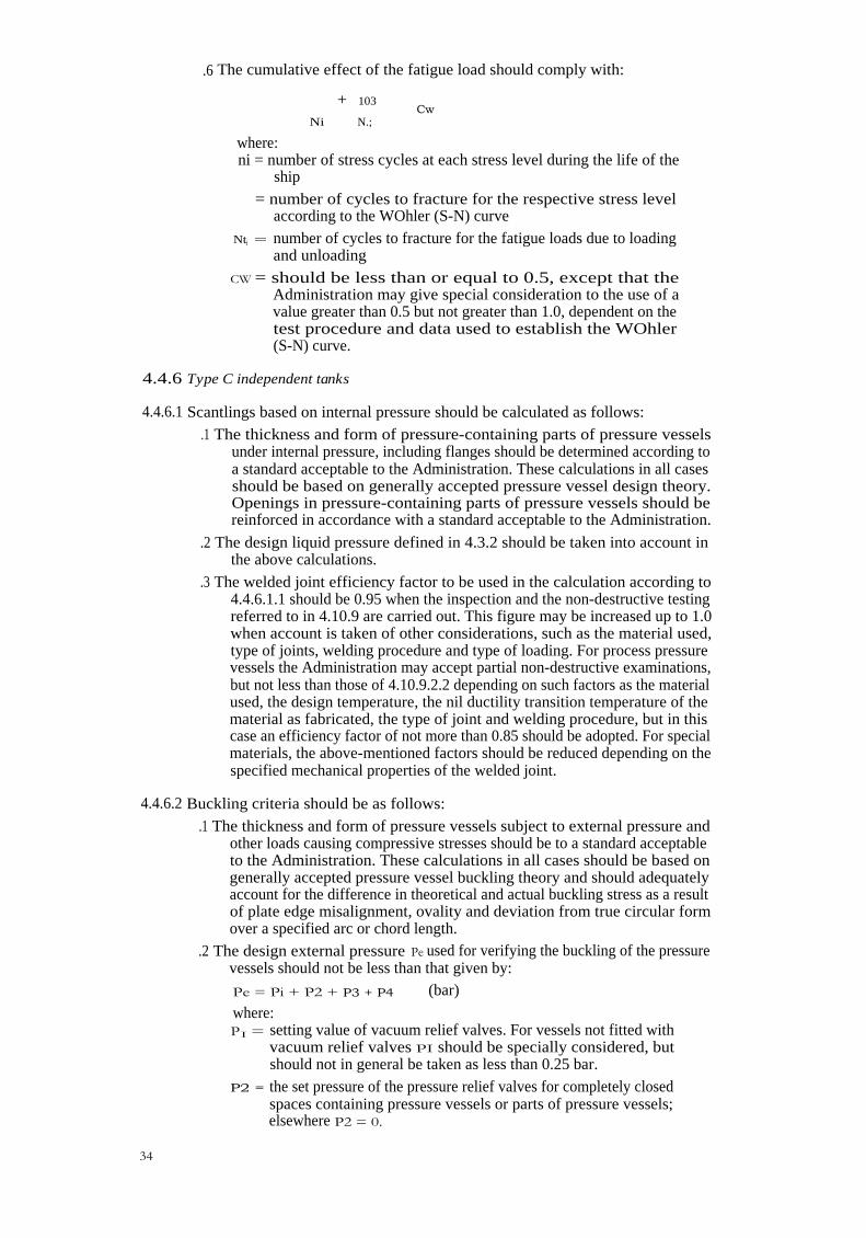
.6 The cumulative effect of the fatigue load should comply with:
+ 103Cw
Ni N.;
where:ni = number of stress cycles at each stress level during the life of the
ship
= number of cycles to fracture for the respective stress levelaccording to the WOhler (S-N) curve
Nti = number of cycles to fracture for the fatigue loads due to loadingand unloading
CW = should be less than or equal to 0.5, except that theAdministration may give special consideration to the use of avalue greater than 0.5 but not greater than 1.0, dependent on thetest procedure and data used to establish the WOhler(S-N) curve.
4.4.6 Type C independent tanks
4.4.6.1 Scantlings based on internal pressure should be calculated as follows:
.1 The thickness and form of pressure-containing parts of pressure vesselsunder internal pressure, including flanges should be determined according toa standard acceptable to the Administration. These calculations in all casesshould be based on generally accepted pressure vessel design theory.Openings in pressure-containing parts of pressure vessels should bereinforced in accordance with a standard acceptable to the Administration.
.2 The design liquid pressure defined in 4.3.2 should be taken into account inthe above calculations.
.3 The welded joint efficiency factor to be used in the calculation according to4.4.6.1.1 should be 0.95 when the inspection and the non-destructive testingreferred to in 4.10.9 are carried out. This figure may be increased up to 1.0when account is taken of other considerations, such as the material used,type of joints, welding procedure and type of loading. For process pressurevessels the Administration may accept partial non-destructive examinations,but not less than those of 4.10.9.2.2 depending on such factors as the materialused, the design temperature, the nil ductility transition temperature of thematerial as fabricated, the type of joint and welding procedure, but in thiscase an efficiency factor of not more than 0.85 should be adopted. For specialmaterials, the above-mentioned factors should be reduced depending on thespecified mechanical properties of the welded joint.
4.4.6.2 Buckling criteria should be as follows:
.1 The thickness and form of pressure vessels subject to external pressure andother loads causing compressive stresses should be to a standard acceptableto the Administration. These calculations in all cases should be based ongenerally accepted pressure vessel buckling theory and should adequatelyaccount for the difference in theoretical and actual buckling stress as a resultof plate edge misalignment, ovality and deviation from true circular formover a specified arc or chord length.
.2 The design external pressure Pe used for verifying the buckling of the pressurevessels should not be less than that given by:
Pe = Pi + P2 + P3 + P4 (bar)
where:PI = setting value of vacuum relief valves. For vessels not fitted with
vacuum relief valves PI should be specially considered, butshould not in general be taken as less than 0.25 bar.
P2 = the set pressure of the pressure relief valves for completely closedspaces containing pressure vessels or parts of pressure vessels;elsewhere P2 = 0.
34

P3 = compressive actions in the shell due to the weight andcontraction of insulation, weight of shell, including corrosionallowance, and other miscellaneous external pressure loads towhich the pressure vessel may be subjected. These include, butare not limited to, weight of domes, weight of towers and piping,effect of product in the partially filled condition, accelerationsand hull deflection. In addition the local effect of external orinternal pressure or both should be taken into account.
Pa = external pressure due to head of water for pressure vessels or partof pressure vessels on exposed decks; elsewhere P4 = 0.
4.4.6.3 Stress analysis in respect of static and dynamic loads should be performed asfollows:
.1 Pressure vessel scantlings should be determined in accordance with 4.4.6.1and .2.
.2 Calculations of the loads and stresses in way of the supports and the shellattachment of the support should be made. Loads referred to in 4.3 shouldbe used, as applicable. Stresses in way of the supports should be to a standardacceptable to the Administration. In special cases a fatigue analysis may berequired by the Administration.
.3 If required by the Administration, secondary stresses and thermal stressesshould be specially considered.
4.4.6.4 For pressure vessels, the thickness calculated according to 4.4.6.1 or the thicknessrequired by 4.4.6.2 plus the corrosion allowance, if any, should be considered as a minimumwithout any negative tolerance.
4.4.6.5 For pressure vessels, the minimum thickness of shell and heads includingcorrosion allowance, after forming, should not be less than 5 mm for carbon-manganesesteels and nickel steels, 3 mm for austenitic steels or 7 mm for aluminium alloys.
4.4.7 Internal insulation tanks
4.4.7.1 The effects of all static and dynamic loads should be considered to determine thesuitability of the tank with respect to:
fatigue failurecrack propagation from both free and supported surfacesadhesive and cohesive strengthcompressive, tensile and shear strength.
Statistical wave load analysis in accordance with 4.3.4, finite element analysis or similarmethods and fracture mechanics analysis or an equivalent approach should be carried out.
4.4.7.2.1 Special attention should be given to crack resistance and to deflections of theinner hull or independent tank structure and their compatibility with the insulationmaterials. A three-dimensional structural analysis should be carried out to the satisfactionof the Administration. This analysis is to evaluate the stress levels and deformationscontributed either by the inner hull or by the independent tank structure or both and shouldalso take into account the internal pressure as indicated in 4.3.2. Where water ballast spacesare adjacent to the inner hull forming and supporting structure of the internal insulationtank, the analysis should take account of the dynamic loads caused by water ballast underthe influence of ship motions.
4.4.7.2.2 The allowable stresses and associated deflections for the internal insulation tankand the inner hull structure or independent tank structure should be determined in eachparticular case.
4.4.7.2.3 Thicknesses of plating of the inner hull or of an independent tank should at leastcomply with the requirements of Recognized Standards, taking into account the internalpressure as indicated in 4.3.2. Tanks constructed of plane surfaces should at least complywith Recognized Standards for deep tanks.
35

4.4.7.3 A complete analysis of the response of ship, cargo and any ballast to accelerationsand motions in irregular waves of the particular ship should be performed to thesatisfaction of the Administration unless such analysis is available for a similar ship.
4.4.7.4.1 In order to confirm the design principles, prototype testing of composite modelsincluding structural elements should be carried out under combined effects of static,dynamic and thermal loads.
4.4.7.4.2 Test conditions should represent the most extreme service conditions the cargocontainment system will be exposed to during the lifetime of the ship, including thermalcycles. For this purpose, 400 thermal cycles are considered to be a minimum, based upon19 round voyages per year; where more than 19 round voyages per year are expected, ahigher number of thermal cycles will be required. These 400 thermal cycles may be dividedinto 20 full cycles (cargo temperature to 45°C) and 380 partial cycles (cargo temperatureto that temperature expected to be reached in the ballast voyage).
4.4.7.4.3 Models should be representative of the actual construction including corners,joints, pump mounts, piping penetrations and other critical areas, and should take intoaccount variations in any material properties, workmanship and quality control.
4.4.7.4.4 Combined tension and fatigue tests should be carried out to evaluate crackbehaviour of the insulation material in the case where a through crack develops in the innerhull or independent tank structure. In these tests, where applicable the crack area shouldbe subjected to the maximum hydrostatic pressure of the ballast water.
4.4.7.5 The effects of fatigue loading should be determined in accordance with 4.4.5.6 orby an equivalent method.
4.4.7.6 For internal insulation tanks, repair procedures should be developed during theprototype testing programme for both the insulation material and the inner hull or theindependent tank structure.
4.5 Allowable stresses and corrosion allowances
4.5.1 Allowable stresses
4.5.1.1 For integral tanks, allowable stresses should normally be those given for hullstructure in Recognized Standards.
4.5.1.2 For membrane tanks, reference is made to the requirements of 4.4.2.5.
4.5.1.3 For type A independent tanks primarily constructed of plane surfaces, thestresses for primary and secondary members (stiffeners, web frames, stringers, girders)when calculated by classical analysis procedures should not exceed the lower of Rm/2.66 orRe/1.33 for carbon-manganese steels and aluminium alloys, where Rm and Re are definedin 4.5.1.7. However, if detailed calculations are carried out for the primary members, theequivalent stress c as defined in 4.5.1.8 may be increased over that indicated above to astress acceptable to the Administration; calculations should take into account the effectsof bending, shear, axial and torsional deformation as well as the hull/cargo tank interactionforces due to the deflection of the double bottom and cargo tank bottoms.
4.5.1.4 For type B independent tanks, primarily constructed of bodies of revolution, theallowable stresses should not exceed:
am f
al. ...<, 1.5 flab -�, 1.5 F
ck + Crb -�, 1.5 F
GM + 6b .- 1.5F
36

where
am = equivalent primary general membrane stress
at, = equivalent primary local membrane stress
ab = equivalent primary bending stress
ARm f = the lesser of — or R
B
F = the lesser of —R.
or Re
C D
with Rm and Re as defined in 4.5.1.7. With regard to the stresses am, aL and ab see also thedefinition of stress categories in 4.13. The values of A, B, C and D should be shown on theInternational Certificate of Fitness for the Carriage of Liquefied Gases in Bulk and shouldhave at least the following minimum values:
Nickel steels andcarbon-manganese steels
Austenitic steels Aluminium alloys
A 3 3.5 4B 2 1.6 1.5C 3 3 3D 1.5 1.5 1.5
4.5.1.5 For type B independent tanks, primarily constructed of plane surfaces, theAdministration may require compliance with additional or other stress criteria.
4.5.1.6 For type C independent tanks the maximum allowable membrane stress to beused in calculation according to 4.4.6.1.1 should be the lower of:
RmA or
Re
B
where:
Rm and Re are as defined in 4.5.1.7.
The values of A and B should be shown on the International Certificate of Fitness for theCarriage of Liquefied Gases in Bulk provided for in 1.5, and should have at least theminimum values indicated in the table of 4.5.1.4.
4.5.1.7 For the purpose of 4.5.1.3, 4.5.1.4 and 4.5.1.6 the following apply:
.1 Re = specified minimum yield stress at room temperature (N/mm 2). If thestress-strain curve does not show a defined yield stress, the 0.2%proof stress applies.
Rm = specified minimum tensile strength at room temperature (N/mm2).
For welded connections in aluminium alloys the respective values of Re orRm in annealed conditions should be used.
.2 The above properties should correspond to the minimum specifiedmechanical properties of the material, including the weld metal in theas-fabricated condition. Subject to special consideration by theAdministration, account may be taken of enhanced yield stress and tensilestrength at low temperature. The temperature on which the materialproperties are based should be shown on the International Certificate ofFitness for the Carriage of Liquefied Gases in Bulk provided for in 1.5.
37

4.5.1.8 The equivalent stress crc (von Mises, Huber) should be determined by:
ac = Crx2 Cry2 ax ay + 3T x2y
where:
ax = total normal stress in x-direction
ay= total normal stress in y-direction
txy = total shear stress in x-y plane.
4.5.1.9 When the static and dynamic stresses are calculated separately and unless othermethods of calculation are justified, the total stresses should be calculated according to:
ax =
ar =
ax.st
ay.st
±
±
(ax.dyn)2
(6ydyn)2
T=xy — Txy.st ± (Txy.dyn)2
where:a
x.st, a
y.st and Txy.st = static stresses
ax.dyn,
ay.dyn and cxy.dyn = dynamic stresses
all determined separately from acceleration components and hull straincomponents due to deflection and torsion.
4.5.1.10 For internal insulation tanks, reference is made to the requirement of 4.4.7.2.
4.5.1.11 Allowable stresses for materials other than those covered by chapter 6 should besubject to approval by the Administration in each case.
4.5.1.12 Stresses may be further limited by fatigue analysis, crack propagation analysisand buckling criteria.
4.5.2 Corrosion allowances
4.5.2.1 No corrosion allowance should generally be required in addition to the thicknessresulting from the structural analysis. However, where there is no environmental controlaround the cargo tank, such as inerting, or where the cargo is of a corrosive nature, theAdministration may require a suitable corrosion allowance.
4.5.2.2 For pressure vessels no corrosion allowance is generally required if the contentsof the pressure vessel are non-corrosive and the external surface is protected by inertatmosphere or by an appropriate insulation with an approved vapour barrier. Paint orother thin coatings should not be credited as protection. Where special alloys are used withacceptable corrosion resistance, no corrosion allowance should be required. If the aboveconditions are not satisfied, the scantlings calculated according to 4.4.6 should be increasedas appropriate.
4.6 Supports
4.6.1 Cargo tanks should be supported by the hull in a manner which will prevent bodilymovement of the tank under static and dynamic loads while allowing contraction andexpansion of the tank under temperature variations and hull deflections without unduestressing of the tank and of the hull.
4.6.2 The tank with supports should also be designed for a static angle of heel of 30°without exceeding allowable stresses given in 4.5.1.
4.6.3 The supports should be calculated for the most probable largest resultingacceleration, taking into account rotational as well as translational effects. Thisacceleration in a given direction may be determined as shown in figure 4.1. The half axesof the "acceleration ellipse" should be determined according to 4.3.4.2.
38

4.6.4 Suitable supports should be provided to withstand a collision force acting on thetank corresponding to one half the weight of the tank and cargo in the forward directionand one quarter the weight of the tank and cargo in the aft direction without deformationlikely to endanger the tank structure.
4.6.5 The loads mentioned in 4.6.2 and 4.6.4 need not be combined with each other orwith wave-induced loads.
4.6.6 For independent tanks and, where appropriate, for membrane and semi-membranetanks, provision should be made to key the tanks against the rotational effects referred toin 4.6.3.
4.6.7 Antiflotation arrangements should be provided for independent tanks. Theantiflotation arrangements should be suitable to withstand an upward force caused by anempty tank in a hold space flooded to the summer load draught of the ship, without plasticdeformation likely to endanger the hull structure.
4.7 Secondary barrier
4.7.1 Where the cargo temperature at atmospheric pressure is below — 10°C, a secondarybarrier should be provided when required by 4.7.3 to act as a temporary containment forany envisaged leakage of liquid cargo through the primary barrier.
4.7.2 Where the cargo temperature at atmospheric pressure is not below — 55°C, the hullstructure may act as a secondary barrier. In such a case:
.1 the hull material should be suitable for the cargo temperature at atmosphericpressure as required by 4.9.2; and
.2 the design should be such that this temperature will not result inunacceptable hull stresses.
4.7.3 Secondary barriers in relation to tank types should normally be provided inaccordance with the following table. For tanks which differ from the basic tank types asdefined in 4.2 the secondary barrier requirements should be decided by the Administrationin each case.
Cargo temperaturat atmospheric
pressure
]0°C—10°Cand above
—10°Cdown to
—55°CBelow —55°C
No secondary Hull may act SeparateBasic tank type barrier as secondary secondary barrier
required barrier where required
Integral Tank type not normally allowed'Membrane Complete secondary barrierSemi-membrane Complete secondary barrier2Independent
Type A Complete secondary barrierType B Partial secondary barrierType C No secondary barrier required
Internal insulationType 1 Complete secondary barrierType 2 Complete secondary barrier is
incorporated
A complete secondary barrier should normally be required if cargoes with atemperature at atmospheric pressure below — 10°C are permitted inaccordance with 4.2.1.3.
2 In the case of semi-membrane tanks which comply in all respects with therequirements applicable to type B independent tanks, except for the mannerof support, the Administration may, after special consideration, accept apartial secondary barrier.
4.7.4 The secondary barrier should be so designed that:
.1 it is capable of containing any envisaged leakage of liquid cargo for a periodof 15 days, unless different requirements apply for particular voyages, takinginto account the load spectrum referred to in 4.3.4.4;
39

.2 it will prevent lowering of the temperature of the ship structure to an unsafelevel in the case of leakage of the primary barrier as indicated in 4.8.2; and
.3 the mechanism of failure for the primary barrier does not also cause thefailure of the secondary barrier and vice versa.
4.7.5 The secondary barrier should fulfil its functions at a static angle of heel of 30°.
4.7.6.1 Where a partial secondary barrier is required, its extent should be determined onthe basis of cargo leakage corresponding to the extent of failure resulting from the loadspectrum referred to in 4.3.4.4 after the initial detection of a primary leak. Due accountmay be taken of liquid evaporation, rate of leakage, pumping capacity and other relevantfactors. In all cases, however, the inner bottom in way of cargo tanks should be protectedagainst liquid cargo.
4.7.6.2 Clear of the partial secondary barrier, provision such as a spray shield should bemade to deflect any liquid cargo down into the space between the primary and secondarybarriers and to keep the temperature of the hull structure to a safe level.
4.7.7 The secondary barrier should be capable of being periodically checked for itseffectiveness, by means of a pressure/vacuum test, a visual inspection or another suitablemethod acceptable to the Administration. The method should be submitted to theAdministration for approval.
4.8 Insulation
4.8.1 Where a product is carried at a temperature below — 10°C suitable insulation shouldbe provided to ensure that the temperature of the hull structure does not fall below theminimum allowable service temperature given in chapter 6 for the grade of steel concerned,as detailed in 4.9, when the cargo tanks are at their design temperature and the ambienttemperatures are 5°C for air and 0°C for seawater. These conditions may generally be usedfor world-wide service. However, higher values of the ambient temperatures may beaccepted by the Administration for ships operated in restricted areas. Conversely, lesservalues of the ambient temperatures may be fixed by the Administration for ships tradingoccasionally or regularly to areas in latitudes where such lower temperatures are expectedduring the winter months. The ambient temperatures used in the design should be shownon the International Certificate of Fitness for the Carriage of Liquefied Gases in Bulk asprovided for in 1.5.
4.8.2 Where a complete or partial secondary barrier is required, calculations should bemade with the assumptions in 4.8.1 to check that the temperature of the hull structure doesnot fall below the minimum allowable service temperature given in chapter 6 for the gradeof steel concerned, as detailed in 4.9. The complete or partial secondary barrier should beassumed to be at the cargo temperature at atmospheric pressure.
4.8.3 Calculations required by 4.8.1 and 4.8.2 should be made assuming still air and stillwater, and except as permitted by 4.8.4, no credit should be given for means of heating. Inthe case referred to in 4.8.2, the cooling effect of the rising boil-off vapour from the leakedcargo should be considered in the heat transmission studies. For members connecting innerand outer hulls, the mean temperature may be taken for determining the steel grade.
4.8.4 In all cases referred to in 4.8.1 and 4.8.2 and for ambient temperature conditions of5°C for air and 0°C for seawater, approved means of heating transverse hull structuralmaterial may be used to ensure that the temperatures of this material do not fall below theminimum allowable values. If lower ambient temperatures are specified, approved meansof heating may also be used for longitudinal hull structural material, provided this materialremains suitable for the temperature conditions of 5°C for air and 0°C for seawater withoutheating. Such means of heating should comply with the following requirements:
.1 sufficient heat should be available to maintain the hull structure above theminimum allowable temperature in the conditions referred to in 4.8.1 and4.8.2;
.2 the heating system should be so arranged that, in the event of a failure in anypart of the system, stand-by heating could be maintained equal to not lessthan 100% of the theoretical heat load;
40

.3 the heating system should be considered as an essential auxiliary; and
.4 the design and construction of the heating system should be to thesatisfaction of the Administration.
4.8.5 In determining the insulation thickness, due regard should be paid to the amount ofacceptable boil-off in association with the reliquefaction plant on board, main propulsionmachinery or other temperature control system.
4.9 Materials
4.9.1 The shell and deck plating of the ship and all stiffeners attached thereto should bein accordance with Recognized Standards, unless the calculated temperature of thematerial in the design condition is below — 5°C due to the effect of the low temperaturecargo, in which case the material should be in accordance with table 6.5 assuming theambient sea and air temperature of 0°C and 5°C respectively. In the design condition, thecomplete or partial secondary barrier should be assumed to be at the cargo temperature atatmospheric pressure and for tanks without secondary barriers, the primary barrier shouldbe assumed to be at the cargo temperature.
4.9.2 Hull material forming the secondary barrier should be in accordance with table 6.2.Metallic materials used in secondary barriers not forming part of the hull structure shouldbe in accordance with table 6.2 or 6.3 as applicable. Insulation materials forming asecondary barrier should comply with the requirements of 4.9.7. Where the secondarybarrier is formed by the deck or side shell plating, the material grade required by table 6.2should be carried into the adjacent deck or side shell plating, where applicable, to asuitable extent.
4.9.3 Materials used in the construction of cargo tanks should be in accordance with table6.1, 6.2 or 6.3.
4.9.4 Materials other than those referred to in 4.9.1, 4.9.2 and 4.9.3 used in theconstruction of the ship which are subject to reduced temperature due to the cargo andwhich do not form part of the secondary barrier should be in accordance with table 6.5 fortemperatures as determined by 4.8. This includes inner bottom plating, longitudinalbulkhead plating, transverse bulkhead plating, floors, webs, stringers and all attachedstiffening members.
4.9.5 The insulation materials should be suitable for loads which may be imposed on themby the adjacent structure.
4.9.6 Where applicable, due to location or environmental conditions, insulation materialsshould have suitable properties of resistance to fire and flame spread and should beadequately protected against penetration of water vapour and mechanical damage.
4.9.7.1 Materials used for thermal insulation should be tested for the followingproperties as applicable, to ensure that they are adequate for the intended service:
.1 compatibility with the cargo
.2 solubility in the cargo
.3 absorption of the cargo
.4 shrinkage
.5 ageing
.6 closed cell content
.7 density
.8 mechanical properties
.9 thermal expansion
.10 abrasion
.11 cohesion
.12 thermal conductivity
.13 resistance to vibrations
.14 resistance to fire and flame spread.
41

4.9.7.2 In addition to meeting the above requirements, insulation materials which formpart of the cargo containment as defined in 4.2.5 should be tested for the followingproperties after simulation of ageing and thermal cycling to ensure that they are adequatefor the intended service:
.1 bonding (adhesive and cohesive strength)
.2 resistance to cargo pressure
.3 fatigue and crack propagation properties
.4 compatibility with cargo constituents and any other agent expected to be incontact with the insulation in normal service.
.5 where applicable the influence of presence of water and water pressure on theinsulation properties should be taken into account.
.6 gas de-absorbing.
4.9.7.3 The above properties, where applicable, should be tested for the range betweenthe expected maximum temperature in service and 5°C below the minimum designtemperature, but not lower than — 196°C.
4.9.8 The procedure for fabrication, storage, handling, erection, quality control andcontrol against harmful exposure to sunlight of insulation materials should be to thesatisfaction of the Administration.
4.9.9 Where powder or granulated insulation is used, the arrangements should be such asto prevent compacting of the material due to vibrations. The design should incorporatemeans to ensure that the material remains sufficiently buoyant to maintain the requiredthermal conductivity and also prevent any undue increase of pressure on thecontainment system.
4.10 Construction and testing
4.10.1.1 All welded joints of the shells of independent tanks should be of the butt weld,full penetration type. For dome-to-shell connections, the Administration may approve teewelds of the full penetration type. Except for small penetrations on domes, nozzle weldsare also generally to be designed with full penetration.
4.10.1.2 Welding joint details for type C independent tanks should be as follows:.1 All longitudinal and circumferential joints of pressure vessels should be of
butt welded, full penetration, double vee or single vee type. Full penetrationbutt welds should be obtained by double welding or by the use of backingrings. If used, backing rings should be removed, unless specifically approvedby the Administration for very small process pressure vessels. Other edgepreparations may be allowed by the Administration depending on the resultsof the tests carried out at the approval of the welding procedure.
.2 The bevel preparation of the joints between the pressure vessel body anddomes and between domes and relevant fittings should be designedaccording to a standard for pressure vessels acceptable to theAdministration. All welds connecting nozzles, domes or other penetrationsof the vessel and all welds connecting flanges to the vessel or nozzles shouldbe full penetration welds extending through the entire thickness of the vesselwall or nozzle wall, unless specially approved by the Administration forsmall nozzle diameters.
4.10.2 Workmanship should be to the satisfaction of the Administration. Inspection andnon-destructive testing of welds for tanks other than type C independent tanks should bein accordance with the requirements of 6.3.7.
4.10.3 For membrane tanks, quality assurance measures, weld procedure qualification,design details, materials, construction, inspection and production testing of components,should be to standards developed during the prototype testing programme.
4.10.4 For semi-membrane tanks the relevant requirements in this section forindependent tanks or for membrane tanks should be applied as appropriate.
42

4.10.5.1 For internal insulation tanks, in order to ensure uniform quality of the material,quality control procedures including environmental control, application procedurequalification, corners, penetrations and other design details, materials specification,installation and production testing of components should be to standards developedduring the prototype test programme.
4.10.5.2 A quality control specification including maximum permissible size ofconstructional defects, tests and inspections during the fabrication, installation and alsosampling tests at each of these stages should be to the satisfaction of the Administration.
4.10.6 Integral tanks should be hydrostatically or hydropneumatically tested to thesatisfaction of the Administration. The test in general should be so performed that thestresses appoximate, as far as practicable, to the design stresses and that the pressure at thetop of the tank corresponds at least to the MARV S.
4.10.7 In ships fitted with membrane or semi-membrane tanks, coffer-dams and all spaceswhich may normally contain liquid and are adjacent to the hull structure supporting themembrane should be hydrostatically or hydropneumatically tested in accordance withRecognized Standards. In addition, any other hold structure supporting the membraneshould be tested for tightness. Pipe tunnels and other compartments which do not normallycontain liquid need not be hydrostatically tested.
4.10.8.1 In ships fitted with internal insulation tanks where the inner hull is the supportingstructure, all inner hull structure should be hydrostatically or hydropheumatically testedin accordance with Recognized Standards, taking into account the MARV S.
4.10.8.2 In ships fitted with internal insulation tanks where independent tanks are thesupporting structure, the independent tanks should be tested in accordance with 4.10.10.1.
4.10.8.3 For internal insulation tanks where the inner hull structure or an independenttank structure acts as a secondary barrier, a tightness test of those structures should becarried out using techniques to the satisfaction of the Administration.
4.10.8.4 These tests should be performed before the application of the materials which willform the internal insulation tank.
4.10.9 For type C independent tanks, inspection and non-destructive testing should beas follows:
.1 Manufacture and workmanship—The tolerances relating to manufactureand workmanship such as local out-of-roundness deviations from the trueform, welded joints alignment and tapering of plates having differentthicknesses, should comply with standards acceptable to the Administration.The tolerances should also be related to the buckling analysis referred to in4.4.6.2.
.2 Non-destructive testing—As far as completion and extension of non-destructive testing of welded joints are concerned, the extent of non-destructive testing should be total or partial according to standardsacceptable to the Administration, but the controls to be carried out shouldnot be less than the following:
.2.1 Total non-destructive testing referred to in 4.4.6.1.3:
Radiography:
butt welds 100% and
Surface crack detection:
all welds 10%
reinforcement rings around holes, nozzles, etc. 100%
As an alternative, ultrasonic testing may be accepted as a partial substitutefor the radiographic testing, if specially allowed by the Administration. Inaddition, the Administration may require total ultrasonic testing on weldingor reinforcement rings around holes, nozzles, etc.
43

.2.2 Partial non-destructive testing referred to in 4.4.6.1.3:
Radiography:
butt welds: all welded crossing joints and at least 10% of the full lengthat selected positions uniformly distributed and
Surface crack detection:
reinforcement rings around holes, nozzles etc. 100%.
Ultrasonic testing:
as may be required by the Administration in each instance.
4.10.10 Each independent tank should be subjected to a hydrostatic or hydropneumatictest as follows:
.1 For type A independent tanks, this test should be so performed that thestresses approximate, as far as practicable, to the design stresses and that thepressure at the top of the tank corresponds at least to the MARV S. Whena hydropneumatic test is performed, the conditions should simulate, as faras practicable, the actual loading of the tank and its supports.
.2 For type B independent tanks, the test should be performed as required in4.10.10.1 for type A independent tanks. In addition, the maximum primarymembrane stress or maximum bending stress in primary members under testconditions should not exceed 90% of the yield strength of the material (asfabricated) at the test temperature. To ensure that this condition is satisfied,when calculations indicate that this stress exceeds 75% of the yield strength,the prototype test should be monitored by the use of strain gauges or othersuitable equipment.
.3 Type C independent tanks should be tested as follows:
.3.1 Each pressure vessel, when completely manufactured, should be subjected toa hydrostatic test at a pressure measured at the top of the tanks, of not lessthan 1.5 P., but in no case during the pressure test should the calculatedprimary membrane stress at any point exceed 90% of the yield stress of thematerial. The definition of P. is given in 4.2.6. To ensure that this conditionis satisfied where calculations indicate that this stress will exceed 0.75 timesthe yield strength, the prototype test should be monitored by the use of straingauges or other suitable equipment in pressure vessels other than simplecylindrical and spherical pressure vessels.
.3.2 The temperature of the water used for the test should be at least 30°C abovethe nil ductility transition temperature of the material as fabricated.
.3.3 The pressure should be held for 2 h per 25 mm of thickness but in no caseless than 2 h.
.3.4 Where necessary for cargo pressure vessels, and with the specific approvalof the Administration, a hydropneumatic test may be carried out under theconditions prescribed in 4.10.10.3.1, .2 and .3.
.3.5 Special consideration may be given by the Administration to the testing oftanks in which higher allowable stresses are used, depending on servicetemperature. However, the requirements of 4.10.10.3.1 should be fullycomplied with.
.3.6 After completion and assembly, each pressure vessel and its related fittingsshould be subjected to an adequate tightness test.
.3.7 Pneumatic testing of pressure vessels other than cargo tanks should beconsidered on an individual case basis by the Administration. Such testingshould be permitted only for those vessels which are so designed orsupported that they cannot be safely filled with water, or for those vesselswhich cannot be dried and are to be used in a service where traces of thetesting medium cannot be tolerated.
44

4.10.11 All tanks should be subjected to a tightness test which may be performed incombination with the pressure test referred to in 4.10.10 or separately.
4.10.12 Requirements with respect to inspection of secondary barriers should be decidedby the Administration in each case.
4.10.13 In ships fitted with type B independent tanks, at least one tank and its supportshould be instrumented to confirm stress levels unless the design and arrangement for thesize of ship involved are supported by full-scale experience. Similar instrumentation maybe required by the Administration for type C independent tanks dependent on theirconfiguration and on the arrangement of their supports and attachments.
4.10.14 The overall performance of the cargo containment system should be verified forcompliance with the design parameters during the initial cool-down, loading anddischarging of the cargo. Records of the performance of the components and equipmentessential to verify the design parameters should be maintained and be available to theAdministration.
4.10.15 Heating arrangements, if fitted in accordance with 4.8.4, should be tested forrequired heat output and heat distribution.
4.10.16 The hull should be inspected for cold spots following the first loaded voyage.
4.10.17 The insulation materials of internal insulation tanks should be subjected toadditional inspection in order to verify their surface conditions after the third loadedvoyage of the ship, but not later than the first 6 months of the ship's service after buildingor a major repair work is undertaken on the internal insulation tanks.
4.10.18 For type C independent tanks, the required marking of the pressure vessel shouldbe achieved by a method which does not cause unacceptable local stress rises.
4.11 Stress relieving for type C independent tanks
4.11.1 For type C independent tanks of carbon and carbon-manganese steel, post-weldheat treatment should be performed after welding if the design temperature is below -10°C.Post-weld heat treatment in all other cases and for materials other than those mentionedabove should be to the satisfaction of the Administration. The soaking temperature andholding time should be to the satisfaction of the Administration.
4.11.2 In the case of large cargo pressure vessels of carbon or carbon-manganese steel forwhich it is difficult to perform the heat treatment, mechanical stress relieving bypressurizing may be carried out as an alternative to the heat treatment with the approvalof the Administation and subject to the following conditions:
.1 Complicated welded pressure vessel parts such as sumps or domes withnozzles, with adjacent shell plates should be heat treated before they arewelded to larger parts of the pressure vessel.
.2 The plate thicknesses should not exceed those given by a standard acceptableto the Administration.
.3 The performance of a detailed stress analysis to ascertain that the maximumprimary membrane stress during the mechanical stress relieving, closelyapproaches, but does not exceed, 90% of the yield stress of the material.Strain measurements during the stress relief pressurization may be requiredby the Administration for verifying the calculations.
.4 The procedure for mechanical stress relieving should be submittedbeforehand to the Administration for approval.
4.12 Guidance formulae for acceleration components
The following formulae are given as guidance for the components of acceleration dueto ship's motions corresponding to a probability level of 10- 8 in the North Atlantic andapply to ships with a length exceeding 50 m.
45

Vertical acceleration as defined in 4.3.4.6
az = ± ao ,V 45 2•2 0.6 1 5
1 + (5.3 — ) (—+ 0.05) (—)Lo Lo CB
Transverse acceleration as defined in 4.3.4.6
ay = ± ao.V 0.6 + 2.5 (--0 + 0.05)2 + K (1 + 0.6 Kf)
2
:
Longitudinal acceleration as defined in 4.3.4.6
ax = ± ao V0.6 + A2 — 0.25 A
with:
A = (0.7 — Lo + 5 z ) ( 0.6 )
1200 Lo CB
where:Lo = length of the ship for determination of scantlings as defined in
Recognized Standards (m)
CB = block coefficient
B = greatest moulded breadth of the ship (m)
x = longitudinal distance (m) from amidships to the centre of gravityof the tank with contents; x is positive forward of amidships,negative aft of amidships
z = vertical distance (m) from the ship's actual waterline to the centreof gravity of tank with contents; z is positive above and negativebelow the waterline.
60034 —
V Loao = 0.2— +
V—Lo Lo
where: V = service speed (knots)
K = 1 in general. For particular loading conditions and hull forms,determination of K according to the formula below may benecessary.
K = 13GM/B, where K ?.... 1.0 and GM = metacentric height (m)
ax, ay and a, = maximum dimensionless accelerations
(i.e. relative to the acceleration of gravity) in the respective directions and theyare considered as acting separately for calculation purposes. az does notinclude the component due to the static weight, ay includes the component dueto the static weight in the transverse direction due to rolling and ax includes thecomponent due to the static weight in the longitudinal direction due topitching.
4.13 Stress categories
For the purpose of stress evaluation referred to in 4.5.1.4, stress categories are definedin this section.
46

4.13.1 Normal stress is the component of stress normal to the plane of reference.
4.13.2 Membrane stress is the component of normal stress which is uniformly distributedand equal to the average value of the stress across the thickness of the section underconsideration.
4.13.3 Bending stress is the variable stress across the thickness of the section underconsideration, after the subtraction of the membrane stress.
4.13.4 Shear stress is the component of the stress acting in the plane of reference.
4.13.5 Primary stress is a stress produced by the imposed loading and which is necessaryto balance the external forces and moments. The basic characteristic of a primary stress isthat it is not self-limiting. Primary stresses which considerably exceed the yield strength willresult in failure or at least in gross deformations.
4.13.6 Primary general membrane stress is a primary membrane stress which is sodistributed in the structure that no redistribution of load occurs as a result of yielding.
4.13.7 Primary local membrane stress arises where a membrane stress produced bypressure or other mechanical loading and associated with a primary or a discontinuityeffect produces excessive distortion in the transfer of loads for other portions of thestructure. Such a stress is classified as a primary local membrane stress although it has somecharacteristics of a secondary stress. A stress region may be considered as local if:
SI 0.5 AIIIT and
S2 2.5 Arftt and
where:
Si = distance in the meridional direction over which the equivalentstress exceeds 1.1 f
S2 = distance in the meridional direction to another region where thelimits for primary general membrane stress are exceeded
R = mean radius of the vessel
t = wall thickness of the vessel at the location where the primarygeneral membrane stress limit is exceeded
f = allowable primary general membrane stress.
4.13.8 Secondary stress is a normal stress or shear stress developed by constraints ofadjacent parts or by self-constraint of a structure. The basic characteristic of a secondarystress is that it is self-limiting. Local yielding and minor distortions can satisfy theconditions which cause the stress to occur.
47

I CI.
CG Of TANK
ao = resulting acceleration (static and dynamic) in arbitrary direction 0ay = transverse component of accelerationa, = vertical component of acceleration
Figure 4.1—Acceleration ellipse
6 zv
Figure 4.2—Determination of internal pressure heads
YV
v.
4 8

10' 2.10'
0.
ao = most probable stress over the life of the shipResponse cycle scale is logarithmic; the value of 2.10 5 is givenas an example of estimate.
Figure 4.3—Simplified load distribution
49

CHAPTER 5—PROCESS PRESSURE VESSELS AND LIQUID,VAPOUR, AND PRESSURE PIPING SYSTEMS
5.1 General
5.1.1 Administrations should take appropriate steps to ensure uniformity in theimplementation and application of the provisions of this chapter.'
5.1.2 The requirements for type C independent tanks in chapter 4 may also apply toprocess pressure vessels if required by the Administration. If so required the term "pressurevessels" as used in chapter 4 covers both type C independent tanks and process pressurevessels.
5.2 Cargo and process piping
5.2.1 General
5.2.1.1 The requirements of this section apply to product and process piping includingvapour piping and vent lines of safety valves or similar piping. Instrument piping notcontaining cargo is exempt from these requirements.
5.2.1.2 Provision should be made by the use of offsets, loops, bends, mechanicalexpansion joints such as bellows, slip joints and ball joints or similar suitable means toprotect the piping, piping system components and cargo tanks from excessive stresses dueto thermal movement and from movements of the tank and hull structure. Wheremechanical expansion joints are used in piping they should be held to a minimum and,where located outside cargo tanks, should be of the bellows type.
5.2.1.3 Low-temperature piping should be thermally isolated from the adjacent hullstructure, where necessary, to prevent the temperature of the hull from falling below thedesign temperature of the hull material. Where liquid piping is dismantled regularly, orwhere liquid leakage may be anticipated, such as at shore connections and at pump seals,protection for the hull beneath should be provided.
5.2.1.4 Where tanks or piping are separated from the ship's structure by thermalisolation, provision should be made for electrically bonding both the piping and the tanks.All gasketed pipe joints and hose connections should be electrically bonded.
5.2.1.5 Suitable means should be provided to relieve the pressure and remove liquidcontents from cargo loading and discharging crossover headers and cargo hoses to thecargo tanks or other suitable location, prior to disconnecting the cargo hoses.
5.2A.6 All pipelines or components which may be isolated in a liquid full conditionshould be provided with relief valves.
5.2.1.7 Relief valves discharging liquid cargo from the cargo piping system shoulddischarge into the cargo tanks; alternatively they may discharge to the cargo vent mast ifmeans are provided to detect and dispose of any liquid cargo which may flow into the ventsystem. Relief valves on cargo pumps should discharge to the pump suction.
5.2.2 Scantlings based on internal pressure
5.2.2.1 Subject to the conditions stated in 5.2.4, the wall thickness of pipes should not beless than:
to + b + ct =
1 — a100
1Reference is made to the published Rules of members and associate members of the International Association of
Classification Societies and in particular to IACS Unified Requirement No. G3.
(mm)
50

where:
to = theoretical thickness
to = PD/(20 Ke + P) (mm)
with:
P = design pressure (bar) referred to in 5.2.3
D = outside diameter (mm)
K= allowable stress (N/mm2) referred to in 5.2.4
e = efficiency factor equal 1.0 for seamless pipes and for longitudinally or spirallywelded pipes, delivered by approved manufacturers of welded pipes, whichare considered equivalent to seamless pipes when non-destructive testing onwelds is carried out in accordance with Recognized Standards. In other casesan efficiency factor value depending on the manufacturing process may bedetermined by the Administration.
b = allowance for bending (mm). The value of b should be chosen so that the calculatedstress in the bend, due to internal pressure only, does not exceed the allowable stress.Where such justification is not given, b should be:
b = Dto (mm)
2.5r
with:
r = mean radius of the bend (mm)
c = corrosion allowance (mm). If corrosion or erosion is expected, the wall thickness ofthe piping should be increased over that required by other design requirements. Thisallowance should be consistent with the expected life of the piping.
a = negative manufacturing tolerance for thickness (%).
5.2.3 Design pressure
5.2.3.1 The design pressure P in the formula for to in 5.2.2.1 is the maximum gaugepressure to which the system may be subjected in service.
5.2.3.2 The greater of the following design conditions should be used for piping, pipingsystem and components as appropriate:
.1 for vapour piping systems or components which may be separated from theirrelief valves and which may contain some liquid: the saturated vapourpressure at 45°C, or higher or lower if agreed upon by the Administration(see 4.2.6.2);
.2 for systems or components which may be separated from their relief valvesand which contain only vapour at all times: the superheated vapour pressureat 45°C or higher or lower if agreed upon by the Administration (see 4.2.6.2),assuming an initial condition of saturated vapour in the system at the systemoperating pressure and temperature; or
.3 the MARV S of the cargo tanks and cargo processing systems; or
.4 the pressure setting of the associated pump or compressor discharge reliefvalve; or
.5 the maximum total discharge or loading head of the cargo piping system; or
.6 the relief valve setting on a pipeline system.
51

5.2.3.3 The design pressure should not be less than 10 bar gauge except for open endedlines where it should be not less than 5 bar gauge.
5.2.4 Permissible stresses
5.2.4.1 For pipes, the permissible stress to be considered in the formula for t in 5.2.2.1 isthe lower of the following values:
Rm ReOr
A B
where:Rm = specified minimum tensile strength at room temperature (N/mm2)Re = specified minimum yield stress at room temperature (N/mm2). If the stress-
strain curve does not show a defined yield stress, the 0.2% proof stressapplies.
The values of A and B should be shown on the International Certificate of Fitness for theCarriage of Liquefied Gases in Bulk as provided for in 1.5 and have values of at least A =2.7 and B = 1.8.
5.2.4.2 The minimum wall thickness should be in accordance with RecognizedStandards.
5.2.4.3 Where necessary for mechanical strength to prevent damage, collapse, excessivesag or buckling of pipes due to superimposed loads from supports, ship deflection or othercauses, the wall thickness should be increased over that required by 5.2.2, or, if this isimpracticable or would cause excessive local stresses, these loads should be reduced,protected against or eliminated by other design methods.
5.2.4.4 Flanges, valves and other fittings should be to a standard acceptable to theAdministration, taking into account the design pressure defined in 5.2.2. For bellowsexpansion joints used in vapour services, a lower minimum design pressure may beaccepted by the Administration.
5.2.4.5 For flanges not complying with a standard, the dimensions of flanges and relatedbolts should be to the satisfaction of the Administration.
5.2.5 Stress analysis
When the design temperature is —110°C or lower, a complete stress analysis, taking intoaccount all the stresses due to weight of pipes, including acceleration loads if significant,internal pressure, thermal contraction and loads induced by hog and sag of the ship foreach branch of the piping system should be submitted to the Administration. Fortemperatures of above —110°C, a stress analysis may be required by the Administration inrelation to such matters as the design or stiffness of the piping system and the choice ofmaterials. In any case, consideration should be given to thermal stresses, even thoughcalculations are not submitted. The analysis may be carried out according to a code ofpractice acceptable to the Administration.
5.2.6 Materials
5.2.6.1 The choice and testing of materials used in piping systems should comply with therequirements of chapter 6 taking into account the minimum design temperature. However,some relaxation may be permitted in the quality of material of open ended vent piping,provided the temperature of the cargo at the pressure relief valve setting is —55°C or greaterand provided no liquid discharge to the vent piping can occur. Similar relaxations may bepermitted under the same temperature conditions to open ended piping inside cargo tanks,excluding discharge piping and all piping inside membrane and semi-membrane tanks.
5.2.6.2 Materials having a melting point below 925°C should not be used for pipingoutside the cargo tanks except for short lengths of pipes attached to the cargo tanks, inwhich case fire-resisting insulation should be provided.
52

5.3 Type tests on piping components
5.3.1 Each type of piping component should be subject to type tests.
5.3.2.1 Each size and type of valve intended to be used at a working temperature below—55°C should be subjected to a tightness test to the minimum design temperature or lower,and to a pressure not lower than the design pressure of the valve. During the test thesatisfactory operation of the valve should be ascertained.
5.3.2.2 The following type tests should be performed on each type of expansion bellowsintended for use on cargo piping outside the cargo tank and, where required, on thoseexpansion bellows installed within the cargo tanks:
.1 A type element of the bellows, not precompressed, should be pressure testedat not less than 5 times the design pressure without bursting. The durationof the test should not be less than 5 min.
.2 A pressure test should be performed on a type expansion joint complete withall the accessories such as flanges, stays and articulations, at twice the designpressure at the extreme displacement conditions recommended by themanufacturer without permanent deformation. Depending on the materialsused, the Administration may require the test to be at the minimum designtemperature.
.3 A cyclic test (thermal movements) should be performed on a completeexpansion joint, which is to successfully withstand at least as many cycles,under the conditions of pressure, temperature, axial movement, rotationalmovement and transverse movement, as it will encounter in actual service.Testing at ambient temperature is permitted, when this testing is at least assevere as testing at the service temperature.
.4 A cyclic fatigue test (ship deformation) should be performed on a completeexpansion joint, without internal pressure, by simulating the bellowsmovement corresponding to a compensated pipe length, for at least2,000,000 cycles at a frequency not higher than 5 cycles/s. This test is onlyrequired when, due to the piping arrangement, ship deformation loads areactually experienced.
.5 The Administration may waive performance of the tests referred to in thisparagraph provided that complete documentation is supplied to establish thesuitability of the expansion joints to withstand the expected workingconditions. When the maximum internal pressure exceeds 1.0 bar gauge thisdocumentation is to include sufficient test data to justify the design methodused, with particular reference to correlation between calculation and testresults.
5.4 Piping fabrication and joining details
5.4.1 The requirements of this section apply to piping inside and outside the cargo tanks.However, the Administration may accept relaxations from these requirements for pipinginside cargo tanks and open ended piping.
5.4.2 The following direct connection of pipe lengths, without flanges, may be considered:
.1 Butt welded joints with complete penetration at the root may be used in allapplications. For design temperatures below — 10°C, butt welds should beeither double welded or equivalent to a double welded butt joint. This maybe accomplished by use of a backing ring, consumable insert or inert gasback-up on the first pass. For design pressure in excess of 10 bar and designtemperature of — 10°C or lower, backing rings should be removed.
.2 Slip-on welded joints with sleeves and related welding, having dimensionssatisfactory to the Administration, should only be used for open ended lineswith external diameter of 50 mm or less and design temperatures not lowerthan — 55°C.
.3 Screwed couplings acceptable to the Administration should only be used foraccessory lines and instrumentation lines with external diameters of 25 mmor less.
53

5.4.3.1 Flanges in flange connections should be of the welded neck, slip-on or socketwelded type.
5.4.3.2 Flanges should comply with standards acceptable to the Administration as totheir type, manufacturer and test. In particular, for all piping except open ended, thefollowing restrictions apply:
.1 For design temperatures lower than — 55°C, only welded neck flanges shouldbe used.
.2 For design temperatures lower than — 10°C, slip-on flanges should not beused in nominal sizes above 100 mm and socket welded flanges should notbe used in nominal sizes above 50 mm.
5.4.4 Piping connections, other than those mentioned in 5.4.2 and .3, may be accepted bythe Administration in each case.
5.4.5 Bellows and expansion joints should be provided to allow for expansion of piping..1 If necessary, bellows should be protected against icing.
.2 Slip joints should not be used except within the cargo tanks.
5.4.6 Welding, post-weld heat treatments and non-destructive testing.
.1 Welding should be carried out in accordance with 6.3.
.2 Post-weld heat treatments should be required for all butt welds of pipes madewith carbon, carbon-manganese and low alloy steels. The Administrationmay waive the requirement for thermal stress relieving of pipes having wallthickness less than 10 mm in relation to the design temperature and pressureof the piping system concerned.
.3 In addition to normal controls before and during the welding and to thevisual inspection of the finished welds, as necessary for proving that thewelding has been carried out correctly and according to the requirements ofthis paragraph, the following tests should be required:
.3.1 100% radiographic inspection of butt welded joints for piping systems withservice temperatures lower than — 10°C and with inside diameters of morethan 75 mm or wall thicknesses greater than 10 mm.
.3.2 For other butt welded joints of pipes, spot radiographic tests or other non-destructive tests should be carried out at the discretion of the Administrationdepending upon service, position and materials. In general, at least 10% ofbutt welded joints of pipes should be radiographed.
5.5 Testing of piping
5.5.1 The requirements of this section apply to piping inside and outside the cargo tanks.However, the Administration may accept relaxations from these requirements for pipinginside cargo tanks and open ended piping.
5.5.2 After assembly, all cargo and process piping should be subjected to a hydrostatictest to at least 1.5 times the design pressure. When piping systems or parts of systems arecompletely manufactured and equipped with all fittings, the hydrostatic test may beconducted prior to installation aboard ship. Joints welded on board should behydrostatically tested to at least 1.5 times the design pressure. Where water cannot betolerated and the piping cannot be dried prior to putting the system into service, proposalsfor alternative testing fluids or testing means should be submitted to the Administrationfor approval.
5.5.3 After assembly on board, each cargo and process piping system should be subjectedto a leak test using air, halides, or other suitable medium to a pressure depending on theleak detection method applied.
5.5.4 All piping systems including valves, fittings and associated equipment for handlingcargo or vapours should be tested under normal operating conditions not later than at thefirst loading operation.
54

5.6 Cargo system valving requirements
5.6.1 Every cargo piping system and cargo tank should be provided with the followingvalves, as applicable:
.1 For cargo tanks with a MARV S not exceeding 0.7 bar gauge, all liquid andvapour connections, except safety relief valves and liquid level gaugingdevices, should have shutoff valves located as close to the tank as practicable.These valves may be remotely controlled but should be capable of localmanual operation and provide full closure. One or more remotely controlledemergency shutdown valves should be provided on the ship for shuttingdown liquid and vapour cargo transfer between ship and shore. Such valvesmay be arranged to suit the ship's design and may be the same valve asrequired in 5.6.3 and should comply with the requirements of 5.6.4.
.2 For cargo tanks with a MARV S exceeding 0.7 bar gauge, all liquid andvapour connections, except safety relief valves and liquid level gaugingdevices, should be equipped with a manually operated stop valve and aremotely controlled emergency shutdown valve. These valves should belocated as close to the tank as practicable. Where the pipe size does notexceed 50 mm in diameter, excess flow valves may be used in lieu of theemergency shutdown valve. A single valve may be substituted for the twoseparate valves provided the valve complies with the requirements of 5.6.4,is capable of local manual operation and provides full closure of the line.
.3 Cargo pumps and compressors should be arranged to shutdownautomatically if the emergency shutdown valves required by 5.6.1.1 and .2are closed by the emergency shutdown system required by 5.6.4.
5.6.2 Cargo tank connections for gauging or measuring devices and not be equipped withexcess flow or emergency shutdown valves provided that the devices are so constructed thatthe outward flow of tank contents cannot exceed that passed by a 1.5mm diametercircular hole.
5.6.3 One remotely operated emergency shutdown valve should be provided at each cargohose connection in use. Connections not used in transfer operations may be blinded withblank flanges in lieu of valves.
5.6.4 The control system for all required emergency shutdown valves should be soarranged that all such valves may be operated by single controls situated in at least tworemote locations on the ship. One of these locations should be the control position requiredby 13.1.3 or cargo control room. The control system should also be provided with fusibleelements designed to melt at temperatures between 98°C and 104°C which will cause theemergency shutdown valves to close in the event of fire. Locations for such fusible elementsshould include the tank domes and loading stations. Emergency shutdown valves shouldbe of the fail-closed (closed on loss of power) type and be capable of local manual closingoperation. Emergency shutdown valves in liquid piping should fully close under all serviceconditions within 30 s of actuation. Information about the closing time of the valves andtheir operating characteristics should be available on board and the closing time should beverifiable and reproducible. Such valves should close smoothly.
5.6.5 Excess flow valves should close automatically at the rated closing flow of vapour orliquid as specified by the manufacturer. The piping including fittings, valves, andappurtenances protected by an excess flow valve, should have a greater capacity than therated closing flow of the excess flow valve. Excess flow valves may be designed with a bypassnot exceeding an area of 1.0 mm diameter circular opening to allow equalisation pressure,after an operating shutdown.
5.7 Ship's cargo hoses
5.7.1 Liquid and vapour hoses used for cargo transfer should be compatible with thecargo and suitable for the cargo temperature.
5.7.2 Hoses subject to tank pressure, or the discharge pressure of pumps or vapourcompressors, should be designed for a bursting pressure not less than five times themaximum pressure the hose will be subjected to during cargo transfer.
55

5.7.3 Each new type of cargo hose, complete with end fittings, should be prototype testedto a pressure not less than five times its specified maximum working pressure. The hosetemperature during this prototype test should be the intended extreme service temperature.Hoses used for prototype testing should not be used for cargo service. Thereafter, beforebeing placed in service, each new length of cargo hose produced should be hydrostaticallytested at ambient temperature to a pressure not less than 1.5 times its specified maximumworking pressure nor more than two fifths its bursting pressure. The hose should bestencilled or otherwise marked with its specified maximum working pressure and, if usedin other than ambient temperature services, its maximum or minimum service temperatureor both. The specified maximum working pressure should not be less than 10 bar gauge.
5.8 Cargo transfer methods
5.8.1 Where cargo transfer is by means of cargo pumps not accessible for repair with thetanks in service, at least two separate means should be provided to transfer cargo from eachcargo tank and the design should be such that failure of one cargo pump, or means oftransfer, will not prevent the cargo transfer by another pump or pumps, or other cargotransfer means.
5.8.2 The procedure for transfer of cargo by gas pressurization should preclude lifting ofthe relief valves during such transfer. Gas pressurization may be accepted as a means oftransfer of cargo for those tanks so designed that the design factor of safety is not reducedunder the conditions prevailing during the cargo transfer operation.
5.9 Vapour return connections
Connections for vapour return lines to the shore installations should be provided.
56

CHAPTER 6—MATERIALS OF CONSTRUCTION
6.1 General
6.1.1 Administrations should take appropriate steps to ensure uniformity in theimplementation and application of the provisions of this chapter.'
6.1.2 This chapter gives the requirements for plates, sections, pipes, forgings, castings andweldments used in the construction of cargo tanks, cargo process pressure vessels, cargoand process piping, secondary barriers and contiguous hull structures associated with thetransportation of the products. The requirements for rolled materials, forgings andcastings are given in 6.2 and tables 6.1 to 6.5. The requirements for weldments are givenin 6.3.
6.1.3 The manufacture, testing, inspection and documentation should be in accordancewith Recognized Standards and the specific requirements given in this Code.
6.1.4.1 Acceptance tests should include Charpy V-notch toughness tests unless otherwisespecified by the Administration. The specified Charpy V-notch requirements are minimumaverage energy values for three full size (10 mm x 10 mm) specimens and minimum singleenergy values for individual specimens. Dimensions and tolerances of Charpy V-notchspecimens should be in accordance with Recognized Standards. The testing andrequirements for specimens smaller than 5.0 mm size should be in accordance withRecognized Standards. Minimum average values for sub-sized specimens should be:
Charpy V-notch Minimum energy averagespecimen size of three specimens
10 x 10 mm E10 x 7.5 mm 5/6E10 x 5.0 nun 2/3E
where: E = the energy values (J) specified in tables 6.1 to 6.4.
Only one individual value may be below the specified average value provided it is not lessthan 70% of that value.
6.1.4.2 In all cases, the largest size Charpy specimens possible for the material thicknessshould be machined with the specimens located as near as practicable to a point midwaybetween the surface and the centre of the thickness and the length of the notchperpendicular to the surface (see figure 6.1). If the average value of the three initial CharpyV-notch specimens fails to meet the stated requirements, or the value for more than onespecimen is below the required average value, or when the value for one specimen is belowthe minimum value permitted for a single specimen, three additional specimens from thesame material may be tested and the results combined with those previously obtained toform a new average. If this new average complies with the requirements and if no more thantwo individual results are lower than the required average and no more than one result islower than the required value for a single specimen, the piece or batch may be accepted. Atthe discretion of the Administration other types of toughness tests, such as a drop weighttest, may be used. This may be in addition to or in lieu of the Charpy V-notch test.
6.1.5 Tensile strength, yield stress and elongation should be to the satisfaction of theAdministration. For carbon-manganese steel and other materials with definitive yieldpoint, consideration should be given to the limitation of the yield to tensile ratio.
6.1.6 The bend test may be omitted as a material acceptance test, but is required forweld tests.
'Reference is made to the published Rules of members and associate members of the International Association ofClassification Societies and in particular to IACS Unified Requirement No. WI.
57

6.1.7 Materials with alternative chemical composition or mechanical properties may beaccepted by the Administration.
6.1.8 Where post-weld heat treatment is specified or required, the properties of the basematerial should be determined in the heat treated condition in accordance with theapplicable table of this chapter and the weld properties should be determined in the heattreated condition in accordance with 6.3. In cases where a post-weld heat treatment isapplied, the test requirements may be modified at the discretion of the Administration.
6.1.9 Where reference is made in this chapter to A, B, D, E, AH, DH and EH hullstructural steels, these steel grades are hull structural steels according to RecognisedStandards.
6.2 Material requirements
The requirements for materials of construction are shown in the tables as follows:Table 6.1:
Table 6.2:
Table 6.3:
Table 6.4:
Table 6.5:
Plates, pipes (seamless and welded), sections and forgings for cargotanks and process pressure vessels for design temperatures not lowerthan 0°C.Plates, sections and forgings for cargo tanks, secondary barriers andprocess pressure vessels for design temperatures below 0°C and downto –55°C.Plates, sections and forgings for cargo tanks, secondary barriers andprocess pressure vessels for design temperatures below –55°C and downto –165°C.Pipes (seamless and welded), forgings and castings for cargo processpiping for design temperatures below 0°C and down to –165°C.Plates and sections for hull structures required by 4.9.1 and 4.9.4.
58

Table 6.1
PLATES, PIPES (SEAMLESS AND WELDED),' SECTIONS AND FORGINGSFOR CARGO TANKS AND PROCESS PRESSURE VESSELS FOR
DESIGN TEMPERATURES NOT LOWER THAN 0°C
CHEMICAL COMPOSITION AND HEAT TREATMENTCARBON-MANGANESE STEEL Fully killedFine grain steel where thickness exceeds 20 mmSmall additions of alloying elements by agreement with the AdministrationComposition limits to be approved by the AdministrationNormalised, or quenched and tempered 2
TENSILE AND TOUGHNESS (IMPACT) TEST REQUIREMENTSPLATES Each "piece" to be testedSECTIONS AND FORGINGS Batch testTENSILE PROPERTIES Specified minimum yield stress not to exceed 410
N/mm2 3CHARPY V-NOTCH TEST PLATE Transverse test pieces. Minimum average
energy value (E) 27 JSECTIONS AND FORGINGS Longitudinal test pieces. Minimum average
energy value (E) 41 JTEST TEMPERATURE: Thickness t (mm) Test temperature (°C)
t < 20 020 < t < 40 —20
NOTES1 For seamless pipes and fittings normal practice applies. The use of longitudinally and
spirally welded pipes should be specially approved by the Administration.2 A controlled rolling procedure may be used as an alternative to normalising or
quenching and tempering, subject to special approval by the Administration.3 Materials with specified minimum yield stress exceeding 410 N/mm 2 may be specially
approved by the Administration. For these materials, particular attention should begiven to the hardness of the weld and heat affected zone.
59
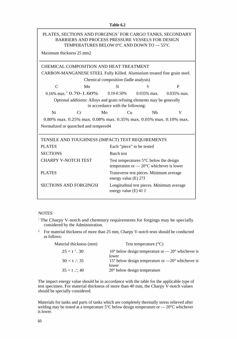
Table 6.2
PLATES, SECTIONS AND FORGINGS 1 FOR CARGO TANKS, SECONDARYBARRIERS AND PROCESS PRESSURE VESSELS FOR DESIGN
TEMPERATURES BELOW 0°C AND DOWN TO — 55°C
Maximum thickness 25 mm2
CHEMICAL COMPOSITION AND HEAT TREATMENT
CARBON-MANGANESE STEEL Fully Killed. Aluminium treated fine grain steel.
Chemical composition (ladle analysis)
C Mn Si S P
0.16% max. 3 0.70-1.60% 0.10-0.50% 0.035% max. 0.035% max.
Optional additions: Alloys and grain refining elements may be generallyin accordance with the following:
Ni Cr Mo Cu Nb V
0.80% max. 0.25% max. 0.08% max. 0.35% max. 0.05% max. 0.10% max.
Normalized or quenched and tempered4
TENSILE AND TOUGHNESS (IMPACT) TEST REQUIREMENTS
PLATES
SECTIONS
CHARPY V-NOTCH TEST
PLATES
SECTIONS AND FORGINGSI
Each "piece" to be tested
Batch test
Test temperatures 5°C below the designtemperature or — 20°C whichever is lower
Transverse test pieces. Minimum averageenergy value (E) 27J
Longitudinal test pieces. Minimum averageenergy value (E) 41 J
NOTES1 The Charpy V-notch and chemistry requirements for forgings may be specially
considered by the Administration.2 For material thickness of more than 25 mm, Charpy V-notch tests should be conducted
as follows:
Material thickness (mm) Test temperature (°C)
25 < t ‘. 30 10° below design temperature or — 20° whichever islower
30 < t .�. 35 15° below design temperature or —20° whichever islower
35 < t ..�, 40 20° below design temperature
The impact energy value should be in accordance with the table for the applicable type oftest specimen. For material thickness of more than 40 mm, the Charpy V-notch valuesshould be specially considered.
Materials for tanks and parts of tanks which are completely thermally stress relieved afterwelding may be tested at a temperature 5°C below design temperature or — 20°C whicheveris lower.
60

For thermally stress relieved reinforcements and other fittings, the test temperature shouldbe the same as that required for the adjacent tank-shell thickness.
3 By special agreement with the Administration, the carbon content may be increased to0.18% maximum provided the design temperature is not lower than — 40°C.
4 A controlled rolling procedure may be used as an alternative to normalizing orquenching and tempering, subject to special approval by the Administration.
Guidance:
For materials exceeding 25 mm in thickness for which the test temperature is — 60°C orlower, the application of specially treated steels or steels in accordance with table 6.3 maybe necessary.
61

Table 6.3
PLATES, SECTIONS AND FORGINGS 1 FOR CARGO TANKS, SECONDARYBARRIERS AND PROCESS PRESSURE VESSELS FOR DESIGN
TEMPERATURES BELOW — 55°C AND DOWN TO —165°C 2
Maximum thickness 25 mm 3
Minimum designtemp. (0°C)
Chemical composition and heat treatment Impact test temp.(°C)
— 60 1.5% nickel steel—normalized — 65
— 65 2.25% nickel steel—normalized or normalizedand tempered 5
— 70
— 90 3.5% nickel steel—normalized or normalizedand tempered 5
— 95
— 105 5% nickel steel—normalized or normalizedand tempered 5'6
—110
— 165 9% nickel steel—double normalized andtempered or quenched and tempered
— 196
— 165 Austenitic steels, such as types 304, 304L, 316,316L, 321 and 347 solution treated 7
— 196
— 165 Aluminium alloys; such as type 5083 annealed Not required
— 165 Austenitic Fe—Ni alloy (36% nickel)Heat treatment as agreed
Not required
TENSILE AND TOUGHNESS (IMPACT) TEST REQUIREMENTS
PLATES Each "piece" to be tested
SECTIONS AND FORGINGS Batch test
CHARPY V-NOTCH TEST
PLATES Transverse test pieces. Minimum averageenergy value (E) 27 J
SECTIONS AND FORGINGS Longitudinal test pieces. Minimum averageenergy value (E) 41 J
NOTES
I The impact test required for forgings used in critical applications should be subject tospecial consideration by the Administration.
2 The requirements for design temperatures below — 165°C should be specially agreedwith the Administration.
3 For materials 1.5% Ni, 2.25% Ni, 3.5% Ni and 5% Ni, with thicknesses greater than 25mm, the impact tests should be conducted as follows:
Material thickness (mm) Test temperature (°C)
25 < t < 30 10° below design temperature30 < t ..�. 35 15° below design temperature35 < t < 40 20° below design temperature
62

In no case should the test temperature be above that indicated in the table.
The energy value should be in accordance with the table for the applicable type of testspecimen. For material thickness of more than 40 mm, the Charpy V-notch valuesshould be specially considered.
For 9% Ni, austenitic stainless steels and aluminium alloys, thicknesses greater than25 mm may be used at the discretion of the Administration.
4 The chemical composition limits should be approved by the Administration.
5 A lower minimum design temperature for quenched and tempered steels may byspecially agreed with the Administration.
6 A specially heat treated 5% nickel steel, for example triple heat treated 5% nickel steel,may be used down to —165°C upon special agreement with the Administration,provided that the impact tests are carried out at —196°C.
7 The impact test may be omitted subject to agreement with the Administration.
63

Table 6.4
PIPES (SEAMLESS AND WELDED), 1 FORGINGS2 AND CASTINGS2FOR CARGO AND PROCESS PIPING FOR DESIGN TEMPERATURES
BELOW 0°C AND DOWN TO —165°C 3
Maximum thickness 25 mm
Impact Test
Minimumdesign
temp. (0°C)
Chemical composition s andheat treatment
TestTemp. (°C)
Minimumaverage energy
(E) (J)
— 55 Carbon-manganese steel. Fullykilled fine grain. Normalized or asagreed6
4 27
— 65 2.25% nickel steel. Normalized ornormalized and tempered6
— 70 34
— 90 3.5% nickel steel. Normalized ornormalized and tempered6
— 95 34
— 165 9% nickel steel7 . Doublenormalized and tempered orquenched and tempered
— 196 41
Austenitic steels, such as types 304,304L, 316, 316L, 321 and 347.Solution treated 8
— 196 41
Aluminium alloys, such as type5083 annealed
Not required
TENSILE AND TOUGHNESS (IMPACT) TEST REQUIREMENTSEach batch to be testedIMPACT TEST—Longitudinal test pieces.
NOTES
The use of longitudinally or spirally welded pipes should be specially approved by theAdministration.
2 The requirements for forgings and castings may be subject to special consideration bythe Administration.
3 The requirements for design temperatures below — 165°C should be specially agreedwith the Administration.
4 The test temperature should be 5°C below the design temperature or — 20°C whicheveris lower.
5 The composition limits should be approved by the Administration.
6 A lower design temperature may be specially agreed with the Administration forquenched and tempered materials.
7 This chemical composition is not available for castings.
8 Impact tests may be omitted subject to agreement with the Administration.
64

Table 6.5
PLATES AND SECTIONS FOR HULL STRUCTURESREQUIRED BY 4.9.1 AND 4.9.4
Minimum design temperatureof hull structure (°C)
Maximum thickness (mm) for steel gradesin accordance with 6.1.9
A B D E AH DH EH
0 and above I
— 5 and above 2
Normal Practice
down to — 5 15 25 30 50 25 45 50
down to — 10 x 20 25 50 20 40 50
down to — 20 x x 20 50 x 30 50
down to — 30 x x x 40 x 20 40
Below — 30 In accordance with table 6.2 except that the thicknesslimitation given in table 6.2 and in footnote 2 of thattable does not apply.
NOTES
"x" means steel grate not to be used.
For the purpose of 4.9.4
2 For the purpose of 4.9.1
6.3 Welding and non-destructive testing
6.3.1 General
The requirements of this section are those generally employed for carbon, carbon-manganese, nickel alloy and stainless steels, and may form the basis for acceptance testingof other material. At the discretion of the Administration, impact testing of stainless steeland aluminium alloy weldments may be omitted and other tests may be specially requiredfor any material.
6.3.2 Welding consumables
Welding consumables intended for welding of cargo tanks should be in accordancewith Recognised Standards unless otherwise agreed with the Administration. Depositedweld metal tests and butt weld tests should be required for all welding consumables, unlessotherwise specially agreed with the Administration. The results obtained from tensile andCharpy V-notch impact tests should be in accordance with Recognized Standards. Thechemical composition of the deposited weld metal should be recorded for information andapproval.
65

6.3.3 Welding procedure tests for cargo tanks and process pressure vessels
6.3.3.1 Welding procedure tests for cargo tanks and process pressure vessels are requiredfor all butt welds and the test assemblies should be representative of:
each base material
each type of consumable and welding process
each welding position.
For butt welds in plates, the test assemblies should be so prepared that the rolling directionis parallel to the direction of welding. The range of thickness qualified by each weldingprocedure test should be in accordance with Recognized Standards. Radiographic orultrasonic testing may be performed at the option of the fabricator or the Administration.Procedure tests for consumables intended for fillet welding should be in accordance withRecognized Standards. In such cases consumables should be selected which exhibitsatisfactory impact properties.
6.3.3.2 The following welding procedure tests for cargo tanks and process pressurevessels should be made from each test assembly:
.1 Cross-weld tensile tests.
.2 Transverse bend tests which may be face, root or side bends at the discretionof the Administration. However, longitudinal bend tests may be required inlieu of transverse bend tests in cases where the base material and weld metalhave different strength levels.
.3 One set of three Charpy V-notch impacts, generally at each of the followinglocations, as shown in figure 6.1:
Centreline of the welds
Fusion line (F.L.)
1 mm from the F.L.
3 mm from the F.L.
5 mm from the F.L.
.4 Macrosection, microsection and hardness survey may also be required by theAdministration.
6.3.4 Test requirements
6.3.4.1 Tensile tests: Generally, tensile strength should not be less than the specifiedminimum tensile strength for the appropriate parent materials. The Administration mayalso require that the transverse weld tensile strength should not be less than the specifiedminimum tensile strength for the weld metal, where the weld metal has a lower tensilestrength than that of the parent metal. In every case, the position of fracture is to bereported for information.
6.3.4.2 Bend tests: No fracture is acceptable after a 180° bend over a former of a diameterfour times the thickness of the test pieces, unless otherwise specially required by or agreedwith the Administration.
6.3.4.3 Charpy V-notch impact tests: Charpy tests should be conducted at thetemperature prescribed for the base material being joined. The results of weld impact tests,minimum average energy (E), should be no less than 27 J. The weld metal requirements forsubsize specimens and single energy values should be in accordance with 6.1.4. The resultsof fusion line and heat affected zone impact tests should show a minimum average energy(E) in accordance with the transverse or longitudinal requirements of the base material,whichever is applicable, and for subsize specimens, the minimum average energy (E) shouldbe in accordance with 6.1.4. If the material thickness does not permit machining either full-size or standard subsize specimens, the testing procedure and acceptance standards shouldbe in accordance with Recognized Standards.
66

6.3.5 Welding procedure tests for piping
Welding procedure tests for piping should be carried out and should be similar to thosedetailed for cargo tanks in 6.3.3. Unless otherwise specially agreed with theAdministration, the test requirements should be in accordance with 6.3.4.
6.3.6 Production weld tests
6.3.6.1 For all cargo tanks and process pressure vessels except integral and membranetanks, production weld tests should generally be performed for approximately each 50 mof butt weld joints and should be representative of each welding position. For secondarybarriers, the same type production tests as required for primary tanks should be performedexcept that the number of tests may be reduced subject to agreement with theAdministration. Tests, other than those specified in 6.3.6.2, .3 and .4, may be required forcargo tanks or secondary barriers at the discretion of the Administration.
6.3.6.2 The production tests for types A and B independent tanks and semi-membranetanks should include the following tests:
.1 Bend tests, and where required for procedure tests one set of three CharpyV-notch tests should be made for each 50 m of weld. The Charpy V-notchtests should be made with specimens having the notch alternately located inthe centre of the weld and in the heat affected zone (most critical locationbased on procedure qualification results). For austenitic stainless steel, allnotches should be in the centre of the weld.
.2 The test requirements are the same as the applicable test requirements listedin 6.3.4 except that impact tests that do not meet the prescribed energyrequirements may still be accepted, upon special consideration by theAdministration, by passing a drop weight test. In such cases, two drop weightspecimens should be tested for each set of Charpy specimens that failed andboth must show "no break" performance at the temperature at which theCharpy tests were conducted.
6.3.6.3 In addition to those tests listed in 6.3.6.1 for type C independent tanks andprocess pressure vessels, transverse weld tensile tests are required. The test requirementsare listed in 6.3.4 except that impact tests that do not meet the prescribed energyrequirements may still be accepted upon special consideration by the Administration, bypassing a drop weight test. In such cases, two drop weight specimens should be tested foreach set of Charpy specimens that failed, and both must show "no break" performance atthe temperature at which the Charpy tests were conducted.
6.3.6.4 Production tests for integral and membrane tanks should be in accordance withRecognized Standards.
6.3.7 Non-destructive testing
6.3.7.1 For type A independent tanks and semi-membrane tanks where the designtemperature is —20°C or less, and for type B independent tanks regardless of temperature,all full penetration butt welds of the shell plating of cargo tanks should be subjected to100% radiographic inspection.
6.3.7.1.1 Where the design temperature is higher than — 20°C, all full penetration buttwelds in way of intersections and at least 10% of the remaining full penetration welds oftank structures should be subjected to radiographic inspection.
6.3.7.1.2 In each case the remaining tank structure including the welding of stiffeners andother fittings and attachments should be examined by magnetic particle or dye penetrantmethods as considered necessary by the Administration.
6.3.7.1.3 All test procedures and acceptance standards should be in accordance withRecognized Standards. The Administration may accept an approved ultrasonic testprocedure in lieu of radiographic inspection, but may in addition require supplementaryinspection by radiography at selected locations. Further, the Administration may requireultrasonic testing in addition to normal radiographic inspection.
67

Single—V butt weld
( Specimen
S. Specimen
6.3.7.2 Inspection of type C independent tanks and process pressure vessels should becarried out in accordance with 4.10.9.
6.3.7.3 For integral and membrane tanks, special weld inspection procedures andacceptance criteria should be in accordance with Recognized Standards.
6.3.7.4 The inspection and non-destructive testing of the inner hull or the independenttank structures supporting internal insulation tanks should take into account the designcriteria given in 4.4.7. The schedule for inspection and non-destructive testing should be tothe satisfaction of the Administration.
6.3.7.5 Inspection of piping should be carried out in accordance with the requirementsof chapter 5.
6.3.7.6 The secondary barrier should be radiographed as considered necessary by theAdministration. Where the outer shell of the hull is part of the secondary barrier, all sheerstrake butts and the intersections of all butts and seams in the side shell should be testedby radiography.
2nd welded side
1st welded side
Notch location:
1 Centre of weld
2 On fusion line
3 In HAZ, 1 mm from fusion line
4 In HAZ, 3 mm from fusion line
5 In HAZ, 5 mm from fusion line
HAZ = heat affected zone
The largest size Charpy specimens possible for the material thickness should bemachined with the centre of the specimens located as near as practicable to a pointmidway between the surface and the centre of the thickness. In all cases, the distancefrom the surface of the material to the edge of the specimen should be approximatelyone mm or greater. In addition for double-V butt welds, specimens should be machinedcloser to the surface of the second welded side.
Figure 6.1—Orientation of weld test specimen
68

CHAPTER 7—CARGO PRESSURE/TEMPERATURE CONTROL
7.1 General
7.1.1 Unless the entire cargo system is designed to withstand the full gauge vapourpressure of the cargo under conditions of the upper ambient design temperatures,maintenance of the cargo tank pressure below the MARV S should be provided by one ormore of the following means, except as otherwise provided in this section:
.1 a system which regulates the pressure in the cargo tanks by the use ofmechanical refrigeration;
.2 a system whereby the boil-off vapours are utilized as fuel for shipboard useor waste heat system subject to the provisions of chapter 16. This system maybe used at all times, including while in port and while manoeuvring, providedthat a means of disposing of excess energy is provided, such as a steam dumpsystem, that is satisfactory to the Administration;
.3 a system allowing the product to warm up and increase in pressure. Theinsulation or cargo tank design pressure or both should be adequate toprovide for a suitable margin for the operating time and temperaturesinvolved. The system should be acceptable to the Administration in eachcase;
.4 other systems acceptable to the Administration;
.5 in addition to the above means, the Administration may permit certaincargoes to be controlled by venting cargo vapours to the atmosphere at sea.This may also be permitted in port with the permission of the portAdministration.
7.1.2 The systems required by 7.1.1 should be constructed, fitted and tested to thesatisfaction of the Administration. Materials used in their construction should be suitablefor use with the cargoes to be carried. For normal service, the upper ambient designtemperature should be:
sea 32°Cair 45°C.
For service in especially hot or cold zones these design temperatures should be increasedor reduced, as appropriate, by the Administration.
7.1.3 For certain highly dangerous cargoes specified in chapter 17, the cargo containmentsystem should be capable of withstanding the full vapour pressure of the cargo underconditions of the upper ambient design temperatures irrespective of any system providedfor dealing with boil-off gas.
7.2 Refrigeration systems
7.2.1 A refrigeration system should consist of one or more units capable of maintainingthe required cargo pressure/temperature under conditions of the upper ambient designtemperatures. Unless an alternative means of controlling the cargo pressure/temperatureis provided to the satisfaction of the Administration, a stand-by unit (or units) affordingspare capacity at least equal to the largest required single unit should be provided. A stand-by unit should consist of a compressor with its driving motor, control system and anynecessary fittings to permit operation independently of the normal service units. A stand-by heat exchanger should be provided unless the normal heat exchanger for the unit hasan excess capacity of at least 25% of the largest required capacity. Separate piping systemsare not required.
7.2.2.1 Where two or more refrigerated cargoes which may react chemically in adangerous manner are carried simultaneously, special consideration should be given to therefrigeration systems to avoid the possibility of mixing cargoes. For the carriage of suchcargoes, separate refrigeration systems, each complete with a stand-by unit as specified in7.2.1, should be provided for each cargo. However, where cooling is provided by an indirector combined system and leakage in the heat exchangers cannot cause mixing of the cargoesunder any envisaged condition, separate refrigeration units need not be fitted.
69

7.2.2.2 Where two or more refrigerated cargoes are not mutually soluble under theconditions of carriage, so that their vapour pressures would be additive on mixing, specialconsideration should be given to the refrigeration systems to avoid the possibility of mixingcargoes.
7.2.3 Where cooling water is required in refrigeration systems, an adequate supply shouldbe provided by a pump or pumps used exclusively for this purpose. This pump or thesepumps should have at least two sea suction lines, where practicable leading from sea-chests,one port and one starboard. A spare pump of adequate capacity should be provided, whichmay be a pump used for other services so long as its use for cooling would not interferewith any other essential service.
7.2.4 The refrigeration system may be arranged in one of the following ways:.1 a direct system where evaporated cargo is compressed, condensed and
returned to cargo tanks. For certain cargoes specified in chapter 17 thissystem should not be used;
.2 an indirect system where cargo or evaporated cargo is cooled or condensedby refrigerant without being compressed;
.3 a combined system where evaporated cargo is compressed and condensed ina cargo/refrigerant heat exchanger and returned to the cargo tanks. Forcertain cargoes specified in chapter 17 this system should not be used.
7.2.5 All primary and secondary refrigerants must be compatible with each other and withthe cargo with which they come into contact. The heat exchange may take place eitherremotely from the cargo tank or by cooling coils fitted inside or outside the cargo tank.
70

CHAPTER 8—CARGO TANK VENT SYSTEMS
8.1 General
All cargo tanks should be provided with a pressure relief system appropriate to thedesign of the cargo containment system and the cargo being carried. Hold spaces,interbarrier spaces and cargo piping which may be subject to pressures beyond their designcapabilities should also be provided with a suitable pressure relief system. The pressurerelief system should be connected to a vent piping system so designed as to minimize thepossibility of cargo vapour accumulating on the decks, or entering accommodation spaces,service spaces, control stations and machinery spaces, or other spaces where it may createa dangerous condition. Pressure control systems specified by chapter 7 should beindependent of the pressure relief valves.
8.2 Pressure relief systems
8.2.1 Each cargo tank with a volume exceeding 20 m3 should be fitted with at least twopressure relief valves of approximately equal capacity, suitably designed and constructedfor the prescribed service. For cargo tanks with a volume not exceeding 20 m 3, a single reliefvalve may be fitted.
8.2.2 Interbarrier spaces should be provided with pressure relief devices to the satisfactionof the Administration.
8.2.3 The setting of the pressure relief valves should not be higher than the vapourpressure which has been used in the design of the tank.
8.2.4 Pressure relief valves should be connected to the highest part of the cargo tank abovedeck level. Pressure relief valves on cargo tanks with a design temperature below 0°Cshould be arranged to prevent their becoming inoperative due to ice formation when theyare closed. Due consideration should be given to the construction and arrangement ofpressure relief valves on cargo tanks subject to low ambient temperatures.
8.2.5 Pressure relief valves should be prototype tested to ensure that the valves have thecapacity required. Each valve should be tested to ensure that it opens at the prescribedpressure setting with an allowance not exceeding ± 10% for 0 to 1.5 bar, ± 6% for 1.5 to3.0 bar, ± 3% for 3.0 bar and above. Pressure relief valves should be set and sealed by acompetent authority acceptable to the Administration and a record of this action,including the values of set pressure, should be retained aboard the ship.
8.2.6 In the case of cargo tanks permitted to have more than one relief valve setting thismay be accomplished by:
.1 installing two or more properly set and sealed valves and providing meansas necessary for isolating the valves not in use from the cargo tank; or
.2 installing relief valves whose settings may be changed by the insertion ofpreviously approved spacer pieces or alternative springs or by other similarmeans not requiring pressure testing to verify the new set pressure. All othervalve adjustments should be sealed.
8.2.7 The changing of the set pressure under the provisions of 8.2.6 should be carried outunder the supervision of the master in accordance with procedures approved by theAdministration and specified in the ship's operating manual. Changes in set pressuresshould be recorded in the ship's log and a sign posted in the cargo control room, if provided,and at each relief valve, stating the set pressure.
8.2.8 Stop valves or other means of blanking off pipes between tanks and pressure reliefvalves to facilitate maintenance should not be fitted unless all the following arrangementsare provided:
.1 suitable arrangements to prevent more than one pressure relief valve beingout of service at the same time;
.2 a device which automatically and in a clearly visible way indicates which oneof the pressure relief valves is out of service; and
71

.3 pressure relief valve capacities such that if one valve is out of service theremaining valves have the combined relieving capacity required by 8.5.However, this capacity may be provided by the combined capacity of allvalves, if a suitably maintained valve is carried on board.
8.2.9 Each pressure relief valve installed on a cargo tank should be connected to a ventingsystem, which should be so constructed that the discharge of gas will be directed upwardsand so arranged as to minimize the possibility of water or snow entering the vent system.The height of vent exits should be not less than B/3 or 6 m whichever is greater, above theweather deck and 6 m above the working area and the fore and aft gangway.
8.2.10 Cargo tank pressure relief valve vent exits should be arranged at a distance of atleast equal to B or 25 m, whichever is less, from the nearest air intake or opening toaccommodation spaces, service spaces and control stations, or other gas-safe spaces. Forships less than 90 m in length, smaller distances may be permitted by the Administration.All other vent exits connected to the cargo containment system should be arranged at adistance of at least 10 m from the nearest air intake or opening to accommodation spaces,service spaces and control stations, or other gas-safe spaces.
8.2.11 All other cargo vent exits not dealt with in other chapters should be arranged inaccordance with 8.2.9 and 8.2.10.
8.2.12 If cargoes which react in a hazardous manner with each other are carriedsimultaneously, a separate pressure relief system should be fitted for each cargo carried.
8.2.13 In the vent piping system, means for draining liquid from places where it mayaccumulate should be provided. The pressure relief valves and piping should be so arrangedthat liquid can under no circumstances accumulate in or near the pressure relief valves.
8.2.14 Suitable protection screens should be fitted on vent outlets to prevent the ingressof foreign objects.
8.2.15 All vent piping should be so designed and arranged that it will not be damaged bytemperature variations to which it may be exposed, or by the ship's motions.
8.2.16 The back pressure in the vent lines from the pressure relief valves should be takeninto account in determining the flow capacity required by 8.5.
8.2.17 Pressure relief valves should be positioned on the cargo tank so that they willremain in the vapour phase under conditions of 15° list and 0.015 L trim, where L is asdefined in 1.3.23.
8.3 Additional pressure relieving system for liquid level control
8.3.1 Where required by 15.1.4.2, an additional pressure relieving system to prevent thetank from becoming liquid full at any time during relief under the fire exposure conditionsreferred to in 8.5 should be fitted to each tank. This pressure relieving system shouldconsist of:
.1 one or more relief valves set at a pressure corresponding to the gauge vapourpressure of the cargo at the reference temperature defined in 15.1.4.2; and
.2 an override arrangement, whenever necessary, to prevent its normaloperation. This arrangement should include fusible elements designed tomelt at temperatures between 98°C and 104°C and to cause relief valvesspecified in 8.3.1.1 to become operable. The fusible elements should belocated, in particular, in the vicinity of relief valves. The system shouldbecome operable upon loss of system power if provided. The overridearrangement should not be dependent on any source of ship's power.
8.3.2 The total relieving capacity of the additional pressure relieving system at thepressure mentioned in 8.3.1.1 should not be less than:
Q' = FG ,Ao.82 (m3/0
72

where:
Q' = minimum required rate of discharge of air at standard conditions of 273 Kand 1.013 bar.
(L + prin)D V M
with:pr = relative density of liquid phase of product at relieving conditions (pr = 1.0
for fresh water);m = — di/dpr = gradient of decrease of liquid phase enthalpy against increase
of liquid phase density (kJ/kg) at relieving conditions. For set pressures nothigher than 2.0 bar the values in table 8.1 may be used. For products notlisted in the table and for higher set pressures, the value of m should becalculated on the basis of the thermodynamic data of the product itself;
i = enthalpy of liquid (kJ/kg);T' = temperature in kelvins (K) at relieving conditions, i.e. at the pressure at
which the additional pressure relieving system is set;
F, A, L, D, Z and M are defined in 8.5.2.
8.3.3 Compliance with 8.3.1.1 requires changing of the setting of the relief valves providedfor in this section. This should be accomplished in accordance with the provisions of 8.2.6and 8.2.7.
8.3.4 Relief valves mentioned under 8.3.1.1 above may be the same as the pressure reliefvalves mentioned in 8.2, provided the setting pressure and the relieving capacity are incompliance with the requirements of this section.
8.3.5 The exhaust of such pressure relief valves may be led to the venting system referredto in 8.2.9. If separate venting arrangements are fitted these should be in accordance withthe requirements of 8.2.9 to 8.2.15.
Table 8.1—Factor m
Product m = -di/dPr
(kJ/kg)
Ammonia, anhydrous 3400Butadiene 1800Butane 2000Butylenes 1900Ethane 2100Ethylene 1500Methane 2300Methyl chloride 816Nitrogen 400Propane 2000Propylene 1600Propylene oxide 1550Vinyl chloride 900
The values in this table may be used for setpressures not higher than 2.0 bar.
8.4 Vacuum protection systems
8.4.1 Cargo tanks designed to withstand a maximum external pressure differentialexceeding 0.25 bar and capable of withstanding the maximum external pressure differentialwhich can be attained at maximum discharge rates with no vapour return into the cargotanks, or by operation of a cargo refrigeration system, need no vacuum relief protection.
12.4 Z.T'G' =
73

8.4.2 Cargo tanks designed to withstand a maximum external pressure differential notexceeding 0.25 bar, or tanks which cannot withstand the maximum external pressuredifferential that can be attained at maximum discharge rates with no vapour return intothe cargo tanks, or by operation of a cargo refrigeration system, or by sending boil-offvapour to the machinery spaces, should be fitted with:
.1 two independent pressure switches to sequentially alarm and subsequentlystop all suction of cargo liquid or vapour from the cargo tank, andrefrigeration equipment if fitted, by suitable means at a pressure sufficientlybelow the maximum external designed pressure differential of the cargo tank;or
.2 vacuum relief valves with a gas flow capacity at least equal to the maximumcargo discharge rate per cargo tank, set to open at a pressure sufficientlybelow the external design differential pressure of the cargo tank; or
.3 other vacuum relief sytems acceptable to the Administration.
8.4.3 Subject to the requirements of chapter 17, the vacuum relief valves should admit aninert gas, cargo vapour or air to the cargo tank and should be arranged to minimize thepossibility of the entrance of water or snow. If cargo vapour is admitted, it should be froma source other than the cargo vapour lines.
8.4.4 The vacuum protection system should be capable of being tested to ensure that itoperates at the prescribed pressure.
8.5 Size of valves
Pressure relief valves should have a combined relieving capacity for each cargo tank todischarge the greater of the following with not more than a 20% rise in cargo tank pressureabove the MARV S:
.1 the maximum capacity of the cargo tank inerting system if the maximumattainable working pressure of the cargo tank inerting system exceeds theMARV S of the cargo tanks; or
.2 vapours generated under fire exposure computed using the followingformula:
Q = FGA° .82 (m3/s)
where:
minimum required rate of discharge of air at standard conditions of273 K and 1.013 bar.
F = fire exposure factor for different cargo tank types:
F = 1.0 for tanks without insulation located on deck;
F = 0.5 for tanks above the deck when insulation is approved by theAdministration. (Approval will be based on the use of an approvedfireproofing material, the thermal conductance of insulation, and itsstability under fire exposure);
F = 0.5 for uninsulated independent tanks installed in holds;
F = 0.2 for insulated independent tanks in holds (or uninsulatedindependent tanks in insulated holds);
F = 0.1 for insulated independent tanks in inerted holds (or uninsulatedindependent tanks in inerted, insulated holds);
F = 0.1 for membrane and semi-membrane tanks.
For independent tanks partly protruding through the open deck, the fire exposurefactor should be determined on the basis of the surface areas above and below deck.
74

G = gas factor
G = 12.4 Z.TLD M
with:T = temperature in kelvins (K) at relieving conditions, i.e. 120% of the
pressure at which the pressure relief valve is set.L = latent heat of the material being vaporized at relieving conditions, in
kJ/kgD = constant based on relation of specific heats k, shown in table 8.2; if k
is not known, D = 0.606 should be used. The constant D may also becalculated by the following formula:
k + 1 ( 2 ) k - 1
D= Vk k + 1Z = compressibility factor of the gas at relieving conditions; if not known,Z = 1.0 should be used.M = molecular mass of the product
A = external surface area of the tank (m 2) for different tank types:for body-of-revolution type tanks:
A = external surface area;for other than body-of-revolution type tanks:
A = external surface area less the projected bottom surfacearea;
for tanks consisting of an array of pressure vessel tanks:—insulation on the ship's structure:
A = external surface area of the hold less its projected area;—insulation of the tank structure:
A = external surface area of the array of pressure vesselsexcluding insulation, less the projected bottom area asshown in figure 8.1.
75

Table 8.2-Constant D
k D k D
1.00 0.606 1.52 0.7041.02 0.611 1.54 0.7071.04 0.615 1.56 0.7101.06 0.620 1.58 0.7131.08 0.624 1.60 0.7161.10 0.628 1.62 0.7191.12 0.633 1.64 0.7221.14 0.637 1.66 0.7251.16 0.641 1.68 0.7281.18 0.645 1.70 0.7311.20 0.649 1.72 0.7341.22 0.652 1.74 0.7361.24 0.656 1.76 0.7391.26 0.660 1.78 0.7421.28 0.664 1.80 0.7451.30 0.667 1.82 0.7471.32 0.671 1.84 0.7501.34 0.674 1.86 0.7521.36 0.677 1.88 0.7551.38 0.681 1.90 0.7581.40 0.685 1.92 0.7601.42 0.688 1.94 0.7631.44 0.691 1.96 0.7651.46 0.695 1.98 0.7671.48 0.698 2.00 0.7701.50 0.701 2.02 0.772
2.20 0.792
tan entli nes
Figure 8.1
76

CHAPTER 9—ENVIRONMENTAL CONTROL
9.1 Environmental control within cargo tanks and cargo piping systems
9.1.1 A piping system should be provided to enable each cargo tank to be safely gas-freed,and to be safely purged with cargo gas from a gas-free condition. The system should bearranged to minimize the possibility of pockets of gas or air remaining after gas-freeing orpurging.
9.1.2 A sufficient number of gas sampling points should be provided for each cargo tankin order to adequately monitor the progress of purging and gas-freeing. Gas samplingconnections should be valved and capped above the main deck.
9.1.3 For flammable gases, the system should be arranged to minimize the possibility ofa flammable mixture existing in the cargo tank during any part of the gas-freeing operationby utilizing an inerting medium as an intermediate step. In addition, the system shouldenable the cargo tank to be purged with an inerting medium prior to filling with cargovapour or liquid, without permitting a flammable mixture to exist at any time within thecargo tank.
9.1.4 Piping systems which may contain cargo should be capable of being gas-freed andpurged as provided in 9.1.1 and 9.1.3.
9.1.5 Inert gas utilized in these procedures may be provided from the shore or from theship.
9.2 Environmental control within the hold spaces (cargo containment systems other than typeC independent tanks)
9.2.1 Interbarrier and hold spaces associated with cargo containment systems forflammable gases requiring full secondary barriers should be inerted with a suitable dry inertgas and kept inerted with make-up gas provided by a shipboard inert gas generationsystem, or by shipboard storage which should be sufficient for normal consumption for atleast 30 days.
9.2.2.1 Interbarrier and hold spaces associated with cargo containment systems forflammable gases requiring partial secondary barriers should be inerted with suitable dryinert gas and kept inerted with make-up gas provided by a shipboard inert gas generationsystem or by shipboard storage which should be sufficient for normal consumption for atleast 30 days.
9.2.2.2 Alternatively, subject to the restrictions specified in chapter 17, theAdministration may allow the spaces referred to in 9.2.2.1 to be filled with dry air providedthat the ship maintains a stored charge of inert gas or is fitted with an inert gas generationsystem sufficient to inert the largest of these spaces; and provided that the configuration ofthe spaces and the relevant vapour detection systems, together with the capability of theinerting arrangements, ensure that any leakage from the cargo tanks will be rapidlydetected and inerting effected before a dangerous condition can develop. Equipment forthe provision of sufficient dry air of suitable quality to satisfy the expected demand shouldbe provided.
9.2.3 For non-flammable gases, the spaces referred to in 9.2.1 and 9.2.2.1 may bemaintained with a suitable dry air or inert atmosphere.
9.2.4 In case of internal insulation tanks, environmental control arrangements are notrequired for interbarrier spaces and spaces between the secondary barrier and the inner hullor independent tank structures completely filled with insulation materials complyingwith 4.9.7.2.
9.3 Environmental control of spaces surrounding type C independent tanks
Spaces surrounding refrigerated cargo tanks not having secondary barriers should befilled with suitable dry inert gas or dry air and be maintained in this condition with make-up inert gas provided by a shipboard inert gas generation system, shipboard storage of inertgas, or dry air provided by suitable air drying equipment.
77
9.4 Inerting
9.4.1 Inerting refers to the process of providing a non-combustible environment by theaddition of compatible gases, which may be carried in storage vessels or produced on boardthe ship or supplied from the shore. The inert gases should be compatible chemically andoperationally, at all temperatures likely to occur within the spaces to be inerted, with thematerials of construction of the spaces and the cargo. The dew points of the gases shouldbe taken into consideration.
9.4.2 Where inert gas is also stored for fire-fighting purposes, it should be carried inseparate containers and should not be used for cargo services.
9.4.3 Where inert gas is stored at temperatuers below 0°C, either as a liquid or as a vapour,the storage and supply system should be so designed that the temperature of the ship'sstructure is not reduced below the limiting values imposed on it.
9.4.4 Arrangements suitable for the cargo carried should be provided to prevent thebackflow of cargo vapour into the inert gas system.
9.4.5 The arrangements should be such that each space being inerted can be isolated andthe necessary controls and relief valves etc. should be provided for controlling pressure inthese spaces.
9.5 Inert gas production on board
9.5.1 The equipment should be capable of producing inert gas with an oxygen content atno time greater than 5% by volume subject to the special requirements of chapter 17. Acontinuous-reading oxygen content meter should be fitted to the inert gas supply from theequipment and should be fitted with an alarm set at a maximum of 5% oxygen content byvolume subject to the requirements of chapter 17. Additionally, where inert gas is made byan on-board process of fractional distillation of air which involves the storage of thecryogenic liquefied nitrogen for subsequent release, the liquefied gas entering the storagevessel should be monitored for traces of oxygen to avoid possible initial high oxygenenrichment of the gas when released for inerting purposes.
9.5.2 An inert gas system should have pressure controls and monitoring arrangementsappropriate to the cargo containment system. A means acceptable to the Administration,located in the cargo area, of preventing the backflow of cargo gas should be provided.
9.5.3 Spaces containing inert gas generating plants should have no direct access toaccommodation spaces, service spaces or control stations, but may be located in machineryspaces. If such plants are located in machinery spaces or other spaces outside the cargo tankarea, two non-return valves, or equivalent devices should be fitted in the inert gas main inthe cargo area as required in 9.5.2. Inert gas piping should not pass throughaccommodation spaces, service spaces or control stations.
9.5.4 Flame burning equipment for generating inert gas should not be located within thecargo area. Special consideration may be given to the location of inert gas generatingequipment using the catalytic combustion process.
78

CHAPTER 10—ELECTRICAL INSTALLATIONS
10.1 General
10.1.1 The provisions of this chapter are applicable to ships carrying flammable productsand should be applied in conjunction with part D of chapter II-1 of the 1983 SOLASamendments.
10.1.2 Electrical installations should be such as to minimize the risk of fire and explosionfrom flammable products. Electrical installations complying with this chapter need not beconsidered as a source of ignition for the purposes of chapter 3.
10.1.3 Administrations should take appropriate steps to ensure uniformity in theimplementation and application of the provisions of this chapter in respect of electricalinstallations.'
10.1.4 Electrical equipment or wiring should not be installed in gas-dangerous spaces orzones unless essential for operational purposes, when the exceptions listed in 10.2 arepermitted.
10.1.5 Where electrical equipment is installed in gas-dangerous spaces or zones asprovided in 10.1.4, it should be to the satisfaction of the Administration and approved bythe relevant authorities recognised by the Administration for operation in the flammableatmosphere concerned.
10.2 Types of equipment
Certified safe type equipment may be fitted in gas-dangerous spaces and zones inaccordance with the following provisions:
10.2.1 Gas-dangerous spaces and zones, general
Intrinsically safe electrical equipment and wiring may be fitted in all gas-dangerousspaces and zones as defined in 1.3.17.
10.2.2 Cargo containment systems
Submerged cargo pump motors and their supply cables may be fitted in cargocontainment systems. Arrangements should be made to automatically shut down themotors in the event of low liquid level. This may be accomplished by sensing low pumpdischarge pressure, low motor current, or low liquid level. This shutdown should bealarmed at the cargo control station. Cargo pump motors should be capable of beingisolated from their electrical supply during gas-freeing operations.
10.2.3 Hold spaces and certain other spaces
10.2.3.1 In hold spaces where cargo is carried in a cargo containment system requiring asecondary barrier, supply cables for submerged cargo pump motors may be installed.
10.2.3.2 In hold spaces where cargo is carried in a cargo containment system not requiringa secondary barrier and in spaces described in 1.3.17.5, the following may be installed:
.1 through runs of cables;
.2 lighting fittings with pressurized enclosures or of the flameproof type. Thelighting system should be divided between at least two branch circuits. Allswitches and protective devices should interrupt all poles or phases and belocated in a gas-safe space; and
.3 electrical depth sounding or log devices and impressed current cathodicprotection system anodes or electrodes. These devices should be housed ingastight enclosures;
'Reference is made to the Recommendations published by the International Electrotechnical Commission and inparticular to Publication 92-502.
79

and only in spaces described in 1.3.17.5:.4 flameproof motors for valve operation for cargo or ballast systems; and.5 flameproof general alarm audible indicators.
10.2.4 Cargo pump and cargo compressor rooms
10.2.4.1 Lighting fittings should have pressurized enclosures or should be of theflameproof type. The lighting system should be divided between at least two branchcircuits. All switches and protective devices should interrupt all poles or phases and belocated in a gas-safe space.
10.2.4.2 Electric motors for driving cargo pumps or cargo compressors should beseparated from these spaces by a gastight bulkhead or deck. Flexible couplings or othermeans of maintaining alignment should be fitted to the shafts between the drivenequipment and its motors and, in addition, suitable glands should be provided where theshafts pass through the gastight bulkhead or deck. Such electric motors and associatedequipment should be located in a compartment complying with chapter 12.
10.2.4.3 Where operational or structural requirements are such as to make it impossibleto comply with the method described in 10.2.4.2, motors of the following certified safe typesmay be installed:
.1 increased safety type with flameproof enclosure; and
.2 presurized type.
10.2.4.4 General alarm audible indicators should have flameproof enclosures.
10.2.5 Zones on open decks, spaces other than hold spaces
10.2.5.1 In zones on open decks or non-enclosed spaces on the open deck, within 3 m ofany cargo tank outlet, gas or vapour outlet, cargo pipe flange, cargo valves or entrancesand ventilation openings to cargo pump rooms and cargo compressor rooms; in zones onthe open deck over the cargo area and 3 m forward and aft of the cargo area on the opendeck and up to a height of 2.4 m above the deck; in zones within 2.4 m of the outer surfaceof a cargo containment system where such surface is exposed to the weather the followingmay be installed:
.1 certified safe type equipment; and
.2 through runs of cables.
10.2.5.2 In enclosed or semi-enclosed spaces in which pipes containing cargo products arelocated and in compartments for cargo hoses the following may be installed:
.1 lighting fittings with pressurized enclosures, or of the flameproof type. Thelighting system should be divided between at least two branch circuits. Allswitches and protective devices should interrupt all poles or phases and belocated in a gas-safe space; and
.2 through runs of cables.
10.2.5.3 In enclosed or semi-enclosed spaces having a direct opening into any gas-dangerous space or zone there should be installed electrical installations complying withthe requirements for the space or zone to which the opening leads.
10.2.5.4 Electrical equipment within spaces protected by air-locks should be of thecertified safe type unless arranged to be de-energized by measures required by 3.6.4.
80

CHAPTER 11—FIRE PROTECTION AND FIRE EXTINCTION
11.1 Fire safety requirements
11.1.1 The requirements for tankers in chapter 11-2 of the 1983 SOLAS amendmentsshould apply to ships covered by the Code, irrespective of tonnage including ships of lessthan 500 tons gross tonnage, except that:
.1 regulation 56.4 does not apply;
.2 regulation 4 as applicable to cargo ships and regulation 7 should apply asthey would apply to tankers of 2,000 tons gross tonnage and over;
.3 the following regulations of chapter 11-2 of the 1983 SOLAS amendmentsrelated to tankers do not apply and are replaced by chapters and sections ofthe Code as detailed below:Regulation Replaced by17 11.656.1 and 56.2 chapter 360, 61, 62 11.3 and 11.463 11.5
11.1.2 All sources of ignition should be excluded from spaces where flammable vapourmay be present except as otherwise provided in chapters 10 and 16.
11.1.3 The provisions of this section apply in conjunction with chapter 3.
11.1.4 For the purposes of fire fighting, any open deck areas above cofferdams, ballast orvoid spaces at the after end of the aftermost hold space or at the forward end of theforwardmost hold space should be included in the cargo area.
11.2 Fire water main equipment
11.2.1 All ships, irrespective of size, carrying products which are subject to this Codeshould comply with the requirements of regulations II-2/4 and 11-2/7 of the 1983 SOLASamendments, except that the required fire pump capacity and fire main and water servicepipe diameter should not be limited by the provisions of regulations 4.2.1 and 4.4.1 whenthe fire pump and fire main are used as part of the water spray system as permitted by11.3.3. In addition, the requirements of regulation 4.4.2 should be met at a pressure of atleast 5.0 bar gauge.
11.2.2 The arrangements should be such that at least two jets of water can reach any partof the deck in the cargo area and those portions of the cargo containment system and tankcovers above the deck. The necessary number of fire hydrants should be located to satisfythe above arrangements and to comply with the requirements of regulations II-2/4.5.1 and11-2/4.8 of the 1983 SOLAS amendments, with those lengths not exceeding 33 m.
11.2.3 Stop valves should be fitted in any crossover provided and in the fire main or mainsat the poop front and at intervals of not more than 40 m between hydrants on the deck inthe cargo area for the purpose of isolating damaged sections of the main.
11.2.4 All water nozzles provided for fire-fighting use should be of an approved dual-purpose type capable of producing either a spray or a jet. All pipes, valves, nozzles andother fittings in the fire-fighting systems should be resistant to corrosion by seawater, forwhich purpose galvanized pipe, for example, may be used, and to the effect of fire.
11.2.5 Where the ship's engine-room is unattended, arrangements should be made to startand connect to the fire main at least one fire pump by remote control from the navigatingbridge or other control station outside the cargo area.
11.3 Water spray system
11.3.1 On ships carrying flammable or toxic products or both, a water spray system forcooling, fire prevention and crew protection should be installed to cover:
.1 exposed cargo tank domes and any exposed parts of cargo tanks;
.2 exposed on-deck storage vessels for flammable or toxic products;
81

.3 cargo liquid and vapour discharge and loading manifolds and the area oftheir control valves and any other areas where essential control valves aresituated and which should be at least equal to the area of the drip traysprovided; and
.4 boundaries of superstructures and deckhouses normally manned, cargocompressor rooms, cargo pump rooms, store-rooms containing high fire riskitems and cargo control rooms, all facing the cargo area. Boundaries ofunmanned forecastle structures not containing high fire risk items orequipment do not require water spray protection.
11.3.2 The system should be capable of covering all areas mentioned in 11.3.1 with auniformly distributed water spray of at least 101/m2 per minute for horizontal projectedsurfaces and 4 e/m2 per minute for vertical surfaces. For structures having no clearlydefined horizontal or vertical surfaces, the capacity of the water spray system should be thegreater of the following:
.1 projected horizontal surface multiplied by 101/m2 per minute; or
.2 actual surface multiplied by 41/m 2 per minute.
On vertical surfaces, spacing of nozzles protecting lower areas may take account ofanticipated rundown from higher areas. Stop valves should be fitted at intervals in the spraymain for the purpose of isolating damaged sections. Alternatively, the system may bedivided into two or more sections which may be operated independently provided thenecessary controls are located together, aft of the cargo area. A section protecting any areaincluded in 11.3.1.1 and .2 should cover the whole of the athwartship tank grouping whichincludes that area.
11.3.3 The capacity of the water spray pumps should be sufficient to deliver the requiredamount of water to all areas simultaneously or where the system is divided into sections,the arrangements and capacity should be such as to supply water simultaneously to anyone section and to the surfaces specified in 11.3.1.3 and .4. Alternatively, the main firepumps may be used for this service provided that their total capacity is increased by theamount needed for the spray system. In either case, a connection, through a stop valve,should be made between the fire main and water spray main outside the cargo area.
11.3.4 Subject to the approval of the Administration, water pumps normally used forother services may be arranged to supply the water spray main.
11.3.5 All pipes, valves, nozzles and other fittings in the water spray system should beresistant to corrosion by seawater, for which purpose galvanised pipe, for example, maybe used, and to the effect of fire.
11.4 Dry chemical powder fire-extinguishing systems
11.4.1 Ships in which the carriage of flammable products is intended should be fitted withfixed dry chemical powder type extinguishing systems for the purpose of fighting fire on thedeck in the cargo area and bow or stern cargo handling areas if applicable. The system andthe dry chemical powder should be adequate for this purpose and satisfactory to theAdministration.
11.4.2 The system should be capable of delivering powder from at least two hand hoselines or combination monitor/hand hose lines to any part of the above-deck exposed cargoarea including above-deck product piping. The system should be activated by an inert gassuch as nitrogen, used exclusively for this purpose and stored in pressure vessels adjacentto the powder containers.
11.4.3 The system for use in the cargo area should consist of at least two independent self-contained dry chemical powder units with associated controls, pressurizing medium fixedpiping, monitors or hand hose lines. For ships with a cargo capacity of less than 1,000 m3only one such unit need be fitted, subject to approval by the Administration. A monitor
82

should be provided and so arranged as to protect the cargo loading and discharge manifoldareas and be capable of actuation and discharge locally and remotely. The monitor is notrequired to be remotely aimed if it can deliver the necessary powder to all required areasof coverage from a single position. All hand hose lines and monitors should be capable ofactuation at the hose storage reel or monitor. At least one hand hose line or monitor shouldbe situated at the after end of the cargo area.
11.4.4 A fire-extinguishing unit having two or more monitors, hand hose lines, orcombinations thereof, should have independent pipes with a manifold at the powdercontainer, unless a suitable alternative means is provided to ensure proper performance asapproved by the Administration. Where two or more pipes are attached to a unit thearrangement should be such that any or all of the monitors and hand hose lines should becapable of simultaneous or sequential operation at their rated capacities.
11.4.5 The capacity of a monitor should be not less than 10 kg/s. Hand hose lines shouldbe non-kinkable and be fitted with a nozzle capable of on/off operation and discharge at arate not less than 3.5 kg/s. The maximum discharge rate should be such as to allowoperation by one man. The length of a hand hose line should not exceed 33 m. Where fixedpiping is provided between the powder container and a hand hose line or monitor, thelength of piping should not exceed that length which is capable of maintaining the powderin a fluidized state during sustained or intermittent use, and which can be purged of powderwhen the system is shut down. Hand hose lines and nozzles should be of weather-resistantconstruction or stored in weather-resistant housing or covers and be readily accessible.
11.4.6 A sufficient quantity of dry chemical powder should be stored in each container toprovide a minimum 45 seconds discharge time for all monitors and hand hose linesattached to each powder unit. Coverage from fixed monitors should be in accordance withthe following requirements:
Capacity of fixed monitors (kg/s) each 10 25 45
Maximum distance of coverage (m) 10 30 40
Hand hose lines should be considered to have a maximum effective distance ofcoverage equal to the length of hose. Special consideration should be given where areas tobe protected are substantially higher than the monitor or hand hose reel locations.
11.4.7 Ships fitted with bow or stern loading and discharge arrangements should beprovided with an additional dry chemical powder unit complete with at least one monitorand one hand hose line complying with the requirements of 11.4.1 to 11.4.6. This additionalunit should be located to protect the bow or stern loading and discharge arrangements. Thearea of the cargo line forward or aft of the cargo area should be protected by hand hoselines.
11.5 Gas-dangerous enclosed spaces
11.5.1 Enclosed spaces normally entered where flammable liquid or vapour leakage mayoccur, such as cargo compressor and pump rooms, should be provided with a fixedinstallation which is capable of extinguishing a fire within the space. Additionally, thissystem or another fixed system should be capable of inerting the space following a fire toensure that the fire does not recur. For purposes of design, the boundaries of the spaceshould be assumed to remain intact. Carbon dioxide and steam smothering systems shouldbe avoided unless due consideration is given to the danger of static electricity.
11.5.2 Provision should be made for closure of ventilation and any other openings intothe space and, where necessary, for an audible warning signal to be sounded within thespace for the emergency escape of personnel before admission of the inerting/extinguishingmedium.
83

11.6 Firemen's outfits
11.6.1 Every ship carrying flammable products should carry firemen's outfits complyingwith the requirements of regulation 11-2/17 of the 1983 SOLAS amendments as follows:
Total cargo capacity Number of outfitsbelow 2,000 m3 2between 2,000 m3 and 5,000 m3 4above 5,000 m3 5
11.6.2 Additional requirements for safety equipment are given in chapter 14.
11.6.3 Any breathing apparatus required as part of a fireman's outfit should be a self-contained air-breathing apparatus having a capacity of at least 1,2001 of free air.
84

CHAPTER 12—MECHANICAL VENTILATION IN THE CARGO AREA
The requirements of this chapter replace regulation 11-2/59.3 of the 1983 SOLASamendments.
12.1 Spaces required to be entered during normal cargo handling operations
12.1.1 Electric motor rooms, cargo compressor and pump rooms, other enclosed spaceswhich contain cargo handling equipment and similar spaces in which cargo handlingoperations are performed should be fitted with mechanical ventilation systems capable ofbeing controlled from outside such spaces. Provision should be made to ventilate suchspaces prior to entering the compartment and operating the equipment and a warningnotice requiring the use of such ventilation should be placed outside the compartment.
12.1.2 Mechanical ventilation inlets and outlets should be arranged to ensure sufficientair movement through the space to avoid the accumulation of flammable or toxic vapoursand to ensure a safe working environment, but in no case should the ventilation systemhave a capacity of less than 30 changes of air per hour based upon the total volume of thespace. As an exception, gas-safe cargo control rooms may have eight changes of air perhour.
12.1.3 Ventilation systems should be fixed and, if of the negative pressure type, permitextraction from either the upper or the lower parts of the spaces, or from both the upperand the lower parts, depending on the density of the vapours of the products carried.
12.1.4 In rooms housing electric motors driving cargo compressors or pumps, spacesexcept machinery spaces containing inert gas generators, cargo control rooms if consideredas gas-safe spaces and other gas-safe spaces within the cargo area, the ventilation shouldbe of the positive pressure type.
12.1.5 In cargo compressor and pump rooms and in cargo control rooms if consideredgas-dangerous, the ventilation should be of the negative pressure type.
12.1.6 Ventilation exhaust ducts from gas-dangerous spaces should discharge upwards inlocations at least 10 m in the horizontal direction from ventilation intakes and openings toaccommodation spaces, service spaces and control stations and other gas-safe spaces.
12.1.7 Ventilation intakes should be so arranged as to minimize the possibility of re-cycling hazardous vapours from any ventilation discharge opening.
12.1.8 Ventilation ducts from gas-dangerous spaces should not be led throughaccommodation, service and machinery spaces or control stations, except as allowed inchapter 16.
12.1.9 Electric motors driving fans should be placed outside the ventilation ducts if thecarriage of flammable products is intended. Ventilation fans should not produce a sourceof vapour ignition in either the ventilated space or the ventilation system associated withthe space. Ventilation fans and fan ducts, in way of fans only, for gas-dangerous spacesshould be of nonsparking construction defined as:
.1 impellers or housing of nonmetallic construction, due regard being paid tothe elimination of static electricity;
.2 impellers and housing of nonferrous materials;
.3 impellers and housing of austenitic stainless steel; and
.4 ferrous impellers and housing with not less than 13 mm design tip clearance.
Any combination of an aluminium or magnesium alloy fixed or rotating component anda ferrous fixed or rotating component, regardless of tip clearance, is considered a sparkinghazard and should not be used in these places.
85

12.1.10 Spare parts should be carried for each type of fan on board referred to in thischapter.
12.1.11 Protection screens of not more than 13 mm square mesh should be fitted inoutside openings of ventilation ducts.
12.2 Spaces not normally entered
Hold spaces, interbarrier spaces, void spaces, cofferdams, spaces containing cargopiping and other spaces where cargo vapours may accumulate, should be capable of beingventilated to ensure a safe environment when entry into the spaces is necessary. Where apermanent ventilation system is not provided for such spaces, approved means of portablemechanical ventilation should be provided. Where necessary, owing to the arrangement ofspaces, such as hold spaces and interbarrier spaces, essential ducting for such ventilationshould be permanently installed. Fans or blowers should be clear of personnel accessopenings, and should comply with 12.1.9.
86

CHAPTER 13—INSTRUMENTATION (GAUGING, GAS DETECTION)
13.1 General
13.1.1 Each cargo tank should be provided with means for indicating level, pressure andtemperature of the cargo. Pressure gauges and temperature indicating devices should beinstalled in the liquid and vapour piping systems, in cargo refrigerating installations andin the inert gas systems as detailed in this chapter.
13.1.2 Where a secondary barrier is required, permanently installed instrumentationshould be provided to detect when the primary barrier fails to be liquid-tight at any locationor when liquid cargo is in contact with the secondary barrier at any location. Thisinstrumentation should consist of appropriate gas detecting devices according to 13.6.However, the instrumentation need not be capable of locating the area where liquid cargoleaks through the primary barrier or where liquid cargo is in contact with the secondarybarrier.
13.1.3 If the loading and unloading of the ship is performed by means of remotelycontrolled valves and pumps, all controls and indicators associated with a given cargo tankshould be concentrated in one control position.
13.1.4 Instruments should be tested to ensure reliability in the working conditions andrecalibrated at regular intervals. Test procedures for instruments and the intervals betweenrecalibration should be approved by the Administration.
13.2 Level indicators for cargo tanks
13.2.1 Each cargo tank should be fitted with at least one liquid level gauging device,designed to operate at pressures not less than the MARV S of the cargo tank and attemperatures within the cargo operating temperature range. Where only one liquid levelgauge is fitted it should be so arranged that any necessary maintenance can be carried outwhile the cargo tank is in service.
13.2.2 Cargo tank liquid level gauges may be of the following types subject to any specialrequirement for particular cargoes shown in column "g" in the table of chapter 19:
.1 indirect devices, which determine the amount of cargo by means such asweighing or pipe flow meters;
.2 closed devices, which do not penetrate the cargo tank, such as devices usingradioisotopes or ultrasonic devices;
.3 closed devices, which penetrate the cargo tank, but which form part of aclosed system and keep the cargo from being released, such as float typesystems, electronic probes, magnetic probes and bubble tube indicators. If aclosed gauging device is not mounted directly on the tank it should beprovided with a shut-off valve located as close as possible to the tank; and
.4 restricted devices, which penetrate the tank and when in use permit a smallquantity of cargo vapour or liquid to escape to the atmosphere, such as fixedtube and slip tube gauges. When not in use, the devices should be keptcompletely closed. The design and installation should ensure that nodangerous escape of cargo can take place when opening the device. Suchgauging devices should be so designed that the maximum opening does notexceed 1.5 mm diameter or equivalent area, unless the device is provided withan excess flow valve.
13.2.3 Sighting ports with a suitable protective cover and situated above the liquid levelwith an internal scale may be allowed by the Administration as a secondary means ofgauging for cargo tanks having a design vapour pressure not higher than 0.7 bar.
13.2.4 Tubular gauge glasses should not be fitted. Gauge glasses of the robust type asfitted on high-pressure boilers and fitted with excess flow valves may be allowed by theAdministration for deck tanks, subject to any provisions of chapter 17.
87

13.3 Overflow control
13.3.1 Except as provided in 13.3.2, each cargo tank should be fitted with a high liquidlevel alarm operating independently of other liquid level indicators and giving an audibleand visual warning when activated. Another sensor operating independently of the highliquid level alarm should automatically actuate a shutoff valve in a manner which will bothavoid excessive liquid pressure in the loading line and prevent the tank from becomingliquid full. The emergency shutdown valve referred to in 5.6.4 may be used for this purpose.If another valve is used for this purpose, the same information as referred to in 5.6.4 shouldbe available on board. During loading, whenever the use of these valves may possibly createa potential excess pressure surge in the loading system, the Administration and the portAdministration may agree to alternative arrangements such as limiting the loading rate,etc.
13.3.2 A high liquid level alarm and automatic shutoff of cargo tank filling need not berequired when the cargo tank:
.1 is a pressure tank with a volume not more than 200m 3; or
.2 is designed to withstand the maximum possible pressure during the loadingoperation and such pressure is below that of the start-to-discharge pressureof the cargo tank relief valve.
13.3.3 Electrical circuits, if any, of level alarms should be capable of being tested prior toloading.
13.4 Pressure gauges
13.4.1 The vapour space of each cargo tank should be provided with a pressure gaugewhich should incorporate an indicator in the control position required by 13.1.3. Inaddition, a high-pressure alarm and, if vacuum protection is required, a low-pressurealarm, should be provided on the navigating bridge. Maximum and minimum allowablepressures should be marked on the indicators. The alarms should be activated before theset pressures are reached. For cargo tanks fitted with pressure relief valves, which can beset at more than one set pressure in accordance with 8.2.6, high-pressure alarms should beprovided for each set pressure.
13.4.2 Each cargo pump discharge line and each liquid and vapour cargo manifold shouldbe provided with at least one pressure gauge.
13.4.3 Local-reading manifold pressure gauges should be provided to indicate thepressure between stop valves and hose connections to the shore.
13.4.4 Hold spaces and interbarrier spaces without open connection to the atmosphereshould be provided with pressure gauges.
13.5 Temperature indicating devices
13.5.1 Each cargo tank should be provided with at least two devices for indicating cargotemperatures, one placed at the bottom of the cargo tank and the second near the top of thetank, below the highest allowable liquid level. The temperature indicating devices should bemarked to show the lowest temperature for which the cargo tank has been approved by theAdministration.
13.5.2 When a cargo is carried in a cargo containment system with a secondary barrier ata temperature lower than — 55°C, temperature indicating devices should be providedwithin the insulation or on the hull structure adjacent to cargo containment systems. Thedevices should give readings at regular intervals and, where applicable, audible warning oftemperatures approaching the lowest for which the hull steel is suitable.
88
13.5.3 If cargo is to be carried at temperatures lower than — 55°C, the cargo tankboundaries, if appropriate for the design of the cargo containment system, should be fittedwith temperature indicating devices as follows:
.1 A sufficient number of devices to establish that an unsatisfactorytemperature gradient does not occur.
.2 On one tank a number of devices in excess of those required in 13.5.3.1 inorder to verify that the initial cool down procedure is satisfactory. Thesedevices may be either temporary or permanent. When a series of similar shipsis built, the second and successive ships need not comply with therequirements of this subparagraph.
13.5.4 The number and position of temperature indicating devices should be to thesatisfaction of the Administration.
13.6 Gas detection requirements
13.6.1 Gas detection equipment acceptable to the Administration and suitable for thegases to be carried should be provided in accordance with column "f" in the table ofchapter 19.
13.6.2 In every installation, the positions of fixed sampling heads should be determinedwith due regard to the density of the vapours of the products intended to be carried andthe dilution resulting from compartment purging or ventilation.
13.6.3 Pipe runs from sampling heads should not be led through gas-safe spaces exceptas permitted by 13.6.5.
13.6.4 Audible and visual alarms from the gas detection equipment, if required by thissection, should be located on the navigating bridge, in the control position required by13.1.3, and at the gas detector readout location.
13.6.5 Gas detection equipment may be located in the control position required by 13.1.3,on the navigating bridge or at other suitable locations. When such equipment is located ina gas-safe space the following conditions should be met:
.1 gas-sampling lines should have shutoff valves or an equivalent arrangementto prevent cross-communication with gas-dangerous spaces; and
.2 exhaust gas from the detector should be discharged to the atmosphere in asafe location.
13.6.6 Gas detection equipment should be so designed that it may readily be tested.Testing and calibration should be carried out at regular intervals. Suitable equipment andspan gas for this purpose should be carried on board. Where practicable, permanentconnections for such equipment should be fitted.
13.6.7 A permanently installed system of gas detection and audible and visual alarmsshould be provided for:
.1 cargo pump rooms;
.2 cargo compressor rooms;
.3 motor rooms for cargo handling machinery;
.4 cargo control rooms unless designated as gas-safe;
.5 other enclosed spaces in the cargo area where vapour may accumulateincluding hold spaces and interbarrier spaces for independent tanks otherthan type C;
.6 ventilation hoods and gas ducts where required by chapter 16; and
.7 air-locks.
13.6.8 The gas detection equipment should be capable of sampling and analysing fromeach sampling head location sequentially at intervals not exceeding 30 min, except that inthe case of gas detection for the ventilation hoods and gas ducts referred to in 13.6.7.6sampling should be continuous. Common sampling lines to the detection equipmentshould not be fitted.
89

13.6.9 In the case of products which are toxic or both toxic and flammable, theAdministration, except when column "h" in the table of chapter 19 refers to 17.9, mayauthorize the use of portable equipment for detection of toxic products as an alternativeto a permanently installed system, if such equipment is used before personnel enter thespaces listed in 13.6.7 and at 30 min intervals while they remain therein.
13.6.10 For the spaces listed in 13.6.7, alarms should be activated for flammable productswhen the vapour concentration reaches 30% of the lower flammable limit.
13.6.11 In the case of flammable products, where cargo containment systems other thanindependent tanks are used, hold spaces and inter-barrier spaces should be provided witha permanently installed gas detection system capable of measuring gas concentrations of0 to 100% by volume. The detection equipment, equipped with audible and visual alarms,should be capable of sampling and detecting from each sampling head location sequentiallyat intervals not exceeding 30 min. Alarms should be activated when the vapourconcentration reaches the equivalent of 30% of the lower flammable limit in air or suchother limit as may be approved by the Administration in the light of particular cargocontainment arrangements. Common sampling lines to the detection equipment shouldnot be fitted.
13.6.12 In the case of toxic gases, hold spaces and interbarrier spaces should be providedwith a permanently installed piping system for obtaining gas samples from the spaces. Gasfrom these spaces should be sampled and analysed from each sampling head location bymeans of fixed or portable equipment at intervals not exceeding 4 h and in any event beforepersonnel enter the space and at 30 min intervals while they remain therein.
13.6.13 Every ship should be provided with at least two sets of portable gas detectionequipment acceptable to the Administration and suitable for the products to be carried.
13.6.14 A suitable instrument for the measurement of oxygen levels in inert atmospheresshould be provided.
90
CHAPTER 14—PERSONNEL PROTECTION
14.1 Protective equipment
Suitable protective equipment including eye protection should be provided forprotection of crew members engaged in loading and discharging operations, taking intoaccount the character of the products.
14.2 Safety equipment
14.2.1 Sufficient, but not less than two complete sets of safety equipment in addition tothe firemen's outfits required by 11.6.1 each permitting personnel to enter and work in agas-filled space, should be provided.
14.2.2 One complete set of safety equipment should consist of:
.1 one self-contained air-breathing apparatus not using stored oxygen, havinga capacity of at least 1,2001 of free air;
.2 protective clothing, boots, gloves and tight-fitting goggles;
.3 steel-cored rescue line with belt; and
.4 explosion-proof lamp.
14.2.3 An adequate supply of compressed air should be provided and should consisteither of:
.1 one set of fully charged air bottles for each breathing apparatus required by14.2.1;
a special air compressor suitable for the supply of high-pressure air of therequired purity; and
a charging manifold capable of dealing with sufficient spare breathingapparatus air bottles for the breathing apparatus required by 14.2.1; or
.2 fully charged spare air bottles with a total free air capacity of at least 6,0001for each breathing apparatus required by 14.2.1.
14.2.4 Alternatively, the Administration may accept a low-pressure air line system withhose connection suitable for use with the breathing apparatus required by 14.2.1. Thissystem should provide sufficient high-pressure air capacity to supply, through pressurereduction devices, enough low-pressure air to enable two men to work in a gas-dangerousspace for at least 1 h without using the air bottles of the breathing apparatus. Means shouldbe provided for recharging the fixed air bottles and the breathing apparatus air bottles froma special air compressor suitable for the supply of high-pressure air of the required purity.
14.2.5 Protective equipment required in 14.1 and safety equipment required in 14.2.1should be kept in suitable, clearly marked lockers located in readily accessible places.
14.2.6 The compressed air equipment should be inspected at least once a month by aresponsible officer and the inspection recorded in the ship's log-book, and inspected andtested by an expert at least once a year.
14.3 First-aid equipment
14.3.1 A stretcher which is suitable for hoisting an injured person from spaces below deckshould be kept in a readily accessible location.
14.3.2 Medical first-aid equipment including oxygen resuscitation equipment andantidotes, if available, for products carried should be provided on board.
14.4 Personnel protection requirements for individual products
14.4.1 Provisions of 14.4 are applicable to ships carrying products for which thoseparagraphs are listed in column "h" in the table of chapter 19.
91

14.4.2 Respiratory and eye protection suitable for emergency escape purposes should beprovided for every person on board subject to the following:
.1.1 filter type respiratory protection should be accepted, only when one filter issuitable for all designated cargoes that the ship is certified to carry;
.1.2 self-contained breathing apparatus should normally have a duration ofservice of at least 15 min;
.2 emergency escape respiratory protection should not be used for fire-fightingor cargo handling purposes and should be marked to that effect;
.3 two additional sets of the above respiratory and eye protection should bepermanently located in the navigating bridge.
14.4.3 Suitably marked decontamination showers and an eye wash should be available ondeck in convenient locations. The showers and eye wash should be operable in all ambientconditions.
14.4.4 In ships of a cargo capacity of 2,000 m 3 and over, two complete sets of safetyequipment should be provided in addition to the equipment required by 11.6.1 and 14.2.1.At least three spare charged air bottles should be provided for each self-contained airbreathing apparatus required in this paragraph.
14.4.5 Personnel should be protected against the effects of a major cargo release by theprovision of a space within the accommodation area designed and equipped to thesatisfaction of the Administration.
14.4.6 For certain highly dangerous products, cargo control rooms should be of the gas-safe type only.
92

CHAPTER 15—FILLING LIMITS FOR CARGO TANKS
15.1 General
15.1.1 No cargo tanks should be more than 98% liquid full at the reference temperature,except as permitted by 15.1.3.
15.1.2 The maximum volume to which a cargo tank should be loaded is determined bythe following formula:
RPVL = 0.98v
PL
where:VL = maximum volume to which the tank may be loadedV = volume of the tankPR = relative density of cargo at the reference temperatureP L = relative density of cargo at the loading temperature and pressure.
15.1.3 The Administration may allow a higher filling limit than the limit of 98% specifiedin 15.1.1 and 15.1.2 at the reference temperature taking into account the shape of the tank,arrangements of pressure relief valves, accuracy of level and temperature gauging and thedifference between the loading temperature and the temperature corresponding to thevapour pressure of the cargo at the set pressure of the pressure relief valves, provided theconditions specified in 8.2.17 are maintained.
15.1.4 For the purpose of this chapter only, "reference temperature" means:.1 the temperature corresponding to the vapour pressure of the cargo at the set
pressure of the pressure relief valves when no cargo vapourpressure/temperature control as referred to in chapter 7 is provided;
.2 the temperature of the cargo upon termination of loading, during transport,or at unloading, whichever is the greatest, when a cargo vapourpressure/temperature control as referred to in chapter 7 is provided. If thisreference temperature would result in the cargo tank becoming liquid fullbefore the cargo reaches a temperature corresponding to the vapour pressureof the cargo at the set pressure of the relief valves required in 8.2, anadditional pressure relief valve complying with 8.3 should be fitted.
15.2 Information to be provided to the master
The maximum allowable tank filling limits for each cargo tank should be indicated foreach product which may be carried, for each loading temperature which may be appliedand for the applicable maximum reference temperature, on a list to be approved by theAdministration. Pressures at which the pressure relief valves, including those valvesrequired by 8.3, have been set should also be stated on the list. A copy of the list should bepermanently kept on board by the master.
93

CHAPTER 16—USE OF CARGO AS FUEL
16.1 General
16.1.1 Methane (LNG) is the only cargo whose vapour or boil-off gas may be utilized inmain propelling machinery spaces and boiler rooms and in such spaces or rooms may beutilized only in boilers, inert gas generators, and combustion engines.
16.1.2 The provisions of this chapter do not preclude the use of vapour or boil-off gasfor other services in other locations, such as cargo reliquefaction and inert gas generation,provided that such other services and locations are specially considered by theAdministration.
16.2 Gas fuel supply
16.2.1 Gas fuel lines should not pass through accommodation spaces, service spaces orcontrol stations. Gas lines may pass through or extend into other spaces provided they fulfilone of the following:
.1 the gas fuel line should be a double wall piping system with the gas fuelcontained in the inner pipe. The space between the concentric pipes shouldbe pressurised with inert gas at a pressure greater than the fuel pressure.Suitable alarms should be provided to indicate a loss of pressure between thepipes; or
.2 the gas fuel lines should be installed in a mechanically exhaust-ventilatedpipe or duct. The air space between the outer and inner walls of piping orducts should be equipped with mechanical ventilation having a capacity ofat least 30 air changes per hour. The ventilation system should be arrangedto maintain a pressure less than the atmospheric pressure. The fan motorsshould be placed outside the ventilation pipe or duct. The ventilation outletshould be placed in a position where no flammable gas-air mixture may beignited.
The ventilation inlet should be so arranged that gas or gas-air mixture will not be drawninto the system. The ventilation should always be in operation when there is gas in thesupply pipeline. Continuous gas detection should be provided to indicate leaks and to shutdown the gas fuel supply to the machinery space in accordance with 16.2.9. The exhaustfan for this duct should be so arranged that the gas fuel supply to the machinery space willbe cut off if the required air flow is not established and maintained.
16.2.2 If a gas leak occurs, the gas fuel supply should not be operated until the leak hasbeen found and repaired. Instructions to this effect should be placed in a prominentposition in the machinery space.
16.2.3 The double wall piping system or the ventilated duct provided for the gas fuel linesshould terminate at the ventilation hood or casing required by 16.2.4.
16.2.4 A ventilation hood or casing should be provided for the areas occupied by flanges,valves, etc., and for the gas fuel piping, which is not enclosed in the double wall pipingsystem or ventilated duct, at gas utilization units, such as boilers, diesel engines and gasturbines. If this ventilation hood or casing is not served by the exhaust ventilation fanserving a duct as specified in 16.2.1.2, then it should be equipped with an exhaustventilation system and continuous gas detection should be provided to indicate leaks andto shut down the gas fuel supply to the machinery space in accordance with 16.2.9. Theexhaust fan should be so arranged that the gas fuel supply to the machinery space will becut off if the exhaust ventilation is not functioning so as to produce the required air flow.The hood or casing should be installed or mounted to permit the ventilating air to sweepacross the gas utilization unit and be exhausted at the top of the hood or casing.
16.2.5 Make-up air for the required ventilation air system and air discharges from theventilation system should be taken from and led to a safe location.
16.2.6 Each gas utilization unit should be provided with a set of three automatic valves.Two of these valves should be in series in the gas fuel pipe to the consuming equipment.The other valve should be in a pipe that vents, to a safe location in the open air, that portion
94

of the gas fuel piping that is between the two valves in series. These valves should be soarranged that failure of necessary forced draft, loss of flame on boiler burners, abnormalpressure in the gas fuel supply line, or failure of the valve control actuating medium willcause the two gas fuel valves which are in series to close automatically and cause the ventvalve to open automatically. Alternatively, the function of one of the valves in series andof the valve in the vent line can be incorporated into one valve body so arranged that whenone of the above conditions occurs, flow to the gas utilization unit will be blocked and thevent opened.
16.2.7 A master gas fuel valve that can be closed from within the machinery space shouldbe provided outside the machinery space. The valve should be so arranged as to closeautomatically if leakage of gas is detected, or loss of ventilation for the duct or casing orloss of pressurization of the double wall gas fuel piping occurs.
16.2.8 Provision should be made for inerting and gas-freeing that portion of the gas fuelpiping system located in the machinery space.
16.2.9 Gas detection systems provided in accordance with the requirements of 16.2.1 and16.2.4 should alarm at 30 per cent of the lower flammability limit and shut down the gasfuel supply to the machinery space before the gas concentration reaches 60 per cent of thelower flammability limit.
16.2.10 All details of the gas fuel system should be submitted to the Administration forapproval.
95

CHAPTER 17—SPECIAL REQUIREMENTS
17.1 General
The provisions of this chapter are applicable where reference is made to column "h"in the table of chapter 19. These are requirements additional to the general requirementsof the Code.
17.2 Materials of construction
Materials which may be exposed to cargo during normal operations should be resistantto the corrosive action of the gases. In addition, the following materials of construction forcargo tanks, and associated pipelines, valves, fittings and other items of equipment shouldnot be used for certain products as specified in column "h" in the table of chapter 19:
.1 mercury, copper and copper-bearing alloys, and zinc;
.2 copper, silver, mercury, magnesium and other acetylide-forming metals;
.3 aluminium and aluminium-bearing alloys;
.4 copper, copper alloys, zinc and galvanised steel;
.5 aluminium, copper and alloys of either;
.6 copper and copper-bearing alloys with greater than 1 per cent copper.
17.3 Independent tanks
17.3.1 Products should be carried in independent tanks only.
17.3.2 Products should be carried in type C independent tanks and the provisions of 7.1.3apply. The design pressure of the cargo tank should take into account any padding pressureor vapour discharge unloading pressure.
17.4 Refrigeration systems
17.4.1 Only the indirect system described in 7.2.4.2 should be used.
17.4.2 For a ship engaged in the carriage of products which readily form dangerousperoxides, recondensed cargo should not be allowed to form stagnant pockets ofuninhibited liquid. This may be achieved either by:
.1 using the indirect system described in 7.2.4.2 with the condenser inside thecargo tank; or
.2 using the direct system or combined system described in 7.2.4.1 and .3respectively, or the indirect system described in 7.2.4.2 with the condenseroutside the cargo tank, and designing the condensate system to avoid anyplaces in which liquid could collect and be retained. Where this is impossibleinhibited liquid should be added upstream of such a place.
17.4.3 If the ship is to carry consecutively products as specified in 17.4.2 with a ballastpassage between, all uninhibited liquid should be removed prior to the ballast voyage. If asecond cargo is to be carried between such consecutive cargoes, the reliquefaction systemshould be thoroughly drained and purged before loading the second cargo. Purging shouldbe carried out using either inert gas or vapour from the second cargo, if compatible.Practical steps should be taken to ensure that polymers or peroxides do not accumulate inthe cargo system.
17.5 Deck cargo piping
One hundred per cent radiography of all butt welded joints in cargo piping exceeding75 mm in diameter is required.
17.6 Exclusion of air from vapour spaces
Air should be removed from the cargo tanks and associated piping before loading andthen subsequently excluded by:
.1 introducing inert gas to maintain a positive pressure. Storage or productioncapacity of the inert gas should be sufficient to meet normal operating
96

requirements and relief valve leakage. The oxygen content of inert gas shouldat no time be greater than 0.2% by volume; or
.2 control of cargo temperature such that a positive pressure is maintained atall times.
17.7 Moisture control
For gases which are non-flammable and may become corrosive or react dangerouslywith water, moisture control should be provided to ensure that cargo tanks are dry beforeloading and that during discharge, dry air or cargo vapour is introduced to preventnegative pressures. For the purposes of this paragraph, dry air is air which has a dew pointof —45°C or below at atmospheric pressure.
17.8 Inhibition
Care should be taken to ensure that the cargo is sufficiently inhibited to preventpolymerization at all times during the voyage. Ships should be provided with a certificatefrom the manufacturer stating:
.1 name and amount of inhibitor added;
.2 date inhibitor was added and the normally expected duration of itseffectiveness;
.3 any temperature limitations affecting the inhibitor;
.4 the action to be taken should the length of the voyage exceed the effectivelifetime of the inhibitors.
17.9 Permanently installed toxic gas detectors
17.9.1 Gas sampling lines should not be led into or through gas-safe spaces. Alarmsreferred to in 13.6.7 should be activated when the vapour concentration reaches thethreshold limiting value.
17.9.2 The alternative of using portable equipment in accordance with 13.6.9 should notbe permitted.
17.10 Flame screens on vent outlets
Cargo tank vent outlets should be provided with readily renewable and effective flamescreens or safety heads of an approved type when carrying a cargo referenced to thissection. Due attention should be paid in the design of flame screens and vent heads to thepossibility of the blockage of these devices by the freezing of cargo vapour or by icing upin adverse weather conditions. Ordinary protection screens should be fitted after removalof the flame screens.
17.11 Maximum allowable quantity of cargo per tank
When carrying a cargo referenced to this section, the quantity of the cargo should notexceed 3,000 m 3 in any one tank.
17.12 Submerged electric cargo pumps
The vapour space of cargo tanks equipped with submerged electric motor pumpsshould be inerted to a positive pressure prior to loading, during carriage and duringunloading of flammable liquids.
17.13 Ammonia
Because high concentrations of ammonia in confined spaces can be flammable, theprovisions of chapter 10 for flammable products should be applied except in zones on theopen deck. Liquid ammonia should never be sprayed into a tank containing air as there isa risk of creating a static electrical charge which could cause ignition. To minimize the riskof stress corrosion cracking occurring when ammonia is carried at a temperature above—'20°C (vapour pressure 1.9 bar), the oxygen content of the vapour space in pressurevessels and in pipelines made of carbon-manganese steel (and other steels which requirespecial consideration) should be reduced to the minimum practicable before liquid
97

ammonia is introduced. The condensate system of tanks operating at — 33°C may beaffected unless they have been thermally stress relieved.
17.14 Chlorine
17.14.1 Cargo containment system
17.14.1.1 The capacity of each tank should not exceed 600 m 3 and the total capacity of allcargo tanks should not exceed 1,200 m3.
17.14.1.2 The tank design vapour pressure should not be less than 13.5 bar (see also 7.1.3and 17.3.2).
17.14.1.3 Parts of tanks protruding above the upper deck should be provided withprotection against thermal radiation taking into account total engulfment by fire.
17.14.1.4 Each tank should be provided with two pressure relief valves. A bursting discof appropriate material should be installed between the tank and the pressure relief valves.The rupture pressure of the bursting disc should be 1 bar lower than the opening pressureof the pressure relief valve, which should be set at the design vapour pressure of the tankbut not less than 13.5 bar gauge. The space between the bursting disc and the relief valveshould be connected through an excess flow valve to a pressure gauge and a gas detectionsystem. Provision should be made to keep this space at or near the atmospheric pressureduring normal operation.
14.14.1.5 Outlets from pressure relief valves should be arranged in such a way as tominimize the hazards on board the ships as well as to the environment. Leakage from therelief valves should be led through the absorption plant to reduce the gas concentration asfar as possible. The relief valve exhaust line should be arranged at the forward end of the
• ship to discharge outboard at deck level with an arrangement to select either port ofstarboard side, with a mechanical interlock to ensure that one line is always open.
17.14.1.6 The Administration and the port Administration may require that chlorine iscarried in refrigerated state at a specified maximum pressure.
17.14.2 Cargo piping systems
17.14.2.1 Cargo discharge should be performed by means of compressed chlorine vapourfrom shore, dry air or another acceptable gas or fully submerged pumps. The pressure inthe vapour space of the tank during discharging should not exceed 10.5 bar gauge. Cargodischarge compressors on board ships should not be accepted by the Administration.
17.14.2.2 The design pressure of the cargo piping system should be not less than 21 bargauge. The internal diameter of the cargo pipes should not exceed 100 mm. Only pipe bendsshould be accepted for compensation of pipeline thermal movement. The use of flangedjoints should be restricted to a minimum, and when used the flanges should be of thewelding neck type with tongue and groove.
17.14.2.3 Relief valves of the cargo piping system should discharge to the absorption plant(see also 8.2.16).
17.14.3 Materials
17.14.3.1 The cargo tanks and cargo piping systems are to be made of steel suitable for thecargo and for a temperature of — 40°C, even if a higher transport temperature is intended tobe used.
17.14.3.2 The tanks should be thermally stress relieved. Mechanical stress relief shouldnot be accepted as an equivalent.
17.14.4 Instrumentation—safety devices
17.14.4.1 The ship should be provided with a chlorine absorbing plant with connectionsto the cargo piping system and the cargo tanks. The absorbing plant should be capable ofneutralising at least 2% of the total cargo capacity at a reasonable absorption rate.
98

17.14.4.2 During the gas-freeing of cargo tanks, vapours should not be discharged to theatmosphere.
17.14.4.3 A gas detecting system should be provided capable of monitoring chlorineconcentrations of at least 1 ppm by volume. Suction points should be located:
.1 near the bottom of the cargo hold spaces;
.2 in the pipes from the safety relief valves;
.3 at the outlet from the gas absorbing plant;
.4 at the inlet to the ventilation systems for the accommodation, service andmachinery spaces and control stations;
.5 on deck at the forward end, in the middle and at the after end of the cargoarea. (Only required to be used during cargo handling and gas-freeingoperations.)
The gas detection system should be provided with an audible and visual alarm with aset point of 5 ppm.
17.14.4.4 Each cargo tank should be fitted with a high-pressure alarm giving an audiblealarm at a pressure equal to 10.5 bar gauge.
17.14.5 Personnel protection
In addition to the requirements given in chapter 14 the following requirements shouldbe met:
.1 The enclosed space required by 14.4.5 should be easily and quickly accessiblefrom the open deck and from accommodation spaces and should be capableof being rapidly closed gastight. Access to this space from the deck and fromthe remainder of the accommodation spaces should be by means of an air-lock. The space should be so designed as to accommodate the entire crew ofthe ship and be provided with a source of uncontaminated air for a periodof not less than 4 hours. One of the decontamination showers required by14.4.3 should be located near the air-lock to the space.
.2 A compressor and the necessary equipment for filling the air bottles shouldbe provided.
.3 One set of oxygen therapy equipment should be carried in the space referredto in 17.14.5.1.
17.14.6 Filling limits for cargo tanks
17.14.6.1 The requirements of 15.1.4.2 do not apply when it is intended to carry chlorine.
17.14.6.2 The chlorine content of the gas in the vapour space of the cargo tank afterloading should be greater than 80% by volume.
17.15 Diethyl ether and vinyl ethyl ether
17.15.1 The cargo should be discharged only by deepwell pumps or by hydraulicallyoperated submerged pumps. These pumps should be of a type designed to avoid liquidpressure against the shaft gland.
99

17.15.2 Inert gas displacement may be used for discharging cargo from type Cindependent tanks provided the cargo system is designed for the expected pressure.
17.16 Ethylene oxide
17.16.1 For the carriage of ethylene oxide the requirements of 17.20 apply, with theadditions and modifications as given in this section.
17.16.2 Deck tanks should not be used for the carriage of ethylene oxide.
17.16.3 Stainless steels types 416 and 442 as well as cast iron should not be used inethylene oxide cargo containment and piping systems.
17.16.4 Before loading, tanks should be thoroughly and effectively cleaned to remove alltraces of previous cargoes from tanks and associated pipework, except where theimmediate prior cargo has been ethylene oxide, propylene oxide or mixtures of theseproducts. Particular care should be taken in the case of ammonia in tanks made of steelother than stainless steel.
17.16.5 Ethylene oxide should be discharged only by deepwell pumps or inert gasdisplacement. The arrangement of pumps should comply with 17.20.6.3.
17.16.6 Ethylene oxide should be carried refrigerated only and maintained attemperatures of less than 30°C.
17.16.7 Pressure relief valves should be set at a pressure of not less than 5.5 bar gauge.The maximum set pressure should be specially approved by the Administration.
17.16.8 The protective padding of nitrogen gas as required by 17.20.15 should be suchthat the nitrogen concentration in the vapour space of the cargo tank will at no time be lessthan 45% by volume.
17.16.9 Before loading and at all times when the cargo tank contains ethylene oxide liquidor vapour, the cargo tank should be inerted with nitrogen.
17.16.10 The water spray system required by paragraph 17.20.17 and that required by11.3 should operate automatically in a fire involving the cargo containment system.
17.16.11 A jettisoning arrangement should be provided to allow the emergency dischargeof ethylene oxide in the event of uncontrollable self-reaction.
17.17 Isopropylamine and monoethylamine
Separate piping systems should be provided as defined in 1.3.32.
17.18 Methyl acetylene-propadiene mixtures
17.18.1 Methyl acetylene-propadiene mixtures should be suitably stabilized fortransport. Additionally, upper limits of temperature and pressure during the refrigerationshould be specified for the mixtures.
17.18.2 Examples of acceptable, stabilized compositions are:.1 Composition 1.1.1 maximum methyl acetylene to propadiene molar ratio of 3 to 1;.1.2 maximum combined concentration of methyl acetylene and propadiene of
65 mol per cent;.1.3 minimum combined concentration of propane, butane, and isobutane of
24 mol per cent, of which at least one third (on a molar basis) must be butanesand one third propane; and
.1.4 maximum combined concentration of propylene and butadiene of 10 molper cent.
.2 Composition 2
.2.1 maximum methyl acetylene and propadiene combined concentration of30 mol per cent;
100

.2.2 maximum methyl acetylene concentration of 20 mol per cent;
.2.3 maximum propadiene concentration of 20 mol per cent;
.2.4 maximum propylene concentration of 45 mol per cent;
.2.5 maximum butadiene and butylenes combined concentration of 2 molper cent;
.2.6 minimum saturated C4 hydrocarbon concentration of 4 mol per cent; and
.2.7 minimum propane concentration of 25 mol per cent.
17.18.3 Other compositions may be accepted provided the stability of the mixture isdemonstrated to the satisfaction of the Administration.
17.18.4 A ship carrying methyl acetylene-propadiene mixtures should preferably have anindirect refrigeration system as specified in 7.2.4.2. Alternatively, a ship not provided withindirect refrigeration may utilize direct vapour compression refrigeration subject topressure and temperature limitations depending on the composition. For the examplecompositions given in 17.18.2, the following features should be provided:
.1 A vapour compressor that does not raise the temperature and pressure of thevapour above 60°C and 17.5 bar gauge during its operation, and that doesnot allow vapour to stagnate in the compressor while it continues to run.
.2 Discharge piping from each compressor stage or each cylinder in the samestage of a reciprocating compressor should have:
.2.1 two temperature-actuated shutdown switches set to operate at 60°C or less;
.2.2 a pressure-actuated shutdown switch set to operate at 17.5 bar gauge or less;and
.2.3 a safety relief valve set to relieve at 18.0 bar gauge or less.
.3 the relief valve required by 17.18.4.2.3 should vent to a mast meeting therequirements of 8.2.9, 8.2.10, 8.2.13 and 8.2.14 and should not relieve intothe compressor suction line.
.4 An alarm that sounds in the cargo control position and in the navigatingbridge when a high-pressure switch, or a high-temperature switch operates.
17.18.5 The piping system, including the cargo refrigeration system, for tanks to beloaded with methyl acetylene-propadiene mixtures should be either independent (asdefined in 1.3.20) or separate (as defined in 1.3.32) from piping and refrigeration systemsfor other tanks. This segregation applies to all liquid and vapour vent lines and any otherpossible connections, such as common inert gas supply lines.
17.19 Nitrogen
Materials of construction and ancillary equipment such as insulation should beresistant to the effects of high oxygen concentrations caused by condensation andenrichment at the low temperatures attained in parts of the cargo system. Dueconsideration should be given to ventilation in such areas where condensation might occurto avoid the stratification of oxygen-enriched atmosphere.
17.20 Propylene oxide and mixtures of ethylene oxide-propylene oxide with ethylene oxidecontent of not more than 30% by weight
17.20.1 Products transported under the provisions of this section should be acetylene-free.
17.20.2.1 Unless cargo tanks are properly cleansed, these products should not be carriedin tanks which have contained as one of the three previous cargoes any product known tocatalyse polymerization such as:
.1 anhydrous ammonia and ammonia solutions;
.2 amines and amine solutions;
.3 oxidizing substances (e.g. chlorine).
101

17.20.2.2 Before loading, tanks should be thoroughly and effectively cleaned to removeall traces of previous cargoes from tanks and associated pipework, except where theimmediate prior cargo has been propylene oxide or ethylene oxide-propylene oxidemixtures. Particular care should be taken in the case of ammonia in tanks made of steelother than stainless steel.
17.20.2.3 In all cases, the effectiveness of cleaning procedures for tanks and associatedpipework should be checked by suitable testing or inspection to ascertain that no traces ofacidic or alkaline materials remain that might create a hazardous situation in the presenceof these products.
17.20.2.4 Tanks should be entered and inspected prior to each initial loading of theseproducts to ensure freedom from contamination, heavy rust deposits and any visiblestructural defects. When cargo tanks are in continuous service for these products, suchinspections should be performed at intervals of not more than two years.
17.20.2.5 Tanks for the carriage of these products should be of steel or stainless steelconstruction.
17.20.2.6 Tanks which have contained these products may be used for other cargoes afterthorough cleaning of tanks and associated pipework systems by washing or purging.
17.20.3.1 All valves, flanges, fittings and accessory equipment should be of a type suitablefor use with these products and should be constructed of steel or stainless steel or othermaterial acceptable to the Administration. The chemical composition of all material usedshould be submitted to the Administration for approval prior to fabrication. Discs or discfaces, seats and other wearing parts of valves should be made of stainless steel containingnot less than 11 per cent chromium.
17.20.3.2 Gaskets should be constructed of materials which do not react with, dissolve in,or lower the autoignition temperature of these products and which are fire-resistant andpossess adequate mechanical behaviour. The surface presented to the cargo should bepolytetrafluoroethylene (PTFE) or materials giving a similar degree of safety by theirinertness. Spirally-wound stainless steel with a filler of PTFE or similar fluorinatedpolymer may be accepted by the Administration.
17.20.3.3 Insulation and packing if used should be of a material which does not react with,dissolve in, or lower the autoignition termperature of these products.
17.20.3.4 The following materials are generally found unsatisfactory for gaskets, packingand similar uses in containment systems for these products and would require testingbefore being approved by the Administration:
.1 Neoprene or natural rubber if it comes into contact with the products;
.2 Asbestos or binders used with asbestos;
.3 Materials containing oxides of magnesium, such as mineral wools.
17.20.4 Filling and discharge piping should extend to within 100 mm of the bottom of thetank or any sump pit.
17.20.5.1 The products should be loaded and discharged in such a manner that ventingof the tanks to atmosphere does not occur. If vapour return to shore is used during tankloading, the vapour return system connected to a containment system for the productshould be independent of all other containment systems.
17.20.5.2 During discharging operations, the pressure in the cargo tank should bemaintained above 0.07 bar gauge.
17.20.5.3 The cargo should be discharged only by deepwell pumps, hydraulically operatedsubmerged pumps, or inert gas displacement. Each cargo pump should be arranged toensure that the product does not heat significantly if the discharge line from the pump isshut off or otherwise blocked.
102

17.20.6 Tanks carrying these products should be vented independently of tanks carryingother products. Facilities should be provided for sampling the tank contents withoutopening the tank to atmosphere.
17.20.7 Cargo hoses used for transfer of these products should be marked "FORALKYLENE OXIDE TRANSFER ONLY".
17.20.8 Hold spaces should be monitored for these products. Hold spaces surroundingtype A and B independent tanks should also be inerted and monitored for oxygen. Theoxygen content of these spaces should be maintained below 2 per cent. Portable samplingequipment is satisfactory.
17.20.9 Prior to disconnecting shore-lines, the pressure in liquid and vapour lines shouldbe relieved through suitable valves installed at the loading header. Liquid and vapour fromthese lines should not be discharged to atmosphere.
17.20.10 Tanks should be designed for the maximum pressure expected to beencountered during loading, carriage or unloading of cargo.
17.20.11 Tanks for the carriage of propylene oxide with a design vapour pressure of lessthan 0.6 bar and tanks for the carriage of ethylene oxide-propylene oxide mixtures with adesign vapour pressure of less than 1.2 bar should have a cooling system to maintain thecargo below the reference temperature. For reference temperature see 15.1.4.1.
17.20.12 Pressure relief valve settings should not be less than 0.2 bar gauge and for typeC independent cargo tanks not greater than 7.0 bar gauge for the carriage of propyleneoxide and not greater than 5.3 bar gauge for the carriage of ethylene oxide-propylene oxidemixtures.
17.20.13.1 The piping system for tanks to be loaded with these products should becompletely separate from piping systems for all other tanks, including empty tanks, andfrom all cargo compressors. If the piping system for the tanks to be loaded with the productis not independent as defined in 1.3.20 the required piping separation should beaccomplished by the removal of spool pieces, valves, or other pipe sections and theinstallation of blank flanges at these locations. The required separation applies to all liquidand vapour piping, liquid and vapour vent lines and any other possible connections suchas common inert gas supply lines.
17.20.13.2 The products should be transported only in accordance with cargo handlingplans that have been approved by the Administration. Each intended loading arrangementshould be shown on a separate cargo handling plan. Cargo handling plans should show theentire cargo piping system and the locations for installation of blank flanges needed to meetthe above piping separation requirements. A copy of each approved cargo handling planshould be kept on board the ship. The International Certificate of Fitness for the Carriageof Liquefied Gases in Bulk should be endorsed to include reference to the approved cargohandling plans.
17.20.13.3 Before loading the product, certification verifying that the required pipingseparation has been achieved should be obtained from a responsible person acceptable tothe port Administration and carried on board the ship. Each connection between a blankflange and pipeline flange should be fitted with a wire and seal by the responsible personto ensure that inadvertent removal of the blank flange is impossible.
17.20.14 The maximum allowable tank filling limits for each cargo tank should beindicated for each loading temperature which may be applied and for the applicablemaximum reference temperature, on a list to be approved by the Administration. A copyof the list should be permanently kept on board by the master.
17.20.15 The cargo should be carried under a suitable protective padding of nitrogen gas.An automatic nitrogen make-up system should be installed to prevent the tank pressurefalling below 0.07 bar gauge in the event of product temperature fall due to ambientconditions or malfunctioning of refrigeration system. Sufficient nitrogen should beavailable on board to satisfy the demand of the automatic pressure control. Nitrogen ofcommercially pure quality (99.9% by volume) should be used for padding. A battery of
103

nitrogen bottles connected to the cargo tanks through a pressure reduction valve satisfiesthe intention of the expression "automatic" in this context.
17.20.16 The cargo tank vapour space should be tested prior to and after loading toensure that the oxygen content is 2% by volume or less.
17.20.17 A water spray system of sufficient capacity should be provided to blanketeffectively the area surrounding the loading manifold, the exposed deck piping associatedwith product handling and the tank domes. The arrangement of piping and nozzles shouldbe such as to give a uniform distribution rate of 10 1/m2 per minute. The water spray systemshould be capable of both local and remote manual operation and the arrangement shouldensure that any spilled cargo is washed away. Additionally, a water hose with pressure tothe nozzle, when atmospheric temperatures permit, should be connected ready forimmediate use during loading and unloading operations.
17.21 Vinyl chloride
In cases where polymerization of vinyl chloride is prevented by addition of aninhibitor, 17.8 is applicable. In cases where no or insufficient inhibitor has been added, anyinert gas used for the purposes of 17.6 should contain not more oxygen than 0.1%. Beforeloading is started, inert gas samples from the tanks and piping should be analysed. Whenvinyl chloride is carried, a positive pressure should always be maintained in the tanks, alsoduring ballast voyages between successive carriages.
104

CHAPTER 18—OPERATING REQUIREMENTS
18.1 Cargo information
18.1.1 Information should be on board and available to all concerned, giving thenecessary data for the safe carriage of cargo. Such information should include for eachproduct carried:
.1 a full description of the physical and chemical properties necessary for thesafe containment of the cargo;
.2 action to be taken in the event of spills or leaks;
.3 counter-measures against accidental personal contact;
.4 fire-fighting procedures and fire-fighting media;
.5 procedures for cargo transfer, gas-freeing, ballasting, tank cleaning andchanging cargoes;
.6 special equipment needed for the safe handling of the particular cargo;
.7 minimum inner hull steel temperatures; and
.8 emergency procedures.
18.1.2 Products required to be inhibited should be refused if the certificate required by17.8 is not supplied.
18.1.3 A copy of this Code or national regulations incorporating the provisions of thisCode should be on board every ship covered by this Code.
18.2 Compatibility
18.2.1 The master should ascertain that the quantity and character of each product to beloaded are within the limits indicated in the International Certificate of Fitness for theCarriage of Liquefied Gases in Bulk provided for in 1.5 and in the Loading and StabilityInformation booklet provided for in 2.2.5 and that products are listed in the InternationalCertificate of Fitness for the Carriage of Liquefied Gases.
18.2.2 Care should be taken to avoid dangerous chemical reactions if cargoes are mixed.This is of particular significance in respect of:
.1 tank cleaning procedures required between successive cargoes in the sametank; and
.2 simultaneous carriage of cargoes which react when mixed. This should bepermitted only if the complete cargo systems including, but not limited to,cargo pipework, tanks, vent systems and refrigeration systems are separatedas defined in 1.3.32.
18.3 Personnel training'
18.3.1 Personnel involved in cargo operations should be adequately trained in handlingprocedures.
18.3.2 All personnel should be adequately trained in the use of protective equipmentprovided on board and have basic training in the procedures, appropriate to their duties,necessary under emergency conditions.
18.3.3 Officers should be trained in emergency procedures to deal with conditions ofleakage, spillage or fire involving the cargo and a sufficient number of them should beinstructed and trained in essential first aid for the cargoes carried.
18.4 Entry into spaces
18.4.1 Personnel should not enter cargo tanks, hold spaces, void spaces, cargo handlingspaces or other enclosed spaces where gas may accumulate, unless:
'Reference is made to the provisions of the International Convention on Standards of Training, Certification andWatchkeeping for Seafarers, 1978, and in particular to the "Mandatory minimum requirements for the training andqualifications of masters, officers and ratings of liquefied gas tankers"—regulationV/3, chapter V of the Annex to thatConvention and to resolution 12 of the International Conference on Training and Certification of Seafarers, 1978.
105

.1 the gas content of the atmosphere in such space is determined by means offixed or portable equipment to ensure oxygen sufficiency and the absence oftoxic atmosphere; or
.2 personnel wear breathing apparatus and other necessary protectiveequipment and the entire operation is under the close supervision of aresponsible officer.
18.4.2 Personnel entering any space designated as gas-dangerous on a ship carryingflammable products should not introduce any potential source of ignition into the spaceunless it has been certified gas-free and is maintained in that condition.
18.4.3.1 For internal insulation tanks, special fire precautions should be taken in the eventof hot work carried out in the vicinity of the tanks. For this purpose, gas absorbing andde-absorbing characteristics of the insulation material should be taken into account.
18.4.3.2 For internal insulation tanks, repairs should be carried out in accordance withthe procedures provided for in paragraph 4.4.7.6.
18.5 Carriage of cargo at low temperature
18.5.1 When carrying cargoes at low temperatures:
.1 if provided, the heating arrangements associated with cargo containmentsystems should be operated in such a manner as to ensure that thetemperature does not fall below that for which the material of the hullstructure is designed;
.2 loading should be carried out in such a manner as to ensure thatunsatisfactory temperature gradients do not occur in any cargo tank, piping,or other ancillary equipment; and
.3 when cooling down tanks from temperatures at or near ambient, the cool-down procedure laid down for that particular tank, piping and ancillaryequipment should be followed closely.
18.6 Protective equipment
Personnel should be made aware of the hazards associated with the cargo beinghandled and should be instructed to act with care and use the appropriate protectiveequipment as mentioned in 14.1 during cargo handling.
18.7 Systems and controls
Cargo emergency shutdown and alarm systems involved in cargo transfer should betested and checked before cargo handling operations begin. Essential cargo handlingcontrols should also be tested and checked prior to transfer operations.
18.8 Cargo transfer operations
18.8.1 Transfer operations including emergency procedures should be discussed betweenship personnel and the persons responsible at the shore facility prior to commencement andcommunications maintained throughout the transfer operations.
18.8.2 The closing time of the valve referred to in 13.3.1 (i.e. time from shutdown signalinitiation to complete valve closure) should not be greater than:
3600 U (s)LR
where: U = ullage volume at operating signal level (m3)LR = maximum loading rate agreed between ship and shore facility (m3/h).
The loading rate should be adjusted to limit surge pressure on valve closure to anacceptable level taking into account the loading hose or arm, the ship and the shore pipingsystems where relevant.
106

18.9 Additional operating requirements
Additional operating requirements will be found in the following paragraphs of theCode:
3.8.4, 3.8.5, 7.1.1.5, 8.2.5, 8.2.7, 9.4.2, 12.1.1, 12.1.10, 13.1.4, 14.2.5, 14.2.6, 14.3.1,15.1,17.20.
15.2, 16.2.2, 17.4.2, 17.6, 17.7, 17.12, 17.13, 17.14, 17.15, 17.16, 17.17, 17.18,
107

CHAPTER 19—SUMMARY OF MINIMUM REQUIREMENTS
Explanatory notes to the summary of minimum requirements
UN Numbers The UN numbers as listed in the table of chapter 19 areintended for information only.
Vapour detection required F—Flammable vapour detection(column 0
Gauging—types permitted(column g)
T—Toxic vapour detection0—Oxygen analyserF + T—Flammable and toxic vapour detectionI—Indirect or closed, as described in 13.2.2.1 and .2
C—Indirect, or closed, as described in 13.2.2.1, .2 and .3R—Indirect, closed or restricted, as described in 13.2.2.1,
.2, .3 and .4Refrigerant gases Non-toxic and non-flammable gases such as:
dichlorodifluoromethane (1028)dichloromonofluoromethane (1029)dichlorotetrafluoroethane (1958)monochlorodifluoromethane (1018)monochlorotetrafluoroethane (1021)monochlorotrifluoromethane (1022)
Unless otherwise specified, gas mixtures containing less than 5% total acetylenes may betransported with no further requirements than those provided for the major components.
108

Product name UN number Ship type Independent tanktype C required
Control of vapourspace withincargo tanks
Vapourdetection
Gauging Special requirements
Acetaldehyde 1089 2G/2PG — Inert F + T C 14.4.3, 14.4.4, 17.4.1, 17.6.1
Ammonia, anhydrous 1005 2G/2PG — — T C 14.4.2, 14.4.3, 14.4.4, 17.2.1, 17.13
Butadiene 1010 2G/2PG — — F R 17.2.2, 17.4.2, 17.4.3, 17.6, 17.8
Butane 1011 2G/2PG — — F R
Butane-propane mixtures 1010/1978 2G/2PG — — F R
Butylenes 1012 2G/2PG — — F RChlorine 1017 1 G Yes Dry T 1 14.4, 17.3.2, 17.4.1, 17.5, 17.7, 17.9, 17.14
Diethyl ether* 1155 2G/2PG — Inert F + T C 14.4.2, 14.4.3, 17.2.6, 17.3.1, 17.6.1, 17.10, 17.11, 17.15Dimethylamine 1032 2G/2PG — — F + T C 14.4.2, 14.4.3, 14.4.4, 17.2.1
Ethane 1961 2G — — F REthyl chloride 1037 2G/2PG — — F + T REthylene 1038 2G — F REthylene oxide 1040 1 G Yes Inert F + T C 14.4.2, 14.4.3, 14.4.4, 14.4.6, 17.2.2, 17.3.2, 17.4.1, 17.5, 17.6.1, 17.16
Ethylene oxide-propylene oxidemixtures with ethylene oxidecontent of not more than 30% byweight
2983 2G/2PG — Inert F + T C 14.4.3, 17.3.1, 17.4.1, 17.6.1, 17.10, 17.11, 17.20
Isoprene* 1218 2G/2PG — F R 14.4.3, 17.8, 17.10, 17.12
Isopropylamine* 1221 2G/2PG — — F + T C 14.4.2, 14.4.3, 17.2.4, 17.10, 17.11, 17.12, 17.17
Methane (LNG) 1972 2G — — F CMethyl acetylene-propadienemixtures
1060 2G/2PG — — F R 17.18
Methyl bromide 1062 I C Yes — F + T C 14.4, 17.2.3, 17.3.2, 17.4.1, 17.5, 17.9Methyl chloride 1063 2G/2PG — — F + T C 17.2.3Monoethylamine* 1036 2G/2PG — — F + T C 14.4.2, 14.4.3, 14.4.4, 17.2.1, 17.3.1, 17.10, 17.11, 17.12, 17.17Nitrogen 2040 3G — — 0 C 17.19Propane 1978 2G/2PG — F RPropylene 1077 2G/2PG — F RPropylene oxide* 1280 2G/2PG Inert F + T C 14.4.3, 17.3.1, 17.4.1, 17.6.1, 17.10, 17.11, 17.20Refrigerant gases
(see notes)3G — — R
Sulphur dioxide 1079 1 G Yes Dry T C 14.4, 17.3.2, 17.4.1, 17.5, 17.7, 17.9Vinyl chloride 1086 2G/2PG — — F + T C 14.4.2, 14.4.3, 17.2.2, 17.2.3, 17.3.1, 17.6, 17.21
Vinyl ethyl ether* 1302 2G/2PG — Inert F + T C 14.4.2, 14.4.3, 17.2.2, 17.3.1, 17.6.1, 17.8, 17.10, 17.11, 17.15Vinylidene chloride* 1303 2G/2PG — Inert F + T R 14.4.2, 14.4.3, 17.2.5, 17.6.1, 17.8, 17.10, 17.11
*This cargo is covered by the IBC Code.

Appendix
MODEL FORM OF INTERNATIONAL CERTIFICATE OF FITNESS FORTHE CARRIAGE OF LIQUEFIED GASES IN BULK
INTERNATIONAL CERTIFICATE OF FITNESS FOR THE CARRIAGE OFLIQUEFIED GASES IN BULK
(Official seal)
Issued under the provisions of the
INTERNATIONAL CODE FOR THE CONSTRUCTION ANDEQUIPMENT OF SHIPS CARRYING LIQUEFIED GASES IN BULK
(resolution MSC.5 (48))
under the authority of the Government of
(full official designation of country)
by(full official designation of the competent person or
organization authorized by the Administration)
Name ofship
Distinctivenumber or
letters
Port ofregistry
Cargocapacity
(m3)
Ship type(section 2.1
of the Code)'
Date on which keel was laid or on which the ship was at a similar stage of construction or(in the case of a converted ship) date on which conversion to a gas carrier was commenced:
The ship also complies fully with the following amendments to the Code:
The ship is exempted from compliance with the following provisions of the Code:
The Certificate should be drawn up in the official language of the issuing country. If thelanguage used is neither English nor French, the text should include a translation into oneof these languages.
110

THIS IS TO CERTIFY:
1 .1 That the ship has been surveyed in accordance with the provisions of section1.5 of the Code;
.2 that the survey showed that the structure, equipment, fittings, arrangementsand materials of the ship and the conditions thereof are in all respectssatisfactory and that the ship complies with the relevant provisions of theCode.
2 That the following design criteria have been used:
.1 ambient air temperature .......................................................................... °C2
.2 ambient water temperature ..................................................................... °C2
.3
Tank typeand number
Stress factors3Materials3 MARV SA B C D
Cargo piping
NB: Tank numbers referred to in this list are identified on attachment 2,signed and dated tank plan.
.4 Mechanical properties of the cargo tank material were determined at ... °C4
3 That the ship is suitable for the carriage in bulk of the following products, providedthat all relevant operational provisions of the Code are observed:5
Products Conditions of carriage(tank numbers, etc.)
,...----.7.27--...
'.-- .-'----:■*:::., ..-------
Continued on attachment 1, additional signed and dated sheets.Tank numbers referred to in this list are identified onattachment 2, signed and dated tank plan.
4 That in accordance with sections 1.4/2.8.2* the provisions of the Code are modified inrespect of the ship in the following manner:
*Delete as appropriate.
111
5 That the ship must be loaded:*.1 in accordance with the loading conditions provided in the approved loading
manual, stamped and dated ............................ and signed by a responsibleofficer of the Administration, or of an organization recognized by theAdministration;
*.2 in accordance with the loading limitations appended to this Certificate.
Where it is required to load the ship other than in accordance with the aboveinstruction, then the necessary calculations to justify the proposed loading conditionsshould be communicated to the certifying Administration who may authorize in writingthe adoption of the proposed loading condition.**
This Certificate is valid until ...............................................................................................
Issued at ...............................................................................................................................(place of issue of Certificate)
............................................. 19.........(date of issue) (signature of authorized official
issuing the Certificate)
(seal or stamp of issuing Authority, as appropriate)
Notes on completion of certificate:1 "Ship type": Any entry under this column must be related to all relevant
recommendations, e.g. an entry "type 2G" should mean type 2G in all respectsprescribed by the Code.
2
Paragraphs 2.1 and 2.2: The ambient temperatures accepted or required by theAdministration for the purposes of 4.8.1 of the Code to be inserted.
3
Paragraph 2.3: Stress factors and materials as accepted or required by theAdministration for the purposes of 4.5.1.4 and 4.5.1.6 of the Code to be inserted.
4
Paragraph 2.4: Temperature accepted by the Administration for the purposes of4.5.1.7 to be inserted.
5
Paragraph 3: Only products listed in chapter 19 of the Code or which have beenevaluated by the Administration in accordance with paragraph 1.1.6 of the Codeshould be listed. In respect of the latter "new" products, any special requirementsprovisionally prescribed should be noted.
*Delete as appropriate.**Instead of being incorporated in the Certificate, this text may be appended to the Certificate if duly signed andstamped.
112

ENDORSEMENT FOR MANDATORY ANNUAL SURVEYS
THIS IS TO CERTIFY that at a mandatory annual survey required by 1.5.2.1.4 of theInternational Code for the Construction and Equipment of Ships Carrying LiquefiedGases in Bulk, the ship was found to comply with the relevant provisions of the Code.
Signed: ...............................................(signature of authorized official)
Place: .................................................
Date: ..................................................
(seal or stamp of the Authority, as appropriate)
Signed: ...............................................(signature of authorized official)
Place: .................................................
Date: ..................................................
(seal or stamp of the Authority, as appropriate)
Signed: ...............................................(signature of authorized official)
Place: .................................................
Date: ..................................................
(seal or stamp of the Authority, as appropriate)
Signed: ...............................................(signature of authorized official)
Place: .................................................
Date: ..................................................
(seal or stamp of the Authority, as appropriate)
NOTE: An intermediate survey may take the place of a mandatory annual survey wherethe relevant provisions of 1.5.2.1.3 and 1.5.2.1.4 are complied with.
113

ENDORSEMENT FOR INTERMEDIATE SURVEYS
THIS IS TO CERTIFY that at an intermediate survey required by 1.5.2.1.3 of theInternational Code for the Construction and Equipment of Ships Carrying LiquefiedGases in Bulk, the ship was found to comply with the relevant provisions of the Code.
Signed ........................................................(signature of authorized official)
Place.
Date: ..........................................................
(seal or stamp of the Authority, as appropriate)
Signed ........................................................(signature of authorized official)
Place: ..........................................................
Date: ..........................................................
(seal or stamp of the Authority, as appropriate)
114

Conditions of carriage(tank numbers, etc.)Products
ATTACHMENT 1 TO THE INTERNATIONAL CERTIFICATE OF FITNESSFOR THE CARRIAGE OF LIQUEFIED GASES IN BULK
Continued list of products to those specified in section 3, and their conditions of carriage.
DATE .......................................(AS FOR CERTIFICATE)
SIGNATURE OF OFFICIAL ISSUINGTHE CERTIFICATE AND/OR SEALOR ISSUING AUTHORITY
115

ATTACHMENT 2 TO THE INTERNATIONALCERTIFICATE OF FITNESS FOR THE CARRIAGE
OF LIQUEFIED GASES IN BULK
TANK PLAN (specimen)
NAME OF SHIP.
DISTINCTIVE NUMBER OR LETTERS: ......................................................................
Cargo area
Diagramatic tank plan to bedrawn in thin area
DATE ...................................(AS FOR CERTIFICATE)
SIGNATURE OFOFFICIAL ISSUING THECERTIFICATE AND/ORSEAL OR ISSUINGAUTHORITY
ISBN 0-10-139282-6Printed in the UK by The Stationery Office Limited on behalf of
the Controller of Her Majesty's Stationery Office315379 4/98 19585
9 780101 392822

The .Stationery
Office
Published by The Stationery Office Limitedand available from:
The Publications Centre(Mail, telephone and fax orders only)PO Box 276, London SW8 5DTGeneral enquiries 0171 873 0011Order through the Parliamentary Hotline Lo-call 0345 02 34 74Fax orders 0171 873 8200
The Stationery Office Bookshops59-60 Holborn Viaduct, London ECIA 2FD(temporary location until mid-1998)Fax 0171 831 132668-69 Bull Street, Birmingham B4 6AD0121 236 9696 Fax 0121 236 969933 Wine Street, Bristol BSI 2BQ0117 9264306 Fax 0117 92945159-21 Princess Street, Manchester M60 8AS0161 834 7201 Fax 0161 833 063416 Arthur Street, Belfast BT1 4GD01232 238451 Fax 01232 235401The Stationery Office Oriel Bookshop,The Friary, Cardiff CF1 4AA01222 395548 Fax 01222 38434771 Lothian Road, Edinburgh EH3 9AZ0131 228 4181 Fax 0131 622 7017
Accredited Agents(see Yellow Pages)
and through good booksellers
ISBN 0 10 139282 6