international civil aviation organization report · pdf fileinternational civil aviation...
TRANSCRIPT
INTERNATIONAL CIVIL AVIATION ORGANIZATION
REPORT OF THE FOURTH MEETING OF THE MIDDLE EAST GNSS TASK FORCE
(GNSS TF/4)
Cairo, 24 – 26 May 2004
The views expressed in this Report should be taken as those of the MIDANPIRG AIS/MAP Task Force and not of the Organization. This Report will, however, be submitted to the MIDANPIRG and any formal action taken will be published in due course as a Supplement to the Report.
Approved by the Meeting
and published by authority of the Secretary General

The designations employed and the presentation of material in this publication do not imply the expression of any opinion whatsoever on the part of ICAO concerning the legal status of any country, territory, city or area or of its authorities, or concerning the delimitation of its frontier or boundaries.

TABLE OF CONTENTS
Page PART I - HISTORY OF THE MEETING 1. Place and Duration .................................................................................................................................1 2. Opening ......................................................................................................................................................1 3. Attendance ................................................................................................................................................1 4. Officers and Secretariat .......................................................................................................................1 5. Language ...................................................................................................................................................1 6. Agenda ....................................................................................................................................................1/2 7. Conclusions and Decisions - Definition...........................................................................................2 8. List of Conclusions and Decisions ....................................................................................................2 PART II - REPORT ON AGENDA ITEMS
Report on Agenda Item 1 .................................................................................................................1-1 Report on Agenda Item 2 .................................................................................................................2-1
Appendix 2A
Report on Agenda Item 3 ..........................................................................................................3-1/3-3 Appendices 3A – 3C Report on Agenda Item 4 ................................................................................................................ .4-1 Appendix 4A Report on Agenda Item 5 .................................................................................................................5-1 Appendix 5A
ATTACHMENT A List of Participants .............................................................................................................................1-6
--------------
GNSS TF/4-REPORT -1-
GNSS TF/4
History of the Meeting
PART I - HISTORY OF THE MEETING 1. PLACE AND DURATION 1.1 The Fourth meeting of MIDANPIRG GNSS Task Force was held in ICAO Middle East Regional Office, Cairo, 24-26 May 2004. 2. OPENING 2.1 Mr. A. Zerhouni, Regional Director MID Region Office, warmly welcomed all the experts to Cairo. He noted that the ISTB trials planned for the first quarter of 2001 had been carried out in October 2002. Consequently, based on the results of these trials, the recent technological developments and the outcome of the 11th Air Navigation Conference, Mr. Zerhouni invited the meeting to eventually amend its work programme and to review the Strategy of GNSS Implementation in the Region. Finally, he wished the meeting every success in its deliberations. 2.2 Mr. Ali Humaid Al Adawi, Director Air Navigation Services, Directorate General of Civil Aviation & Meteorology, Sultanate of Oman, the chairman of the meeting, also welcomed all the experts and concurred with the opening remarks of Mr. Zerhouni. He expressed his hope for a fruitful dialogue among the experts of the Task Force. 3. ATTENDANCE 3.1 The meeting was attended by a total of 30 participants, which included experts from 8 States, one International Organization, and 4 Stakeholders. The list of participants is at Attachment A. 4. OFFICERS AND SECRETARIAT 4.1 Mr. M. Traore, RO /CNS from the ICAO Middle East Regional Office acted as the Secretary of the meeting. Mr.D. Ramdoyal, RO/ATM and Mr. M. Smaoui, RO/AIS also assisted the meeting. 5. LANGUAGE 5.1 The discussions were conducted in English. Documentation was issued in English. 6. AGENDA 6.1 The following Agenda was adopted:
Agenda item 1: Adoption of the Provisional Agenda. Agenda item 2: Review the status of Conclusions and Decisions from
MIDANPIRG/7 and MIDANPIRG/8 that are related to GNSS matters
GNSS TF/4-REPORT -2-
GNSS TF/4
History of the Meeting
Agenda item 3: GNSS implementation
3-1 Results of the Inter-Regional Satellite Test-Bed (ISTB) 3-2 Joint development work between MID Region and
EGNOS 3-3 Joint development work between MID Region and
WAAS 3-4 MID Region Strategy for GNSS implementation
Agenda item 4: Review of recent developments, researches in relation with the
implementation of GNSS
Agenda item 5: Any other business
7. CONCLUSIONS AND DECISIONS – DEFINITION 7.1 The Sub-Group records its actions in the form of Draft Conclusions and Draft Decisions for further action and adoption by the MIDANPIRG as its Conclusions and Decisions with the following significance:
a) Conclusions deal with matters which, in accordance with the Group’s terms of reference, merit directly the attention of States on which further action will be initiated by ICAO in accordance with established procedures; and
b) Decisions deal with matters of concern only to the MIDANPIRG and its
contributory bodies. 7.2 In the same context, the Sub-Group can record its actions in the form of Conclusions and Decisions where no further action is required by the MIDANPIRG or already authorized by MIDANPIRG. 8. LIST OF DRAFT CONCLUSIONS AND DECISIONS
DRAFT CONCLUSION 4/1: FURTHER TEST ACTIVITIES AND STUDIES OF EGNOS IN THE MID REGION
DRAFT CONCLUSION 4/2: WAAS DEMONSTRATION TEST BEDS DRAFT CONCLUSION 4/3: COST-BENEFIT CONSIDERATION FOR AUGMENTATION SYSTEMS DRAFT DECISION 4/4: LACK OF ATTENDANCE IN THE GNSS TASK FORCE MEETINGS DRAFT DECISION 4/5: REVISED TERMS OF REFERENCE AND WORK PROGRAMME FOR
THE GNSS TASK FORCE
------------------

GNSS TF/4-REPORT
1-1
GNSS TF/4 Report on Agenda Item 1
PART II: REPORT ON AGENDA ITEMS REPORT ON AGENDA ITEM 1: ADOPTION OF THE PROVISIONAL AGENDA 1.1 The Secretariat presented the meeting with an amended Provisional Agenda for the GNSS TF/4 meeting. The Provisional Agenda was adopted as shown in paragraph 6 of the history of the meeting.
---------------------
GNSS TF/4-REPORT 2-1
GNSS TF/4
Report on Agenda Item 2
REPORT ON AGENDA ITEM 2: REVIEW STATUS OF CONCLUSIONS AND DECISIONS FROM MIDANPIRG/7 and MIDANPIRG/8 which are related
to GNSS matters 2.1 Under this Agenda Item, the meeting was presented with a list of 5 Conclusions adopted by MIDANPIRG/7 meeting related to GNSS matters. This list is attached as Appendix 2A to the report on Agenda Item 2. 2.2 The meeting noted that actions had been initiated for most of the Conclusions mentioned in Appendix 2A to the report on agenda Item 2. The follow up on the other Conclusions will be reviewed under Agenda Item 3. 2.3 As regard to the Conclusion 7/40 – Creation of the NAVISAT Working Group, the meeting expressed its concern on the difficulties the Working Group was facing to meet and discuss the NAVISAT study. This issue will be raised also under Agenda Item 3. 2.4 Under the same Agenda Item 2, the meeting was presented with a list of 2 Conclusions adopted by MIDANPIRG/8 meeting on GNSS related matters. This list is attached as Appendix 2A to the report on Agenda Item 2. 2.5 While summarizing the follow up action taken with regards to Conclusion 8/52 – Protecting GNSS from harmful interference in the MID Region, the Secretariat indicated that the MID Regional Office was still awaiting the responses from some States that had not yet deleted their country’s name from footnotes 5.362B and 5.362C. In this regard, the meeting invited the ICAO Office to send a reminder to the related States.
-----------------
GNSS TF/4-REPORT APPENDIX 2A
GNSS TF/4 Appendix 2A to the Report on Agenda Item 2
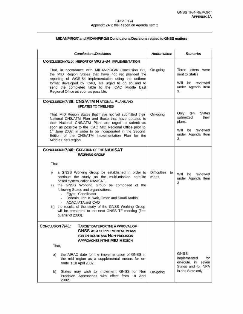
MIDANPIRG/7 and MIDANPIRG/8 Conclusions/Decisions related to GNSS matters
Conclusions/Decisions Action taken Remarks
CONCLUSION7/25: REPORT OF WGS-84 IMPLEMENTATION
That, in accordance with MIDANPIRG/6 Conclusion 6/1, the MID Region States that have not yet provided the reporting of WGS-84 implementation using the uniform format developed by ICAO, are urged to do so and to send the completed table to the ICAO Middle East Regional Office as soon as possible.
On-going
Three letters were sent to States Will be reviewed under Agenda Item 3.
CONCLUSION 7/39: CNS/ATM N ATIONAL PLANS AND UPDATES TO TIMELINES
That, MID Region States that have not yet submitted their National CNS/ATM Plan and those that have updates to their National CNS/ATM Plan, are urged to submit as soon as possible to the ICAO MID Regional Office prior to 1st June 2002, in order to be incorporated in the Second Edition of the CNS/ATM Implementation Plan for the Middle East Region.
On-going
Only ten States submitted their plans. Will be reviewed under Agenda Item 3.
CONCLUSION 7/40: CREATION OF THE NAVISAT WORKING GROUP
That, i) a GNSS Working Group be established in order to
continue the study on the multi-mission satellite based system, called NAVISAT.
ii) the GNSS Working Group be composed of the following States and organizations:
- Egypt: Coordinator - Bahrain, Iran, Kuwait, Oman and Saudi Arabia - ACAC, IATA and ICAO
iii) the results of the study of the GNSS Working Group will be presented to the next GNSS TF meeting (first quarter of 2003).
Difficulties to meet
Will be reviewed under Agenda Item 3
CONCLUSION 7/41: TARGET DATE FOR THE APPROVAL OF GNSS AS A SUPPLEMENTAL MEANS FOR EN-ROUTE AND NON-PRECISION APPROACHES IN THE MID REGION
That, a) the AIRAC date for the implementation of GNSS in
the mid region as a supplemental means for en-route is 18 April 2002.
b) States may wish to implement GNSS for Non
Precision Approaches with effect from 18 April 2002.
On-going
GNSS implemented for en-route in seven States and for NPA in one State only.
GNSS TF/4-REPORT APPENDIX 2A
2A-2
Conclusions/Decisions Action taken Remarks
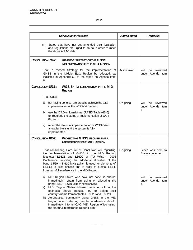
c) States that have not yet amended their legislation
and regulations are urged to do so in order to meet the above AIRAC date.
CONCLUSION 7/42: REVISED STRATEGY OF THE GNSS IMPLEMENTATION IN THE MID REGION
That, a revised Strategy for the implementation of GNSS in the Middle East Region be adopted, as indicated in Appendix 6E to the report on Agenda Item 6.
Action taken
Will be reviewed under Agenda Item 3
CONCLUSION 8/36: WGS-84 IMPLEMENTATION IN THE MID REGION
That, States
a) not having done so, are urged to achieve the total implementation of the WGS-84 System;
b) use the ICAO uniform format (FASID Table AIS-5) for reporting the status of implementation of WGS-84; and
c) report the status of implementation of WGS-84 on a regular basis until the system is fully implemented.
On-going
Will be reviewed under Agenda Item 3
CONCLUSION 8/52: PROTECTING GNSS FROM HARMFUL INTERFERENCE IN THE MID REGION
That considering, Para. (c) of Conclusion 7/8, regarding the Implementation of GNSS in the MID Region, footnotes 5.362B and 5.362C of ITU WRC – 2003 Conference, reporting the additional allocation of the band 1 559 – 1 610 MHz (which is used for elements of GNSS) to fixed service and in order to protect GNSS from harmful interference in the MID Region: i) MID Region States who have not done so should
immediately refrain from using or allocating the band 1 559 – 1 610 MHz to fixed service.
ii) MID Region States whose name is still in the footnotes should request ITU to delete their country’s name from footnotes 5.362B and 5.362C.
iii) Aeronautical community using GNSS in the MID Region when detecting harmful interference should immediately inform ICAO MID Region office using the Harmful Interference Report Form.
On-going
Letter was sent to States concerned. Will be reviewed under Agenda Item 4.
------------
GNSS TF/4-REPORT 3-1
GNSS TF/4
Report on Agenda Item 3
REPORT ON AGENDA ITEM 3: GNSS IMPLEMENTATION 3.1 Under this Agenda Item, the GNSS TF Action Group presented a progress report on the activities of the Action Group, especially with regard to the analysis and study of the MIDAN Demonstration results to validate APV1 and APV2 capabilities of the EGNOS system in the MID Region. The ESTB measured performance during the test campaign showed that the performance level up to APV2 requirements could be met in the tested part of the region. 3.2 In order to support the tes t bed during the dynamic trials at Cairo airport, the data collected from the RIMS installed in Bahrain, Cairo and Jeddah airports were processed. Additional performance indications of the static data provided by the Bahrain and Jeddah RIMS will be processed and their results reported by the end of July 2004. In this regard, ENAV in coordination with Galileo Joint Undertaking is available to support any future activity aiming at the implementation of a test bed over the Region. 3.3 Confirming the above information, ENAV (Italy) made a presentation describing the overall MIDAN activities and technical results achieved during the test campaign. However, it was pointed out that the results of the demo should take into account the limited ground infrastructure and the period of time. The overall MIDAN activities and results are in Appendix 3A to the report on Agenda Item 3. 3.4 The results of the demo also showed that the extension of the EGNOS architecture is technically feasible in the MID Region provided that additional reference stations are installed in adequate sites. In this case, the adequate system engineering studies should be carried-out in order to define the final architecture to meet the operational requirements (APV1 or APV2). 3.5 Galileo Joint Undertaking provided the meeting with the latest developments of EGNOS and Galileo projects that will start their initial operations in 2004 and 2008, respectively. The meeting noted that, though the GEO satellites cover the MID Region, the current EGNOS service is still limited to the core States of Europe. 3.6 The meeting noted with interest that the scope of cooperation between MID Region and Europe comprises several activities (programmatic and system level activities and introduction of operational services in aviation) that could help the States to facilitate the implementation of the GNSS in the Region. 3.7 Taking into account the limited coverage area of EGNOS service within the Middle East Region, the meeting was of the view that in the framework of the cost-benefit analysis, European Space Agency, in coordination with Galileo Joint Undertaking, carries out system engineering studies to define adequate architecture scenarios and its cost estimation, so as to satisfy APV 1 and APV 2 requirements in the Region. 3.8 Therefore, the meeting formulated the following Draft Conclusion: DRAFT CONCLUSION 4/1: FURTHER TEST ACTIVITIES AND STUDIES OF EGNOS IN
THE MID REGION That,
a) EGNOS test bed based on the ENAV experience during the MIDAN activities be continued until adequate data representative of the region be available;
GNSS TF/4 -REPORT 3-2
GNSS TF/4
Report on Agenda Item 3
b) the feasibility of using additional Ranging Integrity Monitoring Systems (RIMS) for achieving APV1 and APV2 requirements and a proposal for time scale be evaluated by Galileo Joint Undertaking;
c) to support the regional cost-benefit analysis, European Space Agency
(ESA), defines the EGNOS architecture scenarios on the number/location of RIMS required for achieving APV 1 and APV 2 requirements throughout the Region.
3.9 The meeting noted with interest the proposal from US Trade and Development Agency (USTDA) for feasibility studies of the possibility of implementing a GNSS/SBAS in the Middle East Region. This new test bed should be considered as one of the options for GNSS augmentation scenario in the Region and as such should be supported by the States. In this regard, the meeting formulated the following Draft Conclusion: DRAFT CONCLUSION 4/2: WAAS D EMONSTRATION TEST BEDS That, the States of the MID Region be encouraged to participate in the study of
the WAAS demonstration test beds by providing facilities for the reference stations when required.
3.10 Innovative Solutions International (ISI) provided the meeting with the latest developments of WAAS. This augmentation system that started operating in July 2003 gave a crucial step on the way to highly accurate satellite-based augmentation, enabling guaranteed position accuracy for horizontal and vertical requirements. 3.11 Noting that there was no ICAO guidance material available for the approval procedures, the meeting emphasized that the development and implementation of procedures for airworthiness and operational approval of GNSS were State’s responsibility. 3.12 The meeting was also informed that the MID Region might seek the assistance of the US Trade Development Agency (USTDA) with a view to study the implementation of the GNSS procedures in the Region based on the GPS constellation. 3.13 Considering the importance of Non Precision Approaches (NPA) within the whole GNSS implementation process, ISI will propose a cos t effective solution to co-design the procedures with the MID States. 3.14 The meeting was also presented with an overview of the recent developments of the different ground based augmentation systems (GRAS, LAAS etc.). The use of the Ground Regional Augmentation System (GRAS) could be of interest to the Region, as a potential more practical means of distributing augmentation data where the dedicated GEO satellites are not available or affordable. In this regard, Saudi Arabia and ICAO Office are requested to get more information on this new augmentation system. 3.15 As regards the NAVISAT project, which could be considered as one of the space communications segment options to support the implementation of GNSS in the Region, the meeting was of the view that the NAVISAT Working Group had not yet accomplished its task. Consequently, the members of the related working group were urged to coordinate actions so as to provide the GNSS TF with the results of NAVISAT study, taking into account the IATA’s comments and remarks.
GNSS TF/4-REPORT 3-3
GNSS TF/4
Report on Agenda Item 3
3.16 Based on the above, the meeting agreed to the following Draft Conclusion: DRAFT CONCLUSION 4/3: COST-BENEFIT CONSIDERATION FOR AUGMENTATION
SYSTEMS That,
a) no commitment be made on the augmentation systems to be used
until all other options and implementation trends with associated cost benefit analyses are fully considered; and
b) implementation strategy to be considered with user requirements, implementation trends/options endorsed in adjacent regions in accordance with the operational concept and planning principles of the global air navigation plan for CNS/ATM systems.
3.17 Reviewing the GNSS activities, the meeting made some amendments (inclusion of maps on communication and navigation means) in the Package 1 of the document called “Improvement of Navigation Systems in the MID Region” which is in Appendix 3B to the report on Agenda Item 3. This document could be complementary to the Strategy of the GNSS implementation in the Region and as such should be updated on a regular basis. Then, the meeting urged the GNSS Task Force Action Group to achieve the development of the Package 2 related to the Implementation of requirements. 3.18 In the light of the above, the meeting reviewed the Revised Strategy for the Implementation of GNSS capabilities in the MID Region and decided to amend it as indicated in Appendix 3C to the report on Agenda Item 3.
---------------

ENAV S.p.A.M I D A ND E M O
PROJECT: MIDAN
DOCUMENT TITLE: MIDAN DEMO REPORT
TOTAL PAGES: 42
Function Name (Company)
Author(s): Stefano Lagrasta, Filippo Rodriguez, Giovanni Valentini (Telespazio)
Checked by: Stefano Lagrasta (Telespazio), RenatoPerago (ENAV)
Project Manager: Renato Perago (ENAV)
Program Manager: Giovanni Del Duca (ENAV)
Classification: N.A. Name (Function/Company)
Authorised by:
Approved by: Fabio Milioni (ENAV)
ENAV S.p.A. MIDAN DEMO
Doc. No: GNSS-MID-TN-A01 Issue: 2.0 Rev: 1 Date: April 30th , 2004
Page: 2 of 42
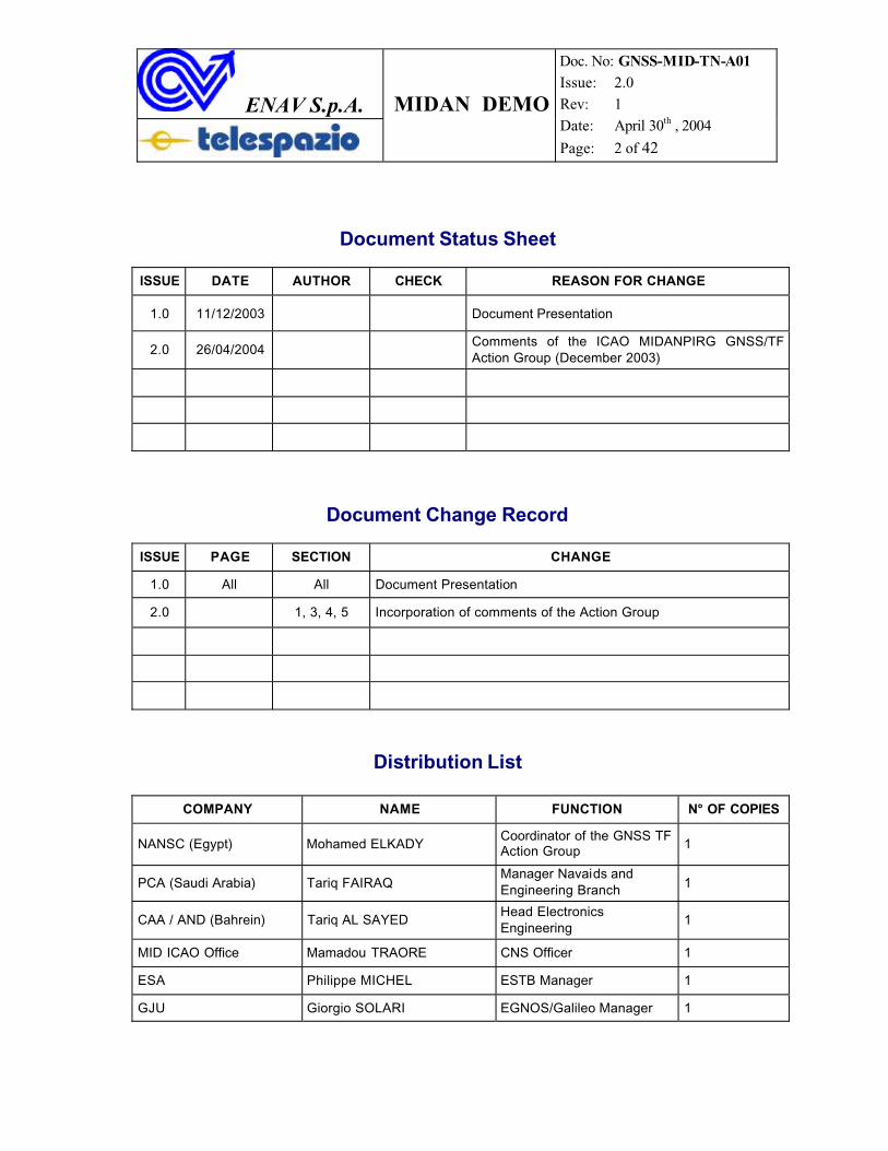
Document Status Sheet
ISSUE DATE AUTHOR CHECK REASON FOR CHANGE
1.0 11/12/2003 Document Presentation
2.0 26/04/2004Comments of the ICAO MIDANPIRG GNSS/TFAction Group (December 2003)
Document Change Record
ISSUE PAGE SECTION CHANGE
1.0 All All Document Presentation
2.0 1, 3, 4, 5 Incorporation of comments of the Action Group
Distribution List
COMPANY NAME FUNCTION N° OF COPIES
NANSC (Egypt) Mohamed ELKADYCoordinator of the GNSS TF Action Group 1
PCA (Saudi Arabia) Tariq FAIRAQManager Navaids and Engineering Branch 1
CAA / AND (Bahrein) Tariq AL SAYEDHead Electronics Engineering
1
MID ICAO Office Mamadou TRAORE CNS Officer 1
ESA Philippe MICHEL ESTB Manager 1
GJU Giorgio SOLARI EGNOS/Galileo Manager 1
ENAV S.p.A. MIDAN DEMO
Doc. No: GNSS-MID-TN-A01 Issue: 2.0 Rev: 1 Date: April 30th , 2004
Page: 3 of 42
TABLE OF CONTENTS
1 INTRODUCTION ............................................................................................................ 5
1.1 PURPOSE AND SCOPE................................................................................................... 5THIS REPORT DEALS WITH THE PROCESSES CARRIED OUT BY ENAV AND TELESPAZIO AND
PRESENTS THE MAIN OUTCOMES. ............................................................................................. 51.2 EXECUTIVE SUMMARY ................................................................................................ 61.3 DOCUMENT OVERVIEW ............................................................................................... 61.4 THE SBAS CONCEPT................................................................................................... 71.5 EUROPEAN GEOSTATIONARY NAVIGATION OVERLAY SYSTEM (EGNOS) .................. 91.6 THE EGNOS SYSTEM TEST BED (ESTB).................................................................... 91.7 THE MEDITERRANEAN TEST BED (MTB).................................................................. 11
2 PRE-FLIGHT ACTIVITIES......................................................................................... 12
2.1 TEST-BED ARCHITECTURE ........................................................................................ 122.2 SITE SURVEYS ........................................................................................................... 142.3 TEST-BED RECONFIGURATION FOR THE DEMO.......................................................... 152.4 USER TERMINAL........................................................................................................ 16
3 IN-FLIGHT ACTIVITIES ............................................................................................ 17
3.1 FLIGHT SESSIONS SCHEDULE..................................................................................... 173.2 DATA SET.................................................................................................................. 18
3.2.1 Flight Data Set ................................................................................................. 183.2.1.1 Flights nr. 101 and 102 ................................................................................. 183.2.1.2 Flight Session # 1 (Data Set nr. 103)............................................................ 193.2.1.3 Flight Session # 2 (Data Set nr. 105)............................................................ 193.2.1.4 Session # 3 (Data Set nr. 106) ...................................................................... 193.2.1.5 Session # 4 (Data Set nr. 108) ...................................................................... 203.2.1.6 Flight nr. 109 ................................................................................................ 21
3.2.2 RIMS Data Set .................................................................................................. 21
4 POST-FLIGHT ANALYSES ........................................................................................ 22
4.1 METHODOLOGY......................................................................................................... 224.2 RIMS AND FLIGHT UP ROW DATA PRE-PROCESSING............................................... 22
4.2.1 Use of ITT COTS .............................................................................................. 224.2.2 SW Development for Flight Data Files Pre-processing ................................... 22
4.3 FINAL AVAILABLE DATA SET ..................................................................................... 224.4 “TRUE” PATH CALCULATION .................................................................................... 23
5 TEST-BED PERFORMANCE...................................................................................... 25
5.1 COMPARING UP NAVIGATION DATA AND TRUE PATH .............................................. 255.2 FLIGHT SESSION # 2 (DATA SET NR. 105) .................................................................. 26
5.2.1 Offset between GPS and SBAS position ........................................................... 265.2.2 True offset evaluation: SBAS position errors ................................................... 26
ENAV S.p.A. MIDAN DEMO
Doc. No: GNSS-MID-TN-A01 Issue: 2.0 Rev: 1 Date: April 30th , 2004
Page: 4 of 42
5.2.3 Consistency of SBAS Protection Levels against “true” error.......................... 275.3 FLIGHT SESSION # 3 (DATA SET NR. 106) .................................................................. 27
5.3.1 Offset between GPS and SBAS position ........................................................... 275.3.2 True offset evaluation: SBAS position errors ................................................... 285.3.3 Consistency of SBAS Protection Levels against “true” error.......................... 28
5.4 FLIGHT SESSION # 4 (DATA SET NR. 108) .................................................................. 295.4.1 Offset between GPS and SBAS position ........................................................... 295.4.2 True offset evaluation: SBAS position errors ................................................... 295.4.3 Consistency of SBAS Protection Levels against “true” position ..................... 30
5.5 FLIGHT SESSION # 1 (DATA SET 103) ........................................................................ 315.5.1 Offset between GPS and SBAS coordinates ..................................................... 315.5.2 True offset evaluation: SBAS error .................................................................. 315.5.3 Consistency of SBAS Protection Levels against “true” error.......................... 32
5.6 STANFORD DIAGRAMS............................................................................................... 335.6.1 Flight Session # 2 (Data set nr. 105)................................................................ 335.6.2 Flight Session #3 (Data set nr. 106)................................................................. 335.6.3 Flight Session # 4 (Data set nr. 108)................................................................ 34
5.7 THREE-DIMENSIONAL DIAGRAMS.............................................................................. 35
6 CONCLUSIONS............................................................................................................. 37
7 ACKNOWLEDGEMENTS ........................................................................................... 38
8 BACKGROUND INFORMATION .............................................................................. 39
8.1 PERFORMANCE-RELATED CONCEPTS ......................................................................... 398.2 “STANFORD” DIAGRAMS........................................................................................... 408.3 REFERENCE DOCUMENTS .......................................................................................... 418.4 ACRONYMS................................................................................................................ 42
ENAV S.p.A. MIDAN DEMO
Doc. No: GNSS-MID-TN-A01 Issue: 2.0 Rev: 1 Date: April 30th , 2004
Page: 5 of 42
1 INTRODUCTION
1.1 Purpose and Scope
It is common knowledge that the implementation of SBAS services, compared to thosebased on the traditional navigational aids, is cost effective for the widespread exploitation of flight operations down to ICAO APV1 and APV2 performance requirements. This result is emphasized where the availability of existing navigation infrastructure is limited.
The MIDAN Demo is a joint initiative of: ENAV, ESA, European Commission and Telespazio, endorsed by the ICAO Office of the MID Region. The general purpose of the MIDANdemonstration is to verify and demonstrate the feasibility of extending the provision of EGNOS services from the original service area (ECAC) to the ICAO MID Region. To this end, the following objectives were established:
1. to select the test airspace, that is within a circle of 25 NM around the Cairo International Airport;
2. to extend the ESTB (EGNOS System Test Bed)/MTB (Mediterranean Test Bed) architecture with three additional portable Ranging and Integrity Monitor Station(RIMS), to allow sufficient data collection and processing;
3. to reconfigure the ESTB computing platform, to generate the SBAS augmentation messages for the new system;
4. to collect GPS static and in-flight data, augmented by ESTB/MTB, in the tested airspace;
5. to carry out a statistical assessment of the performance against ICAO performance requirements up to APV2;
6. to provide evidence that EGNOS is able to meet up to APV2 requirements over the Region.
In order to achieve the above targets, essential logistic and technical support was provided by the Air Navigation Services Providers/Civil Aviation Administrations of the following States, which hosted the three portable RIMS:
� Egypt (National Air Navigation Services Company - NANSC);� Bahrein (Civil Aviation Authorities - CAA);� Saudi Arabia (Presidency of Civil Aviation - PCA).
Static and in-flight measurements were carried out using equipment and aircraft of ENAV S.p.A., and the support of personnel of Telespazio S.p.A.
For the sake of the completeness, two analogous methods have been adopted to carry out the data processing. According to the Program arrangements, ENAV has taken theleadership on this activity, and ESA has provided relevant complementary results [ 1 ].
This Report deals with the processes carried out by ENAV and Telespazio and presents the main outcomes.
ENAV S.p.A. MIDAN DEMO
Doc. No: GNSS-MID-TN-A01 Issue: 2.0 Rev: 1 Date: April 30th , 2004
Page: 6 of 42
1.2 Executive Summary
This document is the overall Report of the activities performed and results achieved duringthe MIDAN Demo campaign.
The in-flight data collection was carried out both during the transfer flightsRome/Cairo/Rome, which occurred the 7th and 10th October 2002, and during the four flight technical sessions, which occurred the 8th and 9th October 2002 within the Cairo airport ATZ (Air Traffic Zone). Throughout all the flights, GPS/SBAS data was collected.
In particular, each of the four technical sessions cons isted of a sequence of ILS Cat Iapproaches to the runway 05R, followed by a full stop landing. In total, more than twenty approaches were performed.
The post-flight analyses have focused mainly on the four flight technical sessions, together with the relevant data recorded by the RIMS installed in Cairo. Their results are satisfactory and in line with the expectations in terms of system performance. In fact, within the Cairo ATZ the MIDAN test bed met the ICAO horizontal and vertical requirements for APV 1 in all the cases, and APV 2 vertical requirements during most of them.
However, it is pointed out that complete considerations of the results achieved shall take into account:
• the minimal ground infrastructure of the test-bed used;• the particular/stressed manoeuvres (i.e. circular patterns or bank angles up to 60°)
performed by the flight inspection airplane;• the use of experimental hardware and software;• the handing of data having different formats.
1.3 Document Overview
The present document has the following structure:
• Section 1: Summary, Introduction, SBAS Concept and Systems;• Section 2: Pre-flight Activities and MIDAN Test-bed Architecture;• Section 3: In-flight Activities;• Section 4: Post-flight Activities;• Section 5: Test-bed Performance;• Section 6: Conclusions;• Section 7: Acknowledgements;• Section 7: Background Information.
ENAV S.p.A. MIDAN DEMO
Doc. No: GNSS-MID-TN-A01 Issue: 2.0 Rev: 1 Date: April 30th , 2004
Page: 7 of 42
1.4 The SBAS Concept
A “Satellite-Based Augmentation System” (SBAS) is compliant with ICAO SARPs (Annex 10) and provides the GNSS user with additional information, broadcast via geostationarysatellites, which is not actually provided by the orbiting GNSS constellation. SBASimplementations are being deployed or commissioned in Europe (EGNOS), US (WAAS) and Japan (MSAS).
The SBAS signal in space (SIS) broadcasts the following “augmentation” data messages:
• Wide Area Differential (WAD);• GNSS Integrity Channel (GIC).
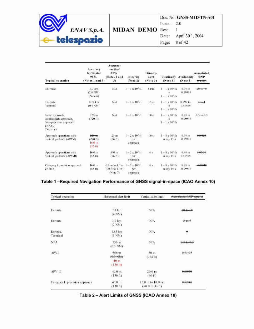
The WAD information aims at improving the user positioning accuracy within the SARPs prescribed tolerance (see Table 1). In a sketched view, through the WAD data messages the user can compute and apply corrective information to GPS raw measurements:
- “Fast corrections”, to compensate for GPS satellite clock errors;- “Slow term corrections”, to estimate and reduce the impact of clock, ionosphere and
ephemeris related perturbations.
The GIC is a prerequisite for safety-of-life users, providing the adequate level of confidence about the quality of service. In fact, it enables the user to:
- select only GPS signals which have been addressed to be “safe” by the SBAS, within a time-to-alarm as low as 6 (six) seconds;
- estimate the SBAS position (both horizontal and vertical) “residual error”, that is after the application of the WAD corrections.
The real-time estimation of the SBAS “residual error”, is of primary interest for civil aviation. In fact, the system overall position accuracy does not provide any guarantee about its integrity during each specific flight operation. In addition, the civil aviator needs: to estimate the horizontal and vertical positioning errors – called “Protection Levels” (HPL and VPL), and to compare them to the SARPs prescribed tolerance, (Horizontal and Vertical Alert Limits, HAL and VAL, see Table 2) at each second.
The Tables 1 and 2 exhibit the performance requirements of GNSS, including the lastamendment of the ICAO Annex 10 (red types).
SBAS performance cover the operations from en-route down to APV II (or APV I, according to the SBAS infrastructure).
ENAV S.p.A. MIDAN DEMO
Doc. No: GNSS-MID-TN-A01 Issue: 2.0 Rev: 1 Date: April 30th , 2004
Page: 8 of 42
Table 1 –Required Navigation Performance of GNSS signal-in-space (ICAO Annex 10)
Table 2 – Alert Limits of GNSS (ICAO Annex 10)
ENAV S.p.A. MIDAN DEMO
Doc. No: GNSS-MID-TN-A01 Issue: 2.0 Rev: 1 Date: April 30th , 2004
Page: 9 of 42
1.5 European Geostationary Navigation Overlay System (EGNOS)
EGNOS is the European SBAS realization for civil and commercial applications of: aviation, maritime and land users.
EGNOS services, which augment GPS (and GLONASS), are broadcast through three GEO satellites (INMARSAT-III AOR-E, INMARSAT-III IOR and the ESA ARTEMIS), which cover the European Civil Aviation Conference (ECAC) service area. EGNOS services are thefollowing:
1. GEO Ranging (R-GEO): GPS-like signals transmitted, increasing the number of ranging sources available to the users;
2. Wide Area Differential (WAD): differential corrections increasing the GPS (and GLONASS) pseudorange accuracy, supporting flight operationa down to APV II;
3. GNSS Integrity Channel (GIC): integrity information down to APV II performance.
According to SBAS SARPs, the EGNOS information is fitted in several different “messages”, each being identified by a numeric ID, from 0 to 63, also called up as “message type #”. Any message is 250 bit long (212 data bits, plus an error CRC) and is transmitted every second.
As an example, for the computation of the “fast corrections”, the following message types are necessary: type 1, one of the types 2,3,4,5, and type 7.
1.6 The EGNOS System Test Bed (ESTB)
ESTB is a real-time full-scale prototype of EGNOS providing, since February 2000, a continuous experimental GPS augmentation service over Europe. The ESTB main objectives are:
• to support EGNOS design (algorithms design benefits from ESTB experience in design and usage);
• to allow verification and demonstration of possible EGNOS applications to users;• to analyse future EGNOS upgrades;• to allow EGNOS experimentation and design improvement process.
By the combination of GPS+ESTB observations, European users can determine the position with an error less than 3 meters (horizontal) and 5 meters (vertical), 95 percent of the time.
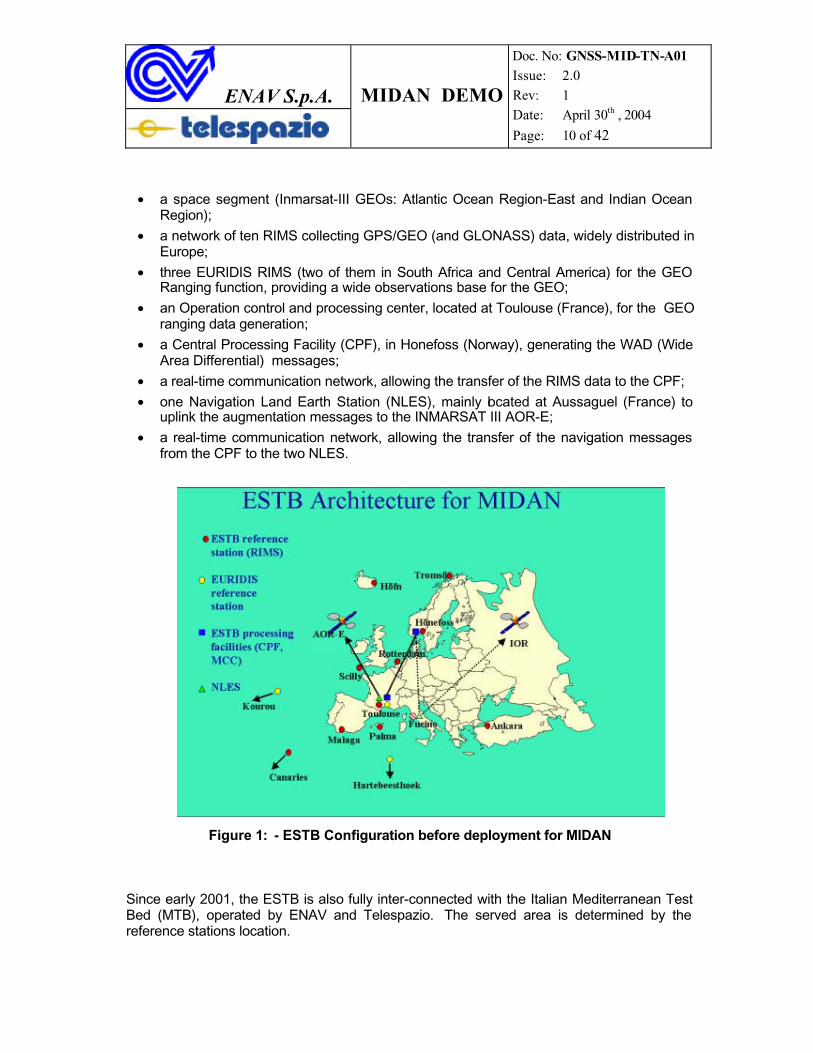
The ESTB development has been based upon a number of pre-existing systems, such as the SATREF™ system from NMA (Norwegian Mapping Authority) and the EURIDIS ranging system from the French Space Agency (CNES). Before the customization for the MIDAN Demo, ESTB consisted of the following components (Figure 1):
ENAV S.p.A. MIDAN DEMO
Doc. No: GNSS-MID-TN-A01 Issue: 2.0 Rev: 1 Date: April 30th , 2004
Page: 10 of 42
• a space segment (Inmarsat-III GEOs: Atlantic Ocean Region-East and Indian Ocean Region);
• a network of ten RIMS collecting GPS/GEO (and GLONASS) data, widely distributed in Europe;
• three EURIDIS RIMS (two of them in South Africa and Central America) for the GEO Ranging function, providing a wide observations base for the GEO;
• an Operation control and processing center, located at Toulouse (France), for the GEO ranging data generation;
• a Central Processing Facility (CPF), in Honefoss (Norway), generating the WAD (Wide Area Differential) messages;
• a real-time communication network, allowing the transfer of the RIMS data to the CPF;
• one Navigation Land Earth Station (NLES), mainly located at Aussaguel (France) to uplink the augmentation messages to the INMARSAT III AOR-E;
• a real-time communication network, allowing the transfer of the navigation messages from the CPF to the two NLES.
Figure 1: - ESTB Configuration before deployment for MIDAN
Since early 2001, the ESTB is also fully inter-connected with the Italian Mediterranean Test Bed (MTB), operated by ENAV and Telespazio. The served area is determined by the reference stations location.
ENAV S.p.A. MIDAN DEMO
Doc. No: GNSS-MID-TN-A01 Issue: 2.0 Rev: 1 Date: April 30th , 2004
Page: 11 of 42
1.7 The Mediterranean Test Bed (MTB)
MTB system is an SBAS test-bed, whose core components are hosted at Telespazio "Piero Fanti" Space Centre premises (Fucino, Italy).
MTB includes a network of remote TRS (Test Reference Stations) for collecting GPSmeasurements and a master facility (Terrestrial Monitoring System, TMS) for computing the SBAS navigation message content. Even if MTB consists of a minimal infrastructure, it has the capability of carrying GPS integrity and differential corrections information.
Operational since 1997, MTB was developed under a co-operative agreement with the U.S. Federal Aviation Administration (FAA) and ENAV, through Telespazio, for test andverification of the WAAS concept, providing the broadcasting of a SBAS navigation signal through INMARSAT (IOR) satellite according to the RTCA MOPS specification [ 3 ].
Using MTB and the US National Satellite Test Bed (NSTB), the first SBAS flight trials in Europe were performed in 1997 [ 4 ]. Since then, MTB was upgraded towards theinteroperation with ESTB and expansion of processing capability [ 5 ].
ESTB-MTB interface was firstly validated in February 2001, achieving a full integration. In particular, during ESTB operations prior to the MIDAN Demo, MTB performed the following functions:
• to interface and process data of ESTB Remote Integrity Monitoring Stations (RIMS);
• to convert the native MTB TRS outputs into the RIMS format;
• to generate and uplink a GIC/WAD ESTB Signal In Space to the INMARSAT III IOR, based upon navigation message computed at ESTB Honefoss center (alternatively to the native capability of TMS);
• to supply both TRS and RIMS measurements for extending ESTB system coverage beyond the Mediterranean basin.
ENAV S.p.A. MIDAN DEMO
Doc. No: GNSS-MID-TN-A01 Issue: 2.0 Rev: 1 Date: April 30th , 2004
Page: 12 of 42
2 PRE-FLIGHT ACTIVITIES
2.1 Test-Bed Architecture
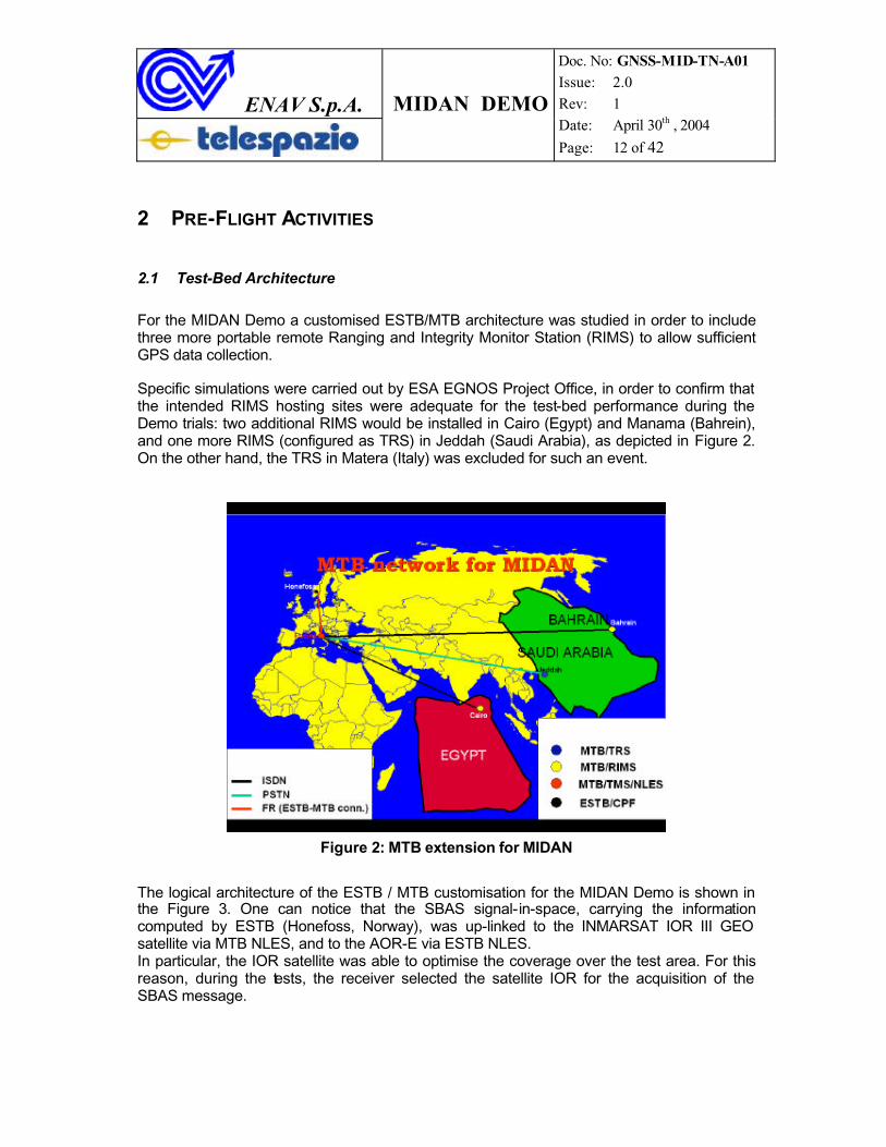
For the MIDAN Demo a customised ESTB/MTB architecture was studied in order to include three more portable remote Ranging and Integrity Monitor Station (RIMS) to allow sufficient GPS data collection.
Specific simulations were carried out by ESA EGNOS Project Office, in order to confirm that the intended RIMS hosting sites were adequate for the test-bed performance during the Demo trials: two additional RIMS would be installed in Cairo (Egypt) and Manama (Bahrein), and one more RIMS (configured as TRS) in Jeddah (Saudi Arabia), as depicted in Figure 2.On the other hand, the TRS in Matera (Italy) was excluded for such an event.
Figure 2: MTB extension for MIDAN
The logical architecture of the ESTB / MTB customisation for the MIDAN Demo is shown in the Figure 3. One can notice that the SBAS signal-in-space, carrying the informationcomputed by ESTB (Honefoss, Norway), was up-linked to the INMARSAT IOR III GEO satellite via MTB NLES, and to the AOR-E via ESTB NLES.In particular, the IOR satellite was able to optimise the coverage over the test area. For this reason, during the tests, the receiver selected the satellite IOR for the acquisition of the SBAS message.
ENAV S.p.A. MIDAN DEMO
Doc. No: GNSS-MID-TN-A01 Issue: 2.0 Rev: 1 Date: April 30th , 2004
Page: 13 of 42
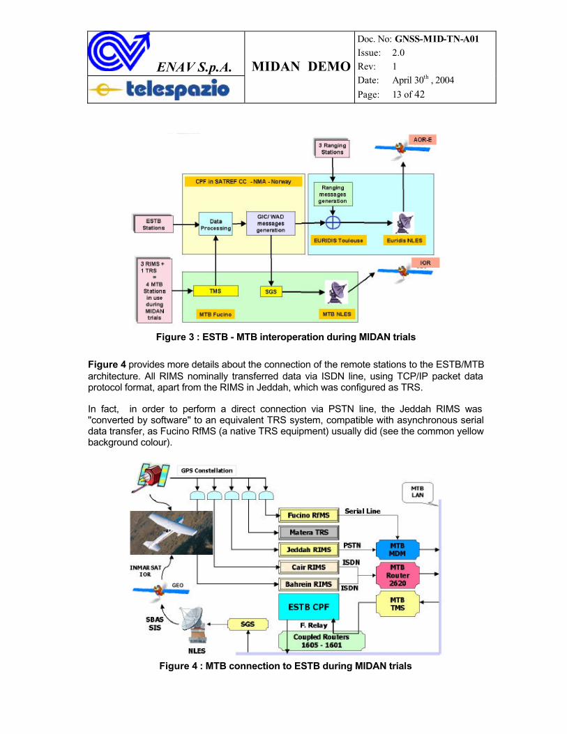
Figure 3 : ESTB - MTB interoperation during MIDAN trials
Figure 4 provides more details about the connection of the remote stations to the ESTB/MTB architecture. All RIMS nominally transferred data via ISDN line, using TCP/IP packet data protocol format, apart from the RIMS in Jeddah, which was configured as TRS.
In fact, in order to perform a direct connection via PSTN line, the Jeddah RIMS was "converted by software" to an equivalent TRS system, compatible with asynchronous serial data transfer, as Fucino RfMS (a native TRS equipment) usually did (see the common yellow background colour).
Figure 4 : MTB connection to ESTB during MIDAN trials
ENAV S.p.A. MIDAN DEMO
Doc. No: GNSS-MID-TN-A01 Issue: 2.0 Rev: 1 Date: April 30th , 2004
Page: 14 of 42
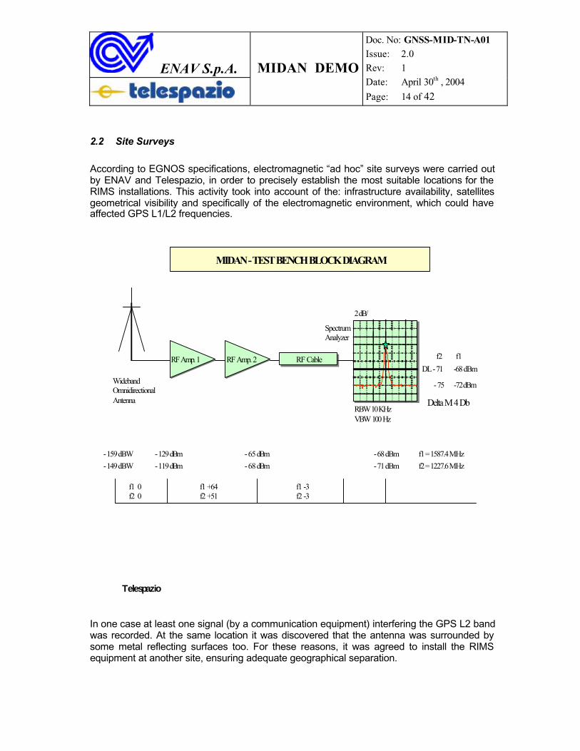
2.2 Site Surveys
According to EGNOS specifications, electromagnetic “ad hoc” site surveys were carried out by ENAV and Telespazio, in order to precisely establish the most suitable locations for the RIMS installations. This activity took into account of the: infrastructure availability, satellites geometrical visibility and specifically of the electromagnetic environment, which could have affected GPS L1/L2 frequencies.
RF CableRF Cable
MIDAN - TEST BENCH BLOCK DIAGRAM
RF Amp. 2RF Amp. 2
SpectrumAnalyzer
f1 -3f2 -3
- 75 -72 dBm
- 71 dBm- 68 dBm- 119 dBm- 149 dBW
DL - 71 -68 dBm
2 dB/
f2 = 1227.6 MHz
- 68 dBm- 65 dBm- 129 dBm- 159 dBW f1 = 1587.4 MHz
Telespazio
RBW 10 KHzVBW 100 Hz
WidebandOmnidirectionalAntenna
RF Amp. 1 RF Amp. 1
f1 +64f2 +51
f1 0f2 0
f2 f1
Delta M 4 Db
In one case at least one signal (by a communication equipment) interfering the GPS L2 band was recorded. At the same location it was discovered that the antenna was surrounded by some metal reflecting surfaces too. For these reasons, it was agreed to install the RIMS equipment at another site, ensuring adequate geographical separation.
ENAV S.p.A. MIDAN DEMO
Doc. No: GNSS-MID-TN-A01 Issue: 2.0 Rev: 1 Date: April 30th , 2004
Page: 15 of 42
2.3 Test-Bed Reconfiguration for the Demo
As soon as all the remote RIMS were installed, they were connected to the test-bed sending the Central Processing Facility (CPF) GPS pseudorange observations on a continuous basis. First of all, this process allowed to determine the very precise position of each RIMS antenna, referred to WGS84 datum.
The following RIMS positions were determined:
Longitude (East) Latitude (North) Alt (m)
Cairo 31° 23' 18.9143644819" 30° 07' 6.0135398593" 110.77555
Manama 50° 38’ 34.3416780625” E 26° 15’ 41.7517976130“ -16.77841
Jeddah 39° 8’ 45.8932392328” E 21° 39’ 57.3774016882” N 15.60401
Table 3 – WGS 84 coordinates of RIMS antennas
Following the fine positioning of the RIMS, their data were accepted into the ESTB/MTB navigation solution and broadcast as well. This allowed the verification of performances and the tuning of the re-configured system, according to a re-iterative process.
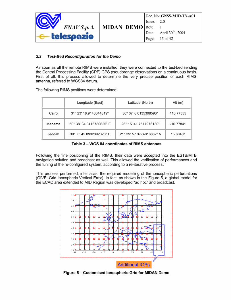
This process performed, inter alias, the required modelling of the ionospheric perturbations (GIVE: Grid Ionospheric Vertical Error). In fact, as shown in the Figure 5, a global model for the ECAC area extended to MID Region was developed “ad hoc” and broadcast.
- 4 0 - 3 0 - 2 0 - 1 0 0 1 0 2 0 3 0 4 0 5 02 5
3 0
3 5
4 0
4 5
5 0
5 5
6 0
6 5
7 0
7 5
Additional IGPsAdditional IGPs
Figure 5 – Customised Ionospheric Grid for MIDAN Demo
ENAV S.p.A. MIDAN DEMO
Doc. No: GNSS-MID-TN-A01 Issue: 2.0 Rev: 1 Date: April 30th , 2004
Page: 16 of 42
2.4 User Terminal
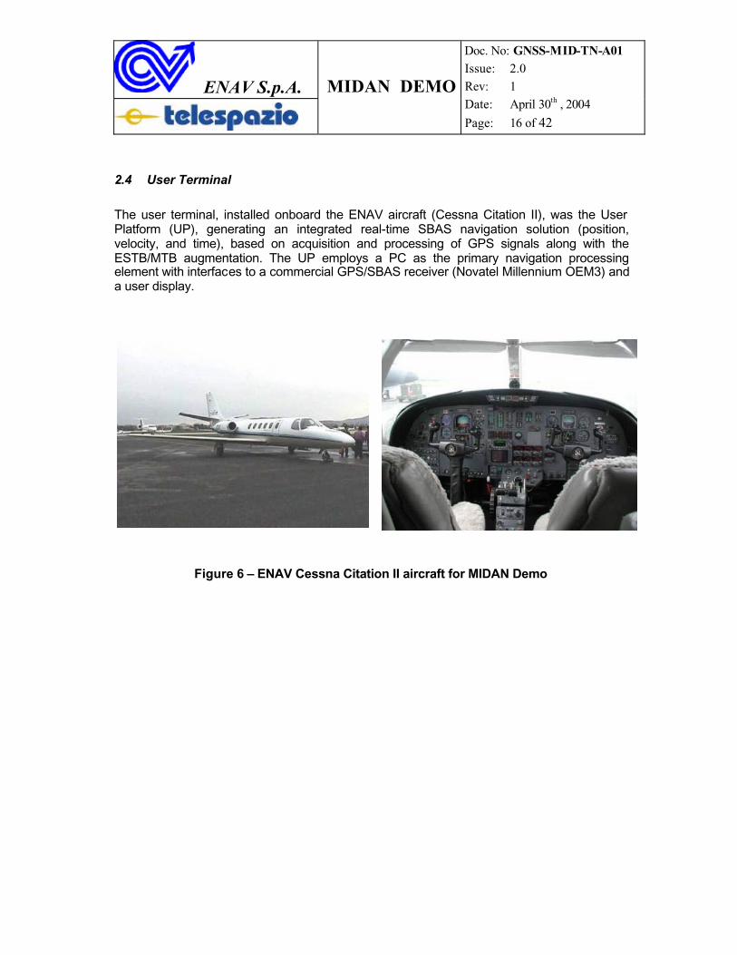
The user terminal, installed onboard the ENAV aircraft (Cessna Citation II), was the User Platform (UP), generating an integrated real-time SBAS navigation solution (position,velocity, and time), based on acquisition and processing of GPS signals along with theESTB/MTB augmentation. The UP employs a PC as the primary navigation processingelement with interfaces to a commercial GPS/SBAS receiver (Novatel Millennium OEM3) and a user display.
Figure 6 – ENAV Cessna Citation II aircraft for MIDAN Demo
ENAV S.p.A. MIDAN DEMO
Doc. No: GNSS-MID-TN-A01 Issue: 2.0 Rev: 1 Date: April 30th , 2004
Page: 17 of 42
3 IN-FLIGHT ACTIVITIES
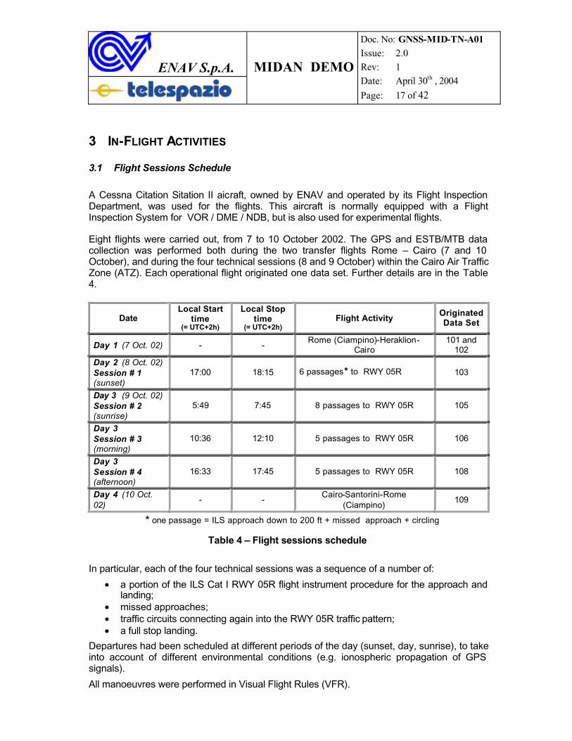
3.1 Flight Sessions Schedule
A Cessna Citation Sitation II aicraft, owned by ENAV and operated by its Flight Inspection Department, was used for the flights. This aircraft is normally equipped with a FlightInspection System for VOR / DME / NDB, but is also used for experimental flights.
Eight flights were carried out, from 7 to 10 October 2002. The GPS and ESTB/MTB data collection was performed both during the two transfer flights Rome – Cairo (7 and 10 October), and during the four technical sessions (8 and 9 October) within the Cairo Air Traffic Zone (ATZ). Each operational flight originated one data set. Further details are in the Table4.
DateLocal Start
time(= UTC+2h)
Local Stop time
(= UTC+2h)Flight Activity
OriginatedData Set
Day 1 (7 Oct. 02) - -Rome (Ciampino)-Heraklion-
Cairo101 and
102Day 2 (8 Oct. 02)Session # 1(sunset)
17:00 18:15 6 passages* to RWY 05R 103
Day 3 (9 Oct. 02)Session # 2(sunrise)
5:49 7:45 8 passages to RWY 05R 105
Day 3Session # 3(morning)
10:36 12:10 5 passages to RWY 05R 106
Day 3Session # 4(afternoon)
16:33 17:45 5 passages to RWY 05R 108
Day 4 (10 Oct. 02)
- -Cairo-Santorini-Rome
(Ciampino)109
* one passage = ILS approach down to 200 ft + missed approach + circling
Table 4 – Flight sessions schedule
In particular, each of the four technical sessions was a sequence of a number of:
• a portion of the ILS Cat I RWY 05R flight instrument procedure for the approach and landing;
• missed approaches;• traffic circuits connecting again into the RWY 05R traffic pattern;• a full stop landing.
Departures had been scheduled at different periods of the day (sunset, day, sunrise), to take into account of different environmental conditions (e.g. ionospheric propagation of GPS signals).
All manoeuvres were performed in Visual Flight Rules (VFR).
ENAV S.p.A. MIDAN DEMO
Doc. No: GNSS-MID-TN-A01 Issue: 2.0 Rev: 1 Date: April 30th , 2004
Page: 18 of 42
3.2 Data Set
Data can be distinguished into two main sets:
• flight data set;• RIMS data set.
3.2.1 Flight Data Set
As shown in Table 4, flight data is divided into seven different data series, each one referring to a specific flight.
It has to be remarked that the data through the onboard User Platform (UP) during the transfer flights (101, 102, 109) are not to be taken into account for ESTB/MTB performance characterisation. In fact, their flights occurred out of the coverage (25 NM) of the Differential GPS “truth” reference system installed at Cairo airport (see § 4.4).Instead, they could be considered for a “passive” monitoring of GPS signals and ESTB/MTBaugmentation, along with a demonstration of the navigation solution computation by the UP itself.
On the other hand, due to the electromagnetic effects, GNSS performance characterisation is more relevant for data collected at the lowest altitudes, that is during flight sessions from # 1 to # 4 (originated data sets: 103, 105, 106 and 108).
The next figures show the profiles all the flights, as derived from the outputs of the User Platform.
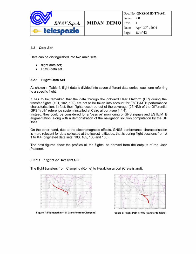
3.2.1.1 Flights nr. 101 and 102
The flight transfers from Ciampino (Rome) to Heraklion airport (Crete island).
Figure 7: Flight path nr 101 (transfer from Ciampino) Figure 8: Flight Path nr 102 (transfer to Cairo)
ENAV S.p.A. MIDAN DEMO
Doc. No: GNSS-MID-TN-A01 Issue: 2.0 Rev: 1 Date: April 30th , 2004
Page: 19 of 42
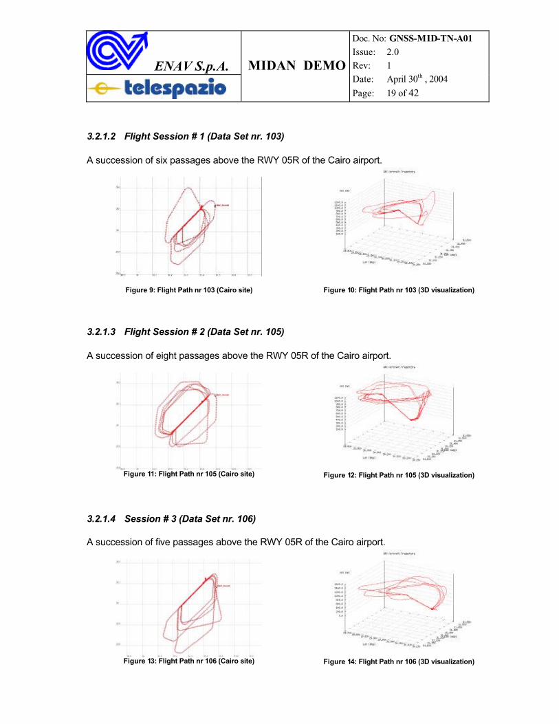
3.2.1.2 Flight Session # 1 (Data Set nr. 103)
A succession of six passages above the RWY 05R of the Cairo airport.
Figure 9: Flight Path nr 103 (Cairo site) Figure 10: Flight Path nr 103 (3D visualization)
3.2.1.3 Flight Session # 2 (Data Set nr. 105)
A succession of eight passages above the RWY 05R of the Cairo airport.
Figure 11: Flight Path nr 105 (Cairo site) Figure 12: Flight Path nr 105 (3D visualization)
3.2.1.4 Session # 3 (Data Set nr. 106)
A succession of five passages above the RWY 05R of the Cairo airport.
Figure 13: Flight Path nr 106 (Cairo site) Figure 14: Flight Path nr 106 (3D visualization)
ENAV S.p.A. MIDAN DEMO
Doc. No: GNSS-MID-TN-A01 Issue: 2.0 Rev: 1 Date: April 30th , 2004
Page: 20 of 42
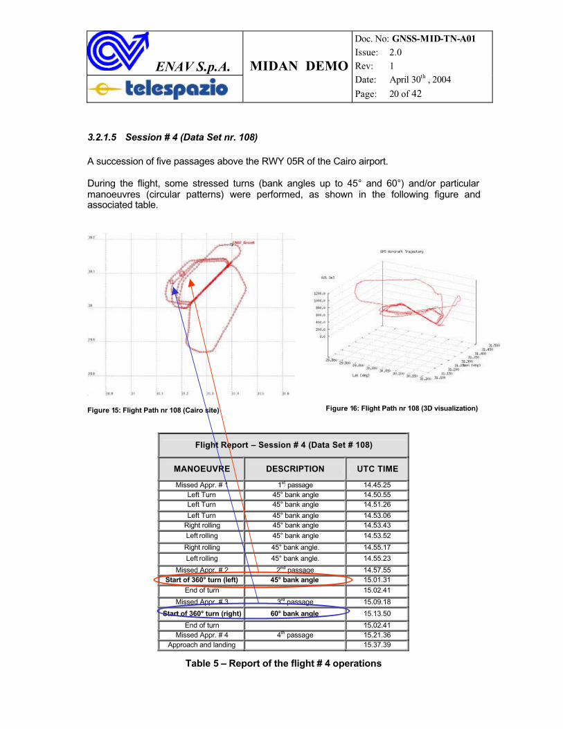
3.2.1.5 Session # 4 (Data Set nr. 108)
A succession of five passages above the RWY 05R of the Cairo airport.
During the flight, some stressed turns (bank angles up to 45° and 60°) and/or particular manoeuvres (circular patterns) were performed, as shown in the following figure andassociated table.
Figure 15: Flight Path nr 108 (Cairo site) Figure 16: Flight Path nr 108 (3D visualization)
Table 5 – Report of the flight # 4 operations
Flight Report – Session # 4 (Data Set # 108)
MANOEUVRE DESCRIPTION UTC TIME
Missed Appr. # 1 1st passage 14.45.25Left Turn 45° bank angle 14.50.55Left Turn 45° bank angle 14.51.26
Left Turn 45° bank angle 14.53.06Right rolling 45° bank angle 14.53.43Left rolling 45° bank angle 14.53.52
Right rolling 45° bank angle. 14.55.17
Left rolling 45° bank angle. 14.55.23
Missed Appr. # 2 2nd passage 14.57.55Start of 360° turn (left) 45° bank angle 15.01.31
End of turn 15.02.41
Missed Appr. # 3 3rd passage 15.09.18
Start of 360° turn (right) 60° bank angle 15.13.50
End of turn 15.02.41Missed Appr. # 4 4th passage 15.21.36
Approach and landing 15.37.39
ENAV S.p.A. MIDAN DEMO
Doc. No: GNSS-MID-TN-A01 Issue: 2.0 Rev: 1 Date: April 30th , 2004
Page: 21 of 42
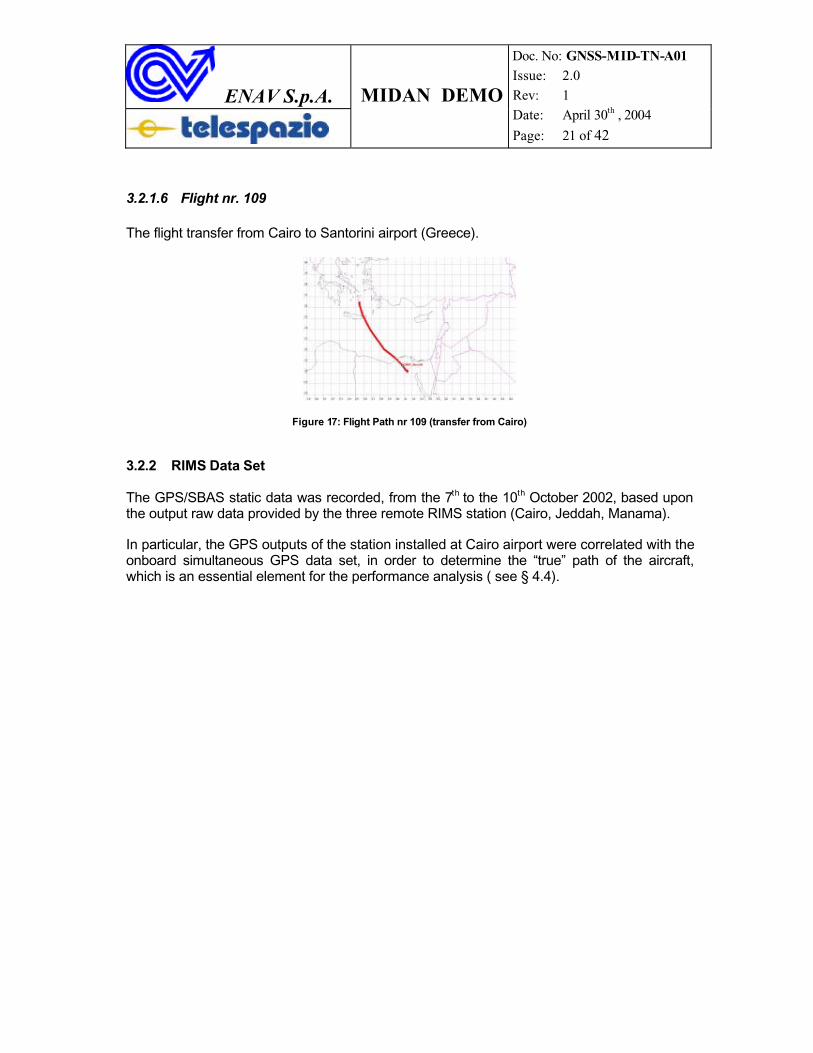
3.2.1.6 Flight nr. 109
The flight transfer from Cairo to Santorini airport (Greece).
Figure 17: Flight Path nr 109 (transfer from Cairo)
3.2.2 RIMS Data Set
The GPS/SBAS static data was recorded, from the 7th to the 10th October 2002, based upon the output raw data provided by the three remote RIMS station (Cairo, Jeddah, Manama).
In particular, the GPS outputs of the station installed at Cairo airport were correlated with the onboard simultaneous GPS data set, in order to determine the “true” path of the aircraft,which is an essential element for the performance analysis ( see § 4.4).
ENAV S.p.A. MIDAN DEMO
Doc. No: GNSS-MID-TN-A01 Issue: 2.0 Rev: 1 Date: April 30th , 2004
Page: 22 of 42
4 POST-FLIGHT ANALYSES
4.1 Methodology
During the data processing the following steps were undertaken:
a) derivation of the GPS+SBAS aircraft position;b) derivation of the Dilution Of Precision (DOP) parameters of GPS satellites;c) determination of the aircraft “true” path;d) comparison of the GPS “stand-alone” position against SBAS position;e) determination of the SBAS positioning errors;f) determination of the protection levels granted by SBAS during the tests;g) comparison of the protection levels with the “true” error along the time;h) determination and plot of the triangle plots (“Stanford” diagrams).
4.2 RIMS and Flight UP Row Data Pre-processing
RIMS static and User Platform (UP) flight data were stored as a number of binary files. These files required a pre-processing in order to come up with a more comprehensive data set, to be used for further calculations.
4.2.1 Use of ITT COTS
The ITT “RINEXP” software was used, in order to convert the RIMS data files into RINEX ASCII files.
4.2.2 SW Development for Flight Data Files Pre-processing
A series of TCL/TK and Scilab modules have been implemented in order to extract useful data from the UP binary stored data. UP data is distinguished by the message ID. TPZ software is capable to archive each message separately in order to use the data for further processing and analyses.
4.3 Final available data set
The final available data set consists of the following (for each flight test session):
- RINEX files for each RIMS station;- RINEX UP flight files;- Set of UP archived messages.
By making use of these set of data, next analyses have been performed.
ENAV S.p.A. MIDAN DEMO
Doc. No: GNSS-MID-TN-A01 Issue: 2.0 Rev: 1 Date: April 30th , 2004
Page: 23 of 42
4.4 “True” Path Calculation
A classical interferometric GPS methodology was adopted in order to perform a finecalculation of the flight path during the trials.
The true path reconstruction was based upon the analysis of two simultaneous sets of data: the RINEX files flight data and the RINEX files of a reference station. In order to contain the accuracy of the derived flight path within the appropriate (sub-metric) margin:
• the closest reference station (RIMS at Cairo airport) to the tested airspace waschosen;
• the range of the tested airspace from the reference station was set as 25NM.
It is pointed out that the accuracy of the “true” path has a direct effect on the level ofconfidence about the estimation of the errors and performance parameters.
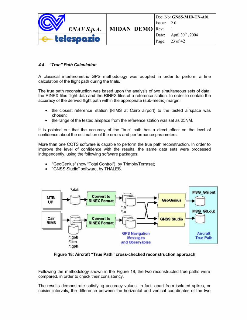
More than one COTS software is capable to perform the true path reconstruction. In order to improve the level of confidence with the results, the same data sets were processedindependently, using the following software packages:
• “GeoGenius” (now “Total Control”), by Trimble/Terrasat;• “GNSS Studio” software, by THALES.
Figure 18: Aircraft “True Path” cross-checked reconstruction approach
Following the methodology shown in the Figure 18, the two reconstructed true paths were compared, in order to check their consistency.
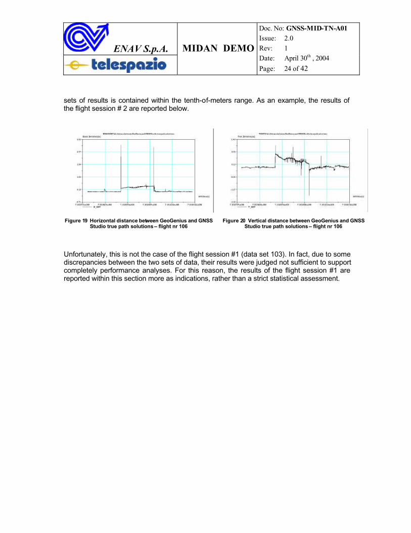
The results demonstrate satisfying accuracy values. In fact, apart from isolated spikes, or noisier intervals, the difference between the horizontal and vertical coordinates of the two
ENAV S.p.A. MIDAN DEMO
Doc. No: GNSS-MID-TN-A01 Issue: 2.0 Rev: 1 Date: April 30th , 2004
Page: 24 of 42
sets of results is contained within the tenth-of-meters range. As an example, the results of the flight session # 2 are reported below.
Figure 19 Horizontal distance between GeoGenius and GNSS Studio true path solutions – flight nr 106
Figure 20 Vertical distance between GeoGenius and GNSS Studio true path solutions – flight nr 106
Unfortunately, this is not the case of the flight session #1 (data set 103). In fact, due to some discrepancies between the two sets of data, their results were judged not sufficient to support completely performance analyses. For this reason, the results of the flight session #1 are reported within this section more as indications, rather than a strict statistical assessment.
ENAV S.p.A. MIDAN DEMO
Doc. No: GNSS-MID-TN-A01 Issue: 2.0 Rev: 1 Date: April 30th , 2004
Page: 25 of 42
5 TEST-BED PERFORMANCE
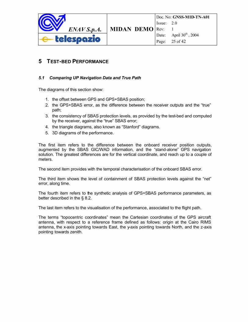
5.1 Comparing UP Navigation Data and True Path
The diagrams of this section show:
1. the offset between GPS and GPS+SBAS position;2. the GPS+SBAS error, as the difference between the receiver outputs and the “true”
path;3. the consistency of SBAS protection levels, as provided by the test-bed and computed
by the receiver, against the “true” SBAS error;4. the triangle diagrams, also known as “Stanford” diagrams.5. 3D diagrams of the performance.
The first item refers to the difference between the onboard receiver position outputs,augmented by the SBAS GIC/WAD information, and the “stand-alone” GPS navigation solution. The greatest differences are for the vertical coordinate, and reach up to a couple of meters.
The second item provides with the temporal characterisation of the onboard SBAS error.
The third item shows the level of containment of SBAS protection levels against the “net” error, along time.
The fourth item refers to the synthetic analysis of GPS+SBAS performance parameters, as better described in the § 8.2.
The last item refers to the visualisation of the performance, associated to the flight path.
The terms “topocentric coordinates” mean the Cartesian coordinates of the GPS aircraft antenna, with respect to a reference frame defined as follows: origin at the Cairo RIMS antenna, the x-axis pointing towards East, the y-axis pointing towards North, and the z-axispointing towards zenith.
ENAV S.p.A. MIDAN DEMO
Doc. No: GNSS-MID-TN-A01 Issue: 2.0 Rev: 1 Date: April 30th , 2004
Page: 26 of 42
5.2 Flight Session # 2 (Data set nr. 105)
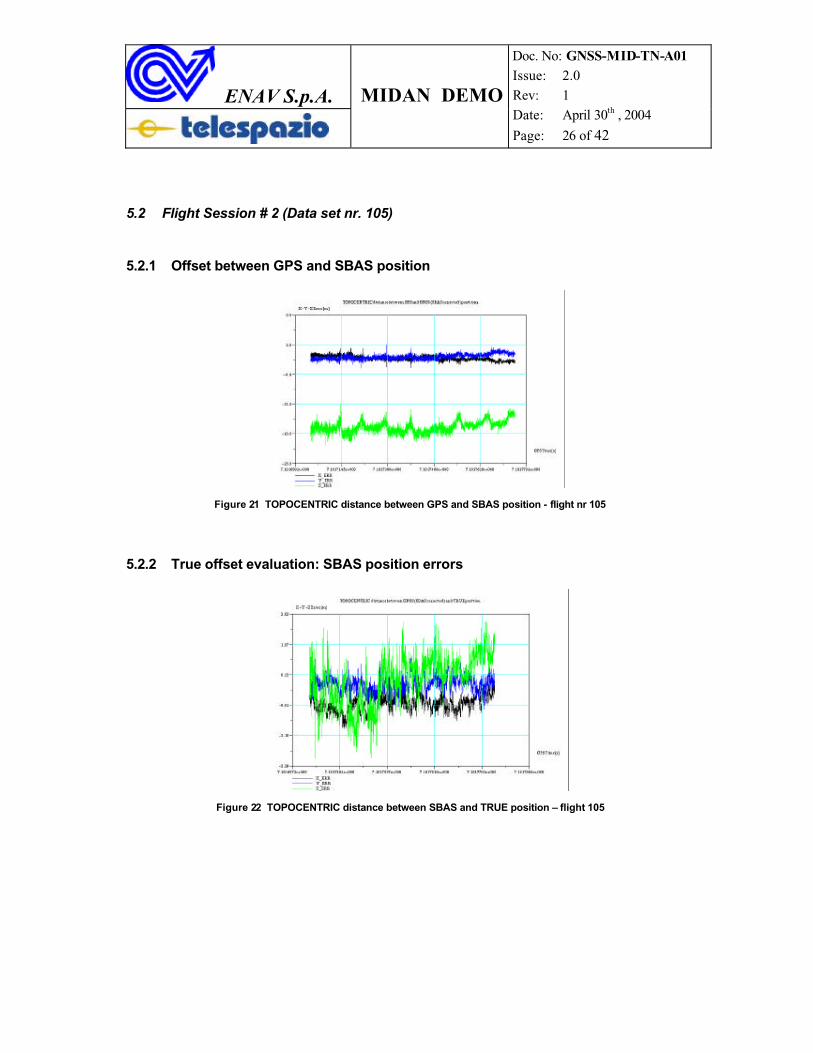
5.2.1 Offset between GPS and SBAS position
Figure 21 TOPOCENTRIC distance between GPS and SBAS position - flight nr 105
5.2.2 True offset evaluation: SBAS position errors
Figure 22 TOPOCENTRIC distance between SBAS and TRUE position – flight 105
ENAV S.p.A. MIDAN DEMO
Doc. No: GNSS-MID-TN-A01 Issue: 2.0 Rev: 1 Date: April 30th , 2004
Page: 27 of 42
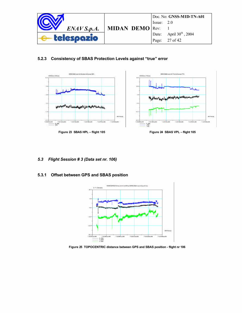
5.2.3 Consistency of SBAS Protection Levels against “true” error
Figure 23 SBAS HPL – flight 105 Figure 24 SBAS VPL – flight 105
5.3 Flight Session # 3 (Data set nr. 106)
5.3.1 Offset between GPS and SBAS position
Figure 25 TOPOCENTRIC distance between GPS and SBAS position - flight nr 106
ENAV S.p.A. MIDAN DEMO
Doc. No: GNSS-MID-TN-A01 Issue: 2.0 Rev: 1 Date: April 30th , 2004
Page: 28 of 42
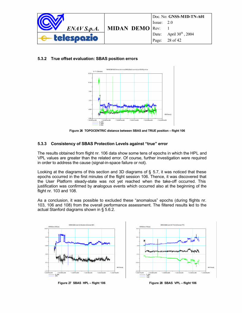
5.3.2 True offset evaluation: SBAS position errors
Figure 26 TOPOCENTRIC distance between SBAS and TRUE position – flight 106
5.3.3 Consistency of SBAS Protection Levels against “true” error
The results obtained from flight nr. 106 data show some tens of epochs in which the HPL and VPL values are greater than the related error. Of course, further investigation were required in order to address the cause (signal-in-space failure or not).
Looking at the diagrams of this section and 3D diagrams of § 5.7, it was noticed that these epochs occurred in the first minutes of the flight session 106. Thence, it was discovered that the User Platform steady-state was not yet reached when the take-off occurred. This justification was confirmed by analogous events which occurred also at the beginning of the flight nr. 103 and 108.
As a conclusion, it was possible to excluded these “anomalous” epochs (during flights nr. 103, 106 and 108) from the overall performance assessment. The filtered results led to the actual Stanford diagrams shown in § 5.6.2.
Figure 27 SBAS HPL – flight 106 Figure 28 SBAS VPL – flight 106
ENAV S.p.A. MIDAN DEMO
Doc. No: GNSS-MID-TN-A01 Issue: 2.0 Rev: 1 Date: April 30th , 2004
Page: 29 of 42
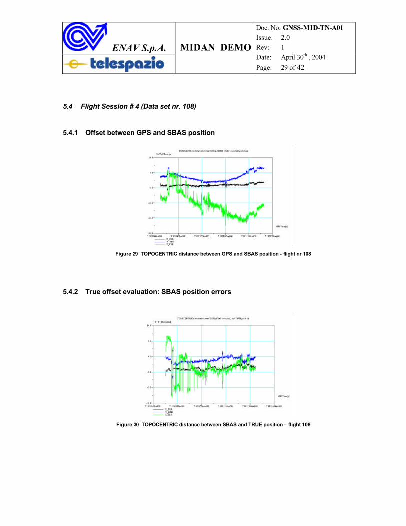
5.4 Flight Session # 4 (Data set nr. 108)
5.4.1 Offset between GPS and SBAS position
Figure 29 TOPOCENTRIC distance between GPS and SBAS position - flight nr 108
5.4.2 True offset evaluation: SBAS position errors
Figure 30 TOPOCENTRIC distance between SBAS and TRUE position – flight 108
ENAV S.p.A. MIDAN DEMO
Doc. No: GNSS-MID-TN-A01 Issue: 2.0 Rev: 1 Date: April 30th , 2004
Page: 30 of 42
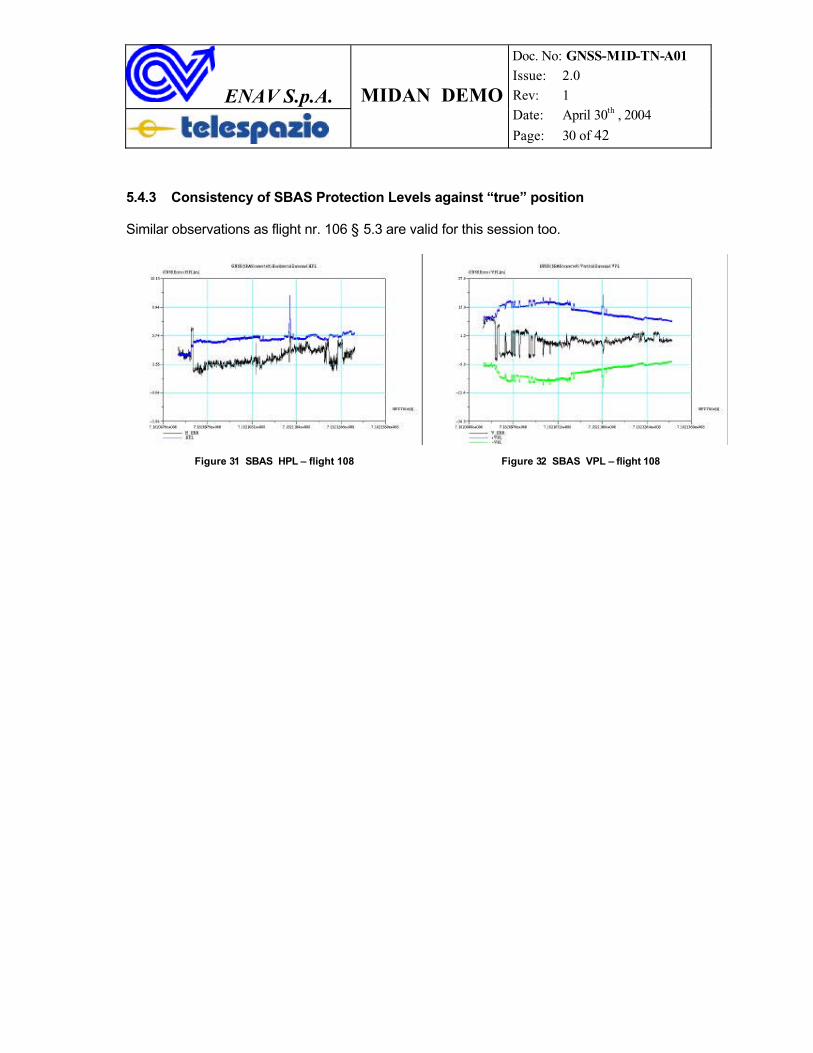
5.4.3 Consistency of SBAS Protection Levels against “true” position
Similar observations as flight nr. 106 § 5.3 are valid for this session too.
Figure 31 SBAS HPL – flight 108 Figure 32 SBAS VPL – flight 108
ENAV S.p.A. MIDAN DEMO
Doc. No: GNSS-MID-TN-A01 Issue: 2.0 Rev: 1 Date: April 30th , 2004
Page: 31 of 42
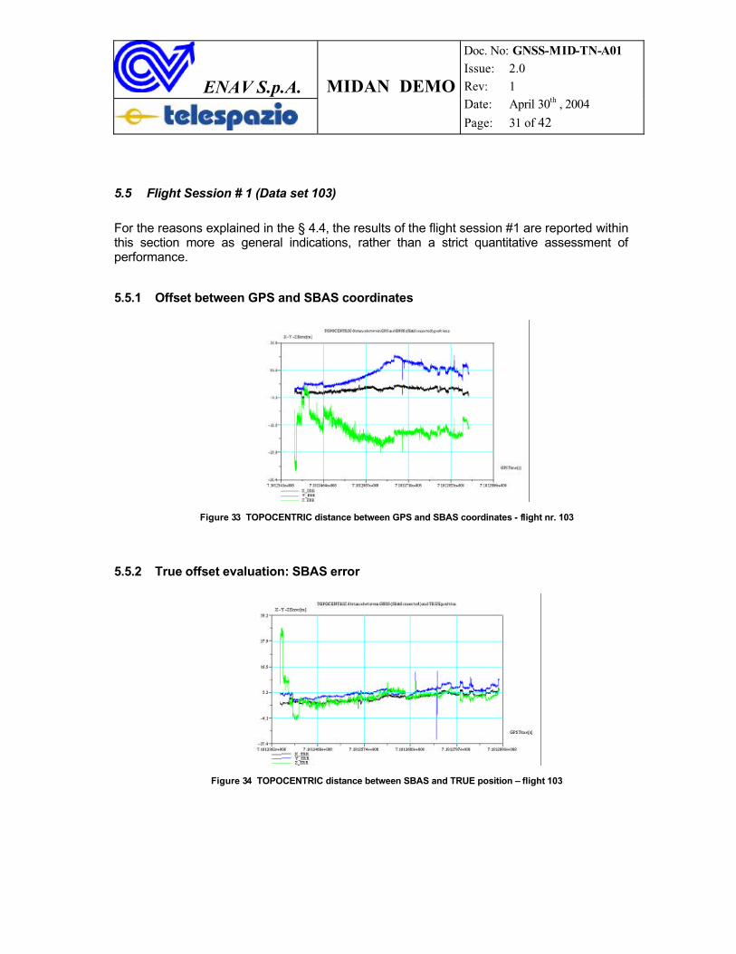
5.5 Flight Session # 1 (Data set 103)
For the reasons explained in the § 4.4, the results of the flight session #1 are reported within this section more as general indications, rather than a strict quantitative assessment ofperformance.
5.5.1 Offset between GPS and SBAS coordinates
Figure 33 TOPOCENTRIC distance between GPS and SBAS coordinates - flight nr. 103
5.5.2 True offset evaluation: SBAS error
Figure 34 TOPOCENTRIC distance between SBAS and TRUE position – flight 103
ENAV S.p.A. MIDAN DEMO
Doc. No: GNSS-MID-TN-A01 Issue: 2.0 Rev: 1 Date: April 30th , 2004
Page: 32 of 42
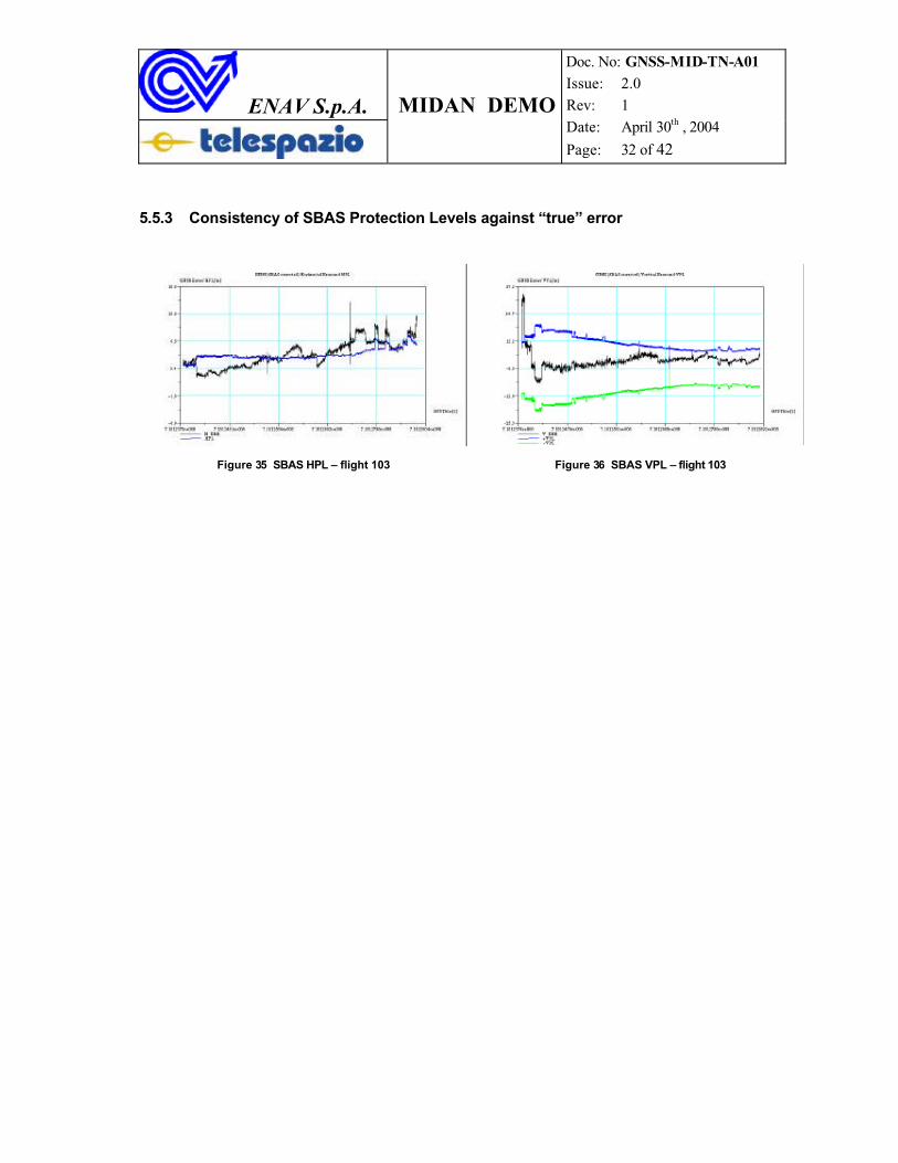
5.5.3 Consistency of SBAS Protection Levels against “true” error
Figure 35 SBAS HPL – flight 103 Figure 36 SBAS VPL – flight 103
ENAV S.p.A. MIDAN DEMO
Doc. No: GNSS-MID-TN-A01 Issue: 2.0 Rev: 1 Date: April 30th , 2004
Page: 33 of 42
5.6 Stanford Diagrams
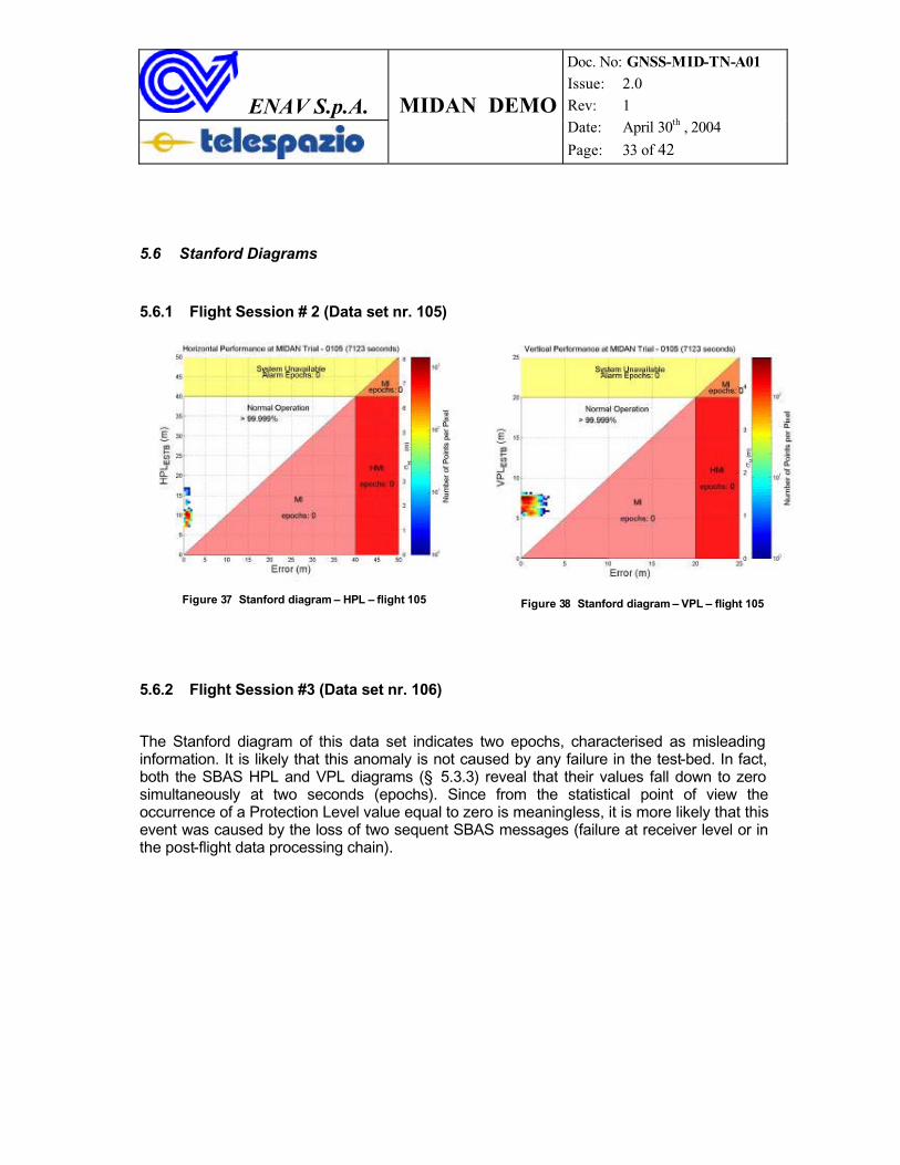
5.6.1 Flight Session # 2 (Data set nr. 105)
Figure 37 Stanford diagram – HPL – flight 105 Figure 38 Stanford diagram – VPL – flight 105
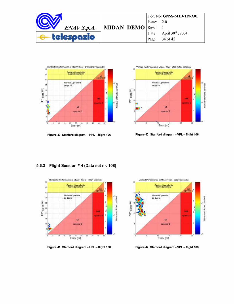
5.6.2 Flight Session #3 (Data set nr. 106)
The Stanford diagram of this data set indicates two epochs, characterised as misleading information. It is likely that this anomaly is not caused by any failure in the test-bed. In fact, both the SBAS HPL and VPL diagrams (§ 5.3.3) reveal that their values fall down to zero simultaneously at two seconds (epochs). Since from the statistical point of view theoccurrence of a Protection Level value equal to zero is meaningless, it is more likely that this event was caused by the loss of two sequent SBAS messages (failure at receiver level or in the post-flight data processing chain).
ENAV S.p.A. MIDAN DEMO
Doc. No: GNSS-MID-TN-A01 Issue: 2.0 Rev: 1 Date: April 30th , 2004
Page: 34 of 42
Figure 39 Stanford diagram – HPL – flight 106 Figure 40 Stanford diagram – VPL – flight 106
5.6.3 Flight Session # 4 (Data set nr. 108)
Figure 41 Stanford diagram – HPL – flight 108 Figure 42 Stanford diagram – VPL – flight 108
ENAV S.p.A. MIDAN DEMO
Doc. No: GNSS-MID-TN-A01 Issue: 2.0 Rev: 1 Date: April 30th , 2004
Page: 35 of 42
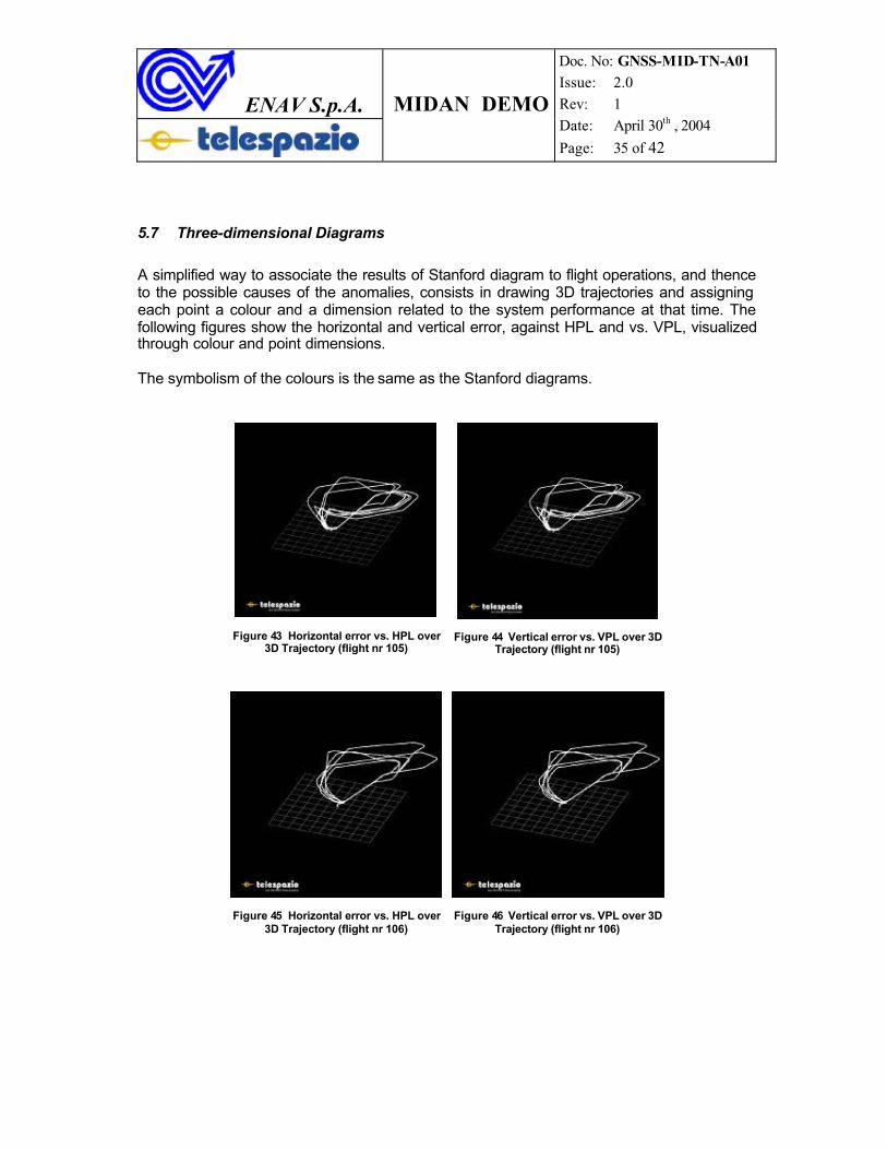
5.7 Three-dimensional Diagrams
A simplified way to associate the results of Stanford diagram to flight operations, and thence to the possible causes of the anomalies, consists in drawing 3D trajectories and assigningeach point a colour and a dimension related to the system performance at that time. The following figures show the horizontal and vertical error, against HPL and vs. VPL, visualized through colour and point dimensions.
The symbolism of the colours is the same as the Stanford diagrams.
Figure 43 Horizontal error vs. HPL over 3D Trajectory (flight nr 105)
Figure 44 Vertical error vs. VPL over 3D Trajectory (flight nr 105)
Figure 45 Horizontal error vs. HPL over 3D Trajectory (flight nr 106)
Figure 46 Vertical error vs. VPL over 3D Trajectory (flight nr 106)
ENAV S.p.A. MIDAN DEMO
Doc. No: GNSS-MID-TN-A01 Issue: 2.0 Rev: 1 Date: April 30th , 2004
Page: 36 of 42
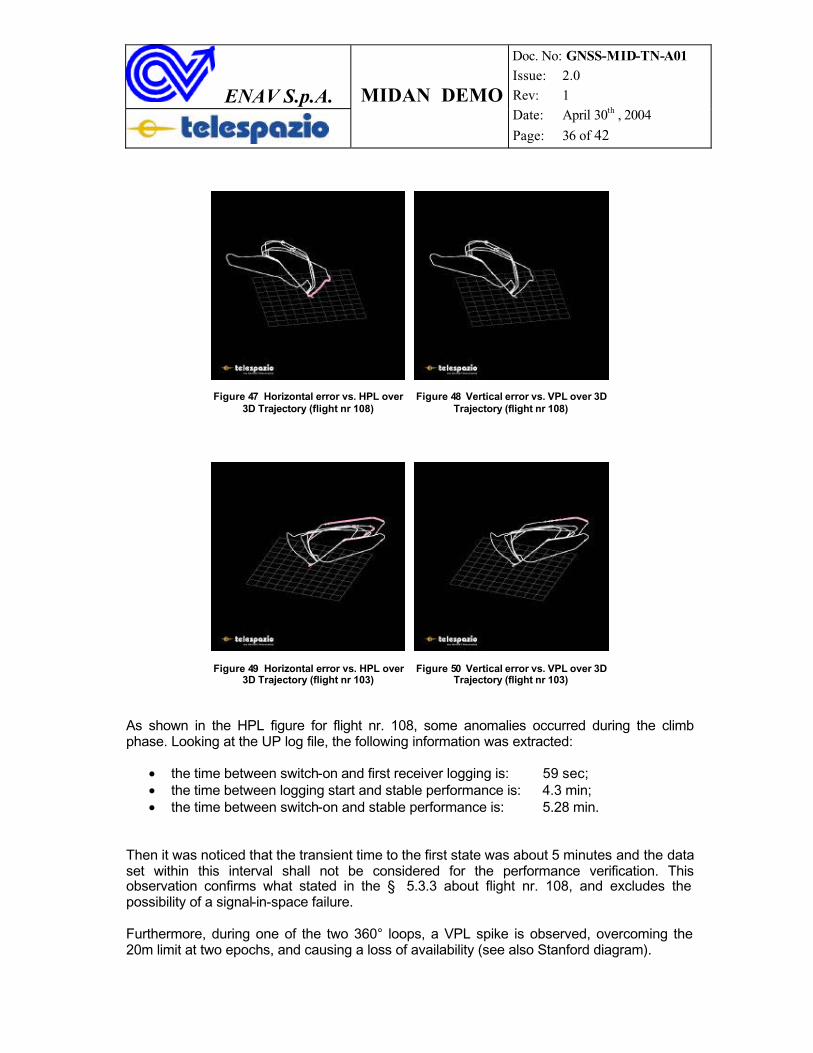
Figure 47 Horizontal error vs. HPL over3D Trajectory (flight nr 108)
Figure 48 Vertical error vs. VPL over 3D Trajectory (flight nr 108)
Figure 49 Horizontal error vs. HPL over 3D Trajectory (flight nr 103)
Figure 50 Vertical error vs. VPL over 3D Trajectory (flight nr 103)
As shown in the HPL figure for flight nr. 108, some anomalies occurred during the climbphase. Looking at the UP log file, the following information was extracted:
• the time between switch-on and first receiver logging is: 59 sec;• the time between logging start and stable performance is: 4.3 min;• the time between switch-on and stable performance is: 5.28 min.
Then it was noticed that the transient time to the first state was about 5 minutes and the data set within this interval shall not be considered for the performance verification. Thisobservation confirms what stated in the § 5.3.3 about flight nr. 108, and excludes the possibility of a signal-in-space failure.
Furthermore, during one of the two 360° loops, a VPL spike is observed, overcoming the 20m limit at two epochs, and causing a loss of availability (see also Stanford diagram).
ENAV S.p.A. MIDAN DEMO
Doc. No: GNSS-MID-TN-A01 Issue: 2.0 Rev: 1 Date: April 30th , 2004
Page: 37 of 42
6 CONCLUSIONS
The ESTB/MTB measured performance during the MIDAN Demo has shown a performance level in the tested region, which meets both the ICAO horizontal and vertical requirements for APV 1 in all the cases, and APV 2 vertical requirements (horizontal accuracy is the same for: APV1, APV2 and CAT I) for most of them. Thence, the results are satisfactory and in line with the expectations in terms of system performance.
However, it is pointed out that complete considerations of the results achieved during the tests shall take into account:
• the minimal ground infrastructure of the ESTB/MTB used;• the particular/stressed manoeuvres (i.e. circular patterns or bank angles up to 60°)
performed by the flight test airplane;• the use of experimental hardware and software;• the handing of data having different formats.
At the light of the above it may be concluded that:
1) the extension of the EGNOS system architecture is technically feasible if adequate EGNOS ground segment upgrades are provided (e.g. addition of reference stations in the Region);
2) the EGNOS services may be eventually provided in the ICAO MID Region with satisfactory performances (down to APV 2 service level).
Therefore, it is recommended to plan further test activities, supported by an adequate system engineering activity to assess in detail:
a) the actual extension of EGNOS in the Region;b) the actual performance of the extended system.
ENAV S.p.A. MIDAN DEMO
Doc. No: GNSS-MID-TN-A01 Issue: 2.0 Rev: 1 Date: April 30th , 2004
Page: 38 of 42
7 ACKNOWLEDGEMENTS
ENAV wishes to thank very much all the Organisations and Companies who participated in the preparation and execution of the Demonstration, and in particular:
� ESA-EGNOS Project Office, that managed the activities of the ESTB and its operations with the Italian MTB and performed some of the post-flight analyses;
� European Commission, that encouraged such activity and provided all the necessary support for the feasibility of the Demo;
� ICAO Office of MID Region, for the kind support in the coordination of the activities of the hosting sites;
� National Air Navigation Services Company (NANSC) of Egyptian Holding Company for Airports and Air Navigation, that permitted the flight trials on Cairo airport and hosted one Test Bed Reference Station, providing all the logistic and technical support for its installation.
� Presidency of Civil Aviation - Kingdom of Saudi Arabia – (PCA) that hosted a Test Bed Reference Station at his premises, providing all the logistic and technical support for its installation.
� Bahrain Civil Aviation Authority (CAA), that hosted a Test Bed Reference Station at the Bahrain Airport, providing all the logistic and technical support for its installation.
� all the staff of ENAV S.p.A. and Telespazio S.p.A., that worked jointly hardly to achieve the objective.
ENAV S.p.A. MIDAN DEMO
Doc. No: GNSS-MID-TN-A01 Issue: 2.0 Rev: 1 Date: April 30th , 2004
Page: 39 of 42
8 BACKGROUND INFORMATION
8.1 Performance-related Concepts
The error (also NSE: Navigation System Error) is the deviation of navigation solutionprovided by the GNSS receiver with respect to the “true” user position.
During the analysis of a huge amount of data collected during MIDAN Demo, a large effort is devoted in determining the error, by reconstructing the aircraft “true path”, based upon a sophisticated processing of the carrier phase measurements from the GNSS receiver.
The 3-D vector error is typically projected in “local horizon coordinates”, so that a horizontal and a vertical component are identified.
The out of tolerance condition can be intuitively understood as a growth of the error beyond specified alarm thresholds that are, in fact, known as Horizontal or Vertical Alert Limits (HAL and VAL) and which depend on flight phase, as specified by ICAO SARPs.
At this purpose, the SBAS integrity channel allows the user receiver to compute theHorizontal and Vertical Protection Levels (HPL and VPL), so that a better characterisation of the possible integrity related events is given, according to ICAO SARPs, summarised as follows:
- there is a “Misleading Information” (MI), when (NSE > HPL) or (NSE > VPL) whilst, at the same time, the NSE remains below the alert limits (HAL and VAL). In other words, the user has underestimated its navigation error, but still the situation does not result in an imminent life risk, due to the fact that alert limits are not trespassed.
- there is an “Hazardously Misleading Information” (HMI) case, when NSE > (HAL or VAL), whilst (HPL and VPL) remain below the alert limits (HAL and VAL). The user has underestimated its navigation error, that is beyond alert limits: the situation isdangerous and not under control, as it is not clear “how far” the NSE is from prescribed thresholds.
ENAV S.p.A. MIDAN DEMO
Doc. No: GNSS-MID-TN-A01 Issue: 2.0 Rev: 1 Date: April 30th , 2004
Page: 40 of 42
8.2 “Stanford” Diagrams
Triangle plots, commonly referred as “Stanford” diagrams, are a useful syntheticrepresentation of the performance parameters during the interval of the measurements.These diagrams are divided into five areas, each representing a peculiarity. More precisely, (taking into account, as an example, the horizontal coordinates):
White: the horizontal error is smaller than both HPL and HAL (Normal Operation);
Pink: the horizontal error is greater than HPL and smaller than HAL (Misleading Information);
Yellow: the horizontal error is smaller than HPL, but HPL is greater than HAL (Systemunavailable);
Orange: the horizontal error is greater than HPL and HPL is greater than HAL(Misleading Information);
Red the horizontal error is greater than both HPL and HAL, while HPL is below the HAL (Hazardous Misleading Information).
ENAV S.p.A. MIDAN DEMO
Doc. No: GNSS-MID-TN-A01 Issue: 2.0 Rev: 1 Date: April 30th , 2004
Page: 41 of 42
8.3 Reference Documents
The following items are suggested as reference for a better understanding of the present document:
[ 1 ] ESA EGNOS Project Office - MIDAN Data Post Processing Results 17/09/03, Issue 1 Rev. 0;
[ 2 ] ICAO - Annex 10;
[ 3 ] “Minimum Operational Performance Standards for GPS/WAAS Airborne Equipment, RTCA/DO-229A”, June 9, 1998;
[ 4 ] MTB Flight Trials”, R. Pasquali et al., GNSS’98, Tolouse, France;
[ 5 ] “MTB: Current and Future Activities”, S. Viviano et al., GNSS’99, Genova;
[ 6 ] RTCA DO-229C – Minimum Operational Performance Standarsd (MOPS) for GPS WAAS Airborne Equipment;
[ 7 ] Benoit Roturier (DGAC/STNA), Eric Chatre (DGAC/STNA), Javier Ventura-Traveset(ESA) - “The SBAS Integrity Concept Standardized by ICAO. Application toEGNOS”;
[ 8 ] G. Del Duca, A. Nuzzo, C. Rinaldi, R.Pasquali, R. Perago, - “MIDAN DEMO Euro-Mediterranean The first SBSBAS Flight Trials in the Middle-East Region” –Proceedings of GNSS 2003 Symposium.
ENAV S.p.A. MIDAN DEMO
Doc. No: GNSS-MID-TN-A01 Issue: 2.0 Rev: 1 Date: April 30th , 2004
Page: 42 of 42
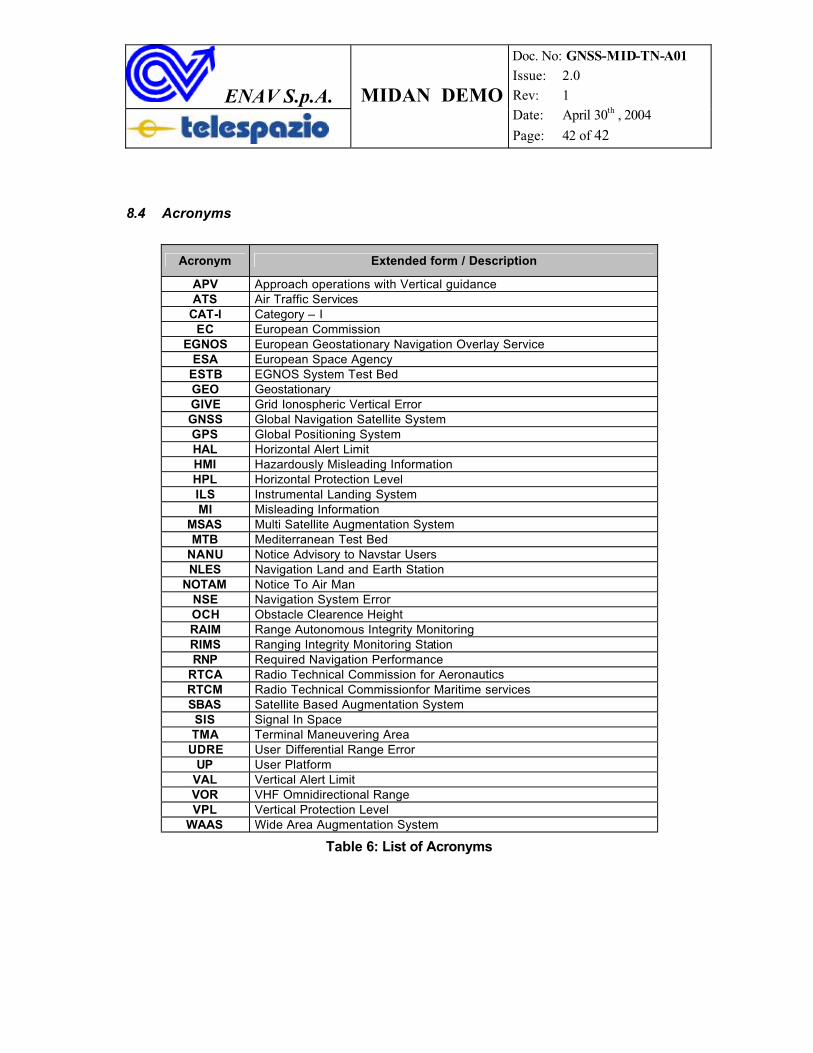
8.4 Acronyms
Acronym Extended form / Description
APV Approach operations with Vertical guidanceATS Air Traffic Services
CAT-I Category – IEC European Commission
EGNOS European Geostationary Navigation Overlay ServiceESA European Space Agency
ESTB EGNOS System Test BedGEO GeostationaryGIVE Grid Ionospheric Vertical ErrorGNSS Global Navigation Satellite SystemGPS Global Positioning SystemHAL Horizontal Alert LimitHMI Hazardously Misleading InformationHPL Horizontal Protection LevelILS Instrumental Landing SystemMI Misleading Information
MSAS Multi Satellite Augmentation SystemMTB Mediterranean Test Bed
NANU Notice Advisory to Navstar UsersNLES Navigation Land and Earth Station
NOTAM Notice To Air ManNSE Navigation System ErrorOCH Obstacle Clearence HeightRAIM Range Autonomous Integrity MonitoringRIMS Ranging Integrity Monitoring StationRNP Required Navigation Performance
RTCA Radio Technical Commission for AeronauticsRTCM Radio Technical Commissionfor Maritime servicesSBAS Satellite Based Augmentation SystemSIS Signal In SpaceTMA Terminal Maneuvering Area
UDRE User Differential Range ErrorUP User Platform
VAL Vertical Alert LimitVOR VHF Omnidirectional RangeVPL Vertical Protection Level
WAAS Wide Area Augmentation System
Table 6: List of Acronyms
GNSS TF/4-REPORT APPENDIX 3B
GNSS TF/4
Appendix 3B to the Report on Agenda Item 3
Improvement of NAVIGATION SYSTEMS in the MID Region
Document Reference: MIDANPIRG GNSS – TF/AG
Author: GNSS TF Action Group
Revision Number: Version 01 / 2004
Date: May 2004

EVALUATION and PLANNING of RADIONAVIGATION FACILITIES
in the MID REGION

Table of Contents
1. Introduction
2. Evaluation of the existing facilities
2.1 Review of Flight information Regions (FIRs)
2.2 Review of existing navigation aids
2.2.1 En-route navigation aids
2.2.2 Precision approach aids
2.2.3 Non precision approach aids
2.3 Review of existing communication infrastructures
2.3.1 General
2.3.2 Domestic satellite networks
2.3.2.1 Egyptian satellite network
2.3.2.2 Yemenite satellite network
2.3.2.3 Iraqi satellite network
2.3.2.4 Kuwait satellite network
2.3.1.5 Iranian satellite network
2.3.1.6 Sudanese satellite network
3. Development Plans
3.1 Introduction
3.2 Directions
3.2.1 Communications
3.2.2 Navigation
3.3 Near term development plans
3.3.1 Communications
3.3.1.1 MID VSAT network
3.3.2 Navigation
3.3.2.1 NAVISAT
4. Conclusions
GNSS TF/4-REPORT APPENDIX 3B
3B-1
1. INTRODUCTION 1.1 The objective of this study is to define some inputs for the GNSS Implementation Strategy in the Middle East Region. To do so, the evaluation of the existing navigation systems and communication infrastructures in the Region will be performed, as well as the review of the related development plans. 1.2 The analysis of the existing navigation infrastructure will show minimum constraints for the operational requirements and will contribute to the benefits provided by the satellite -based navigation regarding the cost benefit analysis. 1.3 The analysis of the existing communication infrastructure will allow defining what may be re-used for GNSS augmentation and what needs to be implemented. This will influence the system architecture and the cost benefit analysis. 2. EVALUATION OF THE EXISTING FACILITIES 2.1 Review of Flight Information Regions (FIRs) The Middle East Region is organized into 14 Flight Information Regions that support the Air routes areas. 2.2 Review of existing navigation aids The present radio-navigation aids infrastructure is composed of locators, NDBs, VOR/DME and ILS. Most of these requirements comply with the Middle East Air navigation Plan and the others are implemented by States for their own national needs. 2.2.1 En-route navigation Aids The Middle East Region is well covered by en-route navigation aids, however improvement is expected in the northeast part where it is noted a low density of aids.
- 50 VOR are operational and 16 have not yet been implemented - 89 DME are operational, 4 unserviceable and 8 have not yet been implemented - 23 NDBs and 12 Locators are operational
2.2.2 Precision Approach Aids All countries have implemented at least one CAT I precision approach located at their international airports. Some of the States have at their disposal CAT II and CAT III precision approach equipments at their main airports. Recently, two of these equipments were downgraded due to either harmful interferences or to signal instability. There are currently 62 ILS installed out of 90 required for the Region. Out of these 62 ILS, 56 are serviceable. This means that 69 per cent of the requirement for precision approach capability is fulfilled.
In the meantime, 73 per cent of DME and 72 per cent of VOR are implemented.
The table CNS 3 of the MID FASID shows the distribution of the approach radio navigation aids implemented in the Region.
GNSS TF/4-REPORT APPENDIX 3B
3B-2
2.2.3 Non Precision Approach Aids The other airports of the Middle East Region have either instrument approach runways, allowing NPA approaches with the instruments, or non-instrument approach runways. Out of the 204 runways of the 139 airports included in the table CNS 3, there are 89 instrument approach runways and 115 non-instrument runways. Most instrument approach runways are provided with a VOR/DME. In consequence, NPA approaches are currently possible on 57 per cent of the runways. 2.3 Review of existing communication Infrastructures 2.3.1 General The communication means provided by States, at national or international level, include the following services:
- The Aeronautical Mobile Service (AMS) which includes all communications with aircraft for air traffic control and airspace management. These services are mainly achieved by vocal communications either on VHF (continental area) or HF (remote and oceanic area). Most of the continental area of the Middle East Region is covered by extended and improved VHF communications.
- The Aeronautical Fixed Service (AFS) that includes all point-to-point communications for Air Traffic Control, Meteorology, Search and Rescue. These services are provided by vocal and data communications.
The major elements of the AFS are the AFTN (Aeronautical Fixed telecommunications Network) for data communications and the ATS/DS network (Air traffic Services Direct Speech) for voice communications. It is worth noting that many States have improved their AFTN circuits by using CIDIN protocol with high reliability links. 2.3.2 Domestic satellite networks Five VSAT domestic networks are operating in the Middle East Region and are aimed at extending VHF communications, improving AFTN and ATS/DS communications with secondary airports. The results gained from this experience have led the MID States to agree for the study of the so called the MID VSAT network intended to cover all Middle East Region and, at the same time, to ensure connectivity with the adjacent Regions (EUR, AFI and ASIA-PAC). Another domestic satellite network is operating in a neighboring country: Sudan 2.3.2.1 Egyptian satellite network The domestic network has a star configuration and is composed of one hub station installed in Cairo and twelve VSAT remote stations spread over the Cairo FIR. These remote stations support the VHF extended coverage, AFTN, ATS/DS, Radar coverage, AIS and the maintenance communications.
GNSS TF/4-REPORT APPENDIX 3B
3B-3
The network is now congested and does not allow anymore any integration with other networks. The Egyptian Authorities are planning a new domestic VSAT network to solve this inadequacy. 2.3.2.2 Yemenite satellite network The domestic network is composed of one hub station and six VSAT remote stations spread over the Sana’a FIR. These remote stations can support the VHF extended coverage, AFTN, ATS/DS, Radar coverage and the maintenance communications. The configuration of the network allows its extension and integration to other networks. 2.3.2.3 Iraqi satellite network (non documented) 2.3.2.4 Kuwait satellite network (non documented) 2.3.2.5 Iranian satellite network (non documented) 2.3.2.6 Sudanese satellite network The Aeronautical Telecommunication Service is in the process of full restructuring with the implementation of nine VHF remote stations spread in the Khartoum FIR. These remote stations which are supported by a domestic VSAT network, are still under tests. The main objective of the network is to provide aeronautical fixed and aeronautical mobile services in Khartoum FIR. Moreover, the current provisions allow the Ministry of Aviation to implement and to operate a VSAT network for safety purposes, as an usual telecommunications service provider. 3. DEVELOPMENT PLANS 3.1 Introduction The Middle East Regional Navigation Plan provides the principles and the direction that shall be consistently followed by all States, services providers and users within the Region. 3.2 Directions 3.2.1 Communications According to the global recommendations set by ICAO, the direction to follow is the evolution towards satellite communications means that will support both voice and data transmissions (including GNSS augmentation data transmissions). During the long transition period, extended and VHF data communications means should be developed and deployed to allow a broader coverage and reliable data transmissions in the remote areas.
GNSS TF/4-REPORT APPENDIX 3B
3B-4
3.2.2 Navigation The VOR equipment will remain the main navigation means on traditional ATS routes. The traffic shall be passed gradually from ATS routes to RNAV ones, and the airspace shall be consequently restructured. The ILS equipment will be maintained at least until 2010, and any equipment withdrawal will be announced to the users several years in advance. En route as well as approaches will be gradually supported by GNSS whose operational performances will be extensively demonstrated during various experimental campaigns. 3.2.3 Surveillance The implementation and usage of SSRs and ADS should be broadened. 3.3 Near term development plans 3.3.1 Communications The development plans for the communication infrastructures are part of the overall improvement plan for air traffic control and airspace management with future system technologies. The main example of network project is the MID VSAT project. MIDANPIRG/8 meeting approved the feasibility study of the MID VSAT project that should be refined by updated information received from States. 3.3.1.1 MID VSAT Network The planned MID VSAT network will cover all MID Region and ensure connectivity with the neighboring Regions (AFI, EUR and ASIA-PAC). The F type stations could be used by States on the main airports, with the respective transmission rates of 64, 128 and 256 Kbps Voice and data are transmitted over Frame Relay, where - the VHF and ATS/DS voice communications use 8 Kbps channel - the AFTN data applications use 2.4 Kbps channel - the radar and supervision data applications use 9.6 Kbps channel Coordination has been made with other similar projects, especially with NAFISAT project (AFI Region) to operate TDMA technique over INTELSAT 1002. 3.2.2 Navigation The existing navaids infrastructure will continue to be used for a certain time in the future, as no alternative for its replacement is available yet. Improvement to the existing infrastructure is sought through replacement of very old facilities, better maintenance and regular flight checking. Decommissioning of the VOR/DME and ILS equipments is not contemplated before 2015. Any equipment withdraw will be announced to its potential users several years in advance.

GNSS TF/4-REPORT APPENDIX 3B
3B-5
3.2.2.1 NAVISAT network
(to be developed) 4. SUMMARY It appears that there is no urgent need for augmentation navigation service in the near term on both en-route and approaches. Moreover, the existing satellite navigation systems can be used as supplemental means for en-route navigation, terminal and NPA for some airports. The Middle East Region must put all efforts in the implementation of a dedicated MID VSAT network which will be used for ground– ground data and voice communications and also serves as an important step in planning for transition to CNS/ATM systems.

GNSS TF/4-REPORT APPENDIX 3B
3B-6
Implementation of Requirements
(to be developed)
GNSS TF/4-REPORT APPENDIX 3C
GNSS TF/4 Appendix 3C to the Report on Agenda Item 3
REVISED STRATEGY FOR THE IMPLEMENTATION OF GNSS NAVIGATION CAPABILITY IN THE MID REGION
Considering that:
1) Safety is the highest priority; 2) Elements of Global Air Navigation Plan for CNS/ATM System on GNSS and requirements for
the GNSS implementation will be incorporated into the CNS part of FASID; 3) GNSS Standards and Recommended Practices (SARPs), PANS and guidance material for
GNSS implementation are available; 4) The availability of avionics including limitations of some receiver designs; the ability of aircraft
to achieve RNP requirements and the level of user equipage; 5) Development of GNSS systems including satellite constellations and improvement in system
performance; 6) Airworthiness and operational approvals allowing the current GNSS to be applied for en-route
and non precision approach phases of flight without the need for augmentation services external to the aircraft;
7) Development status of aircraft-based augmentation systems; 8) Regional augmentation systems include both satellite-based and ground-based systems; and 9) Human, environmental and economic factors will affect the implementation.
The general strategy for the implementation of GNSS in the MID Region is detailed below. This strategy is based on the regional navigation requirements of:
a) RNP 10 for en-route in remote/oceanic areas; b) RNP 5 for en-route; c) NPA/APV for approaches; and
d) Precision approaches at selected airports. 1) There should be an examination of the extent to which the GNSS system accessible in the
Region can meet the navigational requirements of ATM service providers and aircraft operators in the Region;
2) Evolutionary introduction of GNSS Navigation Capability should be consistent with the Global
Air Navigation Plan for CNS/ATM systems; 3) Implementation should be in full compliance with ICAO Standards and Recommended
Practices and PANS; 4) Introduce the use of GNSS for navigation in remote/oceanic areas;

GNSS TF/4-REPORT APPENDIX 3C
3C-2
5) Introduce the use of GNSS with appropriate augmentation systems, as required, for en-route
navigation and non-precision approach; 6) Any external augmentation system deemed necessary for the implementation of GNSS for a
particular flight phase in an area under consideration (SBAS/GBAS including ground-based regional augmentation system) should be implemented in full compliance with ICAO SARPs;
7) To the extent possible, States should work co-operatively on multinational basis to implement
GNSS augmentation system in order to facilitate seamless and inter-operable systems; 8) States consider segregating traffic according to navigation capability and granting preferred
routes to aircraft with better navigation performance with the exception to State aircraft; 9) States undertake a coordinated R& D program on GNSS implementation and operation; 10) ICAO and States should undertake education and training programs to provide necessary
knowledge in GNSS theory and operational application; and 11) States establish multidisciplinary GNSS implementation teams, using section 6.10.2 of ICAO
Circular 267, Guidelines for the Introduction and Operational Approval of the GNSS, as a guide.
----------
GNSS TF/4-REPORT 4-1
GNSS TF/4
Report on Agenda Item 4
REPORT ON AGENDA ITEM 4: REVIEW OF RECENT DEVELOPMENTS, RESEARCHES IN RELATION WITH THE IMPLEMENTATION OF GNSS
4.1 Under this Agenda Item, the meeting was presented with an overview of the recent developments in relation with the implementation of GNSS based mainly on the outcome of the 11 th Air Navigation Conference. The meeting noted that work related to air navigation systems and, in particular, development and implementation continue to rank the highest priority items on ICAO’s work programme. 4.2 In this regard, the 11th Air Navigation Conference had developed a set of recommendations which are in Appendix 4A to the report on Agenda Item 4. The meeting noted that particular emphasis was put on the gradual transition from the current terrestrial navigation infrastructure to the increased use of satellite navigation infrastructure. 4.3 Reviewing the issue related the impact of electromagnetic interference on radio navigation systems, the meeting noted that ICAO will developed a material to assist States in assessing potential interference from FM broadcasting stations. 4.4 The meeting noted also that some States had already developed preventive and remedial actions to protect aeronautical communication and navigation systems from harmful interference. 4.5 In the light of the above, the meeting was of the view that the recommendation 5/2 formulated by the 11th Air Navigation Conference was an important way to solve the harmful interference issue of FM broadcasting on navigation systems. The Recommendation 5/2 of the 11th Air Navigation Conference is quoted below: RECOMMENDATION 5/2: ICAO ACTIVITIES ON INTERFERENCE That ICAO,
a) intensify its activities to secure protection of aeronautical communication, navigation and surveillance systems from the adverse effects of electromagnetic interference and develop guidance material, as necessary;
b) develop material to assist States in assessing interference from FM
broadcasting stations; c) support the relevant activities of the ITU and regional
telecommunication and standards-making organizations; and d) develop guidance material on the control and removal of interference
to aeronautical systems. 4.6 The meeting was informed that the 11th Air Navigation Conference had requested new additional GNSS frequencies that would be submitted in accordance with the conditions specified in ITU Regulations. 4.7 As a matter of priority and in order to protect GNSS from harmful interference, the meeting stressed the Experts to follow the issue related the deletion of country’s name from the footnotes 5.362B and 5.362C of the ITU WRC-2003. In parallel, the ICAO Office was requested to send a reminder letter to draw the attention on the importance of this subject to the following States: Egypt – Iraq – Israel – Jordan - Kuwait – Lebanon – Qatar – Saudi Arabia and Syria.
----------------
GNSS TF/4-REPORT APPENDIX 4A
GNSS TF/4 Appendix 4A to the Report on Agenda Item 4
11th Air Navigation Recommendations related to GNSS Recommendation 6/1: Transition to satellite-based air navigation That,
a) ICAO continue to develop as necessary provisions which would support seamless GNSS guidance for all phases of flight and facilitate transition to satellite-based sole navigation service with due consideration of safety of flight, technical, operational and economics factors;
b ) air navigation service providers move rapidly, in coordination with airspaces
users, with a view to achieving, as soon as possible, worldwide navigation capability to at least APV I performance; and
c) States and airspace users take note of available and upcoming SBAS navigation
services providing for APV operations and take necessary steps towards installation and certification of SBAS capable avionics.
Recommendation 6/2: Guidelines on mitigation of GNSS vulnerabilities That States in their planning and introduction of GNSS services:
a) assess the likelihood and effects of GNSS vulnerabilities in their airspace and utilize, as necessary, the mitigation methods as outlined in the guidelines contained in Appendix A to the report on Agenda Item 6;
b ) provide effective spectrum management and protection of GNSS frequencies to
reduce the possibility of unintentional interference;
c) take full advantage of on-board mitigation techniques, particularly inertial navigation;
d) where determined that terrestrial navigation aids need to be retained as part of an
evolutionary transition to GNSS, give priority to retention of DME in support of INS/DME or DME/DME RNAV for en-route and terminal operations, and of ILS or MLS in support of precision approach operations at selected runways; and
e) take full advantage of the future contribution of new GNSS signals and
constellations in the reduction of GNSS failures and vulnerabilities. Recommendation 6/3: Assessment of atmospheric effects on SBAS performance in
equatorial regions
That ICAO in order to aid the work on mitigation of ionosphere effects on SBAS performance in equatorial regions, assess the results of data collection being carried out in States and develop appropriated guidance material.
Recommendation 6/4: Automated means for reporting and assessing the effects of
outages on GNSS operations
That ICAO consider standardization of an automated means of monitoring and reporting scheduled and unscheduled GNSS outages and assessing their effects on GNSS operations and develop, as necessary, the requisite provisions.
GNSS TF/4-REPORT APPENDIX 4A
4A-2
Recommendation 6/8: GNSS/INS integration That ICAO develops provisions for the integration of GNSS/INS in order to reduce the
vulnerability of GNSS to RF interference and aid the development of advanced GBAS.
Recommendation 6/9: Support of and participation in SBAS pre-operational implementation activities
That:
a) States that develop and introduce satellite-based augmentation systems and other SBAS service providers commence or continue to provide their technical and financial support and participation in the activities leading to the extension of their SBAS service areas into neighboring States and Regions; and
b ) States participating in SBAS implementation activities coordinate with other
participating States to optimize their effort, minimize duplication of service and facilitate participation of service providers.
Recommendation 6/12: Development of guidance material on applications of new GNSS
elements and their combinations That ICAO in developing standards for new GNSS elements and signals, addresses the issues associated with the use of multiple signals and their combinations and develops guidance on the most promising combinations of GNSS elements.
Recommendation 6/13: Potential constraints on using multiple GNSS signals That States in their planning for implementation of GNSS services, take full advantage
of future benefits accrued from using independent core satellite constellations, other GNSS elements and their combinations, and avoids limitations on the use of specific system elements.
Recommendation 6/14: GNSS services in the 960-1215 MHz That,
a) States be encouraged to take into account the need to minimize potential interference to GNSS services in their planning of the deployment of DMEs; and
b) An appropriate ICAO body be tasked to review the issues listed in paragraph
6.4.2.4 of the report on Agenda Item 6.
--------------
GNSS TF/4-REPORT 5-1
GNSS TF/4
Report on Agenda Item 5
REPORT ON AGENDA ITEM 5: ANY OTHER BUSINESS 5.1 Under this Agenda Item, the meeting noted with regret that some States who are members of MIDANPIRG had not attended this meeting that was already postponed twice due to lack of participants. The meeting expressed its deep concern regarding this situation that could jeopardize all efforts of the Region in implementing the GNSS activities in the MID Region. 5.2 The meeting recognized that special attention should be paid to GNSS that is marked for playing a key role in the CNS/ATM systems, despite the slow pace of its implementation in the Region. In this regard, the meeting formulated the following Draft Decision: DRAFT DECISION 4/4: LACK OF ATTENDANCE IN THE GNSS TASK FORCE MEETINGS
That, based on the GNSS strategy in the MID Region, the CNS/ATM/IC/SG meeting assesses the impact of the low participation of GNSS experts from States in the GNSS Task Force meetings and takes appropriate actions.
5.3 Taking into account the outcome of the 11th Air Navigation Conference and the progress made on the implementation of GNSS for en-route and non-precision approach in the MID Region, the meeting deemed it necessary to amend the Terms of Reference and Work program of the GNSS Task Force. Moreover, the meeting, recognizing that it was premature to indicate timelines for the different tasks, decided to coordinate this issue with the CNS/ATM/IC/SG. The revised Terms of reference is attached as Appendix 5A to the report on Agenda Item 5. Accordingly, the meeting formulated the following Draft Decision: DRAFT DECISION 4/5: REVISED TERMS OF REFERENCE AND WORK PROGRAMME
FOR THE GNSS TASK FORCE
That, CNS/ATM/IC/SG meeting approves the revised Terms of Reference and Work Programme of the GNSS Task Force as presented in Appendix 5A to the Report on Agenda Item 5.
--------------
GNSS TF/4-REPORT APPENDIX 5A
GNSS TF/4 Appendix 5A to the Report on Agenda Item 5
GLOBAL NAVIGATION SATELLITE SYSTEMS TASK FORCE (GNSS TF)
TERMS OF REFERENCE AND WORK PROGRAMME
(Revised - May 2004)
1. TERMS OF REFERENCE
In accordance with the operational concept and general planning principles of the global air navigation plan for CNS/ATM, the GNSS Task Force shall:
1) Monitor necessary studies, demonstrations, trials, test beds and cost benefit analyses
related to the use of GNSS for all phases of flight in the MID region. 2) Monitor the progress of updated studies, projects, trials and demonstrations by the MID
Region States, and information available from other Regions.
3) Develop a coordinated strategy/plan for the implementation of GNSS in the MID region in an evolutionary manner, taking into consideration the new CNS technologies and the requirements and expectations of the airspace users and ATM partners.
4) Provide a forum for active exchange of information between States related to the
implementation of GNSS.
5) Identify deficiencies and constraints that would impede implementation of GNSS, and propose solutions that would facilitate the rectification of such problems.
6) Identify and address as appropriate, possible sources of funding to facilitate GNSS
implementation in the MID Region.
7) Identify and address, to the extent possible, institutional financial and legal matters related to the GNSS implementation in the MID Region.

GNSS TF/4-REPORT APPENDIX 5A
5A-2
2. WORK PROGRAMME
Ref Tasks Priority Target
Completion Date
1 Monitor the progress achieved by the MIDAN Demo related to the feasibility study pertaining to the possible use of EGNOS as GNSS augmentation system in the MID Region.
B -
2 Monitor the study related to the possible use of WAAS as GNSS augmentation system in the MID Region. B
3 Monitor the progress of the NAVISAT study. B
4 Follow up the progress achieved in GNSS activities in adjacent regions. B
5 Review and identify intra and inter regional co-ordination issues related to the implementation of GNSS and where appropriate recommend actions to address those issues.
B
6 Examine to what extent the GNSS system accessible in the Region can meet the navigational requirements of ATM service providers and aircraft operators in the Region.
B
7 Identify and co-ordinate GNSS implementation priorities in the MID Region. B
8 Provide assistance to States in planning and implementation of GNSS in the MID Region including the development of GNSS procedures.
B
9 Suggest ways and means for rectifying the problems as they arise related to the implementation of GNSS. B
10 Provide necessary knowledge in GNSS theory and operational application. B
11 Assist States to establish proper training and education programmes related to the implementation of GNSS. B
3. PRIORITIES
A High priority tasks, on which work should be speeded up. B Medium priority tasks, on which work should begin as soon as possible, but without
detriment to priority A tasks. C Tasks of lesser priority, on which work should begin as time and resources allow, but
without detriment to priority A and B tasks. 4. COMPOSITION
The GNSS Task Force is composed of the 15 MID Region Provider States and IATA.
---------------
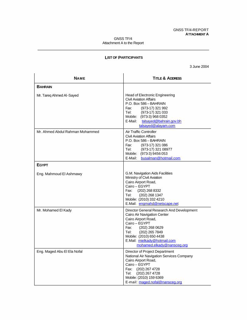
GNSS TF/4-REPORT ATTACHMENT A
GNSS TF/4 Attachment A to the Report
LIST OF PARTICIPANTS
3 June 2004
NAME TITLE & ADDRESS
BAHRAIN Mr. Tareq Ahmed Al -Sayed
Head of Electronic Engineering Civil Aviation Affairs P.O. Box 586 – BAHRAIN Fax: (973-17) 321 992 Tel: (973-17) 321 033 Mobile: (973-3) 968 0352 E-Mail: [email protected] [email protected]
Mr. Ahmed Abdul Rahman Mohammed Air Traffic Controller Civil Aviation Affairs P.O. Box 586 – BAHRAIN Fax: (973-17) 321 086 Tel: (973-17) 321 08977 Mobile: (973-3) 9456 053 E-Mail: [email protected]
EGYPT Eng. Mahmoud El Ashmawy
G.M. Navigation Aids Facilities Ministry of Civil Aviation Cairo Airport Road, Cairo – EGYPT Fax: (202) 268 8332 Tel: (202) 268 1347 Mobile: (2010) 332 4210 E.Mail: [email protected]
Mr. Mohamed El Kady
Director General Research And Development Cairo Air Navigation Center Cairo Airport Road, Cairo – EGYPT Fax: (202) 268 0629 Tel: (202) 265 7849 Mobile: (2010) 650 4438 E.Mail: [email protected] [email protected]
Eng. Maged Abu El Ela Nofal Director of Project Department National Air Navigation Services Company Cairo Airport Road, Cairo – EGYPT Fax: (202) 267 4728 Tel: (202) 267 4728 Mobile: (2010) 159 6369 E-mail: [email protected]

GNSS TF/4-REPORT ATTACHMENT A
A-2
NAME TITLE & ADDRESS
Mr. Mohamed Atef Ammar ATC Instructor Cairo Air Navigation Center Cairo Airport Road, Cairo – EGYPT Tel: (202) 265 7813 Mobile: (2010) 3392 748 E-mail: [email protected]
Mr. Mohsen El-Agaty Director of Research and Development National Air Navigation Services Company Cairo international Airport, Cairo – EGYPT Fax: (202) 267 4728 Tel: (202) 265 7839 Mobile: (2010) 162 3922
Mr. Ibrahim Melouk Cairo Acc - Director National Air Navigation Services Company Cairo international Airport, Cairo – EGYPT Fax: (202) 637 3950 Tel: (202) 265 7883 Mobile: (2010) 153 8780 E-mail: [email protected]
Eng. Farouk Ahmed Ragab Senior Advisor ECAA Ministry of Civil Aviation Cairo Airport Road, Cairo – EGYPT Fax: (202) 266 5435 Tel: (202) 267 7382 Mobile: (2010) 185 225
Mr. Metwally Mohamed Metwally ATS Instructor National Air Navigation Services Company Cairo international Airport, Cairo – EGYPT Fax: (202) 637 3950 Tel: (202) 265 7883 Mobile: (2010) 1255 851
Mr. Galal Ibrahim Satellite Director National Air Navigation Services Company Cairo international Airport, Cairo – EGYPT Tel: (202) 268 5279 Mobile: (2012) 717 3348 E.Mail: [email protected]
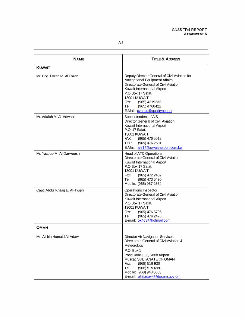
GNSS TF/4-REPORT ATTACHMENT A
A-3
NAME TITLE & ADDRESS
KUWAIT Mr. Eng. Fozan M. Al Fozan
Deputy Director General of Civil Aviation for Navigational Equipment Affairs Directorate General of Civil Aviation Kuwait International Airport P.O.Box 17 Safat, 13001 KUWAIT Fax: (965) 4319232 Tel: (965) 4760421 E.Mail: [email protected]
Mr. Adullah M. Al -Adwani Superintendent of AIS Director General of Civil Aviation Kuwait International Airport P.O. 17 Safat, 13001 KUWAIT FAX: (965) 476 5512 TEL: (965) 476 2531 E.Mail: [email protected]
Mr. Yacoub M. Al Darweesh Head of ATC Operations Directorate General of Civil Aviation Kuwait International Airport P.O.Box 17 Safat, 13001 KUWAIT Fax: (965) 472 2402 Tel: (965) 473 5490 Mobile: (965) 957 9364
Capt. Abdul Khaliq E. Al-Twijiri Operations Inspector Directorate General of Civil Aviation Kuwait International Airport P.O.Box 17 Safat, 13001 KUWAIT Fax: (965) 476 5796 Tel: (965) 474 2478 E-mail: [email protected]
OMAN Mr. Ali bin Humaid Al-Adawi
Director Air Navigation Services Directorate General of Civil Aviation & Meteorology P.O. Box 1 Post Code 111, Seeb Airport Muscat, SULTANATE OF OMAN Fax: (968) 519 930 Tel: (968) 519 699 Mobile: (968) 943 3003 E-mail: [email protected]
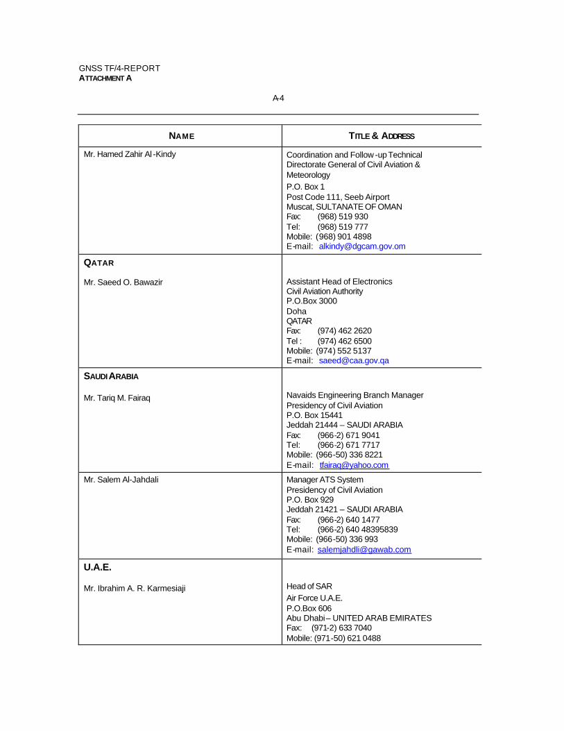
GNSS TF/4-REPORT ATTACHMENT A
A-4
NAME TITLE & ADDRESS
Mr. Hamed Zahir Al -Kindy Coordination and Follow -up Technical Directorate General of Civil Aviation & Meteorology P.O. Box 1 Post Code 111, Seeb Airport Muscat, SULTANATE OF OMAN Fax: (968) 519 930 Tel: (968) 519 777 Mobile: (968) 901 4898 E-mail: [email protected]
QATAR Mr. Saeed O. Bawazir
Assistant Head of Electronics Civil Aviation Authority P.O.Box 3000 Doha QATAR Fax: (974) 462 2620 Tel : (974) 462 6500 Mobile: (974) 552 5137 E-mail: [email protected]
SAUDI ARABIA Mr. Tariq M. Fairaq
Navaids Engineering Branch Manager Presidency of Civil Aviation P.O. Box 15441 Jeddah 21444 – SAUDI ARABIA Fax: (966-2) 671 9041 Tel: (966-2) 671 7717 Mobile: (966-50) 336 8221 E-mail: [email protected]
Mr. Salem Al-Jahdali
Manager ATS System Presidency of Civil Aviation P.O. Box 929 Jeddah 21421 – SAUDI ARABIA Fax: (966-2) 640 1477 Tel: (966-2) 640 48395839 Mobile: (966-50) 336 993 E-mail: [email protected]
U.A.E. Mr. Ibrahim A. R. Karmesiaji
Head of SAR Air Force U.A.E. P.O.Box 606 Abu Dhabi – UNITED ARAB EMIRATES Fax: (971-2) 633 7040 Mobile: (971-50) 621 0488
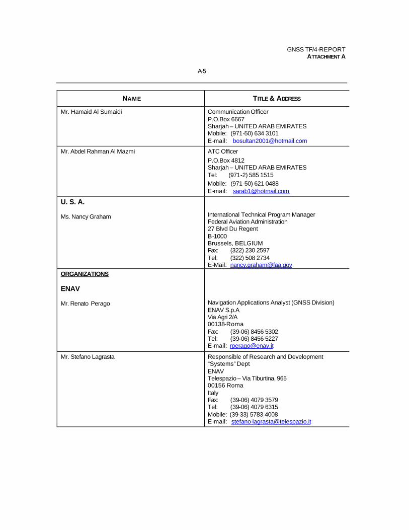
GNSS TF/4-REPORT ATTACHMENT A
A-5
NAME TITLE & ADDRESS
Mr. Hamaid Al Sumaidi Communication Officer P.O.Box 6667 Sharjah – UNITED ARAB EMIRATES Mobile: (971-50) 634 3101 E-mail: [email protected]
Mr. Abdel Rahman Al Mazmi ATC Officer P.O.Box 4812 Sharjah – UNITED ARAB EMIRATES Tel: (971-2) 585 1515 Mobile: (971-50) 621 0488 E-mail: [email protected]
U. S. A. Ms. Nancy Graham
International Technical Program Manager Federal Aviation Administration 27 Blvd Du Regent B-1000 Brussels, BELGIUM Fax: (322) 230 2597 Tel: (322) 508 2734 E-Mail: [email protected]
ORGANIZATIONS ENAV Mr. Renato Perago
Navigation Applications Analyst (GNSS Division) ENAV S.p.A Via Agri 2/A 00138-Roma Fax: (39-06) 8456 5302 Tel: (39-06) 8456 5227 E-mail: [email protected]
Mr. Stefano Lagrasta Responsible of Research and Development “Systems” Dept ENAV Telespazio – Via Tiburtina, 965 00156 Roma Italy Fax: (39-06) 4079 3579 Tel: (39-06) 4079 6315 Mobile: (39-33) 5783 4008 E-mail: [email protected]
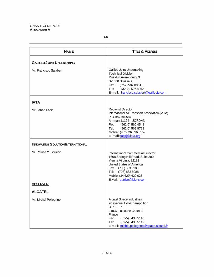
GNSS TF/4-REPORT ATTACHMENT A
A-6
NAME TITLE & ADDRESS
GALILEO JOINT UNDERTAKING Mr. Francisco Salabert
Galileo Joint Undertaking Technical Division Rue du Luxembourg. 3 B-1000 Brussels Fax: (32-2) 507 8001 Tel: (32-2) 507 8062 E-mail: [email protected]
IATA Mr. Jehad Faqir
Regional Director International Air Transport Association (IATA) P.O.Box 940587 Amman 11194 – JORDAN Fax: (962-6) 560 4548 Tel: (962-6) 569 8728 Mobile: (962-79) 596 6559 E- mail: [email protected]
INNOVATING SOLUTION INTERNATIONAL Mr. Patrice Y. Bouëdo
International Commercial Director 1608 Spring Hill Road, Suite 200 Vienna Virginia, 22182 United States of America Fax: (703) 883 9180 Tel: (703) 883 8088 Mobile: (34 629) 620 023 E.Mail: [email protected]
OBSERVER ALCATEL Mr. Michel Pellegrino
Alcatel Space Industries 26 avenue J.-F.-Champollion B.P. 1187 31037 Toulouse Cedex 1 France Fax: (33-5) 3435 5118 Tel: (39-5) 3435 5142 E-mail: [email protected]
- END -