international bureau 111111 11111111 11 111111 …(12) international application published under the...
TRANSCRIPT

(12) INTERNATIONAL APPLICATION PUBLISHED UNDER THE PATENT COOPERATION TREATY (PCT)
(19) World Intellectual Property Organization International Bureau 111111 11111111 11 111111 11111 11111 11111 1111 111 111 11111 11111 11111 11111 11111 1111 1111111 1111 1111 1111
(43) International Publication Date PCT (10) International Publication Number
15 March 2007 (15.03.2007) WO 20071029215 A2 (51) International Patent Classification: Not classified (81) Designated States (unless otherwise indicated, for every
kind of national protection available): AE, AG, AL, AM, (21) International Application Number: AT, AU, AZ, BA, BB, BG, BR, BW, BY, BZ, CA, CH, CN,
PCTAB20061053 192 CO, CR, CU, CZ, DE, DK, DM, DZ, EC, EE, EG, ES, FI, GB, GD, GE, GH, GM, HN, HR, HU, ID, IL, IN, IS, JP,
(22) International Filing Date: KE, KG, KM, KN, KP, KR, KZ, LA, LC, LK, LR, LS, LT,
8 September 2006 (08.09.2006) LU, LV, LY, MA, MD, MG, MK, MN, MW, MX, MY, MZ,
(25) Filing Language:
(26) Publication Language:
English NA, NG, NI, NO, NZ, OM, PG, PH, PL, PT, RO, RS, RU, SC, SD, SE, SG, SK, SL, SM, SV, SY, TJ, TM, TN, TR,
English TT, TZ, UA, UG, US, UZ, VC, VN, ZA, ZM, ZW.
(30) Priority Data: (84) Designated States (unless otherwise indicated, for every 601596,198 8 September 2005 (08.09.2005) US kind of regional protection available): ARIPO (BW, GH, 601721,731 28 September 2005 (28.09.2005) US GM, KE, LS, MW, MZ, NA, SD, SL, SZ, TZ, UG, ZM, 601597,162 14 November 2005 (14.1 1.2005) US ZW), Eurasian (AM, AZ, BY, KG, KZ, MD, RU, TJ, TM),
European (AT, BE, BG, CH, CY, CZ, DE, DK, EE, ES, FI, (71) Applicant (for all designated States except US): SPD FR, GB, GR, HU, IE, IS, IT, LT, LU, LV, MC, NL, PL, PT,
- - CONTROL SYSTEMS CORPORATION [USNS]; RO, SE, SI, SK, TR), OAPI (BF, BJ, CF, CG, CI, CM, GA, = - 25 Health Sciences Drive, Suite 212b, Stony Brook, NY = - GN, GQ, GW, ML, MR, NE, SN, TD, TG). = 1 1790 (US). = - - - (72) Inventor; and Published: - = - (75) InventorIApplicant (for US only): MOSKOWITZ, Jay
- without international search report and to be republished - - - - [USNS]; 12189 Landrum Way, Boynton Beach, F'L 33437- upon receipt of that report - - 6360 (US). = - - - For two-letter codes and other abbreviations, refer to the "Guid- = - (74) Agent: OPPEDAHL, Carl; Oppedahl & Olson LLP, P 0 ance Notes on Codes andAbbreviations"appearing at the begin- = - Box 4850, Frisco, CO 80443-4850 (US). = ning of each regular issue of the PCT Gazette. = = - = - (54) Title: INTELLIGENT SPD CONTROL APPARATUS WITH SCALABLE NETWORKING CAPABILITIES FOR WIN- - - - - DOW AND MULTIMEDIA APPLICATIONS - - -
- - - I - \ - - - = - = - CONTROLLER SPD
= - - - WINDOW - = = - - - (57) Abstract: A scalable apparatus and a network environment dynamically changes the light transparency of a single SPD device, -
a small number of SPD devices or thousands of such SPD devices installed in windows in automobiles, aircraft, trains, marine - - vehicles, residential homes, commercial buildings and skyscrapers. A scalable apparatus and a network environment dynamically
C\1 changes the light transparency of a single SPD device or thousands of such SPD devices in the presentation of a multi-media special 4 effects display. Textual messages, graphical images and simulated motion effects are driven. Such scalable apparatus being capable
of driving and using several operational parameters of SPD materials such as frequency range, AC voltage and temperature so as to provide fine control of SPD characteristics such as switching speed and power consumption.
H C\1 m C\1 0 \ b 0 0 C\1

WO 20071029215 PCTlIB20061053192
Intelligent SPD control apparatus with scalable networking
capabilities for window and multimedia applications
CROSS-REFERENCE TO RELATED APPLICATIONS
This application claims priority from US application numbers 601596,198 filed September 8,2005
and entitled "A scaleable system consisting of apparatus for controlling a single SPD device to a
plurality of such devices operating across a wireless mesh packet switched network," 60172 1,73 1
filed September 28,2005 and entitled "An Electronic Controller and Wireless Network for
Multi-media Video Displays using SPD Glass," and 601597,162 filed November 14,2005 and
entitled "A scaleable system for the control of solar heat in residential and commercial buildings
utilizing SPD-based windows," each of which is incorporated herein by reference for all purposes.
BACKGROUND OF THE INVENTION
Light valves have been in use for more than sixty years for the modulation of light. As used herein,
a light valve is defined as a cell formed of two walls that are spaced apart by a small distance, at
least one wall being transparent, the walls having electrodes thereon, usually in the form of
transparent, electrically conductive coatings. The cell contains a light-modulating element
(sometimes herein referred to as an "activatable material"), which may be either a liquid suspension
of particles, or a plastic film in which droplets of a liquid suspension of particles are distributed.
The liquid suspension (sometimes herein referred to as "a liquid light valve suspension" or "a light
valve suspension") comprises small, anisotropically shaped particles suspended in a liquid
suspending medium. In the absence of an applied electrical field, the particles in the liquid
suspension assume random positions due to Brownian movement, and hence a beam of light
passing into the cell is reflected, transmitted or absorbed, depending upon the cell structure, the
nature and concentration of the particles, and the energy content of the light. The light valve is thus
relatively dark in the OFF state. However, when an electric field is applied through the liquid light
valve suspension in the light valve, the particles become aligned and for many suspensions most of
the light can pass through the cell. The light valve is thus relatively transparent in the ON state.
Light valves of the type described herein are also known as "suspended particle devices" or "SPDs."
More generally, the term suspended particle device, as used herein, refers to any device in which
suspended particles align to allow light to pass through the device when an electric field is applied.
Light valves have been proposed for use in numerous applications including windows, skylights,
and sunroofs, to control the amount of light passing therethrough or reflected therefrom as the case
may be. As used herein the term "light" generally refers to visible electromagnetic radiation, but
where applicable, "light" can also comprise other types of electromagnetic radiation such as, but not
limited to, infrared radiation and ultraviolet radiation.
The SPD is laminated between two pieces of glass or plastic and becomes an internal layer. Such a
combination is sometimes referenced as an SPD-Film.
Such SPDs are now being installed into glass so that the amount of light passing through the glass
can be finely controlled based upon the characteristics of the electricity passing through the glass.
At least one method by which such glass and thus its opacity or light transparency may be
controlled is described by Malvino, in U.S. Patent No. 6,897,997 and 6,804,040 collectively
referred to as the Malvino patents. But a device envisioned by Malvino, while suitable for the
manual control of an environment of a few windows, is not scalable or nor does it provide the
automated intelligence to actively and dynamically control environments of more than a few
windows such as in an automobile, marine vehicle, train or aircraft, to as much as a residential or
commercial building or a skyscraper of such SPD windows.
The Malvino patents provide the basis for driving SPD glass by varying at a fixed frequency which
will cause the glass to lighten toward clear or to darken so as to block most light passing through it.
That device is capable of mapping the non-linear characteristics of SPD into a linear range of values
that could be thought of as setting the glass from say 0 to 100%. The range is broken down into a
small discrete set of settings for perhaps 6 different opaqueness levels and 6 specific resistor and
capacitor combinations are built into the implementation and are manually selected to set the proper
voltage for the associated degree of tinting. Through that implementation, a linear manual control,
such as a slide switch or a rotating dial may be attached to the Malvino controller to directly vary
the amount of light allowed through the glass at any time.
The Malvino Patents reviews the use of a few fixed frequencies at which to drive an SPD Device.
As described, driving the device at a lower frequency tends to have a slight lower energy utilization
curve with regard to the power needed to drive the SPD Device. Frequencies in the range of 15
hertz to 60 hertz were discussed. There is a serious potential problem with the aforementioned SPD

WO 20071029215 PCTlIB20061053192
Controller when driven by these frequencies. It is possible that the SPD device will "sing" and be
heard as a tone in the B-flat range by being driven by a fixed frequency within that range. An SPD
controlled window typically consists of SPD-capable material in the form of a clear Mylar coated
with SPD emulation, placed in between two pieces of glass. The SPD device is basically
sandwiched and held in place by glass on both sides. If 50160 Hertz current travels through the
sandwiched SPD material, in some cases, the Mylar will start to vibrate in resonance with the
driving frequency and may be heard by people near the window as an annoying hum.
A considerable issue in the wide-scale worldwide deployment of SPD windows, is on how
residential and commercial buildings will be wired up to allow some "central intelligence" to
operate the individual windows. Today, there is no concept of running wires to windows from some
control room in the building. It is not desirable to introduce a new requirement for building wiring
in the introduction of SPD glass around the world, since thousands of installation people would
need to learn and understand new building wiring requirements. Yet, if any other techniques are
employed to "wire" each window to the "central intelligence", it must require little or no training,
and be a relatively low cost so as not to make the use of SPD glass prohibitive.
SUMMARY OF THE INVENTION
The invention relates to a wirelessly enabled apparatus and associated mesh networking software
installed in large arrays in order to dynamically control the "skin" of residential and commercial
buildings throughout the day in order to absorb or reflect sunlight in such a manner as to
dramatically reduce the energy consumption of such buildings. The integration of a mesh network
lowers the cost of deployment of such control by permitting the individual devices that control one
or more windows, to act as a relay point in moving control signals from intelligent control points in
a Building Skin Control System to the individual controllers or sets of controllers which will effect
the desired changes. The invention further relates to a Suspended Particle Device control apparatus
and associated network installed in large arrays in order to dynamically control the glass windows
of residential and commercial buildings throughout the day in order to absorb or reflect sunlight in
such a manner as to dramatically reduce the energy consumption of such buildings. The use of a
hierarchical distribution system over a LAN or WAN reduces the time to transmit commands from
a central intelligence point, the Master Control Point, to all window controllers in a structure to set
individual windows to a specific level of opaqueness.

WO 20071029215 PCTlIB20061053192
The device described herein corrects for the "singing" problem by providing the option of driving
the SPD Device at a variable frequency in the low frequency range rather than a single fixed
frequency. Optionally, in lieu of using a continuously variable SPD driving frequency, the
Controller may randomly drop or phase shift several cycles per second. The changelshift is not
enough to be visibly noticeable but it would eliminate the "ringing effect". As will be seen below,
the system according to the invention scales from the single-window environment to a building with
a size beyond that of the currently largest in the world, the Petronas Towers in Kuala Lampw, with
32,000 windows.
This invention provides for a range of SPD control far beyond that previously in existence. The
"Scalable Controller" a.k.a. "SC" of this invention adds intelligence that greatly expands the
capabilities of prior controllers. As in prior implementations, one to several pieces of glass may be
controlled by a single controller, where several is a relatively small number such as 8 and each
piece of glass is hardwired to the controller. The Scalable controller further supports a setup phase
whereby the user may configure the relationship between manual external control or several
individual manual controls and which windowlwindows are to be controlled from that manual
setting. In a setting of fow windows under the Scalable Controller, where the windows are referred
to as A, B, C and D, a user may configure the SC so that windows AB are controlled as a single
window and CD as another, or ABC is controlled as a single window and D as another, or ABCD is
controlled as a single window or, A B C D are controlled as 4 separate windows.
This system coordinates the settings of each of the windows in a building in an intelligent manner
from a central intelligence point known of the Master Building Control Point. It will make
intelligent decisions based on many factors including real time events, as to the proper amount of
visible light to permit to flow through each window in order to take best advantage of the solar
heating effect.
Enhanced capabilities of the SC over prior inventions provide for full control of all operational
parameters which effect the characteristics of a SPD. This type of control exists in each SC to
optimize SPD performance by power utilization or switching speed potentially taking into account
external temperatwe, while controlling the haze and clarity.
The flexibility of the SC and its networking capabilities also support the display of textual messages
or special light tinting sequences as part of a multimedia presentation. Such a multimedia display

WO 20071029215 PCTlIB20061053192
could change windows along the faqade of an office building in time to the changes in perhaps
Christmas Music during the holiday period. A scaled-down version of such a system could provide
for a moving textual display across small SPD pixels sitting in a box on a desktop. These diverse
applications reflect the flexibility and importance of this invention.
BRIEF DESCRIPTION OF THE DRAWING
The invention will be described with respect to a drawing in several figures, of which:
FIG. 1 is a diagram showing an SPD window controller under manual adjustment from a
single external device.
FIG. 2 is the controller of Figure 1 with the addition of a photocell or other photosensor to
detect the brightness of sunlight shining on the window under control.
FIG. 3 creates the Intelligent Controller by introducing a microprocessor to perform a
number of different functions in support of more sophisticated controller capabilities as well
as Scalable Network operation of controllers. Additional inputs from sensors expand the
data which the Scalable controller may use to make decisions.
FIG. 4 shows the Intelligent Controller with a plurality of manual inputs that are coupled to
one or several window panes that are under the direct control of the controller as set up by
the user via a set up procedure in the control software. A single manual input may control
one window or, two, three or four at one time as if it were a single piece of SPD glass. More
then one manual input may be used to control the same set of glass in order to support
manual controls that operate from different points in the same room.
FIG. 5 shows different combinations of four-window panes in this example, and how the set
up software allows any combination of sets of individual panes to be treated as a single pane
of glass.
FIG. 6 shows one of the earliest packet switching or mesh networks in which data may be
sent along alternate paths through intermediate nodes in order to reach a destination point.
This is an example of the 4-node Arpanet in 1969, the precursor to today's Internet. Host
computers sent data to other Host computers in this network and utilized the services of the
Interface Message Processor (IMP) to move data packets to other IMP'S which were not
destination point but would further relay packets toward the IMP directly connected to the
desired destination Host.
FIG. 7 shows a more advanced packet switched meshed network in which specific
WO 20071029215 PCTlIB20061053192
processing applications operate on the same computer that is running the packet switching
software thereby combining the functions of Hosts and IMPS in the earlier Arpanet systems.
Increases in microprocessor power allowed these functions to be combined onto a single
platform. This is an example of a Radio Paging Network application utilizing the DLH
protocol created by the Inventor to convert isolated Citywide radio paging (beeper) systems
into a nationwide network capable of alerting someone wherever they are located in the
country instead of just a single city. The Arpanet and Internet utilize formalized routing
protocol specifications such as RIP to dynamically maintain a list of best routes to a
destination at each node. DLH utilizes a proprietary routing protocol to maintain a list of
primary and alternate routes. The proprietary DLH network was eventually replaced with
the Radio Paging Industry standard TNPP protocol which the Inventor helped to create and
Chaired the Industry committee to promote the use of this protocol for more than 1 1 years.
TNPP was used along with a manufacturer-specific proprietary routing protocol to maintain
the best and alternate paths to each destination node.
FIG. 8 shows a Scalable Controller network consisting of the Intelligence Controller of
Figure 3 integrated with a radio transceiver to send packets of data to other transceiver
equipped Scalable Controller nodes. Routing data similar to the Internet RIP, maintains a list
at each Controller node of the best next node to receive data on the path to the destination
node. Unlike the wired network of Figures 6 and 7, the radio network of Figure 8 may
sometimes properly receive data addressed to a different node than that which received it. In
this case, the received data is ignoredldropped by the node which is not the next node along
the optimal path to the destination.
FIG. 9 shows an example of a network of Figure 8 where a Building Control Point is
connected to one of the nodes of the network. The BCP is a data processing site to
determine which portions of a building are to be automatically set to a specific opacity at
any moment of the day or night. The Data Processing system may optionally be connected
to the Internet and to a remote central monitoring service which oversees the operations of
the SPD Building Skin Control System on behalf of many building owners.
FIG. 10 shows an example of a redundant Building Control Point (BCP) supported in the
network to insure that the entire system continues to operate normally even if the primary
BCP should fail.
FIG. 1 1 shows how different areas of a building would have different types of Hierarchical
Control Points to oversee the operation of Scalable Controllers in certain portions of a
building.
WO 20071029215 PCTlIB20061053192
FIG. 12 is a Hierarchical mapping of Control Points showing how commands generated at
the highest level Control Point are logically distributed to lower level Control Points that
distribute the commands to more and more elements at lower hierarchy levels.
FIG. 13 shows how the Building Control Point interfaces with an Intelligent Energy Control
System (IECS) via an XML interface.
FIG. 14 shows how the path of the Sun across the sky changes how the sunlight falls on the
windows of a building throughout the day. The Sun path changes slightly each day of the
year as the Earth rotates around the Sun. For any latitude and longitude on the planet, the
path that is traversed is well known.
FIG. 15 shows five controllers each controlling sixteen panes.
FIG. 16 shows the letter "E" formed by a 5 by 7 pixel array with a border.
FIG. 17 shows a lighting effect in which each pane differs from its neighbor by a few
percent.
FIG. 18 shows a controller sending a command to a decoder which in turn communicates
commands to windows.
FIG. 19 shows two Scalable Controllers (SCs) consisting of the Intelligent Controller of
Figure 1 integrated with a LAN interface so that they can send packets of data to a Master
Control Point (MCP) located on the LAN.
FIG. 20 shows that when LANs has reached its maximum capacity, due to cable length, a
Bridge may be introduced in order to add another LAN segment to extend the size of the
LAN.
FIG. 2 1 shows how to further extend the size of a local network when the maximum number
of LAN segments and BridgeRepeaters has been deployed.
FIG. 22 shows the logical connections that form a hierarchy of control points in order to
reduce the point to point communication loading on the MCP to issue commands to all SCs
in a building.
FIG. 23 shows how the Master Control Point, which provides the central control intelligence
for all of the individual windows in a structure, can connect to an external Intelligent Energy
Control System via an XML link. The external system can modify its operations knowing
where windows have been changed. The external system may receive sensor input through
the MCP and may command the MCP to modify the setting or some or all windows under
its control. The MCP also has the option of changing the operation of the windows under
IECS command if better algorithms have been developed on the IECS and the External
system starts sending the proper control commands..

WO 20071029215 PCTlIB20061053192
FIG 24 shows the major subsections which comprise the Scalable Controller.
FIG 25 shows one of the typical three-dimensional tables of data that is programmed into
the controller to operate it. Such table provide information on the interaction of three
variables that together control the operation of SPD based glass.
DETAILED DESCRIPTION OF THE INVENTION
With the incorporation of a Microprocessor into the Scalable Controller, the capabilities and
flexibility of the device are expanded dramatically for use both in a standalone environment as well
as being a data point in a sea of such controllers which, under such intelligent control, can
dynamically modify the skin of an office building to provide unprecedented control over its energy
usage. Even in the standalone environment, the SC can be programmed with the intelligence to
reduce energy usage in the room where it is being used. The SC may be put into an automatic mode
instead of being under manual control and can operate as described below.
Although the same functions may be achieved in several ways, in the implementation described
herein, the end user has the ability to set the latitude, longitude, window orientation from North, and
window angle from vertical into a suitable data processing program. This program creates a profile
that can be downloaded into the SC which uses the setup data to determine the location on the earth
of the window(s) under control and thereby, for each window, its angle from the sun at any time of
the day. A timeldate clock operates in the SC to drive its window(s) based upon the time of day, day
of year, and the location on the planet. At 1 :00 PM on July 2nd in Manhattan, New York, the
windows directly facing the sun would be set to the maximum opaqueness while those angled away
from the sun would have reduced opaqueness and those on the opposite side of the building might
be totally clear. As the sun crosses the sky, each window changes according to the built-in profile.
Yet at 1 :00 PM on July 2nd in Sydney Australia, those windows facing the sun will be clear, so that
the building's heating system requirements may be reduced by utilizing the sun to heat windows
directly facing the sun, while windows on the opposite side of the building would be turned dark so
as to keep heat trapped in the building. A photocell connected to the SC will provide external sensor
input so as to allow the SC to further fine tune the current opaqueness based upon current cloud and
weather conditions. Sidereal information has been well known and calculable for centuries and may
thus be profiled into the SC device itself. Weather conditions that might block the sun are random
real-time events.

WO 20071029215 PCTlIB20061053192
Although such Intelligent control permits several windows to operate autonomously, in a larger-
scale implementation, it is desirable to put entire segments of building windows under a coordinated
set of controls. In relatively large types of environments, rather than using a profile of individual
windows, it is possible to perform more real-time data processing and to make more intelligent
decisions of the opacity of every segment of a building at any point in time. The SC of this
invention is capable of expanding so as to operate in such a mode.
This system virtually eliminates all building wiring issues to put all SPD windows under a central
control. Each Scalable Controller is outfitted with a low-power, low-data-rate, limited-range, radio
transceiver. These radio transceivers are capable of communicating on a point-to-point basis to one
or more radio transceivers located within other Scalable Controllers in a 3-dimensional space
around each controller . The SC microprocessor is further outfitted with mesh networking software.
Such types of software have been in existence in various incarnations for a long period of time. The
radio transceivers send specially formatted packets of data back and forth between each other. Some
packets contain data which is used to operate the mesh network itself while other packets contain
sensor data or window control information. Routing control packets are one type of mesh control
packet which is sent. Each SC can be thought of as a "node" in the mesh network. The routing
information is used to leave information at each individual node to indicate an available "route" to
move data from a window controller to another intermediate window controller along a path to a
"Hierarchical Control Point (HCP)" or from an HCP through intermediate window controllers on its
way to a specific individual window controller. An HCP is the location of a special data processing
node, as opposed to a window controller node, which is capable of coordinating the changing of the
opaqueness of windows for some segment of a building. There may be several Office Control
Points (OCP), Section Control Points (SCP), Region Control Points (RCP), Floor Control Points
(FCP), Multi-floor Control Points (MCP) and a single Building Control Point (BCP) located in
typical building environment. A single Control Point might exist in a small implementation while
all types of Control Points may exist in a very large-scale implementation. The use of additional
Control Points reduces communication overhead in the mesh network and decreases the time delay
between the time a window opaqueness modification command is sent and when it is acted upon at
individual windows. In this instantiation of the invention, any window SC can become a Control
Point via a command sent from the Building Control Point. Although a Building Control Point is an
Intelligent Data Processing System, the lower hierarchical control points have a relatively small set
of fixed commands and operations which can easily be handled at the Microprocessor at any
window SC. In the largest-scale implementation of the Scalable Controller Network, the BCP can

WO 20071029215 PCTlIB20061053192
inform the Multi-Floor Control Points (MCP) to change the settings of each window on all floors;
the MCP will distribute this request to each of the FCP's; the FCP's will distribute the request to
the RCP's; the RCP's will send the command to SCP's; and the SCP's will forward the commands
to OCP's which will command each window controller in an office to execute the required change.
Because of the expansion to multiple nodes at each level of the hierarchy, commands may be
simultaneously sent within different non-overlapping areas of the network where they may pass
through intermediate nodes with no or little queuing delay, thus having the request executed
throughout the building in a seemingly simultaneous fashion.
Typically, a window controller is not in direct radio communication with the location in the
building where a HCP might be located. But every window controller will typically be within radio
communication of several other window controllers. The mesh networking software permits a data
packet to be sent from a source node to any neighboring node that is along a path which eventually
leads to the destination node, through a series of hops through intermediate nodes. Because of the
multiple paths that exist between nodes, data can typically be routed around areas of the network
that might be temporarily undergoing radio interference. Data retransmission and acknowledgments
during point-to-point communications insure that data is not dropped by one node until the next
node in the network has accepted the data being sent. If such acknowledgment is not received, a
node may send its data onto an alternate path to the destination. If a segment of the radio network
should become isolated, a packet hop count insures that packets which will never reach their
ultimate destination are eliminated from the network. End-to-end acknowledgments let the source
and destination nodes recognize when data must be retransmitted in its entirety because it may have
been dropped due to a particular radio failure creating isolated subnetworks. Reporting processes
built into the Building Controller monitor the nodes in the network, gather interconnectivity data,
and take into account the window controller addresses to assist the installer in insuring that all
nodes are capable of communicating with the Hierarchical Control Points. Where it might be found
that some portion of the overall network is isolated from another portion, special nodes may be
installed in a geographical area between existing segments of the network, in order to provide a
bridging point for data to move from one network segment toward the other. There should typically
be at least two nodes to bridge isolated segments together. The bridges are nothing more than
window Scalable Controllers that are not connected to any SPD window.
The Scalable Controllers may be equipped with various types of sensors that may be used in more
finely controlling the energy usage in a building. A photocell may be placed onto each SPD glass

WO 20071029215 PCTlIB20061053192
and connected to its SC. The Building Control Point "BCP" may command all the SCs to
periodically send sensor data to the BCP or the BCP may periodically poll each of the SCs to read
photocell and other sensor data. Through an initial system configuration procedure at the BCP, it is
made aware of the configuration of the building, the compass direction in which windows face, the
latitude and longitude of the building, the angle at which each window is from the vertical, and the
location of unique node and window addresses. Input from photocells throughout the building allow
the BCP to utilize voting techniques to determine the best areas of the building in which to increase
or decrease opaqueness in order to reduce the overall building energy requirements for heating and
air conditioning. If a readable compass and glass angle detector is installed at each SC, the process
of modeling the building to establish more precise control of each window, is simplified, by directly
providing this configuration information.
The BCP allows the system operator to establish special overrides for portions of the building at
certain times of the day and days of the year. This might be utilized to specify a region of the
building undergoing glare from reflections from other buildings or natural features in the area. The
override features would allow a normally clear window to perhaps to be darkened for some period
to eliminate the glare onto that portion of the building. So some regions of a building might be
under automatic control while other segments of the building may be under special override
conditions at the time. A complex combination of each control may be in effect at one time.
Many "Green" buildings already incorporate an Intelligent Energy Control System such as the
Honeywell Enterprise Buildings Integrator (EBI). These types of systems operate/monitor/control
the building HVAC system, circulation of fresh air, elimination of building odors, control of electric
usage, and reduction of energy requirements to unoccupied areas. These top-of-the-line systems
also incorporate building security, monitoring and access control, asset tracking, fire and smoke
detection and even control fire doors and public announcement systems. This invention extends the
capabilities of these sophisticated systems in a manner that was never possible before. These system
may now effectively control the skin of the building dynamically during the day, optimizing the use
of the sun along with the movement of heat and air conditioning around the building. The
combination of both systems provides a level of efficiency of an even higher level than that capable
of standalone windows or BCP controlled windows, since it directly control multiple subsystems in
a building in a coordinated fashion.
In this instantiation of the invention, the BCP will provide an XML interface to an external system
WO 20071029215 PCTlIB20061053192
to provide additional sensor data to the external system and to allow the external system to request
adjustments to light levels around the building in a high-level form. The BCP takes requests from
the XML link, interprets them and executes them by sending the proper commands through the
hierarchical network to effect the changes requested by the external Intelligent Energy Control
System (IECS). When operating in this mode, the automated controls of the BCP are bypassed. A
periodic "heartbeat" transfer of XML command/responses over the BCPIIECS link insures that the
two systems remain in sync and that they coordinate operations. In the event the heartbeat is lost,
the BCP can fall back to its automated mode and operate the building independently until the IECS
system comes back on-line.
This invention utilizes low-cost, low-power, limited-range Radio Transceivers co-located with each
window controller device, to form a large scale wireless network between all of the windows in a
residential or commercial building. Windows are typically within 10 meters of each other within
buildings, so limited range transceivers are perfectly suited for this environment. The
microprocessor-driven software within each controller operates the local application functions of
the controller while at the same time executing radio packet switching type software used to send
messages from source nodes to destination nodes in a building, even though the source and
destination node are not in direct communication with each other because of their distance from
each other. The data which are to be moved from the source to the destination are sent to a
transceiver which is reachable from the source node, and toward another radio transceiver that is
reachable along a path which will eventually get the packetized data to the desired destination.
The technique of moving messages from source computers to destination computers through
intermediate points in a multiply-connected array of computers was originally referred to as Packet
Switching and was first characterized in the Arpanet, the precursor to the Internet in 1969. Figure
6, which represents the Arpanet's 4-node network operational in December 1969, could potentially
send a packet of data from Host 16 1 to Host 163, by handing the data packet to Interface Message
Processor (IMP) 61, which might forward it to IMP 62, and to IMP 63 where it is handed to
destination Host 163. If IMP 62 finds that the link to IMP 63 is not functioning for some period of
time, the same data from Host 16 1 to 163 could be handed over to IMP 64 to forward the data to
IMP 63 instead of using the failed direct link. The concept in a packet-switched network is to locate
alternate paths to get the packet to the ultimate destination point even if some individual
communication paths are out of service. Some packet networks utilize fixed routing tables to define
alternate data paths in the event of link failures and have algorithms to determine when primary or
WO 20071029215 PCTlIB20061053192
alternate paths are to be utilized. Other packet networks have dynamically updated routing
information that is periodically updated between adjacent nodes in order to continually maintain a
list of the best route to any ultimate destination in the network.
With improvements in hardware and software, the separation of a Host (applications processor) and
a packet switching network of nodes (the Interface Message Processors - IMP'S) was no longer
necessary. The 1980 ITT-DTS Faxpak facsimile Store-and-Forward packet switching system
integrated an application which provided compatibility between different speed fax machines of the
time, with a message passing network which allowed messages to always be delivered locally
instead of via what (in those days) were more expensive calls over long-distance lines. The Wide
Area Paging network in Figure 7 ran an application that permitted any node in the network to accept
a paging message (phone number) specified through a dial-in telephone call, a text message
received from an operator, or a message received from a remote node, to a paging message that
would be encoded and transmitted at a destination node. The packet switching software that
operated at the same nodes, directed paging application packets to be dropped off at the proper
destination node or nodes to page a person in multiple cities.
Packet networks typically operated with dedicated communication circuits between nodes in
different cities. More recently, the same multi-path packet switching technique has been deployed
into networks of radio transceivers, utilizing radio links in lieu of wired links between pairs of
nodes. These radio packet switching systems have become known as mesh networks. Unlike the
2-D wired communication circuits as in Figure 7, the radio devices in a mesh network permit
point-to-point communications within a 3-D region of each node. In an office environment, where
each window may represent a node, windows within a few feet left or right of a particular window
can be thought of as potential intermediate nodes, as well as windows that are potentially a few
floors above or a few floors below a particular window.
In this instantiation, a header packet in each transmission packet specifies the source node address,
destination node address and the address of the next hopping point along the path to the destination.
This data is transmitted in three dimensions when it is time for this Smart Controller to transmit
information to another point in the network. Many receivers will detect interference in the data they
receive, and will ignore the received data. Several other receivers may receive the packet but with
transmission errors. Only the node to which the correctly received packet is addressed will keep the
packet, analyze it and will decide if the data item is to be forward toward another intermediate node
WO 20071029215 PCTlIB20061053192
to the final destination or if the packet is to be handled by the application software at this node.
To allow multiple commands to be outstanding and be executed at different points in the network
simultaneously, a logical hierarchical structure is introduced into the network. Certain network
nodes are designated as Hierarchical Control Points (HCP) that only forward data toward lower
level Hierarchical Control Points. Ultimately, the lowest level HCP logically forwards data only to
a subset of all Scalable Controllers in the network. This logical configuration allows a single
command to be branched out in multiple commands and each of those commands to further expand
to even more multiple commands, thereby controlling the maximum number of nodes with the
minimal number of control messages at the highest level. So a command to make all windows clear
in a segment of a building would be initiated at the highest level node and be handed down to lower
levels nodes that understood where this command needs to be sent in order to effect the desired
windows in the building.
On the other hand, sensor data that was considered as an urgent data item to which to reach,
captured at the individual Scalable Controllers, would be directed to higher and then higher levels
of HCPs until the data item reaches the highest level HCP.
Turning to Fig. 1, we see an SPD window controller 2 under manual adjustment from a single
external device 1. It controls a window 5.
Fig. 2 shows the controller of Figure 1 with the addition of a photocell 10 to detect the brightness of
sunlight shining on the window 5 under control.
Fig. 3 creates the Intelligent Controller by introducing a microprocessor 3 to perform a number of
different functions in support of more sophisticated controller capabilities as well as Scalable
Network operation of controllers. Additional inputs from sensors 8 expand the data which the
Scalable controller may use to make decisions.
Fig. 4 shows the Intelligent Controller with a plurality of manual inputs 1 that are coupled to one or
several window panes 5 1-54 that are under the direct control of the controller as set up by the user
via a set up procedure in the control software. A single manual input may control one window or,
two, three or four at one time as if it were a single piece of SPD glass. More then one manual input
may be used to control the same set of glass in order to support manual controls that operate from

WO 20071029215
different points in the same room.
Fig. 5 shows different combinations of four-window panes in this example, and how the set up
software allows any combination of sets of individual panes to be treated as a single pane of glass.
In a setting of four windows under the Scalable Controller, where the windows are referred to as A,
B, C and D, a user may configure the SC so that windows AC are controlled as a single window and
BD as another, or BCD is controlled as a single window and A as another, or ABCD is controlled as
a single window or, A, B, C, D, are controlled as four separate windows.
Fig. 6 shows one of the earliest packet switching or mesh networks in which data may be sent along
alternate paths through intermediate nodes in order to reach a destination point. This is an example
of the 4-node Arpanet in 1969, the precursor to today's Internet. Host computers sent data to other
Host computers in this network and utilized the services of the Interface Message Processor (IMP)
61 to move data packets to other IMPs 62, 64 which were not destination points but would further
relay packets toward the particular IMP 63 directly connected to the desired destination Host 163.
Fig. 7 shows a more advanced packet switched meshed network in which specific processing
applications operate on the same computer that is running the packet switching software thereby
combining the functions of Hosts and IMPs in the earlier Arpanet systems. Increases in
microprocessor power allowed these functions to be combined onto a single platform. This is an
example of a Radio Paging Network application utilizing the DLH protocol created by the Inventor
to convert isolated Citywide radio paging (beeper) systems into a nationwide network capable of
alerting someone wherever they are located in the country instead of just a single city. The Arpanet
and Internet utilize formalized routing protocol specifications such as RIP to dynamically maintain
a list of best routes to a destination at each node. DLH utilizes a proprietary routing protocol to
maintain a list of primary and alternate routes. The proprietary DLH network was eventually
replaced with the Radio Paging Industry standard TNPP protocol which the Inventor helped to
create and Chaired the Industry committee to promote the use of this protocol for more than 1 1
years. TNPP was used along with a manufacturer-specific proprietary routing protocol to maintain
the best and alternate paths to each destination node. A paging message originating at node B 72
might be passed to other nodes 73,74 until reaching a node 7 1 which is in turn coupled with
antennas which pass information to a pocket pager receiver 17 1.
Fig. 8 shows a Scalable Controller network consisting of the Intelligent Controller of Figure 3
WO 20071029215 PCTlIB20061053192
integrated with a radio transceiver to send packets of data to other transceiver equipped Scalable
Controller nodes. Routing data similar to the Internet RIP, maintains a list at each Controller node
of the best next node to receive data on the path to the destination node. Unlike the wired network
of Figures 6 and 7, the radio network of Figure 8 may sometimes properly receive data addressed to
a different node than that which received it. In this case, the received data is ignoredldropped by the
node which is not the next node along the optimal path to the destination. Each controller 8 1, 82,
83, 84 has a controller, a microprocessor, and a radio transceiver.
Fig. 9 shows an example of a network of Figure 8 where a Master Building Control Point (MBCP)
90 is connected to one of the nodes of the network. The MBCP 90 is a data processing site to
determine which portions of a building are to be automatically set to a specific opacity at any
moment of the day or night. The Data Processing system may optionally be connected to the
Internet 9 1 and to a remote central monitoring service 92 which oversees the operations of the SPD
Building Skin Control System on behalf of many building owners.
Fig. 10 shows an example of a redundant Master Building Control Point (BCP) supported in the
network to insure that the entire system continues to operate normally even if the primary MBCP
should fail. One MBCP (shown as a data processor) is connected to node 8 1 and a second MBCP
(also shown as a data processor) is connected to a node 87.
Fig. 1 1 shows how different areas of a building would have different types of Hierarchical Control
Points (HCPs) to oversee the operation of Scalable Controllers in certain portions of a building.
Fig. 12 is a Hierarchical mapping of Control Points showing how commands generated at the
highest level Control Point are logically distributed to lower level Control Points that distribute the
commands to more and more elements at lower hierarchy levels. There may be several Office
Control Points (OCP), Section Control Points (SCP), Region Control Points (RCP), Floor Control
Points (FCP), Multi-floor Control Points (MCP) and a single Building Control Point (BCP) located
in typical building environment. A single Control Point might exist in a small implementation while
all types of Control Points may exist in a very large-scale implementation. The use of additional
Control Points reduces communication overhead in the mesh network and decreases the time delay
between the time a window opaqueness modification command is sent and when it is acted upon at
individual windows. In this instantiation of the invention, any window SC can become a Control
Point via a command sent from the Master Building Control Point. Although a Master Building
WO 20071029215 PCTlIB20061053192
Control Point is an Intelligent Data Processing System, the lower hierarchical control points have a
relatively small set of fixed commands and operations which can easily be handled at the
Microprocessor at any window SC. In an intermediate size implementation of the Scalable
Controller Network, the MBCP can inform the FCPs 96,99; the FCPs will distribute the request to
the RCPs 97, 100, 101, 102; the RCPs will send the command to OCPs which will command each
window controller in an office (not shown for clarity) to execute the required change. Because of
the expansion to multiple nodes at each level of the hierarchy, commands may be simultaneously
sent within different non-overlapping areas of the network where they may pass through
intermediate nodes with no or little queuing delay, thus having the request executed throughout the
building in a seemingly simultaneous fashion.
Fig. 22 shows the logical connections that form a hierarchy of control points in order to reduce the
point-to-point communication loading on the Multi-Floor Control Point MCP to issue commands to
all SCs in a building. In the example shown, the MCP sends commands to two Floor Control Points
(FCP) that are optimally placed on separate LANs. Simultaneously, each FCP can relay the
command to Section Control Points (SCP) that in turn may transmit the commands to Office
Control Points (OCP). Each OCP may simultaneously relay the commands it has received to the
one or more SCs for which it is responsible. Ultimately all of the SCs will have received the
required commands, but the hierarchical structure reduces the total number of data transmissions
across the entire network to reach each SC from the MCP.
Fig. 13 shows how the Master Building Control Point 1 10 interfaces with an Intelligent Energy
Control System (IECS) 1 1 1 via an XML interface 1 12. Fig. 23 shows in more detail how the
Master Building Control Point 204, which provides the central control intelligence for all of the
individual windows in a structure, can connect to an external Intelligent Energy Control System 2 10
via an XML link 209, so that the external system may receive sensor input through the MBCP and
may command the MBCP to modify the setting or some or all windows under its control.
Fig. 14 shows how the path of the Sun across the sky changes how the sunlight falls on the
windows of a building throughout the day. The Sun path changes slightly each day of the year as
the Earth rotates around the Sun. For any latitude and longitude on the planet, the path that is
traversed is well known.
Another embodiment of the invention transforms an array of windows into a part of a multi-media

WO 20071029215 PCTlIB20061053192
display. Office buildings are often decorated in a manner as to enhance the appearance of the city in
which it is located. In Houston, for example, many of the large buildings are outlined in rows of
small lights on the perimeter of each building so as to form an outline of the cities skyline each
evening. During holidays, many buildings will turn specific lights on and off in the building late at
night when the building is primarily empty so as to display some pattern associated with the
holiday. For example, during Christmas, a cross may appear in the windows of a large building. Or
diamond shape patterns may be displayed at different floor levels of a building and at adjacent
buildings as part of the winter season.
This embodiment extends the MBCP functions so that it may direct SPD windows to be part of a
video presentation. The controllers are unaffected when adding this capability because they already
have the ability to change any pane of glass under their control to any setting from clear to dark or
any setting in between under manual or under automated control from the MBCP. So a special,
non-energy-efficiency-related application may exist in the MBCP to operate the windows in a
special manner as desired by the building operator.
Textual Messaging Mode
There are two modes of operation, although they may both operate simultaneously. The first mode
is to use SPD windows to form a textual display of messages. In its simplest application each pane
of SPD glass represents a single pixel of information. The size of the window pane and the matrix
size making up a letter defines how far away the user must be from the window to be able to clearly
read the letters formed. In some cases a square box of 4 or 9 (2 x 2 or 3 x 3) windows may be
controlled as one in order to increase the size of an individual pixel. Each controller receives a
command from the MBCP to set its pixel to on or off or at some degree of shading. Using a set of
48 windows, a 6 x 8 pixel array may form any letter or punctuation and include a one-pixel border
around each letter.
The MBCP may operate in another mode where the message(s) to be displayed is given to it via an
external system rather than from local consoles on the MBCP. The MBCP will support several
interfaces for message entry. This includes an XML type command set between the MBCP and an
external system. The command set may operate over a LAN connection, serial port, infrared port or
other physical method. The MBCP may be programmed with a sequence of letterslwordslmessages
to display, with timing information, and with a starting pixel location. Changing the windowlpixel

WO 20071029215 PCTlIB20061053192
settings at the specified rate will provide the sensation that the text message is scrolling across the
windows. This is done, for example, by removing one vertical column of pixel data on the left side
of the display by shifting the setting of one window to the right over to the one window on the left.
The column of pixels at the right-most window is for the next letter to be displayed. This provides a
smooth scrolling right to left. In a similar manner the letters may also be scrolled left to right for
languages written in the opposite direction. The starting location of each row of text may be
specified so that messages may start at any floor of windows or several floors at the same time.
Logic in the MBCP will also provide for other textual display features taking advantage of the
capabilities of SPD Glass. For example, letters may appear upside down and be changed right side
up. They could perhaps be rotated vertically along any of the rows that make up each letter. The
pixels can start at clear and the letters can be formed by varying the darkness of each pixel
individually or from top to bottom or bottom to top for some interesting special effects. Words can
be brought into display in the same manner. Darkening columns of pixels left to right and right to
left meeting in the middle of a sentence or starting in the center and radiating out to the left and
right. Or different starting columns may be selected and the pixels may radiate out in one direction
or both as the letters darken. There is no limit as to the combinations that can be made to make the
generation of the display more interesting than just displaying a letter at a time at a given intensity.
Of course any of these special display methods will be available over the XML interface so external
devices may drive arrays of SPD Glass.
Although this example reviews the use of SPD Glass on an office building as a means of displaying
messages, this may be scaled down to smaller applications, depending upon the size of each pane of
glass or pixel. For example, messages could be scrolled across an atrium of SPD glass just above
the heads of people standing under it. Or, if very small panes of glass are used, small moving
displays of SPD glass could be created.
Video Mode
The SPD windows on a structure may also be looked at as a sea of pixels each capable of being set
to any shading level from 0% to loo%, the ends of the range being thought of as Off and On. There
is an endless combination of different light level settings across each pixel in a large array, to
provide many random and well-structured visual effects that would entertain people viewing such a
display. A large number of preprogrammed sets of sequences may be defined and stored in the

WO 20071029215 PCTlIB20061053192
MBCP. Each sequence may provide some special effect seen across the glass. Sequences may be
defined such as:
Flash from all dark to all light
Start from all dark and lighten to clear slowly
from left to right
right to left
top to bottom
bottom to top
center to edge in a increasing squares manner
edge to center
Checkerboard pattern
And many many others
The MBCP will support many means of initiating a sequence and the ability to store away 'scripts'
of preprogrammed sets of sequences. The MBCP will be able to be driven via the serial port or
LAN connection of a PC. It can also support an external device that is actually an array of buttons
and switches, where the combination of a switch setting and pressing a button initiates a pre-
programmed sequence. In this way an operator may "play" sequences in time to external music, just
as a laser light show operator uses a similar type panel to initiate pre-programmed lighting effects
that are in tune with the music playing. An elaborate array of new sequences may be established
off-line and sent to the MBCP from an external system at any time. Some of these external
sequences may be later stored in the MBCP and called up by reference number rather than having to
repeatedly download the sequence from an external device. For further integration in a multi-media
environment, when the window array is set to full dark, video projectors could potentially be
utilized to display moving images across the SPD glass. This sequence would be requested when
external video projectors are commanded to start displaying video data.
The array of pixels associated with one instantaneous state of a sequence, is set to specific levels via
the sending of wireless commands to each of the necessary controllers to set its associated pixels to
the proper setting. The wireless command may be received directly from the radio interface at the
MBCP or via any intermediate node(s)/controller(s) in the array (mesh packet network) when the
controller of a particular pixel is not in direct communication with the MBCP.

The ability of the MBCP to provide visual special effects across window arrays is further enhanced
through a set of special interfaces that are supported by the MBCP. The MBCP can be made to
appear as a controllable lighting system to lighting industry standard DMX based Intelligent
Control System. These systems already have support for creating and saving scripts of special
effects in support of multi-media lighting shows.
X. 10 Control of SPD Windows
The controllers of the invention may operate over a wireless network in support of automatic
remote control in a large building environment. But in smaller environments, such as a residential
project having perhaps 16 windows, the wireless control solution may be overly expensive in some
situations. In order to address this situation, there is another variation of the scaleable controller..
Instead of integrating the controller with a radio transmitter and receiver as described above, this
invention provides an interface to the above controller which is capable of receiving X. 10 control
signals over a 1 10VACl220VAC power line. A United States patent that is now expired covered the
X. 10 communication protocol. Yet, because of how long it has been in existence, the number of
compatible products that exist, the easy availability of X. 10 controllers that send control signals
over the power line, and their low cost, an X. 10 compatible interface is desirable. Fig. 18 shows a
controller 1 8 1 transmitting X. 10 signals, sending a command to an X. 10 decoder 1 82 which in turn
communicates commands to windows 183
The X. 10 interface option will be placed onto the controller circuit card that is operating one or
more panes of glass. Each controller will operate via a direct power connection to the
110VACl220VAC power line. Up to 256 windows may be controlled in this environment. Each
window controller will be assigned an X. 10 Letter (HomeINetwork ID) and Number Code (Device
ID). When the window controller sees its address on the powerline bus, it will then look for a
command signal such as ON, OFF, DIM UP, DIM DOWN. An ON signal will be executed at the
controller as a signal to set the window to full Dark. An OFF signal will be interpreted as setting the
window to full Clear. The controller maintains the current setting of the window under its control.
A DIM UP command will slowly increase the darkness of a window from 0% toward 100% and a
DIM DOWN command will slowly decrease the darkness making the window clearer. Any X. 10
device capable of sending these four signals to any of the 256 possible X. 10 addresses will now be
capable of controlling any SPD window. X. 10 controllers currently exist to send these four signals

WO 20071029215 PCTlIB20061053192
under manual control or to program a computer to send commands at particular times of the day.
This will provide a very simple means of local control of a small number of SPD devices. A similar
interface will exist for support of several wireless replacements to X. 10 devices, Z-Wave, Insteon,
and 802.1 1 . 1 5 ZigBee.
Fig. 15 shows 5 controllers each controlling 24 windowlpanes. These window panes may physically
be aligned so that A and B are next to each other and E and D are directly below them. This would
form an 8 x 12 pixel array. Commands from the MBCP will be sent via its local transmitter, M,
into the wireless mesh network. It may be able to communicate with controller D directly, but can
not reach controller B. So it relays its command through node controller C to command B to set its
pixels. To control the settings at node A, the command may for example go via the path M,D,E.A or
M,D,B,A or M,C.B,A.
Fig. 16 shows show the letter "E" formed in a 5 by 7 pixel array of darkened windows, with a
border at the left and top having a with of a single windowlpixel.
Fig. 17 shows a lighting effect in which each pane differs from its neighbor by a few percent.
It will be appreciated that this invention provides for a range of SPD control far beyond that
previously in existence. The "Scalable Controller" a.k.a. "SC" of this invention adds intelligence
that greatly expands the capabilities of prior controllers. As in prior implementations, one to several
pieces of glass may be controlled by a single controller, where several is a relatively small number
such as eight and each piece of glass is hardwired to the controller. The Scalable controller further
supports a set up phase whereby the user may configure the relationship between manual external
control or several individual manual controls and which windowlwindows are to be controlled from
that manual setting. In a setting of four windows under the Scalable Controller, where the windows
are referred to as A, B, C and D, a user may configure the SC so that windows AB is controlled as a
single window and CD as another, or ABC is controlled as a single window and D as another, or
ABCD is controlled as a single window or, A B C D are controlled as 4 separate windows, as
mentioned above in connection with Fig. 5.
Although such intelligent control permits several windows to operate autonomously, in a larger
scale implementation, it is desirable to put entire segments of building windows under a coordinated
set of controls. In relatively large types of environments, rather than using a profile of individual
WO 20071029215 PCTlIB20061053192
windows, it is possible to perform real-time data processing and make more intelligent decisions of
the opacity of every segment of a building at any point in time. The SC of this invention is capable
of expanding so as to operate in such a mode.
When the SC is in manual mode, it utilizes inputs from the room occupant to control the precise
setting of the opaqueness of the SPD glass or plastic it is controlling. There is a range of different
manual input devices that might be used. Switches, rheostat-like devices, or capacitance-type
devices that have no moving parts but can sense the touch of a finger, for example, my all be
utilized. But the SCs may also receive commands sent to it via a Local Area Network to which the
SC is connected. The SC allows for the plug in of an LAN card so that it may receive commands
from elsewhere in the network to control functions to be performed. Multiple LANs may be
connected via Repeatermridges to increase the size of the physical area of building windows that is
being covered. When the maximum length LAN has been reached, a router can be deployed to
connect independent LANs to each other in the creation of a wide area network capable of reaching
every SC in the building. The purpose of this wide area network is so that each SC may receive
commands that are initiated from a central intelligence point, the Master Building Control Point
(MBCP), where a data processing system is making decisions as to the optimal setting of each
window. The MBCP is capable of taking in data from sensors that are collocated with SCs by
polling for their data, and from other inputs that may be read through the network it is connected to,
utilize latitude and longitude information, time of day, day of year, and other facts in order to make
decisions how to optimally set the current opacity levels across the building. The MBCP may then
send commands through the network to each individual window to select the optimal setting.
The Scalable Controllers may be equipped with various types of sensors that may be used in more
finely controlling the energy usage in a building. A photocell may be placed onto each SPD glass
and connected to its SC (see Figs. 2 and 3). The Master Building Control Point "MBCP" may
command all the SCs to periodically send sensor data to the MBCP or the MBCP may periodically
poll each of the SCs to read photocell and other sensor data. Through an initial system configuration
procedure at the MBCP, it is made aware of the configuration of the building, the compass direction
in which windows face, the latitude and longitude of the building, the angle at which each window
is from vertical, and the location of unique node and window addresses. Input from photocells
throughout the building allow the MBCP to utilize voting techniques to determine the best areas of
the building in which to increase or decrease opaqueness in order to reduce the overall building
energy requirements for heating and air conditioning. If a readable compass and glass angle detector

WO 20071029215 PCTlIB20061053192
is installed at key SCs, the process of modeling the building to establish more precise control of
each window, is simplified, by directly providing this configuration information.
In order to reduce the overall load on the backbone of the LANs and to allow commands to be
executed truly simultaneously across the network, a hierarchy of Intelligent Control Points may be
created. The control points could be nothing more than individual SCs that are commanded by the
MBCP to act as relay stations on behalf of the MBCP. At the highest level of the hierarchy, the
Master Building Control Point exists that makes intelligent decisions as to the current settings of
opaqueness at all points in a building of SPD glass. Depending upon the size of the implementation,
there are several levels of hierarchy. The Master Control Point sends opaqueness modification
commands to one or more of the Hierarchical Control Points that in turn communicate with several
lower level Hierarchical Control Points and eventually to each of the individual SCs for which it is
responsible. Such a multi-level distribution of control reduces the volume of data packets
traversing the LAN on which the Master Control Point exists and hands off the command
distribution to each of the local LANs thus reducing the load on the Master and on the backbone
network. It also allows for commands to be executed more quickly than if each had to be sent
directly from the Master Control Point, since each Hierarchical Control Point is performing the
distribution of commands for the Master on each of its local LANs. Therefore commands are sent
simultaneously across multiple LANs instead of serially. This allows a very large number of
Suspended Particle Devices to be changed more quickly and simultaneously.
In this instantiation of the invention, the MBCP will provide an XML interface (as shown in Fig.
13) to an external system to provide window tinting information and additional sensor data to the
external system and to allow the external system to request adjustments to tinting levels around the
building or adjust room lighting under its control. The MBCP takes requests from the XML link,
interprets them and executes them by sending the proper commands through the Hierarchical
network to effect the changes requested by the external Intelligent Energy Control System (IECS).
When operating in this mode, the automated controls of the MBCP can be optionally bypassed,
rather than using the derived information to command all windows to set in an optimal way.
Instead, the commands are generated based upon the XML messages that are received from the
IECS. A periodic "Heartbeat" transfer of XML command/responses over the MBCPIIECS link,
insures that the two systems remain in sync and coordinating operations. In the event the heartbeat
is lost, the MBCP can fall back to its automated mode and operate the building independently until
the IECS system comes back online. Optionally the MBCP can remain in direct control of window

WO 20071029215 PCTlIB20061053192
tinting providing the IECS with data to help augment its operations.
Fig. 19 shows two Scalable Controllers (SCs) 19 1, 192 consisting of the Intelligent Controller of
Figure 1 integrated with a LAN interface 194 so that they can send packets of data by means of a
LAN 193 to a Master Control Point (MBCP) 192 located on the LAN.
Fig. 20 shows that when each of several LANs 201 has reached its maximum capacity, due to cable
length of in this example, a Bridge 202 may be introduced in order to add another LAN segment to
extend the size of the LAN. This would be the first method used in a structure to be employed to
connect more controllers to a Master Building Control Point 204 which is controlling the settings of
all of the SCs. This figure also depicts a Hub 205 which provides direct connectivity to individual
SCs 206 rather than multiple SCs hanging off a shared wire. The connection between the Hub 205
and the individual SCs 206 may be wired or could be wireless. Using wireless LANs reduces the
amount of building wiring that must be done to connect every Scalable Controller to the network
that will provide connectivity to the Master Control Point 204 containing the building control logic.
Fig. 2 1 shows how to further extend the size of a local network when the maximum number of LAN
segments and BridgeRepeaters 202 has been deployed. A Router component 207 is added which
allows new and independent LAN segments to be connected to the Router 207. The Router 207
recognizes when data has been directed to a LAN address that is on a different LAN, and it then
takes that data from the receiving LAN and resends it over the correct LAN where the destination
address is located. Mapping tables tell the Router 207 what ranges of addresses each LAN handles.
SCs located all over a large building are connected to the closest LAN in order to receive messages
from the Master Building Control Point 204 located on the same or a remote LAN or from the
Hierarchical Control Point located on the same LAN. This allows the MBCP to instantaneously
change the opacity setting of any window in the building.
It will be appreciated that what has been described above greatly expands the Malvino patents in
terms of scalability. But the SC also expands the basica functionality of the Malvino patents by
providing a means pf control of SPD far beyond that envisioned in those patents. The
microprocessor-driven device can control the modulation of the voltage, setting of any desired
operating frequency andlor setting of waveform characteristics to at least one suspended particle
device (SPD) thereby controlling the light valve transparency characteristics of the device, as well
as a means of manually controlling the modulating means where manual control information is read

WO 20071029215 PCTlIB20061053192
by the microprocessor and said microprocessor then adjusts modulating means based upon the
setting of the manual control. There can be a plurality of manual control devices andlor a plurality
of individual SPD devices hardwired to the microprocessor driven device. There can be a setup
procedure where the relationship between which one of a plurality of manual control devices is to
be used to directly control the SPD opacity of one or more of a plurality of hardwired SPD devices
so as to act as if it is a single SPD device. There can be a means of externally controlling the
modulating means through digital commands received over a communications channel. There can
be a radio transmitter and receiver, using point-to-point radio communications to transmit and
receive data at neighboring microprocessor driven devices, where remote radio receiving device
interprets the header of a packet of data sent by the transmitting device and only processes the
receiving data if necessary as determined from the packet header data. If the header data at the
receiving microprocessor specifies that said receive data is meant for a different microprocessor
driven device that is not directly in communication with the receiving device, the receiving device
shall resend the data packet toward another microprocessor driven device or node, by consulting an
on-board dynamically updated Routing Table to send the data further along in the aforementioned
network via additional intermediate hopping points. Once said packet of data reaches its final
destination point, it is processed by application software at that final destination.
Many different types of packets may be sent through the network, some of which are used to
maintain the network itself, others which move statistical data through the network and others
which move application data such as Light Valve commands, through the network. One type of
network packet may distribute instantaneous routing information that will be used at each node to
assist in the determination of the best next route to be used to move this packet toward the
destination node. Another type of packet will contain SPD Glass control command for a remote
node, asking the remote node to change the local Light Valve to a particular setting.
The system may incorporate an interface to a Local Area Network (LAN) to connect a Master
Building Control Point, a microprocessor-driven device which makes intelligent decisions regarding
what opaqueness should be set at an individual window, and sends commands to other parts of the
system over the LAN. The LAN may be wired via Thinnet, Thicknet, twisted pair, optical fiber or
other wired LAN means, or wireless using any variant of IEEE 802.1 1 , or IEEE 802.15 or other
wireless LAN means. The LAN may be bridged to another LAN to extend restrictions on bus
length or the number of devices connected to one bus. The LAN may be extended using a router in
order to connect to other LANs over a much larger area of a residential or commercial building that

WO 20071029215 PCTlIB20061053192
can be reached by a single LAN in order to communicate with the Master Building Control Point
attached to the local or wider area network.
The controller may run a particular set of software that enables it to perform its normal functions in
addition to becoming an "Intelligent Control Point" on the LAN referred to as the Hierarchical
Control Point. This device is capable of communicating with every one of the devices in a
hierarchy.
The system may automatically change the Light Valves under its control, based upon the physical
orientation of the SPD Device on the earth, the latitude and longitude of the SPD device, the day of
the year and the time of the day. The microprocessor will support a profile of data which is derived
from off-line processing of the orientation of the window in space at every moment of the year so
that optimal Light Valve settings may continuously be made in order to reduce energy utilization in
residential and commercial environments using window based SPD Devices.
If manual override operations are used to override automated operations, after a specific period of
time automated operations may resume. Automated operations may be resumed when a room
occupancy sensor does not show any movement in a room for a specific period of time. The system
may support a small number of fixed profiles for daytime and night time opacity settings and a
switch to manually set which profile is currently in effect. There may be two profiles and the
manual switch may be labeled Summer and Winter. There may be four profiles and the manual
switch is labeled Summer, Fall, Winter and Spring.
In the system, optimal Light Valve settings may be derived in real time in lieu of using a
predetermined profile of information. Such real-time calculations might be performed at the Master
Building Control Point.
A device comprising the same electronics as an SPD controller may not connected to any SPD
device but may only used as an intermediate hopping point to move data between other fully SPD
operational devices, utilized in spots where radio coverage is poor where fully operational devices
are unable to communicate directly with each other. This hopping-point device may be placed in an
otherwise dead spot between other devices, to act as a bridge between the other devices.
In the system, messages may flow through a hierarchy of specialized nodes and not from any node

WO 20071029215 PCTlIB20061053192
to any other node in the network. At the highest level of the hierarchy, a Control Point exists that
makes intelligent decisions as to the current settings of opaqueness at all points in a building of SPD
glass. Depending upon the size of the implementation, there are several levels of hierarchy. One of
these Building Control Points communicates several lower level control points so that each may
simultaneously act upon the command to modify the Light Valve setting at a controller. The lower
level control point may further distribute the command to another lower level of control points to
further spread the command to the largest number of points in the quickest time so that the windows
may be activated as quickly as possible.
In the system, messages may flow through a hierarchy of Intelligent Control Points located on the
same or different LANs than the Master Control Point. At the highest level of the hierarchy, a
Control Point exists that makes intelligent decisions as to the current settings of opacity at all points
in a building of SPD glass. Depending upon the size of the implementation, there are several levels
of hierarchy. The Master Control Point sends opacity modification commands to one or more of the
Hierarchical Control Points which in turn communicate with several lower level Hierarchical
Control Points and eventually to each of the individual controllers within its realm of control. Such
a multi-level distribution of control reduces the volume of data packets traversing the LAN on
which the Master Control Point exists and hands off the command distribution to each of the local
LANs thus reducing the load on the Master and on the backbone network. It also allows for
commands to be executed more quickly than if each had to be sent directly from the Master Control
Point, since each Hierarchical Control Point is performing the distribution of commands for the
Master on each of its local LANs. Therefore commands are sent simultaneously across multiple
LANs instead of serially. This allows a very large number of Suspended Particle Devices to be
changed more quickly and simultaneously.
The SC may modulate of the frequency across a variable range, occurring simultaneously with the
varying of Voltage driving the SPD Device. Driving the device over a variable frequency can
eliminates a potential for the glass to "sing" (generating an audio tone) that would otherwise annoy
human individuals in the same room.
A scalable controller may include a sensor circuit to detect a drop in the current flow through the
SPD material. This would be indicative of a breakage in the SPD material. In this event the SC
sends the MBCP a "glass breakage detection" message to denote the event. The MBCP in receiving
the alarm is capable of determining which window this came from and will request human
WO 20071029215 PCTlIB20061053192
intervention through any of a number of different means. This might include one or more radio
paging messages sent over the Internet, a short message for one or more cell phones sent over the
Internet, calling a central station monitoring facility and generating a synthetic voice message,
sending a message over the Internet to a monitoring service specifically overseeing the SPD-glass
building control, among other means. The MBCP maintain hysteresis logic so that if flooded with
breakage detection messages at any one time, multiple alerts are not generated, unless they are not
responded to in a given period of time. The MBCP is capable of turning off the glass-breakage
detection logic at an SC for any period of time, so as to avoid being flooded with messages from
entire sections of the building, after the alert has been acknowledged.
For all SPD applications including automotive, marine, aerospace and architectural, the controller
of this invention can drive the SPD in more sophisticated ways than in the Malvino patents.
First, various waveforms can be used rather than some single waveform.
Second, the duty cycle can be varied, to conserve energy.
Within the controller, two or more electro-optical lookup tables can be stored to support multiple
types of SPD film.
The manner of driving the SPD can be adjusted based upon external temperatwe.
And, power can be dynamically managed to optimize power consumption.
The Malvino 6,897,997 and 6,804,040 patents provided for a basic method of driving SPD based
material so that it changes from its clear to dark state or to various levels of transparency in
between. These basic patents do not address the full operational parameters of SPD material or their
control. The microprocessor-centric SC provides for an unprecedented level of fine and optimized
control of SPD material through several methodologies, algorithms and feedback mechanisms that
this enhanced controller patent describes.
The Malvino '997 and '040 patents were concerned with the creation of some set of electronics that
would allow SPD-based material to change state. But detailed studies of the natwe of SPD material
reveals that there are several featwes of SPD material other than transparency that must be taken

WO 20071029215 PCTlIB20061053192
into account to properly control SPD-based windows. And there are many variable factors which
control these featwes.
The main featwe of SPD material is in its ability to move from a clear state to a dark state and back
again or to any intermediate transparency level, based upon the frequency and AC voltage level
applied. But other important featwes to control are switching time, haze, clarity, possible singing or
humming of the SPD material laminated between two pieces of glass or plastic, and power
consumption. There are many parameters whose settings affect these featwes. These are AC
voltage, frequency, frequency tolerance, temperatwe, wave form, wave phase, duty cycle, thickness
of the SPD material, the manufacturer of the SPD material and sometimes which production run
itself within one manufacturer. The simple circuits of the Malvino 6,897,997 and 6,804,040 patents
are incapable of factoring in all of these parameters to provide the desired performance of the SPD
material.
Different applications of SPD will require optimization of some manner of operating a SC. In
building applications that are targeted at energy efficiency the SC will emphasize those functions
aimed at energy conservation. Switching speed would be traded off for energy efficiency. In an
automobile the vendor may wish glass switching speed to remain a constant regardless of the
exterior temperatwe of the vehicle. The SC can insure a lower switching speed by driving the SPD
materials at a higher frequency when the outdoor temperatwe is very low at the expense of utilizing
more power.
Figure 24 shows the logical structure of an embodiment of the invention. This is an enhanced
controller not only in its ability to become part of a larger coordinated network of controllers, but it
the enhanced intelligence of each individual node in its control of SPD material.
The Command and Control portion of the controller receives commands from an external source
(such as an optional AID type device like a dimmer switch for example) or other microprocessor
over a communications link, to set the light transparency level of SPD Glass to a particular level.
The SC may utilize sensors through its A/D interface to determine the external temperatwe to take
this into account to optimize either switching time or power consumption, whichever is of more
importance to the user. A particular shape wave form is set up by the wave generation logic which
modulates the required amount of power at the optimal frequency to switch the glass. To reduce the
power being utilized to maintain for optimal the SPD material at a particular transparency level, the

WO 20071029215 PCTlIB20061053192
duty cycle of the waveform utilized is reduced. Algorithms built into the software of the SC take
into account the goal which is to be achieved and adjust the setting of the factors mentioned to
provide the desired goal. The SC has full flexibility to adjust all features performance in a particular
environment.
The controller has a series of internal 3-dimensional tables similar to Figure 25, which map various
operational parameters against others in order to know how the changing of one factor or two
factors will affect the third. For example, the table might define the proper voltage and frequency
required for absolute levels of light transmission. Another such table would describe the
relationship between switching time and frequency for a given amount of power. A third table
would provide a model of switching time and frequency for a given temperature. A fourth table
would evaluate switching time and frequency for a given temperature.
Using algorithms built into the intelligent controller it may make trade-offs to optimally operate
SPD material according to the goals that are programmed into its memory. If the maintenance of
switching time at less than 2 seconds from dark to clear is desired, then these algorithms will pull
data from these tables to increase the frequency of the AC signal, increase the voltage and provide
extra power in order to provide a specific level of transparency for a particular manufacturer's SPD
material. If in another instance, power consumption was the factor for optimization, the SC would
operate the SPD material at a lower frequency and adjust the voltage accordingly in order to achieve
absolute levels of transparency, where the reduced power consumption would be at the expense of a
switching speed of perhaps 8 seconds instead of 2.
This data is repeated for each manufacturer of SPD materials so that the controller may make proper
decisions based upon the particular SPD material being utilized. There may be a day when industry
standardization will insure that all SPD material reacts in exactly the same repeatable way across
manufacturers and across production runs from one manufacture, but until the industry can achieve
this level of quality control across different manufacturing processes, multiple tables which model
performance must be preprogrammed into the tables of the controller. But the end result is that the
controller is a universal controller for all SPD applications.
The set of tables stored in the controller are typically created off-line through laboratory
experimentation of each manufacturer's SPD material. The resultant data is stored in the tables of
the controller or may be downloaded into the controller over its communication channel.

In some implementations of the controller some of the three-dimensional tables will be collapsed to
two dimensions as the third factor is not one measured or under the control of the particular model
of controller. For example, a basic model of controller may not utilize a temperature sensor and will
operate continually under the assumption of a fixed operating temperature. One of the sets of tables
in the controller is known as the EO (Electro-Optical) table. This table is ordered by transparency at
0% (dark) to 100% (clear). Each entry contains the optimal frequency and voltage to set a particular
manufacturer's glass to the given transparency level. If temperature is not going to be considered in
the operation of this version of the controller, the EO table remains two-dimensional.
In addition to using its algorithms and internal tables to set the various parameters to control the
SPD material, the controller can dynamically change its parameter settings based upon
measurement and feedback from sensors connected to its A/D inputs. For example, a light source
and photocell or phototransistor or other photodetector may be used to shine a specific intensity
light through the changing SPD material and to a photocell which will detect the actual light level.
The EO table being used to switch the SPD material to a particular level may not have a
temperature component in its entry. But the controller can measure actual switching time by
measuring how long it takes for the glass to reach the transparency level requested, because its
light/photocell logic can measure when the actual transparency level has been achieved. Knowing
the time, the controller algorithms can determine a better frequency and voltage to operate the glass
to reduce the switching time to the desired level. The measuring devices are used in the creation of
a feedback loop to auto-adjust operational parameters.
The intelligent controller is able to further reduce the amount of power consumption of SPD
material to values lower than that achieved by operating the SPD material at an optimal frequency
and voltage for a given transparency level at a given temperature. The controller may change the
duty cycle of the power output to not keep the SPD material under constant AC power. Logic in the
controller can reduce the number of complete wave form cycles being generated over a given period
of time. So if 'm' cycles would normally occur in time 't', every other cycle could be ignored and
power shut down in those cycles, to achieve a 50% duty factor. In general the goal is to only keep
the power operating only 'n' out of every 'm' cycles in order to reduce power. At some point there
will be a visible flickering of the SPD material noticed. Experimentation derives another
three-dimensional table which specifies the lowest allowable duty cycle for a given transparency
level against a third parameter such as operating temperature.

Experimentation and an analysis of the three-dimensional graphs of operational parameters and
their resulting featwes, reveal other mixed operating modes by taking advantage of aspects of
different graphs. Reasonable switching speeds of 2 seconds dark to clear at room temperatwe can
be achieved at 60 Hz and 20-100 volts AC. More optimal energy performance is achieved below
60 Hz, perhaps better at 30 Hz, without causing flickering in the SPD material. Higher frequencies
(400 Hz) can switch the SPD-material much faster but use more power to effect the switching. The
controller takes advantage of these factors when optimizing for switching speed by shifting to a
higher frequency during the transition from one transparency level to another then reducing the
frequency to the lower allowable range to maintain the transparency setting at low power,
It will be appreciated that one skilled in the relevant art may readily devise myriad obvious variants
and improvements upon the invention without undue experimentation, none of which depart in any
way from the invention and all of which are intended to be encompassed within the claims which
follow.

WO 20071029215
CLAIMS
- 1. A system comprising:
a multiplicity of controllers, one or more controllers comprising means controlling the opacity of at
least one respective suspended particle device;
each controller comprising a radio transceiver;
each radio transceiver in radio communication with at least one other radio transceiver but in radio
communication with less than all of the other radio transceivers;
at least one master controller issuing commands to the controllers;
at least a first controller not in radio communication with the at least one master controller;
at least a second controller disposed to receive a message addressed to the first controller and not to
itself, and to forward the message to the first controller.
-2. The device of claim 1 in which Master Controller commands to the individual controllers which
change the opacity of the individual SPDs, flow through a hierarchy of these individual controllers
which send these commands to one or more additional controllers.
-3. The system of claim 1 wherein each controller that comprises means controlling the opacity of
at least one respective suspended particle device is further responsive to manual control information
for controlling the opacity of its respective suspended particle device differently than indicated by
the at least one master controller.
-4. The system of claim 1 wherein the master controller further comprises a first lookup table
providing a mapping between desired opacity values and drive values giving rise to the desired
opacity values, and wherein the master controller communicates said drive values to controllers.
-5. The system of claim 1 in which the control of opacity comprises modulating the frequency of
applied potential through a variable range, simultaneously varying the voltage driving the SPD

WO 20071029215
Device.
-6. The system of claim 1 wherein at least one controller controls a plurality of SPDs, and wherein
a plurality of manual control devices is coupled to the controller, wherein the controller responds to
at least one manual control device so as to control a respective one or more of the SPDs.
-7. The system of claim 1 wherein a third at least one controller controls a plurality of SPDs, and
wherein a plurality of manual control devices is coupled to a fourth controller, wherein the third and
fourth controllers are communicatively coupled therebetween, wherein the third controller responds
to at least one manual control device coupled with the third controller, so as to control a respective
one or more of the SPDs.
-8. The system of claim 1 wherein each controller includes a sensor circuit to detect a drop in
current flow through the SPD material, thereby detecting a break in the SPD material;
each controller further comprising means annunciating the detected event to equipment external to
the controller.
-9. The system of claim 1 wherein there is stored within each controller a first lookup table
providing a mapping between received commands and drive giving rise to various opacity values.
- 10. The system of claim 9 wherein the first lookup table gives rise to a linear relationship between
commands and opacity.
- 1 1. The system of claim 9 wherein the first lookup table is associated with a first type of SPD and
wherein there is stored within each controller at least a second lookup table associated with at least
a second type of SPD film.
- 12. The system of claim 1 wherein the SPD film is driven differently based upon external
temperature.
- 13. The system of claim 1 in which the wave form driving the SPD material at a particular
transparency level is continually changing in phase or in wave shape in order to avoid a resonance
forming in the SPD material causing a "singing" or "hum".

- 14. The system of claim 1 wherein a light source and photodetector combination is used to
determine the absolute glass transparency of the SPD material and wherein the controller
auto-adjusts operational parameters to bring the SPD material to the desired transparency level.
- 15. The system of claim 14 wherein the auto-adjustment of the operational parameters to bring the
SPD material to the desired transparency level is acheived
within a desired time period.
-16. The system of claim 1 wherein the switching time of the SPD material is held constant
regardless of the exterior temperatwe of the SPD material.
- 17. The system of claim 1 wherein the power generation circuitry is turned off for some number of
cycles per second to maintain a particular level of transparency of SPD material at a lower power
consumption than operating the SPD material continually at a given frequency.
- 18. The system of claim 1 wherein the controller applies a first operating frequency until the SPD-
material switches to the desired transparency level and then switches to a second frequency to
maintain the SPD-material at that transparency level.
- 19. The system of claim 18 wherein the first operating frequency is higher than the second
operating frequency.
-20. The system of claim 1 wherein each controller includes a sensor circuit to detect a drop in
current flow through the SPD material, thereby detecting a break in the SPD material;
the controller disposed to reduce electrical power power to the SPD material to prevent shocks to
humans.
-2 1. The system of claim 1 wherein each controller operates one or more SPD's arranged in their
entirety into an array so as each SPD forms a pixel of a sea of pixels, each of which can be
individually set to any opacity level.
-22. The system of claim 2 1 having further means of textual message entry to the Master Controller
- 36 -

WO 20071029215 PCTlIB20061053192
from an input device or external system, whereby the Master Controller will command individual
controllers to set the opacity level of the pixels it controls to a dark or light setting so as to show the
first part of the textual message to be display, where each letter of the text is formed by the
combination of several pixels.
-23. The system of claim 22 where the Master Controller will periodically command the controllers
operating the individual pixels in each column to display the pixel data in the column to its right
thus providing the appearance that the textual message is scrolling to its left, and filling in new pixel
data in the right for the next part of the textual message which is remaining to be displayed.
-24. The system of claim 22 where the Master Controller will periodically command the controllers
operating the individual pixels in each column to display the pixel data in the column to its left thus
providing the appearance that the textual message is scrolling to its right and filling in new pixel
data in the left for the next part of the textual message which is remaining to be displayed.
-25. The system of claim 22 where the Master Controller will periodically command the controllers
operating the individual pixels in each row to display the pixel data in the row above it thus
providing the appearance that the textual message is scrolling up, and filling in new pixel data in the
bottom for the next part of the textual message which is remaining to be displayed.
-26. The system of claim 2 1 whereby the Master Controller contains a means of receiving graphical
pixel data where each pixel may have any darkness and then commanding the individual controllers
to set the opacity level of the pixels it controls to match the relative pixel positions and opacity level
defined in the received graphical data
-27. The system of claim 2 1 whereby sequences of sets of pixel data of any opacity level may be
pre-programmed into the Master Controller and whereby at some later time input means can direct
the Master Controller to display a sequence or sequences for some period of time by commanding
the individual controllers to set the opacity level of the pixels it controls to match the relative pixel
positions and opacity level pre-defined for the specified sequence.
-28. A controller controlling the opacity of a suspended particle device, wherein there is stored
within the controller a first lookup table providing a mapping between received commands and
drive giving rise to various opacity values.

-29. The controller of claim 28 in which the control of opacity comprises modulating the frequency
of applied potential through a variable range, or varying the voltage driving the suspended particle
device.
-30. The controller of claim 28 wherein the controller automatically changes the opacity of its
respective SPD based upon the physical orientation of the SPD device on the earth, the latitude and
longitude of the SPD device, the day of the year and the time of the day, without the necessity of a
message from the master controller directing such a change.
-3 1. The controller of claim 28 wherein the manual control supports at least two fixed profiles for
daytime and night time opacity settings and comprises a user-actuable switch to manually set which
profile is currently in effect.
-32. The controller of claim 3 1 wherein there exist two profiles and the user-actuable switch is
labeled Summer and Winter.
-33. The controller of claim 3 1 wherein there exist four profiles and the user-actuable switch is
labeled Summer, Fall, Winter and Spring.
-34. The controller of claim 28 wherein each controller is further responsive to manual control
information for controlling the opacity of its respective suspended particle device in response to
manual inputs.
-35. A controller controlling the opacity of a suspended particle device, wherein there is stored
within the controller a first lookup table providing a mapping between received commands and
drive giving rise to various opacity values, wherein each controller is further responsive to manual
control information for controlling the opacity of its respective suspended particle device in
response to manual inputs.
-36. The controller of claim 35 wherein the controller includes a sensor circuit to detect a drop in
current flow through the SPD material, thereby detecting a break in the SPD material;
the controller further comprising means annunciating the detected event to equipment external to
- 38 -

WO 20071029215
the controller.
-37. The controller of claim 35 wherein the first lookup table gives rise to a linear relationship
between commands and opacity.
-38. The controller of claim 35 wherein the first lookup table is associated with a first type of SPD
and wherein there is stored within the controller at least a second lookup table associated with at
least a second type of SPD film.
-39. The controller of claim 35 wherein the SPD film is driven differently based upon external
temperature.
-40. The controller of claim 35 in which the wave form driving the SPD material at a particular
transparency level is continually changing in phase or in wave shape in order to avoid a resonance
forming in the SPD material causing a "singing" or "hum".
-41. The controller of claim 35 wherein a light source and photodetector combination is used to
determine the absolute glass transparency of the SPD material and wherein the controller
auto-adjusts operational parameters to bring the SPD material to the desired transparency level
within a desired time period.
-42. The controller of claim 35 wherein the switching time of the SPD material is held constant
regardless of the exterior temperature of the SPD material.
-43. The controller of claim 35 wherein the power generation circuitry is turned off for some
number of cycles per second to maintain a particular level of transparency of SPD material at a
lower power consumption than operating the SPD material continually at a given frequency.
-44. The controller of claim 35 wherein the controller applies a higher-than-normal operating
frequency until the SPD-material switches to the desired transparency level and then switches to the
normal frequency to maintain the SPD-material at that transparency level.
-45. The controller of claim 35 wherein each controller includes a sensor circuit to detect a drop in
current flow through the SPD material, thereby detecting a break in the SPD material;

the controller disposed to reduce electrical power power to the SPD material to prevent shocks to
humans.
-46. The controller of claim 35 wherein each controller includes a sensor circuit to detect a drop in
current flow through the SPD material, thereby detecting a break in the SPD material;
the controller further comprising means annunciating the detected event to equipment external to
the controller.
-47. A controller controlling the opacity of a suspended particle device;
wherein the controller includes a sensor circuit to detect a drop in current flow through the SPD
material, thereby detecting a break in the SPD material;
the controller further comprising means annunciating the detected event to equipment external to
the controller.
-48. A controller controlling the opacity of a suspended particle device;
wherein there is stored within the controller a first lookup table providing a mapping between
received commands and drive giving rise to various opacity values.
-49. The controller of claim 48 wherein the first lookup table gives rise to a linear relationship
between commands and opacity.
-50. The controller of claim 48 wherein the first lookup table is associated with a first type of SPD
and wherein there is stored within the controller at least a second lookup table associated with at
least a second type of SPD film.
-5 1. A controller controlling the opacity of a suspended particle device (SPD film); wherein the
SPD film is driven differently based upon external temperature.
-52. A controller controlling the opacity of a suspended particle device by applying a waveform
- 40 -
WO 20071029215 PCTlIB20061053192
thereto, in which the wave form driving the SPD material at a particular transparency level is
continually changing in phase or in wave shape in order to avoid a resonance forming in the SPD
material causing a "singing" or "hum".
-53. A controller controlling the opacity of a suspended particle device comprising SPD material,
wherein a light source and photodetector combination is used to determine the absolute glass
transparency of the SPD material and wherein the controller auto-adjusts operational parameters to
bring the SPD material to the desired transparency level.
-54. The controller of claim 53 wherein the auto-adjustment of the operational parameters to bring
the SPD material to the desired transparency level takes place within a desired time period.
-55. A controller controlling the opacity of a suspended particle device comprising SPD material,
wherein the switching time of the SPD material is held constant regardless of the exterior
temperature of the SPD material.
-56. A controller controlling the opacity of a suspended particle device comprising SPD material,
wherein the power generation circuitry is turned off for some number of cycles per second to
maintain a particular level of transparency of SPD material at a lower power consumption than
operating the SPD material continually at a given frequency.
-57. A controller controlling the opacity of a suspended particle device comprising SPD material,
wherein the controller applies a higher-than-normal operating frequency until the SPD-material
switches to the desired transparency level and then switches to the normal frequency to maintain the
SPD-material at that transparency level.
-58. A controller controlling the opacity of a suspended particle device comprising SPD material,
wherein the controller includes a sensor circuit to detect a drop in current flow through the SPD
material, thereby detecting a break in the SPD material;
the controller disposed to reduce electrical power power to the SPD material to prevent shocks to
humans.
-59. A method for use with a system comprising a multiplicity of controllers, each controller

WO 20071029215 PCTlIB20061053192
comprising means controlling the opacity of at least one respective suspended particle device, each
controller comprising a radio transceiver, each radio transceiver in radio communication with at
least one other radio transceiver but in radio communication with less than all of the other radio
transceivers, at least one master controller issuing commands to the controllers, at least a first
controller not in radio communication with the at least one master controller, at least a second
controller disposed to receive a message addressed to the first controller and not to itself, and to
forward the message to the first controller, each controller further responsive to manual control
information for controlling the opacity of its respective suspended particle device differently than
indicated by the at least one master controller, the method comprising the steps of:
for each controller, automatically changing the opacity of its respective SPD based upon the time of
the day, without the necessity of a message from the master controller directing such a change.
-60. The method of claim 59 further comprising the step of modulating the frequency of applied
potential through a variable range, simultaneously varying the voltage driving the SPD Device.
-61. The method of claim 60 wherein at least one controller controls a plurality of SPDs, and
wherein a plurality of manual control devices is coupled to the controller, the method comprising
the further step, performed by the controller, of responding to each manual control device so as to
control a respective one of the SPDs.
-62. A method for use with a controller of SPD material, the controller comprising a sensor circuit
to detect a drop in current flow through the SPD material, the method comprising the steps of:
detecting a break in the SPD material; and
annunciating the detected event to equipment external to the controller.
-63. A method for use with a controller of SPD film, the method comprising the step of:
driving the SPD film differently based upon external temperatwe.
-64. A method for use with a controller of SPD film and with respect to a particular desired
transparency level, the method comprising the step of::

imposing a wave form driving the SPD film;
continually changing the wave form in phase or in wave shape in order to avoid a resonance
forming in the SPD film causing a "singing" or "hum".
-65. A method for use with a controller of SPD film, the controller comprising a light source and
photodetector combination to determine the absolute glass transparency of the SPD film, the
method comprising the steps of:
measuring the transparency of the SPD film by means of the light source and the photodetector;
and
auto-adjusting operational parameters to bring the SPD material to the desired transparency level.
-66. The method of claim 65 wherein the auto-adjustment of the operational parameters to bring the
SPD material to the desired transparency level takes place within a desired time period.
-67. A method for use with a controller of SPD film, the method comprising the step of:
holding the switching time of the SPD film constant regardless of the exterior temperatwe of the
SPD film.
-68. A method for use with a controller of SPD film, the method comprising the step of:
turning off the power generation circuitry for some number of cycles per second to maintain a
particular level of transparency of SPD film at a lower power consumption than operating the SPD
material continually at a given frequency.
-69. A method for use with a controller of SPD film, the method comprising the step of:
applying a higher-than-normal operating frequency until the SPD-film switches to the desired
transparency level and then

WO 20071029215 PCTlIB20061053192
switching to the normal frequency to maintain the SPD-material at that transparency level.
-70. A method for use with a controller of SPD film, the method comprising the steps of:
detecting a drop in current flow through the SPD film, and
reducing electrical power to the SPD film to prevent shocks to humans.
-7 1. A method for use with a controller controlling the opacity of an SPD material; the method
comprising the steps of:
detecting a drop in current flow through the SPD material, thereby detecting a break in the SPD
material; and thereafter;
reducing electrical power to the SPD material to prevent shocks to humans.
-72. A system comprising:
a multiplicity of controllers, one or more controllers comprising means controlling the opacity of at
least one respective suspended particle device;
each controller comprising a network interface;
each network interface in communication with at least one other network interface;
at least one master controller issuing commands to the controllers;
-73. The system of claim 72 wherein each controller that comprises means controlling the opacity
of at least one respective suspended particle device is further responsive to manual control
information for controlling the opacity of its respective suspended particle device differently than
indicated by the at least one master controller.
-74. The system of claim 72 wherein the master controller further comprises a first lookup table
providing a mapping between desired opacity values and drive values giving rise to the desired
WO 20071029215 PCTlIB20061053192
opacity values, and wherein the master controller communicates said drive values to controllers.
-75. The system of claim 72 in which the control of opacity comprises modulating the frequency of
applied potential through a variable range, simultaneously varying the voltage driving the SPD
Device.
-76. The system of claim 72 wherein at least one controller controls a plurality of SPDs, and
wherein a plurality of manual control devices is coupled to the controller, wherein the controller
responds to at least one manual control device so as to control a respective one or more of the SPDs.
-77. The system of claim 72 wherein a third at least one controller controls a plurality of SPDs, and
wherein a plurality of manual control devices is coupled to a fourth controller, wherein the third and
fourth controllers are communicatively coupled therebetween, wherein the third controller responds
to at least one manual control device coupled with the third controller, so as to control a respective
one or more of the SPDs.
-78. The system of claim 72 wherein each controller includes a sensor circuit to detect a drop in
current flow through the SPD material, thereby detecting a break in the SPD material;
each controller further comprising means annunciating the detected event to equipment external to
the controller.
-79. The system of claim 72 wherein there is stored within each controller a first lookup table
providing a mapping between received commands and drive giving rise to various opacity values.
-80. The system of claim 79 wherein the first lookup table gives rise to a linear relationship
between commands and opacity.
-8 1. The system of claim 79 wherein the first lookup table is associated with a first type of SPD
and wherein there is stored within each controller at least a second lookup table associated with at
least a second type of SPD film.
-82. The system of claim 72 wherein the SPD film is driven differently based upon external
temperatwe.

-83. The system of claim 72 in which the wave form driving the SPD material at a particular
transparency level is continually changing in phase or in wave shape in order to avoid a resonance
forming in the SPD material causing a "singing" or "hum".
-84. The system of claim 72 wherein a light source and photodetector combination is used to
determine the absolute glass transparency of the SPD material and wherein the controller
auto-adjusts operational parameters to bring the SPD material to the desired transparency level.
-85. The system of claim 84 wherein the auto-adjustment of the operational parameters to bring the
SPD material to the desired transparency level is achieved
within a desired time period.
-86. The system of claim 72 wherein the switching time of the SPD material is held constant
regardless of the exterior temperatwe of the SPD material.
-87. The system of claim 72 wherein the power generation circuitry is turned off for some number
of cycles per second to maintain a particular level of transparency of SPD material at a lower power
consumption than operating the SPD material continually at a given frequency.
-88. The system of claim 72 wherein the controller applies a first operating frequency until the
SPD-material switches to the desired transparency level and then switches to a second frequency to
maintain the SPD-material at that transparency level.
-89. The system of claim 88 wherein the first operating frequency is higher than the second
operating frequency.
-90. The system of claim 72 wherein each controller includes a sensor circuit to detect a drop in
current flow through the SPD material, thereby detecting a break in the SPD material;
the controller disposed to reduce electrical power power to the SPD material to prevent shocks to
humans.
-9 1. The system of claim 72 in which Master Controller commands to the individual controllers

WO 20071029215 PCTlIB20061053192
which change the opacity of the individual SPDs, flow through a hierarchy of these individual
controllers which send these commands to one or more additional controllers.
-92. The system of claim 72 wherein each controller operates one or more SPD's arranged in their
entirety into an array so as each SPD forms a pixel of a sea of pixels, each of which can be
individually set to any opacity level.
-93. The system of claim 92 having further means of textual message entry to the Master Controller
from an input device or external system, whereby the Master Controller will command individual
controllers to set the opacity level of the pixels it controls to a dark or light setting so as to show the
first part of the textual message to be display, where each letter of the text is formed by the
combination of several pixels.
-94. The system of claim 93 where the Master Controller will periodically command the controllers
operating the individual pixels in each column to display the pixel data in the column to its right
thus providing the appearance that the textual message is scrolling to its left, and filling in new pixel
data in the right for the next part of the textual message which is remaining to be displayed.
-95. The system of claim 93 where the Master Controller will periodically command the controllers
operating the individual pixels in each column to display the pixel data in the column to its left thus
providing the appearance that the textual message is scrolling to its right and filling in new pixel
data in the left for the next part of the textual message which is remaining to be displayed.
-96. The system of claim 93 where the Master Controller will periodically command the controllers
operating the individual pixels in each row to display the pixel data in the row above it thus
providing the appearance that the textual message is scrolling up, and filling in new pixel data in the
bottom for the next part of the textual message which is remaining to be displayed.
-97. The system of claim 93 whereby the Master Controller contains a means of receiving graphical
pixel data where each pixel may have any darkness and then commanding the individual controllers
to set the opacity level of the pixels it controls to match the relative pixel positions and opacity level
defined in the received graphical data

WO 20071029215 PCTlIB20061053192
-98. The system of claim 92 whereby sequences of sets of pixel data of any opacity level may be
pre-programmed into the Master Controller and whereby at some later time input means can direct
the Master Controller to display a sequence or sequences for some period of time by commanding
the individual controllers to set the opacity level of the pixels it controls to match the relative pixel
positions and opacity level pre-defined for the specified sequence.

FIG. 1
2 1/13
I 5
CONTROLLER
CONTROLLER
SPD WINDOW
\ 1
8
FIG. 3
CONTROLLER
SUBSTITUTE SHEET (RULE 26)
SPD WINDOW
1

FIG. 4
3 SPD WINDOW
A B C D s\4
,51
A, B C D
AC, B D
pp SPD - WINDOW
AB, CD
,52
SUBSTITUTE SHEET (RULE 26)
CONTROLLER .
SPD ~ 5 3 WINDOW I
SPD WINDOW
---54
8 ,
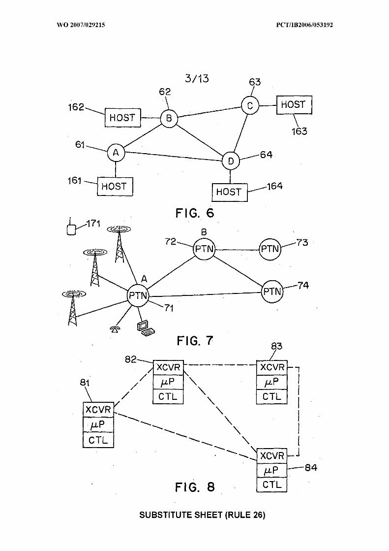
161.- HOST 1 HOST
FIG. 6
82
CTL CTL
\ I \ \
I CTL 1
FIG. 8
SUBSTITUTE SHEET (RULE 26)

FIG. 9
PROCESSING DATA PROCESSING
FIG. 10
SUBSTITUTE SHEET (RULE 26)

FIG. 11
/ \ IUL
OCP OCP 1 \ / \ OCP
/ OCP
103 64 105 \ 98
FIG. 12
SUBSTITUTE SHEET (RULE 26)

FIG. 14
SUBSTITUTE SHEET (RULE 26)

SUBSTITUTE SHEET (RULE 26)

FIG. 16
FIG. 17
SUBSTITUTE SHEET (RULE 26)

Window B R
Control ler 182. Signalling
\ Decoder,
Home PoweiliK6 Bus
Multidrop LAN
SUBSTITUTE SHEET (RULE 26)
194 193
LAN Interf ,ace
Microprocessor
/
LAN Inter? ace
Microprocessor
\
L A N Inter face
Microprocessor

FIG. 20
SUBSTITUTE SHEET (RULE 26)

SUBSTITUTE SHEET (RULE 26)
Multidrop LAN
2 0 4
Scaleable Scaleable Master Br i dge 2 0 2
Control ler Control ler Control Point
Multidrop LAN
2 0 2
Scaleable Scaleable Scaleable b
Controller Control ler Controller Bridge Router
IU Sca lea b le
Controller % Hub
Scaleable Controller
FIG. 21 Scalea ble Control ler
Scaleable Controller

M C P
FCP
\ /cp 2cp\ SCP
OCP OCP OCP \
OCP
$5 Interface
21 0 -/ ' I ECS
FIG. 23
SUBSTITUTE SHEET (RULE 26)

FIG. 25
SUBSTITUTE SHEET (RULE 26)
SPD -
Film or Power Generation Glass
and Conversion 1 Waveform Generation
Command Communications Execution and
Control
CAN Bus, LIN Bus or Zig Bee A/D Array
FIG. 24