international brick/block masonry c o n f e r e n · pdf fileto out of plane loading and to...
TRANSCRIPT
12TH INTERNATIONAL
BRICK/BLOCK Masonry c O N F E R E N C E
SOFTWARE FOR THE DESIGN OF CONCRETE MASONRY WAllS, SHEAR WAllS AND lINTElS
Russell H. Brown\ james K. Nelson, jr. 2, jeffrey H. Greenwald 3
and Robert S. Zobel 4
'Professor of Civil Engineering, Clemson University, Clemson, SC 29634-0911 , USA
' Professor and Chairman of Civil Engineering, Clemson University, Clemson, SC 29634-0911, USA
'Director of Codes and Standards, National Concrete Masonry Association,
2302 Horse Pen Rd ., Herndon, VA 20171-3499, USA
' Manager of Research and Development, National Concrete Masonry Association,
2302 Horse Pen Rd ., Herndon, VA 20171-3499, USA
ABSTRACT
The first development phase for software to design concrete masonry walls subjected to out of plane loading and to design concrete masonry and reinforced concrete lintels has been completed. This paper describes the second phase of the software development that includes shear walls, strength design and using the provisions of the 2000 International Building Code. Shear wall design can be performed using either strength design or allowable stress design procedures, and can be reinforced or unreinforced. Reinforcing steel options include distributed reinforcing that occurs at regular intervals along the wall and additional concentrated reinforcing steel that the user may add to each end of the wall. The algorithms use the steel area in each cell to formulate the interaction diagram and to determine if the user-specified design is adequa te for the defined loads. A plot of the interaction diagram with the criticaI design forces superimposed will be available to assist the user in assessing the efficiency of the designo The strength design capability will include slender wall provisions. For out-of-plane loadings, the reinforcing steel may be located off-center for retaining walls or basement walls. The user may specify the criticaI design forces or may choose to have them calculated based on specified design loads and dimensions. In the latter case, factored load combinations are calculated at very small intervals along the wall, and the criticai design forces are determined and reported. Since the criticai sec-
333
334
tion forces for flexure and for shear may occur at different locations on the wall, the forces and location of each are reported separately. Finally the user is provided with printed documentation in a form suitable for inclusion in design calculations. The software was developed using Microsoft Visual C++ with the Microsoft Foundation Classes. It is designed to operate on Windows 9x and NT 4.0 platforms. Extensive on-line help is included to assist the user in 011 aspects of the software application.
Key words: Masonry, concrete masonry, software, structural design, shear walls, lintels, sstrenght, shear walls, lintels, strength desing, allowable stress design, Intrnational Buildin Code.
INTRODUCTION
The authors have previously reported on the development of Phase I of the software (Ref.1). Phase I was released in fali of 1999. Before being released it was beta tested by Clemson University graduate student (Burgess) using independently developed computer algorithms and MathCad software. The second phase of the software will expand the capabilities of the first phase to include design of shear walls by both allowable stress design and strength design and design of out-of-plane walls by strength designo The lintel portion of Phase I will also be updated to the International Building Code (lCC 2000) as will ali portions of Phase 11. The software is limited to concrete masonry, single wythe construction. Walls can be solidly grouted or partially grouted (including ungrouted), and reinforcing may be included within grouted cells. The reinforcing steel may be in the center of the wall or off center, as might be the case for basement wall construction . Other modifications to Phase I include a new loading tab that combines ali loading entries into one tab, a code menu that allows the user to select from several design codes and a single data entry option for material properties in the lintel, out-of-plane and in-plane wall design portions. Finally, the lateral loading from soil, which was previously limited to full wall height can now occur over only part of the wall height as would be the case for a foundation wall w ith backfill that does not come to the elevation of the top of the wall.
REVISIONS TO USER INTERFACE
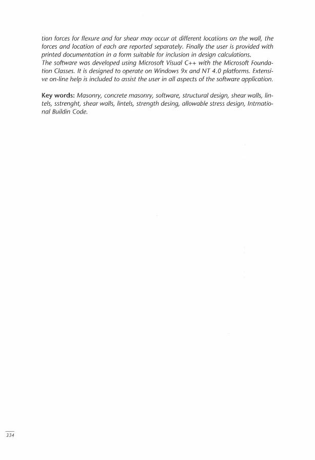
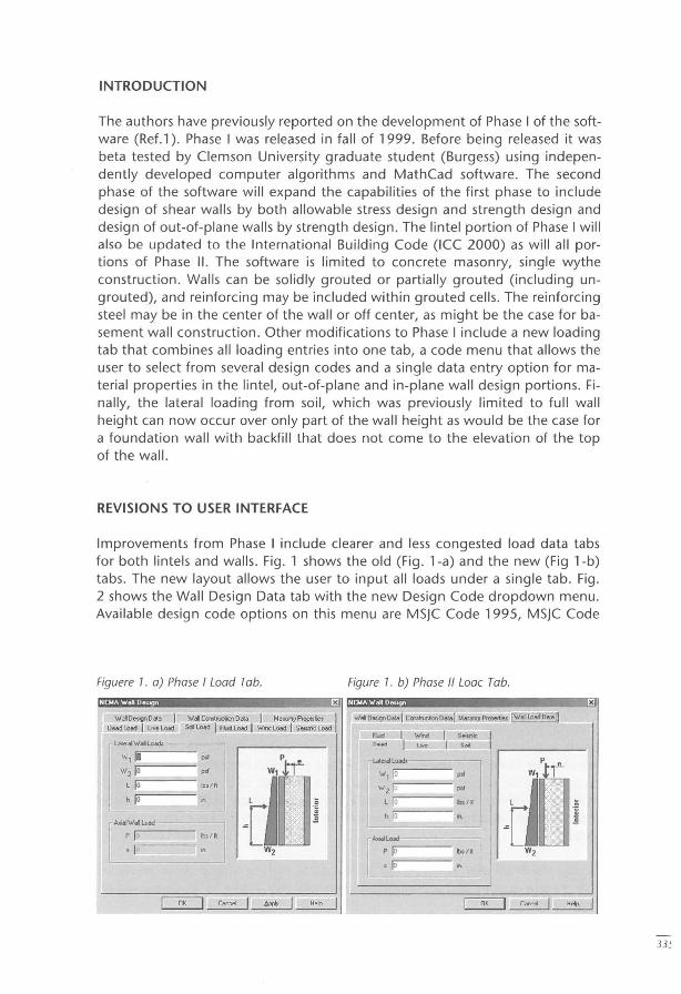
Improvements from Phase I include clearer and less congested load data tabs for both lintels and walls . Fig . 1 shows the old (Fig. l-a) and the new (Fig 1-b) tabs . The new layout allows the user to input ali loads under a single tab. Fig . 2 shows the Wall Design Data tab with the new Design Code dropdown menu . Available design code options on this menu are MSjC Code 1995, MSjC Code
Figuere 1. a) Phase I Load Tab. Figure 1. b) Phase " Loae Tab.
mG~am~ .................... ~x~ x
"'alO.,;gnO... I u""' ..... I uvo .....
"'ai Conolrudicn o... I M •• aoy Prope.Iie> I SoiLoad I "bel ~ I WlI"ICload 1 SetS(l1cLoad
" , 18 pof
"'2 '"lo --- p.f
l lo Ib3/ft
h lo
WalO""",O".,I c<rntrucbono ... l M""""._. ~~
Füd I W'm 5"""", O..dILiYo ,~
"',/0 Wz l""U- -=-'"
l lo 1>0 "
h jo
33~
336
Figure 2. Wall Design Data with Design (ode Tab.
. ..... . XI
v/ali Design Dalal C",slruelion Dala I Masonry Pro, .rlies 1 Wall l.o.d Da·a I =
Forces at D ~$ign Section
r~""-"" " lo lu/fi r- RClntorccd Mo~onry VI::!D
ML lo Ib·rn / II r Unreinforeed M .. onryVJaU
-
Ilr
F lo Ib I ft I Sirrply supporled Vlall ::J -e lu rn !'
r Comp.ltii' U ~lng Load Data ce.i~n Code I Dropdown menu for bui ld ing
co de se lecti on. Choices are íli!i'@diM$MiI4iA i P - MSJC 1999, MSJC 1995 r Use 1/3 Stre:s lncreas. and IBC 2000
Drsçlay De.gn Resulto Req'dA s Jo ,q.ln,
Use J"4 Bars (A=L20. D=O.500) 3 rm.re-
[ O;'" I O .. ;~ "''''';m, 3" I f .. "r,. 1 il il Grade I Grade 60 Ify = 60ksi) .:.I
I nK I r J'tr r.F'1
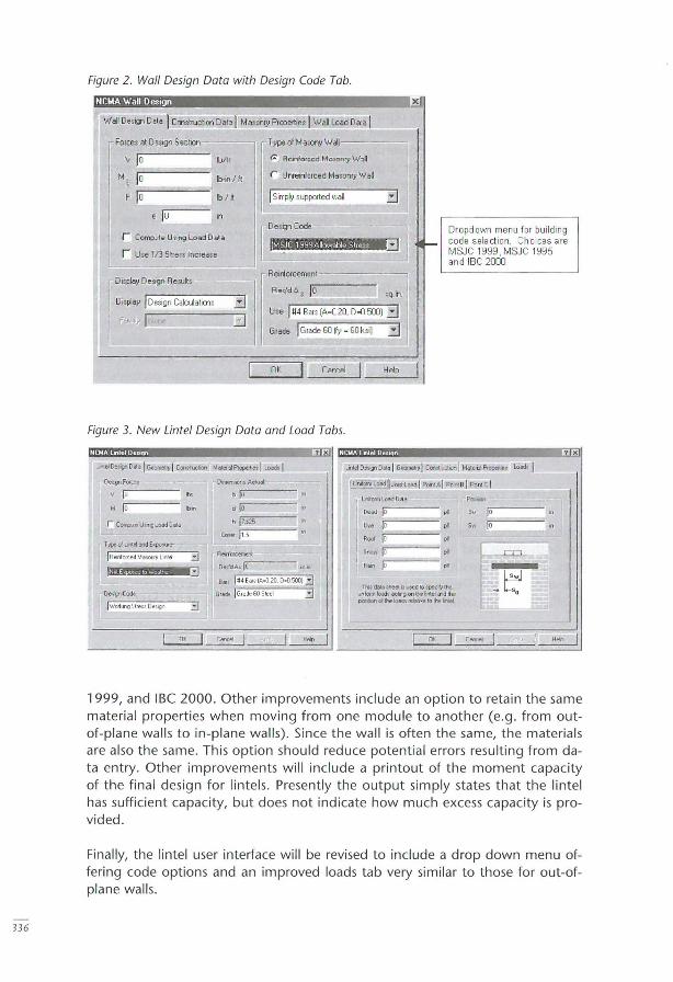
Figure 3. New Untei Design Data and Load Tabs.
De~FOIc,:
v lu M I "'0- - - - ...,
r C~e UwlÇ load (l at&
I H" ln J
[Ui.l2;;;;I"'iIlI J~. L.,dl PoriAI P,.' 9 I p",", cl
~L~:~m :r::-oad_D_4_' __ ~ Rod lo " s""" Jõr;;----==-- " R~ ~ '"
l his d6l..t :heel:kmed lDspecWlhe unfOlm ~di actr g on the "'el em the ~ol'hell.>lm feUlf.e,o thellntel
'0 1"'0----·
Sw lo
x
1999, and IBC 2000. Other improvements include an option to retain the same material properties when moving from one module to another (e.g. from outof-plane walls to in-plane walls). Since the wall is often the same, the materiais are also the same. This option should reduce potential errors resulting from data entry. Other improvements will include a printout of the moment capacity of the final design for lintels. Presently t he output simply states that the lintel has sufficient capacity, but does not indicate how much excess capacity is provided.
Finally, the lintel user interface will be revised to include a drop down menu offering code options and an improved loads tab very similar to those for out-ofplane walls.
STRENGTH DESIGN OF WALLS LOADED OUT-OF-PLANE
Strength design provisions for out-of-plane walls are based on IBC 2000. These provisions require an upper limit on the amount of reinforcing steel permitted in the wall and include a rigorous calculation of P-L\ effects ofaxial loads. Ali of these provisions are included in the calculations of the wall capacity. The upper limit of reinforcing steel is based on achieving a strain in the reinforcing steel of 1.3 times Ey when the masonry compressive strain is at 0.0025. The same capabilities will apply to strength design as were applied to allowable stress design of out-ofplane walls in Phase I of the software development. Reinforcing ranging in size from #3 to #9 bars may be placed at any recurring spacing up to 120 inches. Bars may be placed off center to accommodate the efficient design of foundation and retaining walls. Boundary conditions of walls may be pinned-pinned, fixed-free or fixed-pinned.
DESIGN OF SHEAR WALLS
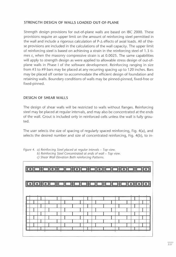
The design of shear walls will be restricted to walls without flanges. Reinforcing steel may be placed at regular intervals, and may also be concentrated at the ends of the wall. Grout is included only in reinforced cells unless the wall is fully grouted .
The user selects the size of spacing of regularly spaced reinforcing, Fig. 4(a), and selects the desired number and size of concentrated reinforcing, Fig . 4(b), to in-
Figure 4. a) Reinforcing 5teel placed at regular intevals - Top view. b) Reinforcing 5teel Concentrated at ends of wall - Top view. c) 5hear Wall Elevation 80th reinforcing Pattems.
IJ:!ILJICJ~lr 1l.:iII:!lI:-:iI~r.lILJCJlr.1CJll..:IWI
I[!JWI~DID~ 111 n lU lDIDDID[!]IW~1
I I I I I I I I I I I I I I I
I I I I I I I I I I I I I I I
I I I I I I I I 1 I I I I I I
I I I I I I I I I I I I I I I
337
338
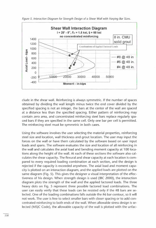
Figure 5. Interaction Diagram for Strength Design of a Shear Wall with Varying Bar Sizes.
Shear Wall Interaction Diagram I = 20' - 8", fm = 1.5 ksi, ~ = 60 ksi
1400
1200
li) 1000 ,
c.. 800 t :;;;: r #8@48 i:-'ti 600
C'CI - #6@48 in. o 400 ...J
C'CI #4 @48 in . ';( 200 I
« o I -200 40QOO 50 00
-400 Moment - in-kips
clude in the shear wall. Reinforcing is always symmetric. If the number of spaces obtained by dividing the wall length minus twice the end cover divided by the specified spacing is not an integer, the bars at the center of the wall are spaced at a distance less than the specified spacing. Either pattern of reinforcing may contain zero area, and concentrated reinforcing steel bars replace regularly spaced bars if they are specified in the same cell. Only one bar per cell is permitted. The reinforcing steel must be symmetric in both cases.
Using the software involves the user selecting the material properties, reinforcing steel size and location, wall thickness and grout location. The user may input the forces on the wall or have them calculated by the software based on user input loads and spans. The software evaluates the size and location of ali reinforcing in the wall and calculates the axial load and bending moment capacity at 100 locations along the height of the wall. At each of these sections the software also calculates the shear capacity. The flexural and shear capacity at each location is compared to every required loading combination at each section, and the design is rejected if the capacity is exceeded anywhere. The axial load and moment capacity is plotted on an interaction diagram, and the applied loads are plotted on the same diagram (Fig. 5). This gives the designer a visual interpretation of the effectiveness of his designo When strength design is used (IBC 2000), the interaction diagram plots the strength of the wall and the applied factored loads. The three heavy dots on Fig. 5 represent three possible factored load combinations. The user can easily verify that these loads can be resisted only if the #8 bars are selected. One of the loading combinations falls outside the #6 bar contour, so it will not work. The user is free to select smaller bars with closer spacing or to add concentrated reinforcing to both ends of the wall. When allowable stress design is selected (MS]C Code), the allowable capacity of the wall is plotted with the unfac-
tored loads superimposed. In cases where the code permits a one-third increase in allowable stresses due to combined wind or earthquake, the loading combinations that include the 1/3 increase are multiplied by three-fourths and plotted on the same diagram as those without the increase. In this way, only one interaction diagram is needed rather than including a second one with 1/3 allowable stress increase.
The upper limit of reinforcing steel for strength design is based on achieving a strain in the reinforcing steel of 5 times Ey when the masonry compressive strain is at 0.0025. Unfactored gravity axialloads are included, and the stress in the tension steel is taken as 1.25 fy. A Whitney stress block is used having a stress of 0.80 f'm and a depth of 80% of the depth of the neutral axis. IBC 2000 also has special provisions to ensure that walls fail in flexure instead of shear. The shear capacity is also required to be at least 1.25 times the flexural capacity.
REFERENCES
Brown, R.H., Nelson, j.K., jr. and Greenwald, j.H., Software for the Design of Concrete Masonry Wal/s and Unte/s, Proceedíngs, 8 th North Amerícan Masonry Conference, june 1999, Austin, TX, R. E. Klingner, Editor.
Burgess, Robert E., Verification of Masonry Design Software Developed for the National Concrete Masonry Association, A Special Project in Partia I Fulfillment of the Requirements for the Master of Engineering Degree, Clemson University, Clemson, SC, Dec. 16, 1999, 143 pages.
MSjC 1995 or 1999, Masonry Standards joint Committee, Bui/ding Code Requirements for Masonry Structures (ACl530/ ASEC5/ TMS402), using either the 1995 or 1999 version.
IBC 2000, International Building Code, International Code Council, 5203 Leesburg Pike, Suite 708, Falls Church VA 22041, USA.
339
