internal repair of pipelines semi-annual technical .../67531/metadc786772/m2/1/high... · internal...
TRANSCRIPT
EWI Project No. 46211GTH Electronic File Name: 41633R15.pdf
Internal Repair of Pipelines Semi-Annual Technical Progress Report
Reporting Period: September 30, 2002 through March 31, 2003
Principal Authors: Robin Gordon, Bill Bruce, Nancy Porter, Mike Sullivan, and Chris Neary
Report Issued: May 2003 Revised: June 24, 2003
Revision #1
DOE Award No.: DE-FC26-02NT41633
Submitted By: Edison Welding Institute
1250 Arthur E. Adams Drive Columbus, OH 43221
Significant Subcontractor:
Pacific Gas & Electric 3400 Crow Canyon Road San Ramon, CA 94583
ii 41633R15.pdf
DISCLAIMER This report was prepared as an account of work sponsored by an agency of the United States Government. Neither the United States Government nor any agency thereof, nor any of their employees, makes any warranty, express or implied, or assumes any legal liability or responsibility for the accuracy, completeness, or usefulness of any information, apparatus, product, or process disclosed or represents that its use would not infringe privately owned rights. Reference herein to otherwise does not necessarily constitute or imply its endorsement, recommendation, or favoring by the United States Government or any agency thereof. The views and opinions of authors expressed herein do not necessarily state or reflect those of the United States Government or any agency hereof. Measurement Units -- SI Metric System of Units are the primary units of measure for this report followed by their U.S. Customary Equivalents in parentheses ( ). Note: SI is an abbreviation for "Le Systeme International d'Unites."
iii 41633R15.pdf
ABSTRACT The two broad categories of deposited weld metal repair and fiber-reinforced composite repair technologies were reviewed for potential application for internal repair of gas transmission pipelines. Both are used to some extent for other applications and could be further developed for internal, local, structural repair of gas transmission pipelines. Preliminary test programs were developed for both deposited weld metal repairs and for fiber-reinforced composite repair. To date, all of the experimental work pertaining to the evaluation of potential repair methods has focused on fiber-reinforced composite repairs. Hydrostatic testing was also conducted on four pipeline sections with simulated corrosion damage: two with composite liners and two without.
iv 41633R15.pdf
TABLE OF CONTENTS
Page DISCLAIMER ...................................................................................................................ii ABSTRACT ..................................................................................................................... iii TABLE OF CONTENTS ..................................................................................................iv
LIST OF GRAPHICAL MATERIALS................................................................................ v
1.0 - INTRODUCTION..................................................................................................... 1
2.0 - EXECUTIVE SUMMARY ........................................................................................ 5
3.0 - EXPERIMENTAL .................................................................................................... 6
4.0 - RESULTS AND DISCUSSION.............................................................................. 12 Task 1.0 - Research Management Plan ..............................................................................12 Task 2.0 - Technology Status Assessment .........................................................................12 Task 3.0 - Review Operators Experience and Repair Needs ..............................................12 Task 4.0 - Evaluate Potential Repair Methods ....................................................................17
5.0 - CONCLUSIONS.................................................................................................... 24
6.0 - REFERENCES...................................................................................................... 26
7.0 - BIBLIOGRAPHY ................................................................................................... 27
8.0 - LIST OF ACRONYMS........................................................................................... 29
9.0 - APPENDICES....................................................................................................... 30 Appendix A - Draft Industry Survey................................................................................... A-1
Appendix B - Members of the Pipeline Research Council International............................ B-1
Appendix C - List of Natural Gas Pipeline Operating Companies..................................... C-1
Tables Page
Table 1 .......................................................................................................................... 23
v 41633R15.pdf
LIST OF GRAPHICAL MATERIALS Page
Figure 1 - Installation of a Full-Encirclement Repair Sleeve ......................................................... 1 Figure 2 - External Weld Deposition Repair of Internal Wall Loss in 90 Degree Elbow................ 2 Figure 3 - Osaka Gas System for Remote Robotic Internal Repair of Root Weld Defects in Gas
Transmission Pipelines.......................................................................................................... 2 Figure 4 - Clock Spring® Fiber-Reinforced Composite Device for Pipeline Repair ...................... 3 Figure 5 - Installation of a Sectional Liner in Low-Pressure Pipeline............................................ 4 Figure 6- RolaTube Bi-Stable Reeled Composite Material ........................................................... 6 Figure 7 - Lay-Up and Forming of Fiber-Reinforced Composite Liner.......................................... 7 Figure 8 - Insertion of Liner into 114.3 mm (4.5 in.) Diameter Pipe .............................................. 8 Figure 9 - Silicon Rubber Bag Inserted into Liner ......................................................................... 8 Figure 10 - Oven Used to Heat Pipe and Liner to 200°C (392°F)................................................. 9 Figure 11 - Liner Inserted into Center of 114.3 mm (4.5 in.) Diameter Pipe ................................. 9 Figure 12 - Long, Shallow Simulated Corrosion Damage........................................................... 10 Figure 13 - Short, Deep Simulated Corrosion Damage .............................................................. 10 Figure 14 - 114.3 mm (4.5 in.) Diameter Pipe with End Caps Welded and Simulated Corrosion
Damage Introduced ............................................................................................................. 11 Figure 15 - Experimental Set-Up for Welding onto Thin-Wall Pipe containing Pressurized
Methane Gas ....................................................................................................................... 14 Figure 16 - External Appearance of Welds Made on 3.2 mm (0.125 in.) Thick Pipe with Methane
Gas at 4.5 mPa (650 psi) and 6.1 m/sec (19.9 ft/sec) Flow Rate ........................................ 15 Figure 17 - Internal Appearance of Welds Shown in Figure 16 .................................................. 15 Figure 18 - Metallographic Section through Weld 2M9 (middle weld shown in Figure 16 and
Figure 17) ............................................................................................................................ 16 Figure 19 - Eutectic Iron Layer at Inside Surface of Metallographic Section through Weld 2M9 16 Figure 20 - Cracks in Eutectic Iron Layer of Metallographic Section Shown in Figure 19 .......... 17 Figure 21 - Hydrostatic Test Rupture of Long, Shallow Simulated Corrosion Damage in Pipe
Section Containing Fiber-Reinforced Composite Liner........................................................ 19 Figure 22 - Hydrostatic Test Leak of Short, Deep Simulated Corrosion Damage in Pipe Section
Containing Fiber-Reinforced Composite Liner..................................................................... 20 Figure 23 - Section Taken Hydrostatic Test Rupture of Long, Shallow Simulated Corrosion
Damage in Pipe Section Containing Fiber-Reinforced Composite Liner ............................. 21 Figure 24 - Fiber-Reinforced Composite Liner in Ruptured Pipe Section Containing Long,
Shallow Simulated Corrosion Damage Fiber-Reinforced Composite Repairs..................... 21
1 41633R15.pdf
1.0 - INTRODUCTION
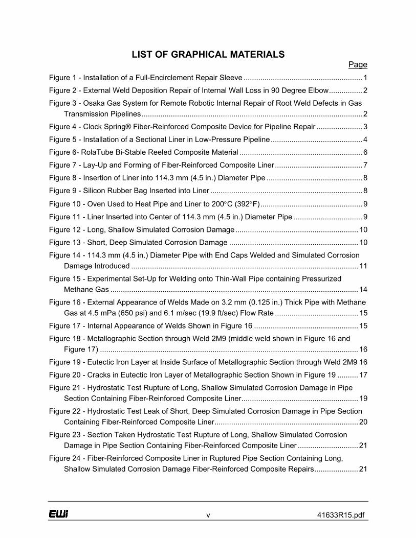
Repair methods that can be applied from the inside of a gas transmission pipeline (i.e., trenchless methods) are an attractive alternative to conventional repair methods since the need to excavate the pipeline is precluded. This is particularly true for pipelines in environmentally sensitive and highly populated areas. Several repair methods that are commonly applied from the outside of the pipeline are, in theory, directly applicable from the inside. However, issues must be addressed such as development of the required equipment to perform repairs remotely and the mobilization of said equipment through the pipeline to areas that need to be repaired. Also, several additional repair methods that are commonly applied to other types of pipelines (gas distribution lines, water lines, etc.) have potential applicability but require further development to meet the requirements for repair of gas transmission pipelines. Gas transmission pipeline repair by direct deposition of weld metal, or weld deposition repair, is a proven technology that can be applied directly to the area of wall loss (e.g., external repair of external wall loss - Figure 1) or to the side opposite the wall loss (e.g., external repair of internal wall loss – Figure 2).
Figure 1 - Installation of a Full-Encirclement Repair Sleeve
2 41633R15.pdf
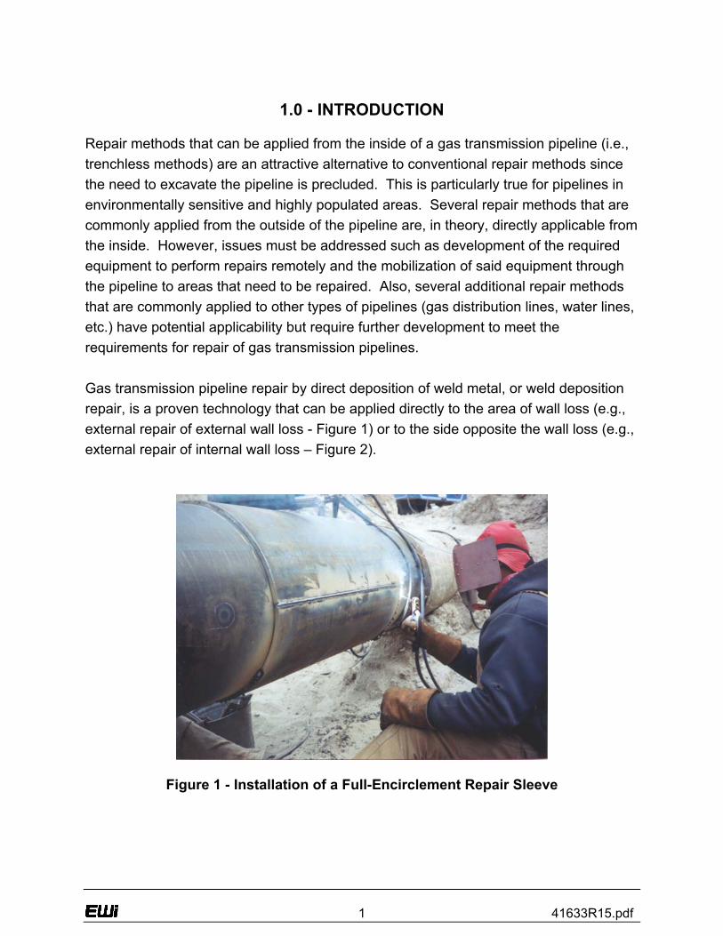
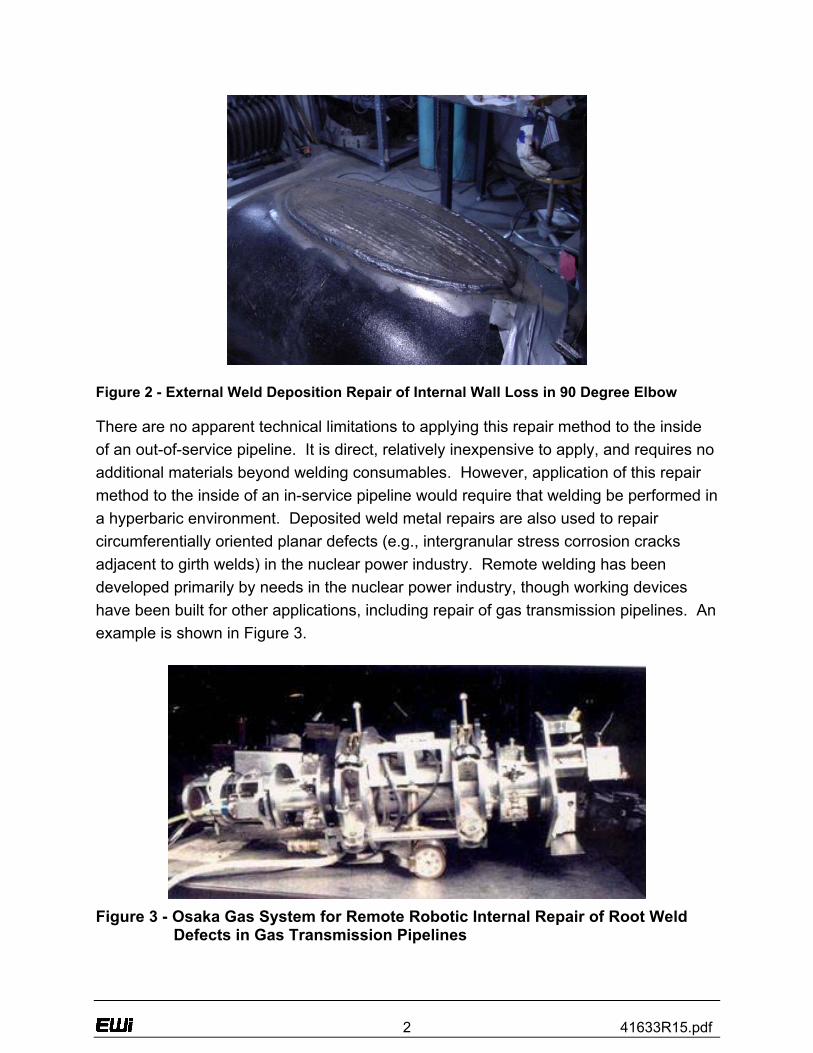
Figure 2 - External Weld Deposition Repair of Internal Wall Loss in 90 Degree Elbow There are no apparent technical limitations to applying this repair method to the inside of an out-of-service pipeline. It is direct, relatively inexpensive to apply, and requires no additional materials beyond welding consumables. However, application of this repair method to the inside of an in-service pipeline would require that welding be performed in a hyperbaric environment. Deposited weld metal repairs are also used to repair circumferentially oriented planar defects (e.g., intergranular stress corrosion cracks adjacent to girth welds) in the nuclear power industry. Remote welding has been developed primarily by needs in the nuclear power industry, though working devices have been built for other applications, including repair of gas transmission pipelines. An example is shown in Figure 3.
Figure 3 - Osaka Gas System for Remote Robotic Internal Repair of Root Weld
Defects in Gas Transmission Pipelines
3 41633R15.pdf
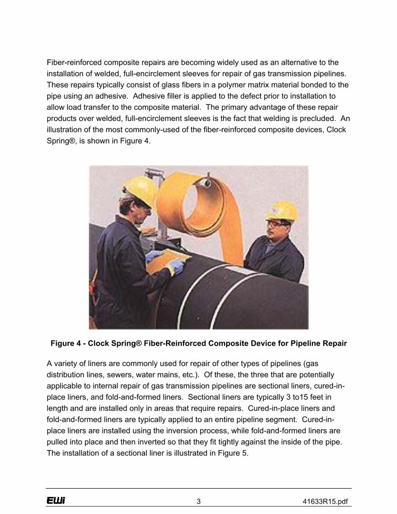
Fiber-reinforced composite repairs are becoming widely used as an alternative to the installation of welded, full-encirclement sleeves for repair of gas transmission pipelines. These repairs typically consist of glass fibers in a polymer matrix material bonded to the pipe using an adhesive. Adhesive filler is applied to the defect prior to installation to allow load transfer to the composite material. The primary advantage of these repair products over welded, full-encirclement sleeves is the fact that welding is precluded. An illustration of the most commonly-used of the fiber-reinforced composite devices, Clock Spring®, is shown in Figure 4.
Figure 4 - Clock Spring® Fiber-Reinforced Composite Device for Pipeline Repair
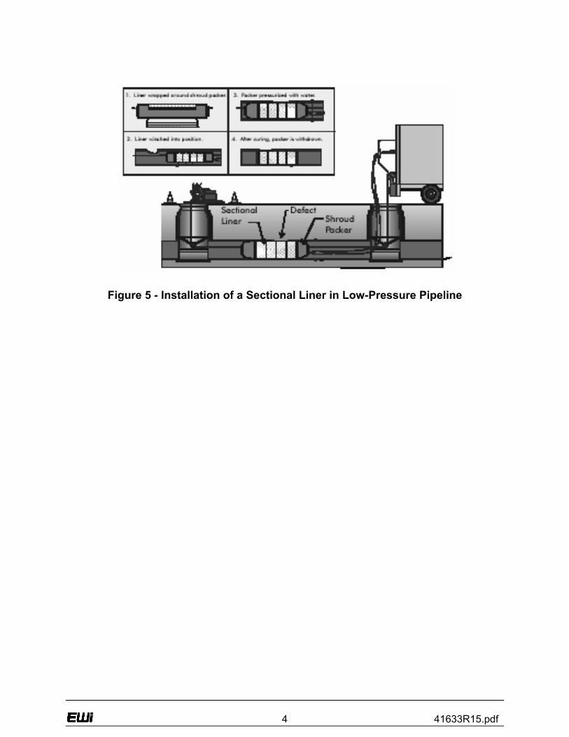
A variety of liners are commonly used for repair of other types of pipelines (gas distribution lines, sewers, water mains, etc.). Of these, the three that are potentially applicable to internal repair of gas transmission pipelines are sectional liners, cured-in-place liners, and fold-and-formed liners. Sectional liners are typically 3 to15 feet in length and are installed only in areas that require repairs. Cured-in-place liners and fold-and-formed liners are typically applied to an entire pipeline segment. Cured-in-place liners are installed using the inversion process, while fold-and-formed liners are pulled into place and then inverted so that they fit tightly against the inside of the pipe. The installation of a sectional liner is illustrated in Figure 5.
4 41633R15.pdf
Figure 5 - Installation of a Sectional Liner in Low-Pressure Pipeline
5 41633R15.pdf
2.0 - EXECUTIVE SUMMARY
The two broad categories of deposited weld metal repair and fiber-reinforced composite repair technologies were reviewed for potential application for internal repair of gas transmission pipelines. Both are used to some extent for other applications and could be further developed for internal, local, structural repair of gas transmission pipelines. Although both of these repair technologies can easily be applied out-of-service, both require excavation prior to repair. The most frequent cause for repair of gas transmission pipelines was identified as external, corrosion-caused loss of wall thickness. The most commonly used in-service method for repair is welding on a full-encirclement steel sleeve. Weld deposition repair is a proven technology that can be applied directly to the area of wall loss. There are no apparent limitations to applying this repair technology to the outside of an out-of-service pipeline. Application of this repair to the inside of an in-service pipeline would require that welding be performed in a hyperbaric environment. Fiber-reinforced composite repairs are becoming widely used as an alternative to welding. Three liners that are potentially applicable to internal repair of pipelines are sectional liners, cured-in-place liners, and fold-and-formed liners. External corrosion can also be repaired by applying adhesive to the defect and wrapping a fiber-reinforced composite material around the outside diameter of the pipeline. Preliminary test programs were developed for both deposited weld metal repairs and for fiber-reinforced composite repair. Areas of damage were artificially introduced into pipe sections using methods previously developed at EWI. RoloTube developed a modified version of their fiber-reinforced composite with nine plies of glass-polypropylene in the form of overlapping pre-pregnated tapes of unidirectional glass and polymer. These liners were inserted into two damaged pipe sections and two damaged pipe sections had no lining. All four damaged pipe sections were hydrostatically tested until rupture. The two pipes with liners failed at pressures only marginally greater than the pipe with no liner. It was determined that the liner material was not as elastic as the steel pipe and therefore not able to carry its share of the load. RoloTube is currently redesigning the liner with a carbon/polypropylene material that should carry a greater load. During the next reporting period, preliminary test programs for deposited weld metal repairs will be initiated and fiber-reinforced composite repairs will continue into the next phase of the project.
6 41633R15.pdf
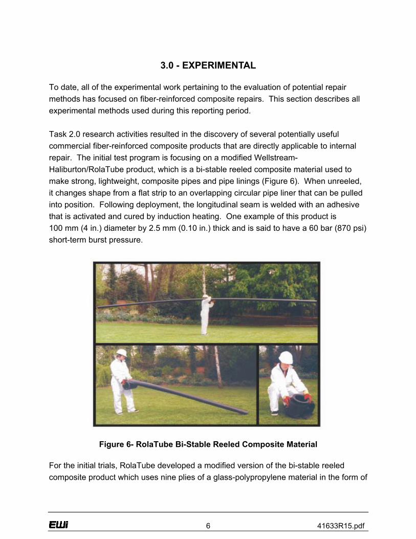
3.0 - EXPERIMENTAL To date, all of the experimental work pertaining to the evaluation of potential repair methods has focused on fiber-reinforced composite repairs. This section describes all experimental methods used during this reporting period. Task 2.0 research activities resulted in the discovery of several potentially useful commercial fiber-reinforced composite products that are directly applicable to internal repair. The initial test program is focusing on a modified Wellstream-Haliburton/RolaTube product, which is a bi-stable reeled composite material used to make strong, lightweight, composite pipes and pipe linings (Figure 6). When unreeled, it changes shape from a flat strip to an overlapping circular pipe liner that can be pulled into position. Following deployment, the longitudinal seam is welded with an adhesive that is activated and cured by induction heating. One example of this product is 100 mm (4 in.) diameter by 2.5 mm (0.10 in.) thick and is said to have a 60 bar (870 psi) short-term burst pressure.
Figure 6- RolaTube Bi-Stable Reeled Composite Material For the initial trials, RolaTube developed a modified version of the bi-stable reeled composite product which uses nine plies of a glass-polypropylene material in the form of
7 41633R15.pdf
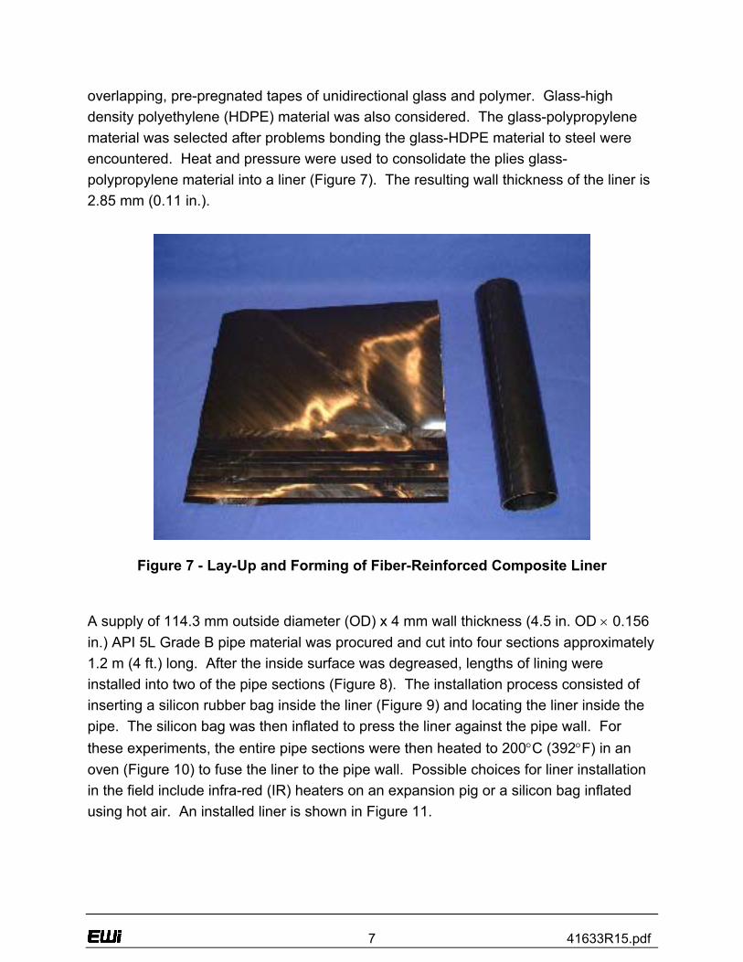
overlapping, pre-pregnated tapes of unidirectional glass and polymer. Glass-high density polyethylene (HDPE) material was also considered. The glass-polypropylene material was selected after problems bonding the glass-HDPE material to steel were encountered. Heat and pressure were used to consolidate the plies glass-polypropylene material into a liner (Figure 7). The resulting wall thickness of the liner is 2.85 mm (0.11 in.).
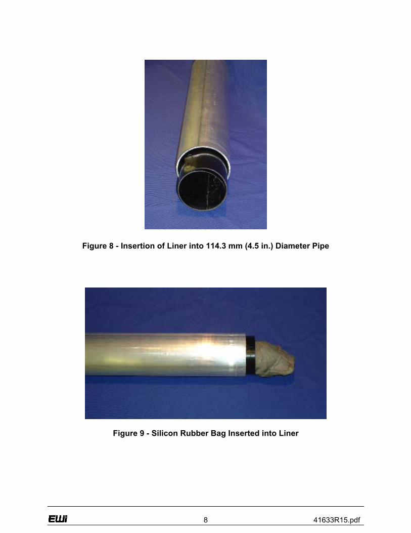
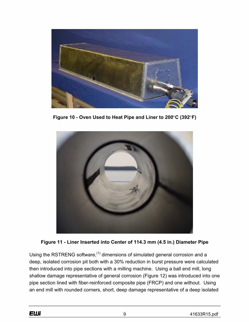
Figure 7 - Lay-Up and Forming of Fiber-Reinforced Composite Liner A supply of 114.3 mm outside diameter (OD) x 4 mm wall thickness (4.5 in. OD × 0.156 in.) API 5L Grade B pipe material was procured and cut into four sections approximately 1.2 m (4 ft.) long. After the inside surface was degreased, lengths of lining were installed into two of the pipe sections (Figure 8). The installation process consisted of inserting a silicon rubber bag inside the liner (Figure 9) and locating the liner inside the pipe. The silicon bag was then inflated to press the liner against the pipe wall. For these experiments, the entire pipe sections were then heated to 200°C (392°F) in an oven (Figure 10) to fuse the liner to the pipe wall. Possible choices for liner installation in the field include infra-red (IR) heaters on an expansion pig or a silicon bag inflated using hot air. An installed liner is shown in Figure 11.
8 41633R15.pdf
Figure 8 - Insertion of Liner into 114.3 mm (4.5 in.) Diameter Pipe
Figure 9 - Silicon Rubber Bag Inserted into Liner
9 41633R15.pdf
Figure 10 - Oven Used to Heat Pipe and Liner to 200°C (392°F)
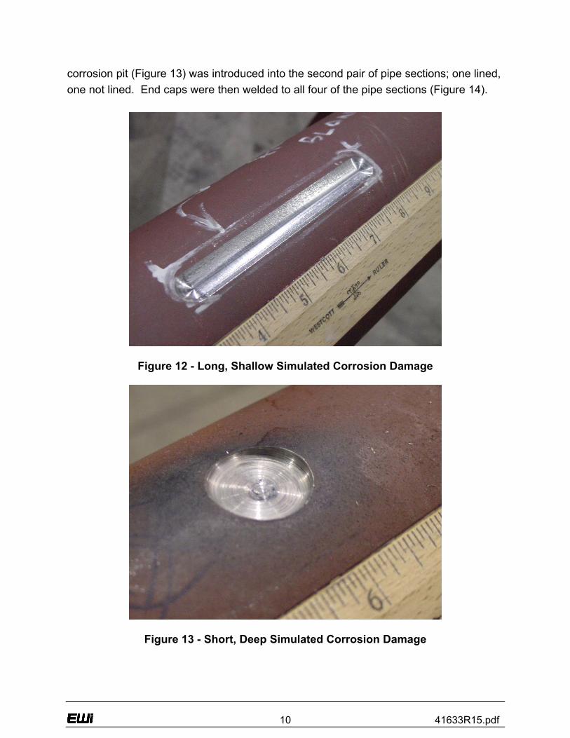
Figure 11 - Liner Inserted into Center of 114.3 mm (4.5 in.) Diameter Pipe Using the RSTRENG software,(1) dimensions of simulated general corrosion and a deep, isolated corrosion pit both with a 30% reduction in burst pressure were calculated then introduced into pipe sections with a milling machine. Using a ball end mill, long shallow damage representative of general corrosion (Figure 12) was introduced into one pipe section lined with fiber-reinforced composite pipe (FRCP) and one without. Using an end mill with rounded corners, short, deep damage representative of a deep isolated
10 41633R15.pdf
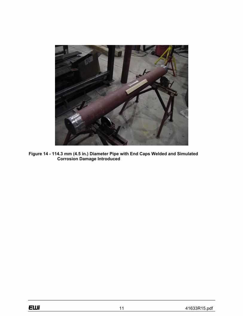
corrosion pit (Figure 13) was introduced into the second pair of pipe sections; one lined, one not lined. End caps were then welded to all four of the pipe sections (Figure 14).
Figure 12 - Long, Shallow Simulated Corrosion Damage
Figure 13 - Short, Deep Simulated Corrosion Damage
11 41633R15.pdf
Figure 14 - 114.3 mm (4.5 in.) Diameter Pipe with End Caps Welded and Simulated
Corrosion Damage Introduced
12 41633R15.pdf
4.0 - RESULTS AND DISCUSSION
This report describes progress pertaining to a project sponsored by the U.S. Department of Energy (DOE) National Energy Technology Laboratory (NETL) to develop internal repair technology for gas transmission pipelines. In order to thoroughly investigate repair technology, this project brings together a combination of partners that have a proven track record in developing pipeline repair technology. The project team consists of Edison Welding Institute (EWI), a full-service provider of materials joining engineering services; Pacific Gas & Electric (PG&E), a pipeline company that has a current need for the technology; and the Pipeline Research Council International (PRCI), an international consortium of pipeline companies, to provide project oversight and direction. EWI is the lead organization performing this Award for NETL located in Morgantown, West Virginia. Task 1.0 - Research Management Plan During this reporting period, the team created a Research Management Plan(2). This document contains a work breakdown structure and supporting narrative that concisely summarizes the overall project. The plan is an integration of the technical and programmatic data into one document that details the technical objectives and technical approach for each task and subtask. The document also contains detailed schedules and planned expenditures for each task and all major milestones/decision points. Task 2.0 - Technology Status Assessment During this reporting period, a report(3) was produced that presents the status of existing pipeline repair technology that can be applied to the inside of a gas transmission pipeline. This report describes the current state-of-the-art technologies that are being developed, including the positive and negative aspects of each technology. Task 3.0 - Review Operators Experience and Repair Needs This task consists of conducting a survey of pipeline companies to determine the situations where internal repair would be the preferred repair method for gas transmission pipelines. The intent of the survey is to determine the specific geographic locations and special situations where internal repairs would be most cost-effective.
13 41633R15.pdf
Subtask 3.1 - Define Repair Needs and Performance Requirements During this reporting period, a draft survey was developed (Appendix A). The survey is divided into the following parts:
• Currently-Used Repair Methods
• Use/Potential Use of Internal Repair
• Need for In-Service Internal Repair
• Applicable Types of Damage
• Operational and Performance requirements for Internal Repairs. During the next reporting period, the draft industry survey will be finalized and sent to pipeline operating companies. This survey will primarily focus on pipeline operating companies (gas transmission) that are members of the Pipeline Research Council International (Appendix B). The survey will also be sent to other pipeline operating companies (Appendix C). Following receipt of completed surveys, follow-up telephone calls will be made to further identify the range of pipeline sizes, materials and coating types in most common use and the types of pipeline damage and remediation/upgrades (to more stringent code requirements) that are most frequently encountered. The pipeline companies will also be asked to define specific operational and performance requirements for internal repairs, including post repair inspection and future pipeline inspection (i.e. pigging). The survey will also determine operating requirements such as the minimum and maximum distance a repair system needs to be able to travel inside a pipe to facilitate internal repair and potential obstructions such as elbows, bends, branches, and taps that may limit access. Companies that offer in-line inspection services will also be surveyed to determine the maximum geometric variations associated with internal repairs (particularly internal build-up, liner thickness, etc.) that can be tolerated by current and next generation in-line inspection vehicles (a.k.a. smart pigs). If the results of survey indicate that operators have a strong preference for the development of internal repair methods that can be applied while the pipeline remains in-service, a separate series of experiments will be carried out to investigate the effect of methane in the welding environment on the integrity of completed welds.
14 41633R15.pdf
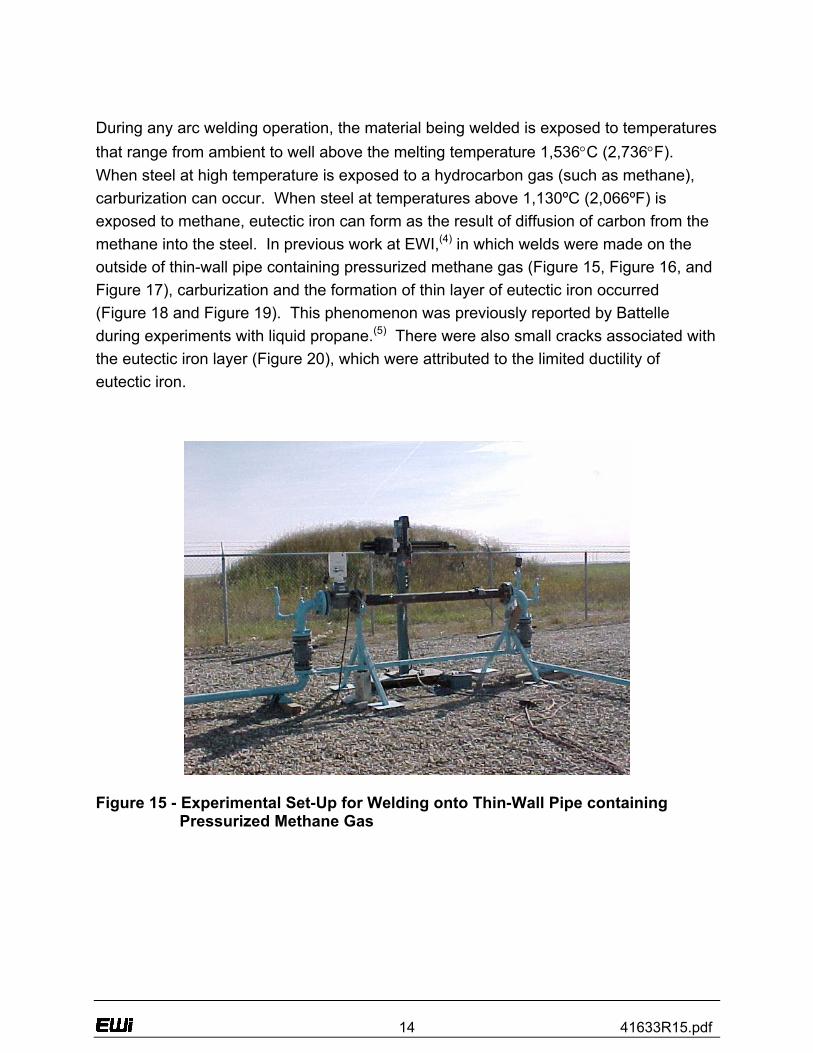
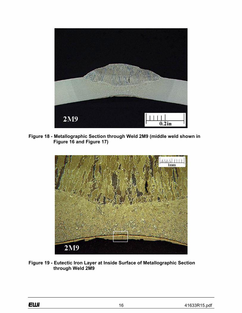
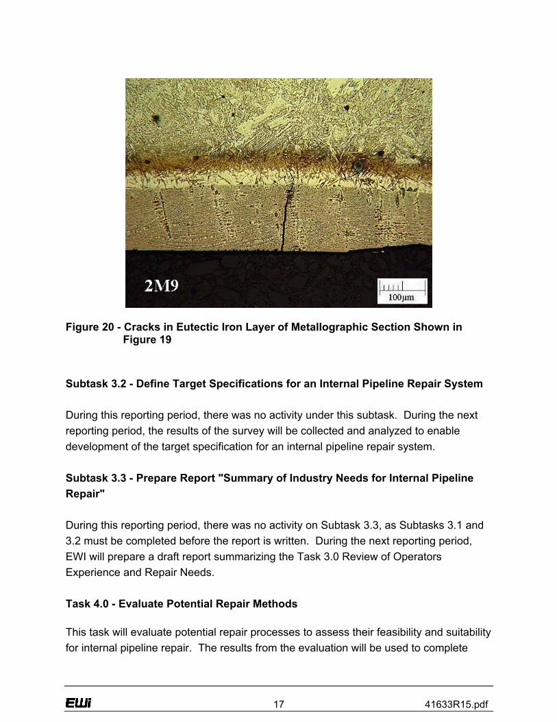
During any arc welding operation, the material being welded is exposed to temperatures that range from ambient to well above the melting temperature 1,536°C (2,736°F). When steel at high temperature is exposed to a hydrocarbon gas (such as methane), carburization can occur. When steel at temperatures above 1,130ºC (2,066ºF) is exposed to methane, eutectic iron can form as the result of diffusion of carbon from the methane into the steel. In previous work at EWI,(4) in which welds were made on the outside of thin-wall pipe containing pressurized methane gas (Figure 15, Figure 16, and Figure 17), carburization and the formation of thin layer of eutectic iron occurred (Figure 18 and Figure 19). This phenomenon was previously reported by Battelle during experiments with liquid propane.(5) There were also small cracks associated with the eutectic iron layer (Figure 20), which were attributed to the limited ductility of eutectic iron.
Figure 15 - Experimental Set-Up for Welding onto Thin-Wall Pipe containing
Pressurized Methane Gas
15 41633R15.pdf
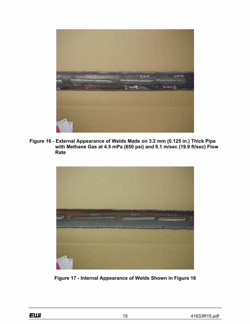
Figure 16 - External Appearance of Welds Made on 3.2 mm (0.125 in.) Thick Pipe
with Methane Gas at 4.5 mPa (650 psi) and 6.1 m/sec (19.9 ft/sec) Flow Rate
Figure 17 - Internal Appearance of Welds Shown in Figure 16
16 41633R15.pdf
Figure 18 - Metallographic Section through Weld 2M9 (middle weld shown in
Figure 16 and Figure 17)
Figure 19 - Eutectic Iron Layer at Inside Surface of Metallographic Section
through Weld 2M9
17 41633R15.pdf
Figure 20 - Cracks in Eutectic Iron Layer of Metallographic Section Shown in
Figure 19 Subtask 3.2 - Define Target Specifications for an Internal Pipeline Repair System During this reporting period, there was no activity under this subtask. During the next reporting period, the results of the survey will be collected and analyzed to enable development of the target specification for an internal pipeline repair system. Subtask 3.3 - Prepare Report "Summary of Industry Needs for Internal Pipeline Repair" During this reporting period, there was no activity on Subtask 3.3, as Subtasks 3.1 and 3.2 must be completed before the report is written. During the next reporting period, EWI will prepare a draft report summarizing the Task 3.0 Review of Operators Experience and Repair Needs. Task 4.0 - Evaluate Potential Repair Methods This task will evaluate potential repair processes to assess their feasibility and suitability for internal pipeline repair. The results from the evaluation will be used to complete
18 41633R15.pdf
Task 5.0. Consideration will be given to each method's applicability to planar or metal loss damage types and their suitability for in-service repair. Subtask 4.1 - Identify Potential Repair Methods During this reporting period, the Task 2.0 - Technology Status Assessment was used to identify two broad categories of repair technology that are potentially applicable to gas transmission pipelines from the inside. While it is anticipated that the results of the Task 3.0 survey will provide direction regarding which specific repair method should be emphasized in the experimental portion of the project, both deposited weld metal repairs and fiber-reinforced composite repairs are being investigated in the preliminary experiments in the Task 4.0 evaluation. During the next reporting period, the preliminary test programs for deposited weld metal repairs will be initiated and fiber-reinforced composite repairs will continue, as outlined below. Subtask 4.2 - Develop Internal Repair Test Program During this reporting period, all of the experimental work pertaining to the evaluation of potential repair methods has focused on fiber-reinforced composite repairs. Deposited Weld Metal Repairs During this reporting period, a preliminary test program for deposited weld metal repairs was developed. This test program will initially focus on the ability of internal weld deposition repair to restore the integrity of pipe sections containing external corrosion-caused wall loss. During the next reporting period, EWI will initiate this test program. A separate series of experiments to investigate the effect of methane in the welding environment on the integrity of completed weld will be planned and initiated, if the results of the Task 3.0 survey indicate that operators have a strong preference for the development of internal repair methods that can be applied while the pipeline remains in-service.
19 41633R15.pdf
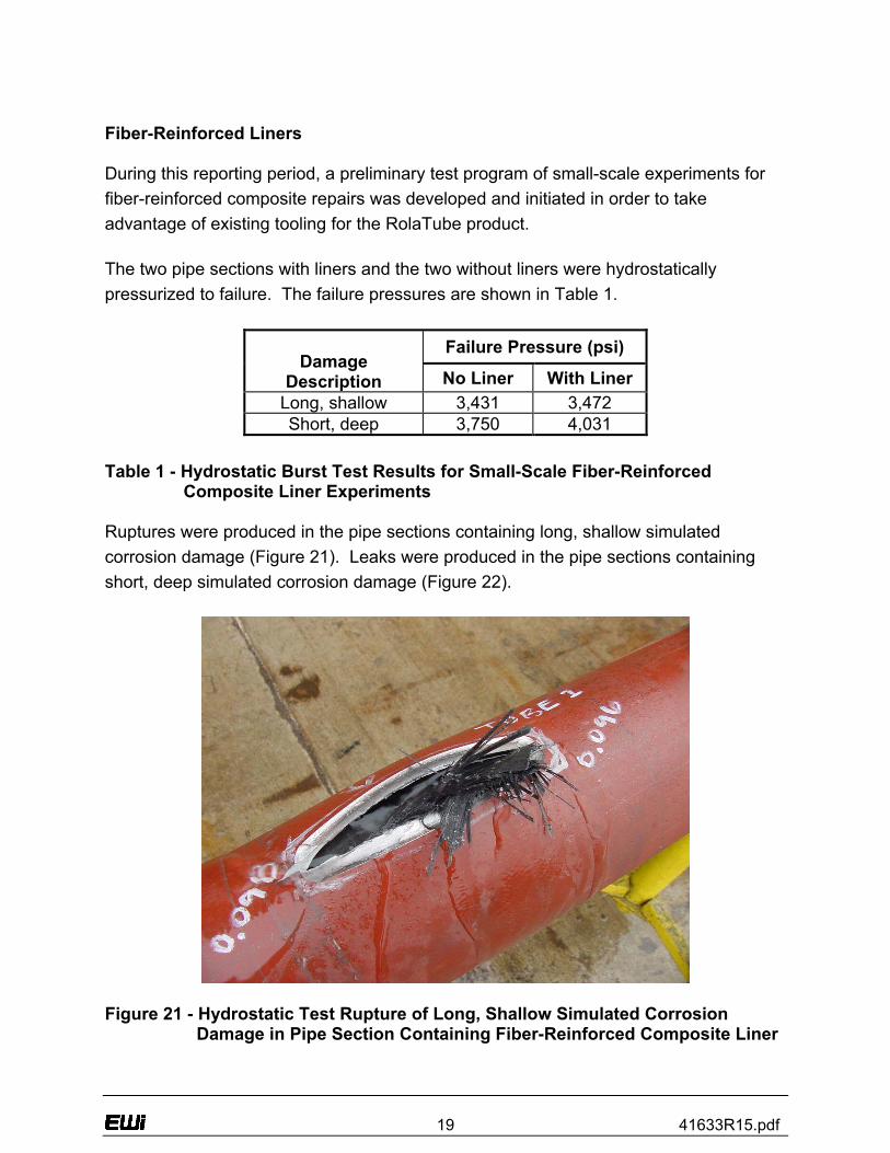
Fiber-Reinforced Liners During this reporting period, a preliminary test program of small-scale experiments for fiber-reinforced composite repairs was developed and initiated in order to take advantage of existing tooling for the RolaTube product. The two pipe sections with liners and the two without liners were hydrostatically pressurized to failure. The failure pressures are shown in Table 1.
Failure Pressure (psi) Damage
Description No Liner With Liner Long, shallow 3,431 3,472 Short, deep 3,750 4,031
Table 1 - Hydrostatic Burst Test Results for Small-Scale Fiber-Reinforced
Composite Liner Experiments Ruptures were produced in the pipe sections containing long, shallow simulated corrosion damage (Figure 21). Leaks were produced in the pipe sections containing short, deep simulated corrosion damage (Figure 22).
Figure 21 - Hydrostatic Test Rupture of Long, Shallow Simulated Corrosion
Damage in Pipe Section Containing Fiber-Reinforced Composite Liner
20 41633R15.pdf
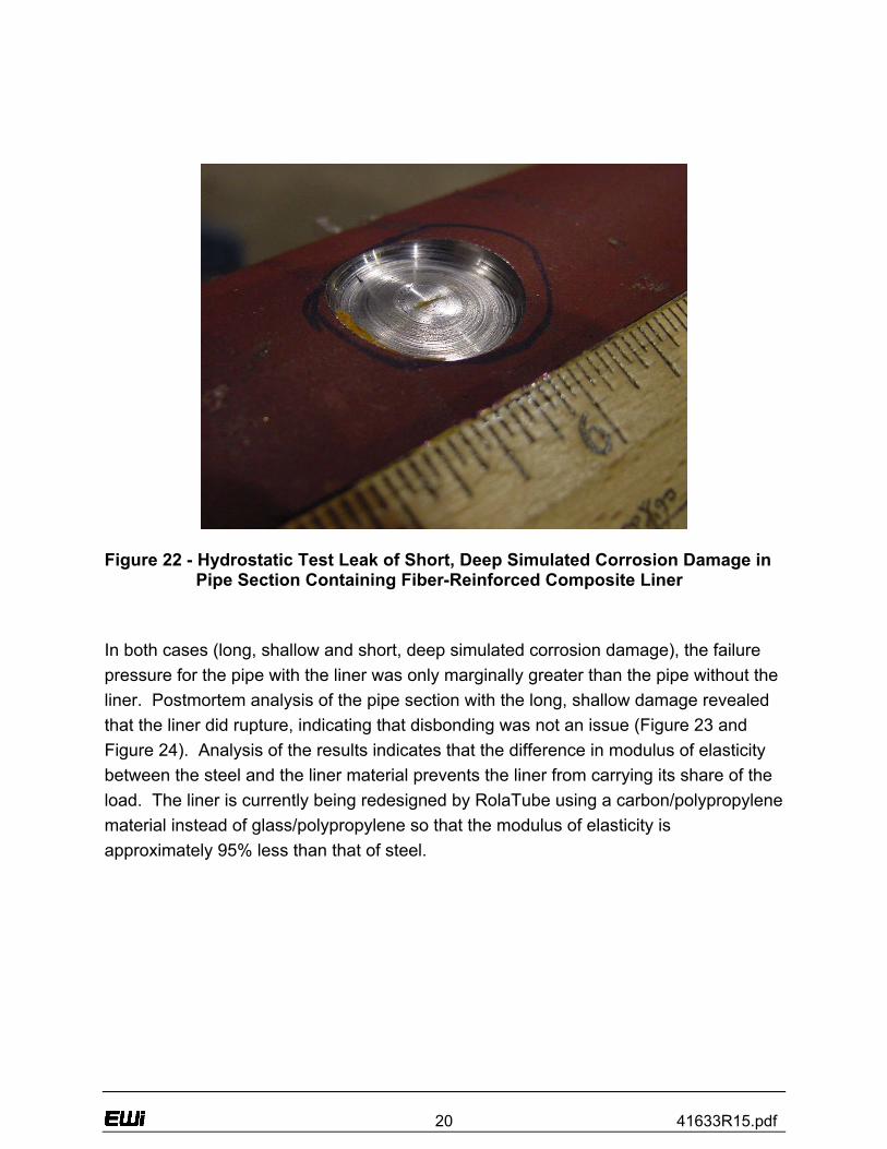
Figure 22 - Hydrostatic Test Leak of Short, Deep Simulated Corrosion Damage in
Pipe Section Containing Fiber-Reinforced Composite Liner In both cases (long, shallow and short, deep simulated corrosion damage), the failure pressure for the pipe with the liner was only marginally greater than the pipe without the liner. Postmortem analysis of the pipe section with the long, shallow damage revealed that the liner did rupture, indicating that disbonding was not an issue (Figure 23 and Figure 24). Analysis of the results indicates that the difference in modulus of elasticity between the steel and the liner material prevents the liner from carrying its share of the load. The liner is currently being redesigned by RolaTube using a carbon/polypropylene material instead of glass/polypropylene so that the modulus of elasticity is approximately 95% less than that of steel.
21 41633R15.pdf
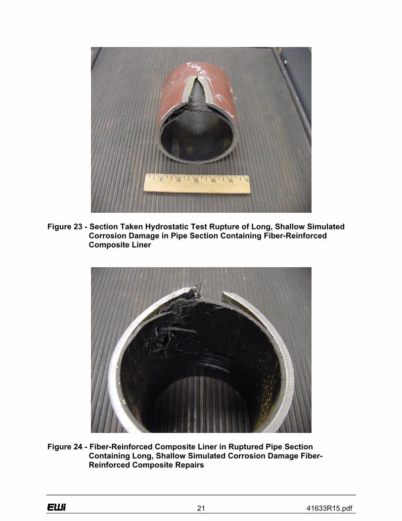
Figure 23 - Section Taken Hydrostatic Test Rupture of Long, Shallow Simulated
Corrosion Damage in Pipe Section Containing Fiber-Reinforced Composite Liner
Figure 24 - Fiber-Reinforced Composite Liner in Ruptured Pipe Section
Containing Long, Shallow Simulated Corrosion Damage Fiber-Reinforced Composite Repairs
22 41633R15.pdf
During the next reporting period, additional small-scale experiments will be carried out using the redesigned fiber-reinforced composite liner material following the receipt of samples of lined pipe from RolaTube. Should the performance of this repair method continue to be less than desirable, the use of another type of liner-based repair, such as solid expandable tubulars, will be considered. Subtask 4.3 - Simulation and Analysis of Potential Repair Methods In previous work for PRCI,(6) finite element analysis (FEA) was performed to simulate external weld deposition repair of internal wall loss. To supplement this work, plans were made for additional FEA to simulate internal weld deposition repair of external wall loss. During this reporting period and prior to the initial trials for fiber-reinforced composite repairs, FEA was performed by RolaTube to determine the required properties of the liner material. Again, postmortem analysis of the pipe section damage indicates that the difference in modulus of elasticity between the steel and the liner material prevents the liner from carrying its share of the load. RolaTube is currently using FEA to redesign the liner with a carbon/polypropylene material instead of glass/polypropylene material. For the next reporting period, EWI will conduct FEA where appropriate, to model the welding repair methods and guide the baseline parameters for the weld repair development trials. An example such FEA work would be to model the relationship between weld heat input and the temperature on the outside surface of the pipe to predict the behavior of the pipe coating. Subtask 4.4 - Internal Repair Evaluation Trials During this reporting period, all of the experimental work pertaining to the evaluation of potential repair methods has focused on fiber-reinforced composite repairs. During the next reporting period, areas of damage will be artificially introduced into sections of pipe using methods previously developed at EWI. The artificially introduced damage will then be repaired using mechanized gas metal arc welding (GMAW). Repairs will be made while the pipe sections are contained within a soil box so that the ability of the soil to remove heat from the pipe wall is simulated. The pipe sections will consist of older vintage line pipe material, typical of pipelines currently in service that
23 41633R15.pdf
frequently require repair. A supply of material that fits this description is currently on hand at EWI. The diameters of these materials range from 508 to 914 mm (20 to 36 in.). All significant data pertinent to each repair method (e.g., welding parameters, etc.) will be recorded during the development trials. Following the completion of the repairs, metallographic examination and mechanical testing will be carried out. The effect of temperature on the integrity of external coatings will then be investigated. A limited number of hydrostatic burst tests will also be carried out. Subtask 4.5 - Prepare Report "Review and Evaluation of Internal Pipeline Repair Technologies" Again, during this reporting period preliminary experimental work was conducted to produce data for this report. During the next reporting period, EWI will produce the Task 4.0 - Evaluation of Potential Repair Methods draft report containing a detailed analysis of the development trial results. The report will include a matrix listing capabilities and/or limitations of each repair method, and recommendations of potential repair methods that should be included in the next phase of the project. Task 5.0 - Optimize and Validate Internal Repair Methods Task 4.0 is prerequisite to Task 5.0, therefore, no activity occurred during this reporting period. During the next reporting period, preliminary plans will be made for this task, which will involve optimizing the most promising repair technologies and verifying pipeline performance by full-scale tests.
24 41633R15.pdf
5.0 - CONCLUSIONS The most common cause for repair of gas transmission pipelines is external, corrosion-caused loss of wall thickness.(7) To prevent an area of corrosion damage from causing a pipeline to rupture, the area containing the corrosion damage must be reinforced. Other pipeline defects that commonly require repair include internal corrosion, original construction flaws, service induced cracking, and mechanical damage. Defects oriented in the longitudinal direction have a tendency to fail from hoop stress (pressure loading) and must be reinforced in the circumferential direction. Defects oriented in the circumferential direction have a tendency to fail from axial stresses (e.g., pipeline settlement) and must be reinforced in the longitudinal direction. Full-encirclement steel repair sleeves resist hoop stress and, if the ends are welded to the pipeline, can also resist axial stresses. The Task 2.0 - Technology Status Assessment indicates that the most commonly used method for repair of gas transmission pipelines is the full-encirclement steel repair sleeve (Figure 1). This and other repair methods commonly applied from the outside of the pipeline are typically done so while the pipeline remains in-service. While this would be desirable for internal repair, many of the repair methods that are applicable to the inside of the pipeline would require that the pipeline be taken out-of-service. Most of the repair methods that are commonly applied to the inside of other types of pipelines, which typically operate at low pressure, are done so to restore leak tightness. These repair methods would require further development in order for them to restore the strength of a gas transmission pipeline. The two broad categories of deposited weld metal repair and fiber-reinforced composite repair technologies were identified for potential application for internal repair of gas transmission pipelines. Both are used to some extent for other applications and could be further developed for internal, local, structural repair of gas transmission pipelines. The specific development needs for these repair technologies can be summarized as follows. The important characteristics of a useful internal weld repair system include the ability to operate at long range from the pipe entry point (i.e., 2,000 ft. or more), the agility to transverse bends and miters, a machining capability to prepare the weld joint, a grinding system for cleaning and preparation, and a high deposition robust welding process.
25 41633R15.pdf
Although many of these features are incorporated in the existing systems, there is no single system that possesses all the required characteristics. Further work is required to develop a system with all of these features. Further development of fiber-reinforced composite repairs/liners with sufficient strength is required prior to application to internal, local structural repair of gas transmission pipelines. Ideally, these products would combine the strength of currently used external repair products or composite reinforced line pipe (CRLP) with the installation process currently used for liners in other types of pipelines. Adhesion of the liner to the pipe surface, which is important for structural reinforcement but not restoration of leak tightness, also needs to be addressed. The required thickness of a repair for structural reinforcement and the potentially adverse effect on internal inspection and flow restriction is another issue to be addressed.
26 41633R15.pdf
6.0 - REFERENCES (1) Kiefner, J. F. and Vieth, P. H., "A Modified Criterion for Evaluating the Remaining
Strength of Corroded Pipe" Final Report to A.G.A. Pipeline Corrosion Supervisory Committee, Project PR-3-805, Battelle, Columbus, OH, December 1989.
(2) Gordon, J. R., Bruce, W. A., and Porter, N. C., “Internal Repair of Pipelines –
Research Management Plan,” Report to National Energy Technology Laboratory, U.S. Department of Energy, DOE Award No.: DE-FC26-02NT41633, Edison Welding Institute, October 2002.
(3) Gordon, J. R., Bruce, W. A., Sullivan, M., and Neary, C. M., “Internal Repair of
Pipelines – Technology Status Assessment,” Report to National Energy Technology Laboratory, U.S. Department of Energy, DOE Award No.: DE-FC26-02NT41633, Edison Welding Institute and Pacific Gas & Electric, November 2002.
(4) Bruce, W. A., “Welding onto In-Service Thin Wall Pipelines,” Final Report for EWI
Project No. 41732CAP to PRC International, Contract No PR-185-9908, July 2000. (5) Kiefner, J. F., Barnes, C. R., Gertler, R. C., Fischer, R. D., and Mishler, H. W.,
“Experimental Verification of Hot Tap Welding Thermal Analysis. Final Report - Phase II - Volume 2, Liquid Propane Experiments,” Repair and Hot Tap Welding Group, Battelle Columbus Laboratories, May 1983.
(6) Wang, Y.-Y., and Bruce, W. A., “Examination of External Weld Deposition Repair
for Internal Wall Loss,” Final Report for EWI Project No. 07723CAP to PRC International, Contract No PR-185-9633, March 1998.
(7) Eiber, R. J., Bubenik, T. A., and Leis, B. N., "Pipeline Failure Mechanisms and
Characteristics of the Resulting Defects," Eighth Symposium on Line Pipe Research, Paper No. 7 (Houston, TX: American Gas Association, 1993).
27 41633R15.pdf
7.0 - BIBLIOGRAPHY Bruce, W. A., “Welding onto In-Service Thin Wall Pipelines,” Final Report for EWI
Project No. 41732CAP to PRC International, Contract No PR-185-9908, July 2000. This report discusses special welding difficulties and the extra care required to ensure safe operating procedures and sound welds due to repairs and modifications to in-service, thin walled pipelines.
Eiber, R. J., Bubenik, T. A., and Leis, B. N., "Pipeline Failure Mechanisms and
Characteristics of the Resulting Defects," Eighth Symposium on Line Pipe Research, Paper No. 7 (Houston, TX: American Gas Association, 1993). This report discusses four broad categories of pipeline failure mechanisms: outside forces, environmentally induced defects, manufacturing/materials defects, and operator error or miscellaneous defects.
Gordon, J. R., Bruce, W. A., and Porter, N. C., “Internal Repair of Pipelines – Research
Management Plan,” Report to National Energy Technology Laboratory, U.S. Department of Energy, DOE Award No.: DE-FC26-02NT41633, Edison Welding Institute, October 2002. This plan contains a concise summary of the technical objectives and approach for each task. The document also contain detailed schedules and planned expenditures for each task and all major milestones and decision points for the two year project duration.
Gordon, J. R., Bruce, W. A., Sullivan, M., and Neary, C. M., “Internal Repair of Pipelines
– Technology Status Assessment,” Report to National Energy Technology Laboratory, U.S. Department of Energy, DOE Award No.: DE-FC26-02NT41633, Edison Welding Institute and Pacific Gas & Electric, November 2002. This report presents the status of existing pipeline repair technology that can be applied to the inside of gas transmission pipelines, and includes results from a comprehensive computerized literature search, together with information obtained from discussions with companies that are currently developing or evaluating novel pipeline repair methods.
Kiefner, J. F., Barnes, C. R., Gertler, R. C., Fischer, R. D., and Mishler, H. W.,
“Experimental Verification of Hot Tap Welding Thermal Analysis. Final Report - Phase II - Volume 2, Liquid Propane Experiments,” Repair and Hot Tap Welding Group, Battelle Columbus Laboratories, May 1983. This report documents the
28 41633R15.pdf
verification of two thermal analysis models of hot tap welding on pressurized pipelines. With velocity input modified as shown, the models are capable of predicting maximum temperatures in the pipe wall especially at the inside surface and critical cooling rates in the heat-affected zones within the range of heat inputs that are practical for shielded metal arc welding.
Kiefner, J. F. and Vieth, P. H., "A Modified Criterion for Evaluating the Remaining
Strength of Corroded Pipe" Final Report to A.G.A. Pipeline Corrosion Supervisory Committee, Project PR-3-805, Battelle, Columbus, OH, December 1989. This report documents a modified criterion for evaluating the corrosion level of a pipeline based on pipeline stress calculations (available as a PC program) as a less conservative alternative to ANSI / ASME B31G.
Wang, Y.-Y., and Bruce, W. A., “Examination of External Weld Deposition Repair for
Internal Wall Loss,” Final Report for EWI Project No. 07723CAP to PRC International, Contract No PR-185-9633, March 1998. This report discusses the deposition of weld metal on the external surface of straight sections of pipe, field bends, tees and elbows as a potentially useful method for in-service repair of internal wall loss.
29 41633R15.pdf
8.0 - LIST OF ACRONYMS
ASME American Society of Mechanical Engineers ANSI American National Standards Institute CAE Computer Aided Engineering
CRLP Composite Reinforced Line Pipe DOE Department of Energy EWI Edison Welding Institute FEA Finite Element Analysis
FRCP Fiber-Reinforced Composite Pipe Glass-HDPE Glass-High Density Polyethylene
GMAW Gas Metal Arc Welding HDPE High Density Polyethylene
IR Infra-Red NDE Nondestructive Evaluation NETL National Energy Technology Laboratory OD Outside Diameter PC Personal Computer
PG&E Pacific Gas & Electric PRCI Pipeline Research Council International
30 41633R15.pdf
9.0- APPENDICES
.
31 41633R15.pdf
Appendix A
Draft Industry Survey with Cover Letter
A-1
1250 Arthur E. Adams Drive • Columbus, Ohio 43221 • (614) 688-5000 • (614) 688-5001 • http://www.ewi.org/
April 11, 2003 <<<FIELD 1>>> EWI Project No. 46211GTH, “Internal Repair of Pipelines” Dear <<<FIELD 2>>>: Enclosed is a survey of operator experience and industry needs pertaining to internal repair of pipelines. EWI is conducting this survey as part of a project being funded by the National Energy Technology Laboratory. The objectives of this project are to evaluate, develop, demonstrate, and validate internal repair methods for pipelines. Please complete this survey at your earliest convenience.1 Your participation is greatly appreciated. If you have questions or require additional information, please contact me at 614-688-5059 or [email protected] Sincerely, William A. Bruce, P.E. Principal Engineer Materials section Enclosure
1 A copy of this survey was also sent to <<<FIELD 3>>> at your company. You may want to coordinate your response.
A-2 41633R15.pdf
April 11, 2003 EWI Project No. 46211GTH
Internal Repair of Pipelines Survey of Operator Experience
and Industry Needs
conducted for:
National Energy Technology Laboratory Morgantown, WV
A-3 41633R15.pdf
Project No. 46211GTH
on
Internal Repair of Pipelines – Survey of Operator Experience and Industry Needs
for
National Energy Technology Laboratory Morgantown, WV
April 11, 2003
EWI 1250 Arthur E. Adams Drive
Columbus, OH 43221
A-4 41633R15.pdf
Internal Repair of Pipelines – Survey of Operator Experience and Industry Needs
1.00 Introduction
A repair method that can be applied from the inside of a gas transmission pipeline (i.e., a trenchless repair) is an attractive alternative to conventional repair methods since the need to excavate the pipeline is precluded. This is particularly true for pipelines in environmentally sensitive and highly populated areas. Several repair methods that are commonly applied from the outside of the pipeline are, in theory, directly applicable from the inside. However, issues such as development of the required equipment to perform repairs remotely and mobilization of equipment through the pipeline to areas that require repair need to be addressed. Several additional repair methods that are commonly applied to other types of pipelines (gas distribution lines, water lines, etc.) also have potential applicability for internal repair of gas transmission pipelines. Many of these require further development to meet the requirements for repair of gas transmission pipelines. The objectives of a project being funded by the National Energy Technology Laboratory are to evaluate, develop, demonstrate, and validate internal repair methods for pipelines; develop a functional specification for an internal pipeline repair system; and prepare a recommended practice for internal repair of pipelines. One of the initial tasks of this project involves conducting a survey to determine the repair needs and performance requirements for internal pipeline repairs. The purpose of this survey is to better understand the needs of the natural gas transmission industry regarding internal repair.
2.00 Instructions Please respond as completely as possible to as many questions as possible. Space is also provided for any comments that you may have.
3.00 Survey 3.1 Part 1 – Currently-Used Repair Methods
1. Has your company experienced degradation (corrosion, cracking, etc) of a transmission line?
If so, has your company replaced or repaired pipe because of degradation?
2. What specific repair methods would typically be used to repair different types of
degradation?
A-5 41633R15.pdf
3.
Comments pertaining to currently-used repair methods – 3.2 Part 2 – Use/Potential Use of Internal Repair
1. Has your company attempted repair of a transmission line from inside the pipe?
If so, describe the repair(s)
2. There are many factors that affect the decision to repair or replace pipe. What circumstances would favor performing a repair from inside the pipe using only one or two excavations rather than excavating the entire length of pipe?
3. If the technology were available to perform a repair from the inside, would your
company consider using the technology?
If so, for what application(s) – e.g., specific geographic locations and special situations?
4. At least one excavation will be required to insert the internal repair device into the
pipe. From this excavation, the repair device could be travel in each direction from the excavation. About how far from the insertion point should the repair device be able to travel?
What range of pipe diameters should the repair device be capable of operation in?
5. What potential obstructions such as elbows, bends, branches, and taps should the
repair system be able to negotiate?
6. Comments pertaining to the use/potential use of internal repair –
A-6 41633R15.pdf
3.3 Part 3 – Need for In-Service Internal Repair
1. How important is the ability to perform a repair from the inside the pipe while the pipeline remains in service?
2. Would internal repair remain attractive if it was necessary to completely shut down
the pipeline (depressurized and evacuated) during the repair?
Depressurized but not evacuated?
Out of service (no flow) but remain pressurized?
3. Comments pertaining to the need for in-service internal repair – 3.4 Part 4 – Applicable Types of Damage
1. What types of external coatings would be found on transmission lines owned by your company?
2. If a repair involving welding from the inside was performed, how important is it to
preserve the integrity of the coating?
Is your cathodic protection system capable of compensating for relatively small breaches in the coating?
3.
Comments pertaining to applicable types of damage – 3.5 Part 5 – Operational and Performance requirements for Internal Repairs
1. Two general categories of repairs are being considered, (1) using weld metal to restore a surface and (2) installing an internal sleeve, either metallic or nonmetallic,
A-7 41633R15.pdf
to provide structural reinforcement of leak tightness. Is it important that the line remain inspectable by pigging after repair?
About how far could the repair protrude into the pipe before it would interfere with pigging?
2. What NDE would your utility require for a repair to an existing longitudinal or
circumferential weld?
Could a visual or magnetic particle examination be substituted for radiography in these special circumstances?
What NDE would your utility require for a welded repair to base metal (e.g. corrosion pitting)?
3. Would the use of internal repair be attractive even if it were considered a temporary
repair
4. Comments pertaining to operational and performance requirements for internal repairs – 3.6 General Comments Please provide any general comments that you may have.
Appendix B
Members of the Pipeline Research Council International
B-1
Members of the Pipeline Research Council International Advantica Technologies Ltd BP Buckeye Pipe Line Company Chevron Texaco Pipeline Company CMS Panhandle Companies Colonial Pipeline Company Columbia Gas Transmission Co. ConocoPhillips Consumers Energy Dominion Transmission Duke Energy Gas Transmission El Paso Corporation Enbridge Pipelines Enron Transportation Services Corp. Explorer Pipeline Company ExxonMobil Pipeline Company Foothills Pipe Lines Ltd Gassco A.S. (Norway) Gasum Oy (Finland) Gaz de France Gulf South Pipeline Marathon Ashland Pipe Line LLC N.V. Nederlandse Gasunie/Gastransport Services (The Netherlands) National Fuel Gas Supply Corporation Saudi Aramco Sempra Energy Utilities/Southern California Gas Company Shell Pipeline Company LP Southern Natural Gas Company TEPPCO TransCanada PipeLines Limited Transco (UK) TransGas Williams Gas Pipeline
Appendix C
List of Natural Gas Pipeline Operating Companies
(from http://www.ferc.gov/gas/pipecomp.htm)
C-1
List of Natural Gas Pipeline Operating Companies
Algonquin Gas Transmission Company Algonquin LNG, Inc. ANR Pipeline Company ANR Storage Company Black Marlin Pipeline Company Blue Lake Gas Storage Company Canyon Creek Compression Company Carnegie Interstate Pipeline Company Chandeleur Pipe Line Company Colorado Interstate Gas Company Columbia Gas Transmission Corporation Columbia Gulf Transmission Company Cove Point LNG Limited Partnership Crossroads Pipeline Company Discovery Gas Transmission LLC Dominion Transmission Inc. Dynegy Midstream Pipeline, Inc. East Tennessee Natural Gas Company Egan Hub Partners, L.P. El Paso Natural Gas Company Equitrans, Inc. Florida Gas Transmission Company Gas Transport, Inc. Granite State Gas Transmission, Inc. Great Lakes Gas Transmission Limited Partnership Gulf South Pipeline Gulf States Transmission Corporation High Island Offshore System Iroquois Gas Transmission System, L.P. Kansas Pipeline Company Kentucky West Virginia Gas Company Kern River Gas Transmission Company KM Interstate Gas Transmission Co. KN Wattenberg Transmission Maritimes & Northeast Pipeline L.L.C. Michigan Gas Storage Company Midwestern Gas Transmission Company MIGC, Inc. Mississippi River Transmission Corporation Mojave Pipeline Company National Fuel Gas Supply Corporation Natural Gas Pipeline Company of America Nora Transmission Company Northern Border Pipeline Company Northern Natural Gas Company
C-2
Northwest Pipeline Corporation OkTex Pipeline Company Overthrust Pipeline Company Ozark Gas Transmission System Paiute Pipeline Company Panhandle Eastern Pipe Line Company Petal Gas Storage Company PG&E Gas Transmission-Northwest Corporation Questar Pipeline Company Reliant Energy Gas Transmission Company Sabine Pipe Line Company Sea Robin Pipeline Company Shell Offshore Pipelines South Georgia Natural Gas Company Southern Natural Gas Company Southwest Gas Storage Company Steuben Gas Storage Company TCP Gathering Co. Tennessee Gas Pipeline Company Texas Eastern Transmission Corporation Texas Gas Transmission Corporation Total Peaking LLC Trailblazer Pipeline Company TransColorado Gas Transmission Company Transcontinental Gas Pipe Line Corporation Transwestern Pipeline Company Trunkline Gas Company Trunkline LNG Company Tuscarora Gas Transmission Company U-T Offshore System Vector Pipeline Venice Gathering System, L.L.C. Viking Gas Transmission Company Williams Gas Pipelines Central, Inc. Williston Basin Interstate Pipeline Company Wyoming Interstate Company, Ltd. Young Gas Storage Company, Ltd.