internal model controller design for a robot arm by vishal kumar advisor: gary l. dempsey 5/6/08...
Post on 22-Dec-2015
213 views
TRANSCRIPT

Internal Model Controller Design for a Internal Model Controller Design for a Robot armRobot arm
By Vishal KumarBy Vishal KumarAdvisor: Gary L. DempseyAdvisor: Gary L. Dempsey
5/6/085/6/08Bradley UniversityBradley University
Department of Computer and Electrical EngineeringDepartment of Computer and Electrical Engineering
Senior Project

Senior ProjectSenior Project
1.1. Functional DescriptionFunctional Description
2.2. Project FocusProject Focus
3.3. Functional Requirements and Functional Requirements and SpecificationsSpecifications
4.4. Lab work and comparison of resultsLab work and comparison of results

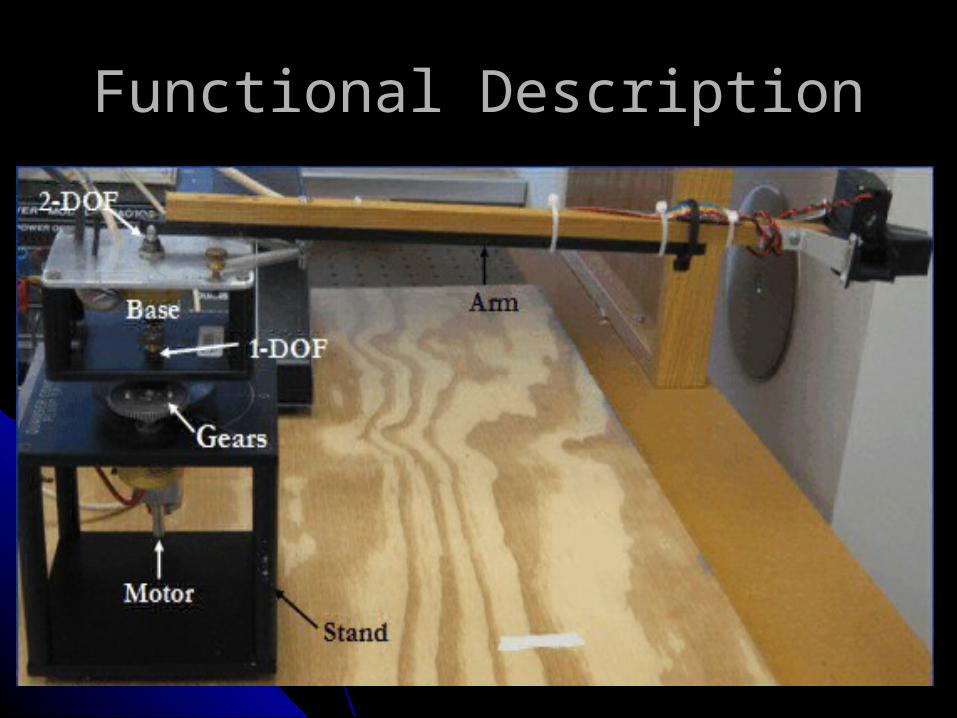
Functional DescriptionFunctional Description
Individual ComponentsIndividual Components
• 1.46 GHz Windows Based PC with plenty 1.46 GHz Windows Based PC with plenty of RAMof RAM
• Quanser Plant SRV-02 with embedded Quanser Plant SRV-02 with embedded position sensors, gripper and motorposition sensors, gripper and motor
• Q8 High-Performance H.I.L Control Board Q8 High-Performance H.I.L Control Board and I/O port interfaceand I/O port interface
• Power Module PAO103Power Module PAO103
Functional DescriptionFunctional Description

Functional DescriptionFunctional DescriptionQ8 High-Performance H.I.L Control BoardQ8 High-Performance H.I.L Control Board
8 A/D / 8 D/ASimultaneous Sampling of all A/D and Simultaneous Update to all D/ASupported by Real-Time Targets – RTX, xPC
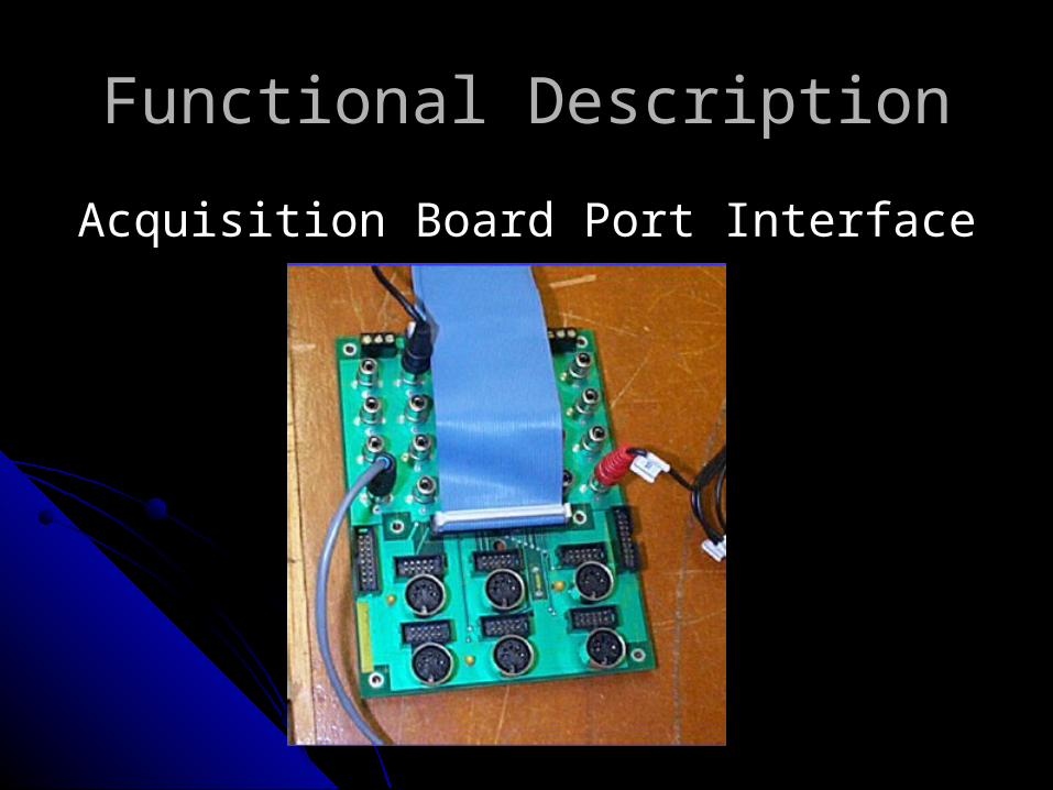
Functional DescriptionFunctional Description
Acquisition Board Port InterfaceAcquisition Board Port Interface

Functional DescriptionFunctional Description
Power ModulePower Module

High Level System Block DiagramHigh Level System Block Diagram

Project AbstractProject Abstract
The goal of this Electrical Engineering Senior Capstone Project is to design a Internal Model Controller for controlling the non-linear 6th order Quanser Plant in the level configuration.
The disturbance rejection capability of Internal Model Control architecture is capable of controlling high-order plants despite their non-linearities and external disturbances.

Project DescriptionProject Description
Internal Model Control Open-LoopInternal Model Control Open-Loop
Let Gp(s) = approx(Gp(s))And Gc(s) = approx(Gp(s)) ^ -1Then Gp(s)*Gc(s) = approx(Gp(s)) * approx(Gp(s)) ^ -1 = 1

Project DescriptionProject Description
Internal Model Control Closed-LoopInternal Model Control Closed-Loop

Project DescriptionProject Description
Internal Model Control AdvantagesInternal Model Control Advantages Provides time-delay compensationProvides time-delay compensation
At steady-state, the controller will give offset free At steady-state, the controller will give offset free responses(perfect control at S.S)responses(perfect control at S.S)
The controller can be used to shape both the input tracking and The controller can be used to shape both the input tracking and disturbance rejection responsesdisturbance rejection responses
The controller is the inverse of the plant without non-invertible The controller is the inverse of the plant without non-invertible components(time-delay)components(time-delay)
Perfect Tracking is achieved despite model-mismatch, as long Perfect Tracking is achieved despite model-mismatch, as long as the controller is the perfect inverse of the model. as the controller is the perfect inverse of the model.

Project DescriptionProject Description
Model Implementation TechniquesModel Implementation Techniques22ndnd order model(Linear) order model(Linear) used for used for
Proj. Proj. Look-up Tables(Linear and Non-Linear)Look-up Tables(Linear and Non-Linear)State-Space Model(Linear)State-Space Model(Linear)Adaline model(Linear)Adaline model(Linear)Non-Linear Perceptron model(Non Non-Linear Perceptron model(Non
Linear)Linear)

PrespectivePrespective
What makes this project different?What makes this project different?
New ToolsNew Tools• Simulink/Real Time Execution(RTX) Simulink/Real Time Execution(RTX)
WorkshopWorkshop• WinCon Client and WinCon Server WinCon Client and WinCon Server
environmentenvironment• Implementing an advanced controller Implementing an advanced controller
architecture – IMC – basis for adaptive controlarchitecture – IMC – basis for adaptive control

ApplicationsApplications
Adaptive Signal ProcessingAdaptive Signal ProcessingFlight Control – Adaptive models are of Flight Control – Adaptive models are of
importanceimportanceHydraulics – disturbance rejection is of Hydraulics – disturbance rejection is of
importanceimportance

Functional RequirementsFunctional Requirements
1.1. Single Loop – Proportional , Single Loop – Proportional , Proportional–Derivative ControllerProportional–Derivative Controller
2.2. FD Design for P, PD, PI controllersFD Design for P, PD, PI controllers
3.3. Internal Model ControlInternal Model Control
4.4. Internal Model Control with Adaptive Internal Model Control with Adaptive ModelModel

Performance SpecificationsPerformance Specifications
Percent Overshoot Percent Overshoot 5% max5% maxTime to PeakTime to Peak 50ms max50ms maxTime to settle Time to settle 200ms max200ms maxClosed Loop Bandwidth Closed Loop Bandwidth 2Hz min2Hz minClosed Loop Frequency Resp.Closed Loop Frequency Resp. 3dB max 3dB maxGain Margin Gain Margin 5.0 min5.0 minPhase Margin Phase Margin 60 degrees 60 degrees
minminSteady State Error Steady State Error 1 degree max1 degree maxController Execution Time Controller Execution Time 1ms max1ms max

Fall ’07 WorkFall ’07 Work
System Identification without armSystem Identification without arm
)150/(
69)(
)35(
ss
esGp
mss Experimental
Simulation

Fall ’07 WorkFall ’07 Work
Proportional Controller Design without Proportional Controller Design without armarm
Gc(s) = K = 0.3Gc(s) = K = 0.3
1.5 1.55 1.6 1.65 1.7 1.75-5
0
5
10
15
20
25
30
35
Time
Deg
rees
Proportional ControlGc(s) = .3

Fall ’07 WorkFall ’07 WorkProportional – Derivative Controller Design Proportional – Derivative Controller Design
without armwithout armGc(s) = 0.61(s + 61.5)/(s+120)Gc(s) = 0.61(s + 61.5)/(s+120)

Spring ‘08 WorkSpring ‘08 Work
System Identification with ArmSystem Identification with Arm
45.73 e^ ( -0.110s)45.73 e^ ( -0.110s)
Gp(s) = --------------------------Gp(s) = --------------------------
s(s/30.0 +1.0)s(s/30.0 +1.0)
Gain and Delay found by experimental dataGain and Delay found by experimental data
Pole found by multiple simulation best fit methodPole found by multiple simulation best fit method
This is the best fit 2This is the best fit 2ndnd order model for the plant. order model for the plant.
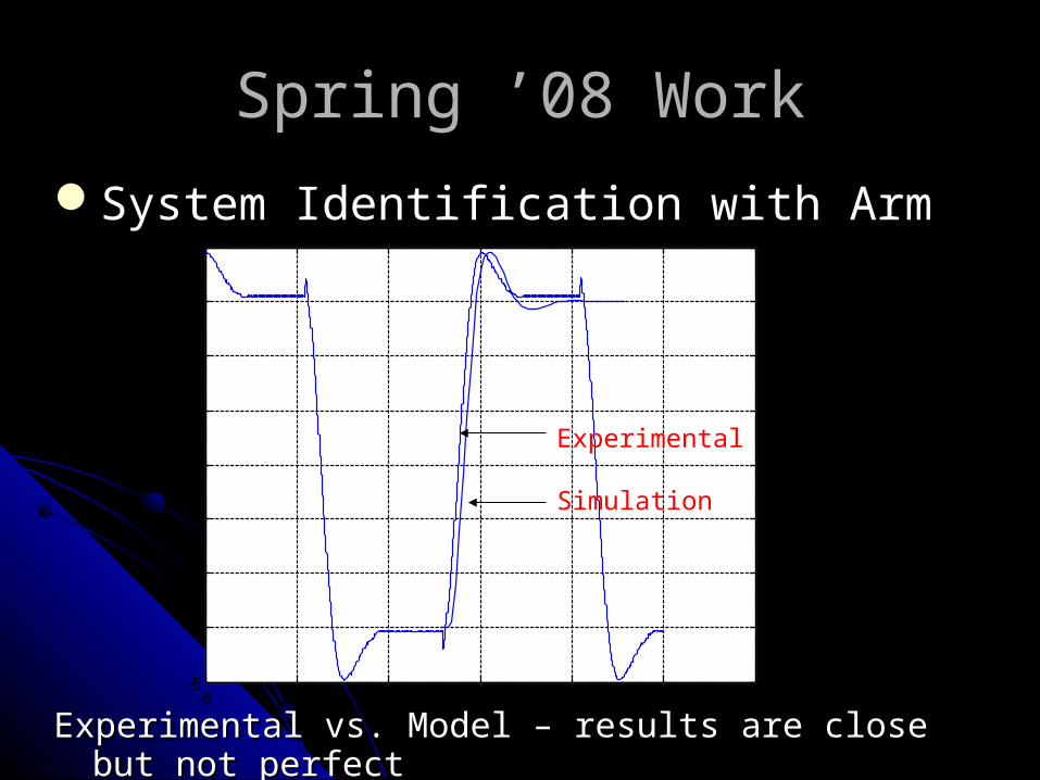
System Identification with ArmSystem Identification with Arm
Experimental vs. Model – results are close but not perfectExperimental vs. Model – results are close but not perfect
Spring ’08 Work
0 1 2 3 4 5 6-5
0
5
10
15
20
25
30
35
Experimental
Simulation

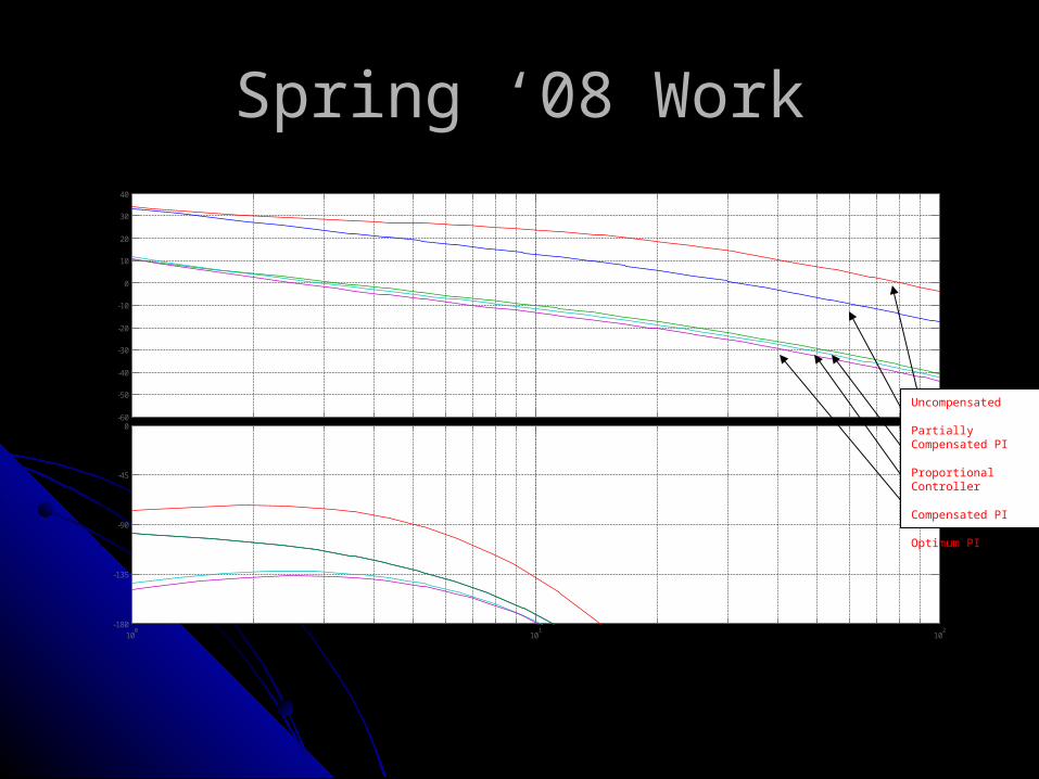
Spring ‘08 WorkSpring ‘08 Work
F.D.Design – P controllerF.D.Design – P controllerF.D. Design – PD controllerF.D. Design – PD controllerF.D. Design – PI controllerF.D. Design – PI controllerF.D. Design – Optimum Phase Margin PI F.D. Design – Optimum Phase Margin PI
controllercontroller
Standard Classical Control TechniquesStandard Classical Control Techniques
Design, Simulate, Implement, EvaluateDesign, Simulate, Implement, Evaluate
Spring ‘08 WorkSpring ‘08 Work
-60
-50
-40
-30
-20
-10
0
10
20
30
40
Mag
nitu
de (
dB)
100
101
102
-180
-135
-90
-45
0
Pha
se (
deg)
Bode Diagram
Frequency (rad/sec)
Uncompensated
Partially Compensated PI
Proportional Controller
Compensated PI
Optimum PI

Spring ‘08 WorkSpring ‘08 Work
IMC Controller Design

Spring ‘08 WorkSpring ‘08 Work•Final Design by Tuning

Spring ‘08 WorkSpring ‘08 Work
IMC step Response
Spring ‘08 WorkSpring ‘08 Work
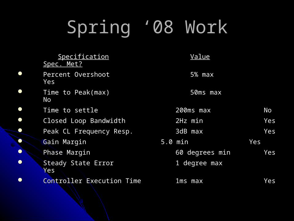
SpecificationSpecification ValueValue Spec. Spec. Met?Met?
Percent Overshoot Percent Overshoot 5% max5% max YesYes
Time to Peak(max) Time to Peak(max) 50ms max50ms max NoNo
Time to settleTime to settle 200ms max200ms max NoNo
Closed Loop Bandwidth Closed Loop Bandwidth 2Hz min2Hz min YesYes
Peak CL Frequency Resp.Peak CL Frequency Resp. 3dB max3dB max YesYes
Gain MarginGain Margin 5.0 min5.0 min YesYes
Phase MarginPhase Margin 60 degrees min60 degrees min YesYes
Steady State ErrorSteady State Error 1 degree max1 degree max YesYes
Controller Execution TimeController Execution Time 1ms max1ms max YesYes
ConclusionConclusion
Internal Model Control(IMC) provides excellent performance for stable Internal Model Control(IMC) provides excellent performance for stable plants. Due to a integration in the plant model, meaning that the plants. Due to a integration in the plant model, meaning that the plant is marginally stable/unstable, the controller architecture plant is marginally stable/unstable, the controller architecture reaches limitations and has to be modified. reaches limitations and has to be modified.
As shown above, in the Simulink Block Diagram, the new architecture As shown above, in the Simulink Block Diagram, the new architecture provides velocity and position feedback with Internal Model for the provides velocity and position feedback with Internal Model for the velocity of the plant. Literature analyzing controller design provides velocity of the plant. Literature analyzing controller design provides no insight for controlling unstable plants. no insight for controlling unstable plants.
The aforementioned technique has powerful implications for controlling The aforementioned technique has powerful implications for controlling unstable plants using the IMC architecture. unstable plants using the IMC architecture.

Questions? Comments?Questions? Comments?