internal components / interne komponenter · · 2013-02-27internal components / interne...
TRANSCRIPT

Internal Components / Interne Komponenter Index / Indhold
1.0Date: Made By: Approved By: Rev. no. Section:
Dato: Udarb. af: Godk. af: Rev. nr. Sektion:12/06/09 RO'C PEB 004 02
w w w . l o g s t r u p . c o m
DESCRIPTION / BENÆVNELSE PAGE / SIDE
Introduction / Introduktion ............................................................................................................................................. 2.0
ORDERING INFORMATION / BESTILLINGSINFORMATION
Forms of Separation / Adskillelsesformer.................................................................................................................... 3.0Base Cover, Front Plate and Blankplates / Bundafdækning, Frontplade og Blindplader ............................................ 6.0Bottom Cover Plate and End Cover / Bundafdækningsplade og Endeplade ............................................................... 7.0Side Plates type EPC / Sideplader type EPC.............................................................................................................. 8.0Vent Plates and Vent Flaps/ Ventilationssideplader og Klapper ................................................................................. 9.0Front and Rear Cover Plates/ Front- og Bagside Afdækningsplader ........................................................................... 10.0Rear Cover Plate (Release) & Release Cover / Bagside Afdækning (Release) og Release Afdækning ..................... 11.0Rear Cover Plates (Cableway) / Bagside Afdækningsplader (Kabelsektion) ............................................................... 12.0Partition Plates and Brackets / Skilleplader og Beslag................................................................................................. 13.0Joint Brackets and Stop End Plates / Samlebeslag og Afslutningsplader.................................................................... 14.0Explosion Duct / Eksplosionskanal............................................................................................................................... 15.0Explosion Flap / Eksplosionsklap ................................................................................................................................. 16.0Main Busbar Cover and Cover Plates / Samleskinneafdækning og Afdækningsplader............................................... 17.0Mounting plates and brackets / Montageplader og beslag ........................................................................................... 18.0Dividing Plates / Skilleplader ........................................................................................................................................ 19.0Mounting Plates type ETM and Brackets / Montageplader type ETM og Beslag ......................................................... 20.0Cross Hole Bars / Krydshulsbeslag .............................................................................................................................. 22.0Compartment Boxes / Montagekasser ......................................................................................................................... 23.0Meter Unit / Målerfelt.................................................................................................................................................... 24.0M.C.B Units / Indsats for gruppematerie ...................................................................................................................... 28.0Bending Tools / Bukkeværktøj...................................................................................................................................... 32.0
ASSEMBLY INSTRUCTIONS / MONTAGEVEJLEDNINGER
Sideplates / Sideplader................................................................................................................................................. 33.0Compartment Boxes / Montagekasser ......................................................................................................................... 34.0
TERMINOLOGY & DIMENSIONS / TERMINOLOGI & MALSÆTNING
Functional Units, Cableways and Explosion Sections / Funktionsenheder, Kabel - og Eksplosionssektioner............. 36.0

Internal Components / Interne KomponenterIntroduction / Introduktion
2.0 Section: Rev. no. Approved By: Made By: Date:
Sektion: Rev. nr. Godk. af: Udarb. af: Dato:02 003 JLI RO'C 02/06/10
INTRODUCTION This section contains the internalcomponents in the Logstrup modularsystem.The internal components enableenclosures to be divided into 4 separatesections.1. Explosion / Ventilation sections2. Functional unit sections3. Busbar sections4. Cable waysThe forms of separation between thesesections may be varied depending on theapplication to improve the safety level ofthe enclosures. The modular range of internal componentsmake it possible to construct Logstrupenclosures of all sizes to Forms 1, 2a, 2b,3a, 3b, 4a and 4b in accordance to IEC60439-1, IEC 61439 series and othernational standards.The form of separation is subject to anagreement between the manufacturer andthe client.
INTRODUKTIONDette afsnit indeholder de internekomponenter til Løgstrups modulsystem.De interne komponenter muliggør opdelingaf kapslingerne i 4 separate sektioner:1. Eksplosions - og ventilationssektioner2. Funktionsenheder3. Skinnesektioner4. KabelsektionerAdskillelsen mellem de forskellige enhederkan varieres afhængig af kravet om at øgesikkerhedsniveauet i kapslingerne.De interne komponenter gør det muligt atkonstruere Løgstrup kapslinger i henhold tilIEC 60439-1, IEC 61439 series Form 1,2a, 2b, 3a, 3b, 4a og 4b samt i henhold tilnationale standarder.Separationsformen aftales mellemproducent og kunde.
w w w . l o g s t r u p . c o m
Internal Components / Interne KomponenterForms of Separation
3.0Date: Made By: Approved By: Rev. no. Section:
Dato: Udarb. af: Godk. af: Rev. nr. Sektion:24/06/09 RO'C PEB 004 02
w w w . l o g s t r u p . c o m
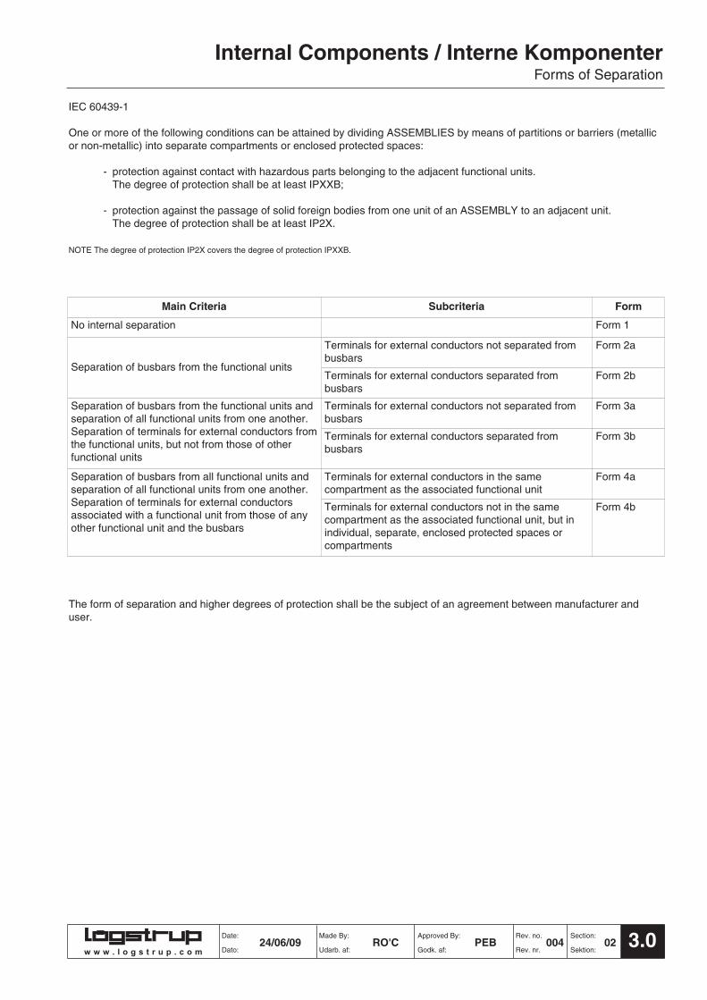
IEC 60439-1
One or more of the following conditions can be attained by dividing ASSEMBLIES by means of partitions or barriers (metallicor non-metallic) into separate compartments or enclosed protected spaces:
- protection against contact with hazardous parts belonging to the adjacent functional units. The degree of protection shall be at least IPXXB;
- protection against the passage of solid foreign bodies from one unit of an ASSEMBLY to an adjacent unit. The degree of protection shall be at least IP2X.
NOTE The degree of protection IP2X covers the degree of protection IPXXB.
The form of separation and higher degrees of protection shall be the subject of an agreement between manufacturer anduser.
Main Criteria Subcriteria Form
No internal separation Form 1
Separation of busbars from the functional units
Terminals for external conductors not separated frombusbars
Form 2a
Terminals for external conductors separated frombusbars
Form 2b
Separation of busbars from the functional units andseparation of all functional units from one another.Separation of terminals for external conductors fromthe functional units, but not from those of otherfunctional units
Terminals for external conductors not separated frombusbars
Form 3a
Terminals for external conductors separated frombusbars
Form 3b
Separation of busbars from all functional units andseparation of all functional units from one another.Separation of terminals for external conductorsassociated with a functional unit from those of anyother functional unit and the busbars
Terminals for external conductors in the samecompartment as the associated functional unit
Form 4a
Terminals for external conductors not in the samecompartment as the associated functional unit, but inindividual, separate, enclosed protected spaces orcompartments
Form 4b

w w w . l o g s t r u p . c o m
Internal Components / Interne KomponenterForms of Separation
4.0 Section: Rev. no. Approved By: Made By: Date:
Sektion: Rev. nr. Godk. af: Udarb. af: Dato:02 004 PEB RO'C 24/06/09
IEC 61439-2
Typical arrangements of internal separation by barriers or partitions are described in Table 104 and are classified as forms
The form of separation and higher degrees of protection shall be the subject of an agreement between ASSEMBLYManufacturer and User.
PSC-ASSEMBLIES can be divided to attain one or more of the following conditions between functional units, separatecompartments or enclosed protected spaces:
- protection against contact with hazardous parts. The degree of protection shall be at least IP XXB;
- protection against the passage of solid foreign bodies. The degree of protection shall be at least IP 2X
NOTE The degree of protection IP 2X covers the degree of protection IP XXB.
Separation may be achieved by means of partitions or barriers (metallic or non-metallic), insulation of live parts or the integralhousing of a device e.g. moulded case circuit breaker.
Main Criteria Subcriteria Form
No internal separation Form 1
Separation of busbars from the functional units
Terminals for external conductors not separated frombusbars
Form 2a
Terminals for external conductors separated frombusbars
Form 2b
Separation of busbars from the functional units andseparation of all functional units from one another.Separation of terminals for external conductors fromthe functional units, but not from those of otherfunctional units
Terminals for external conductors not separated frombusbars
Form 3a
Terminals for external conductors separated frombusbars
Form 3b
Separation of busbars from all functional units andseparation of all functional units from one another.Separation of terminals for external conductorsassociated with a functional unit from those of anyother functional unit and the busbars
Terminals for external conductors in the samecompartment as the associated functional unit
Form 4a
Terminals for external conductors not in the samecompartment as the associated functional unit, but inindividual, separate, enclosed protected spaces orcompartments
Form 4b

w w w . l o g s t r u p . c o m
Internal Components / Interne KomponenterForms of Separation
5.0Date: Made By: Approved By: Rev. no. Section:
Dato: Udarb. af: Godk. af: Rev. nr. Sektion:24/06/09 RO'C PEB 004 02
The following are typical forms of separation by partitions:
FORM 1No internal separation.
FORM 2Separation of busbars from the functional units.
FORM 2ATerminals for external conductors not separatedfrom busbars.
FORM 2BTerminals for external conductors separated frombusbars.
Symbols used in IEC 60 439-1 figures from Annexe D and drawings from Log Cad system.Symbols used in IEC 61 439-2 figures from Annexe AA and drawings from Log Cad system.
Logstrup Indication of Form SeparationLogstrup Indication for External Terminal
(Fixed)
(Fixed)
(Fixed)
Busbars, including distribution busbars
Enclosure Internal separation Functional unit
Terminal(s) for external conductors
5.1 Section: Rev. no. Approved By: Made By: Date:
Sektion: Rev. nr. Godk. af: Udarb. af: Dato:02 002 PEB RO'C 24/06/09
w w w . l o g s t r u p . c o m
Internal Components / Interne KomponenterForms of Separation
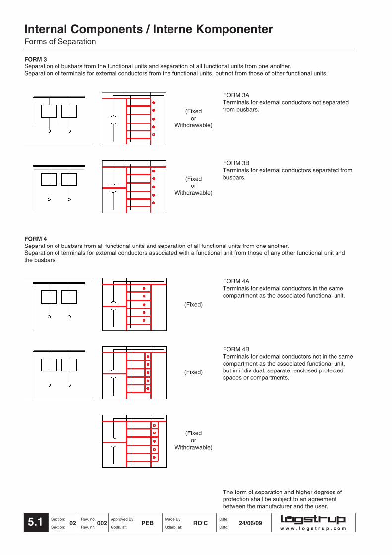
FORM 3ATerminals for external conductors not separatedfrom busbars.
FORM 3BTerminals for external conductors separated frombusbars.
FORM 4Separation of busbars from all functional units and separation of all functional units from one another.Separation of terminals for external conductors associated with a functional unit from those of any other functional unit andthe busbars.
FORM 4BTerminals for external conductors not in the samecompartment as the associated functional unit,but in individual, separate, enclosed protectedspaces or compartments.
The form of separation and higher degrees ofprotection shall be subject to an agreementbetween the manufacturer and the user.
FORM 4ATerminals for external conductors in the samecompartment as the associated functional unit.
(Fixed or
Withdrawable)
(Fixed or
Withdrawable)
(Fixed)
(Fixed)
(Fixedor
Withdrawable)
FORM 3Separation of busbars from the functional units and separation of all functional units from one another. Separation of terminals for external conductors from the functional units, but not from those of other functional units.

w w w . l o g s t r u p . c o m
Internal Components / Interne KomponenterForms of Separation
5.2Date: Made By: Approved By: Rev. no. Section:
Dato: Udarb. af: Godk. af: Rev. nr. Sektion:24/06/09 RO'C PEB 002 02
The UK National annex to BS EN 60439
The Internal separation of assemblies by barriers or partitions is specified in 7.7, and is
subject to agreement between the manufacturer and the user.
The table below gives additional information regarding different types of construction, based
on typical practice in the United Kingdom. Other types of construction are not precluded, and
it is not essential to adopt any of the listed types in order to comply with the requirements of
this British Standard. However, in order to achieve agreement between manufacturers and
users, it is recommended to adopt any of the listed types of construction.
Forms of separation
Main criteria
No separation
Separation of busbars
from the functional
units.
Separation of busbars
from the functional units
and separation of all
functional units from
one another.
Separation of the
terminals for external
conductors from the
functional units, but not
from each other.
Separation of busbars
from the functional units
and separation of all
functional units from
one another, including
the terminals for
external conductors
which are an integral
part of the functional
unit.
Sub-criteria
Terminals for external
conductors not separated from
busbars.
Terminals for external
conductors separated from
busbars.
Terminals for external
conductors not separated from
busbars
Terminals for external
conductors separated from
busbars
Terminals for external
conductors in same
compartment as associated
functional unit.
Terminals for external
conductors not in the same
compartment as the
associated functional unit, but
in individual, separate,
enclosed protected spaces or
compartments
Form
Form 1
Form 2a
Form 2b
Form 3a
Form 3b
Form 4a
Form 4b
Type of construction
Type 1 Busbar separation is achieved by
insulated covering, e.g. sleeving,
wrapping or coatings.
Type 2 Busbar separation is by metallic or non-
metallic rigid barriers or partitions.
Type 1 Busbar separation is achieved by
insulated coverings, e.g. sleeving,
wrapping or coatings.
Type 2 Busbar separation is by metallic or non-
metallic rigid barriers or partitions.
Type 1 Busbar separation is achieved by
insulated coverings, e.g. sleeving,
wrapping or coatings.
Cables may be glanded elsewhere.
Type 2 Busbar separation is by metallic or non-
metallic rigid barriers or partitions.
Cables may be glanded elsewhere.
Type 3 Busbar separation is by metallic or
non-metallic rigid barriers or partitions.
The termination for each functional unit
has its own integral glanding facility.
Type 4 Busbar separation is achieved by
insulated coverings, e.g. sleeving,
wrapping or coatings.
Cables may be glanded elsewhere.
Type 5 Busbar separation is by metallic or
non-metallic rigid barriers or partitions.
Terminals may be separated by
insulated coverings and glanded in
common cabling chamber(s).
Type 6 All separation requirements are by
metallic or non-metallic rigid barriers or
partitions.Cables are glanded in
common cabling chamber(s).
Type 7 All separation requirements are by
metallic or non-metallic rigid barriers or
partitions. The termination for each
functional unit has its own integral
glanding facility.

w w w . l o g s t r u p . c o m
Internal Components / Interne KomponenterForms of Separation
5.3 Section: Rev. no. Approved By: Made By: Date:
Sektion: Rev. nr. Godk. af: Udarb. af: Dato:02 001 PEB RO'C 10/02/03
Form 1No internal separation
Form 2aSeparation of busbars from the functional units.Terminals NOT separated from busbars.
Form 2bSeparation of busbars from the functional units.Terminals separated from busbars.Type 1: Busbar separation by insulated coverings e.g sleeving, wrapping orcoatings.Type 2: Busbar separations by metallic or non metallic rigid barriers orpartitions.
Form 3aSeparation of busbars from the functional units. Separation of functional unitsfrom one another. Separation of terminals from functional units but not from eachother.Terminals NOT separated from busbars
Form 3bSeparation of busbars from the functional units. Separation of functional unitsfrom one another. Separation of terminals from functional units but not from eachother.Terminals separated from busbars.Type 1: Busbar separation by insulated coverings e.g sleeving, wrapping orcoatings.Type 2: Busbar separations by metallic or non metallic rigid barriers orpartitions.
Internal Enclosure Busbar Functional units cableseparation including terminals glands
for external conductors
Form 1
Form 2a
Form 2bTypes 1 & 2
Form 3a
Form 3bTypes 1 & 2
Symbol keys

w w w . l o g s t r u p . c o m
Internal Components / Interne KomponenterForms of Separation
5.4Date: Made By: Approved By: Rev. no. Section:
Dato: Udarb. af: Godk. af: Rev. nr. Sektion:10/02/03 RO'C PEB 001 02
Form 4aSeparation of busbars from the functional units.Separation of functional units from one another.Separation of terminals of functional units Terminals in same compartment as functional unit.
Type 1: Busbar separation by insulated coverings e.g sleeving, wrapping or coatings. Cables glanded elsewhere.
Type 2: Busbar separations by metallic or non metallic rigid barriers or partitions.Cables glanded elsewhere.
Type 3: All separation by metallic or non metallicrigid barriers or partitions.The terminals for each functional unit have their own integral glanding facility.
Form 4bSeparation of busbars from the functional units.Separation of functional units from one another.Separation of terminals of functional units Terminals NOT in same compartment as functional unit.
Type 4: Busbar separation by insulated coverings e.g sleeving, wrapping or coatings. Cables glanded elsewhere.
Type 5: Busbar separations by metallic or non metallic rigid barriers or partitions.Terminals separated by insulated coverings. Cables glanded in common cabling chamber.
Type 6: All separation by metallic or non metallicrigid barriers or partitions. Cables glanded in common cabling chamber.
Type 7: All separation by metallic or non metallicrigid barriers or partitions. The terminals for each functional unit have their own integral glanding facility.
Form 4aTypes1 & 2
Form 4aType 3
Form 4bTypes 4,5 & 6
Form 4bType 7
Symbol keys
Internal Enclosure Busbar Functional units cableseparation including terminals glands
for external conductors

Type X.Y.Z Description Order No. Order No. CodeAluzinc/Aluzink
X.ZMBA 2.2 Base cover / Bundafdækning 26630 AMBA 2.3 Base cover / Bundafdækning 26633 AMBA 2.4 Base cover / Bundafdækning 26633 A
MBA 3.2 Base cover / Bundafdækning 26631 BMBA 3.3 Base cover / Bundafdækning 26634 AMBA 3.4 Base cover / Bundafdækning 26634 A
MBA 4.2 Base cover / Bundafdækning 26632 BMBA 4.3 Base cover / Bundafdækning 26635 AMBA 4.4 Base cover / Bundafdækning 26635 A
MBA 5.3 Base cover / Bundafdækning 26636 AMBA 5.4 Base cover / Bundafdækning 26636 A
XMFC 2 Front plate / Frontplade 26613 AMFC 3 Front plate / Frontplade 26614 AMFC 4 Front plate / Frontplade 26615 AMFC 5 Front plate / Frontplade 26616 A
ZMBP 2 Blank plate / Blindplade 26641 AMBP 3 Blank plate / Blindplade 26535 AMBP 4 Blank plate / Blindplade 26535 AMBP 5 Blank plate / Blindplade 26535 A
Screw / Skrue 96758 AM6 x 12 ISO7380 8.8 FZB
Clip nut / Klipsmøtrik 98077 AM6
Poprivet / Popnitte 99010 A3.2 X 6.7
Internal Components / Interne KomponenterBase Cover, Front Plate and Blank Plates / Bundafdækning, Frontplader og Blindplader
6.0 Section: Rev. no. Approved By: Made By: Date:
Sektion: Rev. nr. Godk. af: Udarb. af: Dato:
Drawing
02 003 PEB RO'C 10/06/09
BASE COVER & FRONT PLATESThe base cover and front plate separatethe busbar section from the cablewaysand the explosion sections. BLANK PLATESThe blank plates may be used to seal offthe busbar section.
BUNDAFDÆKNING & FRONTPLADERBundafdækningen og frontpladerneadskiller skinnesektionen frakabelsektioner og eksplosions - ogventilationssektioner.BLINDPLADERBlindpladerne kan bruges til afskærmningaf skinnesektionen.
➀
➁
➂
➃
➄
➅
➂➀
➁
➄
➃
➅
Delivery code A = 2 weeks B = 6 weeks C = on requestw w w . l o g s t r u p . c o m

Internal Components / Interne KomponenterBottom Cover Plate and End Cover / Bundafdækningsplade og Endeplade
7.0Date: Made By: Approved By: Rev. no. Section:
Dato: Udarb. af: Godk. af: Rev. nr. Sektion:
Type X.Y.Z Description Order No. Order No. Code
X.ZMCO 2.4 Bottom cover plate 27696 B
Bundafdækningsplade
MCO 3.4 Bottom cover plate 27697 ABundafdækningsplade
MCO 4.4 Bottom cover plate 27698 ABundafdækningsplade
MCO 5.4 Bottom cover plate 27700 ABundafdækningsplade
ZMEC 3 End cover / Endeplade 26591 AMEC 4 End cover / Endeplade 26602 A
Screw / Skrue 96756 AM6 x 8 ISO7380 8.8 FZB
Screw / Skrue 96758 AM6 x 12 ISO7380 8.8 FZB
Clip nut / Klipsmøtrik 98077 AM6
Drawing
10/06/09 RO'C PEB 003 02
BOTTOM COVER PLATEThe bottom cover plate separates thehorizontal cableway from the unit section.END COVERThe end cover is fixed to AKA frame barsto separate the explosion section from thecableway.
BUNDAFDÆKNINGSPLADEBundafdækningspladen adskiller denvandrette kabelsektion, i tavlens bund, frakomponentsektionen.ENDEPLADEEndepladen monteres på AKAkantskinner for at adskille eksplosions -og ventilationssektionen frakabelsektionen.
➀
➁
➂
➃
➄
➂
➄➃
➁
➀
Delivery code A = 2 weeks B = 6 weeks C = on requestw w w . l o g s t r u p . c o m

Delivery code A = 2 weeks B = 6 weeks C = on request
Type X.Y.Z Description Order No. Order No. Code
Y.ZEPC 1.1 Side plate / Sideplade 35681 AEPC 2.1 Side plate / Sideplade 35682 A
EPC 1.2 Side plate / Sideplade 35601 AEPC 11/2.2 Side plate / Sideplade 35605 AEPC 2.2 Side plate / Sideplade 35602 AEPC 3.2 Side plate / Sideplade 35603 AEPC 4.2 Side plate / Sideplade 35604 AEPC 5.2 Side plate / Sideplade 35606 A
EPC 1.3 Side plate / Sideplade 35611 AEPC 11/2.3 Side plate / Sideplade 35615 AEPC 2.3 Side plate / Sideplade 35612 AEPC 3.3 Side plate / Sideplade 35613 AEPC 4.3 Side plate / Sideplade 35614 AEPC 5.3 Side plate / Sideplade 35616 A
EPC 1.4 Side plate / Sideplade 35621 AEPC 11/2.4 Side plate / Sideplade 35625 AEPC 2.4 Side plate / Sideplade 35622 AEPC 3.4 Side plate / Sideplade 35623 AEPC 4.4 Side plate / Sideplade 35624 AEPC 5.4 Side plate / Sideplade 35626 A
FLA Grommet / Kabeltylle 90055 A48/26-35
Screw / Skrue 96758 AM6 x 12 ISO7380 8.8 FZB
Screw / Skrue 96756 AM6 x 8 ISO7380 8.8 FZB
Square nut / Firkantmøtrik 98056 AM6 DIN557-5
Internal Components / Interne KomponenterSide Plates / Sideplader
8.0 Section: Rev. no. Approved By: Made By: Date:
Sektion: Rev. nr. Godk. af: Udarb. af: Dato:
Drawing
02 006 PEB RO'C 10/06/09
SIDE PLATESSide plates Type EPC are fixed to thevertical framebars / crossbars separatingthe unit sections from vertical cableways,busbar and explosion sections. Cable exitsare easily made by knocking out embossedholes and fitting grommet type FLAAssembly instructions Pg. 37.0
SIDEPLADERSideplader type EPC monteres på delodrette kantskinner / sprosser og adskillerdermed komponentsektionerne fra delodrette kabelsektioner, skinner,eksplosions - og ventilationssektioner. Detprægede hul åbnes og kabeltylle type FLAisættes.Montagevejledning side 37.0
➀
➁
➂
➃
➄
➃➂
➄
➀
➁
w w w . l o g s t r u p . c o m
Left/Right

SIDE PLATESSide plates Type EPD are fixed to thevertical framebars / crossbars separatingthe unit sections from vertical cableways,busbar and explosion sections. Cable exitsare easily made by knocking out embossedholes and fitting grommet type FLAAssembly instructions Pg. 37.0NB! EPD sideplates can only be usedwith MCB units type EFC (pg. 28.0)
SIDEPLADERSideplader type EPD monteres på delodrette kantskinner / sprosser og adskillerdermed komponentsektionerne fra delodrette kabelsektioner, skinner,eksplosions - og ventilationssektioner. Detprægede hul åbnes og kabeltylle type FLAisættes.Montagevejledning side 37.0NB! EPD sideplader kan kunsammenbygges med MCB indsats typeEFC (side 28.0)
Type X.Y.Z Description Order No. Order No. Code
Y.ZEPD 1.1 Side plate / Sideplade 35572 AEPD 2.1 Side plate / Sideplade 35573 A
EPD 1.2 Side plate / Sideplade 35581 AEPD 2.2 Side plate / Sideplade 35582 AEPD 3.2 Side plate / Sideplade 35583 AEPD 4.2 Side plate / Sideplade 35584 AEPD 5.2 Side plate / Sideplade 35585 A
EPD 1.3 Side plate / Sideplade 35586 AEPD 2.3 Side plate / Sideplade 35587 AEPD 3.3 Side plate / Sideplade 35588 AEPD 4.3 Side plate / Sideplade 35589 AEPD 5.3 Side plate / Sideplade 35590 A
EPD 1.4 Side plate / Sideplade 35591 AEPD 2.4 Side plate / Sideplade 35592 AEPD 3.4 Side plate / Sideplade 35593 AEPD 4.4 Side plate / Sideplade 35594 AEPD 5.4 Side plate / Sideplade 35595 A
FLA Grommet / Kabeltylle 90055 A48/26-35
Screw / Skrue 96758 AM6 x 12 ISO7380 8.8 FZB
Screw / Skrue 96756 AM6 x 8 ISO7380 8.8 FZB
Square nut / Firkantmøtrik 98056 AM6 DIN557-5
Internal Components / Interne KomponenterBase Frames / Basisrammer
8.1Date: Made By: Approved By: Rev. no. Section:
Dato: Udarb. af: Godk. af: Rev. nr. Sektion:
Drawing
10/06/09 RO'C PEB 004 02
Delivery code A = 2 weeks B = 6 weeks C = on requestw w w . l o g s t r u p . c o m
➀
➁
➂
➃
➄
➃➂
➄
➀
➁
Left/Right

Internal Components / Interne KomponenterNotes Page / Notater
8.2 Section: Rev. no. Approved By: Made By: Date:
Sektion: Rev. nr. Godk. af: Udarb. af: Dato:02 001 JLI RO'C 08/12/03
Delivery code A = 2 weeks B = 6 weeks C = on requestw w w . l o g s t r u p . c o m

Delivery code A = 2 weeks B = 6 weeks C = on request
Internal Components / Interne KomponenterVent Plates and Vent Flap / Ventilationssideplader og Klapper
9.0Date: Made By: Approved By: Rev. no. Section:
Dato: Udarb. af: Godk. af: Rev. nr. Sektion:
Type X.Y.Z Description Order No. Order No. Code
Y.ZEUP 1.2 Vent plate / Ventilationssideplade 35631 AEUP 11/2.2 Vent plate / Ventilationssideplade 35636 AEUP 2.2 Vent plate / Ventilationssideplade 35632 AEUP 3.2 Vent plate / Ventilationssideplade 35633 AEUP 4.2 Vent plate / Ventilationssideplade 35634 AEUP 5.2 Vent plate / Ventilationssideplade 35635 B
EUP 1.3 Vent plate / Ventilationssideplade 35641 AEUP 11/2.3 Vent plate / Ventilationssideplade 35646 AEUP 2.3 Vent plate / Ventilationssideplade 35642 AEUP 3.3 Vent plate / Ventilationssideplade 35643 AEUP 4.3 Vent plate / Ventilationssideplade 35644 AEUP 5.3 Vent plate / Ventilationssideplade 35645 A
EUP 1.4 Vent plate / Ventilationssideplade 35651 BEUP 11/2.4 Vent plate / Ventilationssideplade 35656 BEUP 2.4 Vent plate / Ventilationssideplade 35652 BEUP 3.4 Vent plate / Ventilationssideplade 35653 BEUP 4.4 Vent plate / Ventilationssideplade 35654 BEUP 5.4 Vent plate / Ventilationssideplade 35655 B
EUP Vent flap / Ventilationsklap 30891 A
Spring / Fjeder 99001 A4 x 25mm
Screw / Skrue 96758 AM6 x 12 ISO7380 8.8 FZB
Screw / Skrue 96756 AM6 x 8 ISO7380 8.8 FZB
Screw / Skrue 91213 AM4 x 20 DIN912 8.8 FZB
Square nut / Firkantmøtrik 98056 AM6 DIN557
Nut / Møtrik 98099 AM4 DIN985
Drawing
10/06/09 RO'C PEB 006 02
➀
➁
➂
➃
➄
➅
➆
➇
w w w . l o g s t r u p . c o m
VENT PLATES & VENT FLAPVent plates Type EUP and vent flap arefixed to the vertical framebars / crossbars,separating the unit sections from verticalcableways, busbar and explosion sections.In the case of an internal arc fault in a unitsection this provides a means of releasingany overpressure and gases away from theunit and adjacent unit sections.
VENTILATIONSSIDEPLADER OGKLAPPERVentilationssideplader og klapper type EUPmonteres på de lodrette kantskinner /sprosser og adskiller dermedkomponentsektionerne fra de lodrettekabelsektioner, skinner, eksplosions - ogventilationssektioner. I tilfælde af en lysbue ien komponentsektion tillader den overtrykog gasser at slippe ud i eksplosions - ogventilationssektionen.
Left/Right
➀➁➇➂
➅
➄➃
➆

Type X.Y.Z Description Order No. Order No. Code
Y.ZEUD 1.2 Vent plate / Ventilationssideplade 35661 AEUD 2.2 Vent plate / Ventilationssideplade 35662 AEUD 3.2 Vent plate / Ventilationssideplade 35663 AEUD 4.2 Vent plate / Ventilationssideplade 35664 AEUD 5.2 Vent plate / Ventilationssideplade 35665 B
EUD 1.3 Vent plate / Ventilationssideplade 35666 AEUD 2.3 Vent plate / Ventilationssideplade 35667 AEUD 3.3 Vent plate / Ventilationssideplade 35668 AEUD 4.3 Vent plate / Ventilationssideplade 35669 AEUD 5.3 Vent plate / Ventilationssideplade 35670 A
EUD 1.4 Vent plate / Ventilationssideplade 35671 BEUD 2.4 Vent plate / Ventilationssideplade 35672 BEUD 3.4 Vent plate / Ventilationssideplade 35673 BEUD 4.4 Vent plate / Ventilationssideplade 35674 BEUD 5.4 Vent plate / Ventilationssideplade 35675 B
EUD Vent flap / Ventilationsklap 30891 A
Spring / Fjeder 99001 A4 x 25mm
Screw / Skrue 96758 AM6 x 12 ISO7380 8.8 FZB
Screw / Skrue 96756 AM6 x 8 ISO7380 8.8 FZB
Screw / Skrue 91213 AM4 x 20 DIN912 8.8 FZB
Square nut / Firkantmøtrik 98056 AM6 DIN557
Nut / Møtrik 98099 AM4 DIN985
Internal Components / Interne KomponenterVent Plates and Vent Flap / Ventilationssideplader og Klapper
9.1 Section: Rev. no. Approved By: Made By: Date:
Sektion: Rev. nr. Godk. af: Udarb. af: Dato:
Drawing
02 003 PEB RO'C 10/06/09
Delivery code A = 2 weeks B = 6 weeks C = on requestw w w . l o g s t r u p . c o m
Drawing
➀
➁
➂
➃
➄
➅
➆
➇
VENT PLATES & VENT FLAPVent plates Type EUD and vent flap arefixed to the vertical framebars / crossbars,separating the unit sections from verticalcableways, busbar and explosion sections.In the case of an internal arc fault in a unitsection this provides a means of releasingany overpressure and gases away from theunit and adjacent unit sections.NB! EUD vent plates can be used withMCB units type EFC (pg. 28.0)VENTILATIONSSIDEPLADER OGKLAPPERVentilationssideplader og klapper type EUDmonteres på de lodrette kantskinner /sprosser og adskiller dermedkomponentsektionerne fra de lodrettekabelsektioner, skinner, eksplosions - ogventilationssektioner. I tilfælde af en lysbue ien komponentsektion tillader den overtrykog gasser at slippe ud i eksplosions - ogventilationssektionen.NB! EUD ventilationssideplader kan kunsammenbygges med MCB indsats typeEFC (side 28.0)
Left/Right
➀➁➇➂
➅
➄➃
➆

Internal Components / Interne KomponenterNotes Page / Notater
9.2Date: Made By: Approved By: Rev. no. Section:
Dato: Udarb. af: Godk. af: Rev. nr. Sektion:08/12/03 RO'C JLI 001 02
Delivery code A = 2 weeks B = 6 weeks C = on requestw w w . l o g s t r u p . c o m

Delivery code A = 2 weeks B = 6 weeks C = on request
Type X.Y.Z Description Order No. Order No. Code
X.ZMBR 2.2 Rear cover plate / Bagside afdækningsplade 26500 AMBR 2.3 Rear cover plate / Bagside afdækningsplade 26510 AMBR 2.4 Rear cover plate / Bagside afdækningsplade 26573 AMBR 3.2 Rear cover plate / Bagside afdækningsplade 26501 AMBR 3.3 Rear cover plate / Bagside afdækningsplade 26511 AMBR 3.4 Rear cover plate / Bagside afdækningsplade 26574 AMBR 4.2 Rear cover plate / Bagside afdækningsplade 26502 AMBR 4.3 Rear cover plate / Bagside afdækningsplade 26512 AMBR 4.4 Rear cover plate / Bagside afdækningsplade 26575 AMBR 5.3 Rear cover plate / Bagside afdækningsplade 26576 AMBR 5.4 Rear cover plate / Bagside afdækningsplade 26577 A
Wide\BredMBW 3.3 Rear cover plate / Bagside afdækningsplade 26580 AMBW 4.3 Rear cover plate / Bagside afdækningsplade 26581 AMBW 5.3 Rear cover plate / Bagside afdækningsplade 26582 AMBW 3.4 Rear cover plate / Bagside afdækningsplade 26583 AMBW 4.4 Rear cover plate / Bagside afdækningsplade 26584 AMBW 5.4 Rear cover plate / Bagside afdækningsplade 26585 A
MBF 2.2 Front cover plate / Front afdækningsplade 26653 AMBF 2.3/4 Front cover plate / Front afdækningsplade 26656 A
MBF 3.2 Front cover plate / Front afdækningsplade 26654 AMBF 3.3/4 Front cover plate / Front afdækningsplade 26657 A
MBF 4.2 Front cover plate / Front afdækningsplade 26655 BMBF 4.3/4 Front cover plate / Front afdækningsplade 26658 A
MBF 5.3/4 Front cover plate / Front afdækningsplade 26659 A
ZMBR 2 Mounting bracket / Montagebeslag 26503 AMBR 3/4 Mounting bracket / Montagebeslag 26534 A
Screw / Skrue 96757 AM6 x 10 ISO7380 8.8 FZB
Screw / Skrue 96756 AM6 x 8 ISO7380 8.8 FZB
Square nut / Firkantmøtrik 98056 AM6 DIN557-5
Pop rivet / Popnitte 99010 A3.2 x 6.7
Internal Components / Interne KomponenterFront and Rear Cover Plates / Front - og Bagside Afdækningsplader
10.0 Section: Rev. no. Approved By: Made By: Date:
Sektion: Rev. nr. Godk. af: Udarb. af: Dato:
Drawing
02 006 PEB RO'C 10/06/09
FRONT COVER PLATESThe front cover plate type MBF separatesthe unit section from the horizontalcableway .REAR COVER PLATESThe rear cover plate Type MBR & MBWdivides the vertical and horizontal busbarsections, providing fixing positions forbusbar supports.
FRONT AFDÆKNINGSPLADERFront afdækningspladen type MBFadskiller komponentsektionen fra dehorisontale kabelsektion i tavlens top.BAGSIDE AFDÆKNINGSPLADERBagside afdækningspladen type MBR &MBW adskiller den vandrette og lodretteskinnesektion og tjener somunderstøtning for skinnestagene.
➀
➁
➂
➃
➄
➅
➆
➀➁
➆
➃➄➂➅
w w w . l o g s t r u p . c o m

Delivery code A = 2 weeks B = 6 weeks C = on request
Internal Components / Interne KomponenterRear Cover Plate (Release) & Release Cover / Bagside Afdækning (Release) & Release Afdækning
11.0Date: Made By: Approved By: Rev. no. Section:
Dato: Udarb. af: Godk. af: Rev. nr. Sektion:
Type X.Y.Z Description Order No. Order No. Code
X.ZMRR 3.3 Rear cover plate (Release) 26514 B
Bagside afdækningsplade (Release)MRR 3.4 Rear cover plate (Release) 26517 B
Bagside afdækningsplade (Release)
ZMBR 3/4 Mounting bracket / Montagebeslag 26534 A
XMRR 3 Release cover / Release afdækning 26008 B
Screw / Skrue 96756 AM6 x 8 ISO7380 8.8 FZB
Square nut / Firkantmøtrik 98056 AM6 DIN557-5
Pop rivet / Popnitte 99010 A3.2 x 6.7
Plastic rivet / Splitnitte 90412 A
Drawing
10/06/09 RO'C PEB 004 02
REAR COVER PLATES (RELEASE)The rear cover plate (release) divides the verticaland horizontal busbar sections in a drawoutenclosure, providing fixing positions for busbarsupports.RELEASE COVERThe release cover is fixed to the rear cover platetype MRR and insulates the release.NB! These components are only used with thedrawout system.
BAGSIDE AFDÆKNINGSPLADER (RELEASE)Bagside afdækningspladen (release) deler denlodrette og vandrette skinnesektion i draw-out anlægog tjener som understøtning for skinnestagene.RELEASE AFDÆKNINGRelease afdækning monteres påbagsideafdækningspladen som afdækning overreleasen.NB! Disse komponenter bruges kun i draw-outanlæg.
➂➀
➆➅
➃➁➄
➀
➁
➂
➃
➄
➅
➆
w w w . l o g s t r u p . c o m

Type X.Y.Z Description Order No. Order No. Code
X.ZMCR 1.2 Rear cover plate / Bagside afdækningsplade 26519 AMCR 1.3 Rear coverplate / Bagside afdækningsplade 26525 AMCR 1.4 Rear cover plate / Bagside afdækningsplade 26531 A
MCR 2.2 Rear cover plate / Bagside afdækningsplade 26520 AMCR 2.3 Rear cover plate / Bagside afdækningsplade 26526 AMCR 2.4 Rear cover plate / Bagside afdækningsplade 26532 A
MCR 3.2 Rear cover plate / Bagside afdækningsplade 26521 AMCR 3.3 Rear cover plate / Bagside afdækningsplade 26527 AMCR 3.4 Rear cover plate / Bagside afdækningsplade 26533 A
MCF 1.3 Front cover plate/Front afdækningsplade 26528 A
Screw / Skrue 96756 AM6 x 8 ISO7380 8.8 FZB
Square nut / Firkantmøtrik 98056 AM6 DIN557-5
Internal Components / Interne KomponenterRear Cover Plates / Bagside Afdækningsplader
12.0 Section: Rev. no. Approved By: Made By: Date:
Sektion: Rev. nr. Godk. af: Udarb. af: Dato:
Drawing
02 004 PEB RO'C 10/06/09
REAR COVER PLATESThe rear cover plate type MCR separatesthe vertical cableway / explosion sectionfrom the horizontal busbar section.
BAGSIDE AFDÆKNINGSPLADERBagside afdækningspladen type MCRadskiller den lodrette kabelsektion /eksplosions - og ventilationssektion fraden vandrette skinnesektion.
➀
➁
➂
➃
➃
➂
➀➁
Delivery code A = 2 weeks B = 6 weeks C = on requestw w w . l o g s t r u p . c o m

Delivery code A = 2 weeks B = 6 weeks C = on request
Internal Components / Interne KomponenterPartition Plates and Brackets / Skilleplader og Beslag
13.0Date: Made By: Approved By: Rev. no. Section:
Dato: Udarb. af: Godk. af: Rev. nr. Sektion:
Type X.Y.Z Description Order No. Order No. CodeAluminium
X.YMPP 2.2 Partition plate / Skilleplade 25082 AMPP 3.2 Partition plate / Skilleplade 25083 AMPP 4.2 Partition plate / Skilleplade 25084 AMPP 5.2 Partition plate / Skilleplade 25190 A
X Partition Plate Brackets Skillepladebeslag
MPB 2 Top bracket / Top beslag 26687 AMPB 3 Top bracket / Top beslag 26688 AMPB 4 Top bracket / Top beslag 26689 AMPB 5 Top bracket / Top beslag 26710 A
MPB 2 Bottom bracket / Bund beslag 26559 AMPB 3 Bottom bracket / Bund beslag 26560 AMPB 4 Bottom bracket / Bund beslag 26561 AMPB 5 Bottom bracket / Bund beslag 26708 A
Screw / Skrue 96756 AM6 x 8 ISO7380 8.8 FZB
Screw / Skrue 97804 A5.5 x 13 DIN7981C FZB
Square nut / Firkantmøtrik 98056 AM6 DIN557-5
Drawing
10/06/09 RO'C PEB 003 02
PARTITION PLATESThe Aluminium partition plates separatethe horizontal busbar section from thehorizontal cableway.PARTITION PLATE BRACKETSThe partition plate brackets hold the platein position against the BTR rail and frontcover plate.
SKILLEPLADERAluminium skilleplader adskiller denvandrette skinnesektion fra den vandrettekabelsektion.SKILLEPLADEBESLAGSkillepladebeslag fastholder skillepladen tilBTR-skinnen og front afdækningspladen.
➁
➀
➂➅
➄
➃
➀
➁
➂
➃
➄
➅
w w w . l o g s t r u p . c o m

Type X.Y.Z Description Order No. Order No. Code
MJB Joint Bracket•/ Samlebeslag 26661 A(Rear / Bag )
MJB Joint Bracket•/ Samlebeslag 26650 A(Front / Front)
ZMSE 2 Stop end bar / Afslutningstravers 26666 AMSE 3 Stop end bar / Afslutningstravers 26667 AMSE 4 Stop end bar / Afslutningstravers 26668 A
Screw / Skrue 96756 AM6 x 8 ISO7380 8.8 FZB
Screw / Skrue 97804 A5.5 x 13 DIN7981C FZB
Internal Components / Interne KomponenterJoint Brackets & Stop End Bar / Samlebeslag og Afslutningstravers
14.0 Section: Rev. no. Approved By: Made By: Date:
Sektion: Rev. nr. Godk. af: Udarb. af: Dato:
Drawing
02 003 PEB RO'C 10/06/09
JOINT BRACKETSJoint brackets type MJB are used to joinpartition plates type MPP together wheremore that one plate is necessary. STOP END BARSStop end bars type MSE are used ascrossbars providing fixing positions for BSRrails. The stop end bars may also be used assupports for the top cover plates type MBF,MBR, MCF and MCR.
SAMLEBESLAGSamlebeslag type MJB bruges til samling afskilleplader type MPP, når der bruges flere afdisse.AFSLUTNINGSTRAVERSAfslutningstravers type MSE bruges somsprosse, hvor den bruges til fastgørelse afBSR skinner. Afslutningstraverserne kanogså bruges til understøtning af front ogbagside afdækningsplader type MBF, MBR,MCF og MCR.
➀
➁
➂
➃
➄
➀➁
➄
➃
➂
Delivery code A = 2 weeks B = 6 weeks C = on requestw w w . l o g s t r u p . c o m

Delivery code A = 2 weeks B = 6 weeks C = on request
Internal Components / Interne KomponenterExplosion Duct / Eksplosionskanal
15.0Date: Made By: Approved By: Rev. no. Section:
Dato: Udarb. af: Godk. af: Rev. nr. Sektion:
Type X.Y.Z Description Order No. Order No. CodePainted/Malet
ZMVD 2 Vent duct case / Ventilationskanal 26568 BMVD 3/4 Vent duct case / Ventilationskanal 26579 A
MVD 2 Vent duct plate 26567 BPlade for ventilationskana
MVD 3/4 Vent duct plate 26578 APlade for ventilationskanal
MVD 2/3/4 Vent duct bracket 26566 ABeslag for ventilationskanal
MVD 2 Duct flap / Kanalflap 26065 BMVD 3/4 Duct flap / Kanalflap 26076 A
MVD Duct bracket / Kanalbeslag 26569 A
Spring / Fjeder 99001 A4 x 25mm
Pop rivet / popnitte 99010 A3.2 x 6.7
Screw / Skrue 96756 AM6 x 8 ISO7380 8.8 FZB
Screw / Skrue 91213 AM4 x 20 DIN912 8.8 FZB
Rubber bung / Gummispuns 98701 A
Nut / Møtrik 98099 AM4 DIN985
Drawing
10/06/09 RO'C PEB 004 02
EXPLOSION DUCT (MVD)The explosion duct type MVD is fittedover the explosion section. In the event ofan internal arc fault any overpressure andgases are conducted safely to the top ofthe enclosure and released.NB! the duct bracket type MVD is onlyused for 1 module wide explosion /ventilation sections.
EKSPLOSIONSKANAL (MVD)Eksplosionkanalen type MVD monteresover eksplosions / ventilationssektionen. I tilfælde af en lysbuefejl i komponentsektionen bortledes overtryk og gasservia kanalen og ud gennem toppen afkapslingen.NB! Kanalbeslaget type MVD brugeskun i forbindelse med 1 moduleksplosions / ventilationssektioner.
➀
➁
➂
➃
➄
➅
➆
➇
➈
➉
➆➃➂➉➁
➅➈➀➄
➇
11
11MVD
w w w . l o g s t r u p . c o m

Delivery code A = 2 weeks B = 6 weeks C = on request
Type X.Y.Z Description Order No. Order No. CodePainted/Malet
ZMVB 2 Vent duct frame 26548 B
Ramme for ventilationskanalMVB 3/4 Vent duct frame 26556 A
Ramme for ventilationskanal
MVB 3/4 Vent frame / Ventilationsramme 26545 A
MVB 3/4 Vent grill / Ventilationsnet 26539 A
MVD 2 Duct bracket / Kanalbeslag 26547 BMVD 3/4 Duct bracket / Kanalbeslag 26566 A
MVD 2 Duct Flap / Kanalflap 26046 BMVD 3/4 Duct flap / Kanalflap 26076 A
Spring / Fjeder 99001 A4 x 25mm
Pop rivet / popnitte 99010 A3.2 x 6.7
Screw / Skrue 96758 AM6 x 12 ISO7380 8.8 FZB
Screw / Skrue 91213 AM4 x 20 DIN912 8.8 FZB
Rubber bung / Gummispuns 98701 A
Nut / Møtrik 98099 AM4 DIN985Square nut / Firkantmøtrik 98056 AM6 DIN557-5
Internal Components / Interne KomponenterExplosion Flap / Eksplosionsklap
16.0 Section: Rev. no. Approved By: Made By: Date:
Sektion: Rev. nr. Godk. af: Udarb. af: Dato:
Drawing
02 004 PEB RO'C 10/06/09
EXPLOSION FLAP (MVB)The explosion flap type MVB is fitted topanels type APA over the busbar or cablesections. In the event of an internal arcfault the explosion flap releases any overpressure and gases safely through the topof the enclosure.
EKSPLOSIONSKLAP (MVB)Eksplosionsklappen type MVB monterespå plader type APA oversamleskinnesektionerne ogkabelsektionerne. I tilfælde af enlysbuefejl i disse sektioner bortledesovertryk og gasser ud gennem toppen afkapslingen.
➀
➁
➂
➃
➄
➅
➆
➇
➈
➉
12
11
➆
➄
➇➉
➃➀
➅➈➂➁
11
12
w w w . l o g s t r u p . c o m
MVB

Internal Components / Interne KomponenterMain Busbar Cover & Cover Plates / Samleskinneafdækning og Afdækningsplader
17.0Date: Made By: Approved By: Rev. no. Section:
Dato: Udarb. af: Godk. af: Rev. nr. Sektion:
Type X.Y.Z Description Order No. Order No. Code
ZMBC 2 Main busbar cover 26604 A
SamleskinneafdækningMBC 3 Main busbar cover 26606 A
SamleskinneafdækningMBC 4 Main busbar cover 26608 A
Samleskinneafdækning
ZMCP 2 Cover plate / Afdækningsplade 26605 AMCP 3/4 Cover plate / Afdækningsplade 26607 A
MCT End bracket / Endebeslag 27699 A
Pop rivet / Popnitte 99010 A3.2 x 6.7
Drawing
01/05/95 RO'C JLI 001 02
MAIN BUSBAR COVEREnd brackets type MCT and main busbarcovers type MBC seal off the horizontalbusbar sections at both ends of anenclosure.COVER PLATEThe cover plate type MCP seals theexplosion duct when it is used betweentwo unit sections.
SAMLESKINNEAFDÆKNINGEndebeslag type MCT ogskinneafdækning type MBC afskærmerden vandrette skinne i begge ender afkapslingen.AFDÆKNINGSPLADERAfdækningsplade type MCP lukkereksplosionskanalen, når den brugesmellem to komponentsektioner.
➀
➁
➂
➃
➁
➂
➀
➃
Delivery code A = 2 weeks B = 6 weeks C = on requestw w w . l o g s t r u p . c o m

Type X.Y.Z Description Order No. Order No. Code
X.Y Mounting plate / MontagepladeEMK 2.1 x = 306mm y = 189mm 33471 AEMK 2.11/2 x = 306mm y = 284mm 33476 AEMK 2.2 x = 306mm y = 379mm 33472 AEMK 2.3 x = 306mm y = 569mm 33473 AEMK 2.4 x = 306mm y = 759mm 33474 AEMK 2.5 x = 306mm y = 949mm 33475 AEMK 3.1 x = 496mm y = 189mm 33481 AEMK 3.11/2 x = 496mm y = 284mm 33486 AEMK 3.2 x = 496mm y = 379mm 33482 AEMK 3.3 x = 496mm y = 569mm 33483 AEMK 3.4 x = 496mm y = 759mm 33484 AEMK 3.5 x = 496mm y = 949mm 33485 AEMK 4.1 x = 686mm y = 189mm 33491 AEMK 4.11/2 x = 686mm y = 284mm 33496 AEMK 4.2 x = 686mm y = 379mm 33492 AEMK 4.3 x = 686mm y = 569mm 33493 AEMK 4.4 x = 686mm y = 759mm 33494 AEMK 4.5 x = 686mm y = 949mm 33495 AEMK 5.1 x = 876mm y = 189mm 33497 AEMK 5.11/2 x = 876mm y = 284mm 33502 AEMK 5.2 x = 876mm y = 379mm 33498 AEMK 5.3 x = 876mm y = 569mm 33499 AEMK 5.4 x = 876mm y = 759mm 33500 AEMK 5.5 x = 876mm y = 949mm 33501 AEMK 6.2 x = 1066mm y = 379mm 33504 AEMK 6.3 x = 1066mm y = 569mm 33505 A
YEMB 1 Mounting bracket / Montagebeslag 32853 AEMB 11/2 Mounting bracket / Montagebeslag 32961 AEMB 2 Mounting bracket / Montagebeslag 32854 AEMB 3 Mounting bracket / Montagebeslag 32855 AEMB 4 Mounting bracket / Montagebeslag 32856 AEMB 5 Mounting bracket / Montagebeslag 32857 AEMB 6 Mounting bracket / Montagebeslag 32858 AEMB 7 Mounting bracket / Montagebeslag 32859 AEMB 8 Mounting bracket / Montagebeslag 32860 AEMB 9 Mounting bracket / Montagebeslag 32959 AEMB 10 Mounting bracket / Montagebeslag 32960 A
Pop rivet / Popnitte 99010 A3.2 x 6.7Screw / Skrue 96758 AM6 x 12 ISO7380 8.8 FZB Clip nut / Klipsmøtrik 98076 AM6
Internal Components / Interne Komp onenterMounting Plates & Brackets / Montageplader og Beslag
18.0 Section: Rev. no. Approved By: Made By: Date:
Sektion: Rev. nr. Godk. af: Udarb. af: Dato:
Drawing
02 004 PEB RO'C 10/06/09
MOUNTING PLATES & BRACKETSMounting brackets type EMB are fixed toside plates type EPC, EUP. The mountingplates are then fixed to the brackets andcan be easily removed from the front ofthe enclosure.
MONTAGEPLADER OG BESLAGMontagebeslag type EMB fastgøres tilsideplader type EPC, EUP.Montagepladen fastgøres herefter påbeslaget, og kan let afmonteres fratavlens front.
➀
➁
➂
➃
➄
➀
➂
➁
➄
➃
Delivery code A = 2 weeks B = 6 weeks C = on requestw w w . l o g s t r u p . c o m
x
y

Internal Components / Interne KomponenterDividing Plates / Deleplader
19.0Date: Made By: Approved By: Rev. no. Section:
Dato: Udarb. af: Godk. af: Rev. nr. Sektion:
Type X.Y.Z Description Order No. Order No. Code
XEDC 2 Dividing plate / Deleplade 32947 A
z = 431 mmEDC 2 Dividing plate / Deleplade 32948 A
z = 288 mmEDC 2 Dividing plate / Deleplade 32942 A
z = 161 mm
EDC 3 Dividing plate / Deleplade 32952 Az = 431 mm
EDC 3 Dividing plate / Deleplade 32953 Az = 288 mm
EDC 3 Dividing plate / Deleplade 32943 Az = 161 mm
EDC 4 Dividing plate / Deleplade 32957 Az = 431 mm
EDC 4 Dividing plate / Deleplade 32958 Az = 288 mm
EDC 5 Dividing plate / Deleplade 32964 Az = 431 mm
EDC 6 Dividing plate / Deleplade 32965 Az = 431 mm
Screw / Skrue 96758 AM6 x 12 ISO7380 8.8 FZB
Square nut / Firkantmøtrik 98056 AM6 DIN557-5
Drawing
10/06/09 RO'C PEB 005 02
DIVIDING PLATESDividing Plates type EDC are fixed toside plates type EPC and EUP to providehorizontal segregation between individualunit sections.
DELEPLADERDeleplader type EDC fastgøres tilsideplader type EPC og EUP for atadskille funktionsenhederne.
➀
➁
➂
Delivery code A = 2 weeks B = 6 weeks C = on request
z
➁
➀
➂
w w w . l o g s t r u p . c o m

Type X.Y.Z Description Order No. Order No. CodeAluzinc/Aluzink
X.Y Mounting Plate / MontagepladeETM 1.1 x = 118mm, y = 118mm 35913 AETM 1.2 x = 118mm, y = 308mm 35914 AETM 1.3 x = 118mm, y = 498mm 35915 AETM 1.4 x = 118mm, y = 688mm 35916 AETM 1.5 x = 118mm, y = 878mm 35917 AETM 1.6 x = 118mm, y = 1068mm 35918 AETM 1.7 x = 118mm, y = 1258mm 35919 AETM 1.8 x = 118mm, y = 1448mm 35920 AETM 1.9 x = 118mm, y = 1638mm 35921 AETM 1.10 x = 118mm, y = 1828mm 35922 A
X.Y Mounting Plate / MontagepladeETM 2.1 x = 308mm, y = 118mm 35914 AETM 2.2 x = 308mm, y = 308mm 35923 AETM 2.3 x = 308mm, y = 498mm 35924 AETM 2.4 x = 308mm, y = 688mm 35925 AETM 2.5 x = 308mm, y = 878mm 35926 AETM 2.6 x = 308mm, y = 1068mm 35927 AETM 2.7 x = 308mm, y = 1258mm 35928 AETM 2.8 x = 308mm, y = 1448mm 35929 AETM 2.9 x = 308mm, y = 1638mm 35930 AETM 2.10 x = 308mm, y = 1828mm 35931 A
X.Y Mounting Plate / MontagepladeETM 3.1 x = 498mm, y = 118mm 35915 AETM 3.2 x = 498mm, y = 308mm 35924 AETM 3.3 x = 498mm, y = 498mm 35932 AETM 3.4 x = 498mm, y = 688mm 35933 AETM 3.5 x = 498mm, y = 878mm 35934 AETM 3.6 x = 498mm, y = 1068mm 35935 AETM 3.7 x = 498mm, y = 1258mm 35936 AETM 3.8 x = 498mm, y = 1448mm 35937 AETM 3.9 x = 498mm, y = 1638mm 35938 AETM 3.10 x = 498mm, y = 1828mm 35939 A
Internal Components / Interne KomponenterMounting Plates & Brackets / Montageplader og Beslag
20.0 Section: Rev. no. Approved By: Made By: Date:
Sektion: Rev. nr. Godk. af: Udarb. af: Dato:
Drawing
02 002 JLI RO'C 10/02/03
MOUNTING PLATES Mounting plates type ETM are used formounting electrical equipment and can bemounted directly to the frame bars typeAKA and AMA, or to crosshole bars typeEDA.
MONTAGEPLADERMontageplader type ETM bruges sommontageplader for elektriskekomponenter og kan monteres direktemellem kantskinner type AKA og sprossertype AMA eller på krydshulsbeslag typeEDA.
➀
y
x
➀
Delivery code A = 2 weeks B = 6 weeks C = on requestw w w . l o g s t r u p . c o m

Internal Components / Interne KomponenterMounting Plates & Brackets / Montageplader og Beslag
21.0Date: Made By: Approved By: Rev. no. Section:
Dato: Udarb. af: Godk. af: Rev. nr. Sektion:
Type X.Y.Z Description Order No. Order No. CodeAluzinc/Aluzink
X.Y Mounting Plate / MontagepladeETM 4.1 x = 688mm, y = 118mm 35916 AETM 4.2 x = 688mm, y = 308mm 35925 AETM 4.3 x = 688mm, y = 498mm 35933 AETM 4.4 x = 688mm, y = 688mm 35940 AETM 4.5 x = 688mm, y = 878mm 35941 AETM 4.6 x = 688mm, y = 1068mm 35942 AETM 4.7 x = 688mm, y = 1258mm 35943 AETM 4.8 x = 688mm, y = 1448mm 35944 AETM 4.9 x = 688mm, y = 1638mm 35945 AETM 4.10 x = 688mm, y = 1828mm 35946 A
ETM 5.5 x = 878mm, y = 878mm 31947 BETM 5.6 x = 878mm, y = 1068mm 31948 BETM 5.7 x = 878mm, y = 1258mm 31949 BETM 5.8 x = 878mm, y = 1448mm 31950 BETM 5.9 x = 878mm, y = 1638mm 31951 BETM 5.10 x = 878mm, y = 1828mm 31952 B
EBM Mounting bracket 33906 AMontagepladebeslag
Screw / Skrue 97804 A5.5 x 13 DIN7981C FZB
Screw / Skrue 91308 AM6 x 12 8.8 FZB
Clip nut / Klipsmøtrik 98076 AM6
Clip nut / Klipsmøtrik 98078 AM8
Screw / Skrue 96760 AM8 x 16 ISO7380 8.8 FZB
Drawing
10/06/09 RO'C PEB 006 02
MOUNTING PLATES Mounting plates type ETM are used formounting electrical equipment and can bemounted directly to the frame bars type AKAand AMA, or to crosshole bars type EDA.MOUNTING BRACKETSMounting brackets type EBM are used toallow for installation and removal from thefront of the mounting plate.
MONTAGEPLADERMontageplader type ETM bruges sommontageplader for elektriske komponenterog kan monteres direkte mellem kantskinnertype AKA og sprosser type AMA ellermellem krydshulsbeslag type EDA.MONTAGEPLADEBESLAGMontagepladebeslag type EBM bruges, hvorman ønsker mulighed for at montere /afmontere montagepladen fra fronten.
➀
➁
➂
➃
➄
➅
➆
y
x
➂
➅
➁➆➀
➄
➃
Delivery code A = 2 weeks B = 6 weeks C = on requestw w w . l o g s t r u p . c o m

Type X.Y.Z Description Order No. Order No. CodeAluzinc/Aluzink
Cross hole bar / KrydshulsbeslagEDA 1 L = 160mm 35961 C/AEDA 2 L = 350mm 35962 C/AEDA 3 L = 540mm 35963 C/AEDA 4 L = 730mm 35964 C/AEDA 5 L = 920mm 35965 C/A
Cross hole bar / KrydshulsbeslagETA 1 L = 140mm 35947 C/AETA 2 L = 330mm 35948 C/AETA 3 L = 520mm 35949 C/AETA 4 L = 710mm 35950 C/A
Screw / Skrue 97804 A5.5 x 13 DIN7981C FZB
Internal Components / Interne KomponenterCross Hole Bars / Krydshulsbeslag
22.0 Section: Rev. no. Approved By: Made By: Date:
Sektion: Rev. nr. Godk. af: Udarb. af: Dato:
Drawing
02 006 CT RO'C 10/09/08
CROSS HOLE BARSCross hole bars provide fixing points atvarying depths for mounting plates typeETM. Cross hole bars type EDA and EZAare fixed between frame bars type AKAand/or cross bars type AMA. Crossholebars ETA are fixed between 2 EDA orEZA bars. The screw 97804 holds thecross hole bars in place.
KRYDSHULSBESLAGKrydshulsbeslag gør det muligt atmontere montageplader type EMT iforskellige dybder. Krydshulsbeslagenetype EDA og EZA monteres mellemkantskinner type AKA og / eller sprossertype AMA. Krydshulsbeslag type ATAmonteres mellem 2 EDA eller EZAbeslag. Skruen 97804 fastlåserkrydshulsbeslaget.
➀
➁
➂
L
L
Delivery code A = 2 weeks B = 6 weeks C = on request
➀
➁
w w w . l o g s t r u p . c o m
➂

Internal Components / Interne KomponenterACB support rail / Bærejern for luftbryder (ACB)
22.1Date: Made By: Approved By: Rev. no. Section:
Dato: Udarb. af: Godk. af: Rev. nr. Sektion:
Type X.Y.Z Description Order No. Order No. CodeAluzinc
XECB 3 C-profile / C-profil 35971 AECB 4 C-profile / C-profil 35972 AECB 5 C-profile / C-profil 35973 AECB 6 C-profile / C-profil 35974 A
ZECB 3 C-profile / C-profil 35975 AECB 4 C-profile / C-profil 35976 AECB 5 C-profile / C-profil 35977 A
EBB Bracket for C-profile 35980 ABeslag for C-profil
EUM Profile nut/ Profilmøtrik 35981 AM8
FHB Bolt / 6-Kt. bolt 93363 AM8 x 20 DIN931-8.8 FZB
FWS Spring Washer / Fjederskive 98406 AM8 DIN6796 FZB
FBH Screw / Skrue 90311 AM6 x 16 8.8. FZB
Drawing
13/02/03 RO'C JLI 001 02
PROFILE RAIL TYPE ECBECB profile rail is used for fixing differenttypes of air circuit breakers. Brackets typeEBB are used for fixing ECB rails in the“Z” depth between frame bars (AKA)and/or crossbars (AMA).ECB rails in the “X” width are mounted ontop of the ECB rails in the “Z” depth.ECB rails can also be used in the “Z”depth for mounting busbar support rails.
PROFILSKINNE TYPE ECBECB profilskinne anvendes til fastgørelseaf forskellige typer af luftbrydere. Beslagtype EBB anvendes til fastgørelse af typeECB “Z” i enten kantskinne type AKAog/eller sprosse type AMA.Type ECB “X” profilskinne monteresovenpå ECB “Z”. ECB “Z” anvendesendvidere til fastgørelse af skinnestag.
➀
➁
➂
➃
➄
➅
➆
Delivery code A = 2 weeks B = 6 weeks C = on request
➅➀➄➁➂
➃
➆
w w w . l o g s t r u p . c o m

22.2 Section: Rev. no. Approved By: Made By: Date:
Sektion: Rev. nr. Godk. af: Udarb. af: Dato:02 001 JLI RO'C 13/02/03
Delivery code A = 2 weeks B = 6 weeks C = on requestw w w . l o g s t r u p . c o m
Internal Components / Interne KomponenterNotes Page / Notater

Internal Components / Interne KomponenterCompartment Boxes / Indbygningsbokse
23.0Date: Made By: Approved By: Rev. no. Section:
Dato: Udarb. af: Godk. af: Rev. nr. Sektion:
Type X.Y.Z Description Order No. Order No. Code
X.Y Compartment box/ Indbygningsbokse
ESO 2.1 Z = 150mm 32601 BESO 2.2 Z = 150mm 32602 BESO 2.3 Z = 150mm 32603 BESO 2.4 Z = 150mm 32604 B
ESO 3.1 Z = 150mm 32611 BESO 3.2 Z = 150mm 32612 BESO 3.3 Z = 150mm 32613 BESO 3.4 Z = 150mm 32614 B
ESO 4.1 Z = 150mm 32621 BESO 4.2 Z = 150mm 32622 BESO 4.3 Z = 150mm 32623 BESO 4.4 Z = 150mm 32624 B
ESO 2.1 Z = 280mm 32565 BESO 2.2 Z = 280mm 32566 BESO 2.3 Z = 280mm 32567 BESO 2.4 Z = 280mm 32568 B
ESO 3.1 Z = 280mm 32569 BESO 3.2 Z = 280mm 32570 BESO 3.3 Z = 280mm 32571 BESO 3.4 Z = 280mm 32572 B
ESO 4.1 Z = 280mm 32573 BESO 4.2 Z = 280mm 32574 BESO 4.3 Z = 280mm 32575 BESO 4.4 Z = 280mm 32576 B
Screw / Skrue 97804 A5.5 x 13 DIN7981C FZB
Pop rivet / Popnitte 99010 A3.2 x 6.7
Drawing
27/02/98 RO'C JLI 003 02
COMPARTMENT BOXESCompartment boxes type ESO are fittedto the vertical framebars / crossbarsproviding a complete enclosedcompartment.Assembly Instructions Pg. 38.0
INDBYGNINGSBOKSEIndbygningsbokse type ESO fastgøres tilde vertikale kantskinner / sprosser ogdanner en komplet kapslet enhed.Montagevejledning side 38.0
Delivery code A = 2 weeks B = 6 weeks C = on request
Z
➂
➁
➀
➀
➁
➂
w w w . l o g s t r u p . c o m

w w w . l o g s t r u p . c o m
Type X.Y.Z Description Order No. Order No. Code
EHB 2.4.1 C.T & Breaker Housing 34289 AIndgangs-/transformerfelt
EHB 2.5.1 C.T & Breaker Housing 34289 AIndgangs-/transformerfelt
EHB 2.6.1 C.T & Breaker Housing 34289 AIndgangs-/transformerfelt
EHB 2.3.2 C.T & Breaker Housing 34290 AIndgangs-/transformerfelt
EHB 2.5.2 C.T & Breaker Housing 34290 AIndgangs-/transformerfelt
EHB 2.6.2 C.T & Breaker Housing 34290 AIndgangs-/transformerfelt
Internal Components / Interne KomponenterForm 2 Units / Form 2 Indbygningssæt
23.1 Section: Rev. no. Approved By: Made By: Date:
Sektion: Rev. nr. Godk. af: Udarb. af: Dato:
Drawing
02 002 JLI RO'C 09/09/04
Delivery code A = 2 weeks B = 6 weeks C = on request
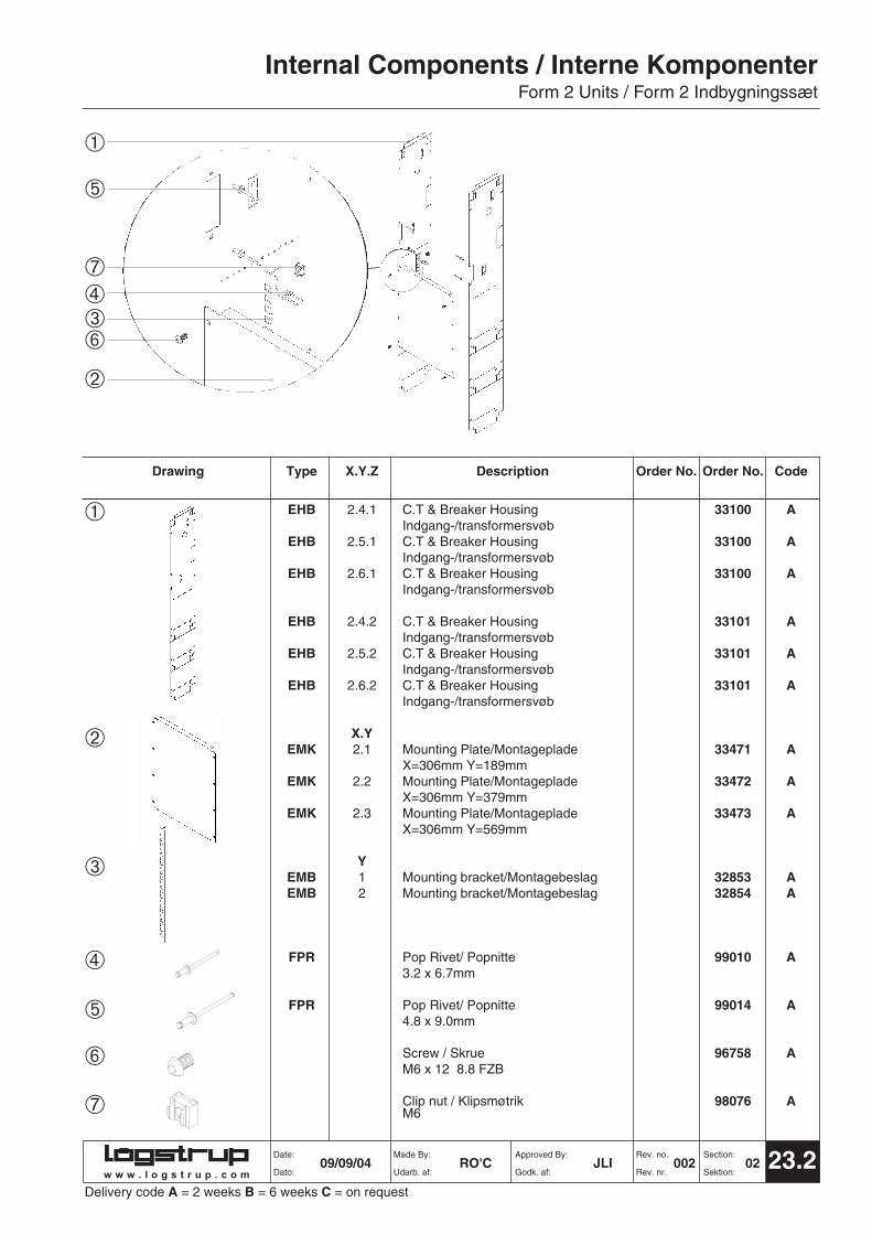
INCOMING UNITThe unit is a complete housing for the mainbreaker and CT's (current transformers)The unit includes the Breaker Housing,Mounting plate type EMK and all thefasteners for the breaker and for fixing thehousing to the frame
INDGANGS-/TRANSFORMERFELTLukket indsats for montage afindgangsbryder og strømtransformer.Leveres inklusiv montageplade type EMKog montage materiel for selve afbryderensamt montage i tavlestativ.
Internal Components / Interne KomponenterForm 2 Units / Form 2 Indbygningssæt
23.2Date: Made By: Approved By: Rev. no. Section:
Dato: Udarb. af: Godk. af: Rev. nr. Sektion:
Type X.Y.Z Description Order No. Order No. Code
EHB 2.4.1 C.T & Breaker Housing 33100 AIndgang-/transformersvøb
EHB 2.5.1 C.T & Breaker Housing 33100 AIndgang-/transformersvøb
EHB 2.6.1 C.T & Breaker Housing 33100 AIndgang-/transformersvøb
EHB 2.4.2 C.T & Breaker Housing 33101 AIndgang-/transformersvøb
EHB 2.5.2 C.T & Breaker Housing 33101 AIndgang-/transformersvøb
EHB 2.6.2 C.T & Breaker Housing 33101 AIndgang-/transformersvøb
X.YEMK 2.1 Mounting Plate/Montageplade 33471 A
X=306mm Y=189mmEMK 2.2 Mounting Plate/Montageplade 33472 A
X=306mm Y=379mmEMK 2.3 Mounting Plate/Montageplade 33473 A
X=306mm Y=569mm
YEMB 1 Mounting bracket/Montagebeslag 32853 AEMB 2 Mounting bracket/Montagebeslag 32854 A
FPR Pop Rivet/ Popnitte 99010 A3.2 x 6.7mm
FPR Pop Rivet/ Popnitte 99014 A4.8 x 9.0mm
Screw / Skrue 96758 AM6 x 12 8.8 FZB
Clip nut / Klipsmøtrik 98076 AM6
Drawing
09/09/04 RO'C JLI 002 02
Delivery code A = 2 weeks B = 6 weeks C = on requestw w w . l o g s t r u p . c o m
➀
➄
➆➃➂➅
➁
➀
➁
➂
➃
➄
➅
➆
➀
➁
➂
➃
➄
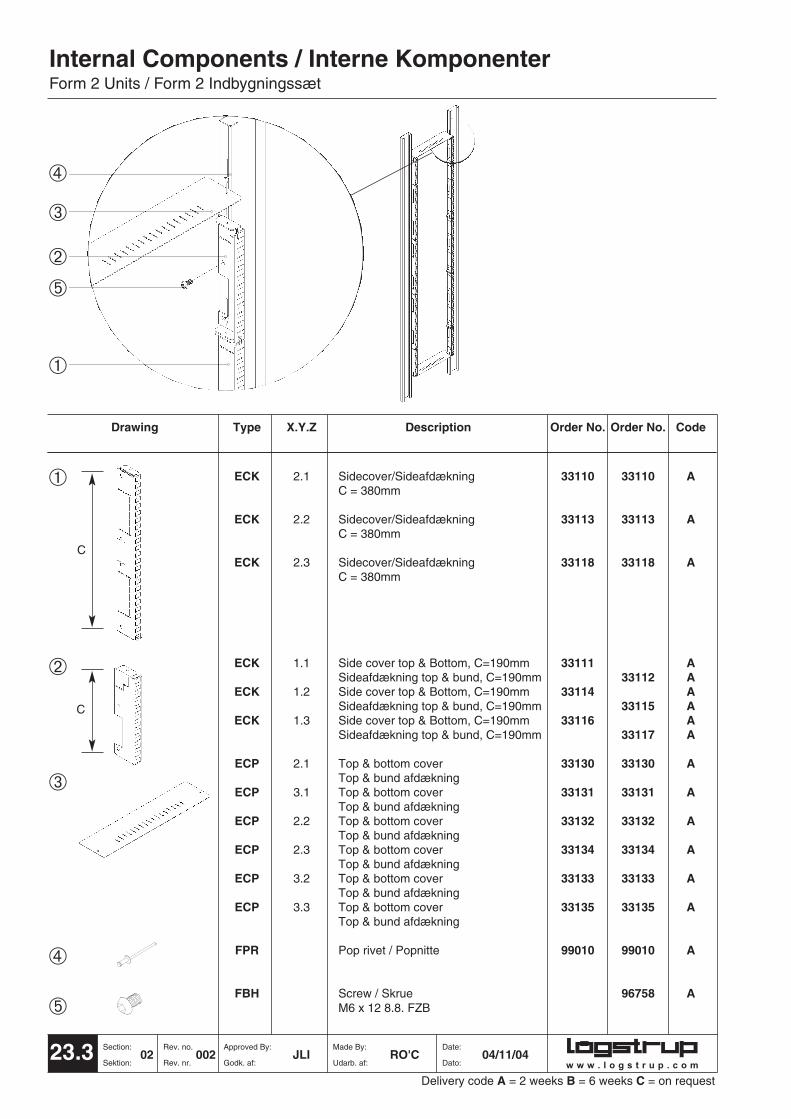
Type X.Y.Z Description Order No. Order No. Code
ECK 2.1 Sidecover/Sideafdækning 33110 33110 AC = 380mm
ECK 2.2 Sidecover/Sideafdækning 33113 33113 AC = 380mm
ECK 2.3 Sidecover/Sideafdækning 33118 33118 AC = 380mm
ECK 1.1 Side cover top & Bottom, C=190mm 33111 ASideafdækning top & bund, C=190mm 33112 A
ECK 1.2 Side cover top & Bottom, C=190mm 33114 ASideafdækning top & bund, C=190mm 33115 A
ECK 1.3 Side cover top & Bottom, C=190mm 33116 ASideafdækning top & bund, C=190mm 33117 A
ECP 2.1 Top & bottom cover 33130 33130 ATop & bund afdækning
ECP 3.1 Top & bottom cover 33131 33131 ATop & bund afdækning
ECP 2.2 Top & bottom cover 33132 33132 ATop & bund afdækning
ECP 2.3 Top & bottom cover 33134 33134 ATop & bund afdækning
ECP 3.2 Top & bottom cover 33133 33133 ATop & bund afdækning
ECP 3.3 Top & bottom cover 33135 33135 ATop & bund afdækning
FPR Pop rivet / Popnitte 99010 99010 A
FBH Screw / Skrue 96758 AM6 x 12 8.8. FZB
Internal Components / Interne KomponenterForm 2 Units / Form 2 Indbygningssæt
23.3 Section: Rev. no. Approved By: Made By: Date:
Sektion: Rev. nr. Godk. af: Udarb. af: Dato:
Drawing
02 002 JLI RO'C 04/11/04
Delivery code A = 2 weeks B = 6 weeks C = on requestw w w . l o g s t r u p . c o m
➃
➂
➁
➄
➀
C
C

Internal Components / Interne KomponenterForm 2 Units / Form 2 Indbygningssæt
23.4Date: Made By: Approved By: Rev. no. Section:
Dato: Udarb. af: Godk. af: Rev. nr. Sektion:
Type X.Y.Z Description Order No. Order No. CodeLeft Right
BHI 2 Holder for busbar support 33161 ABærejern f. Skinneholder
BHI 3 Holder for busbar support 33160 ABærejern f. Skinneholder
BHC Busbar support rear C225 33181 ASkinneholder bag C225
BHC Busbar support front C225 33182 ASkinneholder front C225
FST Screw / Pl.skrue u. spids 97804 A5.5 x 13 DIN7981C FZG
Drawing
12/02/03 RO'C JLI 001 02
Delivery code A = 2 weeks B = 6 weeks C = on requestw w w . l o g s t r u p . c o m
➀➃
➁
➂
➀
➁
➂
➃

➀
➁
Type X.Y.Z Description Order No. Order No. Code
BCK 4 Copper bar / Kobber Skinne C255 13231 A563mm
BCK 6 Copper bar / Kobber Skinne C255 13232 A941mm
BCK 8 Copper bar / Kobber Skinne C255 13233 A1319mm
BCK 10 Copper bar / Kobber Skinne C255 13234 A1697mm
BCK 12 Copper bar / Kobber Skinne C255 13235 A2075mm
BHC Busbar support frontC225 33182 ASkinneholder front C225
Internal Components / Interne KomponenterForm 2 Units / Form 2 Indbygningssæt
23.5 Section: Rev. no. Approved By: Made By: Date:
Sektion: Rev. nr. Godk. af: Udarb. af: Dato:
Drawing
02 001 JLI RO'C 12/02/03
Delivery code A = 2 weeks B = 6 weeks C = on requestw w w . l o g s t r u p . c o m
➀
➁

Internal Components / Interne KomponenterForm 2 Units / Form 2 Indbygningssæt
23.6Date: Made By: Approved By: Rev. no. Section:
Dato: Udarb. af: Godk. af: Rev. nr. Sektion:
Type X.Y.Z Description Order No. Order No. Code
X.Y Transformerindsats (lang)C.T Unit (Long)
BTC 2.2 600A B = 304mm (cu =5 x40mm) 10730
BTC 2.2 1000A B = 304mm (cu =2 x5 x40mm) 2 x 10730
Drawing
09/09/04 RO'C JLI 002 02
C.T UNITThis is a complete package of allcomponents needed to connect the C.Tunit to the panel. It allows CT's to beremoved easily. The C.T unit is availablefor 600A and 1000A , and with a C.T railof 304mm long (3 Transformers). C.T units include Busbar Supports, C.Trails, all Copper Bows, Copper Splicesand all fasteners needed for assemblyand fixing to the C.T housing.
TRANSFORMERINDSATSKomplet indsats for montage afstrømtransformer. Indsatsen kan leveresenten med korte transformerlasker ellerlange transformer lasker (for op til 3stømtransformere). Indsatsen inkludererbefæstigelsesmateriel for montage iindgangs-/transformerfelt.
Delivery code A = 2 weeks B = 6 weeks C = on requestw w w . l o g s t r u p . c o m
L1 L2 L3 N
B

Type X.Y.Z Description Order No. Order No. Code630 A 1000 A
BMB 2 12mm Skinnestag / Busbar Support 10702 10702 A
Busbar Top / Strømskinne, topBBD C = 110mm N 10708 10704 ABBD C = 164mm L3 10709 10705 ABBD C = 218mm L2 10710 10706 ABBD C = 272mm L1 10711 10707 ABTC C = 305mm L1, L2, L3, N 33170 A
(225 A)
BCT C.T Fish Plate / Tranformerlaske 10035 10035 A(lang) / (Long) (1pcs) (2pcs)C = 304mm
BSP Copper Splice / Strømskinne 10714 10712 A146mm(For long C.T Plt.)/(f.lang laske)
Locking Iron / M12 Låseblik 98039 9803940 x36mm
Bolt / 6-Kt. boltM6 x30, M6 x 30 DIN931-8.8 FZG 93316 93316
M12 x45, DIN931-8.8 FZG 93469 93469
M12 x40, DIN931-8.8 FZG 93468 93468
Spring Washer / Fjederskive 98406 98406M6 DIN6796 FZG
Spring Washer / Fjederskive 98412 98412M12 DIN6796 FZG
Square Nut / Firkantmøtrik 98056 98056M6 DIN557
Internal Components / Interne KomponenterForm 2 Units / Form 2 Indbygningssæt
23.7 Section: Rev. no. Approved By: Made By: Date:
Sektion: Rev. nr. Godk. af: Udarb. af: Dato:
Drawing
02 002 JLI RO'C 09/09/04
Delivery code A = 2 weeks B = 6 weeks C = on request
C
C
11
➂
➆➆
➉
➆
➅ ➀ ➄ ➁272mm➁218mm ➁164mm ➁110mm
➉➆ ➈ ➇A
L1 L2 L3 N
11
11
w w w . l o g s t r u p . c o m
A
➆
➄
➀➈➅➃
➀
➁
➂
➃
➄
➅
➆➇
➈
➉

23.8Date: Made By: Approved By: Rev. no. Section:
Dato: Udarb. af: Godk. af: Rev. nr. Sektion:
Type X.Y.Z Description Order No. Order No. Code600A 1000A
BIK * Busbar insulation (3x17mm) 362mm 33171 ASkinneisolation (3x17mm) 362mm
BIK * Busbar insulation (3x17mm) 552mm 33172 ASkinneisolation (3x17mm) 55mm
BIK * Busbar insulation (3x17mm) 742mm 33173 ASkinneisolation (3x17mm) 742mm
BIK * Busbar insulation (3x17mm) 932mm 33174 ASkinneisolation (3x17mm) 932mm
BIK * Busbar insulation (3x17mm) 1122mm 33175 ASkinneisolation (3x17mm) 1122mm
BIK ** Busbar insulation (3x17mm) 336mm 33176 ASkinneisolation (3x17mm) 336mm
BIK ** Busbar insulation (3x17mm) 370mm 33178 ASkinneisolation (3x17mm) 370mm
Drawing
12/02/03 RO'C JLI 001 02
Delivery code A = 2 weeks B = 6 weeks C = on request
Internal Components / Interne KomponenterForm 2 Units / Form 2 Indbygningssæt
w w w . l o g s t r u p . c o m
(*) Insulation for crossing busbar (3 x 17mm)Vertical/vertical busbar
Skinneisolation for skinnekryds (3 x17mm)Vertikal/vertikal skinne
(**) Insulation for crossing busbar (3 x 17mm)CT unit/vertical busbar
Skinneisolation for skinnekryds (3 x17mm)Trafofelt/vertical skinneendvidere til
fastgørelse af skinnestag.
Type X.Y.Z Description Order No. Order No. Code
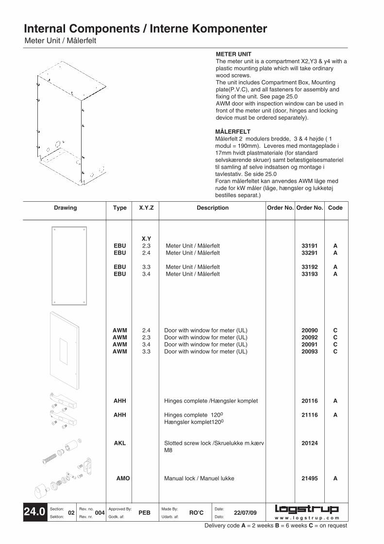
X.YEBU 2.3 Meter Unit / Målerfelt 33191 AEBU 2.4 Meter Unit / Målerfelt 33291 A
EBU 3.3 Meter Unit / Målerfelt 33192 AEBU 3.4 Meter Unit / Målerfelt 33193 A
AWM 2.4 Door with window for meter (UL) 20090 CAWM 2.3 Door with window for meter (UL) 20092 CAWM 3.4 Door with window for meter (UL) 20091 CAWM 3.3 Door with window for meter (UL) 20093 C
AHH Hinges complete /Hængsler komplet 20116 A
AHH Hinges complete 1200 21116 AHængsler komplet1200
AKL Slotted screw lock /Skruelukke m.kærv 20124M8
AMO Manual lock / Manuel lukke 21495 A
Internal Components / Interne KomponenterMeter Unit / Målerfelt
24.0 Section: Rev. no. Approved By: Made By: Date:
Sektion: Rev. nr. Godk. af: Udarb. af: Dato:
Drawing
02 004 PEB RO'C 22/07/09
METER UNITThe meter unit is a compartment X2,Y3 & y4 with aplastic mounting plate which will take ordinarywood screws. The unit includes Compartment Box, Mountingplate(P.V.C), and all fasteners for assembly andfixing of the unit. See page 25.0AWM door with inspection window can be used infront of the meter unit (door, hinges and lockingdevice must be ordered separately).
MÅLERFELTMålerfelt 2 modulers bredde, 3 & 4 højde ( 1modul = 190mm). Leveres med montageplade i17mm hvidt plastmateriale (for standardselvskærende skruer) samt befæstigelsesmaterieltil samling af selve indsatsen og montage itavlestativ. Se side 25.0Foran målerfeltet kan anvendes AWM låge medrude for kW måler (låge, hængsler og lukketøjbestilles separat.)
Delivery code A = 2 weeks B = 6 weeks C = on requestw w w . l o g s t r u p . c o m

Internal Components / Interne KomponenterMeter Unit / Målerfelt
25.0Date: Made By: Approved By: Rev. no. Section:
Dato: Udarb. af: Godk. af: Rev. nr. Sektion:
Type X.Y.Z Description Order No. Order No. Code
X.YEBU 2.3 Meter unit Box / Målerkasse 33208 AEBU 2.4 Meter unit Box / Målerkasse 33217 A
EBU 3.3 Meter unit Box / Målerkasse 33205 AEBU 3.4 Meter unit Box / Målerkasse 33206 A
X.YEEM 2.3 Plastic Mounting Plate / Montageplade 33209 A
White / Hvid 17mmEEM 2.4 Plastic Mounting Plate / Montageplade 33218 A
White / Hvid 17mm
EEM 3.3 Plastic Mounting Plate / Montageplade 33204 AWhite / Hvid 17mm
EEM 3.4 Plastic Mounting Plate / Montageplade 33207 AWhite / Hvid 17mm
Screw / Pl. skrue u.spids 97804 A5.5 x 13 DIN7981C FZG
Poprivet / Popnitte 99010 A3.2 x 6.7mm
Screw/ Skrue 90315 AM6 x 25 DIN912
Clip nut / Klipsmotrik 98077 AM6
Drawing
04/11/04 RO'C JLI 003 02
➀
➁
➂
➃
➄
➅
Delivery code A = 2 weeks B = 6 weeks C = on requestw w w . l o g s t r u p . c o m
➄
➁
➅
➀
➃
➂

w w w . l o g s t r u p . c o m
Internal Components / Interne KomponenterNotes Page / Notater
26.0 Section: Rev. no. Approved By: Made By: Date:
Sektion: Rev. nr. Godk. af: Udarb. af: Dato:02 003 PEB RO'C 12/06/09
Delivery code A = 2 weeks B = 6 weeks C = on request

w w w . l o g s t r u p . c o m
Internal Components / Interne KomponenterNotes Page / Notater
27.0Date: Made By: Approved By: Rev. no. Section:
Dato: Udarb. af: Godk. af: Rev. nr. Sektion:12/06/09 RO'C PEB 002 02
Delivery code A = 2 weeks B = 6 weeks C = on request

Type X.Y.Z Description Order No. Order No. Code
X,Y MCB Units / Indsats EFC 2.1 1 Row /Stribe 34300 A
Blind pcs/BlindstykkeEFC 2.1 1 Row /Stribe 34311 A
Multiple depth/var. skinnedybde
EFC 2.2 2 Row /Stribe 34301 ABlind pcs/Blindstykke
EFC 2.2 2 Row /Stribe 34312 AMultiple depth/var. skinnedybde
EFC 2.3 4 Row /Stribe 34302 A
EFC 2.4 5 Row /Stribe 34303 ABlind pcs/Blindstykke
EFC 2.5 7 Row /Stribe 34304 A
Internal Components / Interne KomponenterM.C.B Units / Indsats for gruppematerie
28.0 Section: Rev. no. Approved By: Made By: Date:
Sektion: Rev. nr. Godk. af: Udarb. af: Dato:
Drawing
02 003 JLI RO'C 09/09/04
M.C.B UNITSThese are a 2 module wide unit for fittingand covering MCB's (Mini CircuitBreakers). Each unit includes SidePlates, DIN rails, Plastic•Cover Platesand all fasteners for assembly and fixingunit to the frame work. A 2 Module wide unit is 289mm wideallowing 16 single pole MCB's (18mm)to be fitted per row.
INDSATS FOR GRUPPEMATERIELKomplet indsats i 2 modulers bredde incl.sidestykke DIN-skinner, plaststøbteafdakningsplader samtbefæstigelsesmateriel til montage itavlestativ.Indsatsen har en lysningsbredde på 289mm (giver plads til 16 enheder á 18mm).
Delivery code A = 2 weeks B = 6 weeks C = on requestw w w . l o g s t r u p . c o m

Internal Components / Interne KomponenterM.C.B Units / Indsats for gruppematerie
29.0Date: Made By: Approved By: Rev. no. Section:
Dato: Udarb. af: Godk. af: Rev. nr. Sektion:
Type X.Y.Z Description Order No. Order No. Code
Y Side Plates / Sidestykke EPT 1 For 1 Row / Stribe 34212 A
EPT 2 For 2 Row / Stribe 34213 A
EPT 3 For 4 Row / Stribe 34214 A
EPT 4 For 5 Row / Stribes 34215 A
EPT 5 For 7 Row / Stribe 34216 A
EPT 1 For 1 Row / Stribe 34217 AMultiple depth/var. skinnedybde
X,YETB 2.1 Top/Bottom Plate / Top-/Bundplade 33002 A
Only EFC Y2 & 4 / Kún EFC Y2 & 4
XEFC 2 Front Plate / Frontplade 33292 A
ERD 2 DIN•Rail / DIN-skinne 32998 ADIN46277 x 300mm
Screw / Pl.skrue u. spids 97804 A5.5 x 13 DIN7981 C FZG
Screw / Skrue 96310 AM6 x 16 Taptite UH-POZ
Drawing
09/09/04 RO'C JLI 003 02
➀
➁
➂
➃
➄
➅
Delivery code A = 2 weeks B = 6 weeks C = on requestw w w . l o g s t r u p . c o m
➁
➄➅➃
➂
➀

Type X.Y.Z Description Order No. Order No. Code
X,Y MCB Units / Indsats EFC 3.1 1 Row /Stribe 34305 A
Blind pcs/BlindstykkeEFC 3.1 1 Row /Stribe 34313 A
Multiple depth/var. skinnedybde
EFC 3.2 2 Row /Stribe 34306 ABlind pcs/Blindstykke
EFC 3.2 2 Row /Stribe 34314 AMultiple depth/var. skinnedybde
EFC 3.3 4 Row /Stribe 34307 A
EFC 3.4 5 Row /Stribe 34308 ABlind pcs/Blindstykke
EFC 3.5 7 Row /Stribe 34309 A
Internal Components / Interne KomponenterM.C.B Units / Indsats for gruppematerie
30.0 Section: Rev. no. Approved By: Made By: Date:
Sektion: Rev. nr. Godk. af: Udarb. af: Dato:
Drawing
02 004 RTJ RO'C 15/09/08
M.C.B UNITSThese are a 3 module wide unit for fittingand covering MCB's (Mini CircuitBreakers). Each unit includes SidePlates, DIN rails, Plastic Cover Plates and all fasteners for assembly and fixingunit to the frame work. A 3 Module wide unit is 469mm wideallowing 26 single pole MCB's (18mm) tobe fitted per row.
INDSATS FOR GRUPPEMATERIELKomplet indsats i 3 modulers bredde incl.sidestykke DIN-skinner,afdækningsplader, plaststøbteafdakningsplader samtbefæstigelsesmateriel til montage itavlestativ.Indsatsen har en lysningsbredde på469mm (Giver plads til 26 enheder á18mm).
Delivery code A = 2 weeks B = 6 weeks C = on requestw w w . l o g s t r u p . c o m

➀
➁
➂
➃
➄
➅
Internal Components / Interne KomponenterM.C.B Units / Indsats for gruppematerie
31.0Date: Made By: Approved By: Rev. no. Section:
Dato: Udarb. af: Godk. af: Rev. nr. Sektion:
Type X.Y.Z Description Order No. Order No. Code
Y Side Plates / Sidestykke EPT 1 For 1 Row / Stribe 34212 A
EPT 2 For 2 Row / Stribe 34213 A
EPT 3 For 4 Row / Stribe 34214 A
EPT 4 For 5 Row / Stribes 34215 A
EPT 5 For 7 Row / Stribe 34216 A
EPT 1 For 1 Row / Stribe 34217 AMultiple depth/var. skinnedybde
X,YETB 3.1 Top/Bottom Plate / Top-/Bundplade 33003 A
Only EFC Y2 & 4 / Kún EFC Y2 & 4
XEFC 3 Front Plate / Frontplade 33293 A
ERD 3 DIN•Rail / DIN-skinne 32999 ADIN46277 x 490mm
Screw / Pl.skrue u. spids 97804 A5.5 x 13 DIN7981C FZG
Screw / Skrue 96310 AM6 x 16 Taptite UH-POZ
Drawing
09/09/04 RO'C JLI 003 02
Delivery code A = 2 weeks B = 6 weeks C = on requestw w w . l o g s t r u p . c o m
➁
➄➅
➃
➂
➀

Internal Components / Interne KomponenterBending Tools / Bukkeværktøj
w w w . l o g s t r u p . c o m
BENDING TOOLSThe bending tool type WBE is used forbending perforated components. It issuitable for both 1mm and 2mm metal.
BUKKEVÆRKTØJBukkeværktøjet type WBE bruges til atbukke de perforede komponenter. Detkan bruges både til 1mm og 2mmgodstykkelse.
➀
Type X.Y.Z Description Order No. Order No. Code
WBE 2 Bending tool / Bukkeværktøj 80072 BWBE 3 Bending tool / Bukkeværktøj 80067 B
32.0 Section: Rev. no. Approved By: Made By: Date:
Sektion: Rev. nr. Godk. af: Udarb. af: Dato:
Drawing
02 001 JLI RO'C 01/05/95
➀
Delivery code A = 2 weeks B = 4 weeks C = on request

Internal Components / Interne KomponenterAssembly Instructions / Montageanvisning
33.0Date: Made By: Approved By: Rev. no. Section:
Dato: Udarb. af: Godk. af: Rev. nr. Sektion:01/05/95 RO'C JLI 001 02
1
2
43
w w w . l o g s t r u p . c o m
✖
✓
SIDE PLATES1. The shaded areas must be
removed in order to fit side plates type EPC, EUP, EPD, EUD or ECO to the top or bottom module of an enclosure.
2. The shaded areas must be removed to allow cross bars type AMA to be fitted between side plates type EPC, EUP, EPD, EUD or ECO to the framework of an enclosure.
3. Bend the joining flaps at 90° to theside plate with the bending tool type WBE.
4. The side plates type EPC, EUP, EPD, EUD or ECO are then aligned and fixed in position.
SIDEPLADER1. De skraverede arealer skal fjernes
på sideplader type EPC, EUP, EPD, EUD•og ECO, når disse skal monteres i top eller bund af kapslingen.
2. De skraverede arealer skal fjernes, hvor der bruges sprosser type AMA i forbindelse med sideplader type EPC, EUP, EPD, EUD og ECO.
3. Buk samlefligen på sidepladen 90° ved hjælp af bukkeværktøj type WBE.
4. Sidepladerne EPC, EUP, EPD, EUD og ECO tilrettes og fastgøres i den korrekte position.

Internal Components / Interne KomponenterAssembly Instructions / Montageanvisning
34.0 Section: Rev. no. Approved By: Made By: Date:
Sektion: Rev. nr. Godk. af: Udarb. af: Dato:02 001 JLI RO'C 01/05/95
COMPARTMENT BOXES1. The shaded areas must be
removed in order to fit compartment box type ESO to the top or bottom module of an enclosure.
2. The shaded areas must be removed in order to allow crossbars type AMA to be fitted between compartment boxes type ESO and frame bars type AKA.
3. Bend joining flaps to 90° with bending tool type WBE
4. Bend sides of box to 90° to sides with bending tool type WBE
INDBYGNINGSBOXE1. De skraverede områder fjernes for
at tilpasse indbygningsboxe type ESO ved montage i top eller bund.
2. De skraverede områder fjernes hvis der skal bruges sprosser type AMA.
3. Buk samleflapperne 90° med bukkeværktøj type WBE.
4. Buk siderne 90° med bukkeværktøj type WBE.
2
3
4
1
w w w . l o g s t r u p . c o m

Casing Components / KapslingskomponenterAssembly Instructions / Montageanvisning
35.0Date: Made By: Approved By: Rev. no. Section:
Dato: Udarb. af: Godk. af: Rev. nr. Sektion:25/06/96 RO’C SMR 002 02
COMPARTRMENT BOXES
5. Bend both top and bottom flaps of box to 90° to form a box.
6. Pop rivet the top/bottom to the sides with pop rivets Order No. 99010
7. Align and fit compartment box to frame bars type AKA.
INDBYGNINGSBOXE5. Buk top og bund 90° for at danne
indbygningskassen.
6. Popnit top og bund til siderne med popnit ordre no. 99010.
7. Juster og monter indbygningsboxen til kantskinnerne type AKA.
5
6
7
w w w . l o g s t r u p . c o m

Internal Components / Interne KomponenterTerminology & Dimensions / Terminologi & Målsætning
36.0 Section: Rev. no. Approved By: Made By: Date:
Sektion: Rev. nr. Godk. af: Udarb. af: Dato:02 003 PEB RO'C 21/07/09
FUNCTIONAL UNIT SECTIONThe functional unit Section contains theelectrical equipment for both outgoing andincoming units.
w w w . l o g s t r u p . c o m
1010mm 1580mm 1770mm
2425
mm
2425
mm
2425
mm
1010mm 1580mm 1770mm
2425
mm
2425
mm
2425
mm
1010mm 1580mm 1770mm
2425
mm
2425
mm
2425
mm
1010mm 1580mm 1770mm
2425
mm
2425
mm
2425
mm
CABLE SECTIONThe cable section runs vertically beside eachfunctional unit section, and may be of varyingwidths allowing for easy wiring.
DISTRIBUTION & MAIN BUSBAR SECTIONThe Distribution Busbar section runs verticallybehind each functional unit section and theMain Busbar runs horizontally behind thecable section at the top of the panel.
EXPLOSION / VENTILATION SECTIONAn explosion / ventilation section may beincluded in the enclosure as an added safetyprecaution. The explosion / ventilation sectionis accessible by each functional unit. Thisconducts any overpressure and gases thatmay result from an internal arc fault safely tothe top of the enclosure to be released.