intermediate report on methodology - rodin
TRANSCRIPT

Project IST-511599RODIN
“Rigorous Open Development Environment for Complex Systems”
RODIN Deliverable D19
Intermediate report on methodology
Editor: C. B. Jones (Newcastle University)
Public Document
29th August 2006
http://rodin.cs.ncl.ac.uk/
Abstract
One aim of the Rodin project is to contribute formal methods which will underpin thecreation of fault-tolerant systems. This intermediate report from WP2 (Methodology) describesprogress during the second year of the Rodin project; it also discusses our plans for the finaldeliverable on methodology.
Contributors:
Many people have written material for Chapters 3 and 2; specific contributions include:Section 2.1 written by Linas LaibinisSection 2.2 written by Ian JohnsonSection 2.3 written by Ian OliverSection 2.4 written by Neil Evans and Michael Butler (on behalf of Praxis)Section 2.5 written by Maciej KoutnySection 3.1 written by Maciej KoutnySection 3.2 written by A. Iliasov, A. Romanovsky, E. Troubitsyna, L. LaibinisSection 3.3 written by Joey Coleman and Cliff JonesSection 3.4 written by Manoranjan Satpathy, Qaisar A. Malik and Johan LiliusSection 3.5 written by Elena TroubitsynaSection 3.6 written by Michael ButlerSection 3.7 written by Joey Coleman and Cliff JonesSection 3.8 written by Divakar Yadav and Michael ButlerSection 3.9 written by Fernando Castor Filho, Alexander Romanovsky, and Cecılia Mary
F. RubiraSection 3.10 written by Alexei Iliasov, Victor Khomenko, Maciej Koutny, Apostolos Niaouris
and Alexander Romanovsky
2

Contents
1 Introduction 5
2 What we are learning from the tension with the case studies 92.1 Case Study 1: Formal Approaches in Protocol Engineering . . . . . . . . . . . 92.2 Case Study 2: Engine Failure Management System . . . . . . . . . . . . . . . 102.3 Case Study 3: MDA . . . . . . . . . . . . . . . . . . . . . . . . . . . . . . . . 11
2.3.1 Development . . . . . . . . . . . . . . . . . . . . . . . . . . . . . . . 112.3.2 Model Driven ‘XXX’ . . . . . . . . . . . . . . . . . . . . . . . . . . . 122.3.3 MDA in Rodin . . . . . . . . . . . . . . . . . . . . . . . . . . . . . . 12
2.4 Case Study 4 . . . . . . . . . . . . . . . . . . . . . . . . . . . . . . . . . . . 142.4.1 Problems to be Overcome . . . . . . . . . . . . . . . . . . . . . . . . 142.4.2 A Methodology for Specifying CDIS . . . . . . . . . . . . . . . . . . 142.4.3 Refinement . . . . . . . . . . . . . . . . . . . . . . . . . . . . . . . . 19
2.5 Case Study 5: Ambient Campus . . . . . . . . . . . . . . . . . . . . . . . . . 26
3 Discussion of issues 283.1 Towards an Algebra of Abstractions for Communicating Processes . . . . . . . 283.2 Rigorous Development of Fault-Tolerant Agent Systems . . . . . . . . . . . . 30
3.2.1 Fault-tolerance . . . . . . . . . . . . . . . . . . . . . . . . . . . . . . 313.2.2 Interoperability . . . . . . . . . . . . . . . . . . . . . . . . . . . . . . 323.2.3 Conclusion . . . . . . . . . . . . . . . . . . . . . . . . . . . . . . . . 33
3.3 Deriving specifications . . . . . . . . . . . . . . . . . . . . . . . . . . . . . . 333.4 Synthesis of Scenario Based Test Cases from B Models . . . . . . . . . . . . . 34
3.4.1 Terminology . . . . . . . . . . . . . . . . . . . . . . . . . . . . . . . 353.4.2 Existing Approaches . . . . . . . . . . . . . . . . . . . . . . . . . . . 363.4.3 The B Method . . . . . . . . . . . . . . . . . . . . . . . . . . . . . . 373.4.4 The Problem . . . . . . . . . . . . . . . . . . . . . . . . . . . . . . . 373.4.5 Refinement in B . . . . . . . . . . . . . . . . . . . . . . . . . . . . . 373.4.6 The Approach . . . . . . . . . . . . . . . . . . . . . . . . . . . . . . . 393.4.7 An Example . . . . . . . . . . . . . . . . . . . . . . . . . . . . . . . 393.4.8 The Algorithm . . . . . . . . . . . . . . . . . . . . . . . . . . . . . . 393.4.9 Exponential Nature of the Algorithm . . . . . . . . . . . . . . . . . . 423.4.10 Analysis . . . . . . . . . . . . . . . . . . . . . . . . . . . . . . . . . 433.4.11 Conclusion . . . . . . . . . . . . . . . . . . . . . . . . . . . . . . . . 44
3.5 Formal View of Developing a Mechanism for Tolerating Transient Faults . . . . 443.6 Synchronisation-based Decomposition for Event B . . . . . . . . . . . . . . . 47
3

3.6.1 Machines as interactive systems . . . . . . . . . . . . . . . . . . . . . 483.6.2 Refinement and New Events . . . . . . . . . . . . . . . . . . . . . . . 493.6.3 Parallel Composition . . . . . . . . . . . . . . . . . . . . . . . . . . . 513.6.4 CSP Correspondence . . . . . . . . . . . . . . . . . . . . . . . . . . . 543.6.5 Design Technique: Refinement and Decomposition . . . . . . . . . . . 563.6.6 Concluding . . . . . . . . . . . . . . . . . . . . . . . . . . . . . . . . 56
3.7 Justifying the soundness of rely/guarantee reasoning . . . . . . . . . . . . . . 573.8 Development of distributed transactions in Event-B . . . . . . . . . . . . . . . 58
3.8.1 Distributed Transactions . . . . . . . . . . . . . . . . . . . . . . . . . 593.8.2 Transaction Model for Abstract Central Database . . . . . . . . . . . . 593.8.3 Refinement with Replicated Database . . . . . . . . . . . . . . . . . . 603.8.4 Gluing Invariants . . . . . . . . . . . . . . . . . . . . . . . . . . . . . 633.8.5 Conclusions . . . . . . . . . . . . . . . . . . . . . . . . . . . . . . . . 65
3.9 Verification of Coordinated Exception Handling . . . . . . . . . . . . . . . . . 653.10 On Specification and Verification of Location-based Fault Tolerant Mobile Sys-
tems . . . . . . . . . . . . . . . . . . . . . . . . . . . . . . . . . . . . . . . . 683.10.1 Our approach . . . . . . . . . . . . . . . . . . . . . . . . . . . . . . . 693.10.2 Model-checking mobile systems . . . . . . . . . . . . . . . . . . . . . 693.10.3 Key implementation issues . . . . . . . . . . . . . . . . . . . . . . . . 703.10.4 Experimental results . . . . . . . . . . . . . . . . . . . . . . . . . . . 713.10.5 Conclusions . . . . . . . . . . . . . . . . . . . . . . . . . . . . . . . . 73
3.11 Bits ’n Pieces . . . . . . . . . . . . . . . . . . . . . . . . . . . . . . . . . . . 75
4 The way ahead 76
A Possible structure of the final WP2 report 87
4

Chapter 1
Introduction
This chapter indicates progress on technical issues which were identified in D9 (the “Prelim-inary report on Methodology”). Overall, we feel that very good progress is being made onissues of development methods. Chapter 2 sets out methodological insights which have comefrom the case studies (this can of course be read in conjunction with D18). The variety of thecase studies is having the desired effect of stretching our ideas on methods. Chapter 3 –likeD9– provides a series of “essays” on methodological issues. These vary considerably in length— to a large extent this is caused by whether publications exist to which the essay can point fortechnical details.1
Possible plans for the final deliverable on methodology are set out in Chapter 4 (and onestructure for the final document sketched in Appendix A). We should be particularly gratefulfor input at the October 2006 Project Review on the alternatives for the final methodologydocument(s).
Figure 1.1 provides a reminder of the list “issues” identified in D9: they are provided with“I-n” numbers for reference elsewhere in this (D19) report. Comments on progress on theseissues:
I-1 Building a specification from parts We see this as an important issue for “scaling”; it isaddressed under §2.4 below.
I-2 Partial functions This is not seen as a significant issue — we shall return to it duringproof experiments with the new Rodin prover but the current Event B position is certainlyadequate. (A further paper has been produced [Jon06b].)
I-3 Role of invariants This is not seen as a significant issue — we’ll return to it during proofexperiments with the new Rodin prover.
I-4 Controlling the order of operation execution Work is on-going but there have been nosignificant publications on this topic (but see [Jon05b]).
1It is also worth mentioning that Section 2.4 is rather longer than the other case study sections because anumber of technical issues are included in the text.
5

Number D9 Section Brief descriptionI-1 §2.1.1 Building a specification from partsI-2 §2.1.2 Partial functionsI-3 §2.1.3 Role of invariantsI-4 §2.1.4 Controlling the order of operation executionI-5 §2.2.1 Deriving specifications (of “control systems”)I-6 §2.2.2 Domain modellingI-7 §2.3.1 Comping with interferenceI-8 §2.3.2 Refining atomicityI-9 §2.3.3 Process algebras and net theoryI-10 §2.3.4 Process algebra and Event BI-11 §2.4.1 Failure managementI-12 §2.4.2 Determining the failure specification of a systemI-13 §2.4.3 BPEL-like languagesI-14 §2.5.1 Synergy between model checking and reasoningI-15 §2.5.2 Rigorous reasoningI-16 §2.5.3 Role of programming languagesI-17 §3 Requirements structureI-18 §4 Linking UML and BI-19 §5 Records in Event BI-20 §6 Methodology for mobile systemsI-21 §7 Model driven developmentI-22 §8 Exception handling in mobile environments
Figure 1.1: Reference numbers from issues in D19
6

I-5 Deriving specifications (of “control systems”) This has been an active area; an updateis given in §3.3 below.
I-6 Domain modelling There has been relevant activity in several areas — here, see in par-ticular Section 2.3. Before the final report is written, we will position each of the case studieswith respect to domains.
I-7 Coping with interference Addressed under §3.7 below.
I-8 Refining atomicity See §2.3, §3.2, §3.6, §3.8, §3.1, §3.11 below.
I-9 Process algebras and net theory This too is an active area; here, it is touched on under§3.1 below.
I-10 Process algebra and Event B Another active area; it is touched on under §3.1 below.
I-11 Failure management Addressed under §2.2 below.
I-12 Determining the failure specification of a system Addressed under §3.5 below.
I-13 BPEL-like languages No further work is envisaged on this topic.
I-14 Synergy between model checking and reasoning We have thought about and discussedthis area but await experiments with the main Rodin tools and Plugins to draw conclusions(e.g. the encouraging performance results with model checking pi-calculus will certainly affecthow a user will experiment with model-checking before attempting proofs).
I-15 Rigorous reasoning We will be experimenting on this with the new proof tool.
I-16 Role of programming languages Jean-Raymond Abrial talked about this in his VSTTEposition statement. Also addressed under §2.3 below.
I-17 Requirements structure We are using the ideas set out in D9 and will report more infurther deliverables.
I-18 Linking UML and B Addressed under §2.3 below.
I-19 Records in Event B Addressed under §2.4 below.
I-20 Methodology for mobile systems Addressed under §2.5, §3.2, §3.10, §3.11 below.
I-21 Model driven development Addressed under §2.1, §2.3 below.
7
I-22 Exception handling in mobile environments Addressed under §2.1, §2.5, §3.9, §3.2,§3.11 below.
Generic specifications Addressed under §2.4 below.
Testing Addressed under §3.4 below.
Transience Addressed under §3.5 (and indirectly –see references– in§3.3) below.
Special needs of users unfamiliar with formal methods Addressed under §2.1, §2.3 below.
Integration with less formal methods Addressed under §2.3, §3.11 below and in our on-going “UML/B” work.
Link to Rodin Tasks
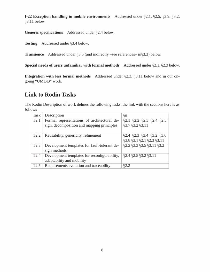
The Rodin Description of work defines the following tasks, the link with the sections here is asfollows
Task Description §nT2.1 Formal representations of architectural de-
sign, decomposition and mapping principles§2.1 §2.2 §2.3 §2.4 §2.5§3.7 §3.2 §3.11
T2.2 Reusability, genericity, refinement §2.4 §2.3 §3.4 §3.2 §3.6§3.8 §3.1 §2.1 §2.3 §3.11
T2.3 Development templates for fault-tolerant de-sign methods
§2.2 §3.3 §3.5 §3.11 §3.2
T2.4 Development templates for reconfigurability,adaptability and mobility
§2.4 §2.5 §3.2 §3.11
T2.5 Requirements evolution and traceability §2.2
8

Chapter 2
What we are learning from the tensionwith the case studies
It was always our intention that the case studies would provide feedback to the evolving devel-opment methods. This is indeed proving to be the case. Here, in this intermediate deliverablefrom WP2, we specifically identify some of the things we are learning.
2.1 Case Study 1: Formal Approaches in Protocol Engineer-ing
The work on Case Study 1 –Formal Approaches in Protocol Engineering– focuses on formal-isation and verification of the design method Lyra. Lyra is an UML2-based service-orientedmethod for development of telecommunication systems and communication protocols. In thefirst year of the RODIN project we have developed formal specification and refinement patternsreflecting essential Lyra models and transformations. This allowed us to verify the Lyra devel-opment steps (phases) on the basis of stepwise refinement of a formal system model in the BMethod. This work has been reported in [LTL+05].
During the second year our work has progressed in two directions. First, the further devel-opment of the specification and refinement patterns to incorporate the fault tolerance mecha-nisms used in the domain [LTL+06]. Second, the development of an approach to formal veri-fication of consistency of the UML2-based Lyra development [LIM+05]. Let us now describethese methodological advances in more detail.
To incorporate formal reasoning about fault tolerance into the formalized Lyra develop-ment flow, the specification and refinement patterns for Lyra models have been extended withexplicit representation of possible errors and error recovery. The extension has affected thespecifications of service components directly responsible for controlling the service execu-tion flow (called service directors). The recovery mechanisms allowing a service director toretry the failed service execution as well as to ”roll back” in the service execution flow havebeen incorporated in the specification pattern of a service director. Moreover, in refinementsteps modelling service decomposition and distribution over a given network, the fault tol-erance mechanisms have been accordingly distributed over the involved service components.Termination of potentially infinite recovery process is guaranteed by modelling the maximalexecution time that is gradually decreased by service execution.
9

To automate translation and verification of Lyra UML models in the B Method, we havedeveloped an approach to verifying the consistency of the provided UML models. The approachconsists of formalisation of the intra-consistency (i.e., expressing the relationships betweenmodels within the same Lyra development phase) and inter-consistency (i.e., the relationshipsbetween different Lyra phases) rules for the Lyra UML models. The formalisation is doneusing the B Method in such a way that the requirements are gradually (i.e., phase by phase)introduced and incorporated by the corresponding B refinement steps. The achieved resultscreate a basis for developing a formally verified UML profile for Lyra.
2.2 Case Study 2: Engine Failure Management System
Rodin methods and technology such as UML-B have shown promise in tackling Failure Man-agement Domain concerns for ATEC such as closing the semantic gap (i.e., closer mappingof the problem domain to the design) and providing a reliable reusable process to meet thedemands of a safety environment.
In the first year the University of Southampton in cooperation with ATEC developed ageneric model of the failure management system (FMS) based on a UML-B profile. The 2ndyear work on the case material consists of methodological contributions by ATEC, Univer-sity of Southampton (Soton) and Aabo Akademi (Aabo). Which have been outlined in theRODIN D18 deliverable.
ATEC have been evaluating emerging RODIN methodology by undertaking a pilot study ofthe case material. Their work has demonstrated the usability of the methodology and its toolsby a novice user of formal methods and B. However, it was felt more guidance in model de-velopment should be developed and this is to be addressed in collaborative research with AaboAkademi and the University of Southampton. ATEC’s exploration of methodology has alsoidentified a need to provide more flexibility in the refinement process in order to identify validrequirements early from which a more rigorous refinement chain can be constructed. A pro-cess to address this issue was investigated which has been called Idealisation-De-idealisation.Idealisation supports the idea that obtaining good abstractions are difficult initially and thatless rigorous development can initially be undertaken to establish the main functionality of amodel. De-idealisation refers to developing the model rigorously to obtain consistency in therefinement chain..
The University of Southampton has continued developing methodology supporting thegeneric model. Work at Southampton has proposed a prototype process for the Verificationand Validation of a generic specification of this type, demonstrating stage (1): validate struc-tural model using test data — and stage (2): verify system instance data against structuralinstance model. This was done using the existing UML-B tool and ProB model checker. Thespecification has been decomposed into features as the first step in an investigation of feature-based description, refinement and composition of generic specifications. This investigation willestablish how to structure such feature-based transformations using the relevant mechanisms ofthe Event-B language: refinement, decomposition and generic instantiation. A student projectgroup at the University of Southampton has developed a plugin for UML-B, the RequirementsManager. This tool is a PostgreSQL-based repository of FM system instance data, with func-tions to input and verify instance data against the generic model, and to upload the data toUML-B for generation of a system instance UML-B specification. As a user-acceptance test of
10

the tool, the Verification and Validation exercise of the previous paragraph has been performedwith a full system instance dataset.
Aabo Akademi has been working with classical refinement development of the FMS (seeSection 3.5). The main result of developing the FMS by stepwise refinement in B is a setof formal templates for specifying and refining the FMS. The developed FMS is able to copewith transient faults occurring in the system with multiple homogeneous analogue sensors. Theformal templates specify sensor recovery after the occurrence of transient faults and ensure thenon-propagation of errors further into the system.
2.3 Case Study 3: MDA
First to note is that overall Nokia is not a general user of ‘formal methods’ as, say, someautomotive or aerospace companies might be. However it is well known that we have a needfor analysis of the designs that we are producing.
Secondly is that we already have well defined (and in some cases ingrained) processes andmethods for the development of the various kinds of embedded and real-time systems that arefound in mobile devices.
It is often the case that the adoption of new development technologies requires a wholesalechange in the way systems are developed. It is then often also the case that the new methodfails because of the burden of trying adapt it and the existing processes to each other.
We take the view that new techniques such as those being developed inside Rodin should beagnostic to the underlying processes and be compatible with existing techniques and methodsas far as possible. This is to minimise the disruption caused when introducing these techniques.
2.3.1 Development
The use of formal methods is already in place, albeit in a minor way due to the plethora ofnotations and in most cases the seeming lack of integration with the defacto languages andprocesses — particularly the UML.
The first year of Rodin concentrated more on the use of B for the specification of the NoTA(Network on Terminal Architecure) system. Here we had the chance to compare the use ofUML+B and plain B with already existing models and an implementation constructed throughthe use of “agile methods” and the SDL language.
The results of the first year show that overall productivity increases and the amount ofdesign errors significantly decreases when using a formal method. The caveat here is that theuse of formal methods must be ‘pragmatic’ rather than ‘dogmatic’ in nature. The first versionsof the upper layers of the NoTA protocol stacks based upon the verified designs are currentlybeing implemented and tested in production environments.
The second year has focussed much more on the superstructure that Rodin must fit intoin order to gain acceptance and be used with our model based methods. Later sections herediscuss what we mean by MDA and MDE in this context.
Work with Abo Akademi has resulted in two threads of development: the first concentratingon patterns expressed through ‘MDA-style transformations’ for adding fault tolerance aspectsto a B specification; and secondly more formal underpinnings for ‘model based’ structures.
11

Further work whcih is due to start during the third year of the project will focus on hardwarespecification language generation from EventB specifications.
Some work has been proposed with University of Southampton on additions to U2B —some of which have been prototyped locally and product line structures.
(The work between ATEC and University of Southampton is being followed closely.)
2.3.2 Model Driven ‘XXX’
The term ‘model driven” is becomming overused such that it can be almost applied as a prefixto any computing term: model, engineering, testing, development etc. However the (modern)origins of the term come from the OMG’s Model Driven Architecture concept which attempts toprovide a framework (Figure 2.1) for relating models of varying levels of abstraction together.The OMG’s MDA also seeks to enforce the split between models of the system (domain, design,implemention) and the partitioning and mapping which are often called architecture models.
CIM
PSM
PIM
Implementation
transformation ( Platform, Architecture)
?
code−generation
Figure 2.1: Model Driven Architecture Superstructure
The MDA is based around the ideas of the platform independent model (PIM) and the theplatform specific model (PSM) bound together with a transformation which effectively encodesthe architectural decisions made to move from the PIM to the PSM. There is also the notion ofthe computation independent model (CIM) which is transformed in a similar manner to a PIM;the semantics of the CIM is not well defined and is relegated to a single sentence in the officialdescription of the MDA.
We take a broader view such that we have a collection of models which are related by anumber of relationships. These relationships can be classified into various types depending onwhat aspects of the model they preserve. The typical example is that (as commonly describedin MDA) of the transformation which is normally used to concretise one model into anotheron some given platform: the source of this tranformation being called the PIM the target(s) thePSM(s). Another example is that of the translation which maps a model in one language to anequivalent structure in another language, for example UML to B or CSP to TTCN/3.
2.3.3 MDA in Rodin
The OMG promotes the use of various flavours of the UML as the primary language(s) ofmodels, while in Rodin we are more flexible in that we use the most suitable language whether
12

or not a translation to or from a flavour of UML is available.We also work more in the sprit of ‘model driven’ in that we seek to create a superstruc-
ture in which models exist and can be related to each other. In our current NoTA work thissuperstructure appears in Figure 2.2.
Figure 2.2: Model Superstructure
For simplicity we have shown only four levels in this diagram. The first level is alwaysthe idea which we intially encode as natural language use cases and a domain model devel-oped using object oriented technqiues (and thus described using UML). For this first part avariety of methods or techniques can be used: we particularly favour CRC cards, Catalysis andResponsibility Based Design approaches.
The procedure of transforming between two models is the one of mapping a PIM to a PSMas described by the OMG where the choice of platform is made by application of a pattern(e.g. making a model MVC specific or applying a fault tolerance pattern) or in the more tradi-tional sense (encoding a model into Java). This procedure may be repeated as many times asnecessary.
Typically at high levels of abstraction one can map the model to a form where it can beverified. This in the case of Rodin is simply a mapping to B which is then verified by theoremproving.
At lower levels of abstraction and especially when the model has been partitioned moreextensively (e.g. into HIN, LIN etc layers) it may be necessary to switch languages to somethingmore suitable. This is often a cause of some concern for ‘model based’ affictionados where a
13

change between a graphical to a textual language is made. A model expressed in, for example,C is still a model, albeit one at a very platform specific (or independent) level.
Testing (Model Based of course) is facilitated by formalising the use cases as CSP expres-sions which can be ‘run’ against the model (i.e. the model is an oracle for those expressions).These expressions can be transformed in much the same manner as the models they are beingrun against to more suitable representations for the more concrete level. Typically one maps tomore suitable testing languages such as TTCN/3 or Conformiq Lisp.
Transformation continues until the models are expressed in a form where execution by somesuitable environment (e.g. x86 processor, compiler, DBMS) is possible.
While model driven approaches concentrate on the top to bottom concretising transforma-tions and sometimes one or more translation-like mappings they do not concentrate on theproperties that a transformation must adhere to. One aspect of Rodin is the emphasis on trans-formations that preserve refinement between a pair of models. Of course this is not alwayspossible in all cases and properties of transformations need to be demonstrated via other route,for example via testing. Translations between languages are similar but must enforce that themodels are isomorphic with respect to the information they convey.
One aspect not directly discussed here is that of relationships between model elements thatexist on differing architectural partitionings. This normally suggests the usage of some kind ofcommunication technology. This is should be handled by the transformation which should reifythe relationship into a model in its own right which embodies the communication technology.
2.4 Case Study 4
2.4.1 Problems to be Overcome
There are two distinct drawbacks of the original approach to the CDIS development: first,the complexity of the system makes the formal specification necessarily complex and difficultto visualise, and second is the lack of continuity from the specification to the design. In theidealised specification, updates are performed instantaneously at all user positions whilst, in theactual system, there is an inevitable delay because the information must be distributed to theuser positions over a network. Hence, there is no natural refinement of the specification (in theusual sense of the word) to any realistic design. We have been investigating more novel notionsof specification and refinement (in Event-B) to make the specification more comprehensibleand to find a suitable link between the specification and design viewpoints. In this section, webegin by outlining our solution to the first of these problems. In particular, we describe a non-linear refinement technique to introduce different aspects to the specification. Then we give anoutline to a second transformation technique to move from the idealised view of the system tothe design.
2.4.2 A Methodology for Specifying CDIS
As stated above, we begin with an idealised view of the system. We model a system thathas a centralised database from which information can be retrieved. In order to get a betteroverview of the entire system, we follow a top-down approach. At the top level, we ignore
14

all of the airport-specific features to produce a specification describing a generic display sys-tem. Through an iterated refinement process, we introduce more features into the specificationuntil all of the CDIS functionality is specified. At each step the tool generates a number ofproof obligations which must be discharged to show that the refinements are consistent. Sinceeach refinement introduces only a small part of the overall functionality, the number of proofobligations at each step is relatively small (approximately less than 20).
Generic Display Context
The purpose of CDIS is to enable the the storage, maintenance and display of data at user po-sitions. If we ignore specific details about what is stored and displayed then CDIS becomes a‘generic’ display system. We begin by constructing a specification for a generic system (whichwill be, of course, somewhat influenced by the original VDM specification) and, through sub-sequent refinements, introduce more and more airport-specific details so that we produce aspecification of the necessary complexity, and reason about it along the way. By providing atop-down sequence of refinements it is possible to select an appropriate level of abstraction toview the system: an abstract overview can be obtained from higher level specifications whilstspecific details can be obtained from lower levels.
Meta Data Context.
Rather than specifying individual airport attributes (such as wind speed) as state variables ofa particular value type, two abstract types are introduced that correspond to the collection ofattribute identifiers and attribute values. This allows us to represent the storage of data moreabstractly as a mapping from attribute identifiers to attribute values.
CONTEXT META DATASETS Attr id ; Attr valueEND
Pages Context.
The pages of CDIS are device-independent representations of what can be displayed on ascreen. Each page is associated with a page number, and each page consists of its contents.
CONTEXT PAGE CONTEXTSETS Page number ; Page contentsEND
Displays Context.
At this abstract level, we model the physical devices with which the users interact with thesystem. However, we only need to acknowledge that each position is uniquely identified (by itsEDD id), each user position has a type, and each user position has a physical display. Someuser positions are ‘editors’ which have the capability of manipulating data and pages.
15
CONTEXT DISPLAY CONTEXTSETS EDD id ; EDD type ; EDD displayCONSTANTS EDDs , EDIT , EDITORSPROPERTIES
EDIT ∈ EDD type ∧EDDs ∈ EDD id→ EDD type ∧EDITORS ⊆ EDD id ∧EDITORS = EDDs −1 [ { EDIT } ]
END
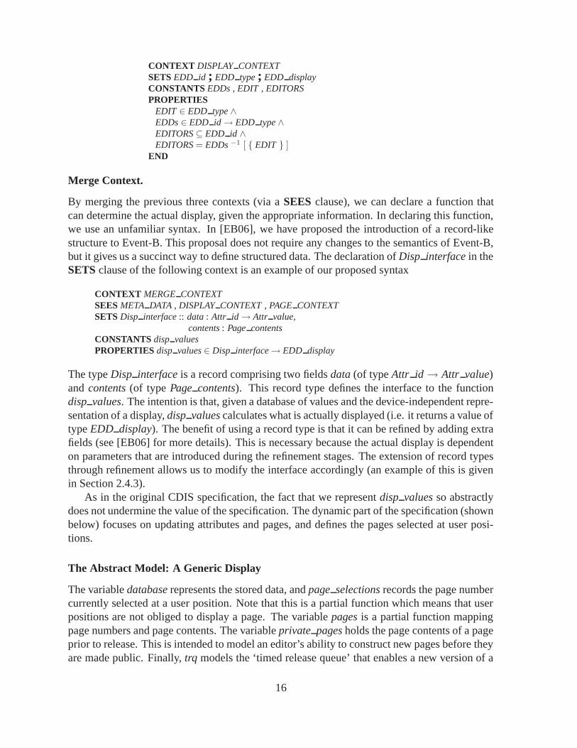
Merge Context.
By merging the previous three contexts (via a SEES clause), we can declare a function thatcan determine the actual display, given the appropriate information. In declaring this function,we use an unfamiliar syntax. In [EB06], we have proposed the introduction of a record-likestructure to Event-B. This proposal does not require any changes to the semantics of Event-B,but it gives us a succinct way to define structured data. The declaration of Disp interface in theSETS clause of the following context is an example of our proposed syntax
CONTEXT MERGE CONTEXTSEES META DATA , DISPLAY CONTEXT , PAGE CONTEXTSETS Disp interface :: data : Attr id→ Attr value,
contents : Page contentsCONSTANTS disp valuesPROPERTIES disp values ∈ Disp interface→ EDD display
The type Disp interface is a record comprising two fields data (of type Attr id → Attr value)and contents (of type Page contents). This record type defines the interface to the functiondisp values. The intention is that, given a database of values and the device-independent repre-sentation of a display, disp values calculates what is actually displayed (i.e. it returns a value oftype EDD display). The benefit of using a record type is that it can be refined by adding extrafields (see [EB06] for more details). This is necessary because the actual display is dependenton parameters that are introduced during the refinement stages. The extension of record typesthrough refinement allows us to modify the interface accordingly (an example of this is givenin Section 2.4.3).
As in the original CDIS specification, the fact that we represent disp values so abstractlydoes not undermine the value of the specification. The dynamic part of the specification (shownbelow) focuses on updating attributes and pages, and defines the pages selected at user posi-tions.
The Abstract Model: A Generic Display
The variable database represents the stored data, and page selections records the page numbercurrently selected at a user position. Note that this is a partial function which means that userpositions are not obliged to display a page. The variable pages is a partial function mappingpage numbers and page contents. The variable private pages holds the page contents of a pageprior to release. This is intended to model an editor’s ability to construct new pages before theyare made public. Finally, trq models the ‘timed release queue’ that enables a new version of a
16

page to be stored until a given time is reached, whereupon it is made public.
MACHINE ABS DISPLAYSEES
META DATA, DISPLAY CONTEXT, PAGE CONTEXT, MERGE CONTEXTVARIABLES database , pages , page selections , private pages , trqDEFINITIONS
inv =database : Attr id→ Attr value ∧pages : Page number �→ Page contents ∧page selections : EDD id �→ Page number ∧private pages : Page number �→ Page contents ∧trq : Page number �→ Page contents ∧ran(page selections)⊆ dom(pages)
INVARIANT invINITIALISATION database , pages , page selections , private pages , trq : ( inv )
Note that, in addition to type information, the invariant insists that pages can be selected onlyif they have contents. We keep the model simple by initialising the system to be any state inwhich the invariant holds.
Almost all of the operations given below correspond to operations defined in the originalVDM specification. One exception is the VIEW PAGE operation that uses the disp valuesfunction to output an actual display. This is a departure from the original VDM specificationbut, since outputs must be preserved during refinement, it forces us to ensure that the appear-ance of actual displays is preserved.
UPDATE DATABASE models the automatic update of data via the stream of data com-ing from the airports, and SET DATA VALUE models the manual update of values (by ed-itors). DISPLAY PAGE enables any user to select a new page to be displayed, and DIS-MISS PAGE removes a page selection. RELEASE PAGE makes a private page public, andDELETE PAGE enables an editor to delete the contents of a page. In addition to the man-ual release of pages (via RELEASE PAGE), pages can be released automatically at specifictimes. RELEASE PAGES FROM TRQ models the timed release of pages. However, atthis stage no notion of time exists in the specification. Therefore, this operation selects an ar-bitrary subset of the pages from trq to be released. This is refined when we introduce a notionof time (as shown in Section 2.4.3). The operations use common B operators such as functionoverriding <+ , domain subtraction−�, and range subtraction −�.
17

UPDATE DATABASE ( ups ) =PRE
ups ∈ Attr id �→ Attr valueTHEN
database := database <+ upsEND ;
SET DATA VALUE ( ei , ai , av ) =PRE
ei ∈ EDD id ∧ai ∈ Attr id ∧ av ∈ Attr value
THENWHEN ei ∈ EDITORS THEN
database ( ai ) := avEND
END ;
DISPLAY PAGE ( ei , no ) =PRE
ei ∈ EDD id ∧ no ∈ Page numberTHEN
WHEN no ∈ dom ( pages ) THENpage selections ( ei ) := no
ENDEND ;
DISMISS PAGE ( ei ) =PRE ei ∈ EDD id THEN
WHENei ∈ dom ( page selections )
THENpage selections :={ ei } −� page selections
ENDEND ;
ed←− VIEW PAGE ( ei ) =PRE ei ∈ EDD id THEN
ANY di WHEREei ∈ dom ( page selections ) ∧di ∈ Disp interface ∧data ( di ) = database ∧contents ( di ) =
pages ( page selections ( ei ) )THEN
ed := disp values ( di )END
END
RELEASE PAGE ( no ) =PRE no ∈ Page number THEN
WHENno ∈ dom ( private pages )
THENpages ( no ) :=
private pages ( no ) ‖private pages :={ no } −� private pages
ENDEND ;
RELEASE PAGES FROM TRQ =ANY SS WHERE
SS ∈Page number �→ Page contents ∧
SS ⊆ trqTHEN
pages := pages <+ SS ‖trq := trq − SS
END ;
DELETE PAGE ( ei , no ) =PRE
ei ∈ EDD id ∧no ∈ Page number
THENWHEN ei ∈ EDITORS THEN
pages := { no } −� pages ‖private pages :={ no } −� private pages ‖
trq := { no } −� trq ‖page selections :=
page selections −� { no }END
END ;
18

MODELTIMED
MODELREVEAL/CONCEAL
MODELCOMBINED
MODELABSTRACT
r1 r2
r1’r2’
Figure 2.3: Non-linear refinement
2.4.3 Refinement
The abstract specification described in the previous section omitted many of the features thatcharacterise CDIS. However, this made it possible to give a broad overview of the system,including its state variables and operations, within a few pages. Now we use this specificationas a basis for refinement in which the omitted details are introduced.
One thing that becomes apparent when using this approach is the lack of order which dic-tates the sequence of refinements. In the case of CDIS, the way that information recorded in thedatabase is displayed depends on several (unrelated) things. For example, values are colouredaccording to their age. By adding a notion of time, via refinement, it is possible to model suchbehaviour. In addition, the model is refined by adding a reveal/conceal feature that enables theair traffic controllers to display or remove ‘page overlays’ from a screen. The order in whichthese features are introduced to the specification is arbitrary since one feature does not dependon the other. Enforcing a linear refinement policy in which one feature had to be introducedafter the other would be inconvenient because it would be easier to understand a refinementthat adds a reveal/conceal feature to the abstract model (see Section 2.4.3) rather than add it tothe timed model shown in Section 2.4.3. Similarly the timed model of Section 2.4.3 is easier toappreciate without the reveal/conceal feature of Section 2.4.3. It would be desirable, therefore,to refine the abstract model in two separate ways and then combine the results. This is depictedin Figure 2.3. Note that the refinements introducing time (r1 and r1′) are not identical, but areclosely related (similarly for r2 and r2′).
19

Adding Time
In terms of the CDIS subset, there are two main reasons for adding time: each piece of airportdata has an age which affects how it is displayed, and the version of each page that is displayedis also time-dependent. In this refinement we shall once again use our proposed syntax forrecord types [EB06].
Time Context.
We begin by introducing a new context to the development. The set Date time represents all ofthe different points in time. We also include a total ordering relation (leq) between these points.
CONTEXT TIMESETS Date timeCONSTANTS leqPROPERTIES
leq ∈ Date time↔ Date time ∧∀ (a).(a : Date time⇒ (a, a) : leq) ∧∀ (a, b).(a : Date time ∧ b : Date time⇒
((a, b) : leq ∧ (b, a) : leq⇒ a = b) ∧((a, b) : leq ∨ (b, a) : leq)) ∧∀ (a, b, c).(a : Date time ∧ b : Date time ∧ c : Date time⇒
((a, b) : leq ∧ (b, c) : leq⇒ (a, c) : leq))END
Meta Data Context.
In order to record the age of a piece of data as well as its value, we refine the META DATAcontext by defining a record type Attrs with two fields value and last update.
CONTEXT META DATA1SEES META DATA , TIMESETS Attrs :: value : Attr value,
last update : Date timeEND
Note that the range of value is of our original value type Attr value. The gluing invariant of therefined model will ensure that the values of the entries in the refined database will match thecorresponding entries in the original database. (This technique of ‘wrapping’ an abstract typein a refined type occurs frequently in our approach.) The field last update (of type Date time)records the time at which the value of the attribute was last updated.
Pages Context
We proceed by refining the pages context in a similar manner. We declare a record type Pagewith two fields: page contents holds the structure of a page, and creation date holds the timeat which a page was created. Note that this has nothing to do with the time at which the page isreleased. In order to model the timed release queue faithfully, we must associate a release datewith every page on the queue. By using our proposed syntax for record refinement [EB06], thisis achieved by defining a subtype of Page (called Rel page) whose elements have an additionalfield called release date.
20

CONTEXT PAGE CONTEXT1SEES TIME , PAGE CONTEXTSETS
Page :: page contents : Page contents,creation date : Date time ;
Rel page SUBTYPES Page WITH release date : Date timeEND
Only pages of type Rel page occur on the timed release queue. We shall see how the refinementof the operation RELEASE PAGES FROM TRQ uses this additional information.
Merge Context.
Now that we have introduced a notion of time, the display function disp values can be aug-mented so that the ages of the data in the database is taken into account when they are displayed.We change the interface of the function by adding a new field to Disp interface called time.The operator ‘EXTEND’ is similar to the ‘SUBTYPES’ operator, but it adds fields to all ele-ments of the record type.
CONTEXT MERGE CONTEXT1SEES
META DATA , DISPLAY CONTEXT , PAGE CONTEXT ,TIME , META DATA1, PAGE CONTEXT1 , MERGE CONTEXT
SETS EXTEND Disp interface WITH time : Date timeEND
Whenever the function disp values is called, the current time can be passed as a parameterso that the ages of the relevant data can be determined. In CDIS, the colour of a value whendisplayed indicates its age (although this detail is not included at this level of abstraction).
The Refined Model: A Timed Display.
The state variables and the operations of ABS DISPLAY are refined to incorporate the timedcontext. Four of the variables in the refinement replace those of the abstract model. The in-variant gives the relationship between these concrete variables and their abstract counterparts.For example, the abstract variable database is refined by timed database, and they are re-lated because the attribute values held in database can be retrieved from the value fields intimed database.
REFINEMENT ABS DISPLAY1REFINES
ABS DISPLAYSEES
META DATA, DISPLAY CONTEXT, PAGE CONTEXT, MERGE CONTEXT,TIME , META DATA1 , PAGE CONTEXT1 , MERGE CONTEXT1
VARIABLEStimed database ,page selections ,timed pages ,private timed pages ,
21

dated trq ,time now
DEFINITIONSinv1 =
timed database ∈ Attr id→ Attrs ∧timed pages ∈ Page number �→ Page ∧private timed pages ∈ Page number �→ Page ∧dated trq ∈ Page number �→ Rel Page ∧time now ∈ Date time ∧database = ( timed database ; value ) ∧ran ( page selections ) ⊆ dom ( timed pages ) ∧pages = ( timed pages ; page contents ) ∧private pages = ( private timed pages ; page contents ) ∧trq = ( dated trq ; page contents ) ∧∀ n . ( n ∈ dom ( timed pages )⇒
( creation date ( timed pages ( n ) ), time now ) ∈ leq ) ∧∀ n . ( n ∈ dom ( private timed pages )⇒
( creation date ( private timed pages ( n ) ), time now) ∈ leq ) ∧∀ n . ( n ∈ dom ( dated trq )⇒
( creation date ( dated trq ( n ) ), time now) ∈ leq )INVARIANT inv1
Some of the operations affected by the refinement are shown below.
UPDATE DATABASE ( ups ) =PRE ups ∈ Attr id �→ Attr value THEN
ANY ff WHEREff ∈ Attr id �→ Attrs ∧dom ( ff ) = dom ( ups ) ∧( ff ; value ) = ups ∧( ff ; last update ) = dom ( ff ) × { time now }
THENtimed database := timed database <+ ff
ENDEND
The parameter to the UPDATE DATABASE operation maintains its type, but the ANY clauseis used to construct a new mapping from Attr id to Attrs all of whose last update componentsare assigned to the current time (to reflect the time of the update). This mapping is used tooverwrite the appropriate entities in the timed database. An interesting refinement occurs inthe operation RELEASE PAGES FROM TRQ. Rather than selecting an arbitrary subset oftrq to release, time now is used to select those elements whose release date is earlier than thecurrent time. The released pages (held in timed pages) are updated accordingly.
RELEASE PAGES FROM TRQ =LET SS BE SS =
dated trq � { rp | rp ∈ Rel Page ∧ ( release date ( rp ) , time now) ∈ leq }IN
timed pages := timed pages <+ SS ‖dated trq := dated trq − SS
END
Next, we introduce a new operation, called CLOCK that increases the current time by someunspecified amount. This operation models the passing of time.
22

CLOCK =ANY time next WHERE
time next ∈ Date time ∧(time now , time next) ∈ leq ∧time next �= time now
THENtime now := time next
END
A Different Refinement: Page Overlays
Now we consider an alternative refinement to the abstract model in which the reveal/concealfeature is added rather than time. First we augment the relevant context PAGE CONTEXT
MACHINE PAGE CONTEXT2SEES
PAGE CONTEXTSETS
Graphic background ;Overlay Page contents SUBTYPES Page contents WITH overlay : Graphic background
END
This definition adds the field Overlay Page contents to a subset of all page contents (i.e. thosepages that possess an overlay). Now we can augment the model by introducing a new variableconcealed displays to record which displays are concealing their overlays.
REFINEMENT ABS DISPLAY2REFINES
ABS DISPLAYSEES
META DATA , DISPLAY CONTEXT , PAGE CONTEXT ,PAGE CONTEXT1 , MERGE CONTEXT
VARIABLESdatabase ,pages ,page selections ,private pages ,trq ,concealed displays
DEFINITIONSinv2 =
concealed displays ⊆ EDD id ∧concealed displays ⊆ dom ( page selections )
INVARIANTinv2
In a similar manner to the timed refinement, the operations of the abstract model are refinedto incorporate reveal/conceal behaviour. In this case we introduce operations to model theusers’ ability to toggle between revealing and concealing overlays on their displays. It is not
23

important to understand the details of the operation RELEASE PAGES FROM TRQ, butit is important to note the structure of the operation because it will influence the structure of thecorresponding operation in the combined model of Section 2.4.3.
RELEASE PAGES FROM TRQ =ANY SS WHERE
SS ∈ Page number �→ Page contents ∧SS ⊆ trq
THENLET p nums BE
p nums = { no | no ∈ dom ( SS ) ∧ no ∈ dom ( pages ) ∧pages ( no ) ∈ Overlay Page contents ∧SS ( no ) �∈ Overlay Page contents }
INLET edd ids BE
edd ids = dom ( page selections � p nums )IN
pages := pages <+ SS ‖trq := trq − SS ‖concealed displays := concealed displays − edd ids
ENDEND
END ;
TOGGLE REVEAL CONCEAL ( ei ) =PRE ei ∈ EDD id THEN
SELECT ei ∈ concealed displays THENconcealed displays := concealed displays− { ei }
ENDEND ;
TOGGLE REVEAL CONCEAL2 ( ei ) =PRE ei ∈ EDD id THEN
SELECTei ∈ dom ( page selections ) ∧pages ( page selections ( ei ) ) ∈ Overlay Page contents ∧ei �∈ concealed displays
THENconcealed displays := concealed displays ∪ { ei }
ENDEND
Putting the Refinements Together
Now that we have two distinct refinements of the same abstract model, the next step is tocombine them into a single model that refines both of them (as in the COMBINED MODELdepicted in Figure 2.3). We do this in a systematic way to promote the idea that the combinationof non-linear refinements could be done automatically.
The combined context is simply the amalgamation of the sets, constants and properties ofthe contexts PAGE CONTEXT1 and PAGE CONTEXT2. This can be achieved via the SEESclause, but for completeness we show this union as a third context COMBINED PAGE CONTEXT.
24

CONTEXT COMBINED PAGE CONTEXTSEES TIME , PAGE CONTEXTSETS
Page :: page contents : Page contents,creation date : Date time ;
Rel page SUBTYPES Page WITH release date : Date time ;Graphic background ;Overlay Page contents SUBTYPES Page contents WITH overlay : Graphic background
END
The model is constructed by amalgamating the variables of both refined models and takingthe conjunction of their invariants. Note that the consistency of the individual refinements ispreserved by the combination because the variables of the separate refinements are distinct. Al-though proof obligations are still generated by the tool, the proofs follow those of the individualrefinements. Future work aims to show that such combinations can be done without the need togenerate further proof obligations. In other words, consistency is preserved by this procedure.
REFINEMENT COMBINED ABS DISPLAYREFINES
ABS DISPLAYSEES
META DATA, DISPLAY CONTEXT, PAGE CONTEXT, MERGE CONTEXT,TIME , META DATA1 , PAGE CONTEXT1 , MERGE CONTEXT1
VARIABLEStimed database ,page selections ,timed pages ,private timed pages ,dated trq ,time now ,concealed displays
INVARIANTinv1 ∧ inv2
Combining the operations is a bit more tricky, but typically this consists of taking the con-junction of (i.e. strengthening) the guards, and composing the bodies of the operations via theparallel operator ‖.
25

RELEASE PAGES FROM TRQ =LET SS BE SS =
dated trq � { rp | rp ∈ Rel Page ∧ ( release date ( rp ) , time now) ∈ leq }IN
LET p nums BEp nums = { no | no ∈ dom ( SS ) ∧ no ∈ dom ( timed pages ) ∧
timed pages ( no ) ∈ Overlay Page contents ∧SS ( no ) �∈ Overlay Page contents }
INLET edd ids BE
edd ids = dom ( page selections � p nums )IN
timed pages := timed pages <+ SS ‖dated trq := dated trq − SS ‖concealed displays := concealed displays− edd ids
ENDEND
END
It can be seen that this operation combines the features of the corresponding operations in theindividual refinements.
2.5 Case Study 5: Ambient Campus
Mobile agent systems are increasingly attracting attention of software engineers. However,issues related to fault tolerance and exception handling in such systems have not yet received thelevel of attention they deserve. In particular, formal support for validating the correctness androbustness of fault tolerance properties is still under-developed. Within the Ambient Campuscase study, we developed an initial approach to dealing with such issues in the context of aconcrete system for dealing with mobility of agents (CAMA), and a concrete technique forverifying their properties (partial order model checking). An overall goal of this strand of ourwork is a formal model for the specification, analysis and model checking of CAMA designs.To achieve it, we use process algebras and high-level Petri nets.
In concrete terms, our approach reported in [IKKR05] is first to give a formal semantics(including a compositional translation) of a suitably expressive subset of CAMA in terms of anappropriate process algebra and its associated operational semantics. The reason why we chosea process algebra semantics is twofold: (i) process algebras, due to their compositional andtextual nature, are a formalism which is very close to the actual notations and languages usedin real implementations; and (ii) there exists a significant body of research on the analysis andverification of process algebras. In our particular case, there are two process algebras which aredirectly relevant to CAMA, viz. KLAIM [DNLM05, DNFP98] and π-calculus [Par01], and ourintention is to use the former as a starting point for the development of the formal semantics.
The process algebra semantics of CAMA can then be used as a starting point for developingefficient model checking techniques aimed at verifying the behavioural correctness of CAMA
designs. In our approach, we are specifically interested in model checking techniques whichalleviate the state space explosion problem, and for this reason we adopted a partial order modelchecking based on Petri net unfoldings [Kho03]. To be able to use it, we will take advantage of
26
a semantics preserving translation from the process terms used in the modelling of CAMA to asuitable class of high-level Petri nets based on [DKK06b, DKK06a].
CAMA is a middleware supporting rapid development of mobile agent software. It offers aprogrammer a number of high-level operations and a set of abstractions which help to developmulti-agent applications in a disciplined and structured way. CAMA is an extensible system. Itsinter-agent communication is based on the LINDA paradigm which provides a set of language-independent coordination primitives that can be used for coordination of several independentpieces of software. They allow processes to put tuples (vectors of values) in a shared tuplespace, remove them, and test for their presence. Input operations use special tuples calledtemplates, where some fields are replaced with wildcards that can match any value.
The approach taken in the Ambient Campus case study is based on the asymmetric modelof agent systems within the location-based paradigm. The main part of communication andcontrol is implemented by a dedicated service, called location. The approach supports large-scale mobile agent networks in a predictable and reliable manner. Moreover, location-basedarchitecture eliminates the need for employing complex distributed algorithms, such as votingor agreement.
27

Chapter 3
Discussion of issues
3.1 Towards an Algebra of Abstractions for CommunicatingProcesses
It is often desirable to describe the interface of an implementation system at a different (usu-ally more detailed) level of abstraction to the interface of the relevant specification. This callsfor a relation aimed at formalising the notion that a process is an acceptable implementationof another target process in the event that they possess different interfaces. Let us consider aspecification network, Pnet, composed of n communicating processes P1, . . . , Pn, and a corre-sponding implementation network, Qnet, also composed of n processes, Q1, . . . , Qn. Intuitively,Pi is intended to be Qi’s specification; we shall also refer to Pi as a target or base system, andto Qi as a source or implementation system. Note that although Pi’s and Qi’s interfaces neednot coincide, we do assume that the interface of Qnet at the boundary with the external envi-ronment is the same as that of Pnet (see Figure 3.1), and that we are not interested in the detailsof inter-process communication within the networks Pnet and Qnet. In the CSP notation, thismeans that the specification network Pnet is of the form (P1‖P2‖ · · · ‖Pn)\A, where A is the setof actions used for the internal communication by the Pi’s, while the implementation networkis of the form Qnet = (Q1‖Q2‖ · · · ‖Qn) \ B, where B is the set of actions used for the internalcommunication by the Qi’s.
P1 P2 P3a b
Pnetc
c
��
��
��
Q1 Q2 Q3a b
Qnet
Figure 3.1: Network connectivity where pairs of corresponding processes, Qi and Pi, may havedifferent observable actions.
In the usual treatment of process algebras, such as [Mil89, Ros98], the notion that Qnet
28

P1 P2 P3a b
Pnetc
c
��
��
��
Q1 Q2 Q3a b
Qnet
Figure 3.2: Network connectivity where each Qi has the same observable actions as Pi.
implements Pnet is based on the idea that Qnet is more deterministic than (or equivalent to) Pnet
in terms of the chosen semantics. In practice, to formally verify that such a property holds, onecan proceed in either of the following two ways.
• The first approach is to compare Pnet and Qnet according to a chosen notion of refinementor equivalence. This is a straightforward approach, but one which potentially suffers froma severe state space explosion, since the compared processes are obtained by combiningn components.
• The second, usually much better, approach attempts to (i) show an appropriate refine-ment or equivalence holds for each pair of processes Pi and Qi, and (ii) resort to generaltheorems to infer the desired relation between the complete networks, Pnet and Qnet.
Within the standard approaches, such as [Mil89, Ros98], the latter compositional way of prov-ing correctness of the implementation network is handled only in the case when for each i,Pi and Qi have the same actions in their interfaces. Hence the networks in Figure 3.1 cannotreally be treated by this technique, as the constituent processes should be like in Figure 3.2.Yet in deriving an implementation from a specification we will often wish to implement ab-stract, high-level interface actions at a lower level of detail and in a more concrete manner. Forexample, the link available to connect base components Pi, Pj may be unreliable, and so mayneed to be implemented, in the sources Qi, Qj, by a pair of channels, one for data and one foracknowledgements. Or an intended implementation Qi of Pi may be liable to fail itself, so thatthe final implementation Qi is built by assembling redundant replicas of Qi, and thus has eachchannel of Pi replicated [Lam78] (such a scenario was one of the original motivations behindthe work [KMP97] of which this paper is a continuation). Or it may simply be the case that ahigh-level action of Pi is rendered in a more concrete, and hence more implementable, form.As a result, the interface of an implementation process may exhibit a lower (and so different)level of abstraction than a specification process.
In the process algebraic context, dealing with interface difference necessitates the devel-opment of what Rensink and Gorrieri [RG01] have termed a vertical implementation relation.This should adequately capture the nature of the relationship between a specification and animplementation whose interfaces differ; and should collapse into the standard, horizontal onewhenever the two interfaces happen to coincide. In works [KMP97, BKPPK02, BKP04], we in-dependently identified this ‘collapsing’ requirement as accessibility or realisability, effectivelypioneering it within the CSP process model [Ros98].
29
Technically, in our preceding works [BKPPK02, BKP04], processes are formalised usingthe CSP language, with its standard failures-divergences semantics [Ros98]. The implemen-tation relation is formulated in terms of failures and divergences of the implementation andtarget processes. Interface difference is modelled by endowing the implementation relationwith parameters called extraction patterns. These are intended to interpret implementation be-haviour as target behaviour (translating, in particular, traces), and suitably constrain the formerin connection to acceptable refusals.
We developed the theory of [BKPPK02, BKP04] under that crucial restriction of the one-to-one communication paradigm. That is, we assumed no communication action is shared bymore than two processes within a distributed network of processes (as is the case in Figure 3.1).This, in particular, excluded systems with broadcast, as well as disallowed, say, a potentiallycomplex group protocol at the implementation level to be abstracted into a single action atthe specification level. Another limitation of [BKPPK02, BKP04] was that it only establishedthe implementation relation to distribute over network composition (i.e. compositionality), notother useful operations employed to combine and construct processes, notably choice.
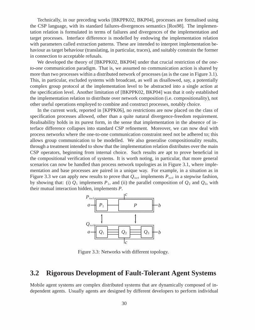
In the current work, reported in [KPPK06], no restrictions are now placed on the class ofspecification processes allowed, other than a quite natural divergence-freedom requirement.Realisability holds in its purest form, in the sense that implementation in the absence of in-terface difference collapses into standard CSP refinement. Moreover, we can now deal withprocess networks where the one-to-one communication constraint need not be adhered to; thisallows group communication to be modelled. We also generalise compositionality results,through a treatment intended to show that the implementation relation distributes over the mainCSP operators, beginning from internal choice. Such results are apt to prove beneficial inthe compositional verification of systems. It is worth noting, in particular, that more generalscenarios can now be handled than process network topologies as in Figure 3.1, where imple-mentation and base processes are paired in a unique way. For example, in a situation as inFigure 3.3 we can apply new results to prove that Qnet implements Pnet in a stepwise fashion,by showing that: (i) Q1 implements P1, and (ii) the parallel composition of Q2 and Q3, withtheir mutual interaction hidden, implements P.
P1 Pa b
Pnetc
c
��
��
Q1 Q2 Q3a b
Qnet
Figure 3.3: Networks with different topology.
3.2 Rigorous Development of Fault-Tolerant Agent Systems
Mobile agent systems are complex distributed systems that are dynamically composed of in-dependent agents. Usually agents are designed by different developers to perform individual
30

computational tasks. The agent technology naturally solves the problem of partitioning com-plex software into smaller parts that are easier to analyse, design and maintain. However, toensure interoperability of agents, the individual developments should adhere to a certain “stan-dard”, which would guarantee compatibility of constructed agents yet avoid over-constrainingthe development process. Middleware supporting agent execution is also distributed. In thiswork we show how to formally develop a distributed middleware in such a way that its differentparts can be taken apart and implemented independently [ILRT06].
The initial results of this work were applied in the development of the CAMA (Context-Aware Mobile Agents) middleware system [AIR06, Ili06]. The core part of the middleware– the scoping mechanism [IR05] – was formally designed and then implemented according tothe resultant specification [ILRT05]. For other parts, such as disconnection toleration and agentrecovery results of the formal development helped to re-engineer the middleware implementa-tion.
We start from an abstract specification of the overall agent system, i.e., abstractly modelagents together with the location supporting inter-agent communication. In a number of cor-rectness preserving steps we incorporate various system properties, including fault tolerance,into the specification. Finally, we arrive at the specification of entire middleware, which can bedecomposed into parts to be implemented by the location and by each individual agent.
In the independent development of individual agents the programmers merely need to aug-ment this abstract part with an implementation of the desired agent functionality. Such anapproach allows us to ensure inter-operability of individually developed agents and the cor-rectness of the overall system. Moreover, since the proposed patterns contain abstract specifi-cations of the means for detecting agent failures, such as disconnections and crashes, and thecorresponding error recovery procedures, we can guarantee fault tolerance of an agent systemdeveloped according to the proposed approach.
One of the major challenges in designing agent systems lies in ensuring interoperability ofagents. This problem can only be properly addressed if we define the essential properties of theoverall agent system, derive the properties to be satisfied by the location and each agent, andensure that they are preserved in the agent and location development. This goal can be achievedby adopting the system approach to developing agent systems, i.e., modelling the entire set ofagents together with the location that provides the infrastructure for agent communication.
3.2.1 Fault-tolerance
One of the essential requirements of multi-agent systems is the ability to operate in a volatile,error prone environment. Hence we aim at developing fault tolerant agent systems, i.e., systemswhich can withstand various kinds of faults. The most typical class of faults in our case isa temporal loss of connection. It might cause errors or delays in communication betweencooperating agents. In our first refinement step we introduce an abstract representation of thistype of fault.
In most cases an agent loses connection only for a short period of time. After connectionis restored, the agent is willing to continue its activities virtually uninterrupted. Therefore, af-ter detecting connection loss, the location should not immediately disengage the disconnectedagent but rather set a deadline before which the agent should reconnect. If the disconnectedagent restores its connection before the deadline then it can continue its normal activity. How-ever, if the agent fails to do it, the location should disengage the agent.
31

This behaviour can be formally modelled by the timeout mechanism. Upon detecting dis-connection the location activates a timer. If the agent reconnects before the timeout then thetimer is stopped. Otherwise, the location forcefully disengages the disconnected agent.
During the formal development of the system we use a combination of the superpositionrefinement and atomicity refinement. With atomicity refinement a single event is refined into aset of events. A simple abstract event can be represented as of alternative events and this allowsuse to explicitly introduce normal behaviour and recovery actions.
The net direction of refinement is a providing a finer recovery actions for agent failures.Initially, any agent failure is treated as an unrecoverable error. Upon detecting an error, thefailed agent is removed from the scope and disengaged from the location. In our next refinementstep we distinguish between recoverable and unrecoverable errors. Namely, upon detecting anerror the agent at first tries to recover from it (probably involving some other agents into theerror recovery). If the error recovery eventually succeeds then the normal operational state ofthe agent is restored. Otherwise, the error is treated as unrecoverable.
While specifying error recovery procedures, it is crucial to ensure that the error recoveryterminates, i.e., does not continue forever. To ensure this, we introduce the variable whichlimits the amount of error recovery attempts for each agent. Each attempt of error recoverydecrements this value by one. When for some agent the recovery limit becomes zero then agenterror recovery terminates and the error is treated as unrecoverable.
3.2.2 Interoperability
At the initial stages of the system development we mainly focused on modelling interactions ofagents with the location. We proceed by introducing an abstract representation of the scopes asan essential mechanism which governs agent interactions while they are involved in cooperativeactivities.
The scoping mechanism has a deep impact on modelling error recovery in agent systems.For instance, if a scope owner irrecoverably fails, then, to recover the system from this error,the location should close the affected scope and force all agents to leave.
Each scope provides the isolated coordination space for compatible agents to communicate.Compatibility of agents is defined by their roles – abstract descriptions of agent functionality.To ensure compatibility of agents in a scope, each scope supports a certain predefined set ofroles. When an agent joins a scope, it chooses one of the supported roles. We assume that anagent can join a scope only in one role and this role remains the same while the agent is in thescope. However, an agent might leave a scope and join it in another role later.
The creator of the scope defines the minimal and maximal numbers of agents that are al-lowed to play each supported role. This is dictated by the logical conditions on the scopefunctionality. For instance, if the scope is created for purchasing a certain item on an electronicauction then there are must be only one seller and at least one buyer for a scope to functionproperly.
However, agent systems are asynchronous systems. Therefore, at the time of scope creationit cannot be guaranteed that agents will take all the required roles in the right proportions atonce and the scope will instantly become functional. Since agents join and leave the scopearbitrarily, the scope can be in various states at different instances of time: pending, when thenumber of agents is still insufficient for normal functioning of the scope; expanding, when the
32

scope is functional but new agents can still join it; closed, when the maximal allowed numberof agents per each role is reached.
3.2.3 Conclusion
In our development we adapted the system approach, i.e., captured the behaviour of agentstogether with their communication environment. While carrying out the development of thesystem by refinement, we modelled the essential properties of agent systems and incorporatedfault tolerance mechanisms into the system specification. We demonstrated how to define themechanisms for tolerating agent disconnections typical for mobile systems as well as agentcrashes.
The proposed approach provides the developers of agent systems with a formal basis forensuring inter-operability of independently developed agents. Indeed, by decomposing theproposed formal model of the middleware into the parts to be implemented by the agents andby the location and ensuring adherence of their implementations to these specifications, we canensure agent inter-operability.
3.3 Deriving specifications
The research on “Deriving Specifications” was reported on in §2.2.1 of (D9) the Preliminaryreport on methodology.1 The “HJJ approach” (after the initial letters of the family names of thethree authors) was first set out in [HJJ03]. Not only has this research continued, it is clear thatit is attracting significant attention. We will not report the technical details here since adequatematerial can be cited.
As an update on the state as in D9, we can report
• Ian Hayes (University of Queensland) presented the HJJ method at the REFT workshopassociated with FM-06.
• Cliff Jones based his keynote talk at DSVIS-05 on the HJJ method; in particular, headdressed the application of the method to those systems which include human players(see [Jon05d]).
• Joey Coleman presented a joint (with Cliff Jones) paper on the ideas at the REFT work-shop associated with FM-06 [CJ05].
• Joey Coleman wrote up the REFT presentation as a (solo) paper [Col06].
• Cliff Jones based his invited talk at the IEEE ICECCS-2005 seminar in Shanghai on theHJJ approach [Jon05c]
• A journal submission (see [JHJ06] for a pre-print) has been made by the original threeHJJ authors to Acta Informatica.
• Cliff Jones has given several seminars on this topic including ones at an IFIP event(VSTTE) in Zurich and FM-E/FACS.
1Cliff Jones also described this work to the first Rodin Review in Brussels on 2005-09-30.
33
• This last talk led to a “rebuttal” talk by Prof Tom Maibuam (Canada) in which he debatedseveral of the technical decisions in HJJ approach (June 2006, London BCS HQ).
There clearly remains research to be done on HJJ. Of particular relevance to Rodin is thefact that the journal paper [JHJ06] stops short of giving a semantics for ways of combiningwhole specifications.
3.4 Synthesis of Scenario Based Test Cases from B Models
Software models are usually built to reduce the complexity of the development process and toensure software quality. A software model is an abstraction in the sense that it captures the mostimportant requirements of the system while omitting unimportant details. A model is usually aspecification of the system which is developed from the requirements early in the developmentcycle [DJK+99]. This paper concerns with formal models only; in particular, we deal withmodel oriented formal languages like Z [Spi88], VDM [Jon90b] and B [Abr96]. By modeloriented we mean, the system behaviour is described using an explicit model of the systemstate along with operations on the state. We will focus on B models only.
Model based testing is usually based on the notion of a coverage graph obtained fromthe symbolic execution of the model. A subset of the paths in this graph can be treated asa test suite from the viewpoint of test case generation. Even though model based testing isan incomplete activity, the selected behaviours could be made effective in the sense that theycapture the interesting activities of the system and hence the success of their testing would giveus confidence about its correctness.
Existing testing tools or techniques [BLLP04, SLB05] dealing with model oriented lan-guages partition the input space of the operations into equivalence classes to create operationinstances. Then a Finite State Automaton (FSA) or a coverage graph is constructed in whichthe initial node corresponds to the initial state of the model, edges correspond to application ofoperation instances. Usually a coverage graph is constructed up to a predefined depth or size.Some paths of this graph are selected as test cases. When the implementation is subjected tothe same sequence of operations as in a test case, we get an image of the original path in themodel execution. Now if the properties of the implementation path matches with the propertiesof the path in the model, we declare that the implementation has passed the test case; otherwise,a failure.
However, in these approaches, there is no guarantee that the user scenarios are tested. Auser scenario is like a usecase scenario in UML [OMG05]; in this article, we use scenariosand usecases interchangeably. The paths that we test as test cases may bear no resemblanceto the operation sequences in relation to user scenarios. How to know that we are not missingout some scenarios? Of course if all possible operation instances do appear in the coveragegraph, and we are able to test all of them, we can say that the user scenarios have been testedin an implicit way. But since we fix a predefined bound on the depth of the coverage graph,some operation instances may lie beyond this bound, and then there is no way to locate them.Furthermore, some valid operation instance may not appear in the graph at all. In this paper,we address these issues. Of course, here we assume that the entire development path fromthe specification to code is not entirely formal, in which case testing may not be necessary;however, in practice, the entire development process is less often formal.
34

Rk
R2
R1
R0
R(k−1)
T0
T1
T2
T(k−1)
Tk
.
.
.
RefinementChain
Test CaseChain
Figure 3.4: The Basic Idea
The basic idea behind our paper can be seen from Figure 3.4. We define an initial usecase-based test case T0 in terms of a sequence of operations in relation to the initial specification R0.Thereafter, given any successive refinement pair Ri and Ri+1, and Ti as the usecase-based testcase for Ri, we derive Ti+1 such that it is a valid behaviour of Ri+1, and in addition, Ti and Ti+1
are equivalent to each other as far as the original test case is concerned. The main contributionsof our paper are:
• We relate our test cases to user scenarios; in the process, we also find out if the refinementhas missed out on some scenarios.
• We generate a small number of test cases, and our approach is much more focused. Theresult is that the time to execute the test cases becomes smaller.
The organization of this section is as follows. Section 3.4.1 discusses the testing termi-nology we use. Section 3.4.3 describes the problem in a formal manner. In Section 3.4.4, wediscuss our approach over a running example. Section 3.4.10 discusses the strengths and theweaknesses of our approach. Section 3.4.11 concludes the material.
3.4.1 Terminology
A testing criterion is a set of requirements on test data which reflects a notion of adequacy onthe testing of a system [RAO92, ZHM97]. An adequacy criterion serves two purposes: (a) itdefines a stopping rule which determines whether sufficient testing has already been done; so,testing can now be stopped, and (b) it provides measurements to obtain the degree of adequacyobtained after testing stopped. For our purpose, the testing criterion would be to test the use-cases. However, the usecases are usually generic in nature; so the criterion would be to testsome instances of the usecases.
In model based testing, the test cases that are derived from a model always refer to an ab-stract name space. Since they would be used to test the implementation, it is necessary to definea mapping between the abstract name space of the model and the concrete name space of theimplementation. Gannon et al. [GHM97] have termed this as representation Mapping. In thecontext of test oracle generation, there are two types of mappings: control and data [RAO92].
35

Control mappings are between control points in the implementation and locations in the spec-ification; these are the points where the specification and the implementation states are to bematched. Data mappings are transformations between data structures in the implementationand those in the specification.
3.4.2 Existing Approaches
The work by Dick and Faivre [DF93] is a major contribution to the use of formal methods insoftware testing. A VDM specification has state variables and an invariant (Inv) to restrict thevariables. An operation, say OP, is specified by a pre-condition (OPpre) and a post-condition(OPpost). The approach partitions the input space of OP by converting the expression (OPpre ∧OPpost ∧ Inv) into its Disjunctive Normal Form (DNF), and each disjunct, unless a contradic-tion, represents an input subdomain of OP. Next as many operation instances are created as thenumber of non-contradictory disjuncts in the DNF. An attempt is then made to create a FSAin which each node represents a possible machine state and an edge represents an applicationof an operation instance. A set of test cases is then generated by traversing the FSA, each testcase being a sequence of operation instances.
BZ-Testing Tool (BZ-TT)[BLLP04] generates functional test cases from B as well as Zspecifications. The test case generation proceeds in the following steps.
• Each operation is partitioned into a set of operation instances so that each partition corre-sponds to exactly one control path within the operation; the conjunction of all predicatesalong with the postcondition in relation to the control path is called the effect predicateof the operation instance.
• The free state variables in each effect predicate is assigned with their maximum andminimum values to obtain a set of boundary goals. Similarly, boundary input values areobtained by giving maximum and minimum values to the input variables in the effectpredicate.
• A preamble is computed by using a Constraint Logic Programming (CLP) Solver whichfinds a path through symbolic execution from the initial state to a boundary state, a statesatisfying a given boundary goal. And then relevant operation instances are applied atthe boundary state by giving them boundary inputs.
Satpathy et al. [SLB05] discuss the prototype of a tool called ProTest which performstesting of an implementation in relation to its B model. The tool performs partition analysisusing a technique similar to that of Dick and Faivre. A finite coverage graph is created froma symbolic execution of the B model by a model checking tool called ProB [LB05]. Somepaths starting from the initial state are taken as test cases. The ProTest tool can run Javaprograms. So the B model and its implementation are run simultaneously by the tool – theformer symbolically and the latter at the concrete level – in relation to a test case and similarmodel and implementation states are matched to assign a verdict.
All approaches usually partition the input space to create operation instances, but whena specification is further refined, the original partitions may have no meaning in relation tothe refinements because the data space might have changed. Derrick and Boiten [DB99] havedeveloped a strategy to transform the operation instances so that they remain meaningful inrelation to the appropriate refinement.
36

3.4.3 The B Method
The B-method, originally developed by J.-R. Abrial [Abr96], is a theory and methodology forformal development of computer systems. B is used to cover the whole range of softwaredevelopment cycle; the specification is used to generate code with a set of refinement steps inbetween. At each stage, the current refinement needs to be proved consistent with the previousrefinement.
The basic unit of specification in the B-method is called a B machine. Larger specificationscan be obtained by composing B machines in a (tree-like) hierarchical manner. This is a designrestriction on B with a view to making the proofs compositional. An individual B machineconsists of a set of variables, an invariant to restrict the variables, and a set of operations tomodify the state. An operation has a precondition, and an operation invocation is defined onlyif the precondition holds. The initialization action and an operation body are written as atomicactions coded in a language called the generalized substitution language [Abr96]. The languageallows specification of deterministic and non-deterministic operations and assignments. Anoperation invocation transforms a machine state to a new state. The behaviour of a B machinecan be described in terms of a sequence of operations, and the first operation of the sequenceoriginates from the initial state of the machine.
3.4.4 The Problem
It should be clear that, in case of the BZ-TT and ProTest approaches, if all operation instancesdo appear in the coverage graph then, and each such instance is tested, it would imply that allscenarios are covered in an implicit manner. However, usually all such instances do not appear.The reasons are as follows:
• If the model invariant is weak then a valid operation instance may not be reachable. Forinstance, the constraint 10 ≤ X ≤ 20 could be present in a model as 0 ≤ X ≤ 100. If Xin a state has value of 50, then some valid operations may not be applicable and so wouldnot appear in the coverage graph. Usually the invariants suffer from incompleteness.
• A bad initialization may stop some operation instances from appearing.
• An operation instance may not occur because we make a finite construction of the cov-erage graph according to some predefined depth; but, had we continued with graph con-struction, possibly some more instances might have appeared. But the missing operationinstances may be related to the usecases.
3.4.5 Refinement in B
In the B method, the initial specification passes through a succession of refinements and thecode can be generated from the final refinement. In practice, the whole refinement sequenceis generated less often; one approach is to produce a few refinement steps, generate code andthen consistency of the implementation is left to model based testing. Or it could be the casethat only one specification is written and code is written manually in relation to this.
Classical B refinement is expressed in terms of a gluing invariant to link the concrete statesto abstract states. Further, refinement in B method and various tools supporting B is limited to
37

a
c in CI c
GI GI
COP
GI
AOP(exists) a in AI
(exists) a’
c’
Figure 3.5: Relational Definition of Forward Simulation
forward refinement, or downward simulation [Dun03, LB05]. Let us consider two successiverefinements: R1 and R2, the latter being a refinement of the former; i.e., R1 is more abstract inrelation to R2. Let GI be the gluing invariant or relation between them. Furthermore, let AI andCI be the abstract and concrete initial states of the two refinements. Let AOP and COP standfor an abstract operation and its concrete operations in R1 and R2 respectively. Then forwardsimulation as a relational definition is as in Figure 3.5 [HHS86, LB05]. In other words:
• Every concrete initial state must be related to some initial abstract state
• If concrete state c and abstract state a are linked by GI, and a concrete operation COPtakes c to c′, then there must exist an abstract state a′ so that the relationship in thediagram holds.
If R1 and R2 satisfy these relationships then we can say that R2 is consistent with R1. The proofobligations generated by the tools supporting B prove this relationship.
In this background, we will illustrate the problem that we address in our paper. The userscenarios can be described with ease in relation to the initial or the most abstract specification.The initial specification usually has a few high level operations and it would be easy to describeour usecases in terms of these operation sequences, and further the length of these sequenceswould be small. The description of usecases as a linear sequence of operations will be termedas our initial test cases. However, some usecases may be non-terminating. Consider the usecase: send messages; this means any number of messages can be sent. This usecase can beexpressed by the regular expression: send.(send)∗. In such a case, we only take a finite instanceof this as our initial test cases, say the sequence: < send, send, send, send >.
Usually the initial specification undergoes a succession of refinements, and one such re-finement, say Ri, is referred to while writing the code. Let us call this as the implementationrefinement. Now the problem is that our initial test cases in this situation do not hold anyground because the semantic gap between the code and the initial test cases could be very high.Our approach decreases this gap to a desired level. Our approach upgrades the initial test casesto obtain test cases in sync with the implementation refinement. Refer to Figure 3.6. Let usassume that refinement Ri+1 has been obtained from Ri through forward simulation. Further Ri
satisfies test case Ti; in other words, Ti is a valid trace of Ri. Under this scenario, our approachderives a test case Ti+1 which is satisfied by Ri+1, and in addition Ti+1 is a trace refinement ofTi.
38

Ri
Ri+1
Ti
satisfies
satisfies
i+1
GI Trace refinement
(exists) T
Figure 3.6: A step in the synthesis of Test Cases
3.4.6 The Approach
We refer to the initial specification as R0. We are given usecase-based test cases for R0; wehave seen that they are easy to construct in relation to the initial specification. Thereafterwe repeatedly use the simulation diagram of Figure 3.6 to obtain test cases for successiverefinements. This we demonstrate through an example.
3.4.7 An Example
We have taken the leader election problem as our running example. The B machine Leader.mchshows the initial B specification. The Appendix presents this machine along with its two suc-cessive refinements. A finite number of processors are arranged in a ring, each processor has anumeric ID. The processor with the highest numeric value is elected as the leader. So, the onlyusecase would be: elect a leader. There is only one state variable and only one operation calledelect besides the initialization clause. It could be seen that the initial test case in relation to thelone usecase would be: < init, elect >.
LeaderR.mch is the first refinement of Leader.mch. It has two new operations, called ac-cept() and reject() in addition to the operations of the original machine. LeaderRR.mch is arefinement of LeaderR.mch. It has one more new operation called send(). As per the rules ofrefinement a new event introduced in a refinement must terminate. This is usually ensured byassuming a variant and showing that each invocation of the new operation decreases this vari-ant. We will call the new events in a refinement as τ -operations; they are internal operationswhen we view them from its parent refinement. With this background, we will now discuss thealgorithm to synthesize test cases. In this context, we make the following assumptions.
• we assume a flat B machine; i.e., a machine without any hierarchy.
• Each new event introduced through a refinement has an explicit numeric variant which isdecreased after every invocation.
3.4.8 The Algorithm
The Algorithm in Table 3.1 assumes that initial test cases are given, and then it synthesizestest cases for subsequent refinements. We will illustrate our algorithm over the leader election
39

Algorithm: GenerateTestCasesInput: A specification (R0) and K refinements as R1, . . . , RK ,
and GIi is the gluing invariant between Ri and Ri−1.Output: K + 1 test sequences in form of graphs: G0, . . . , GK
step 1:Create K + 1 nodes I0, . . . , IK as initial nodes of G0, . . . , GK .Let Ii receive the assignments of the Initialization clause in refinement i.
step 2Consider all variants in K refinements. Restrict constants and set sizesso that in the worst scenario, the problem size remains small.Based on this, instantiate the IK
step 3:Project Ik backwards to give full instantiation to I0, . . . IK−1.
step 4:Complete a linear path in G0 to represent a user scenario.Each node and edge is to receive instantiation as in symbolic execution.i = 1;
step 5:Looking at Gi−1, construct Gi as follows:Let Gi−1 have t states (nodes) as Ii−1 = A1, . . . , At
for (j = 2, . . . , t) doConstruct for Gi, nodes Bj, and derive assignments to a subset ofstate variables in Bj such that: Bj ∧ GIi ⇒ Aj.Construct a path from Bj−1 to Bj by repeated execution ofτ -operations of Ri.Strategy: Whenever data values are needed for operation parametersselect the data values (closed terms) in Bj
endforstep 6:
if (i = K) stopelse i = i + 1, Goto step 5.
Table 3.1: Algorithm for graph creation
40

INIT
position = ID(M)
elect()
in = {}
INIT
elect()accept() accept ()position =
x = 20
position ={10−>10, 20−>15, 15−>15}
x = 20
position ={10−>10,
15−>15} 20−>10,
GI holds
GI holds
GI holds
INIT
out(20)=15 \/
out(10)=10 \/
out(15)=15 \/nxt(15)=in(15)
out = ID(M)
GI holdsin=
{20−>15}out =
{10−>10,15−>15}
x=20
x=15
send
send
accept
x = 20
send
x=15
(state A0)(A1)
(B0)(B1) (B2)
(C0)
(C1)
(C2)(C3)
(C4) nxt(10)=in(10) ,
nxt(15)=in(20) ,
V2 = 6; next = ...
positionb = ?
GI holds
(B3)
(C10)
v1 = n (n+1)/2
M: subset of Nk in M
winner = k
winner = k1
k1 in M
winner = k2
k2 in M
n = | M |
winner = max (M)
winner = 20
winner = 20
winner = 10 winner = 10
v2 = m(m+1)/2
m = | M |
k2 = 10
k1 = 10
k = 10M = {10,15,20}
ID{10,15,20}
out = ID{10,15,20}
Figure 3.7: Steps in generating the Coverage Graphs
problem as the running example. In the first step, the algorithm creates initial nodes for all therefinements. In Figure 3.7, this is shown by nodes A0, B0, and C0 respectively.
Because of the new events a test case for the current refinement could be larger in size inrelation to the corresponding test case of the previous refinement; the extent to which it couldbe larger is strictly dependent on the variants of the new events in the refinement. As we willsoon discuss, the construction algorithm is of exponential complexity. Therefore, we limit theproblem size by a suitable instantiation. This task is performed by Step 2 in the algorithm.For the present, the problem size is dependent on variants v1 and v2 and they should be givensmall values. For the present and to keep the presentation simple, we give the value of 3 tothe size of set M so that v1 and v2 both get the value of 6. We then can select any valuesfor M, and for the present it is {10, 15, 20}. And then the instantiation of the constant functionnext = {(10, 20), (20, 15), (15, 10) which shows the directions to treat the subset as a ring. Thisinstantiation has been shown in a box on top of node C0.
We first give instantiation to the initial node of the last refinement and then we projectthese instantiations in relation to the gluing invariant backwards so that the initial states of allrefinements receive instantiation. In the algorithm, this is done by step 3. In the example, weproject the instantiation of C0 to B0 and A0. They have been shown in the boxes attached tothe respective nodes.
In step 4 of the algorithm, we symbolically execute the specification (or refinement R0) inrelation to the instantiation and the initial trace. In the process all the nodes in the trace receiveinstantiation. Note this at node A1 in the figure.
41

Step 5 discusses how we take a fully instantiated trace of a refinement and then deriveincrementally a fully instantiated trace of the next refinement. We illustrate this through theexample. < A0, A1 > is a fully instantiated path in R0. Let us assume there exists a state for thefirst refinement having a gluing relation with A1, and let us name it B3. Then from the gluingrelation and the fact that A1 is instantiated, we can give partial instantiation to B3; more aboutthis instantiation latter. Since the gluing relation here is ID (identity function), we have for B3,winner = 20. Next we try to find a path between B0 and B3 such that the final edge wouldbe labelled with elect() and its prefix would consist of edges all labelled with the new events(τ operations). Our algorithm assumes that such a path exists; we will consider the issue ofnon-existence later.
The algorithm for finding the shortest path between two such states is NP-Complete [GJ79]because it is a variant of the satisfiability problem. So, we follow a greedy strategy. The strategystates that whenever you need data values for the τ -operations, always select the values fromthe target state. To be more specific, the data values of the target node has partial instantiation,and some of them may coincide with the data values in the source state. We select values fromthe state variables which differ from the assignments in the source state.
For the current example, we have winner= 20 in the target state; so we try to use thisvalue as parameter to the τ -operations. In the process we create the path < B0, B1, B2, B3 >.We could have applied the other τ -operation reject, but giving it the value of 20 made itsprecondition false.
Thereafter we repeat step 5 to complete the graph construction for all the refinements. Forthe current example, we need to obtain a trace for refinement R2. The gluing relation, say GI1between R1 and R2 is:
position(x) = y⇔ out(x) = y ∨ next(y) = in(x)
We now discover a node to be sync with B1 such that the above gluing relation holds; however,we can discover many nodes denoted by X such that X ∧ GI ⇒ B1, we discover the mostgeneric one. This means that we assign values to the new node X in a conservative manner.For the present C4 is the state which is in sync with B1 in terms of the gluing relation. Notein the Figure 3.7, how assignment of some state variables of C4 have been given in the form ofpredicates.
As per our greedy strategy, whenever we select parameters for the τ -operation send, weselect 15 or 20; this is because these are the places where C0 and C4 differ. In the processwe discover the path < C0, C1, C4 >. Next, we discover a node C10 in sync with node B2.So, now our task is to find a path between C4 till C10 by use of Step 5 once again. And thiscontinues.
3.4.9 Exponential Nature of the Algorithm
Refer to Figure 3.8. The graph at the top shows some traces for refinement R1 and assumethat all the traces shown implement the single trace of R0, its previous refinement. Let usassume this single trace of R0 do correspond to one of the usecases. Now as per the rules ofrefinement, if R2 implements any of the traces of R1 then we are done and we can concludethat R2 implements the original usecase. However, the situation is much more trickier when wehave to show that R2 does not implement the usecase.
42

X
YZ
P Q
For R2
Trace 3
A C
D
G
H
For R1 F
ETrace 1
B
Trace 2
Figure 3.8: Showing non-existence of trace implementation
Let us see how our algorithm works. Consider the situation when the construction for R1 isover and we are dealing with R2. The algorithm first takes the trace < A, B, E > and constructsa path < X, Y, Z, . . . > to show the correspondence. It may so happen that we fail to find sucha trace. If so, we next consider the path < A, B, F > and see if a trace for it exists in R2. If wefail again we try < A, C, G >. If we fail for all traces, it may be legal from refinement point ofview, but it would also mean that R2 does not implement the given usecase. And then a warningcould be given to the developer to show this deficiency in the refinement process.
Since in the worst case we may have to go for exhaustive enumeration of traces, the algo-rithm is of exponential nature. However, the length of each trace is limited by the variants ofthe τ -operations in the refinement. But we always select small values for our variants becauseof which we do not let the algorithm explode.
Theorem: The traces obtained by the algorithm in Section 3.4.8 conforms to the commutativediagram of Figure 3.6.
Proof: Refer to Figure 3.6. The algorithm assumes that Ri, Ri+1 and Ti are given, and thenit computes a trace Ti+1. The fact that Ri+1 satisfies Ti+1 is obvious, since the trace is oneof the behaviours of Ri+1. The construction also ensures that Ti+1 preserves the trace of Ti.More formally, when we treat the new events in Ri+1 as the internal τ -operations then thereexists a rooted branching bisimulation [vGW05] between Ti and Ti+1 with respect to the glu-ing relation; this simply comes from our construction method. Rooted branching bisimulationpreserves trace equivalence under refinement of actions provided actions are atomic [vGW05].And in B, the operations or actions are atomic. �
3.4.10 Analysis
The following are the highlights of our approach:
43

• A tool supporting the generation of usecase-based test cases would be semi-automatic inthe following sense. The tool would take the initial usecase-based test case instances asinput, a specification and a set of successive refinements. The developer may initialize theparameters to limit the solution size. Thereafter, rest of the process could be automated.
• To make the test cases robust one could consider more than one initialization. Further-more, one could consider multiple instances of the same usecase scenario.
• The approach is capable of generating test cases of shorter length. The current ap-proaches usually create a coverage graph in an ad-hoc manner like: take the initial stateand go on applying operation instances till a predefined depth is reached. Our methodgives an orientation to the graph creating process; we predefine a depth but our predefineddepth has a logical basis.
• Our method can warn the developer of refinement incompleteness in the sense that therefinement omits a certain desired scenario. Thus, our method can help in making therefinements robust.
The following are the low points which needs further research.
• It seems the exponential nature of our algorithm is unavoidable. Even though we limit theproblem size, we need intelligent strategies to further cut down the creation of redundantnodes.
• When we show the non-existence of a desired path in a refinement, we need enumerationof all possible paths limited by the variants. Optimization issues in this situation need tobe addressed.
3.4.11 Conclusion
We have presented a method in which model based test cases are usecase oriented. Whenever,a specification or a refinement is further refined, our usecase-based test cases can be upgradedto remain in sync with the refinement. Our approach also finds incompleteness in refinementswhich can be corrected much ahead in the development cycle. Most of the steps in our methodcan be automated.
Our approach also helps in the formal development process. The method can help in makingrefinements themselves robust in relation to the original specification. It can also help in cuttingdown the time to prove proof obligations. After creating a refinement and before proving theproof obligations, the refinement can be tested against the specification in relation to teh testcases derived from our method. If it shows some inconsistencies, then certainly, we haveavoided performing some unnecessary proofs.
3.5 Formal View of Developing a Mechanism for ToleratingTransient Faults
The main goal in developing a safety-critical control system is to ensure that the controller isfault-free and that it is able to cope with faults of other system components. The mechanism to
44

support fault tolerance constitutes a large part of the controller and is often seen as a separatecomponent. We refer to it as Failure Management System (FMS). It is a part of the embeddedcontrol system as shown in Fig.3.9. The main role of the FMS is to detect erroneous inputs ofthe system sensors and prevent their propagation into the controller, i.e., provide the controllerwith the correct information about the system state.
Figure 3.9: Structure of an embedded control system
An acute issue in developing the FMS is design of a mechanism for tolerating and recover-ing from transient faults of the system components. In [ITLS06] we presented an approach todeveloping the FMS with the mechanism for tolerating transient faults by stepwise refinementin the B Method.
The formal development of the FMS starts with an abstract specification defining the be-haviour of the FMS during one FMS cycle. The stages of such a cycle are:
• obtaining inputs from the environment,
• performing tests on inputs and detecting erroneous inputs,
• deciding upon the input status,
• setting the appropriate remedial actions,
• sending output to the controller either by simple forwarding the obtained input or bycalculating the output based on the last good values of inputs,
• freezing the system.
At the end of the operating cycle the system either reaches the terminating (freezing) state orproduces a fault-free output. In the latter case, the operating cycle starts again.
Abstract specification. In our abstract specification we model the readings of N multiplehomogeneous analogue sensors, measuring the same physical process in the environment. Theinput values produced by the environment (i.e., sensor data) are assigned non-deterministically.
After obtaining the sensor readings from the environment, the FMS starts error detection.In the abstract specification we model only the result of error detection, which is either TRUE,if an error is detected on the sensor reading on a particular input, or FALSE otherwise.
Based on the results obtained at the detection phase, the FMS non-determinis- tically de-cides upon the status of an input (i.e., a particular sensor), which may be classified as fault-free,suspected or confirmed as failed. Suspected inputs are those faulty inputs which still mayrecover. The remaining faulty inputs are designated as confirmed as failed.
Upon completing analysis, the FMS applies an appropriate remedial action. A healthyaction is executed if the input is fault-free; a temporary action if the input is suspected, and aconfirmation action if the input is confirmed as failed. While performing a healthy action, the
45
FMS forwards its input to the system controller. As a result of a temporary action, the FMScalculates the output based on the information about the last good input value. After executinga healthy or a temporary action, the FMS operating cycle starts again. In case of a confirmationaction, if the FMS cannot properly function after the input has failed, the system enters thefreezing state. Otherwise, it removes the input which has been confirmed as failed from furtherobservations and calculates the output based on the last good input value.
Refining Input Analysis in the FMS. The refinement process of the FMS starts by elabo-rating on the input analysis procedure. The input analysis is performed gradually by consider-ing inputs one by one until all the inputs are analyzed.
The current value of the input status is calculated based on the results of error detectionperformed on a certain input and the value of input status obtained at the previous cycle of theFMS. Namely, if the analysed input was previously fault-free, it becomes suspected after anerror is detected. If the input was already suspected and an error is detected again, it can eitherstay suspected or become confirmed as failed.
A more detailed procedure for determining the input status is based on using a customisablecounting mechanism which re-evaluates the status of a particular input at each cycle. It isintroduced to distinguish between recoverable and unrecoverable transient faults.
Refining Error Detection in the FMS. Further development of the FMS continues byrefining the error detection procedure. The detection mechanism is the most important part ofthe FMS. The mechanism of error detection relies on a specific architecture of error detectionactions called evaluating tests. The tests may vary depending on the application domain. Forinstance, commonly used tests on analogue signals are the magnitude test, the rate test and thepredicted values test.
The basic category of evaluating tests is simple tests. An input signal may pass throughseveral simple tests, which can be applied in any order. A simple test is executed based solelyon the input reading from a sensor. After all simple test associated with a certain input areexecuted, so called complex tests can be performed. The results of the complex tests depend onthe results of the simple tests.
Since the system observes homogeneous multiple sensors, for each of N sensor readingsthe same series of tests can be applied. The tests are executed considering one input at a time,until all the inputs are tested. For each input, we select the tests to be executed according tocertain requirements:
req1 each test can be executed at most once on a certain input;
req2 if the test is complex, then all the simple tests it depends on have to be already executed;
req3 if some input has failed, i.e., the error on input is detected, then no more tests on thatinput should be performed.
The result of the execution of each enabled test is modelled non-deterministically. If the resultshows that the test on the input failed, the input is found in error. We should guarantee that forsome input to be error free, it should successfully pass all the required tests.
The mechanism of error detection can be further refined. Namely, which tests are enabledfor execution depends not only on the requirements listed in req1-3 but also on some additionalconditions on the required test frequencies and the internal state of the system:
46

req4 every test is executed with a certain frequency the test frequency can be different fordifferent tests;
req5 in order for some complex test to be executed, its frequency has to be divisible by the fre-quencies of all the simple tests required for its execution; This requirement is necessaryin order to ensure the application of all required tests on the same data;
req6 the execution of each test may depend on the current internal state of the system.
In order to apply tests according to the given frequencies, we introduce time scheduling.There is one global clock guaranteeing that the tests with the same frequency are executed atthe same time instances. We model the real time by introducing the event which increments thecurrent time whenever the event is enabled. The progress of time is allowed in two situations:
• after one FMS operation cycle finishes and before the next one starts, or
• when there are no tests enabled for execution under given conditions.
In the latter case, we allow time to progress and possibly the internal system state to be updateduntil some tests become enabled. After executing all required tests on a particular input, theFMS classifies the input as detected in error or error-free.
The detailed specification of the FMS behaviour while performing the error detection andinput analysis is given in the form of the B specification templates. These templates can beinstantiated to develop a domain-specific FMS.
As future work we plan to elaborate on creating a methodology for developing the FMSusing not only B but UML templates as well.
3.6 Synchronisation-based Decomposition for Event B
In the Event-B, a system is specified as an abstract machine consisting of some state variablesand some events (guarded actions) acting on that state. This is essentially the same structure asan action system [BKS83] which describes the behaviour of a parallel reactive system in termsof the guarded actions that can take place during its execution. Techniques for refining theatomicity of operations and for composing systems in parallel have been developed for actionsystems and such techniques are important for the development of parallel/distributed systems.Different views as to what constitutes the observable behaviour of a system may be taken.In the state-based view, the evolution of the state during execution is observable but not theidentity of the operations that cause the state transitions. In the event-based view, the executionof an operation is regarded as an event, but only the the identity of the event is observable andthe state is regarded as being internal and not observable. The event-based view correspondsto the way in which system behaviour is modelled in various process algebras such as ACP[BK85], CCS [Mil89] and CSP [Hoa85]. An exact correspondence between action systemsand CSP was made by Morgan [Mor90]. Using this correspondence, techniques for event-basedrefinement and parallel composition of action systems have been developed in [But92, But96].In this section, we shall use the event-based view of action systems, applying the techniquesof [But92, But96] to Event-B machines. For a description of the state-based view of actionsystems see [BS89].
47

MACHINE VM1
SETS STATE = {A, B}
VARIABLES n
INVARIANT n ∈ STATE
INITIALISATION n := A
EVENTS
coin = WHEN n = A THEN n := B END
choc = WHEN n = B THEN n := A END
END
Figure 3.10: Simple vending machine.
3.6.1 Machines as interactive systems
An Event-B machine consists of some state variables, a set of events, each with its own uniquename, and an initialisation action. A machine proceeds by firstly executing the initialisation.Then, repeatedly, an enabled event is selected and executed. A system deadlocks if no event isenabled. Fig. 3.10 contains an Event-B system, called VM1, specified as a B abstract machine.This is intended to represent a simple vending machine. The state of the machine is representedby the variable n. The machine has two events called coin and choc respectively. Initially n isset to state A so that only the coin event is enabled. When the coin event is executed, n is setto B, and only the choc event is enabled. Execution of the choc event then results in coin beingenabled again and so on. Thus VM1 describes a system that alternatively engages in an coinevent then a choc event forever.
As mentioned already, we are taking a purely event-based view of Event-B machines. Thismeans that the environment of a machine only interacts with the machine through its eventsand has no direct access to a machine’s state. The environment of a machine can also controlthe execution of events by blocking them. This will be seen clearly in Section 3.6.3, whereparallel composition of machines is described. Influenced by process algebra, we can view anEvent-B machine as an interactive system. As in process algebra, the meaning of two or moresuch systems interacting will be defined by a parallel composition operator for machines.
Recall that in Event-B an event is specified one of the three following forms:
evt = BEGIN S(v) END
evt = WHEN P(v) THEN S(v) END
evt = ANY x WHERE P(x, v) THEN S(x, v) END ,
where P(. . .) is a predicate denoting the guard, x denotes some parameters that are local to theevent, and S(. . .) denotes the action that updates some variables. The variables of the machine
48

containing the event are denoted by v. Local event parameters x cannot be assigned to, insteadtheir value is constrained by P(x, v). The action part of an event consists of a collection ofassignments that modify the state simultaneously. An assignments has one of the followingthree simple forms:
x := E(x, v)
x :∈ E(x, v)
x :| Q(x, v, v′)
where x are some variables, E(. . .) denotes an expression, and Q(. . .) a predicate.When modelling interactive systems it is convenient to be able to distinguish input and
output parameters. This distinction is important when we consider parallel composition later.We adopt the convention that input parameters are denoted by names ending with ‘?’ whileoutput parameters are denoted by names ending with ‘!’. Influenced by process algebra, wetake the view that an event with input parameters models a channel through which a machine iswilling to accept input values from the environment whenever that event is enabled. Similary,an event with output parameters models a channel through which a machine is willing to deliveroutput values whenever that event is enabled.
The machine in Fig. 3.11 models an unordered buffer that is always ready to accept valuesof type T on the left channel, and to output on the right channel a value that has been inputbut not yet output. The order in which values are output is arbitrary. The unordered buffer ismodelled by having a bag of values as the state variable. A bag is a collection of elementsthat may have multiple occurrences of any element. We write bag(T) for the set of finite bagsof type T . Bags will be enumerated between bag brackets ≺ and �. Addition of bags b, c, iswritten b + c, while subtraction is written b− c. The initialisation statement of UBuffer1 setsthe bag to be empty. The input action left accepts input values of type T , adding them to the baga. Provided a is non-empty, the output action right nondeterministically chooses some elementfrom a, removes it from a and outputs it as y.
3.6.2 Refinement and New Events
Recall that new events may be introduced in Event-B refinement, that is, a refined machine mayhave additional events that have no corresponding events in the abstract machine. New eventsare required to refine skip. This ensures that they have no effect in terms of the abstract state.In order to ensure that the new events do not cause divergence that could prevent progress ofthe existing events, a refinement should include a variant expression. That variant expressionshould be decreased by each of the new events.
An example of a refinement with new events is given in Fig. 3.12. UBuffer2 represents anunordered buffer with an input channel left and an output channel right. However, instead ofhaving a single bag as its state variable, UBuffer2 has two bags, b and c. The left action placesinput values in bag b, while the right action takes output values from bag c. Values are movedfrom b to c by the internal action mid, which is enabled as long as b is non-empty. The midevent is a refinement of skip under the gluing invariant a = b + c since the bag sum b + c isunchanged by execution of mid. Since b is finite, mid will eventually be disabled, so it cannotcause divergence. This is verified by proving that the mid event decreases the variant size(b).
49

MACHINE UBuffer1
VARIABLES a
INVARIANT a ∈ bag(T)
INITIALISATION a := ≺�
EVENTS
left = ANY x? WHERE x? ∈ T THEN a := a +≺x?� END
right = ANY y! WHERE y! ∈ a THEN a := a−≺y′� END
END
Figure 3.11: Unordered buffer.
REFINEMENT UBuffer2
REFINES UBuffer1
VARIABLES b, c
INVARIANT b ∈ bag(T) ∧ c ∈ bag(T) ∧ a = b + c
VARIANT size(b)
INITIALISATION b, c := ≺�,≺�
EVENTS
left = ANY x? WHERE x ∈ T THEN b := b +≺x?� END
right = ANY y! WHERE y! ∈ c THEN c := c−≺y!� END
/* NEW EVENT */
mid = ANY z WHERE z ∈ b THEN b, c := b−≺z�, c +≺z� END
END
Figure 3.12: Unordered buffer with new event.
The new events introduced in a refinement step can be viewed as internal events as foundin process algebra. Internal events are not visible to the environment of a system and are
50

thus outside the control of the environment. In Event-B, requiring a new event to refine skipcorresponds to the process algebraic principle that the effect of an event is not observable. Anynumber of executions of an internal action may occur in between each execution of a visibleaction. If a system reaches a state where internal events can be executed forever, then thesystem is said to diverge. Requiring new events to decrease a variant ensures that they donot introduce divergence. If machine M is refined by machine N with new events then anyobservable behaviour of N is also an observable behaviour of M. See Section 3.6.4 provides amore precise definition of what this means.
3.6.3 Parallel Composition
In this section, we describe a parallel composition operator for machines. The parallel com-position of machines M and N is written M ‖ N. M and N must not have any common statevariables. Instead they interact by synchronising over shared events (i.e., events with com-mon names). They may also pass values on synchronisation. We look first at basic parallelcomposition and later look at parallel composition with value passing.
Basic Parallel Composition of Machines
To achieve the synchronisation effect between machines, shared events from M and N are‘fused’ using a parallel operator for events. Assume that m (resp. n) represents the state vari-ables of machine M (resp. N). Variables m and n are disjoint. The parallel operator for eventsis defined as follows:
WHEN G(m) THEN S(m) END ‖ WHEN H(n) THEN T(n) END
= WHEN G(m) ∧ H(n) THEN S(m) ‖ T(n) END
ANY x WHERE G(x, m) THEN S(x, m) END ‖ANY y WHERE H(y, n) THEN T(y, n) END
= ANY x, y WHERE G(x, m) ∧ H(y, n) THEN S(x, m) ‖ T(y, n) END
The parallel operator models simultaneous execution of the events actions and the compositeevent is enabled exactly when both component events are enabled. This models synchronisa-tion: the composite system engages in a joint event when both systems are willing to engage inthat event.
The parallel composition of machines M and N is a machine constructed by fusing sharedactions of M and N and leaving independent actions independent. The state variables of thecomposite system M ‖ N are simply the union of the variables of M and N.
As an illustration of this, consider N1 and N2 of Fig. 3.13. N1 alternates between an a-eventand a c-event, while N2 alternates between an b-event and a c-event. The system N1 ‖ N2 isshown in Fig. 3.14. The a-event and b-event of N1 ‖ N2 come directly from N1 and N2respectively as they are not joint events (i.e., indedpendent events). The c-event is a joint eventand is defined as the fusion of the c-events of N1 and N2. The initialisations of N1 and N2 arealso combined to form the initialisation of N1 ‖ N2. The effect of N1 ‖ N2 is that, repeatedly,
51

MACHINE N1
VARIABLES m
INVARIANT m ∈ STATE
INITIALISATION m := A
EVENTS
a = WHENm = A
THENm := B
END
c = WHENm = B
THENm := A
END
END
MACHINE N2
VARIABLES n
INVARIANT n ∈ STATE
INITIALISATION n := A
EVENTS
b = WHENn = A
THENn := B
END
c = WHENn = B
THENn := A
END
END
Figure 3.13: Machines with common actions.
the a-event or the b-event can occur in either order, then both systems must synchronise on thec-action.
Parallel Composition with Value-Passing
We extend the parallel operator to deal with input/output parameters and value-passing. Anoutput event from one system is composed with a corresponding input event from another insuch a way that the output value from one event becomes the input value for the other event.In order to model the passing of the output value to the input parameter we simply make thecorresponding input and output parameters a single joint parameter:
ANY x! WHERE G(x!, m) THEN S(x?, m) END ‖ANY x? WHERE H(x?, n) THEN T(x!, n) END
= ANY x! WHERE G(x!, m) ∧ H(x!, n) THEN S(x!, m) ‖ T(x!, n) END
Notice that the joint parameter variables x! in the resulting fused event are themselves outputparameter. This allows us to fuse input events from further machines with the fused event in acompositional way, thereby modelling broadcast communications.
More generally, fused events may also have additional independent parameters (y and z)
52

MACHINE N1 ‖ N2
VARIABLES m, n
INVARIANT m ∈ STATE ∧ n ∈ STATE
INITIALISATION m, n := A, A
EVENTS
a = WHEN m = A THEN m := B END
b = WHEN n = A THEN n := B END
c = WHEN m = B ∧ n = B THEN m := A ‖ n := A END
END
Figure 3.14: Composite machine formed through parallel composition.
besides the joint parameters:
ev1 = ANY x!, y WHERE G(x!, y, m) THEN S(x!, y, m) END
ev2 = ANY x?, z WHERE H(x?, z, n) THEN T(x?, z, n) END
ev1 ‖ ev2 =
ANY x!, y, z WHEREG(x!, y, m) ∧ H(x!, z, n)
THENS(x!, y, m) ‖ T(x!, z, n)
END
The fusion of input-input pairs of events is also permitted:
ev1 = ANY x?, y WHERE G(x?, y, m) THEN S(x?, y, m) END
ev2 = ANY x?, z WHERE H(x?, z, n) THEN T(x?, z, n) END
ev1 ‖ ev2 =
ANY x?, y, z WHEREG(x?, y, m) ∧ H(x?, z, n)
THENS(x?, y, m) ‖ T(x?, z, n)
END
53

MACHINE UBufferL
VARIABLES b
INVARIANT b ∈ bag(T)
INITIALISATION b := ≺�
EVENTS
left = ANY x? WHEREx? ∈ T
THENb := b +≺x?�
END
mid = ANY y! WHEREy! ∈ b
THENb := b−≺y!�
END
END
MACHINE UBufferR
VARIABLES c
INVARIANT c ∈ bag(T)
INITIALISATION c := ≺�
EVENTS
right = ANY y! WHEREy! ∈ c
THENc := c−≺y!�
END
mid = ANY x? WHEREx? ∈ T
THENc := c +≺x?�
END
END
Figure 3.15: Buffers.
The composition of two systems M and N is then constructed by fusing joint input-outputpairs of events and input-input pairs of events. As before, independent events remain indepen-dent. Fusion of output-output pairs of actions is not permitted. This avoids the introduction ofdeadlock in situations where two output actions are not willing to output the same value.
Fig. 3.15 presents the machines UBufferL and UBufferR. UBufferL is simply an unboundedbuffer with right renamed to mid, while UBufferR has left renamed to mid. When UBufferL andUBufferR are placed in parallel, they interact via the mid channel, with values being passed fromUBufferL to UBufferR. This can be seen by constructing the composite machine UBufferL ‖UBufferR as described above (see Fig. 3.16). The composite machine UBufferL ‖ UBufferRis the same machine as UBuffer2 of Fig. 3.12. We have already seen that UBuffer2 refinesUBuffer1 and thus we have that the simple abstract machine UBuffer1 consisting of a singlevariable and two events is refined by the parallel composition of UBufferL and UBufferR.
3.6.4 CSP Correspondence
In CSP [Hoa85], the behaviour of a process is viewed in terms of the events it can engage in.Value-passing is modelled by grouping events into input channels and output channels. Eachprocess P has an alphabet of events A, and its behaviour is modelled by a set of failures F anda set of divergences D. A failure is a pair (t, X), where t is a trace of events and X is a set of
54

MACHINE UBufferL ‖ UBufferR
VARIABLES b, c
INVARIANT b ∈ bag(T) ∧ c ∈ bag(T)
INITIALISATION b, c := ≺�,≺�
EVENTS
left = ANY x? WHEREx? ∈ T
THENb := b +≺x?�
END
right = ANY y! WHEREy! ∈ c
THENc, y! := c−≺y!�
END
mid = ANY y! WHEREy! ∈ b
THENb, c := b−≺y!�, c +≺y!�
END
END
Figure 3.16: Parallel composed buffers.
events; (t, X) ∈ F means that P may engage in the trace of events t and then refuse all the eventsin X. A divergence is a trace of events d, and d ∈ D means that, after engaging the trace d,P may diverge (behave chaotically). Process (A, F, D) is refined by process (A, F′, D′), written(A, F, D) � (A, F′, D′), if
F ⊇ F′ and D ⊇ D′.
In [Mor90], a correspondence between CSP and an event-based view of action systems isdescribed. This involves giving a failures-divergence semantics to action systems, with the exe-cution of actions corresponding to the occurrence of CSP-like communication events. Event-Bmachines have the same semantic structure and refinement definitions as action systems sothese failures-divergence definitions apply equally to Event-B machines [But97]. Let {[M]}represent the failures-divergence semantics of machine M. The definition of {[M]} may befound in [But92, Mor90]. Previously we claimed that if M is refined by N, then any observable
55

behaviour of N is an observable behavior of M. The observable behaviour of a machine can berepresented by its failures-divergence semantics and it can be shown [But92, WM90] that if Mis refined by N, then
{[M]} � {[N]}.CSP has both a hiding operator (P \ C) for internalising events and a parallel composition
operator (P ‖ Q) for composing processes based on shared events. Both operators are definedin terms of failures-divergence semantics: Let [[P]] be the failures-divergence semantics of aprocess P. Then [[P \ C]] is defined by HIDE([[P]], C) and [[P ‖ Q]] is defined by PAR([[P]], [[Q]]),where HIDE and PAR are described in [Hoa85].
We have already seen the synchronised parallel operator for Event-B machines. In orderto regard new events in an Event-B refinement as internal, some events of a machine may beflagged as internal. This means that they are treated differently to observable events in thedefinition of the machines failures-divergence semantics. A hiding operator for maachines(M \ C) simply flags events in C as being internal. It can be shown [But92] that the hiding andparallel operators for action systems (i.e., Event-B machines) correspond to the CSP operators;that is, for action systems M and N:
{[M \ C]} = HIDE({[M]}, C)
{[M ‖ N]} = PAR({[M]}, {[N]}).Significantly HIDE and PAR are monotonic w.r.t. (failures-divergence) refinement [Hoa85].
Therefore a corollary of the above correspondence is that the hiding and parallel operators foraction systems are monotonic w.r.t. (failures-divergence) refinement
3.6.5 Design Technique: Refinement and Decomposition
The derivation of the composite system UBufferL ‖ UBufferR illustrates a design technique thatmay be used to refine decompose an abstract machine into parallel subsystems: refine the statevariables so that they may be partitioned amongst the subsystems, introducing internal eventsrepresenting interaction between subsystems, then partition the system into subsystems usingthe parallel operator for machine in reverse. The refinement of the single system can always beperformed in a number of steps rather than a single step.
We stated above that synchronised parallel composition of machines is monotonic, i.e., ifM is refined by M′ and N is refined by N′, then M ‖ N is refined by M′ ‖ N′. This meansthat when we decompose a system into parallel subsystems, the subsystems may be refined anddecomposed independently. This is a major methodological benefit, helping to modularise thedesign and proof effort.
3.6.6 Concluding
In this section, we have taken an event-based view of machines. An alternative approach isthe state-based one. In the state-based view, the refinement rules are the same, but the parallelcomposition of machines is somewhat different; events are not fused; instead machines sharevariables through which they interact. The choice between an event-based and a state-basedview will depend on the nature of the application being developed. The event-based view is
56

more suited to the design of message-passing distributed systems, while the state-based view ismore suited to the design of parallel algorithms.
These techniques provide a powerful abstraction mechanism since they allow us to abstractaway from the distributed architecture of a system and the complex interactions between itssubsystems; a system can be specified as a single abstract machine and only in later refine-ment steps do we need to introduce explicit subsystems and interactions between them. Thereasoning required to use these techniques involves standard refinement arguments and variantarguments. The approach is also very modular since the parallel components of a distributedsystem can be refined and decomposed separately without making any assumptions about therest of the system. The construction of composite machines modelling synchronised parallelcomposition is not yet support by the standard B tools nor the RODIN platform. As shown here,the construction is syntactic and thus should easily be supportable by a simple extension/plug-infor the RODIN platform.
3.7 Justifying the soundness of rely/guarantee reasoning
A variety of methods exist for the formal development of sequential programs from specifica-tions. Of special relevance to Rodin are, of course, the methods used on B [Abr96]; however,the ideas used in VDM [Jon90a] are very similar and we expect to be able to migrate conceptsfrom both. More work is required here with respect to Event-B [MAV05].
The methods for sequential programs are compositional in a useful way. In practice, thismeans that one can use the “operation decomposition” rules in the development process wherethe programming combinators are applied to specifications rather than programs. It is essentialthat the specification says all that is needed of an implementation. Technically, one needs toknow that the program combinators are “monotonic” in the refinement ordering (i.e. increasein domain, decrease of non-determinacy (while still retaing a sufficient domain)).
It is recognised [Jon03] that it is technically difficult to find compositional methods thatcope with concurrency. Jones’ old research on rely/guarantee conditions copes with interfer-ence in both specifications and program design; the research has been taken much further bya series of PhD students and has been applied in a variety of practical applications. Unfortu-nately, this left a lack of a clear reference publication on the rely/guarantee method (one wouldnot accuse [dR01] of being either short nor accessible). We have returned to this challenge. In-terestingly, we have found a new way of justifying the soundness of rely/guarantee reasoning.We are close to finishing a paper in which we present the formal proofs and expect to cut thisdown to a journal submission.
In closing, it is worth pointing out that we are not ignoring design of data structures. Peopleworking on the Rodin methodology were among the first to recognise that “data reification”(aka “refinement”) is often more important than refining programming constructs but we fo-cussed here on language constructs because of the intention to talk about concurrency. Butthere is an intruiging link! In doing this research and revisiting reasoning about interference,we have found a connection between the choice of data representation and the ability to perform(atomic) updates in the reified state — see [Jon06a].
57

3.8 Development of distributed transactions in Event-B
Distributed algorithms are difficult to understand and verify. There exists a vast literature ondistributed algorithms [Lyn96, SS01] that provides solutions to several problems of distributedsystems. Some of the well known problems of distributed systems are distributed mutual exclu-sion, distributed deadlock detection, global state recording, agreement, consensus, terminationdetections etc. These algorithms attempt to provide the solution through a well defined mecha-nism in which various components of the system interact with each other. The solution of manyof such problems are based on exchange of messages, tokens or logical clocks. In most cases,these algorithms are either improvement or variant of each other.
There exist several approaches for verification of these algorithms which includes modelchecking and theorem proving. However, the application of proof based formal methods forsystematic design and development of such complex systems is rare. A clear sketch of spec-ification and sound proof of correctness are as important as algorithms itself. The abstractionand refinement are valuable technique for modelling complex distributed systems and reasonabout them. The important feature of this approach is to formally define an abstract globalarchitecture-independent model of a system and successively refine it to a distributed designin a series of intermediate steps. In principle this allows one to take a top-down approach todevelopment starting with a high level specification and refining this to a distributed implemen-tation.
Formal methods provide a systematic approach to the development of complex systems.Formal methods use mathematical notations to describe and reason about systems. The BMethod [Abr96, CM03] is a model oriented state based method for specifying, designing andcoding software systems. The B Method provides a state based formal notation based on settheory for writing abstract models of systems. Event B [MAV05] is an event driven approachto system modelling based on B for developing distributed systems. This formal techniqueconsists of the following steps :
- Rigorous description of abstract problem.
- Introduce solutions or details in refinement steps to obtain more concrete specifications.
- Verifying that proposed refinements are valid.
The development methodology supported in B Method is stepwise refinement. This is doneby defining an abstract formal specification and successively refining it to an implementablespecification through a number of correctness preserving steps. At each refinement step moreconcrete specifications of a system are obtained. The B Method requires the discharge of proofobligations for consistency checking and refinement checking. The B Tools Atelier B [Ste97],Click’n’Prove [AC03] provide an environment for generation and discharge of proof obliga-tions required for consistency checking and refinement checking. Applications of the B methodto distributed system may be found in [ACM03, But02, RB05, YB05, YB06]. In this sectionwe present some guidelines to formally develop a model of distributed transaction for repli-cated database. In the abstract model, an update transactions modifies the abstract database asa single atomic event. In the refinement, update transaction modifies each replica separately.
The remainder of this section is organized as follows: Section 3.8.1 contains background onthe problem, Section 3.8.2 Transaction model for abstract database, Section 3.8.3 refinement
58

with replicated database, Section 3.8.4 presents Gluing Invariants, Section 3.8.5 concludes thematerial.
3.8.1 Distributed Transactions
A distributed system [SS01] is a collection of autonomous computer systems that cooperatewith each other for successful completion of a distributed computation. A distributed compu-tation may require access to resources located at participating sites. A distributed transactionmay span several sites reading or updating data objects. A typical distributed transaction con-tains a sequence of database operations which must be processed at all of the participating sitesor none of the sites to maintain the integrity of the database [SKS01]. Assuming that each sitemaintains a log and a recovery procedure, commit protocols [GR93, SKS01] ensure that allsites abort or commit a transaction unanimously despite multiple failures.
System availability is improved by the replication of data objects in a distributed databasesystem. It is advantageous to replicate data objects when the transaction workload is predomi-nantly read only. However, during updates, the complexity of keeping replicas identical arisesdue to site failures and conflicting transactions. We consider read anywhere write everywherereplica control protocol [OV99] for a distributed database system. An update transaction whichspans several sites issuing a series of read/write operations is executed in isolation at a givensite. The basic idea used in this paper is to allow update transactions to be submitted at any site.This site, called the coordinating site, broadcasts update messages to replicas at participatingsites. Upon receipt of update requests, each site starts a sub transaction if it does not conflictwith any other active transactions at that site. The coordinating site decides to commit if atransaction commits at all participating sites. The coordinating site decide to abort it if it abortsat any participating site.
One of the important issues to be addressed in the design of replica control protocols isconsistency. The One Copy Equivalence [BHG87, OV99] criteria requires that a replicateddatabase is in a mutually consistent state only if all copies of data objects logically have thesame identical value.
3.8.2 Transaction Model for Abstract Central Database
The abstract model of transactions is given in Fig. 3.17 as a B machine. The abstract modelmaintains a notion of central or one copy database. TRANSACTION, OBJECT and SITE aredefined as sets. The TRANSSTATUS is an enumerated set containing value COMMIT,ABORTand PENDING. These values are used to represent the global status of transaction. The abstractvariable trans refers to started transactions. This variable is defined as trans∈ P(TRANSACTION)as shown in invariant. The variable trans is initialized as trans := ∅. The database is repre-sented by a variable database as total function from OBJECT to VALUE. The variable databaseis initialized non deterministically. A mapping (o�→v) ∈ database indicate that an object o hasvalue v in database.
The variable transobject is total function which maps a transaction to powerset of ob-jects. A mapping (ti �→ oi) ∈ transobject, where ti ∈ trans and oi ∈ P(OBJECT), indicate thattransaction ti either read or write to the data objects in set oi. The variable transeffect is a totalfunction which maps a transaction to object and corresponding value of object. A mapping
59

MACHINE Database SETS TRANSACTION; OBJECT; VALUE; TRANSSTATUS={COMMIT,ABORT,PENDING} VARIABLES trans, transstatus, database, transeffect, transobject INVARIANT trans e P(TRANSACTION) ¶ transstatus e trans f TRANSSTATUS ¶ database e OBJECT f VALUE ¶ transeffect e trans f (OBJECT ß VALUE) ¶ transobject e trans f P(OBJECT) ¶ At.(te trans fi dom(transeffect(t)) z transobject(t)) INITIALISATION trans :=0 || transstatus :=0 || transeffect := {} || transobject :={}
|| database :e OBJECT k VALUE OPERATIONS StartTran(tt) Å ; CommitWriteTran(tt) Å ; val a ReadTran(tt,ss) Å ; AbortWriteTran(tt) Å ; END
Figure 3.17: Abstract Model of Transactions in B
(t �→(o�→v)) ∈ transeffect, where t ∈ trans, o ∈ OBJECT and v ∈ VALUE indicate that transac-tion t will update object o to value v. The invariant dom(transeffect(t))⊆ transobject(t) indicatethat all objects to be updated must be a part of transaction objects.
The abstract B Machine also contains the parameterized operations StartTran, CommitWrite-Tran, AbortWriteTran and ReadTran. The B specification of these operations are given in Fig.3.18. The parameterized event StartTran(tt) models an event of starting a new transaction tt.Guards of event ensure that tt is a fresh transaction. The event CommitWriteTran(tt) modelscommit of an update transaction. Guards of this event ensures that when a pending transactiontt commits, the abstract database is modified with the effects of transaction and its status isset to Commit. Similarly, the event AbortWriteTran(tt) models abortion of update transaction.When a pending transaction aborts, transaction status is set to Abort and its effects are notwritten to database. The event ReadTran(tt,ss) models commit of a read-only transaction tt atsite ss. When a pending read-only transaction commits, it reads the data objects from abstractdatabase. It can be noticed that in the abstract model that an update transaction commits atom-ically by updating the database with its effect. Its effects are not written to database in case ofaborts.
3.8.3 Refinement with Replicated Database
The Initial part of the refinement is given in Fig. 3.19. In the refinement notion of replicateddatabase is introduced. It may be noted that in abstract model given in Fig. 3.18, an updatetransaction perform updates on abstract central database whereas in a refined model an up-date transaction updates all copies of replica at various sites separately. Similarly, a read onlytransaction reads the data from the replica maintained at the site of submission of transaction.The abstract variable database is replaced by a variable replica in the refinement. The newvariables coordinator, replica, and freeobject are introduced in refinement. A mapping of form(t �→s) ∈ coordinator imply that site s is a coordinator site for transaction t. A coordinator site
60

for a transaction is determined when a transaction is started. Each site maintains a replica ofdatabase. The variable replica is initialized non deterministically to have same value of eachdata object at each site. Subsequently, these objects may be modified by update transactions.
StartTran(tt) Å PRE tt e TRANSACTION THEN SELECT tt ‰ trans THEN trans := trans U{tt} || transstatus(tt) := PENDING || ANY objects, updates WHERE objects e P1 (OBJECT) ¶ updates e objects ß VALUE THEN transobject(tt) := objects || transeffect(tt) := updates END END END; CommitWriteTran(tt) Å PRE tt e TRANSACTION THEN SELECT tt e trans ¶ transstatus(tt) =PENDING ¶ dom(transeffect(tt)) Î 0 THEN transstatus(tt) := COMMIT || database := database + transeffect(tt) END END; AbortWriteTran(tt) Å PRE tt e TRANSACTION THEN SELECT tt e trans ¶ transstatus(tt) = PENDING ¶ dom(transeffect(tt)) Î 0 THEN transstatus(tt) := ABORT END END; val a ReadTran(tt,ss) Å PRE tte TRANSACTION ¶ ss e SITE THEN SELECT tt e trans ¶ transstatus(tt) = PENDING ¶ dom(transeffect(tt))=0 THEN val := transobject(tt) r database || transstatus(tt) := COMMIT END END;
Figure 3.18: Operations of Abstract Model
REFINEMENT Replica REFINES Database SETS SITE, SITETRANSSTATUS={commit,abort,precommit,pending} VARIABLES ……………. ……………. coordinator, sitetransstatus, freeobject, replica INVARIANT …………… ¶ coordinator e trans f SITE ¶ sitetransstatus e trans ß (SITE ßSITETRANSSTATUS) ¶ replica e SITE f ( OBJECT f VALUE) ¶ freeobject e SITE 1 OBJECT INITIALISATION …………… …………….. || coordinator := 0 || sitetransstatus :=0 || freeobject := SITE * OBJECT || ANY data WHERE data : OBJECT k VALUE THEN replica := SITE *{data} END Figure 3.19: Initial Part of Refinement
61
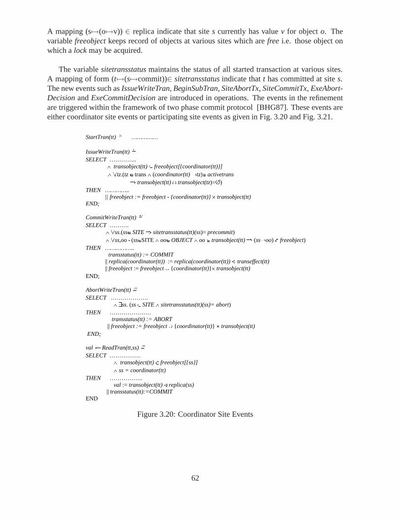
A mapping (s�→(o�→v)) ∈ replica indicate that site s currently has value v for object o. Thevariable freeobject keeps record of objects at various sites which are free i.e. those object onwhich a lock may be acquired.
The variable sitetransstatus maintains the status of all started transaction at various sites.A mapping of form (t �→(s�→commit))∈ sitetransstatus indicate that t has committed at site s.The new events such as IssueWriteTran, BeginSubTran, SiteAbortTx, SiteCommitTx, ExeAbort-Decision and ExeCommitDecision are introduced in operations. The events in the refinementare triggered within the framework of two phase commit protocol [BHG87]. These events areeither coordinator site events or participating site events as given in Fig. 3.20 and Fig. 3.21.
StartTran(tt) Å …………… IssueWriteTran(tt) Å SELECT ………….. ¶ transobject(tt) z freeobject[{coordinator(tt)}] ¶ Atz.(tz e trans ¶ (coordinator(tt) åtz)e activetrans fi transobject(tt) I transobject(tz)=0) THEN ………….. || freeobject := freeobject - {coordinator(tt)} * transobject(tt) END; CommitWriteTran(tt) Å SELECT ………. ¶ Ass.(sse SITE fi sitetransstatus(tt)(ss)= precommit) ¶ Ass,oo • (sseSITE ¶ ooe OBJECT ¶ oo e transobject(tt) fi (ssåoo) ‰ freeobject) THEN …………….. transstatus(tt) := COMMIT || replica(coordinator(tt)) := replica(coordinator(tt)) + transeffect(tt) || freeobject := freeobject U {coordinator(tt)}* transobject(tt) END; AbortWriteTran(tt) Å SELECT ………………. ¶ Ess. (ss e SITE ¶ sitetransstatus(tt)(ss)= abort) THEN ………………… transstatus(tt) := ABORT || freeobject := freeobject U {coordinator(tt)} * transobject(tt) END; val a ReadTran(tt,ss) Å SELECT ……………. ¶ transobject(tt) e freeobject[{ss}] ¶ ss = coordinator(tt) THEN …………….. val := transobject(tt) r replica(ss) || transstatus(tt):=COMMIT END
Figure 3.20: Coordinator Site Events
62

Coordinator Site Events
The coordinator site events are given in Fig. 3.20. The submission of a fresh transaction ttis modelled by the event StartTran(tt). The site of submission of transaction is assigned asa coordinator site of that transaction. The event IssueWriteTran(tt) models the issuing of anupdate transaction at the coordinator. The guard of IssueWriteTran(tt) ensures that a transactiontt is issued by the coordinator when all active transactions running at the coordinator site of ttare not in conflict with tt.
The CommitWriteTran(tt) models the commit event of an update transaction. An updatetransaction tt globally commits only if all participating sites are ready to commit it, i.e., ithas status pre-commit at all sites. As a consequence of the occurrence of the commit event atthe coordinator, the replica maintained at the coordinator site is updated with the transactioneffects. The data objects held for transaction tt are declared free and the status of the transactionat the coordinator site is set to commit. The AbortWriteTran(tt) event ensures that an updatewill abort if it has aborted at some participating site. A pending read-only transaction tt returnsthe value of objects in the set transobject(tt) from the replica at its coordinator.
Participating Site Events
The participating site event are given in Fig. 3.21. The BeginSubTran(tt,ss) event models start-ing a subtransaction of tt at participating site ss. The guard of BeginSubTran(tt) ensures that asub transaction of tt is started at participating site ss when all transactions tz running at ss are notin conflict with tt. A participating site ss can independently decide to either pre-commit or aborta subtransaction. The events SiteCommitTx(tt,ss) and SiteAbortTx(tt,ss), model pre-committingor aborting a subtransaction of tt at ss.
The event of ExeCommitDecision(tt,ss) and ExeAbortDecision(tt,ss) model commit andabort of tt at participating site ss once the global abort or commit decision has been takenby the coordinating site. In the case of global commit, each site updates its replica separately.
It can be noticed that in the abstract model, an update transaction modifies the abstract one-copy database through a single atomic event. In the refinement, an update transaction consistsof a collection of interleaved events updating each replica separately. This is achieved by re-placing abstract variable database by the concrete variable replica. The transaction mechanismon the replicated database is designed to provide the illusion of atomic update of a one copydatabase.
3.8.4 Gluing Invariants
The development methodology supported in B Method is stepwise refinement. This is doneby specifying an abstract model and successively transform it to more detailed refinements.For verification of distributed algorithms, rigorous description of problem may be given inabstract model and solution may be introduced in detailed specifications in refinement steps.The properties on the system are defined through invariants. In the refinement checking, B toolgenerate proof obligation which needs to be discharged to show that a refinement is valid. TheInvariant which holds on abstract model also holds on the refinement.
63
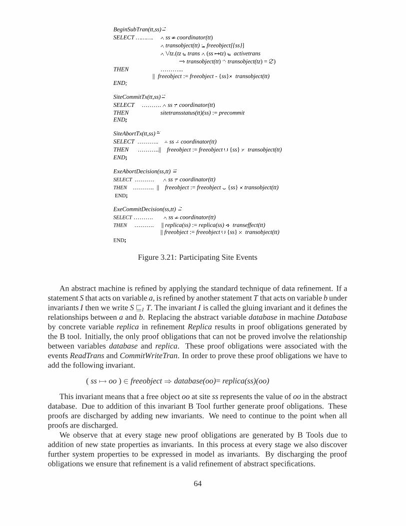
BeginSubTran(tt,ss)Å SELECT ………. ¶ ss Î coordinator(tt) ¶ transobject(tt) z freeobject[{ss}] ¶ Atz.(tz e trans ¶ (ss åtz) e activetrans fi transobject(tt) I transobject(tz) = 0) THEN ………... || freeobject := freeobject - {ss}* transobject(tt) END; SiteCommitTx(tt,ss)Å SELECT ………. ¶ ss Î coordinator(tt) THEN sitetransstatus(tt)(ss) := precommit END; SiteAbortTx(tt,ss)Å SELECT ……….. ¶ ss Î coordinator(tt) THEN ………..|| freeobject := freeobject U {ss} * transobject(tt) END; ExeAbortDecision(ss,tt) Å SELECT ………. ¶ ss Î coordinator(tt) THEN ……….. || freeobject := freeobject U {ss} * transobject(tt) END; ExeCommitDecision(ss,tt) Å SELECT ………. ¶ ss Î coordinator(tt) THEN ………. || replica(ss) := replica(ss) + transeffect(tt) || freeobject := freeobject U {ss} * transobject(tt) END;
Figure 3.21: Participating Site Events
An abstract machine is refined by applying the standard technique of data refinement. If astatement S that acts on variable a, is refined by another statement T that acts on variable b underinvariants I then we write S�I T. The invariant I is called the gluing invariant and it defines therelationships between a and b. Replacing the abstract variable database in machine Databaseby concrete variable replica in refinement Replica results in proof obligations generated bythe B tool. Initially, the only proof obligations that can not be proved involve the relationshipbetween variables database and replica. These proof obligations were associated with theevents ReadTrans and CommitWriteTran. In order to prove these proof obligations we have toadd the following invariant.
( ss �→ oo ) ∈ freeobject⇒ database(oo)= replica(ss)(oo)
This invariant means that a free object oo at site ss represents the value of oo in the abstractdatabase. Due to addition of this invariant B Tool further generate proof obligations. Theseproofs are discharged by adding new invariants. We need to continue to the point when allproofs are discharged.
We observe that at every stage new proof obligations are generated by B Tools due toaddition of new state properties as invariants. In this process at every stage we also discoverfurther system properties to be expressed in model as invariants. By discharging the proofobligations we ensure that refinement is a valid refinement of abstract specifications.
64

3.8.5 Conclusions
In this section we outlined a formal approach to modelling and analyzing distributed system bymeans of abstraction and refinement. We have presented a case study on distributed transac-tion mechanism for replicated database. In the abstract model, an update transaction modifiesthe abstract one copy database through a single atomic event. In the refinement, an updatetransaction consists of a collection of interleaved events updating each replica separately. Thetransaction mechanism on the replicated database is designed to provide the illusion of atomicupdate of a one copy database.
The system devolvement approach considered is based on Event B which facilitates the in-cremental development of distributed system. The B tool generates the proof obligations forrefinement and consistency checking. The majority of proofs were discharged using the auto-matic prover of the tool, however some complex proof requires use of the interactive prover.These proofs helps to understand the complexity of problem and the correctness of the solu-tions. Our experience with this case study strengthens our believe that abstraction and refine-ment are valuable technique for modelling complex distributed system.
3.9 Verification of Coordinated Exception Handling
Usually, a large part of the system code is devoted to error detection and handling [Cri89,WN04]. However, since developers tend to focus on the normal activity of applications andonly deal with the code responsible for error detection and handling at the implementationphase, this part of the code is usually the least understood, tested, and documented [Cri89].In order to achieve the desired levels of reliability, mechanisms for detecting and handlingerrors should be developed systematically from the early phases of development [RdFC05].Ideally, the construction of system fault tolerance mechanisms should follow a rigorous orformal development methodology [BFG02].
Error recovery in concurrent and distributed systems is known to be complicated by variousfactors, such as high cost of reaching an agreement, absence of a global view on the systemstate, multiple concurrent errors, etc. These systems require special error recovery mechanismsthat suit their main characteristics. The Coordinated Atomic (CA) Actions concept [XRR+95]results from combining distributed transactions and atomic actions for the construction of re-liable distributed systems that use competitive and cooperative concurrency. Atomic actionscontrol cooperative concurrency and implement coordinated exception handling [CR86] whilstdistributed transactions maintain the consistency of the resources shared by competing actions.CA actions function as exception handling contexts for cooperative systems so that any excep-tion raised in an action is handled in a coordinated manner by all action participants.
In order for CA actions to be applicable for the construction of complex, real-world sys-tems with strict dependability requirements, software development based on CA actions has tobe supported by rigorous models, techniques, and tools. Several approaches have been pro-posed for formalizing the CA action concept with the intention either to give a more completeand rigorous description of the concept [VG00] or to verify systems designed using CA ac-tions [XRR+02]. However, an important aspect of CA actions that has not been addressed byexisting work is the modelling and verification of the coordinated exception handling. This issurprising, since exception handling complements other techniques for improving reliability,
65

such as atomic transactions, and promotes the implementation of specialized and sophisticatederror recovery measures. Moreover, in distributed applications where a rollback is not possible,such as those that interact with the environment, exception handling may be the only choiceavailable.
In this work, we examine the problem of specifying CA action-based designs in a way thatallows us to verify automatically if these designs exhibit certain properties of interest regardingcoordinated exception handling. Moreover, since coordinated exception handling is stronglyrelated with action structuring, it is also necessary to model how CA actions are nested andcomposed [RPZ03] to define multiple exception handling contexts. We present an approach tomodeling CA action-based designs that makes it possible to verify these designs automaticallyusing a constraint solver. The main component of the proposed approach is a formal modelof CA actions that specifies the structuring of a system in terms of actions, as well as infor-mation relative to exception flow amongst these actions. This model can be directly specifiedusing well-known specification languages, like B [Abr96] and Alloy [Jac02], and verified au-tomatically using the tool sets associated with these languages. This work resulted in a paperpresented at this year’s ACM Symposium on Applied Computing [CFRR06]. A more detaileddescription of the proposed approach is available as a technical report [CRR05].
In the proposed approach, developers start by performing traditional activities of a softwaredevelopment process, namely, analysis and architectural design of the system, assuming thatthe system is concurrent and cooperative. At the same time, they define the scenarios in whichthe system may fail (fault model), what exceptions correspond to each type of error, and whereand how the exceptions are handled (exceptional activity). The specification of the system’sfault model and exceptional activity can be conducted as prescribed by some works in theliterature [RdFC05]. The result of these activities is a CA action-based design of the systemthat includes a description of the exceptions that can be raised in each CA action and howthey are handled. This design is usually described in a modeling language for CA actions(or simply modeling language), for example, the Coala [VG00] formal language, or the FTT-UML [GCR04] profile for the UML.
To verify the CA action-based design, it is necessary to translate it to a formal languagewith adequate support for automated verification (verification language). Examples of suchlanguages are B [Abr96] and Alloy [Jac02]. If the modeling language has a well-defined se-mantics, like Coala, this translation can be completely automated by a tool. The translation canalso be automated for informal notations, like UML profiles, but only partially. Usually, somemanual intervention is required to resolve ambiguities. Developers used to formal methods canwrite the system descriptions directly in the verification language. The choice of using one ortwo specification languages is based solely on usability issues.
The formal specification produced by translating the CA action-based design to the verifi-cation language must adhere to a generic CA actions meta-model specifying the elements ofCA actions and how they relate (hereafter called generic CA actions model). This meta-modelsupports a static description of the CA action-based design that ignores temporal informa-tion. The elements of the generic CA actions model are ACTION, ROLE, PARTICIPANT, andROOT EXCEPTION. They are the main concepts used in the definition of CA actions. Someof them, like ACTION and ROLE, include additional information represented through relationsand functions. For example, the set of roles of an action is defined by the ROLES relation,which associates actions to their respective roles. Both the formal specification and the genericCA actions model are described in the verification language. Up to now, we specified generic
66

CA actions models using B and Alloy as verification languages [CRR05]. Developers can useeither of them to formalize CA action-based designs.
A system is verified by providing its formal specification as input to a constraint solver forthe verification language, together with the properties to be verified. The properties of interestthat a system must satisfy are split in three categories: basic, desired, and application-specific.Basic properties define the well-formedness rules of the model, the characteristics of valid CAactions. They specify the coordinated exception handling mechanism and how actions are orga-nized. Desired properties are general properties that are usually considered beneficial, althoughthey are not part of the basic mechanism of CA actions. In general, they assume that the basicproperties hold. Application-specific properties are rules regarding the flow of exceptions in aspecific CA action-based application. Examples of basic (BP) and desired (DP) properties arepresented below, stated informally. The paper describing this approach [CFRR06] includes anexample of application-specific property.
BP1. If a participant performs a role in a nested action, it must also perform some role in thecontaining action.
BP2. No cycles in action nesting.
BP3. The exception resolution mechanism of an action resolves all possible combinations ofconcurrent internal exceptions, unless explicitly stated otherwise.
DP1. Top-level (not nested) CA actions have no external exceptions.
DP2. All internal exceptions of an action are handled in it.
DP3. Any role of an action has handlers for all of the action’s internal exceptions, including allresolved ones.
The snippet below presents a formal specification for properties BP1 and DP1 in B, usingthe ASCII version of the B Abstract Machine Notation [Abr96] supported by B-compliant toolssuch as ProB.
!A.((A:ACTION) =>/***** Property BP1 *****/!NA.((NA:ACTION & NA:NestedActions[{A}]) =>!NAR.((NAR:ROLE & NAR:Roles[{NA}]) =>#P.(P:PARTICIPANT & NAR:RolesPlayed[{P}]& card(RolesPlayed[{P}] /\ Roles[{A}]) > 0))
)&/***** Property DP1 *****/(not(#TLA.(TLA:ACTION & A:NestedActions[{TLA}])) => External[{A}] = {})
We used the Alloy Analyzer [Jac04] and ProB [LB04] constraint solvers to verify formalspecifications in Alloy and B, respectively. If any of the properties of interest does not hold,the constraint solver produces a counterexample. Both constraint solvers, besides generating acounterexample, include a graphic visualizer that provides additional help in the identificationof the problem.
The usefulness of the proposed approach was demonstrated by a case study. The target ofthe case study was the Fault-Tolerant Insulin Pump Therapy [CGP05], a control system withstrict reliability requirements for treating patients with diabetes. A detailed description of this
67

system, including a CA action-based design, is available elsewhere [CGP05]. The proposedapproach helped us to uncover some problems in the original, informal design of the system.The first one was an implicit assumption that we discovered while manually translating theUML description of the system to B, according to the proposed approach. The second problemwas pointed out by ProB when we tried to verify the formal specification of the system. Theproblems we found were directly related to the use of coordinated exception handling. In otherformal models for specifying CA actions, it would be harder to spot problems like the ones wefound because they focus on different aspects of CA action-based systems, such as temporalordering of events [XRR+02] and dynamic CA action structuring [TLIR04].
3.10 On Specification and Verification of Location-based FaultTolerant Mobile Systems
This work investigates context aware location-based mobile systems. In particular, we are in-terested how their behaviour, including fault tolerant aspects, could be captured using a formalsemantics, which would then be suitable for analysis and verification. We propose a new for-malism and middleware, called CAMA, which provides a rich environment to test our approach.The approach itself aims at giving CAMA a formal concurrency semantics in terms of a suitableprocess algebra, and then applying efficient model checking techniques to the resulting processexpressions in a way which alleviates the state space explosion. The model checking techniqueadopted in our work is partial order model checking based on Petri net unfoldings, and we usea semantics preserving translation from the process terms used in the modelling of CAMA to asuitable class of high-level Petri nets.
Model-checking carries out the verification of a system using a finite representation of itsstate space, and exhibits a trade-off between the compactness of this representation and timeefficiency. For example, deadlock detection is PSPACE-complete for a compact (bounded)Petri net or equivalent process algebra representation, but polynomial for state graph repre-sentation. However, the latter is often exponentially larger, causing the state space explosionproblem [Val98].
Mobile systems are highly concurrent causing a state space explosion when applying model-checking techniques. One should therefore use approach which alleviates this problem. In ourcase, we focus on an approach based on partial order semantics of concurrency and the cor-responding Petri net unfoldings [McM92]. A finite and complete unfolding prefix of a Petrinet is a finite acyclic net which implicitly represents all the reachable states of the original net.Efficient algorithms exist for building such prefixes [Kho03], and complete prefixes are oftenexponentially smaller than the corresponding state graphs, especially for highly concurrent sys-tems, because they represent concurrency directly rather than by multidimensional “diamonds”as it is done in state graphs. Referring to the mobility model by CAMA, our approach is par-ticularly suitable for verification of reachability-like (or state) properties, such as:
• The system never deadlocks, though it may terminate in a pre-defined set of successfultermination states.
• Security properties, i.e., all sub-scope participants are participants of the containingscope.
68

• Proper using of the scoping mechanism, for example: a scope owner does not attemptto leave without removing the scope; agents do not leave or delete a scope when otheragents expect some input from the scope; and the owner of a scope does not delete itwhile there are still active agents in the scope.
• Proper use of cooperative recovery: all scope exceptions must be handled when a scopecompletes; all scope participants eventually complete exception handling; and no excep-tions are raised in a scope after an agent leaves it.
• Application-specific invariants. (Note that the negation of an invariant is a state property,i.e., the invariant holds iff there is no reachable state of the system where it is violated.)
To our knowledge, this is the first attempt to develop unfolding based model checking techniquefor mobile systems, and consequently it was clear right from the start that we would need tomake several decisions of both theoretical and implementation nature.
3.10.1 Our approach
The first problem we had to address was the choice of formal model for capturing the propertiesand behaviour of mobile systems. A decision was made to focus initially on existing formalismsfor mobility with the view that the expected model checkers would then be easily adaptable tothe context of CAMA. We decided to investigate two process algebras for mobility, viz. π-calculus [MPW92, Par01] and KLAIM [BBN+03, NFP98]. They represent both synchronousand asynchronous models of distributed systems computation, and so we expected that theywould cover a full range of issues relating to the mobility case study. π-calculus allows, inparticular, to express dynamic change in the process ability to communicate with the externalenvironment, by passing new channels through interactions on previously known channels. Italso provides means to express and reason about a variety of security related aspects. Thechoice of the second model was influenced by our work in other parts of the Ambient Campuscase study. KLAIM, in particular, supports explicit localities which are first-class data thatcan be manipulated by active processes, and coordination primitives for controlled interactionsamong processes located at network’s localities.
We the set out to develop semantics-preserving translations (in the sense of provably gen-erating strongly equivalent labelled transition systems) of both the π-calculus and KLAIM intosuitable classes of high-level Petri nets. Our choice for the latter was a modular model of high-level Petri nets, resulting in compositional translation of process expression terms. The work ontranslating π-calculus has been carried out throughout the duration of RODIN, and resulted intwo translations: one for finite π-calculus terms [DKK06b], and recently for general recursiveexpressions [DKK06c]. The translation of KLAIM was based on some key ideas of our workon the π-calculus, and was first reported in [DKK06a].
3.10.2 Model-checking mobile systems
In [DKK06b] we proposed a translation of a π-calculus term P results in a p-net (a kind of high-level Petri net) with a very close behavioural relationship with the original process expression.More precisely, [DKK06b] showed that the labelled transition system of P is strongly bisimularto the labelled transition system of the p-net PN(P).
69

The theoretical translation described in [DKK06b] is not directly implementable (due to theinfinite number of tokens in a special tag place employed by the translation), and in our imple-mentation oriented work we set out to modify it in such a way that it could be model-checkedby existing tools. Moreover, the specific model-checking technique we decided to use was rightfrom the beginning the unfolding-based verification of Petri nets, which already proved to beefficient in dealing with, e.g., digital asynchronous systems and distributed programs [Kho03].
There are several variations of the unfolding-based model-checking technique, includingunfolders and property verifiers. The way p-nets are defined suggests that one should employa variant which is capable to deal efficiently with coloured tokens and high-level arc annota-tions. In particular, one should avoid the expansion of the high-level Petri net to its low-levelrepresentation and unfolding the latter, since such an approach may yield a huge intermediatelow-level net, rendering the whole attempt practically useless (see [KK03] for a thorough dis-cussion of this issue). We therefore decided to use the PUNF model-checker (complementedby the MPSAT property verifier based on a SAT-solver), which directly applies unfolding tohigh-level nets without expanding them to low-level nets, as described in [KK03]. Having de-cided on the particular unfolding approach, we then had to address a number of implementationissues, as described in the rest of this paper.
3.10.3 Key implementation issues
A basic problem we faced right from the outset was that p-nets are not compatible with the inputrequired by the unfolder, in that PUNF requires as input a high-level net which: (i) is strictlysafe in the sense that no place can ever hold more than one coloured token; and (ii) does notinclude any read-arcs. Another, even more fundamental, issue is that the p-net resulting fromthe translation will in all but the simplest cases have infinite state space. The reason is that theset of potentially known (or new) channel names is countably infinite, and so any input prefixwhich receives a name from the environment will necessarily give rise to infinite branching. Asa result, a naıve state space exploration through exhaustive enumeration is bound to fail. Theway in which addressed these problems is outlined below.
Infinity of new channels. We are primarily interested in checking state properties of mobilesystems expressed using π-calculus expressions. For this reason, the main property of channelswe are interested in is whether a channel which has been received from the environment isbrand new (i.e., fresh) or the same as one of the already known channels. As far as sending tothe outside of channels previously restricted is concerned, they are always brand new (fresh),i.e., different from those already known. As the precise identity of a channels which has justbecome known is irrelevant for our purposes, we proceed as follows: (i) if a restricted channelβ is sent outside it becomes known simply as β; and (ii) if input into a channel α happened andthe inserted channel is a fresh channel, its identity is set to α, otherwise it is one of the existingknown channels. In this way, the number of known channels other than those present initiallyis bounded by the total number of action names appearing in a π-calculus term. The resultingmodel can therefore be made bounded and then model-checked. It is worth observing that thistreatment of newly known channels is a kind of symmetry reduction employed at the level ofsystem modelling.
70

Read arcs. A specific feature of p-nets is that they use read arcs which test for the presenceof tokens without consuming them. We use the standard simulation of a read arc using twodirected arcs pointing in the opposite directions. Intuitively, this replaces a non-destructive readoperation by a destructive one, followed by a re-write. One can observe that this transformationpreserves the interleaving semantics of the net.
Non-safeness. Almost all of the places in p-nets resulting from translation are strictly safe,and so conform to the input required by PUNF. The tag-place, on the other hand, is neversafe (actually, in the theoretical translation its marking is always infinite). However, with thedecisions about the modelling of known channels made above, we can simulate the working ofthe tag-place by introducing a status places for each action of a process term. The status placeholds always one token, 0 or 1 (initially 0), and is suitably updated during the execution of thep-net.
Partial transition expansion. An immediate side-effect of replacing the tag-place by a finiteset of status places is that each of the transitions used in the original translation accessing thetag-place needs to be replaced by a set of transition jointly simulating the effect of a singletransition in the original translation (note that transition modelling internal communication donot need to be modified). The overall effect was that the number of transition increased buttheir arc annotations became simpler.
3.10.4 Experimental results
In our experiments described in [KKN06], we used simple ‘classroom’ scenarios inspired bythe Ambient Campus case study. A typical π-calculus-like example has the following form:
NESS(n)df= (νh)(νh1) . . . (νhn) (T | S1 | . . . | Sn)
where T represents a ‘teacher’ process, and each Si a ‘student’ process. Their respective defi-nitions are as follows (note that input prefixes are denoted as a?b and the output ones as a!b):
Tdf= a?ness . (h1!ness . h1?x1 . 0 | · · · | hn!ness . hn?xn . 0)
Sidf= hi?addri . (h!hi . hi!done . 0
+h?anotheri . addri!hi . addri!anotheri . hi!done . 0)
The idea is that the teacher first receives from the school electronic submission system2 a chan-nel ness using which the students are supposed to submit their work for assessment. Theteacher passes this channel to all the students (using n parallel sub-processes), and (also in par-allel) then waits for the confirmation that the students have finished working on the assignmentbefore terminating. A student’s behaviour is somewhat more complicated. After receivingthe ness channel, students are supposed to organise themselves to work on the assignment inpairs and, after finishing, exactly one of them sends to the support system (using the previouslyacquired ness channel) two channels which give access to their completed joint work. Thestudents finally notify the teacher about the completion of their work. The property to verify
2Called NESS in Newcastle.
71
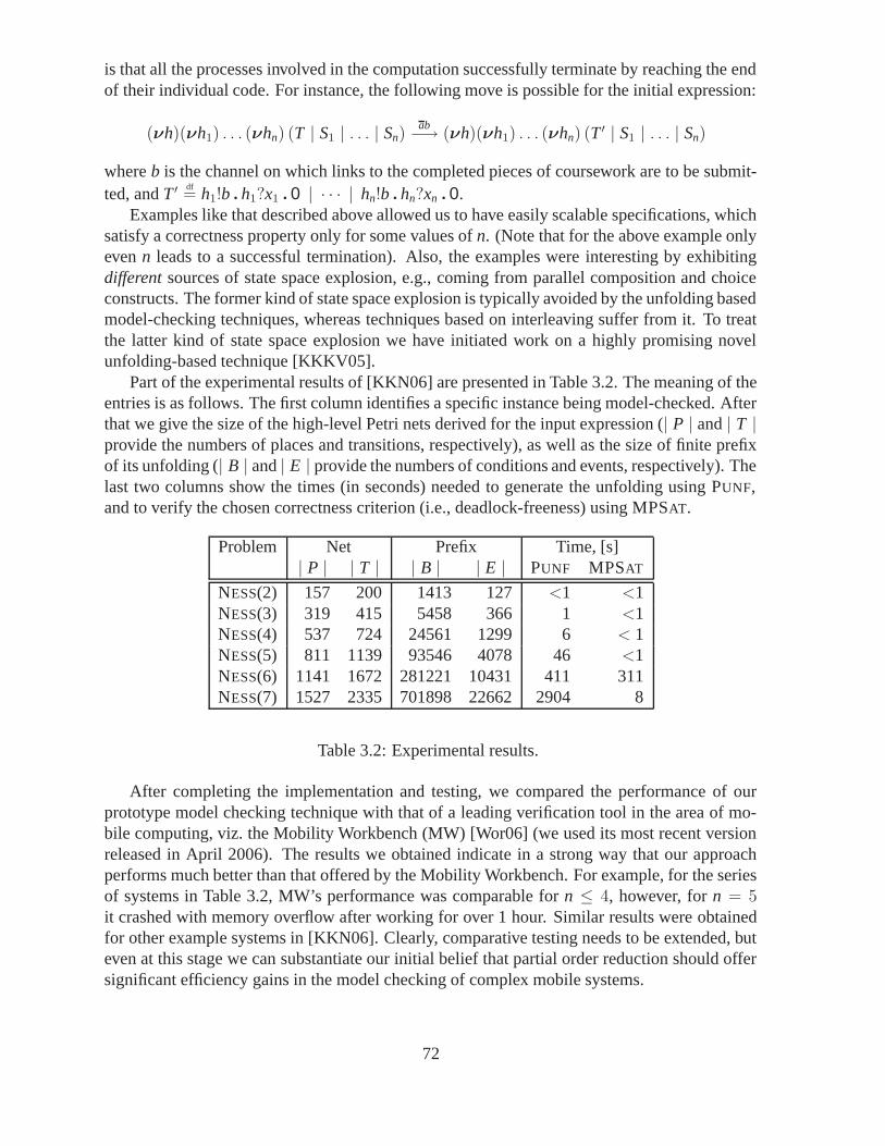
is that all the processes involved in the computation successfully terminate by reaching the endof their individual code. For instance, the following move is possible for the initial expression:
(νh)(νh1) . . . (νhn) (T | S1 | . . . | Sn)ab−→ (νh)(νh1) . . . (νhn) (T ′ | S1 | . . . | Sn)
where b is the channel on which links to the completed pieces of coursework are to be submit-ted, and T ′ df
= h1!b . h1?x1 . 0 | · · · | hn!b . hn?xn . 0.Examples like that described above allowed us to have easily scalable specifications, which
satisfy a correctness property only for some values of n. (Note that for the above example onlyeven n leads to a successful termination). Also, the examples were interesting by exhibitingdifferent sources of state space explosion, e.g., coming from parallel composition and choiceconstructs. The former kind of state space explosion is typically avoided by the unfolding basedmodel-checking techniques, whereas techniques based on interleaving suffer from it. To treatthe latter kind of state space explosion we have initiated work on a highly promising novelunfolding-based technique [KKKV05].
Part of the experimental results of [KKN06] are presented in Table 3.2. The meaning of theentries is as follows. The first column identifies a specific instance being model-checked. Afterthat we give the size of the high-level Petri nets derived for the input expression (| P | and | T |provide the numbers of places and transitions, respectively), as well as the size of finite prefixof its unfolding (| B | and | E | provide the numbers of conditions and events, respectively). Thelast two columns show the times (in seconds) needed to generate the unfolding using PUNF,and to verify the chosen correctness criterion (i.e., deadlock-freeness) using MPSAT.
Problem Net Prefix Time, [s]| P | | T | | B | | E | PUNF MPSAT
NESS(2) 157 200 1413 127 <1 <1NESS(3) 319 415 5458 366 1 <1NESS(4) 537 724 24561 1299 6 < 1NESS(5) 811 1139 93546 4078 46 <1NESS(6) 1141 1672 281221 10431 411 311NESS(7) 1527 2335 701898 22662 2904 8
Table 3.2: Experimental results.
After completing the implementation and testing, we compared the performance of ourprototype model checking technique with that of a leading verification tool in the area of mo-bile computing, viz. the Mobility Workbench (MW) [Wor06] (we used its most recent versionreleased in April 2006). The results we obtained indicate in a strong way that our approachperforms much better than that offered by the Mobility Workbench. For example, for the seriesof systems in Table 3.2, MW’s performance was comparable for n ≤ 4, however, for n = 5it crashed with memory overflow after working for over 1 hour. Similar results were obtainedfor other example systems in [KKN06]. Clearly, comparative testing needs to be extended, buteven at this stage we can substantiate our initial belief that partial order reduction should offersignificant efficiency gains in the model checking of complex mobile systems.
72
Further experiments During the series of experiments we conducted, a closer analysis offiring sequences leading to deadlocks detected what might be considered as a ‘security breach’.More precisely, the specification allows the whole protocol to terminate successfully in such away that the students inform the environment (rather than the teacher), and the teacher receivesthe completion messages from the environment (rather than from the students). Intuitively,this means that the environment acts as an ‘intruder in the middle’. Moreover, on the verifi-cation side, the possibility of ‘too many’ communications with the environment should alsoincrease the size of the resulting unfolding. One would therefore expect that the situation be-comes different if most of the communication is done within the system’s processes. To testthis hypothesis, and to address the security issue described above, we re-designed the originalspecification, in the following way:
SNESS(n)df= (νh)(νh1) · · · (νhn)(νhres) (T ′′ | S′′
1 | · · · | S′′n)
where:
T ′′ df= a?ness . (h1!ness . h1!hres.hres?x1 . 0
| · · · | hn!ness . hn!hres . hres?xn.0)
S′′i
df= hi?addri . hi?reporti .
(h!hi . reporti!done . 0+h?anotheri . addri!hi . addri!anotheri . reporti!done . 0)
Intuitively, SNESS(n) uses a new secret channel hres to ensure that the communication betweenthe students and the teacher about the completion of coursework does not leak outside thesystem. The results confirmed our initial hypothesis.
Finally, we investigated the effect of reducing the state explosion due the protocol for pair-ing the students. We therefore model-checked the system assuming that the students know inadvance what the pairing is, and who is to communicate with the environment. This, of course,was only possible if n is even. The results indicated that the unfolding copes very well with thestate space explosion which is due to concurrency present in the system specification.
3.10.5 Conclusions
The results of this work, reported in [KKN06] as well as in the paper to be published in theREFT book[IKKR05] directly contribute to T2.1, T2.3 and T2.4 of WP2. They indicate thatmodel-checking based on Petri net unfoldings can be a successful technique to deal with dis-tributed systems with mobility. We can also identify at least three challenging areas of fu-ture work leading to potentially significant improvements in efficiency and applicability of thepresent approach:
• To develop an unfolding technique dealing with the read arcs in a direct way, rather thansimulating them using pairs of directed arcs. A significant step forward towards such atechnique has been made in [KK06], where foundations for the unfolding of inhibitorarcs (which are complementary to read arcs) have been developed.
• To introduce a restricted form of π-calculus recursion (or iteration) still allowing one touse model-checking. This work has already strong theoretical underpinnings contained
73

in [DKK06c], and we are now working on suitable implementation of a restricted versionof the solution presented there.
• To deal with the state space explosion problem caused by aspects other than a highlevel of concurrency; there are strong indications that the recently proposed merged pro-cesses [KKKV05] could offer an effective solution.
74

3.11 Bits ’n Pieces
Datamation used to have a section of short news items: this section collects together notes onsome evolving pieces of work.
Design patterns During the second year we have been working on developing a set of designpatterns and the decomposition method to be applied in rigorous development of the large scaleopen agent systems. This work is reported in the second year deliverable D18 (§6) and inmore details in [ILRT06]. Four patterns: the specification pattern, the decoupling pattern, therefinement pattern and the decomposition pattern have been proposed and applied in our workon the Ambient Campus Case Study. Application of these patterns allows developers to ensureagent interoperability, decentralised development and code reuse.
Modelling systems based on languages Part of the work being done in the Ambient Campuscase study (CS5) involves the use of the Linda and Publish/Subscribe coordination mechanism.However, in the development of our scenario, we have found it necessary to use a languuagewhich combines the features of both Linda and Publish/Subscribe. As the two systems are notmutually descriptive, it is not possible to properly emulate one in the other.
To this end, a framework was developed around a coordination language which providesthe features of both Linda and Publish/Subscribe and this language was defined by way of anEvent-B model. However, this resulted in an ad hoc semantics that was ambiguous, difficult tounderstand and difficult to extend safely.
The coordination language has since been redefined in terms of a structural operationalsemantics (SOS). In doing so, we were forced to confront –and resolve– the ambiguities in thelanguage, including some that we had not been aware of initially.
Despite the different natures and pragmatic intents of Event-B and SOS models, there areinteresting correspondences in their notational styles. This correspondence not only makes thetask of feeding the work done on the SOS model back into the Event-B model easier, but it alsoallows a high degree of confidence that the two models represent the same system.
The importance of a clean, unambiguous language semantics cannot be overstated whenattempting to build a model of a system based on that language. The correspondence betweenthe two methods suggest there are interesting formal links to be pursued, though even theinformal connection we have explored thus far has been very useful. Our work will appear in aforthcoming Technical Report at Newcastle University.
SOS Joey Coleman is presenting a paper at the FM-Ed-06 meeting in Canada.
Relevant publications not cited elsewhere in this report Readers might be interested in [HJR04,JR05, Ran00, JOW06, Jon05a, CJO+05, BGJ06, WV01, Jon81, dRE99, Owi75, OG76, Jon83a,Jon83b, Jon96, Stø90, Col94, Xu92, Bue00, Din00, BS01, dR01, Plo81, Plo04b, Plo04a, Jon96,Bur04, Nip04, CM92].
75

Chapter 4
The way ahead
This “Month 24” document reports on considerable progress on methodological issues facingRodin and its eventual users. There still remains much work to be done before we can claim tohave a formal development method for fault-tolerant systems.
We see the main challenge for the last year as producing a coherent final document whichsummarises what has been achieved. This task is made possible because of the significant bookbeing produced by Jean-Raymond Abrial. The WP2 final report will both build on this andconfine itself to material which does not fit into the Event-B framework.
We have always made clear that our prime deliverable on the tools front will be coherentsupport for Event B. We will incorporate as many ideas as possible into this framework. Fur-thermore, the “plug-in” idea offers us a way of providing support for other concepts. To givejust one example, the “UML to B” concept offers a way of seducing a community which is notalready using formal methods towards the more formal Rodin tools. There are however otherideas which would require separate support at the formal level. An example here is the use ofrely/guarantee style specifications.
We will obviously want to report on other methodoloogies that can help the user developdependable complex systems. Appendix A sets out a possible structure for the final deliverableon Methodology: we should be delighted to discuss this with our project officer and the chosenreviewers. It is worth stating now that we think it would be counter productive to attempt a“catalogue of everything” in the final report: we will maximise coverage but only in so far aswe can offer the reader a coherent story.
76

Bibliography
[Abr96] J.-R. Abrial. The B-Book: Assigning programs to meanings. Cambridge Univer-sity Press, 1996.
[AC03] Jean-Raymond Abrial and Dominique Cansell. Click’n prove: Interactive proofswithin set theory. In TPHOLs 2003, pages 1–24, 2003.
[ACM03] Jean-Raymond Abrial, Dominique Cansell, and Dominique Mery. A mechan-ically proved and incremental development of ieee 1394 tree identify protocol.Formal Asp. Comput., 14(3):215–227, 2003.
[AIR06] B. Arief, A. Iliasov, and A. Romanovsky. On Using the CAMA Framework forDeveloping Open Mobile Fault Tolerant Agent Systems. University of Newcastle.Technical report, University of Newcastle, 2006.
[BBN+03] L. Bettini, V. Bono, R. De Nicola, G. L. Ferrari, D. Gorla, M. Loreti, E. Moggi,R. Pugliese, E. Tuosto, and B. Venneri. The klaim project: Theory and practice.In Global Computing, volume LNCS 2874 of LNCS, pages 88–150. Springer-Verlag, 2003.
[BFG02] Cinzia Bernardeschi, Alessandro Fantechi, and Stefania Gnesi. Model checkingfault tolerant systems. Software Testing, Verification, and Reliability, 12:251–275,December 2002.
[BGJ06] D. Besnard, C. Gacek, and C. B. Jones, editors. Structure for Dependability:Computer-Based Systems from an Interdisciplinary Perspective. Springer, 2006.ISBN 1-84628-110-5.
[BHG87] Philip A. Bernstein, Vassos Hadzilacos, and Nathan Goodman. Concurrency Con-trol and Recovery in Database Systems. Addison-Wesley, 1987.
[BK85] J.A. Bergstra and J.W. Klop. Algebra of communicating processes with abstrac-tion. Theoret. Comp. Sci., 37:77–121, 1985.
[BKP04] J. Burton, M. Koutny, and G. Pappalardo. Implementing Communicating Pro-cesses in the Event of Interface Difference. Fundamenta Informaticae, 59:1–37,2004.
[BKPPK02] J. Burton, M. Koutny, G. Pappalardo, and M. Pietkiewicz-Koutny. Composi-tional Development in the Event of Interface Difference. In P.Ezhilchelvan and
77

A.Romanovsky, editors, Concurrency in Dependable Computing, pages 479–543.Kluwer Academic Publishers, 2002.
[BKS83] R.J.R. Back and R. Kurki-Suonio. Decentralisation of process nets with cen-tralised control. In 2nd ACM SIGACT-SIGOPS Symp. on Principles of DistributedComputing, pages 131–142, 1983.
[BLLP04] E. Bernard, B. Legeard, X. Luck, and F. Peureux. Generation of test sequencesfrom formal specifications: Gsm 11-11 standard case study. Software Practiceand Experience, 34(10):915–948, 2004.
[BS89] R.J.R. Back and K. Sere. Stepwise refinement of parallel algorithms. Sci. Comp.Prog., 13:133–180, 1989.
[BS01] Manfred Broy and Ketil Stølen. Specification and Development of InteractiveSystems. Springer-Verlag, 2001.
[Bue00] Martin Buechi. Safe Language Mechanisms for Modularization and Concur-rency. PhD thesis, Turku, 2000.
[Bur04] J. Burton. The Theory and Practice of Refinement-After-Hiding. PhD thesis,University of Newcastle upon Tyne, 2004.
[But92] M.J. Butler. A CSP Approach To Action Systems. D.Phil. Thesis, ProgrammingResearch Group, Oxford University, 1992. http://eprints.ecs.soton.ac.uk/974/.
[But96] M.J. Butler. Stepwise refinement of communicating systems. Science of Com-puter Programming, 27(2):139–173, September 1996.
[But97] M.J. Butler. An Approach to the Design of Distributed Systems with B AMN.In Jonathan P. Bowen, Michael G. Hinchey, and David Till, editors, ZUM ’97:The Z Formal Specification Notation, 10th International Conference of Z Users,Reading, UK, April 3-4, 1997, Proceedings, volume 1212 of Lecture Notes inComputer Science, pages 223–241. Springer, 1997.
[But02] Michael J. Butler. On the use of data refinement in the development of securecommunications systems. Formal Asp. Comput., 14(1):2–34, 2002.
[CFRR06] Fernando Castor Filho, Alexander Romanovsky, and Cecılia Mary F. Rubira. Ver-ification of coordinated exception handling. In Proceedings of the 21st ACM Sym-posium on Applied Computing, pages 680–685, Dijon, France, April 2006.
[CGP05] A. Capozucca, Nicolas Guelfi, and Patrizio Pelliccione. The fault-tolerant insulinpump therapy. In Proceedings of FM’2005 Workshop on Rigorous Engineeringof Fault-Tolerant Systems, pages 33–42, Newcastle upon Tyne, UK, 2005.
78

[CJ05] Joey W. Coleman and Cliff B. Jones. Examples of how to determine the specifica-tions of control systems. In M. Butler, C. Jones, A. Romanovsky, and E. Troubit-syna, editors, Proceedings of the Workshop on Rigorous Engineering of Fault-Tolerant Systems (REFT 2005), number CS-TR-915 in Technical Report Series,pages 65–73. University of Newcastle Upon Tyne, June 2005.
[CJO+05] Joey Coleman, Cliff Jones, Ian Oliver, Alexander Romanovsky, and ElenaTroubitsyna. RODIN (rigorous open development environment for complex sys-tems). In EDCC-5, Budapest, Supplementary Volume, pages 23–26, April 2005.
[CM92] J. Camilleri and T. Melham. Reasoning with inductively defined relations in theHOL theorem prover. Technical Report 265, Computer Laboratory, University ofCambridge, 1992.
[CM03] Dominique Cansell and D Merry. Foundations of the b method. Computing andInformatics., 22(1-31):2–34, 2003.
[Col94] Pierre Collette. Design of Compositional Proof Systems Based on Assumption-Commitment Specifications – Application to UNITY. PhD thesis, Louvain-la-Neuve, June 1994.
[Col06] Joey W. Coleman. Determining the specification of a control system: an illustra-tive example. In M. Butler, C. Jones, A. Romanovsky, and E. Troubitsyna, editors,Proceedings of the Workshop on Rigorous Engineering of Fault-Tolerant Systems(REFT 2005), number 4157 in Lecture Notes in Computer Science. Springer-Verlag, 2006.
[CR86] R. Campbell and B. Randell. Error recovery in asynchronous systems. IEEETransactions on Software Engineering, SE-12(8):811–826, 1986.
[Cri89] Flaviu Cristian. Exception handling. In Dependability of Resilient Computers.BSP Professional Books, 1989.
[CRR05] Fernando Castor Filho, Alexander Romanovsky, and Cecılia Mary F. Rubira. Ver-ification of coordinated exception handling. Technical Report CS-TR-927, Schoolof Computing Science, University of Newcastle upon Tyne, 2005.
[DB99] J. Derrick and E. Boiten. Testing refinements of state-based formal specifications.Software Testing, Verification and Reliability, 9:27–50, 1999.
[DF93] J. Dick and A. Faivre. Automating the generation and sequencing of test casesfrom model-based specifications. In Formal Method Europe ’03, volume 670 ofLNCS, pages 268–284. Springer Verlag, 1993.
[Din00] Jurgen Dingel. Systematic Parallel Programming. PhD thesis, Carnegie MellonUniversity, 2000.
[DJK+99] S.R. Dalal, A. Jain, N. Karunanithi, J.M. Leaton, C.M. Lott, G.C. Patton, andB.M. Horowitz. Model based testing in practice. In International Conference onSoftware Engineering, pages 285–294. ACM Press, 1999.
79

[DKK06a] R. Devillers, H. Klaudel, and M. Koutny. A Petri net semantics of a simple processalgebra for mobility. Electronic Notes in Computer Science - ENTCS, 1254, 2006.
[DKK06b] R. Devillers, H. Klaudel, and M. Koutny. Petri Net Semantics of the Finite pi-calculus Terms. Fundamenta Informaticae, 70:203–226, 2006.
[DKK06c] R. Devillers, H. Klaudel, and M. Koutny. A petri net translation of pi-calculusterms. In International Colloquium on Theoretical Aspects of Computing (sub-mitted). Springer-Verlag, 2006.
[DNFP98] R. De Nicola, G. Ferrari, and R. Pugliese. Klaim: a Kernel Language forAgents Interaction and Mobility. IEEE Transactions on Software Engineering,24(5):315–330, 1998.
[DNLM05] R. De Nicola, D. Latella, and M. Massink. Formal modeling and quantitive anal-ysis of KLAIM-based mobile systems. In Applied Computing, pages 428–435,2005.
[dR01] W. P. de Roever. Concurrency Verification: Introduction to Compositional andNoncompositional Methods. Cambridge University Press, 2001.
[dRE99] W. P. de Roever and K. Engelhardt. Data Refinement: Model-Oriented ProofMethods and Their Comparison. Cambridge University Press, 1999.
[Dun03] S. Dunne. Introducing backward refinement into b. In ZB 2003, volume 2681 ofLNCS, pages 178–196. Springer Verlag, 2003.
[EB06] Neil Evans and Michael Butler. A proposal for records in Event-B. In FormalMethods 2006, 2006.
[GCR04] Nicolas Guelfi, Guillaume Le Cousin, and Benoit Ries. Engineering of depend-able complex business processes using uml and coordinated atomic actions. InProceedings of International Workshop on Modeling Inter-Organizational Sys-tems, pages 468–482, 2004.
[GHM97] J.D. Gannon, R.G. Hamlet, and H.D. Mills. Theory of modules. IEEE Transac-tions on Software Engineering, 13(7):820–829, 1997.
[GJ79] M.R. Garey and D.S. Johnson. Computers and Intractability. W. H. Freeman andCompany, 1979.
[GR93] Jim Gray and Andreas Reuter. Transaction Processing: Concepts and Techniques.Morgan Kaufmann, 1993.
[HHS86] J. He, C.A.R. Hoare, and J.W. Sanders. Data refinement refined. In ESOP ’86,volume 213 of LNCS, pages 187–196. Springer Verlag, 1986.
[HJJ03] Ian Hayes, Michael Jackson, and Cliff Jones. Determining the specification of acontrol system from that of its environment. In Keijiro Araki, Stefani Gnesi, andDino Mandrioli, editors, FME 2003: Formal Methods, volume 2805 of LectureNotes in Computer Science, pages 154–169. Springer Verlag, 2003.
80

[HJR04] Tony Hoare, Cliff Jones, and Brian Randell. Extending the horizons ofDSE. In Grand Challenges. UKCRC, 2004. pre-publication visible athttp://www.nesc.ac.uk/esi/events.
[Hoa85] C.A.R. Hoare. Communicating Sequential Processes. Prentice–Hall, 1985.
[IKKR05] A. Iliasov, V. Khomenko, M. Koutny, and A. Romanovsky. On Specification andVerification of Location-based Fault Tolerant Mobile Systems. In REFT 2005Workshop on Rigorous Engineering of Fault-Tolerant Systems. Newcastle UponTyne, UK (http://rodin.cs.ncl.ac.uk/events.htm), June 2005.
[Ili06] A. Iliasov. Implementation of Cama Middleware. In A.Iliasov B.Arief andA.Romanovsky, editors, On Using the CAMA Framework for Developing OpenMobile Fault Tolerant Agent Systems. University of Newcastle. University ofNewcastle, 2006.
[ILRT05] A. Iliasov, L. Laibinis, A. Romanovsky, and E. Troubitsyna. Towards formaldevelopment of mobile location-based systems. In REFT’05 – Workshop on Rig-orous Engineering of Fault Tolerant Systems, July 2005.
[ILRT06] A. Iliasov, L. Laibinis, A. Romanovsky, and E. Troubitsyna. Rigorous develop-ment of fault tolerant agent systems. Technical Report TR762, Turku Centre forComputer Science, March 2006.
[IR05] A. Iliasov and A. Romanovsky. CAMA: Structured Coordination Space and Ex-ception Propagation Mechanism for Mobile Agents. Presented at ECOOP 2005Workshop on Exception Handling in Object Oriented Systems: Developing Sys-tems that Handle Exceptions. July 25, 2005. Glasgow, UK, 2005.
[ITLS06] Dubravka Ilic, Elena Troubitsyna, Linas Laibinis, and Colin Snook. Formal de-velopment of mechanisms for tolerating transient faults. Technical Report TR763,Turku Centre for Computer Science, April 2006.
[Jac02] D. Jackson. Alloy: A lightweight object modeling notation. ACM TOSEM, 11(2),April 2002.
[Jac04] D. Jackson. Alloy home page, 2004.
[JHJ06] C. B. Jones, I. J. Hayes, and M. A. Jackson. Specifying systems that connect tothe physical world. Technical Report CS-TR-964, School of Computing Science,University of Newcastle, 2006.
[Jon81] C. B. Jones. Development Methods for Computer Programs including a Notionof Interference. PhD thesis, Oxford University, June 1981.
[Jon83a] C. B. Jones. Specification and design of (parallel) programs. In Proceedings ofIFIP’83, pages 321–332. North-Holland, 1983.
[Jon83b] C. B. Jones. Tentative steps toward a development method for interfering pro-grams. ACM Transactions on Programming Languages and Systems, 5(4):596–619, 1983.
81

[Jon90a] C. B. Jones. Systematic Software Development using VDM. Prentice Hall Inter-national, second edition, 1990.
[Jon90b] C.B. Jones. Systematic Software Development using VDM (2nd Edn). PrenticeHall, 1990.
[Jon96] C. B. Jones. Accommodating interference in the formal design of concurrentobject-based programs. Formal Methods in System Design, 8(2):105–122, March1996.
[Jon03] C. B. Jones. Wanted: a compositional approach to concurrency. In AnnabelleMcIver and Carroll Morgan, editors, Programming Methodology, pages 1–15.Springer Verlag, 2003.
[Jon05a] C. B. Jones. Reasoning about the design of programs. Royal Soc, Phil Trans RSoc A, 363(1835):2395–2396, 2005.
[Jon05b] C. B. Jones. Sequencing operations and creating objects. In Proceedings TenthIEEE International Conference on Engineering of Complex Computer Systems,pages 33–36. IEEE Computer Society, 2005.
[Jon05c] Cliff Jones. The case for research into obtaining the right specification, June 2005.
[Jon05d] Cliff Jones. Determining the specification of systems involving humans, July2005.
[Jon06a] C. B. Jones. An approach to splitting atoms safely. Electronic Notes in Theo-retical Computer Science, MFPS XXI, 21st Annual Conference of MathematicalFoundations of Programming Semantics, 155:43–60, 2006.
[Jon06b] Cliff B. Jones. Reasoning about partial functions in the formal development ofprograms. In Proceedings of AVoCS’05, volume 145, pages 3–25. Elsevier, Elec-tronic Notes in Theoretical Computer Science, 2006.
[JOW06] Cliff Jones, Peter O’Hearn, and Jim Woodcock. Verified software: a grand chal-lenge. IEEE Computer, 39(4):93–95, 2006.
[JR05] Cliff Jones and Brian Randell. Dependable pervasive systems. In Trust and Crimein Information Societies, chapter 3, pages 59–90. Edward Elgar, 2005. also visibleat http://www.foresight.gov.uk.
[Kho03] V. Khomenko. Model Checking Based on Prefixes of Petri Net Unfoldings. PhDthesis, School of Computing Science, University of Newcastle upon Tyne, 2003.
[KK03] V. Khomenko and M. Koutny. Branching Processes of High-Level Petri Nets. InTACAS 2003, volume 2619 of Lecture Notes in Computer Science, pages 458–472, 2003.
[KK06] H.C.M. Kleijn and M. Koutny. Infinite Process Semantics of Inhibitor Nets. InPetri Nets and Other Models of Concurrency - ICATPN 2006, volume 4024 ofLecture Notes in Computer Science, pages 282–301, 2006.
82

[KKKV05] V. Khomenko, A. Kondratyev, M. Koutny, and V. Vogler. Merged Processes —a New Condensed Representation of Petri Net Behaviour. In CONCUR 2005,volume 3653 of Lecture Notes in Computer Science, pages 338–352, 2005.
[KKN06] V. Khomenko, M. Koutny, and A. Niaouris. Applying Petri Net Unfoldings forVerification of Mobile Systems. In Fourth International Workshop on Modellingof Objects, Components and Agents - MOCA 2006, pages 161–178. Bericht 272,Department Informatik, Universitat Hamburg, 2006.
[KMP97] M. Koutny, L. Mancini, and G. Pappalardo. Two Implementation Relations andthe Correctness of Communicated Replicated Processing. Formal Aspects ofComputing, 9:119–148, 1997.
[KPPK06] M. Koutny, G. Pappalardo, and M. Pietkiewicz-Koutny. Towards an Algebra ofAbstractions for Communicating Processes. In ACSD 2006. To be published,2006.
[Lam78] L. Lamport. The Implementation of Reliable Distributed Multiprocess Systems.Computer Networks, 2:95–114, 1978.
[LB04] M. Leuschel and Michael J. Butler. ProB: A model checker for B. In Proceedingsof FME’2003, LNCS 2805, pages 855–874. Springer-Verlag, Pisa, Italy, 2004.
[LB05] M. Leuschel and M. Butler. Automatic refinement checking for b. In ICFEM ’05,volume 3785 of LNCS, pages 345–359. Springer Verlag, 2005.
[LIM+05] Sari Leppanen, Dubravka Ilic, Qaisar Malik, Tarja Systa, and Elena Troubitsyna.Specifying UML Profile for Distributed Communicating Systems and Commu-nication Protocols. Proceedings of Workshop on Consistency in Model DrivenEngineering (C@MODE’05), November 2005.
[LTL+05] Linas Laibinis, Elena Troubitsyna, Sari Leppanen, Johan Lilius, and Qaisar Ma-lik. Formal Model-Driven Development of Communicating Systems. Proceedingsof 7th International Conference on Formal Engineering Methods (ICFEM’06),LNCS 3785, Springer, November 2005.
[LTL+06] Linas Laibinis, Elena Troubitsyna, Sari Leppanen, Johan Lilius, and Qaisar Ma-lik. Formal service-oriented development of fault tolerant communicating sys-tems. Technical Report TR764, Turku Centre for Computer Science, April 2006.
[Lyn96] Nancy A. Lynch. Distributed Algorithms. Morgan Kaufmann, 1996.
[MAV05] C. Metayer, J.-R. Abrial, and L. Voisin. Event-B language. Deliverable D7, EU-IST “RODIN” Project, 2005.
[McM92] K. L. McMillan. Using Unfoldings to Avoid State Explosion Problem in theVerification of Asynchronous Circuits. In CAV 1992, volume 663 of Lecture Notesin Computer Science, pages 164–174, 1992.
[Mil89] R. Milner. Communication and Concurrency. Prentice-Hall, 1989.
83
[Mor90] C.C. Morgan. Of wp and CSP. In W.H.J. Feijen, A.J.M. van Gasteren, D. Gries,and J. Misra, editors, Beauty is our business: a birthday salute to Edsger W.Dijkstra. Springer–Verlag, 1990.
[MPW92] R. Milner, J. Parrow, and D. Walker. A calculus of mobile processes. Informationand Computation, 100:1–77, 1992.
[NFP98] R. De Nicola, G. Ferrari, and R. Pugliese. Klaim: a kernel language for agentsinteraction and mobility. IEEE Transactions on Software Engineering, 24(5):315–330, 1998.
[Nip04] Tobias Nipkow. Jinja: Towards a comprehensive formal semantics for a java-likelanguage. Manuscript, Munich, 2004.
[OG76] S. S. Owicki and D. Gries. An axiomatic proof technique for parallel programs I.Acta Informatica, 6:319–340, 1976.
[OMG05] OMG. Unified Modeling Language (UML), Version 2.0, 2005.
[OV99] M. Tamer Ozsu and Patrick Valduriez. Principles of Distributed Database Sys-tems, Second Edition. Prentice-Hall, 1999.
[Owi75] S. Owicki. Axiomatic Proof Techniques for Parallel Programs. PhD thesis, De-partment of Computer Science, Cornell University, 1975.
[Par01] J. Parrow. An Introduction to the π-calculus. In Bergstra, Ponse, and Smolka,editors, Handbook of Process Algebra, pages 479–543. Elsevier, 2001.
[Plo81] G. D. Plotkin. A structural approach to operational semantics. Technical ReportFN-19, Computer Science Department, University of Aarhus, 1981.
[Plo04a] Gordon D. Plotkin. The origins of structural operational semantics. Journal ofLogic and Algebraic Programming, 60–61:3–15, July–December 2004.
[Plo04b] Gordon D. Plotkin. A structural approach to operational semantics. Journal ofLogic and Algebraic Programming, 60–61:17–139, July–December 2004.
[Ran00] B. Randell. Facing up to faults. The Computer Journal, 43(2):95–106, 2000.
[RAO92] D.J. Richardson, A. Leif Aha, and T.O. O’Malley. Specification-based test oraclesfor reactive systems. In ICSE ’92, pages 105–118. ACM Press, 1992.
[RB05] Abdolbaghi Rezazadeh and Michael Butler. Some guidelines for formal develop-ment of web-based applications in B-Method. In ZB 05, pages 472–492, 2005.
[RdFC05] Cecılia Mary F. Rubira, Rogerio de Lemos, Gisele Ferreira, and Fernando CastorFilho. Exception handling in the development of dependable component-basedsystems. Software – Practice and Experience, 35(5):195–236, March 2005.
[RG01] A. Rensink and R. Gorrieri. Vertical Implementation. Information and Computa-tion, 170:95–133, 2001.
84

[Ros98] A.W. Roscoe. The Theory and Practice of Concurrency. Prentice-Hall, 1998.
[RPZ03] A. Romanovsky, Panos Periorellis, and Avelino Zorzo. Structuring integratedweb applications for fault tolerance. In Proceedings of the 6th IEEE Interna-tional Symposium on Autonomous Decentralized Systems, pages 99–106, Pisa,Italy, 2003.
[SKS01] Abraham Silberschatz, Henry F. Korth, and S. Sudarshan. Database System Con-cepts, 4th Edition. McGraw-Hill Book Company, 2001.
[SLB05] M. Satpathy, M. Leuschel, and M. Butler. Protest: An automatic test environ-ment for b specifications. Electronics Notes on Theoretical Computer Science,111:113–136, 2005.
[Spi88] J.M. Spivey. Understanding Z. Cambridge University Press, 1988.
[SS01] Mukesh Singhal and Niranjan G Shivratri. Advanced Concepts in Operating Sys-tems. Tata McGraw-Hill Book Company, 2001.
[Ste97] Steria. Atelier-B User and Reference Manuals, 1997.
[Stø90] K. Stølen. Development of Parallel Programs on Shared Data-Structures. PhDthesis, Manchester University, 1990.
[TLIR04] F. Tartanoglu, N. Levy, V. Issarny, and A. Romanovsky. Using the b method forthe formalization of coordinated atomic actions. Technical Report CS-TR: 865,School of Computing Science, University of Newcastle, 2004.
[Val98] A. Valmari. The state explosion problem. In Advances in Petri Nets, volumeLNCS 1491 of LNCS, pages 429–528. Springer-Verlag, 1998.
[VG00] J. Vachon and N. Guelfi. Coala: a design language for reliable distributed systemengineering. In Proceedings of the Workshop on Software Engineering and PetriNets, pages 135–154, Aarhus, Denmark, June 2000.
[vGW05] R.J. van Glabbeek and W.P. Weijland. Branching time and abstraction in bisimu-lation semantics. Journal of the ACM, 43(3):555–600, 2005.
[WM90] J.C.P. Woodcock and C.C. Morgan. Refinement of state-based concurrent sys-tems. In D. Bjørner, C.A.R. Hoare, and H. Langmaack, editors, VDM ’90, volumeLNCS 428, pages 340–351. Springer–Verlag, 1990.
[WN04] W. Weimer and G. Necula. Finding and preventing run-time error handling mis-takes. In Proceedings of the 19th ACM Conference on Object-Oriented Program-ming, Systems, Languages, and Applications, Vancouver, Canada, October 2004.
[Wor06] Mobility Workbench, 2006. http://www.it.uu.se/research/group/mobility/mwb.
[WV01] Gerhard Weikum and Gottfried Vossen. Transactional information systems: the-ory, algorithms, and the practice of concurrency control and recovery. MorganKaufmann Publishers Inc., 2001.
85
[XRR+95] Jie Xu, Brian Randell, Alexander B. Romanovsky, Cecılia M. F Rubira, Robert J.Stroud, and Zhixue Wu. Fault tolerance in concurrent object-oriented softwarethrough coordinated error recovery. In Proceedings of the 25th Symposium onFault-Tolerant Computing Systems, pages 499–508, Pasadena, USA, 1995.
[XRR+02] Jie Xu, Brian Randell, Alexander B. Romanovsky, Robert J. Stroud, Avelino F.Zorzo, Ercument Canver, and Friedrich W. von Henke. Rigorous development ofan embedded fault-tolerant system based on coordinated atomic actions. IEEETransactions on Computers, 51(2):164–179, February 2002.
[Xu92] Qiwen Xu. A Theory of State-based Parallel Programming. PhD thesis, OxfordUniversity, 1992.
[YB05] Divakar Yadav and Michael Butler. Application of Event B to globalcausal ordering for fault tolerant transactions. In REFT, pages 93–103,http://www.eprints.ecs.sotonn.ac.uk/10981/, 2005.
[YB06] Divakar Yadav and Michael Butler. Rigorous design of fault-tolerant transactionsfor replicated database system using Event B. In Rigorous development of Com-plex Fault Tolerant Systems. Springer ( to appear), 2006.
[ZHM97] H. Zhu, P.A.V. Hall, and J.H.R. May. Software unit test coverage and adequacy.ACM Computing Surveys, 29(4):366–427, 1997.
86

Appendix A
Possible structure of the final WP2 report
• Introduction
– Systems and their dependability
– What constitutes a (formal) method?
– Role of tool support
– Achieving fault-tolerance
• An outline of the Event-B approach to specification and refinement
• Tool support
– Rodin tool philosophy (database architecture)
– Proof support
– Role of abstract model checking
– Model checking as abstract testing
– Generating code
• Specifications
– Using UML and linking to formal specifications (MJB)
– Model-driven architecture
– Deriving specifications (CBJ)
– Coping with evolution
• Extending refinement notions
• Handling mobility
87