interim report office of naval research 2005 development · pdf fileprevention during air...
TRANSCRIPT

Interim Report
Office of Naval Research
Young Investigator Program
Fiscal Year 2005
Development of Metal/Ceramic Nanocomposite Powder and
Consolidation to Bulk Nanocomposite Components with
Retained Nanostructures
Instrument Innovation: A Plasma Shroud for Oxidation
Prevention During Air Plasma Spray
Contract Number: ONR YIP N00014-02-1-0591
DURIP N00014-03-1-0858
Submitted By
Sudipta Seal, Ph.D.
Advanced Materials Processing and Analysis Center (AMPAC), and
Mechanical, Materials, Aerospace Engineering
University of Central Florida
Eng I, Suite #381, 4000 Central Florida Blvd.,
Orlando, FL 32816.
SDr.A.K. Vasudevan
Program Manager
Scientific Officer, Materials Division

REPORT DOCUMENTATION PAGE 0M- Nom 0704p0188
~~~~.~~ ONO~ Nn (1.704-A0 i 1eoW ~
PLEASE DO NOT RETURN YOUR FORM TO THE A•OVE ADDRESS.1. REPORT DATE (DO-MM- YYYY) 2. REPORT DATE 3. DATES COVERED (From TO)
17-11-2005 Grant 10/01/05-12/31/054. TITLE AND SUBTITLE Sa. CONTRACT NUMBER
Development of Metal/Ceramic Nanocomposite Powder and 5b. GRAT NUMqERConsolidation to Bulk Nanocomposite Components with N00014-02- 591Retained Nanostructures
Sc. PROGRAM ELEMENT NUMBER
068342S. AUTHOR(S) 5d. PROJECT NUMBER
Seal, Sudipta; Georgieva, Petya, Rea. Keith 02PRI1049-00Viswanathan Venkatachalapathy St. TASK NUMBER
NIA5f. WORK UNIT NUMBER
N/A
7. PERFORMING ORGANIZATION NAME(S) AND ADORESS(ES) 8. PRFORMING OANLZAT
UCF Office of Research REPORT NUMBER
12443 Research Pkwy, Suite 207 91673Orlando, FL 32826 8252AA
9. SPONSORtNG)MOINITORING AGENCY NAME(S) AND ADORESS(ES) 10. SPONSORIMONITOR'S ACRONYM4S)
Office of Naval Research ONRBallston Centre Tower One800 N Quincy Street, 11ý SPSORING.MONITORINGArlington, VA 22217-5660 AGENCY REPORT NUMBER
12. DISTRIUTION AVAILABILITY STATEMENT DISTRIBUTION STATEMENT AFree Form Bulk Nanocomposites Approved for Public Release
Distribution Unlimited13, SUPPLEMENTARY NOTES
14. ABSTRACTAn instrument innovation has been developed that enables for the minimization of oxidation during Air Plasma Spray(APS). Oxidation is limited due to the creation of a three-part copper shroud that utilizes a custom-fit mounting plate thatis affixed to the SG-100 APS plasma gun. Due to the separation of the ambient environment from the plasma flame andthe particles traveling through it, this process has been deemed Shrouded Air Plasma Spray or SAPS. Shrouding theplasma flame and the molten particles holds much promise for the minimization of porosity, oxidation, and other debili-tating material phenomenon that occurs at the high temperatures and rapid solidification environment that is used forthe development of bulk nanostructured components. This shroud design has been experimentally tested and meets allAPS spraying parameters.
15, SUBJECT TERMS
16. SECURITY CLASSIFICATION OF: 17. LIMITATION OF 11. NUMBER 1lS9 NAME OF RESPONSIBLE PERSON4, •pf T b •-STRA-T 19WPAGe - ABSTRACT OF PAGES Sudlpta Seal
SAR i3b. TELEPONE NUMBR (IMchodeW NUcod.
(407) 882 1119
Stancard Form 298 (Rev 8-98)I"., L_ - - 1 -

Content
* Summary of Previous Report
* Air Plasma Spray Shroud 4
Purpose and Function 4
Mechanical Design Concepts 4
Future Implementation 11
* Participants 11
* References 12
2

Sum aryofPrvosRp t
" Coinciding with earlier reports, the most recent report utilized derived agglomerated A120 3 powder
feedstock and documented experimental results relating the density of bulk plasma formed
nanostructured components to the plasma spray parameters, most notably the standoff distance
and enthalpy (heat energy) input.
"* A mechanical screening process was developed and used to rapidly manufacture asymmetric
nanostructured ceramic components.
"* The density of the nanostructured component and the standoff distance parameter during air
plasma spray were shown to have an inverse relationship in this specific ceramic system.
" Higher enthalpy input was created by raising the secondary gas flow rate parameter, thereby
leading to a higher rate of disintegration of the agglomerate feedstock in the plasma flame and an
increase in coherent interface formation (reduction of porosity).
" Transmission Electron Microscopy experimentally confirmed the retention of nanostructures, a
decrease in localized porosity, and the overall relationship to the spray drying (of agglomerate
feedstock) temperature parameter.
3
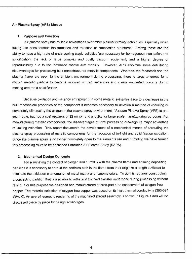
Air Plasma Spray (APS) Shroud
1. Purpose and Function
Air plasma spray has multiple advantages over other plasma forming techniques, especially when
taking into consideration the formation and retention of nanoscaled structures. Among these are the
ability to have a high rate of undercooling (rapid solidification) necessary for homogenous nucleation and
solidification, the lack of large complex and costly vacuum equipment, and a higher degree of
reproducibility due to the increased robotic arm mobility. However, APS also has some debilitating
disadvantages for processing bulk nanostructured metallic components. Whereas, the feedstock and the
plasma flame are open to the ambient environment during processing, there is large tendency for a
molten metallic particle to become oxidized or trap vacancies and create unwanted porosity during
melting and rapid solidification.
Because oxidation and vacancy entrapment (in some metallic systems) leads to a decrease in the
bulk mechanical properties of the component it becomes necessary to develop a method of reducing or
completely eliminating the oxygen in the plasma spray environment. Vacuum Plasma Spray (VPS) is one
such route, but has a cost upwards of $2 million and is bulky for large-scale manufacturing purposes. For
manufacturing metallic components, the disadvantages of VPS processing outweigh its major advantage
of limiting oxidation. This report documents the development of a mechanical means of shrouding the
plasma spray processing of metallic components for the reduction of in-flight and solidification oxidation.
Since the plasma spray is no longer completely open to the elements (air and humidity) we have termed
this processing route to be described Shrouded Air Plasma Spray (SAPS).
2. Mechanical Design Concepts
For eliminating the contact of oxygen and humidity with the plasma flame and ensuing depositing
particles it is necessary to shroud the particles path in the flame from their origin to a length sufficient to
eliminate the oxidation phenomenon of metal matrix and nanomaterials. To do this requires constructing
a concealing partition that is also able to withstand the heat transfer undergone during processing without
failing. For this purpose we designed and manufactured a three-part tube encasement of oxygen-free
copper. The material selection of oxygen-free copper was based on its high thermal conductivity (383-391
W/m-K). An overall isometric rendering of the machined shroud assembly is shown in Figure 1 and will be
discussed piece by piece for design advantages.
4

Figure 1. The three part plasma shroud assembly for the SG-100 air plasma spray gun.
A three part design was chosen for easy removal from the SG-1 00 (Praxair-TAFA Surface
Technologies, Inc.) APS gun for cleaning and maintenance. This design was also conducive for
producing the internal circulating water-cooling cavity that is depicted in the schematic of Figure 2.
chilledmodified cooling water water cooling substrate
pwe channel cavity
Praxair SG-100 APS gun
plasma gas-.
shroud gas
fixed chuck
(D o-ring 0 molten particle return
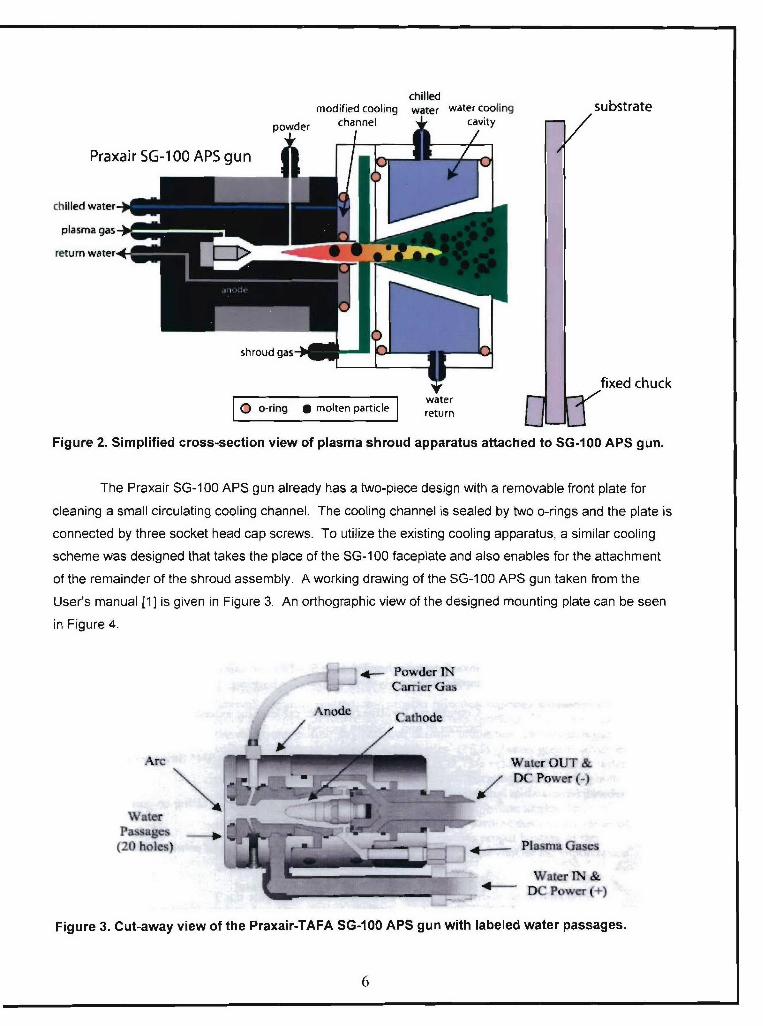
Figure 2. Simplified cross-section view of plasma shroud apparatus attached to SG-100 APS gun.
The Praxair SG-100 APS gun already has a two-piece design with a removable front plate for
cleaning a small circulating cooling channel. The cooling channel is sealed by two o-rings and the plate is
connected by three socket head cap screws. To utilize the existing cooling apparatus, a similar cooling
scheme was designed that takes the place of the SG-100 faceplate and also enables for the attachment
of the remainder of the shroud assembly. A working drawing of the SG-1 00 APS gun taken from the
User's manual [1 ] is given in Figure 3. An orthographic view of the designed mounting plate can be seen
in Figure 4.
SPowder INL Carrier G)as
Arc Watcr OUT &
DC Power(-
Water
(20 holes) Plasma Gas=
Water IN &DC Power(+
Figure 3. Cut-away view of the Praxair-TAFA SG-100 APS gun with labeled water passages.
6

. ........... .- - .. .................... +. ,
a a
2 .
Figure 4. Orthographic drawing of the SG-100 shroud mounting plate.
The mounting plate as seen in Figure 4 utilizes the three screw holes on the SG-1 00 to mount the
shroud assembly that were previously used for mounting a simple cooling face plate. The mounting plate
forms the backbone of the shroud assembly. The inner tube makes a gaseous seal with the mounting
plate and this inner tube slides inside the outer tube that makes a bolted connection to the mounting
plate. The inner tube and outer tube orthographic drawings can be seen in Figures 5 and 6.

AL
S•/ '='|0.225
- 439
4 VI
Figure 5. Orthographic drawing of the shroud inner tube.

j8
C --
Figure 6. Orthographic view of the outer tube that houses the inner tube and connects the
mounting plate.
After assembling the shroud on the SG-1 00 gun, the plasma flame is completely isolated from the
environment until the molten particles emerge from the shroud housing and deposit on the substrate. A
picture of the shroud assembly mounting plate attached on the SG-1 00 gun can be seen in figure 7. A
further image of the shroud assembly and the SG-100 gun in operation on the robot can be seen in figure
8. The inert gas type for this initial experimentation was nitrogen, however any inert gas type can be
chosen to isolate the ensuing plasma particles. The copper shroud parts are cooled using the same
water chiller apparatus that were used primarily to cool the SG-100 plasma gun previously. As can be
seen from the black hoses entering and exiting the assembly in figure 8. The initial test showed no signs
of material degradation from the plasma flame processing or conducting heat.
9
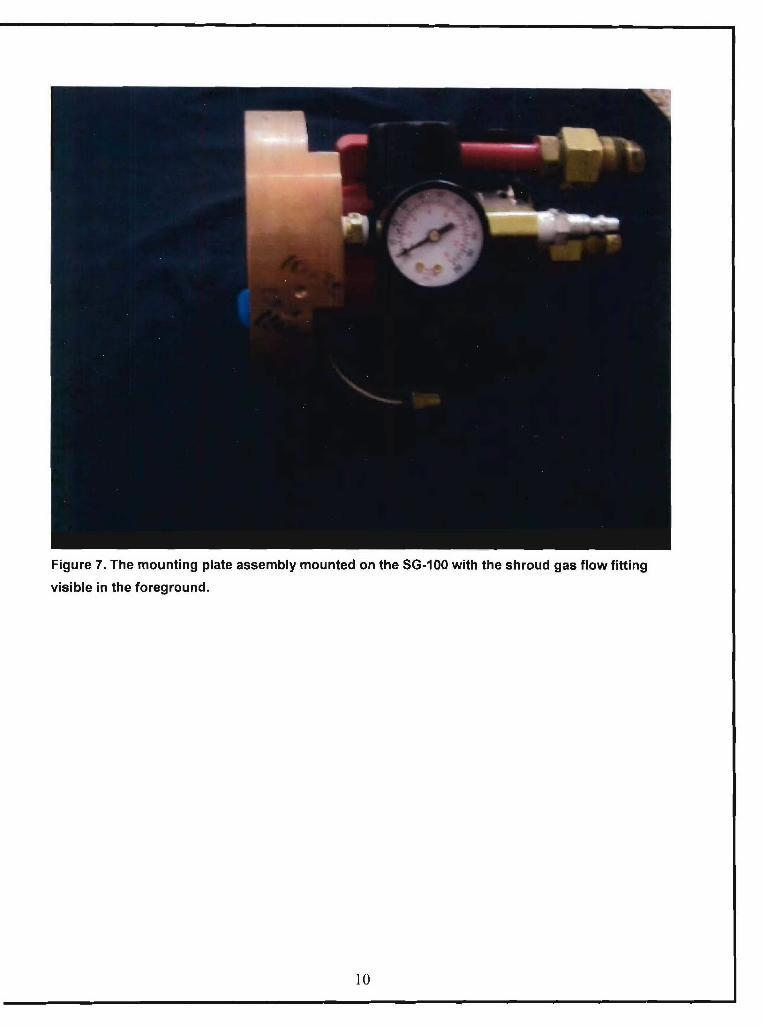
Figure 7. The mounting plate assembly mounted on the SG-100 with the shroud gas flow fitting
visible in the foreground.
10
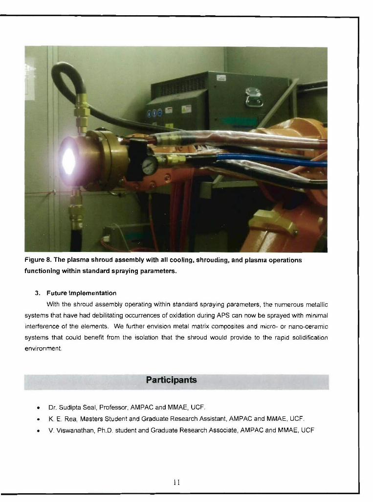
Figure 8. The plasma shroud assembly with all cooling, shrouding, and plasma operations
functioning within standard spraying parameters.
3. Future Implementation
With the shroud assembly operating within standard spraying parameters, the numerous metallic
systems that have had debilitating occurrences of oxidation during APS can now be sprayed with minimal
interference of the elements. We further envision metal matrix composites and micro- or nano-ceramic
systems that could benefit from the isolation that the shroud would provide to the rapid solidification
environment.
* Dr. Sudipta Seal, Professor, AMPAC and MMAE, UCF.
* K. E. Rea, Masters Student and Graduate Research Assistant, AMPAC and MMAE, UCF.
* V. Viswanathan, Ph.D. student and Graduate Research Associate, AMPAC and MMAE, UCF
I1

References
[1] SG-100 User's Manual, Praxair Surface Technologies, Inc. 08/2002.
12