intergrate grating specifications - morionis · intergrate® grating specifications revision 3;...
TRANSCRIPT

Revision: 3 Date: 01-11-2003
INTERGRATE® Grating Specifications
INTERGRATE® Grating Specifications
Revision 3; 01-11-2003 2
1.1 Contents
1.1 Contents 2
2 Used material 4
2.1 Resin 4
2.2 Glass 5
3 Colour 5
4 Dimensions 6
4.1 Standard panel sizes 6
4.2 Mesh 6
5 Thickness 7
5.1 Closed mesh dimensions 8 5.1.1 38 x 38 mesh 8 5.1.2 51 x 51 mesh 9
5.2 Tolerances 10 5.2.1 Standard panels 10 5.2.2 Cut to size panels 10
6 Slip resistancy 10
6.1 Concave surface 10
6.2 Gritted surface 11
7 Covered grating 11
8 Fire resistancy 11
8.1 ASTM E-84-00 Tunnel Test: 11
8.2 M and F test: 11
9 Chemical Resistance 12
9.1 Operating temperature range 12
INTERGRATE® Grating Specifications
Revision 3; 01-11-2003 3
10 Load capacities / deflection 12
10.1 Example 13
10.2 Safety factor 13
11 SAFESTEP® 14
11.1 Closed mesh dimensions 15
12 Mounting clips 15
12.1 M-clips 15
12.2 S-clips 16
12.3 B-clips 16
12.4 F-clips 17
12.5 W-clips 17
12.6 Safestep® Supports 18
12.7 Overview 18
INTERGRATE® Grating Specifications
Revision 3; 01-11-2003 4
2 USED MATERIAL The GRP gratings supplied will be produced with materials equal to the below listed component.
2.1 Resin Seven standard resin systems are available:
ECO-NFR: - Orthophtalic resin - Hallogenfree - Colour: Steel grey ( RAL 9006 ) ECO-FR: - Orthophtalic Fire Retardant resin
- Fire retardant, hallogenfree - Self-extinguishing
- Colour: Blue grey ( RAL 7031 ) ISO-FR: - Isophtalic Fire Retardant - Resin quality: Isophtalic polyester resin - Fire retardant, hallogenfree - Self-extinguishing - DNV - approved - Colour: Green ( RAL 6010 ) FD-FR: - Food Approved Isophtalic Fire Retardant - Resin quality: isophtalic polyester resin - Fire retardant, hallogenfree - Self-extinguishing - Colour: Light-Grey ( RAL 7040 ) VE-FR: - Vinylester Fire Retardant - Resin quality: Vinylester resin - Fire retardant, hallogenfree - DNV - approved - Self-extinguishing - Colour: Orange ( RAL 2002 ) ISO-XFR: - Isophtalic extra Fire Retardant - Resin quality: Isophtalic polyester resin - Extreme Fire retardant, - Self-extinguishing - Colour: Dark Grey ( RAL 7043 ) IGF-FR: - Pultruded Phenolic Fire Retardant Grating - Resin quality: Phenolic - Fire retardant, self-extinguishing
- Extreme Low Smoke emission - US Coast Guard approved - ABS certified.
- Colour: Light brown.
INTERGRATE® Grating Specifications
Revision 3; 01-11-2003 5
ECO-NFR: Orthophtalic, developed for applications that only require
outstanding corrosion resistance. ECO-FR: Orthophtalic Fire retardant, developed for applications that only
require outstanding corrosion resistance. ISO-FR: Isophtalic Fire Retardant, for most applications in corrosive
environments. FD-FR: Isophtalic Fire Retardant, special resin mix for the Food &
Beverage industry. VE-FR: Vinylester Fire Retardant, for higher chemical (corrosion)
resistance. ISO-XFR: Isophtalic Extra Fire Retardant, developed for applications that
require outstanding fire retardancy capabilities. IGF-FR: Phenolic Fire Retardant, extreme Low Smoke emission. (US Coast Guard approved)
2.2 Glass The reinforcement of the gratings consists of continuous bi-directional filament rovings (E-glass).The resin/glass ratio of the gratings is approximately 70 / 30 % by weight, in order to obtain a high level of corrosion resistancy. 3 COLOUR Standard colours for the four resinsystem: ECO-NFR: steel grey (RAL 9006) ECO-NR: blue grey (RAL 7031) ISO-FR: green (RAL 6010) FD-FR: light-grey (RAL 7040) VE-FR: orange (RAL 2002) ISO-XFR: dark grey (RAL 7043) IGF-FR: light brown Other colours are availabe on request.

INTERGRATE® Grating Specifications
Revision 3; 01-11-2003 6
4 DIMENSIONS
4.1 Standard panel sizes Width [ mm ]
Length [ mm ]
Name Thickn. [ mm ]
Mesh [ mm ]
Open area [ % ]
Weight [ kg / m² ]
Weight per panel [ kg ]
1225 914 1219 1000 1000 1225 914 1219 1219 1524 1645 1219 585 914
1219
4580 3048 2438 1990 2980 2980 3048 2438 3658 3048 2978 3658 2980 6096 6096
Screengrid®
Micromesh® Micromesh®
Micromesh®
Safestep®
Pultruded Pultruded
13 26 26 30 30 30 38 38 38 38 38 51 38 38 38
51 38 38 19 19 38 38 38 38 38 19 51 38 38 38
78 70 70 48 48 70 70 70 70 70 48 72 70 60 60
3.9 12.2 12.2 17.0 17.0 14.1 18.3 18.3 18.3 18.3 21.9 19.5 18.3 15.6 15.6
21.9 34.0 36.5 34.0 50.7 51.5 51.0 54.5 81.5 85.0
107.3 87.0 31.9 86.9
115.9
4.2 Mesh The gratings have a square mesh pattern to obtain multidirectional strength. The mesh size is approximately 38 x 38 mm. resulting in an open area of ±70%. The 51 mm thick gratings have a mesh pattern of 51x51 mm. resulting in an open area of ±72%. Gratings on platforms and walkways crossing a passageway, workplace or equivalent beneath, shall not allow a ball with 15 mm diameter to pass through. Therefore the Micromesh® has an inside mesh dimension of approx. 13 mm. The meshsizes listed are the dimensions from bar to bar. The inside mesh dimensions are therefore smaller: Thickness [mm] Mesh [mm] Inside mesh [mm] 13 51 x 51 45 x 45 26 / 30 38 x 38 32 x 32 30 (Micromesh®) 19 x 19 13 x 13 38 (Micromesh®) 19 x 19 13 x 13 51 51 x 51 43 x 43 38 (Pultruded) 38 (1 ½”) * 23 * bearing bar centers
INTERGRATE® Grating Specifications
Revision 3; 01-11-2003 7
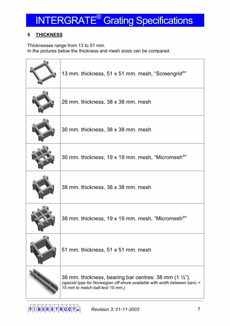
5 THICKNESS Thicknesses range from 13 to 51 mm. In the pictures below the thickness and mesh sizes can be compared.
13 mm. thickness, 51 x 51 mm. mesh, “Screengrid®”
26 mm. thickness, 38 x 38 mm. mesh
30 mm. thickness, 38 x 38 mm. mesh
30 mm. thickness, 19 x 19 mm. mesh, “Micromesh®”
38 mm. thickness, 38 x 38 mm. mesh
38 mm. thickness, 19 x 19 mm. mesh, “Micromesh®”
51 mm. thickness, 51 x 51 mm. mesh
38 mm. thickness, bearing bar centres: 38 mm (1 ½”). (special type for Norwegian off-shore available with width between bars: < 15 mm to match ball-test 15 mm.)
INTERGRATE® Grating Specifications
Revision 3; 01-11-2003 8
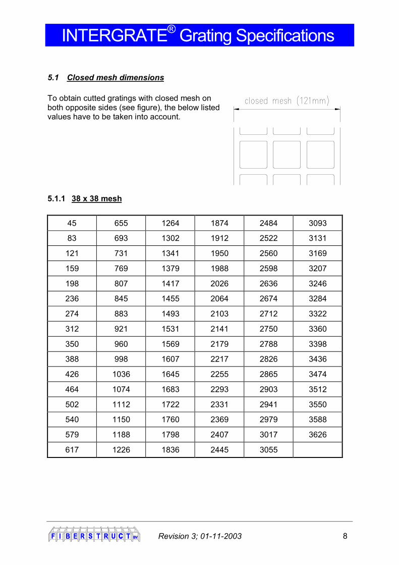
5.1 Closed mesh dimensions To obtain cutted gratings with closed mesh on both opposite sides (see figure), the below listed values have to be taken into account.
5.1.1 38 x 38 mesh
45 655 1264 1874 2484 3093
83 693 1302 1912 2522 3131
121 731 1341 1950 2560 3169
159 769 1379 1988 2598 3207
198 807 1417 2026 2636 3246
236 845 1455 2064 2674 3284
274 883 1493 2103 2712 3322
312 921 1531 2141 2750 3360
350 960 1569 2179 2788 3398
388 998 1607 2217 2826 3436
426 1036 1645 2255 2865 3474
464 1074 1683 2293 2903 3512
502 1112 1722 2331 2941 3550
540 1150 1760 2369 2979 3588
579 1188 1798 2407 3017 3626
617 1226 1836 2445 3055
INTERGRATE® Grating Specifications
Revision 3; 01-11-2003 9
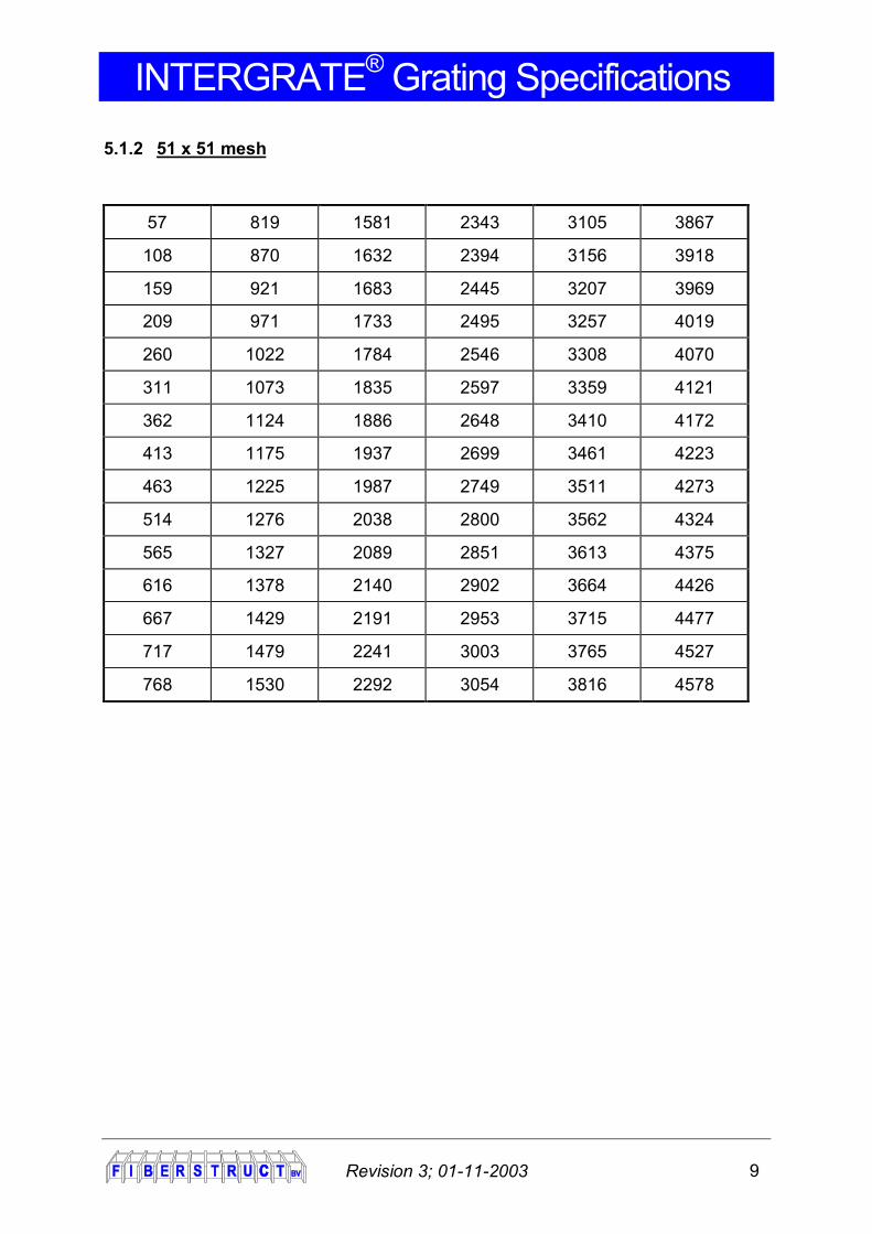
5.1.2 51 x 51 mesh
57 819 1581 2343 3105 3867
108 870 1632 2394 3156 3918
159 921 1683 2445 3207 3969
209 971 1733 2495 3257 4019
260 1022 1784 2546 3308 4070
311 1073 1835 2597 3359 4121
362 1124 1886 2648 3410 4172
413 1175 1937 2699 3461 4223
463 1225 1987 2749 3511 4273
514 1276 2038 2800 3562 4324
565 1327 2089 2851 3613 4375
616 1378 2140 2902 3664 4426
667 1429 2191 2953 3715 4477
717 1479 2241 3003 3765 4527
768 1530 2292 3054 3816 4578

INTERGRATE® Grating Specifications
Revision 3; 01-11-2003 10
5.2 Tolerances The following tolerances have to be taken into account:
5.2.1 Standard panels Length: ± 1 mm. Width: ± 1 mm. Thickness: ± 2 mm. Warping: < 10 mm / m1. (Not valid for 13 mm thickness an HLU-panels).
5.2.2 Cut to size panels Length: ± 4 mm. Width: ± 4 mm. Thickness: ± 2 mm. Warping: < 10 mm / m1. (Not valid for 13 mm thickness).
6 SLIP RESISTANCY
6.1 Concave surface The gratings have a concave surface to obtain slip resistancy. The slip resistancy meets: R13 according to BGR 181 and DIN 51130.

INTERGRATE® Grating Specifications
Revision 3; 01-11-2003 11
6.2 Gritted surface Optionally the gratings can be provided with a gritted surface. The slip resistancy also meets: R13 according to BGR 181 and DIN 51130. 7 COVERED GRATING The gratings can optionally be covered. Standard the surface is provided with grit. The increase of thickness of covered gratings is approx. 3 – 5 mm. The warping data (4.4.1 & 4.4.2) are not applicable on covered gratings. The molding and curing of Fiberstruct HLU-gratings can produce internal stresses that may cause the panel to warp. In some cases, this warpage may increase when HLU-panels are cut into smaller pieces. In certain situations, this out-of-flat condition can result in tripping hazards and other problems. This is one of the reasons we strongly recommend the use of hold down methods, such as clips. In situations where hold-down procedures are not possible, we do not recomment HLU-panels. 8 FIRE RESISTANCY
8.1 ASTM E-84-00 Tunnel Test: Illustrates the performance of GRP during a fire situation. It measures the flame spread and smoke emission. A sample of GRP material is placed in the top of a tunnel. A large gas burner is placed at the entrance while at the end a chimney is placed. Both the spread of flame and the smoke generated during the tests are compared to red oak and cement board to determine flame spread and smoke index.
8.2 M and F test: These tests are to determine the flame spread according to the french standards: NFP 92-501 ( M-test ) and the smoke emission NFF 16-101 ( F-test ). Our ISO-FR and VE-FR Series gratings are DNV-approved.

INTERGRATE® Grating Specifications
Revision 3; 01-11-2003 12
When tested, the below listed results are found:
QUALITY ASTM E84-00 NFP 92-501
FLAME SPREAD SMOKE INDEX CLASS M F
ECO-FR ≤ 35 680 1 M-1 F-1
ISO-FR ≤ 25 345 1 M-1 F-1
FD-FR ≤ 25 375 1 M-1 F-1
VE-FR ≤ 20 360 1 M-1 F-1
ISO-XFR ≤ 15 920 1 - -
IGF-FR ≤ 20 10 1 - -
9 CHEMICAL RESISTANCE See appendix for the Chemical Resistance guide.
9.1 Operating temperature range To avoid serious reduction of the mechanical and chemical properties of the gratings, recommended temperature ranges are given for the different resin system. ECO-NFR / ECO-FR: -40 / +60 ºC ISO-FR / FD-FR / ISO-XFR: -40 / +78 ºC VE-FR: -40 / +98 ºC These temperature ranges are only applicable in standard environments. If not, the chemical resistance guide should be consulted. Note: for short and infrequent periodes of time these values can be exceeded. 10 LOAD CAPACITIES / DEFLECTION In the appendix, you can find the deflection table. In the deflection table three types of loads are given: Concentrated Load [kg] Uniform distributed Load [kg/m2] Line Load [kg/305mm]

INTERGRATE® Grating Specifications
Revision 3; 01-11-2003 13
Concentrated Load: The load is applied in the middle of a standard full panel. Uniform distributed Load: The load is applied uniformly on the whole area of the
grating. Line Load: The line load is applied on a gratings with a width of 305
mm. These values can be used to calculate the deflection on unsupported edges of a grating.
For each type of grating and each span, the load is given for a deflection of 1% : span / deflection = 100. De deflection is based on panels that are supported on two sides. For gratings that are supported on four sides the deflection will be less than given in the table >> consult Fiberstruct. There is a lineair relation between the load and the deflection at equal spans.
10.1 Example For a 38 mm thick grating with a free span of 900 mm, the maximum uniform distributed load with a deflection of 1% is 776 kg/m2 (See deflection table).
1. When the required deflection is for example 0,8% (L / D 125), the max. load can be easily found:
max. load: 776 x (0,8/1%) = 621 kg/m2
2. When the required maximum load is 850 kg, the deflection can be calculated:
deflection: 850 / 776 x 1% = 1,1% (0,011 x 900 = 9,9mm)
10.2 Safety factor The deflection of the gratings is in 99% of the applications the primary design value. The deflection is limitted by the safe feeling the grating has to give and not by the mechanical allowable deflection. In the deflection table, the maximum recomended loads can be found for each grating at each span. The ultimate capacity represents the load by wich the grating is seriously damaged. For the above example at 1% deflection, the safetyfactor would be: S.F. = 8963 / 776 = 11,6

INTERGRATE® Grating Specifications
Revision 3; 01-11-2003 14
11 SAFESTEP® Safestep® stairtreads are specialy designed gratings for stairs. The Safestep® stairtreads are provided with an extra-reinforced gritted nose which results in excellent anti-slip properties and minimal deflection.

INTERGRATE® Grating Specifications
Revision 3; 01-11-2003 15
11.1 Closed mesh dimensions
Length Width
With
thes
e le
ngth
, 8 tr
eads
(wid
th <
277
) can
be
cut o
ut o
f a
stan
dard
Saf
este
p pa
nel (
leng
thw
ise)
45
617
2 tr
eads
can
be
cut
oppo
site
to e
ach
othe
r 48
83 655 86
121 693 124
159 6
trea
ds (w
idth
< 2
77) 731 162
198 769 200
236 807 239
274 845 277
312 883
1 tr
ead
can
be c
ut w
idth
wis
e 315
350 921 353
388 960 391
426
4 tr
eads
(w
idth
< 2
77)
998 429
464 1036 467
502 1074 505
540 1112 543
579 1150 12 MOUNTING CLIPS Highly quality stainless steel mounting material in Austentic A4 type steel. A4 austentic stainless steel represents the most corrosion-resistant steelgroup also referred as “acid-proof”. DIN 267 Teil 11 / A.
12.1 M-clips
M-clips connect the grating directly to supporting beam. The installation is easy, but the supporting beam has to be drilled.
INTERGRATE® Grating Specifications
Revision 3; 01-11-2003 16
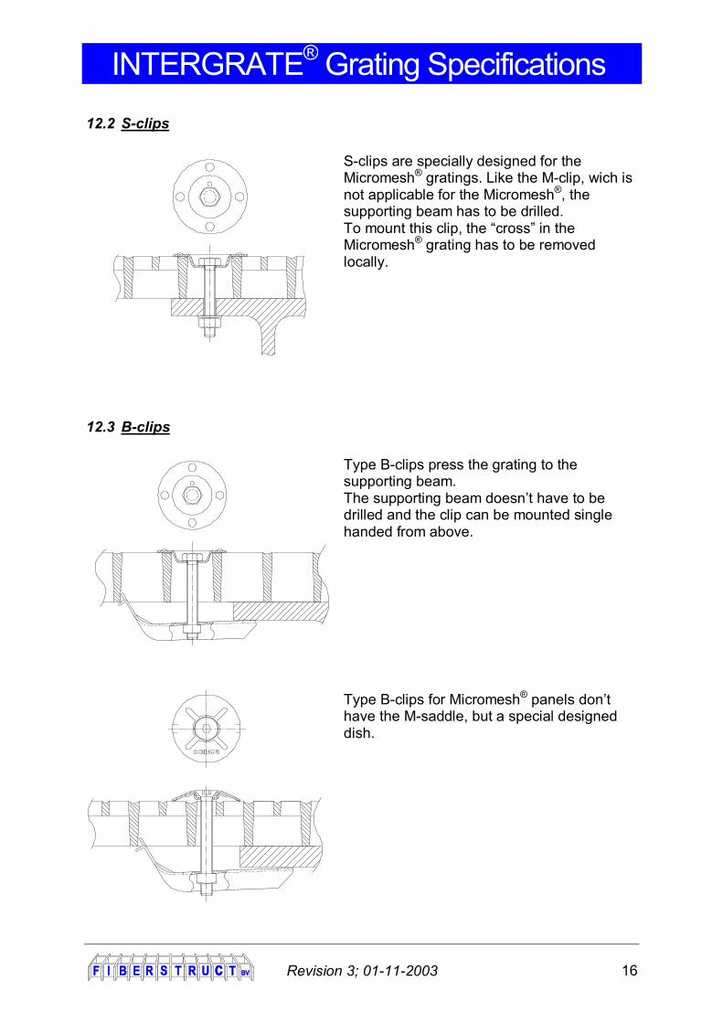
12.2 S-clips
S-clips are specially designed for the Micromesh® gratings. Like the M-clip, wich is not applicable for the Micromesh®, the supporting beam has to be drilled. To mount this clip, the “cross” in the Micromesh® grating has to be removed locally.
12.3 B-clips Type B-clips press the grating to the supporting beam. The supporting beam doesn’t have to be drilled and the clip can be mounted single handed from above.
Type B-clips for Micromesh® panels don’t have the M-saddle, but a special designed dish.

INTERGRATE® Grating Specifications
Revision 3; 01-11-2003 17
12.4 F-clips
F-clips are assembled for connecting unsupported grating-endings to each other to prevent excessive deflection.
12.5 W-clips
W-clips are specialy designed to mount HLU-type gratings. The cover of the HLU and the supporting beams have to be drilled.
INTERGRATE® Grating Specifications
Revision 3; 01-11-2003 18
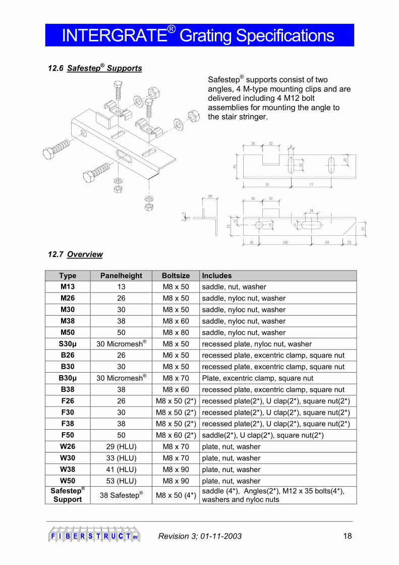
12.6 Safestep® Supports Safestep® supports consist of two angles, 4 M-type mounting clips and are delivered including 4 M12 bolt assemblies for mounting the angle to the stair stringer.
12.7 Overview
Type Panelheight Boltsize Includes M13 13 M8 x 50 saddle, nut, washer M26 26 M8 x 50 saddle, nyloc nut, washer M30 30 M8 x 50 saddle, nyloc nut, washer M38 38 M8 x 60 saddle, nyloc nut, washer M50 50 M8 x 80 saddle, nyloc nut, washer S30μ 30 Micromesh® M8 x 50 recessed plate, nyloc nut, washer B26 26 M6 x 50 recessed plate, excentric clamp, square nut B30 30 M8 x 50 recessed plate, excentric clamp, square nut
B30μ 30 Micromesh® M8 x 70 Plate, excentric clamp, square nut B38 38 M8 x 60 recessed plate, excentric clamp, square nut F26 26 M8 x 50 (2*) recessed plate(2*), U clap(2*), square nut(2*) F30 30 M8 x 50 (2*) recessed plate(2*), U clap(2*), square nut(2*) F38 38 M8 x 50 (2*) recessed plate(2*), U clap(2*), square nut(2*) F50 50 M8 x 60 (2*) saddle(2*), U clap(2*), square nut(2*) W26 29 (HLU) M8 x 70 plate, nut, washer W30 33 (HLU) M8 x 70 plate, nut, washer W38 41 (HLU) M8 x 90 plate, nut, washer W50 53 (HLU) M8 x 90 plate, nut, washer
Safestep® Support 38 Safestep® M8 x 50 (4*) saddle (4*), Angles(2*), M12 x 35 bolts(4*),
washers and nyloc nuts

INTERGRATE® Grating Specifications
Revision 3; 01-11-2003 19