interferograms of window wavefront deformations as a ... · interferograms of window wavefront...
TRANSCRIPT

INTERFEROGRAMS OF WINDOW WAVEFRONT DEFORMATIONS AS A MEASURE OF ANGULAR DEVIATIONS TO A LINE OF SIGHT
by Thomus M . IVulsh m d Duvid N. Wamer, Jr.
Ames Reseurch Center Moffett Field, CuZ$
N A T I O N A L A E R O N A U T I C S A N D S P A C E A D M I N I S T R A T I O N W A S H I N G T O N , D. C. A P R I L 1970
https://ntrs.nasa.gov/search.jsp?R=19700014972 2018-06-14T15:57:31+00:00Z
TECH LIBRARY KAFB, NM
19. Security Classif. (of this report)
Unclassified
I llllil1111111111111111111111111 Ulll1111 Ill
20. Security Classif. (of this page) 21- NO. of Pages 22. Price'
Unclassified I 13 I $3.00
2. Government Accession No. I 1. Report No.
NASA TN D-5749
4. T i t l e ond Subtitle INTERFEROGRAMS OF WINDOW WAVEFRONT DEFORMATIONS AS A MEASURE OF ANGULAR DEVIATIONS TO A LINE OF SIGHT
7. Author(s) Thomas M. Walsh and David N. Warner, Jr.
9. Performing Organization Name ond Address NASA Ames Research Center Moffett Field, Calif. 94035
12. Sponsoring Agency Nome and Address
NATIONAL AERONAUTICS AND SPACE ADMINISTRATION Washington, D. C., 20546
15. Supplementary Notes
013240s 3. Recipient's Catalog No.
5. Report Date April 1910
6. Performing Orgonizotion Code
8. Performing Orgonizotion Report No.
A-3014
0. Work Unit No. 125-17-02-13-00-21
1 . Contract or Grant No.
3. Type of Report and Period Covered
TECHNICAL NOTE
4. Sponsoring Agency Code
16. Abstroct
An interferogram of the wavefront deformation to a flat wave caused by an aircraft o r spacecraft window contains all the e r r o r contribution effects of the window. at a given point, which yields the angular deviation to a line of sight through the point. The interferogram a s used in this study is a two-dimensional photo representing the three-dimensional relationship of the transmitted wave relative to the flat reference wave. The progression from light to dark fringes i s the progression of the third dimension normal to the photo, and the fringes a r e thus similar to contour lines on a topographic map. To demonstrate the ability to obtain interfero- grams, to analyze interferograms, and to achieve sufficient accuracy, an aircraft window and spacecraft window were studied in an experimental test. The deviations to a line of sight were derived from transmitted wave interferograms obtained in the laboratory and were also measured precisely by an autocollimator system. The standard deviation of the transmitted wave deviations derived from interferograms relative to directly measured deviations was 0 . 1 second of a rc , indicating that the transmitted wave interferogram method is a good tool for window e r r o r determination.
The interferogram may be analyzed to determine the slope of this wavefront
17. Key Words Suggested by Author(s)
Interferometry Line-of-sight deviations Window (aperture) Wavefront deformations Space navigation Sextant
18. Distribution Stotement
Unclassified - Unlimited

INTERFEROGRAMS OF WINDOW WAVEFRONT DEFORMATIONS AS
A MEASURE OF ANGULAR DEVIATIONS TO
A L I N E OF SIGHT
By Thomas M . Walsh and David N . Warner, J r .
Ames Research Center
SUMMARY
An in te r fe rogram of t h e wavefront deformation t o a f l a t wave caused by
The in te r fe rogram may be analyzed t o determine t h e s l o p e of an a i r c ra f t o r s p a c e c r a f t window conta ins a l l t h e e r r o r con t r ibu t ion e f f e c t s of t he window. t h i s wavefront a t a given p o i n t , which y i e l d s t h e angular dev ia t ion t o a l i n e of s i g h t through t h e p o i n t . The in te r fe rogram as used i n t h i s s tudy i s a two-dimensional photo r ep resen t ing t h e three-dimensional r e l a t i o n s h i p of t h e t r ansmi t t ed wave r e l a t i v e t o t h e f l a t re ference wave. The progress ion from l i g h t t o dark f r i n g e s i s t h e progress ion of t h e t h i r d dimension normal t o t h e photo, and the f r i n g e s a r e thus s imilar t o contour l i n e s on a topographic map. To demonstrate t h e a b i l i t y t o o b t a i n interferograms , t o analyze i n t e r f e r o - grams , and t o achieve s u f f i c i e n t accuracy, an a i r c r a f t window and s p a c e c r a f t window were s tud ied i n an experimental t e s t . The devia t ions t o a l i n e of s i g h t were der ived from t r ansmi t t ed wave interferograms obta ined i n t h e labo- r a t o r y and were a l s o measured p r e c i s e l y by an au tocol l imator system. The s tandard dev ia t ion of t h e t r ansmi t t ed wave devia t ions der ived from i n t e r f e r o - grams r e l a t i v e t o d i r e c t l y measured dev ia t ions was 0 . 7 second of a r c , i n d i - c a t i n g t h a t t h e t r ansmi t t ed wave in te r fe rogram method i s a good t o o l f o r window e r r o r de te rmina t ion .
INTRODUCTION
Because of t h e unpara l le l i sm of t h e pane su r faces , t h e bowing of t h e panes due t o environmental p ressures and temperatures , and anomalies i n t h e g l a s s , a i rc raf t and s p a c e c r a f t windows cause angular dev ia t ion e r r o r s i n a l i n e o f s i g h t pass ing through t h e g l a s s of t h e windows. These e r r o r s d i r e c t l y a f f e c t naviga t ion s e x t a n t measurements , such as those of NASA Experiment T-2 on the Gemini GT-12 f l i g h t and those measurements made through windows of t h e NASA C V - 9 9 0 research a i r c ra f t . The window e r r o r co r rec t ions f o r t h e T-2 experiment are found i n r e fe rence 1 and were determined by d i r e c t measurement with a l a r g e ape r tu re au tocol l imator . A i r c r a f t window e r r o r s of t h e l a t t e r experiment a r e found i n re ference 2 and were determined by computation i n a s o p h i s t i c a t e d ray trace program.
The advantages o f t h e method descr ibed h e r e i n a r e i t s r e l a t i v e ease and dependabi l i ty as compared with t h e two methods previous ly mentioned. The au tocol l imator method is a very time-consuming and d i f f i c u l t t a s k , as
I

r e fe rence 3 i n d i c a t e s ( a minimum of 1200 measurements was made). Autocol l i - mator measurements are prone t o ope ra to r e r r o r s and equipment e r r o r s . add i t ion , t h e au toco l l ima to r i s , i n gene ra l , l i m i t e d t o examining only a few loca t ions because of t h e time requ i r ed f o r t e s t i n g a l l p o s s i b l e ape r tu re s ; consequently, some information i s l o s t t h a t may b e d e s i r e d a t a la te r d a t e . The ray t r a c e method used i n r e fe rence 2 n e c e s s i t a t e s t h e assumption of i n i - t i a l condi t ions . For a mult ipane window, such as a four-pane spacec ra f t win- dow, t h e v a l i d i t y of t h e r e s u l t s would b e only as good as t h e assumptions. If t h e window edge c o n s t r a i n t s a r e unknown, s o p h i s t i c a t e d i n t e r f e r o m e t r i c tech- niques must b e used t o determine d i s t o r t i o n of t h e window panes under p re s su re condi t ions be fo re t h e l i ne -o f - s igh t dev ia t ions can b e computed. The correc- t i o n s i n r e fe rence 2 were f o r a s ing le-pane a i r c ra f t window.
I n
The advantage of t h e i n t e r f e r o m e t r i c method o f t h i s s tudy is t h a t i t produces a permanent record of a wavefront a f t e r it has passed through any number of window panes, which may be inf luenced by (1) any combination of wedge angles ; (2) index of r e f r a c t i o n inhomogeneities (3) s u r f a c e shapes d i s - t o r t e d during manufacture; and (4) s u r f a c e shapes d i s t o r t e d by environmental p re s su res , temperature d i f f e r e n c e s , and mechanical f o r c e s due t o undefined edge condi t ions . A l l ape r tu re s a r e covered by one exposure s o no information i s l o s t because o f t h e p re s s o f time. The i n t e r f e r o m e t r i c method i s r e l a - t i v e l y easy compared wi th t h e au tocol l imator method i n regard t o t h e problems of apparatus se tup , time expended, maintaining p r e c i s i o n , opera tor f a t i g u e , e t c . The in te r fe rogram can b e i n t e r r o g a t e d a t any l a t e r d a t e f o r window e r r o r , s o only t h e s p e c i f i c ape r tu re of i n t e r e s t need by examined a t t h e time the o r i g i n a l naviga t ion d a t a are reduced.
The purpose of t h i s s tudy was t o i n v e s t i g a t e an i n t e r f e r o m e t r i c method of determining window e r r o r c o r r e c t i o n s . The proposed method had two main s t e p s : (1) a re ference f l a t wavefront was in t roduced i n t o a window under s imulated space environmental cond i t ions , and an in te r fe rogram of t h e e x i s t i n g d i s t o r t e d wavefront ( h e r e a f t e r c a l l e d t h e t r ansmi t t ed wavefront) was obtained; (2) t h e in te r fe rogram was analyzed t o ob ta in t h e window dev ia t ion e r r o r s . The purpose of t h i s s tudy was t o implement and v a l i d a t e t h e method by showing t h a t :
1. A re ference f l a t wavefront may b e made t o e n t e r a tes t window and a s u i t a b l e t r ansmi t t ed wave in te r fe rogram may be obta ined i f t h e proper equipment, procedures , and techniques are used.
2 . (a) The in te r fe rogram s o obtained r ep resen t s t h e d i s t o r t i o n t o a f l a t wavefront caused by t h e window. (b) The normal t o t h e d i s t o r t e d wavefront i s t h e d i r e c t i o n of t h e wavefront a t each coord ina te p o i n t and, as such, i s t h e d i r e c t i o n of t h e devia ted ray a t each p o i n t .
3 . The in te r fe rogram can be analyzed by procedures der ived h e r e i n t o ob ta in t h e dev ia t ion i n seconds of a r c .
4 . Actual window dev ia t ions s o determined compare c l o s e l y wi th d i r e c t l y measured l i ne -o f - s igh t dev ia t ions f o r both a s p a c e c r a f t window and an a i r c r a f t window.
2
1
One s p a c e c r a f t window and one a i r c ra f t window were inves t iga t ed . The a i rc raf t window was chosen f o r t h e s tudy because i t represented a lower qual- i t y o p t i c a l window t h a t would y i e l d high dev ia t ions . ‘ n u s t h e a b i l i t y of t h e in te r fe rogram method could be t e s t e d f o r l a r g e as w e l l as small dev ia t ions . The angular dev ia t ions t o a l i n e of s i g h t were measured a t s e v e r a l ape r tu re s and incidence angles by au tocol l imator i n l abora to ry tes ts . Almost s imultan- eously, t r ansmi t t ed wave in te r fe rograms were a l s o obtained. The i n t e r f e r o - grams were analyzed, dev ia t ions were computed from them, and t h e r e s u l t s were compared wi th t h e measured dev ia t ions . ‘ f i e o b j e c t i v e of t h e t e s t d a t a w a s t o show t h a t t h e in te r fe rogram r e s u l t s were comparable t o d i r e c t measurement r e s u l t s and, a t t h e same time, demonstrate t h a t l abora tory o p t i c a l equipment and t h e procedures and techniques used could genera te an in te r fe rogram of s u f f i c i e n t f i d e l i t y .
The d i f f i c u l t i e s apd l i m i t a t i o n s o f t h e a l t e r n a t i v e methods mentioned f o r determining window e r r o r s provided t h e i n c e n t i v e f o r t h i s s tudy . The u t i l i z a t i o n of t h i s in te r fe rogram a n a l y s i s method i s based, however, on t h e a b i l i t y t o ob ta in a t r ansmi t t ed wave in te r fe rogram of t h e window. descr ibes a method f o r ob ta in ing , through l a r g e g l a s s pane ls , a t r ansmi t t ed wave measurement us ing a Fizeau in t e r f e romete r . l imi t ed t o windows t h a t can be adapted t o a Fizeau s e t u p . Interferograms of Gemini windows were obta ined as descr ibed i n r e fe rence 3. i n t h e case of t h e Apollo window, which is p o t t e d i n t o p l ace i n t h e Apollo spacec ra f t s h e l l and has an environmental p re s su re of about 5 p s i a i n s i d e t h e s h e l l , t h e necessary interferograms would be obta ined with some d i f f i c u l t y . Reference 5 po in t s up some of t he problems and s o l u t i o n s t o in t e r f e romet ry i n a h o s t i l e environment and i s p e r t i n e n t t o ob ta in ing in te r fe rograms of t h e Apollo window. While t h e a c t u a l phys ica l adap ta t ion of t h e in t e r f e romete r t o a p a r t i c u l a r t a s k i s very important t o t h e use of t h e proposed method, t h i s s tudy w a s no t in tended t o so lve such s p e c i f i c problems.
Reference 4
I t i s very simple b u t
APPARATUS AND PROCEDURE
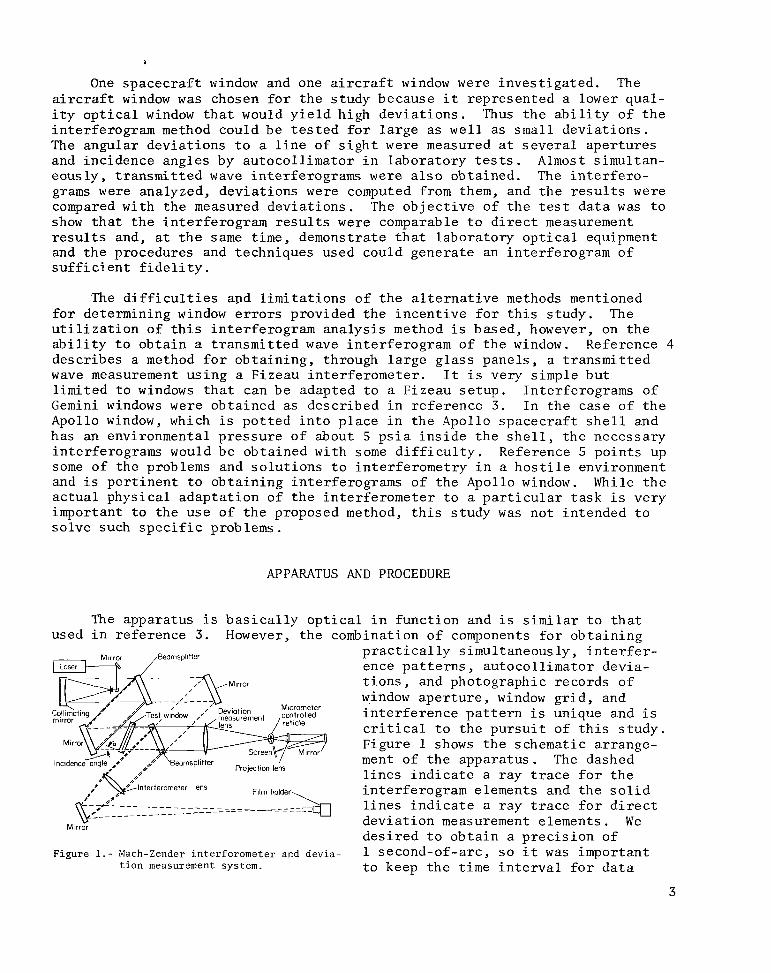
The apparatus i s b a s i c a l l y o p t i c a l i n func t ion and i s s imilar t o t h a t used i n re ference 3. However, t h e combination of components f o r ob ta in ing
Figure 1.- Mach-Zender interferometer and devia- tion measurement system.
p r a c t i c a l l y s imultaneously, i n t e r f e r - ence p a t t e r n s , au tocol l imator devia- t i o n s , and photographic records of window a p e r t u r e , window g r i d , and i n t e r f e r e n c e p a t t e r n i s unique and i s c r i t i c a l t o t h e p u r s u i t o f t h i s s tudy . Figure P shows t h e schematic arrange- ment of t h e appara tus . The dashed l i n e s i n d i c a t e a ray t r a c e f o r t h e in te r fe rogram elements and t h e s o l i d l i n e s i n d i c a t e a ray t r a c e f o r d i r e c t dev ia t ion measurement elements. We d e s i r e d t o o b t a i n a p r e c i s i o n of 1 second-of-arc , s o i t was important t o keep t h e t ime i n t e r v a l f o r d a t a
3

I I II I II 1-11111111111111 I I I I 111 I I IIIIIIIIIIIIIIIIIII1111IIIIII.I 111111111 II II II 11.1 --1..-..1-- ...,, ,--. ___.- I
a c q u i s i t i o n t o a minimum (15 minutes) t o avoid temperature s h i f t s and d r i f t due t o mechanical causes. Therefore , t h e t e s t window was untouched between a c q u i s i t i o n of in te r fe rograms and dev ia t ion d a t a , and as many o p t i c a l elements as p o s s i b l e were used i n common wi th no c r i t i c a l element adjustment be ing necessary i n t h e d a t a a c q u i s i t i o n time i n t e r v a l . The l i g h t source was a 632.8-nanometer H e - N e laser, which was focused i n t o a long foca l length , para- b o l i c mi r ro r t o gene ra t e a h igh ly co l l imated bundle o f l i g h t . l i g h t then en tered a Mach-Zender in t e r f e romete r con ta in ing t h e t e s t window. Light from both pa ths of t h e in t e r f e romete r was brought t o focus a t t h e f i l m p l a t e by t h e i n t e r f e r o m e t e r l ens s o t h a t a wi re g r i d on t h e window s u r f a c e was i n sharp focus a t t h e f i l m p l a t e . Simulataneously, f o r t h e au tocol l imator measurements, some l i g h t through t h e window pa th of t h e in t e r f e romete r was brought t o focus by a d e v i a t i o n measurement l ens on a r e t i c l e mounted on a x-y c ross s l i d e . sc reen f o r p r e c i s e s e t t i n g of r e t i c l e on the s p o t image.
This bundle of
The l i g h t s p o t and r e t i c l e were i n t u r n p ro jec t ed on a
The procedure was t o a d j u s t t h e in t e r f e romete r f o r zero f r i n g e s with t h e in t e r f e romete r empty ( i . e . , wi thout t he window) and a l s o t o ob ta in an i n i t i a l x-y micrometer dev ia t ion reading wi th t h e c rossbars on t h e focused laser s p o t . The window was then i n s e r t e d t o a d e s i r e d inc idence ang le , and a l l d a t a f o r t h a t incidence angle were obta ined before t h e window was r o t a t e d t o a new inc idence angle o r a new plane of inc idence .
Two windows were used i n the t e s t program: a "spacecraf t" window, which r ep resen t s high o p t i c a l q u a l i t y , and an " a i r c r a f t " window, which r ep resen t s moderate o p t i c a l q u a l i t y . def ined he re as one producing l e s s than 10-seconds-of-arc dev ia t ion t o a l i n e o f s i g h t , whereas moderate o p t i c a l q u a l i t y is a r b i t r a r i l y def ined as produc- ing up t o 40-seconds-of-arc dev ia t ion . t o l e r a t e d from a window s u i t a b l e f o r s p a c e c r a f t o r a i rc raf t naviga t ion mea- surements. mounted i n a modified Gemini-type frame and p r e s s u r i z e d t o 14.7-psi gage between t h e panes. This was similar t o a s p a c e c r a f t environment and induced bowing of t h e panes t o produce r e a l i s t i c d i s t o r t i o n t o a p lane t r ansmi t t ed wave. The a i r c r a f t window had been i n s t a l l e d i n a Convair 990 a i r c r a f t used i n s c i e n t i f i c experiments a t h igh a l t i t u d e s . I t was a s i n g l e , t h i c k pane of g l a s s , mounted i n t h e frame used i n the a i r c r a f t .
The high o p t i c a l q u a l i t y window i s a r b i t r a r i l y
This i s almost more than could be
The s p a c e c r a f t window used two Gemini r igh t -hand window panes
By d e f i n i t i o n , t h e p l ane o f incidence conta ins t h e inc iden t ray and is perpendicular t o t h e window. incidence r e l a t i v e t o t h e window as the angle 8,. The planes of incidence chosen f o r rays f o r which dev ia t ions were t o b e measured were p a r a l l e l t o t h e plane conta in ing t h e h o r i z o n t a l c e n t e r l i n e of t h e window. Figure 3 shows t h i s l i n e and t h e ape r tu re s a long t h e v e r t i c a l and h o r i z o n t a l c e n t e r l i n e s . Thus, e o = 0 is the o r i e n t a t i o n chosen f o r t h e p lane of inc idence f o r t h e whole s tudy . The o r i g i n of t h e coord ina te system moves from ape r tu re t o ape r tu re .
Figure 2 shows t h e o r i e n t a t i o n of t h e p lane of
Angles of inc idence of 15" and 45" (a i n f i g . 2) were used. A wi re g r i d on the f a c e o f t h e window was used t o l o c a t e d i s c r e t e po in t s on t h e in te r fe rogram from photographs of i t s o u t l i n e superimposed on t h e i n t e r f e r o - grams. One-inch-diameter ho le s i n a mask were used as ape r tu re s f o r devia t ion measurement, The ho le s were centered on t h e g r i d i n t e r s e c t i o n s .
4

\
E
t
J f X '
,Plane of window
Y ,Normal to window
Deviation I to plane
)a / \\Deviation of incidence in plane
/ Deviated ray
Figure 2.- Spacecraft window-ray coordinates.
Figure 3.- Spacecraft window-aperture location.
Undeviated ray
z
I t was important t o know t h e p r e c i s i o n of each of t h e two complete systems f o r d a t a a n a l y s i s . These two systems, t h e dev ia t ion measurement sys- tem and t h e in t e r f e romete r imaging sys- tem, have many elements i n common i n t h e co l l ima to r and t h e Mach-Zender i n t e r - ferometer . These elements a r e of 1/10 and 1/20 wave conformity q u a l i t y , which i s mainly respons ib le f o r t h e net-system p r e c i s i o n s . The l i n e - o f - s i g h t dev ia t ion measurement system demonstrated a r e p e a t a b i l i t y of readout f o r a sample
d a t a p o i n t of l a ( s tandard devia t ion) of '0 .34 second of arc, and showed imum v a r i a t i o n o f 0 . 7 second of arc f o r a l l samples taken over i t s 12-inch ape r tu re . This dev ia t ion p r e c i s i o n bea r s testimony t o t h e f l a t n e s s of t h e wavefront generated i n the co l l ima to r a f t e r pass ing through one pa th of t h e in t e r f e romete r . i n t e r f e romete r i n d i c a t e d t h a t t he two wavefronts i n t h e in t e r f e romete r were f l a t and uniform t o about 0 .4 wavelength over t h e 12-inch ape r tu re . This f i g - u re i s c o n s i s t e n t wi th t h e 0.7-second-of-arc dev ia t ion mentioned p rev ious ly . P r i o r t o use , t h e in t e r f e romete r when empty was always ad jus t ed s o t h a t no f r i n g e s were v i s i b l e over t h e 12-inch a p e r t u r e . This means t h a t t h e r e w a s l e s s than 1 wavelength i n i t i a l b i a s across t h e in t e r f e romete r a p e r t u r e .
max-
Observations of t h e s t r a i g h t n e s s of f r i n g e s generated by t h e
5
TEST METHOD
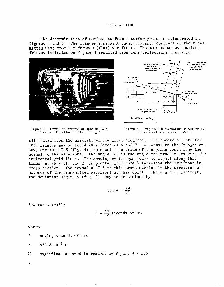
The determinat ion o f dev ia t ions from in te r fe rograms i s i l l u s t r a t e d i n f i g u r e s 4 and 5 . mi t ted wave from a r e fe rence ( f l a t ) wavefront. The more numerous spur ious f r i n g e s i n d i c a t e d on f i g u r e 4 r e s u l t e d from l ens r e f l e c t i o n s t h a t were
The f r i n g e s r ep resen t equal d i s t a n c e contours of t he t r a n s -
Normal lo Ironsmilled wmefronl (Olrecllon Of
transmilled lighl (x dernaled my)
Normal lo reference ifloll w.Yefro"l
lhrough aperlure C-3
Width of aperture C-3 01 gloss surface
\ ..
Reference wavefront
Figure 4.- Normal to fringes at aperture C-3 indicating direction of line of sight.
Figure 5.- Graphical construction of wavefront cross section at aperture C-3.
e l imina ted from t h e a i r c ra f t window in te r fe rograms. The theory of i n t e r f e r - ence f r i n g e s may be found i n re ferences 6 and 7. A normal t o t h e f r inges a t , s ay , ape r tu re C-3 ( f i g . 4) r ep resen t s t h e t r a c e of t h e p lane conta in ing t h e normal t o t h e wavefront . The angle I$ i s t h e angle t h e t r a c e makes wi th t h e ho r i zon ta l g r i d l i n e s . The spac ing of f r i n g e s (dark t o l i g h t ) a long t h i s trace a, (b + c ) , and d as p l o t t e d i n f i g u r e 5 r e c r e a t e s t h e wavefront i n c ross s e c t i o n . The normal a t C-3 t o t h i s cross s e c t i o n i s t h e d i r e c t i o n of advance of t h e t r ansmi t t ed wavefront a t t h i s p o i n t . The angle of i n t e r e s t , t he dev ia t ion angle 6 ( f i g . 2 ) , may be determined by:
AM t a n 6 = - LR
f o r small angles
AM LR 6 2 - seconds of arc
where
6 angle , seconds of a r c
A 6 3 2 . 8 ~ 1 0 ~ ~ m
M magni f ica t ion used i n readout of f i g u r e 4 = 1 . 7
6

L length ( f i g . 5) = 0.04115 m
R rad ians p e r second of arc = 4 . 8 4 8 ~ 1 0 - ~
6 = 632*8x10-9x1'7 = 5.4 seconds of arc 4 . 8 4 8 ~ 1 0 - ~ ~ 0 . 0 4 1 1 5
The p r e c i s i o n o f t h i s g raph ica l technique of in te r fe rogram i n t e r p r e t a t i o n depends on t h e p r e c i s i o n o f t h e inpu t s i n t o t h e l i n e a r equat ion used above f o r computing dev ia t ions . determine angular dev ia t ion of s e v e r a l ape r tu re s was performed wi th a l l e r r o r sources included i n t h e measurements. Thus, a normal was e r e c t e d t o t h e f r i n g e s a t an a p e r t u r e of i n t e r e s t , measurements were made of f r i n g e spac ings , a p l o t was made, a normal was e r e c t e d t o t h e wavefront p r o f i l e thus p l o t t e d , "L" was measured, and t h e angle 6 was computed. This procedure w a s repea ted seve ra l times a t each a p e r t u r e . Less than 1 second of arc d i f f e r e n c e i n dev ia t ion was noted a t any a p e r t u r e . r epea tab le t o 1' f o r l a r g e dev ia t ion f r i n g e s . The components Aa and A B i n f i g u r e 2 of t h e devia ted ray 6 l i e along t h e h o r i z o n t a l and v e r t i c a l g r i d l i n e s of f i g u r e 4 and can b e computed, provided 6 and 4 a r e known. An unce r t a in ty of 1' i n $I w i l l cause e r r o r s of l e s s than 1 second of a r c i n the h o r i z o n t a l and v e r t i c a l components of dev ia t ion f o r a l l values of 6 l e s s than 59 seconds of arc. A l l values of 6 were we l l below t h i s . I n t h e in s t ances of small dev ia t ion , where f r i n g e s were few and it was d i f f i c u l t t o r epea t t h e 0 measurement t o lo, t h e t o t a l dev ia t ion was s o low t h a t t h e components of dev ia t ion were w e l l below 1 second of arc.
R e p e t i t i v e i n t e r p r e t a t i o n of t h e in te r fe rogram t o
The angle o f t h e t r a c e p lane w a s
When many ape r tu re s ac ross a t r a n s m i t t e d wavefront in te r fe rogram must be analyzed f o r dev ia t ions , a computational method, such as descr ibed i n r e f e r - ence 8, would prove t o be u s e f u l . r e p o r t , a window s u r f a c e model i s descr ibed t h a t y i e l d s a three-dimensional , l eas t - squares , polynomial approximation t o t h e s u r f a c e . The procedure could be used t o approximate t h e s u r f a c e o f t h e t r ansmi t t ed wave of t h i s s tudy . The u n i t vec to r normal t o t h e s u r f a c e a t a given p o i n t could then be obta ined by computation and would y i e l d t h e dev ia t ion i n seconds of arc from t h e o r i g i n a l ( re ference) u n i t vec to r . This was no t done i n t h e s tudy because of t h e l imi t ed number of ape r tu re s t e s t e d , b u t t h e a p p l i c a t i o n would be s t r a i g h t f om ard .
I n t h e computational procedures of t h a t
A t r ansmi t t ed wave in te r fe rogram, such as f i g u r e 6 ( b ) , could be i n d i c a t i v e of e i t h e r a d iverg ing o r a converging wavefront. t i c a l rod and b a l l i n f i g u r e 6 is t h e suppor t f o r p a r t of t h e l i g h t source . ) This ambiguity can b e reso lved by a second in te r fe rogram taken as i n f i g - u r e 6(a) o r 6 ( c ) . The movement of t h e tangent s p o t of f i g u r e 6(b) ( c losed f r i n g e t o t h e l e f t o f cen te r ) with r o t a t i o n of t h e r e fe rence wavefront i s t h e c lue t o t h e n a t u r e o f t h e wavefront, as simply por t rayed i n t h e l i n e diagram t o the r i g h t o f t h e photographs. Both f i g u r e s 6(a) and (c) i l l u s t r a t e t h e s p o t motion f o r a convex wavefront. The s p o t motion would be oppos i te i f t h e
(The dark ver-
7

Tangent spot
(a) Counterclockwise rotation of reference wavefront.
propagat ion
(b) Zero order.
(c) Clockwise rotation of reference wavefront.
Figure 6.- Determination of convex wavefront.
wavefront were converging. Thus, a s tudy of movement of t h e tangent spo t as one of t h e Mach-Zender in t e r f e romete r mi r ro r s i s r o t a t e d wi th a thumbscrew revea l s t h e n a t u r e of t h e wavefront.
RESULTS
The f i rs t s t e p of t h e o b j e c t i v e s , ob ta in ing in te r fe rograms of a wavefront t ransmiss ion through a window under environmental cond i t ions , was accom- p l i s h e d as can b e seen i n f i g u r e s 4 , 6 , 8, 10, and 11, which were some of those obta ined dur ing t h e i n v e s t i g a t i o n . These f i g u r e s a r e evidence of t h e suc- c e s s f u l adap ta t ion of l a rge ape r tu re (12 inch) i n t e r f e r o m e t e r components t o long o p t i c a l pa th lengths (over 100 f t ) t o o b t a i n in te r fe rograms.
The technique used i n t h e procedure showed t h a t t h e in te r fe rogram rep resen t s t h e d i s t o r t i o n t o a f l a t wavefront caused by t h e window. The i n i t i a l adjustment , wi th t h e window out of t h e in t e r f e romete r pa th , gave a f i e l d devoid of f r i n g e s . With i n s e r t i o n of t h e win- dow, t h e f r i n g e s appeared as i n t h e above photographs, and t h e usual i n t e r -
p r e t a t i o n of t h e f r i n g e s could be made from t h e number and curva ture , which a r e i n d i c a t i v e of s p h e r i c i t y of t h e new wavefront. The f r i n g e l i n e s , as i n t h e c ross s e c t i o n of f i g u r e 5 , reproduce t h e three-dimensional wavefront i n two dimensions. Figure 5 i n d i c a t e s t h a t t h e d i r e c t i o n o f any devia ted r ay a t a po in t i s normal t o such a wavefront a t t h a t p o i n t .
Using t h e in te r fe rograms and cons t ruc t ing c ros s s e c t i o n s , such as f i g u r e s 4 and 5, and t h e formula f o r t a n 6 i n t he procedures , d i d y i e l d devia t ions i n seconds of arc. Thus, t h e concept o f d e r i v i n g devia t ions of a l i n e of s i g h t from in te r fe rograms was demonstrated.
The main purpose o f t h e s tudy w a s t o show t h a t i n t e r f e r o m e t r i c devia- t i o n s a r e p r e c i s e enough t o c o r r e c t window dev ia t ion e r r o r s . The fol lowing r e s u l t s a r e poin ted out t o demonstrate t h a t t h i s was t r u e .
1. The angular dev ia t ions through t h e s p a c e c r a f t windows with the d i r e c t dev ia t ion measurement system a t 15' inc idence are p l o t t e d i n f i g u r e 7. The r e s u l t s , by i n t e r f e r o m e t r i c i n t e r p r e t a t i o n of f i g u r e 8 , agree very well with t h e d i r e c t measurements ( t o wi th in 1 second of a r c ) . The i n t e r f e r e n c e
8

(a) Deviation in plane of incidence for apertures in horizontal ccnterline.
"? T g 10-
(b) Deviations perpendicular to plane of incidence for apertures in horizontal centerline.
m 0 I I I I I I I
- 1 % I 3 2 I 0 -I -2 -3 -I4
(c) Deviations in plane of incidence for apertures in vertical centerline.
m VI
- 0
" I O -
6 0 ) 1 +e j 01
>
O - ) O L I I I I11 I I I 5 4 3 2 I O - 1 - 2 - 3 - 4
Aperture location, in.
(d) Deviations perpendicular to plane of incidence for apertures in vertical centerline.
Figure 7 . - Line-of-sight angular deviations through a spacecraft window at 15" incidence.
Figure 8.- Transmitted wave of spacecraft window at 15' incidence.
measurements were made by i n t e r p r e t a - t i o n of t h e t r ansmi t t ed wave i n t e r - ferogram shown i n f i g u r e 8 where t h e l i ne -o f - s igh t dev ia t ion f r i n g e s a r e t h e l a r g e ragged dark a reas as noted .
2 . With an inc rease i n angle of incidence t o 45" degrees , t h e agreement of d i r e c t measurement d a t a with d a t a obta ined by i n t e r p r e t a t i o n of t h e i n t e r - ferogram w a s w i t h i n 2 seconds of a r c as shown i n t h e d a t a p l o t s of f i g u r e 9 . The corresponding in te r fe rogram ( f i g . 10) shows an inc rease i n f r i n g e s wi th t h i s h ighe r inc idence . 1 2 seconds of arc.
The maximum measured dev ia t ion increased t o
3 . The a i r c ra f t window, as can be seen from t h e in te r fe rogram of f i g u r e 11, has a high q u a l i t y o p t i c a l a r e a c e n t r a l l y loca t ed , and moderate q u a l i t y otherwise. The dev ia t ions reached a maximum of 34 seconds as p l o t t e d i n f i g u r e 1 2 . Again, t h e f i g u r e shows t h a t t h e i n t e r f e r o m e t r i c dev ia t ions p r a c t i c a l l y superimposed on t h e measured va lue and t h e g r e a t e s t d i f f e r e n c e w a s only 2 seconds o f arc. The l - inch-diameter a p e r t u r e centered a t g r i d i n t e r - s e c t i o n ( c , 2 - 1 / 2 i n . ) o f f i g u r e 11, i s h a l f on t h e high q u a l i t y c e n t r a l por- t i o n of t h e window and h a l f on t h e moderate q u a l i t y p o r t i o n . t h e image observed by t h e d i r e c t measurement technique revea led t h i s discon- t i n u i t y i n t h e t r ansmi t t ed wave; t h e r e f o r e , s e p a r a t e devia t ions were measured f o r each h a l f o f t h e ape r tu re . The i n t e r f e r o m e t r i c d a t a e x t r a c t e d from each h a l f of t h i s a p e r t u r e agreed c l o s e l y (wi th in 2 sec) with t h e measured d a t a .
D i s t o r t i o n of
9
I

T 10- 0 Direct measurement 0 Interferometer
8
IF1 I 2 I 01 r
(3 5
.- & 5 08
I l l 1 0"
I Y 1 , I I I -20: -4 I -3 ' -2 I - I I 0 I 2 3 4
T
in I I I 8'
I l l 1
(a) Deviation in plane of incidence for apertures in horizontal centerline.
8 .; ._ l ' ; y t I + O y l
-10 L 5 4 3 2 I O - I - 2 - 3 - 4
(c) Deviations in plane of incidence for apertures i n vertical centerline.
Figure 10.- Transmitted wave of spacecraft window T at 45" incidence. " 10- I
- 6 01 I I Q I nl -I
-I0," A 3 2 I -I -2 - 3 -4
I n I R I 0 > I
0" .-
40 - o D I E ~ ~ measurement
3o - 0 Interferometer El I l l I l l 1
Aperture locotion. in.
(d) Deviations perpendicular to plane of incidence 20 f o r aDertures in vertical centerline. t "
2 10- c q 0 8 I l l I I I I I I I
Figure 9.- Line-of-sight angular deviations through 0 I I I I I I I 0 ol-, 5 -10 -
a spacecraft window at 45" incidence. 0 n
0
El -20 -
-30 -
- 4 0 L I I I I I 1 1 1 I I I I I I - 7 -6 -5 -4 -3 -2 -I 0 I 2 3 4 5 6 7
(a) Deviations in plane o f incidence for apertures in row C .
.-
R O 0 0 5 -10 - n
- L I I I I I I 1 1 1 0 I " I I I I *'-7 -6 -5 -4 -3 -2 -I 0 I 2 3 4 5 6 7
Aperture location, in.
(b) Deviations perpendicular to plane of incidence for apertures in row C.
Figure 12.- Line-of-sight angular deviations through an aircraft window at 45' incidence.
Figure 11.- Transmitted wave o f aircraft window at 45" incidence.
10

D
F 8 - e al
g 4 -
01 - 5
50 -
40 -
30 -
2 0 - I
6 l 0 - - 0
O F
-10 -
-20 -
(a) Wavefront profile.
7
I T I 7
Horizontol location in wavefront. in.
(b) Slope of wavefront profile.
Figure 13.- Wavefront profile and its slope at row B of aircraft window for 45' incidence in plane of row B.
40 - o Direct meosurement
I 10- I ;'n';;;, ~ 1 ; lgl 8/ y 1 , t I I I I I I I
0 g 0 ;
5 -10 - 0
- 2 0 - -30 -
E l e n - 4 O L I I I I I I
-7 -6 -5 -4 -3 -2 -I 0 I 2 3 4 5 6 7 Aperture locotion. in.
Figure 14.- Line-of-sight angular deviations in the plane of incidence f o r apertures in row B of aircraft window at 45" incidence.
4. I n f i g u r e 11, it can b e seen t h a t t h e dev ia t ions i n row B w i l l l i e p r i n c i p a l l y i n t h e h o r i z o n t a l p l ane of which B i s t h e t r a c e . Because of t h i s coincidence, t h e complete p r o f i l e of t h e wavefront a long row B was p l o t t e d i n f i g u r e 13 (a ) . The f a i r l y f l a t c e n t r a l p o r t i o n and t h e s t e e p s lope on e i t h e r s i d e can be noted . The angular dev ia t ion i s t h e f i r s t d e r i v a t i v e o r s lope of t h i s p r o f i l e . u r e 13(b) . The i r r e g u l a r i t i e s of t h e s lope r ep resen t a c t u a l devia t ions of t h e l i n e o f s i g h t . I n o rde r t o v e r i f y t h e d a t a of f i g u r e 13, t h e mean dev ia t ion f o r ape r tu re s a long row B was p l o t t e d i n f i g - u re 14, a long with devia t ions obta ined wi th t h e d i r e c t measurement apparatus . The measured and i n t e r f e r o m e t r i c d a t a agree i n a l l cases t o wi th in 2 seconds of arc.
This has been p l o t t e d i n f i g -
As a measure of t h e d i f f e r e n c e between t h e i n t e r f e r o m e t r i c d a t a and t h e measured da ta , t h e s tandard dev ia t ion o f a l l t h e s e d i f f e rences f o r t h e a i r - c r a f t window d a t a was only 0 . 7 second of a r c , whi le t h a t f o r t h e s p a c e c r a f t window was j u s t 0 .6 second of a r c .
U t i l i z a t i o n o f i n t e r f e r e n c e f r i n g e s f o r determining wavefront s lope leads t o cons ide ra t ion of Moir6 f r i n g e s o f t h e t r ansmi t t ed wave t h a t would reveal p a t t e r n s o f cons tan t s lope , which, i n t u r n , would correspond t o p a t t e r n s of cons tan t angular dev ia t ions . Reference 9 touches on t h i s s u b j e c t of wavefront mapping by dual i n t e r f e romet ry , and a l s o shows what a Moir6 f r i n g e p a t t e r n i s and what i t r e v e a l s . Moir6 p a t t e r n s were obta ined as p a r t of t h i s s tudy , b u t t h e s p a c e c r a f t window had s o f e w f r i n g e s t h a t t h e Moirg p a t t e r n was i n d i s t i n c t , and t h e graphica l technique on a s i n g l e in te r fe rogram proved t o be a more s e n s i t i v e d a t a r educ t ion method. The dual i n t e r f e romete r a l s o r equ i r ed a f i x e d known wedge b i a s on both in t e r f e romete r s i n known planes t o keep t h e Moir6 p a t t e r n s lopes r e l a t i v e t o t h e window a x i s . This
11
I

compounded t h e d a t a a c q u i s i t i o n problem. Thus i t was concluded t h a t t h e Moire p a t t e r n approach was unacceptable f o r h igh o p t i c a l q u a l i t y windows, and it was given no f u r t h e r cons ide ra t ion i n t h i s s tudy .
CONCLUSIONS
The a n a l y s i s of t h e in te r fe rograms as de r ived i n t h e procedure proved t o b e a t rus twor thy and p r a c t i c a l means f o r ob ta in ing t h e dev ia t ions i n seconds of a r c , The i n t e r f e r o m e t r i c method is p a r t i c u l a r l y convenient because an i n t e r f e r e n c e photograph f o r a given tes t condi t ion o f inc idence angle and p lane of inc idence y i e l d s e r r o r s f o r a l l a p e r t u r e s . The i n t e r f e r e n c e p a t t e r n must a l s o be i n t e r r o g a t e d as i n f i g u r e 6 t o determine t h e type of wavefront ( i . e . , converging o r diverging) t o ob ta in t h e c o r r e c t d i r e c t i o n of dev ia t ion .
The p r e c i s i o n ob ta inab le wi th in t e r f e romet ry i s e x c e l l e n t f o r determin- ing angular dev ia t ions through a window. d i f f e rence between i n t e r f e r o m e t e r d a t a and p r e c i s e d i r e c t l y measured d a t a was 0 . 7 second of arc f o r t h e 129 measurements of t h i s i n v e s t i g a t i o n . The range of dev ia t ions i n v e s t i g a t e d - a few seconds t o about 40 seconds - includes those of i n t e r e s t f o r nav iga t iona l measurements i n both spacec ra f t and a i r c ra f t .
The s t anda rd dev ia t ion of t h e
Any conclusion on t h e r e l a t i v e mer i t o f computed dev ia t ions versus i n t e r f e r o m e t r i c d a t a must be based on how v a l i d t h e assumed boundary condi- t i o n s are and on how r e l i a b l e t h e g l a s s c h a r a c t e r i s t i c s of wedge, f l a t - nes s , e t c . , a r e f o r t h e computational approach when ba lanced aga ins t t h e d i f f i - c u l t i e s of ob ta in ing t h e necessary in te r fe rograms. The i n t e r f e r o m e t r i c experimental d a t a , having a l l t h e anomalies of g l a s s , frame, s h e l l mounting, p re s su re deformation, e t c . included i n a t r a n s m i t t e d wavefront , e l imina ted any e r r o r of omission o r u n c e r t a i n t y .
The in t e r f e romet ry method l i m i t s the d a t a t o t h e p a r t i c u l a r angle of incidence and p lane o f inc idence of t h e l i g h t e n t e r i n g t h e window. s e p a r a t e in te r fe rogram i s r equ i r ed f o r each of t h e s e parameter changes.
Thus, a
Deviat ion measurement systems, us ing e i t h e r an au tocol l imator o r an i n t e r f e r o m e t r i c system, a r e faced with p a r t i c u l a r problems inherent i n a t es t window, such as t h e dup l i ca t ion of environmental p r e s s u r e , e f f e c t s of t h e veh ic l e s h e l l on t h e window mounting, and movement of t h e window o r measure- ment apparatus t o produce angles of incidence and p l anes of incidence of i n t e r e s t . The problems a s soc ia t ed with mounting an au toco l l ima to r o r i n t e r - ferometer ad jo in ing a window of a spacec ra f t o r a i r c r a f t a r e seve re , p a r t i c u - l a r l y wi th regard t o v i b r a t i o n and a i r movement. i n t e r f e r o m e t r i c system i s dependent on t h e a b i l i t y t o adapt i n t e r f e r o m e t r i c equipment more r e a d i l y than t h e au tocol l imator t o s o l v e t h e s e problems.
The f e a s i b i l i t y of t h e
This
1 2

s tudy , while it d i d no t a t t ack a l l t he p r a c t i c a l problems involved, d i d prove t h a t i n t e r f e r o m e t r i c equipment i s adaptable and has c e r t a i n advantages over t h e au tocol l imator method.
Ames Research Center Nat ional Aeronautics and Space Adminis t ra t ion
Moffett F i e l d , C a l i f . 94035, June 3, 1969
REFERENCES
1. Smith, Donald W . ; and Lampkin, Bedford A . : Sextant S igh t ing Measurements From On Board t h e Gemini X I 1 Spacec ra f t . NASA TN D-4952, 1968.
2 . Acken, Richard A . ; and Smith, Donald W . : Navigator Performance Studies f o r Space Navigation Using the NASA CV-990 Research Aircraf t . NASA TN D-4449, 1968.
3. Warner, David N . , J r . ; and Walsh, Thomas M . : E f f e c t s of Edge Cons t ra in ts on Opt ica l Q u a l i t i e s of a Spacecraf t Window. NASA TN D-4845, 1968.
4 . Ashton, A . ; and Marchant, A . C . : Note on Tes t ing of Large Glass Panels . Optica Acta, v o l . 14, no. 2 , 1967, pp. 203-204.
5 . Dyson, J . : Optics i n a H o s t i l e Environment. Applied Opt ics , v o l . 7, no. 4 , Apr i l 1968, pp. 569-580.
6 . S t e e l , W . H . : Interferometry. Univers i ty P res s , Cambridge, London, 1967.
7. Candler, C . : Modem Interferometers. Hi lge r and Watts, Ltd. , London, H i lge r Div is ion , 1951.
8. White, Kenneth C . ; and Gadeberg, Burnet t L . : Methods f o r P r e d i c t i n g Spacecraft-Window- Induced Line- of -Sight Devi a t ions . 1969.
NASA TN D- 5238,
9 . Langenbeck, P . : Opt ica l Wave-Front Mapping by Dual In te r fe rometry . JOSA, v o l . 58, no. 4, Apr i l 1968, pp. 499-505.
NASA-Langley, 1970 - 23 A-3074 13
I