interference mitigation by mimo cooperation and …srif2012.inc.cuhk.edu.hk/slides/vincent...
TRANSCRIPT
Interference Mitigation by MIMO Cooperation and Coordination - Theory and Implementation Challenges
Vincent Lau Dept of ECE,
Hong Kong University of Science and Technology

Background
2
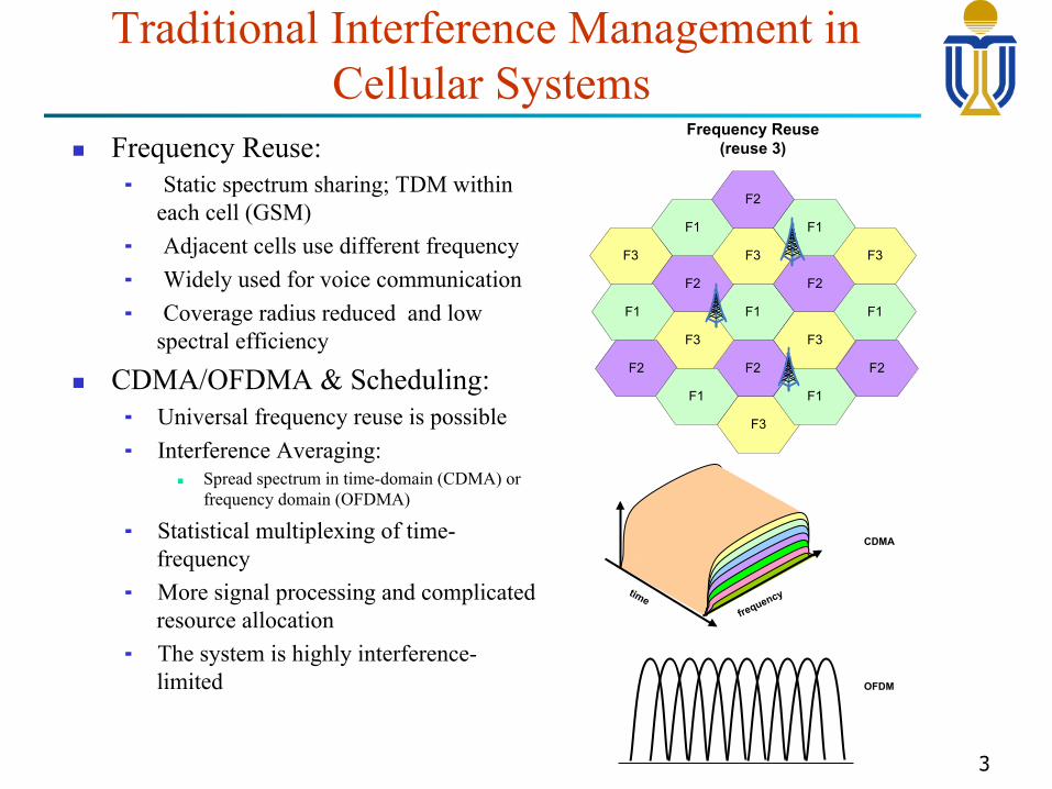
Traditional Interference Management in Cellular Systems
n Frequency Reuse: ¬ Static spectrum sharing; TDM within
each cell (GSM) ¬ Adjacent cells use different frequency ¬ Widely used for voice communication ¬ Coverage radius reduced and low
spectral efficiency
n CDMA/OFDMA & Scheduling: ¬ Universal frequency reuse is possible ¬ Interference Averaging:
n Spread spectrum in time-domain (CDMA) or frequency domain (OFDMA)
¬ Statistical multiplexing of time-frequency
¬ More signal processing and complicated resource allocation
¬ The system is highly interference-limited
3
F1
F3
F2
F2
F3
F2
F3
F1
F3
F1
F2
F1
F2
F1
F3
F1
F1
F3
F2
Frequency Reuse(reuse 3)
CDMA
OFDM
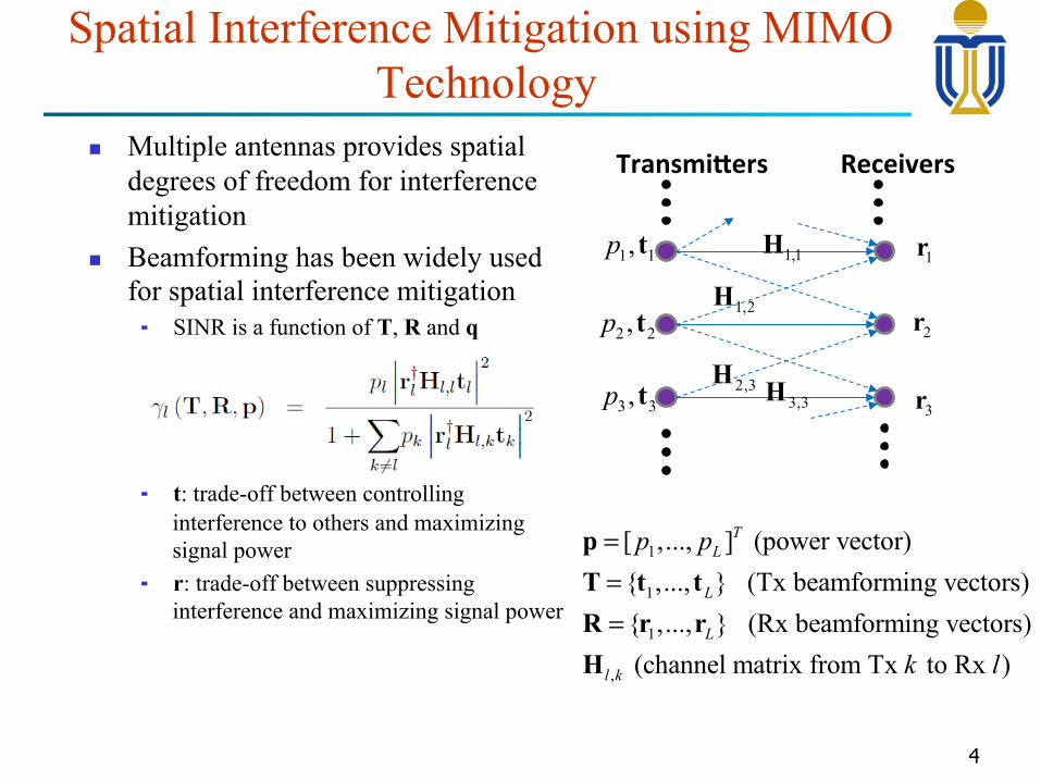
Spatial Interference Mitigation using MIMO Technology
n Multiple antennas provides spatial degrees of freedom for interference mitigation
n Beamforming has been widely used for spatial interference mitigation ¬ SINR is a function of T, R and q
¬ t: trade-off between controlling interference to others and maximizing signal power
¬ r: trade-off between suppressing interference and maximizing signal power
4
Transmi(ers Receivers
1,1H
1,2H
2,3H3,3H
1 1,p t
2 2,p t
3 3,p t
1r
2r
3r
1
1
1
,
[ ,..., ] (power vector) { ,..., } (Tx beamforming vectors) { ,..., } (Rx beamforming vectors) (channel matrix from Tx to Rx )
TL
L
L
l k
p p
k l
===
pT t tR r rH
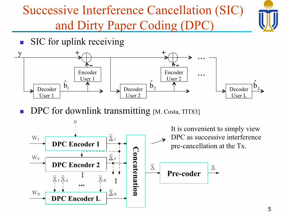
Successive Interference Cancellation (SIC) and Dirty Paper Coding (DPC)
n SIC for uplink receiving
n DPC for downlink transmitting [M. Costa, TIT83]
5
Decoder User 1
Encoder User 1
Decoder User 2
Encoder User 2
-+
-+
Decoder User L
…
…
y
1b̂ 2b̂ b̂L
DPC Encoder 1
DPC Encoder 2
DPC Encoder L
Concatenation
Pre-coder
It is convenient to simply view DPC as successive interference pre-cancellation at the Tx.
Achievements and Limitations of Existing Interference Mitigation Technologies
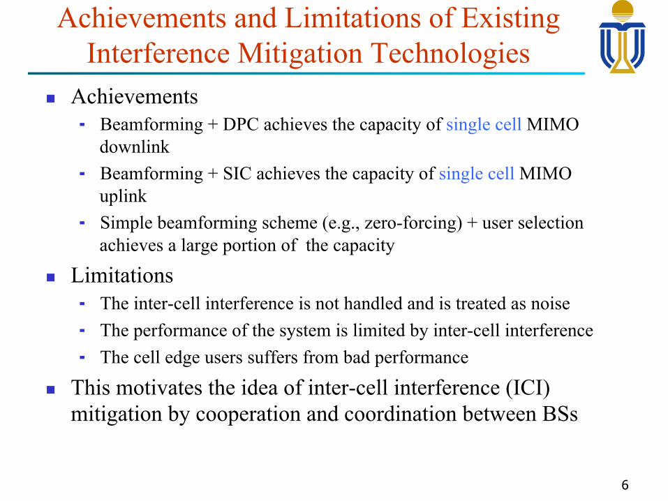
n Achievements ¬ Beamforming + DPC achieves the capacity of single cell MIMO
downlink ¬ Beamforming + SIC achieves the capacity of single cell MIMO
uplink ¬ Simple beamforming scheme (e.g., zero-forcing) + user selection
achieves a large portion of the capacity
n Limitations ¬ The inter-cell interference is not handled and is treated as noise ¬ The performance of the system is limited by inter-cell interference ¬ The cell edge users suffers from bad performance
n This motivates the idea of inter-cell interference (ICI) mitigation by cooperation and coordination between BSs
6
Theory of Co-MIMO
7
Joint processing
I
I
I
I
I
I
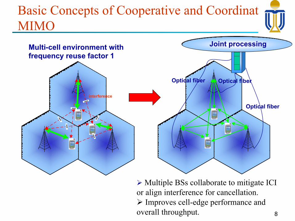
Ø Multiple BSs collaborate to mitigate ICI or align interference for cancellation. Ø Improves cell-edge performance and overall throughput.
Multi-cell environment with frequency reuse factor 1
Optical fiber
Optical fiber Optical fiber
interference
Basic Concepts of Cooperative and Coordinative MIMO
8

(1) Cooperative Zero-Forcing Beamforming (ZFBF)
2h1h
1e
2e
1 1g t The direction of the projection gives transmitter vector, while the norm square of the projection gives the equivalent channel
The mutual interfering multi-user channel is decomposed into multiple parallel independent SISO channels:
T1
R2 T2
R1
21 1 1g = h t
22 2 2g = h t
The optimal power allocation is easy, e.g., Water-filling is optimal for sum rate maximization with sum power constraint
9
ZFBF on a Larger dimension Signal Space à achieve full DoF
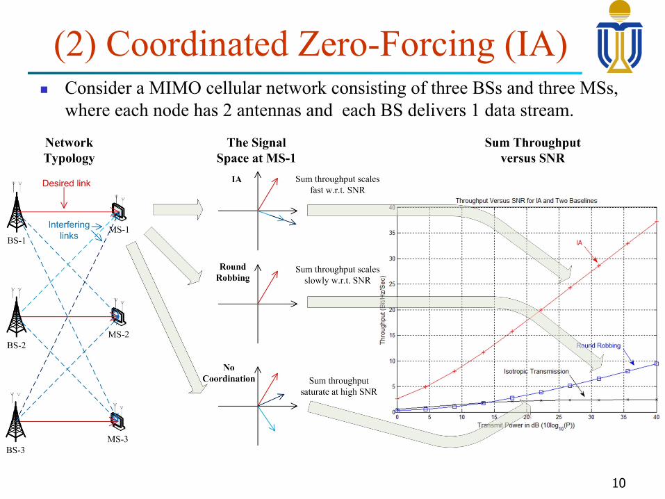
(2) Coordinated Zero-Forcing (IA) n Consider a MIMO cellular network consisting of three BSs and three MSs,
where each node has 2 antennas and each BS delivers 1 data stream.
10
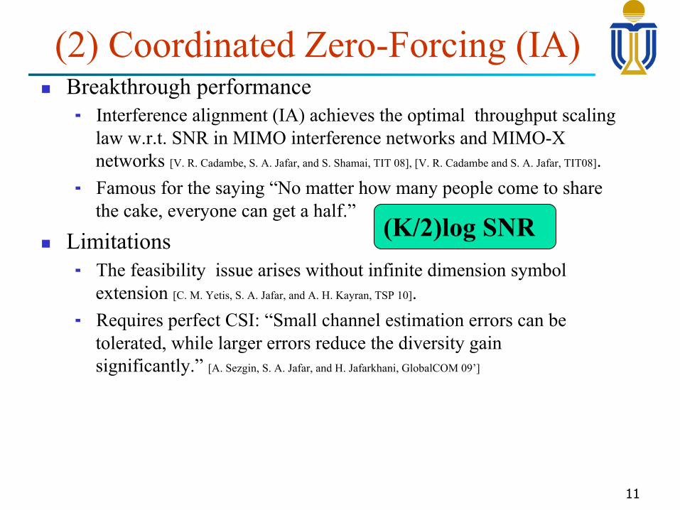
(2) Coordinated Zero-Forcing (IA) n Breakthrough performance
¬ Interference alignment (IA) achieves the optimal throughput scaling law w.r.t. SNR in MIMO interference networks and MIMO-X networks [V. R. Cadambe, S. A. Jafar, and S. Shamai, TIT 08], [V. R. Cadambe and S. A. Jafar, TIT08].
¬ Famous for the saying “No matter how many people come to share the cake, everyone can get a half.”
n Limitations ¬ The feasibility issue arises without infinite dimension symbol
extension [C. M. Yetis, S. A. Jafar, and A. H. Kayran, TSP 10]. ¬ Requires perfect CSI: “Small channel estimation errors can be
tolerated, while larger errors reduce the diversity gain significantly.” [A. Sezgin, S. A. Jafar, and H. Jafarkhani, GlobalCOM 09’]
11
(K/2)log SNR
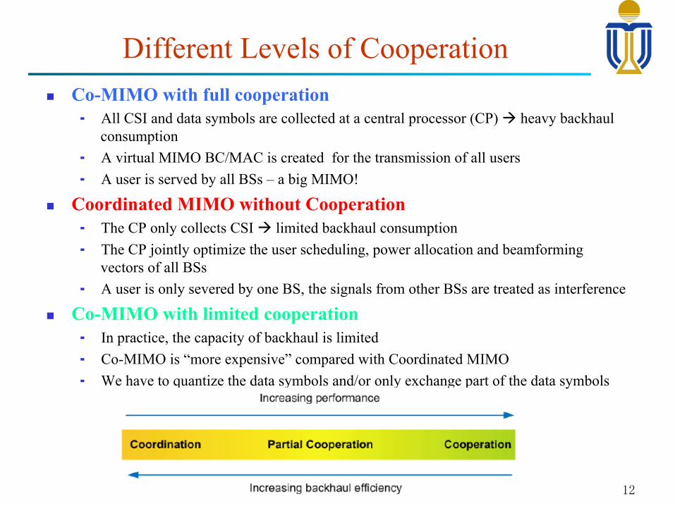
n Co-MIMO with full cooperation ¬ All CSI and data symbols are collected at a central processor (CP) à heavy backhaul
consumption ¬ A virtual MIMO BC/MAC is created for the transmission of all users ¬ A user is served by all BSs – a big MIMO!
n Coordinated MIMO without Cooperation ¬ The CP only collects CSI à limited backhaul consumption ¬ The CP jointly optimize the user scheduling, power allocation and beamforming
vectors of all BSs ¬ A user is only severed by one BS, the signals from other BSs are treated as interference
n Co-MIMO with limited cooperation ¬ In practice, the capacity of backhaul is limited ¬ Co-MIMO is “more expensive” compared with Coordinated MIMO ¬ We have to quantize the data symbols and/or only exchange part of the data symbols
Different Levels of Cooperation
12
Standardization in LTE
13
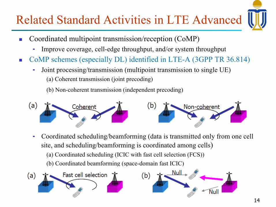
Related Standard Activities in LTE Advanced n Coordinated multipoint transmission/reception (CoMP)
¬ Improve coverage, cell-edge throughput, and/or system throughput n CoMP schemes (especially DL) identified in LTE-A (3GPP TR 36.814)
¬ Joint processing/transmission (multipoint transmission to single UE) (a) Coherent transmission (joint precoding)
(b) Non-coherent transmission (independent precoding)
¬ Coordinated scheduling/beamforming (data is transmitted only from one cell site, and scheduling/beamforming is coordinated among cells)
(a) Coordinated scheduling (ICIC with fast cell selection (FCS)) (b) Coordinated beamforming (space-domain fast ICIC)
14
Practical Challenges and Issues
15
n Backhaul constraint ¬ Backhaul latency ¬ Capacity constraints
n CSI Acquisition n Synchronization
¬ Timing Sync ¬ Frequency offsets Sync
Practical Challenges and Issues
16
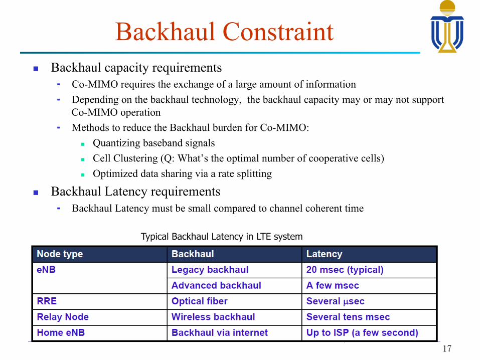
n Backhaul capacity requirements ¬ Co-MIMO requires the exchange of a large amount of information ¬ Depending on the backhaul technology, the backhaul capacity may or may not support
Co-MIMO operation ¬ Methods to reduce the Backhaul burden for Co-MIMO:
n Quantizing baseband signals n Cell Clustering (Q: What’s the optimal number of cooperative cells) n Optimized data sharing via a rate splitting
n Backhaul Latency requirements ¬ Backhaul Latency must be small compared to channel coherent time
Backhaul Constraint
17
Typical Backhaul Latency in LTE system
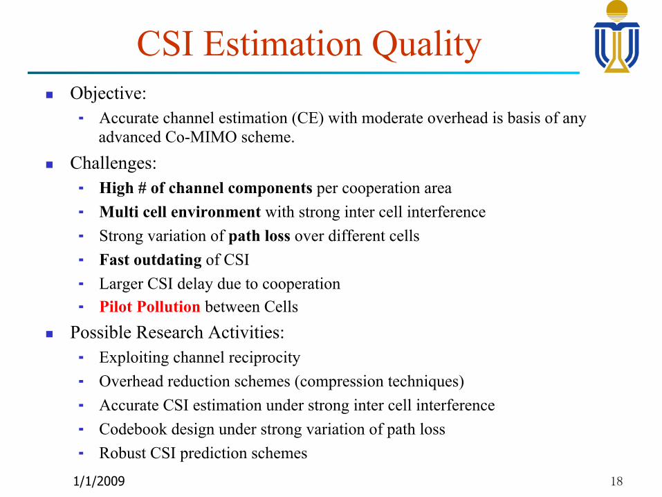
n Objective: ¬ Accurate channel estimation (CE) with moderate overhead is basis of any
advanced Co-MIMO scheme. n Challenges:
¬ High # of channel components per cooperation area ¬ Multi cell environment with strong inter cell interference ¬ Strong variation of path loss over different cells ¬ Fast outdating of CSI ¬ Larger CSI delay due to cooperation ¬ Pilot Pollution between Cells
n Possible Research Activities: ¬ Exploiting channel reciprocity ¬ Overhead reduction schemes (compression techniques) ¬ Accurate CSI estimation under strong inter cell interference ¬ Codebook design under strong variation of path loss ¬ Robust CSI prediction schemes
CSI Estimation Quality
1/1/2009 18
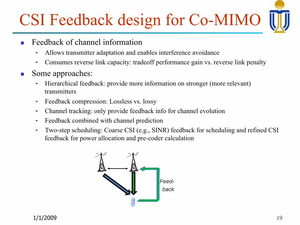
n Feedback of channel information ¬ Allows transmitter adaptation and enables interference avoidance ¬ Consumes reverse link capacity: tradeoff performance gain vs. reverse link penalty
n Some approaches: ¬ Hierarchical feedback: provide more information on stronger (more relevant)
transmitters ¬ Feedback compression: Lossless vs. lossy ¬ Channel tracking: only provide feedback info for channel evolution ¬ Feedback combined with channel prediction ¬ Two-step scheduling: Coarse CSI (e.g., SINR) feedback for scheduling and refined CSI
feedback for power allocation and pre-coder calculation
CSI Feedback design for Co-MIMO
1/1/2009 19
n For Co-MIMO, the transmission from multiple BSs must be synchronized. ¬ OFDM with CP allows some margins in timing sync. ¬ However, large distances between the base stations result in large timing
offsets which may exceed CP length and lead to inter-symbol interference n Sync using primary clock reference
¬ Primary clock boards of cooperative BSs is synchronized to a common external reference clock
¬ Commercial Rubidium- and crystal-based reference clocks can be phase-locked to the GPS.
n Network synchronization ¬ Suitable for indoor BSs where GPS signal may be blocked ¬ Precise timing protocol (PTP) specified in IEEE 1588 standard is a good
candidate ¬ Packet delay spread must be kept small to achieve high accuracy of timing
sync: give higher priority for PTP packets
Timing Synchronization
20
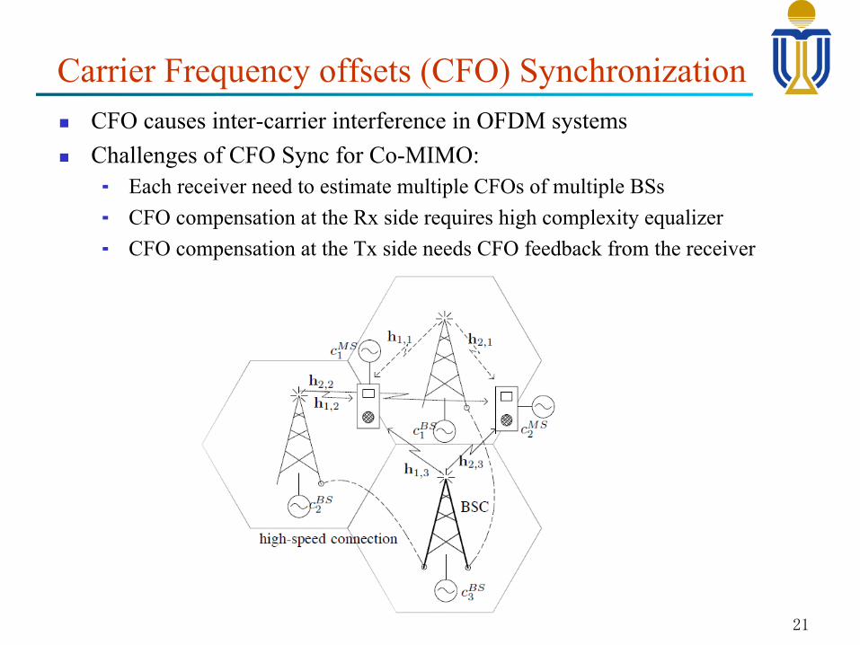
n CFO causes inter-carrier interference in OFDM systems n Challenges of CFO Sync for Co-MIMO:
¬ Each receiver need to estimate multiple CFOs of multiple BSs ¬ CFO compensation at the Rx side requires high complexity equalizer ¬ CFO compensation at the Tx side needs CFO feedback from the receiver
Carrier Frequency offsets (CFO) Synchronization
21
Performance under Practical Constraints
22
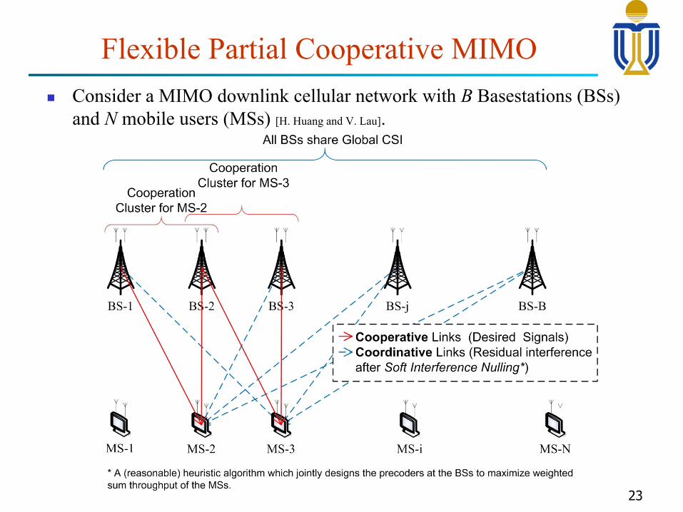
Flexible Partial Cooperative MIMO n Consider a MIMO downlink cellular network with B Basestations (BSs)
and N mobile users (MSs) [H. Huang and V. Lau].
23
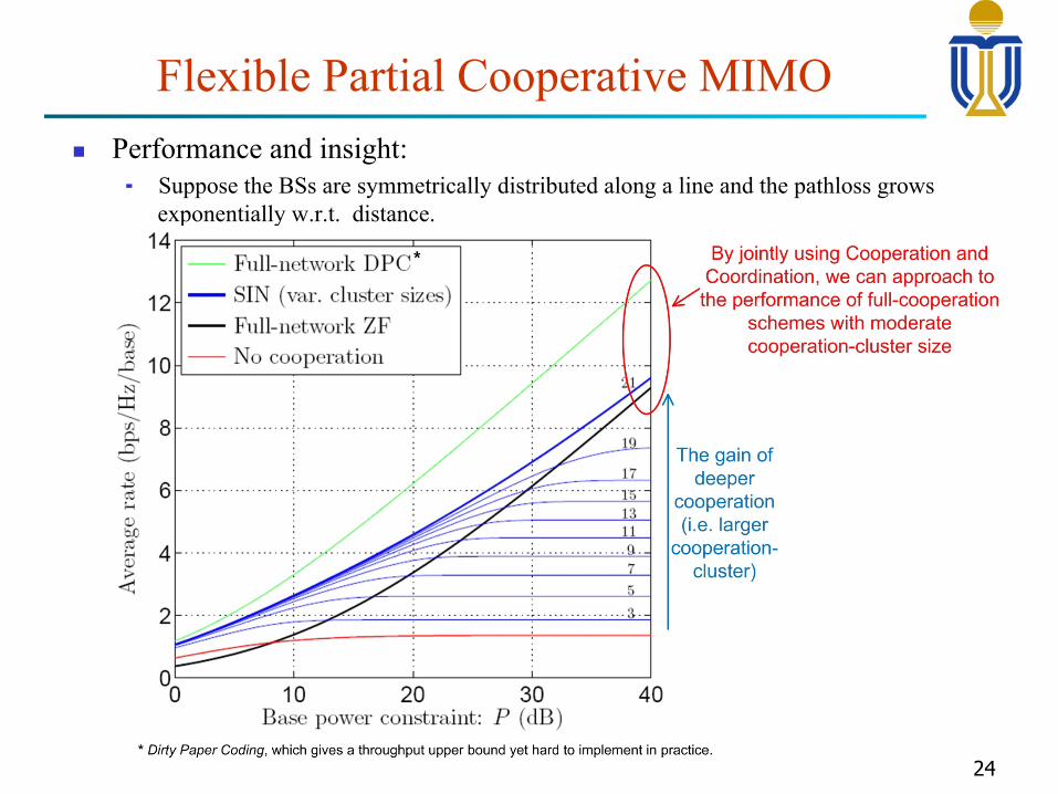
Flexible Partial Cooperative MIMO n Performance and insight:
¬ Suppose the BSs are symmetrically distributed along a line and the pathloss grows exponentially w.r.t. distance.
24
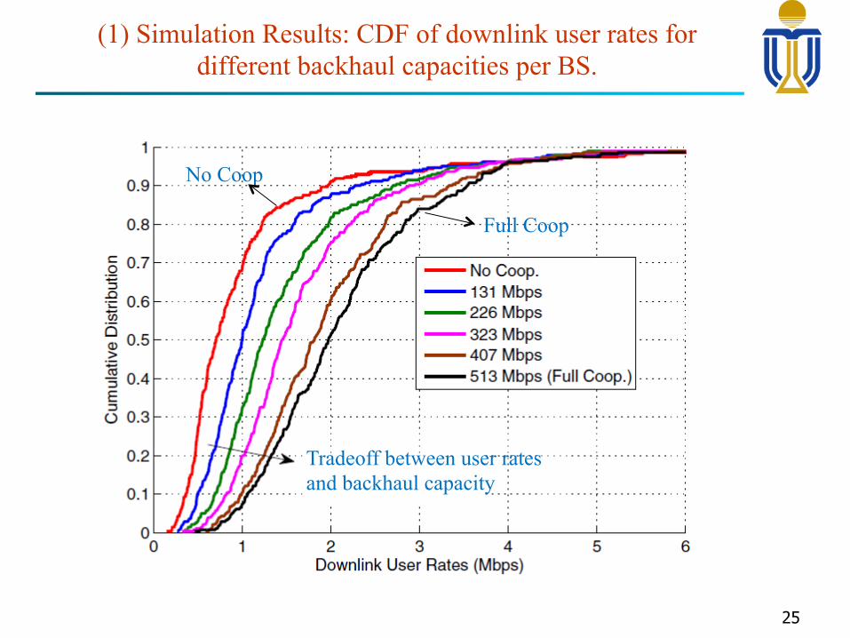
(1) Simulation Results: CDF of downlink user rates for different backhaul capacities per BS.
25
No Coop
Full Coop
Tradeoff between user rates and backhaul capacity
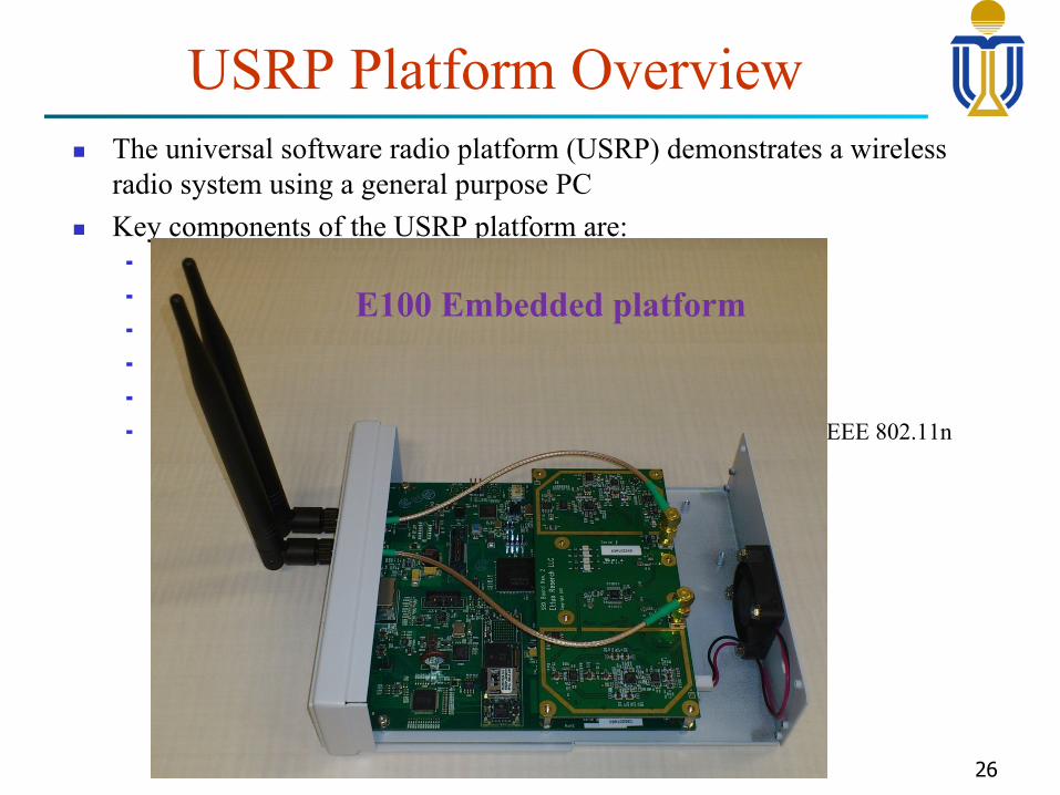
USRP Platform Overview n The universal software radio platform (USRP) demonstrates a wireless
radio system using a general purpose PC n Key components of the USRP platform are:
¬ General purpose PC ¬ Universal software radio platform (USRP) board ¬ Transceiver board ¬ Indoor antennas ¬ GNU Radio (software development toolkit) ¬ Hydra (wireless testbed which supports most features specified in the IEEE 802.11n
standard)
26
Host PC
TransceiverBoard
TransceiverBoard
USB
Tx
Rx
Tx
Rx
USRP Board
Connection Diagram of the USRP Board
E100 Embedded platform
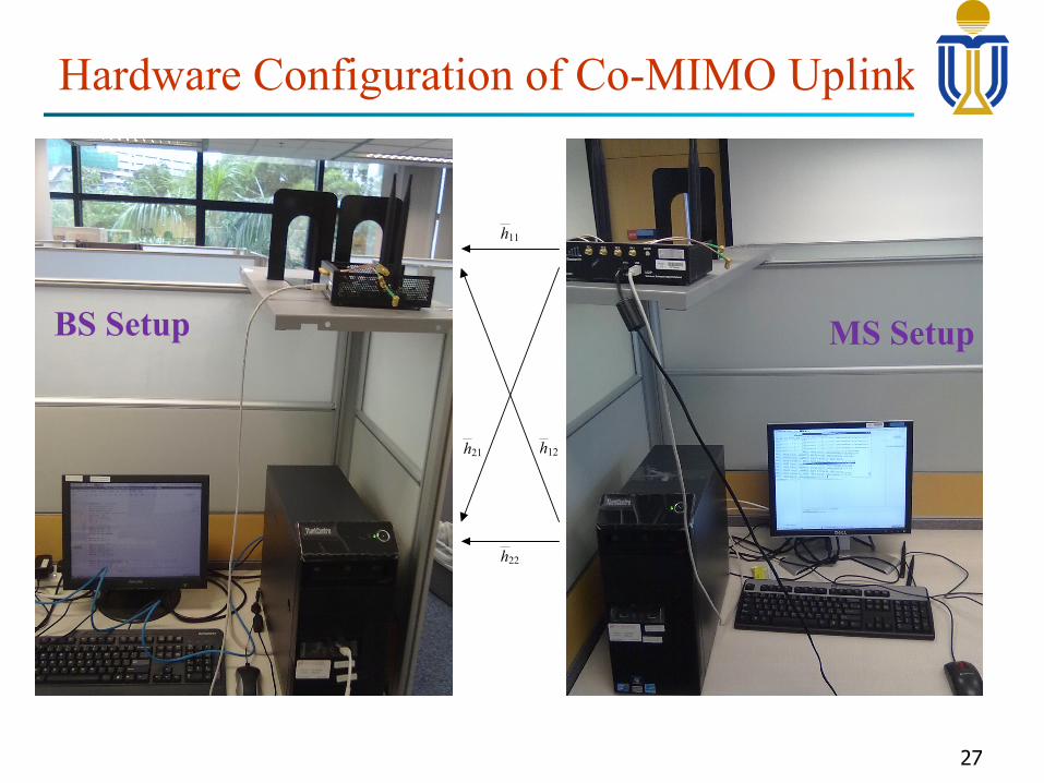
Hardware Configuration of Co-MIMO Uplink
27
h12
XCVR2450Board
XCVR2450Board
LANcable
Tx/Rx
Tx/RxUS
RP
Boa
rdHost PCUSB
MS #1
US
RP
Boa
rd
Host PCXCVR2450Board
USBTx/Rx
MS #2
US
RP
Boa
rd
XCVR2450Board
XCVR2450Board
Tx/Rx
Tx/RxUS
RP
Boa
rd
USB
BS #1
BS #2
XCVR2450Board
Tx/RxHost PC
Host PC
USBh11
h22
y1
y2
x1
x2
h21
BS Setup MS Setup
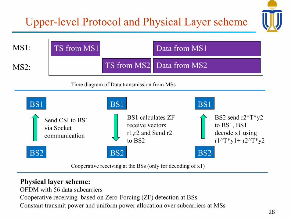
Upper-level Protocol and Physical Layer scheme
28
TS from MS1
TS from MS2
Data from MS1
Data from MS2
MS1:
MS2:
BS1
BS2
Send CSI to BS1 via Socket communication
BS1
BS2
BS1 calculates ZF receive vectors r1,r2 and Send r2 to BS2
BS1
BS2
BS2 send r2^T*y2 to BS1, BS1 decode x1 using r1^T*y1+ r2^T*y2
Time diagram of Data transmission from MSs
Cooperative receiving at the BSs (only for decoding of x1)
Physical layer scheme: OFDM with 56 data subcarriers Cooperative receiving based on Zero-Forcing (ZF) detection at BSs Constant transmit power and uniform power allocation over subcarriers at MSs
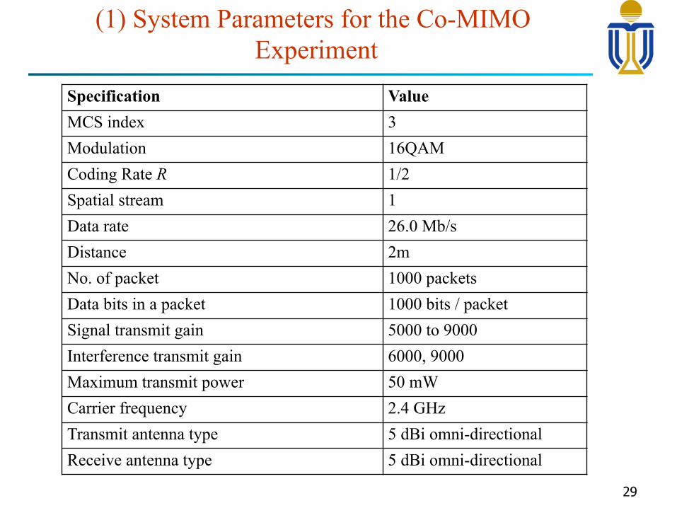
(1) System Parameters for the Co-MIMO Experiment
29
Specification Value MCS index 3 Modulation 16QAM Coding Rate R 1/2 Spatial stream 1 Data rate 26.0 Mb/s Distance 2m No. of packet 1000 packets Data bits in a packet 1000 bits / packet Signal transmit gain 5000 to 9000 Interference transmit gain 6000, 9000 Maximum transmit power 50 mW Carrier frequency 2.4 GHz Transmit antenna type 5 dBi omni-directional Receive antenna type 5 dBi omni-directional
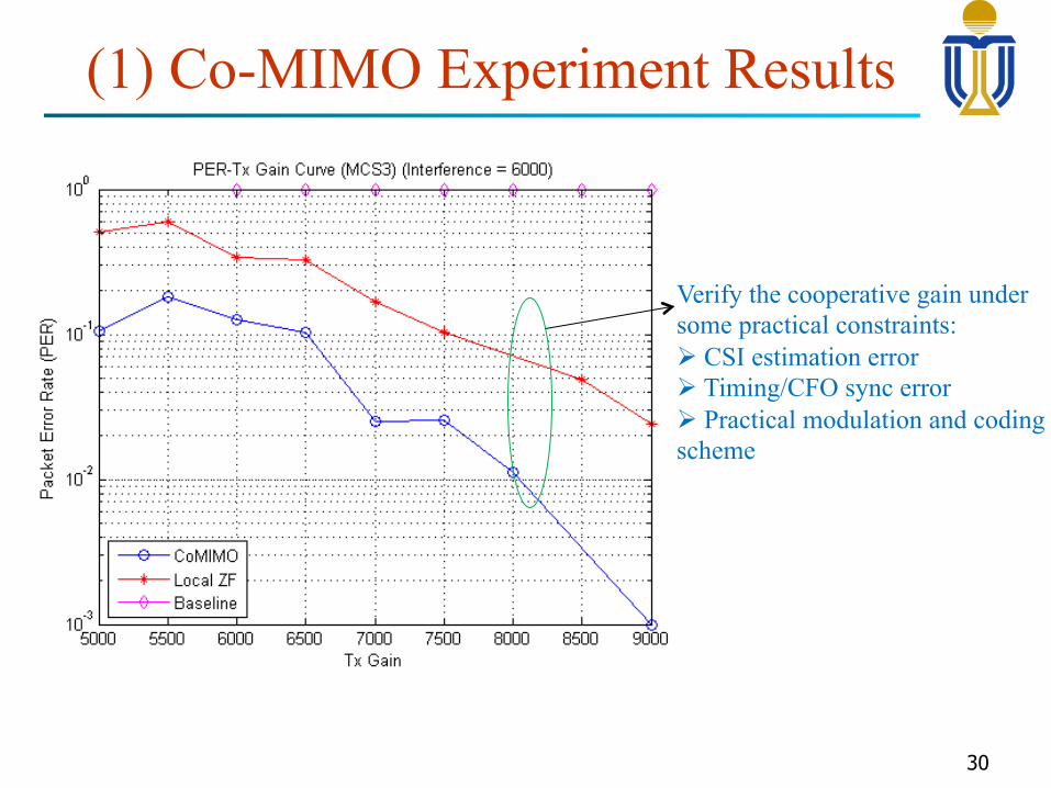
(1) Co-MIMO Experiment Results
30
Verify the cooperative gain under some practical constraints: Ø CSI estimation error Ø Timing/CFO sync error Ø Practical modulation and coding scheme
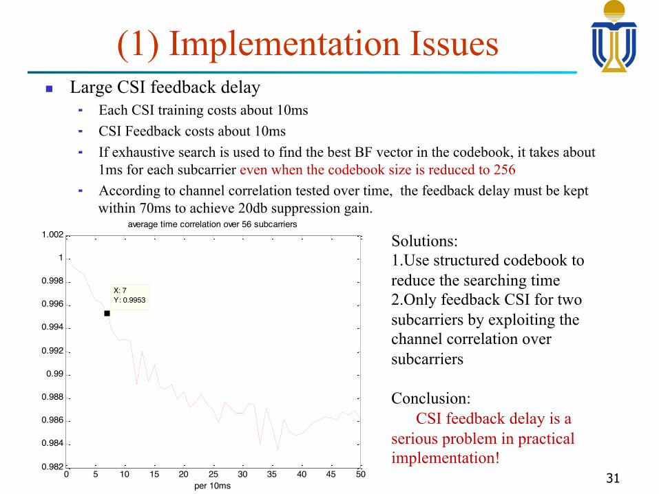
(1) Implementation Issues n Large CSI feedback delay
¬ Each CSI training costs about 10ms ¬ CSI Feedback costs about 10ms ¬ If exhaustive search is used to find the best BF vector in the codebook, it takes about
1ms for each subcarrier even when the codebook size is reduced to 256 ¬ According to channel correlation tested over time, the feedback delay must be kept
within 70ms to achieve 20db suppression gain.
31 0 5 10 15 20 25 30 35 40 45 500.982
0.984
0.986
0.988
0.99
0.992
0.994
0.996
0.998
1
1.002
X: 7Y: 0.9953
average time correlation over 56 subcarriers
per 10ms
Solutions: 1. Use structured codebook to reduce the searching time 2. Only feedback CSI for two subcarriers by exploiting the channel correlation over subcarriers
Conclusion: CSI feedback delay is a serious problem in practical implementation!
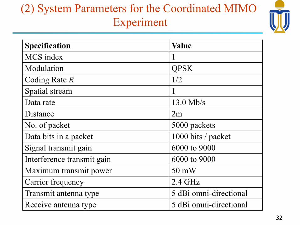
(2) System Parameters for the Coordinated MIMO Experiment
32
Specification Value MCS index 1 Modulation QPSK
Coding Rate R 1/2 Spatial stream 1 Data rate 13.0 Mb/s Distance 2m
No. of packet 5000 packets Data bits in a packet 1000 bits / packet Signal transmit gain 6000 to 9000 Interference transmit gain 6000 to 9000 Maximum transmit power 50 mW
Carrier frequency 2.4 GHz Transmit antenna type 5 dBi omni-directional Receive antenna type 5 dBi omni-directional
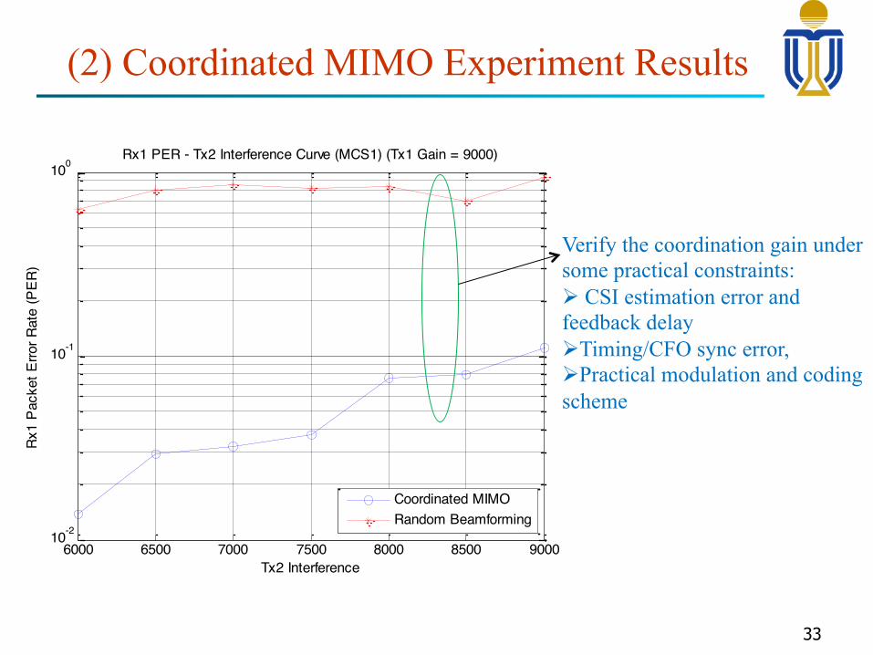
(2) Coordinated MIMO Experiment Results
33
6000 6500 7000 7500 8000 8500 900010-2
10-1
100
Tx2 Interference
Rx1
Pack
et E
rror R
ate
(PER
)
Rx1 PER - Tx2 Interference Curve (MCS1) (Tx1 Gain = 9000)
Coordinated MIMORandom Beamforming
Verify the coordination gain under some practical constraints: Ø CSI estimation error and feedback delay Ø Timing/CFO sync error, Ø Practical modulation and coding scheme
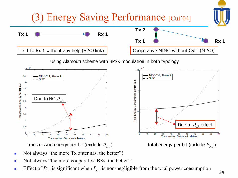
(3) Energy Saving Performance [Cui’04]
n Not always “the more Tx antennas, the better”! n Not always “the more cooperative BSs, the better”! n Effect of Pcct is significant when Pcct is non-negligible from the total power consumption
34
Tx 1
Tx 2 Tx 1 Rx 1
Rx 1
Tx 1 to Rx 1 without any help (SISO link) Cooperative MIMO without CSIT (MISO)
Transmission energy per bit (exclude Pcct ) Total energy per bit (include Pcct )
Using Alamouti scheme with BPSK modulation in both typology
Due to Pcct effect
Due to NO Pcct
Conclusion
35
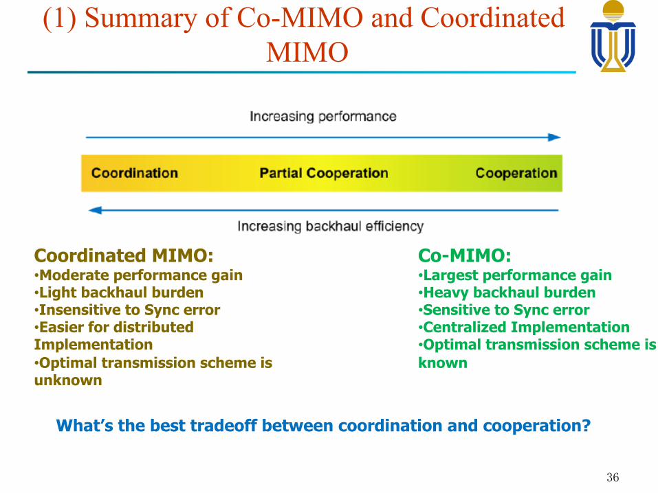
(1) Summary of Co-MIMO and Coordinated MIMO
36
Coordinated MIMO: • Moderate performance gain • Light backhaul burden • Insensitive to Sync error • Easier for distributed Implementation • Optimal transmission scheme is unknown
Co-MIMO: • Largest performance gain • Heavy backhaul burden • Sensitive to Sync error • Centralized Implementation • Optimal transmission scheme is known
What’s the best tradeoff between coordination and cooperation?
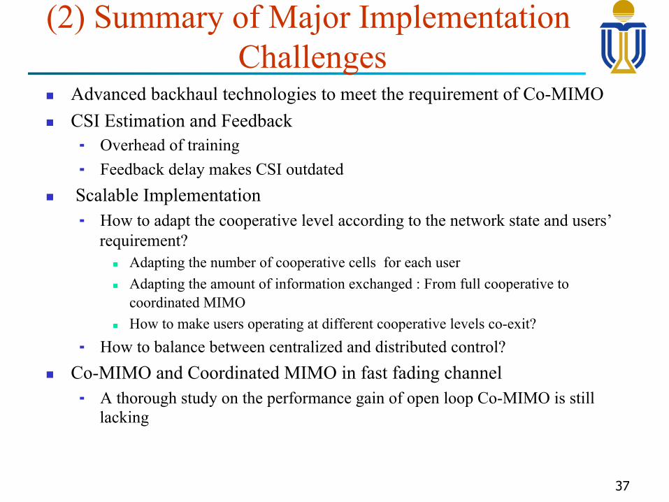
(2) Summary of Major Implementation Challenges
n Advanced backhaul technologies to meet the requirement of Co-MIMO n CSI Estimation and Feedback
¬ Overhead of training ¬ Feedback delay makes CSI outdated
n Scalable Implementation ¬ How to adapt the cooperative level according to the network state and users’
requirement? n Adapting the number of cooperative cells for each user n Adapting the amount of information exchanged : From full cooperative to
coordinated MIMO n How to make users operating at different cooperative levels co-exit?
¬ How to balance between centralized and distributed control? n Co-MIMO and Coordinated MIMO in fast fading channel
¬ A thorough study on the performance gain of open loop Co-MIMO is still lacking
37

n Energy per bit metric n Circuit power consumption Pcct is constant as long as
transmission rate ≠ 0 ¬ Further complicates the Co-MIMO and Coordinated MIMO
design n The choice of # of Tx antennas is a combinatorial problem
¬ Not always use all the Tx antennas ¬ Not always involve in more cooperative BSs ¬ Effect of Pcct is significant when Pcct is non-negligible from the
total power consumption
(3) Summary of the Green Aspects of Co-MIMO and Coordinated MIMO
38
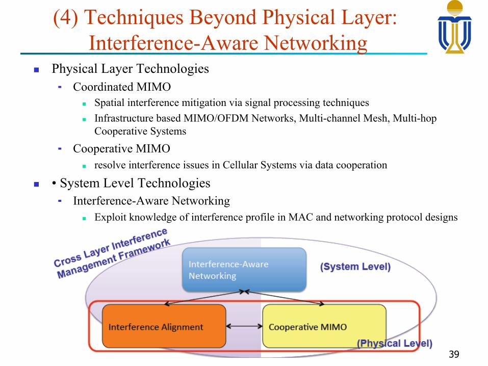
(4) Techniques Beyond Physical Layer: Interference-Aware Networking
n Physical Layer Technologies ¬ Coordinated MIMO
n Spatial interference mitigation via signal processing techniques n Infrastructure based MIMO/OFDM Networks, Multi-channel Mesh, Multi-hop
Cooperative Systems
¬ Cooperative MIMO n resolve interference issues in Cellular Systems via data cooperation
n • System Level Technologies ¬ Interference-Aware Networking
n Exploit knowledge of interference profile in MAC and networking protocol designs
39