interference mitigated zigbee based advanced metering …€¦ · for the large scale modeling and...
TRANSCRIPT
1551-3203 (c) 2015 IEEE. Personal use is permitted, but republication/redistribution requires IEEE permission. See http://www.ieee.org/publications_standards/publications/rights/index.html for more information.
This article has been accepted for publication in a future issue of this journal, but has not been fully edited. Content may change prior to final publication. Citation information: DOI 10.1109/TII.2016.2527618, IEEETransactions on Industrial Informatics
1
Abstract—An interference-mitigated ZigBee based Advanced
Metering Infrastructure solution, namely IMM2ZM, has been
developed for high traffics smart metering. The IMM2ZM
incorporates multi-radios multi-channels network architecture
and features an interference mitigation design by using
multi-objective optimization. To evaluate the performance of
the network due to interference, the channel swapping time (Tcs)
has been investigated. Analysis shows that when the sensitivity
(PRX) is less than -12dBm, Tcs increases tremendously.
Evaluation shows that there are significant improvement in the
performance of the application layer transmission rate (σ) and
the average delay (D). The improvement figures are: σ > ~300%
and D >70% in a 10-floor building; σ > ~280% and D >65% in a
20-floor building; and σ > ~270% and D >56% in a 30-floor
building. Further analysis reveals that IMM2ZM results in
typically less than 0.43 sec delay for a 30-floor building under
interference. This performance fulfills the latency requirement
of less than 0.5 sec for SMs [31] in the USA. The IMM2ZM
provides a high traffics interference-mitigated ZigBee
Advanced Metering Infrastructure solution.
Index Terms—Smart Grid, High traffics AMI, ZigBee,
Interference mitigation, Multi-objective optimization,
Multi-radios, Multi-channels.
I. INTRODUCTION
HE development of smart Grid is imperative and is
identified by the USA Department of Energy as the key
development revitalizing USA’s electric infrastructure.
Smart metering (SM) supports distributed technologies and
consumer participation, and extracts energy data using
two-way communication [1]-[2]. Pertinent to the nature of
SM, the wireless sensor network (WSN) is a vital component
in smart grid communication [3]-[4]. The ZigBee wireless
protocol is commonly used in WSN and adopted as one of the
standards in SM [5].
In most smart cities, there are many tall buildings. These
high rises normally present a hostile environment for
Manuscript received November 18, 2014; revised March 22, 2015 and 18
October 2015; Accepted January 20, 2016. Copyright © 2009 IEEE. Personal use of this material is permitted.
However, permission to use this material for any other purposes must be
obtained from the IEEE by sending a request to [email protected] H. R. Chi, K. F. Tsang, K. T. Chui and H. S. H. Chung are with the
Department of Electronic Engineering, City University of Hong Kong,
Kowloon, Hong Kong (e-mail: [email protected], [email protected], [email protected],
B. W. K. Ling is with Guangdong University of Technology, Guangzhou, Guangdong, China (e-mail: [email protected]).
L. L. Lai is with State Grid Energy Research Institute, Beijing, China
(e-mail: [email protected]).
wireless signals. ZigBee is dedicated to smart energy
applications and has been extensively adopted in smart
energy applications. By taking advantage of ZigBee Smart
Energy open standard and its mesh capability for scalability,
researchers find it advantageous and efficient to adopt
ZigBee in SM applications. It was pointed out that, in urban
area, a huge aggregation of data created the need to
investigate building area networks (BANs) [6, 7]. However,
high rises are typically comprised of hard reinforced concrete,
rendering signal propagations are difficult in general. A
modern smart city is normally full of civilians with enriched
lives that normally demands communication using WiFi or
Bluetooth for wireless delivery in the same frequency band.
Thus, the application of ZigBee to Advanced Metering
Infrastructure (AMI) in high traffic areas needs to be handled
with special consideration to mitigate the potentially hostile
interferences.
A former design of HTAMI did not consider interference
[8]. However, the high attenuation and dispersive
characteristics of concrete construction in ZigBee BAN
(ZBAN) demands AMI features that mitigate interference. In
this investigation, an interference model will be investigated.
A new design and implementation of interference-mitigated
ZBAN for HTAMI will be proposed and developed.
In the design, there are multiple parameters that are
indicative for consideration, for instance, high power and
high throughput for fast data transmission and low latency
for good QoS etc. However, the magnitude of these factors
may bear contradictive meanings, for example, the high
power transmission that causes the feeling of potential health
hazard versus the well accepted low power, the high
throughput demanded by users versus the low throughput
generally achieved in a hostile environment, the low latency
commonly requested versus the high latency normally occurs
in noisy communications. A salient solution can be achieved
by optimizing these key parameters. In this investigation,
prior experimental work was conducted to acquire the
background data pertinent to the characteristics of the
ZBAN.
In the experiment, measurement data of a five-storey
building was conducted to collect prime data to pave the way
for the large scale modeling and analysis of the complicated
high traffics scenario. The interference mitigation model for
ZigBee transmission will also be derived. It will be explained
that the Non-Dominated Genetic Algorithm-II (NSGA-II) is
customized to obtain the pareto fronts from which the
appropriate design will be developed. The OPNET is then
employed for a large scale evaluation and analysis. The
measured data are used for optimization and model
generation in the OPNET environment. Measurement results
show that the developed IMM2ZM satisfies the demand
Interference-Mitigated ZigBee Based Advanced
Metering Infrastructure
Hao Ran Chi, Student Member, IEEE, Kim Fung Tsang, Senior Member, IEEE, Kwok Tai Chui, Student
Member, IEEE, Henry Shu-Hung Chung, Fellow, IEEE, Bingo Wing Kuen Ling, Senior Member, IEEE,
Loi Lei Lai, Fellow, IEEE
T
1551-3203 (c) 2015 IEEE. Personal use is permitted, but republication/redistribution requires IEEE permission. See http://www.ieee.org/publications_standards/publications/rights/index.html for more information.
This article has been accepted for publication in a future issue of this journal, but has not been fully edited. Content may change prior to final publication. Citation information: DOI 10.1109/TII.2016.2527618, IEEETransactions on Industrial Informatics
2
response requirement of the US standards amongst the
hostile environments of HTAMI.
The contribution of this paper is as follows:
1. A prior measurement was performed to obtain the prime
data for the formulation of objective functions of the optimal
solution at large scale;
2. An interference mitigation model has been derived;
3. A customization to NSGA-II [26] optimization has been
developed;
4. OPNET evaluation has been implemented for large
scale analysis;
5. A channel swapping interference-mitigated multi-radio
multi-channel ZigBee metering (IMM2ZM) system has been
implemented for IMM2ZM system for high traffics AMI.
This paper is organized as follows: The introduction of the
related work is given in Section II. The design of IMM2ZM
is presented in Section III and the system IMM2ZM model in
Section IV. The multi-objective optimization for the
IMM2ZM using NSGA-II is described in section V. The
analysis and evaluation of the IMM2ZM are shown in
Section VI. Finally, a conclusion is given in section VII.
II. MIZBAN AND RELATED WORK
The demand for HTAMI in modernized cities has been
significantly increasing. Wireless data delivery basically
meets the “versatility” need of HTAMI. By virtue of the open
standard nature and mesh capability, ZigBee is the populated
candidate adopted by the industry [8]. It is evidenced that
ZigBee has been applied to SM [1].
Derived from practical needs, a generic design for HTAMI,
namely multi-interface ZigBee building area network
(MIZBAN), was developed by partitioning the network into
two parts, namely the Backbone Network and the Floor
Network and multiple interfaces were developed [8]. In the
MIZBAN, interference was not particularly treated. It is well
evidenced that WiFi, Bluetooth and ZigBee operate in the
same frequency band [12]. In addition, mobile signals such
as 3G, LTE also operate in the vicinity which may cause
adjacent channel or cross channel interference. In order to
provide a good quality of service, interference mitigation for
HTAMI must be developed.
Limited former work was devoted to interference in
ZigBee. For instance, ZigBee deployment guidelines which
include the safe distance and the safe offset frequency for
smart grid applications were developed in an attempt to
mitigate the potential WiFi interference [13]. However, the
WiFi interference in high rises environment is much more
complex since the apartments are close to one another and
WiFi signals scatter around the environment. Therefore,
deployment guidelines alone as captioned in [13] are not
sufficient. In general, an optimal solution to mitigate
interference is difficult to be obtained.
A generic cross layer optimization for caching was also
discussed for multi-interface multi-radio (M2) WSN [18].
However, only a few discussions focused on IEEE 802.15.4.
A comparative study of WiFi and IEEE 802.15.4 for M2 was
provided in [19]. A M2 MAC layer design for IEEE 802.15.4
was also presented in [20] but the discussion was only based
on the MAC layer of ZigBee and the network layer and
application layer were not considered. It is seen that there is
still much room for further development. In this paper, based
on IEEE 802.15.4, a cross layer design into the network layer
and application layer will be investigated. Particular interest
will be devoted to the interference mitigation design for
HTAMI. In this investigation, an interference mitigation
solution, namely IMM2ZM, has been developed and analysis
will be discussed.
III. DESIGN OF IMM2ZM
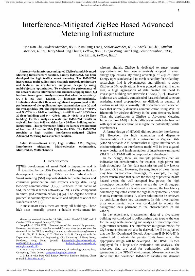
A. IMM2ZM Basic Structure
Akin to MIZBAN [8], the proposed architecture of
IMM2ZM is also divided into the backbone network and the
floor network (Fig. 1). The backbone network refers to a
multi-radio ZigBee mesh network that is formed by a
Reading Centralizer (RC) with multiple Reading Meter
Terminals (RMT) deployed into the meter room on each
floor (this is a common configuration in Asia).
Multiple-radio was devised in the IMM2ZM backbone
network to share the traffic loadings to facilitate fast data
delivery. The backbone network interacts with the Meter
Data Management System (MDMS) to provide the utility
services such as meter management (MM), Meter Record
Oder (MRO) and Load Profile (LP). Apart from the
backbone network, RMTs are connected wirelessly with
In-Home Displays (IHDs) to form another ZigBee
single-radio network, namely floor network, to facilitate end
users to obtain real time meter readings. The functions of
each component are summarized as follows:
Subnet
1Subnet
n
Subnet
1Subnet
n
Subnet
1Subnet
n
M/F
2/F
1/F
IHD RMT
RCExisting
Meter
Data Bus
ZigBee Single Radio
(IMM2ZM Floor
Network)
ZigBee Multi-Radio
(IMM2ZM Backbone)
Fig. 1 Architecture for IMM2ZM.
The IMM2ZM incorporates multiple channels to achieve
good latency [8]. Also, channel swapping is incorporated to
facilitate interference mitigation.
B. Multi-Layer Design of IMM2ZM Backbone
Communication
The network layer and the application layer of the M2
backbone network have been designed to interoperate with
the current ZigBee standard. ZigBee implements two layers
on top of the 802.15.4 MAC layer, namely the Network layer
and the Application security layer. The IMM2ZM design
consists of the followings: network initialization, swappable
1551-3203 (c) 2015 IEEE. Personal use is permitted, but republication/redistribution requires IEEE permission. See http://www.ieee.org/publications_standards/publications/rights/index.html for more information.
This article has been accepted for publication in a future issue of this journal, but has not been fully edited. Content may change prior to final publication. Citation information: DOI 10.1109/TII.2016.2527618, IEEETransactions on Industrial Informatics
3
channel registration, address distribution, routing control,
application security. The process tasks and protocol
architecture will be described.
The Network layer is situated above the IEEE 802.15.4
MAC. One of the missions of the network layer is to
empower IEEE 802.15.4 devices to deal with a variable
network size application. There are three main tasks for the
network layer: (1) network initialization, (2) address
distribution and (3) routing control. The network
initialization includes the management of network formation
and the devices. Address distribution aims at arranging a
unique network address to each device in a ZigBee network.
Routing control is a mechanism to maintain the end-to-end
reliability and transfer packets through the network.
1) Network Initialization
Basically, this design is mainly applied to multi-radio
devices, e.g. the RC and RMTs. Generally, RMT is the
backbone infrastructure which aims to relay the information
across different floors to the RC.
When an interference source is detected at an occupied
channel, the channel-swapping process will be activated to
ensure the reliability of the IMM2ZM system. For example,
if the ZigBee radio 1 of RMT A at channel B is jammed by
strong interference and thus experience continuous
transmission failure, the ZigBee radio 1 of RMT A will issue
the Channel_Jam_Report to the RC with the jammed channel
ID. Then the RC will broadcast the Channel_Scan_Req
(channel ID) to all RMTs through channel A. After the
channel scanning, the RC will send Channel_Result_Req to
each RMT to collect the scan results and then select a new
channel and broadcast Channel_Update_Req to all RMTs.
The selection of the new channel is mainly based on the
principle that channels with larger frequency separation
intercepts less co-channel interference. Normally there are 16
frequency channels available in IEEE 802.15.4, namely
channel 1 to channel 16.
Initially, channel 1 will be assigned as the operating
channel. If a traffic jam is detected, the channel swapping
will be incurred based on (1).
2
1&,2|
,12|
1
,19
,17
old
old
old
old
old
new
CH
kZkkxxCH
ZkkxxCH
CH
CH
CH (1)
where CHnew refers to the channel to be selected, CHold is the
previous channel with jam before channel swapping.
The channel jamming issue will be detected on the new
channel until no Channel_Jam_report is received.
1) Address Distribution
When a device joins the network, it is given a 16-bit short
address (network address). Such address is a unique address
in the ZigBee network. Two distributed addressing schemes
are available in the ZigBee Network – the Tree Address
Assignment Scheme and the Stochastic Address Assignment
Scheme.
2) Routing Control
Basically, ZigBee supports two routing mechanisms:
hierarchical (also known as tree) and table driven (also
known as mesh) routing. In particular, Mesh Network
Routing (Table-driven routing) is basically similar to the Ad
hoc On-Demand Distance Vector (AODV) routing protocol
[22] for general multi-hop ad hoc networks. For the design of
IMM2ZM, the address distribution and routing mechanism
should be considered together since these two schemes affect
each other.
IV. THE IMM2ZM MODEL
In this section, a system model of IMM2ZM is presented.
The purpose is to aid a system designer to estimate the
performance of IMM2ZM. Let’s consider an IMM2ZM with
k channels in an n-floor building experiencing the
interference from x WiFi devices, y ZigBee devices, z
Bluetooth devices and m other wireless devices such as 3G
and LTE devices from both adjacent channel of IMM2ZM
and non-IMM2ZM network. The total interference power,
Pin(x,y,z,m), receipted by a single IMM2ZM ZigBee receiver
is calculated as [22]:
m
i
i
othersRx
z
i
i
BTRx
y
i
i
ZBRx
x
i
i
WiFiRxNin PPPPPmzyxP1
,
1
,
1
,
1
,0),,,(
(2)
where PN0, PRx,WiFi, PRx,ZB, PRx,BT, PRx,others are the noise power,
WiFi interferer power, ZigBee interferer power, Bluetooth
interferer power and interferer power from other sources
respectively.
The Bit Error Rate (BER) of a single IMM2ZM ZigBee
receiver interfered by x WiFi devices, y ZigBee devices, z
Bluetooth devices and m other wireless devices including
from both adjacent channel of IMM2ZM and non-IMM2ZM
network,mzyxB ,,,
, is then evaluated as:
)),,,(
log102(,
10,,,
fading
in
ZBRx
mzyx PPGmzyxP
PQB
(3)
Where [23]
duu
xQx
)2
exp(2
1)(
2
(4)
Pfading is the fading loss, and PG is the process gain, and
0.85 [25].
Special consideration is drawn to the derivation of BER of
ZigBee packets amongst the interference of all potential
sources. The extreme cases that packets are transmitted
successfully (Psucc) as well as the case that all IMM2ZM
devices are busy (Pbs) are considered. Assuming the packet
length is L bits and h IMM2ZM devices are competing.
Denote Psucc be the probability of successfully transmitted a
correct packet (with every bit in the packet correctly
transmitted) and Pbs be the probability that all IMM2ZM
devices are busy when a packet is sent to a specific ZigBee
transceiver of IMM2ZM devices. Psucc and Pbs are evaluated
as:
Lmzyxsucc BP ,,,1 (5)
11
h
bsP (6)
ZigBee performs Clear Channel Assessment (CCA) four
times before reporting failure, thus the transmission
probability, τ, is evaluated from the channel busy probability,
α. In this work, four channels are used, hence α is defined as
follows: 41 (7)
For performance evaluation purpose, the packet error rate,
Perr, is evaluated by incorporating Pbs into consideration.
Hence Perr is now defined as:
bs
succerr
P
PP 1 (8)
In IMM2ZM, the channel busy probability, α, is then
1551-3203 (c) 2015 IEEE. Personal use is permitted, but republication/redistribution requires IEEE permission. See http://www.ieee.org/publications_standards/publications/rights/index.html for more information.
This article has been accepted for publication in a future issue of this journal, but has not been fully edited. Content may change prior to final publication. Citation information: DOI 10.1109/TII.2016.2527618, IEEETransactions on Industrial Informatics
4
derived as:
)1)(1)(1)(1(1 2222
others
ZMIMM
ZB
ZMIMM
WiFi
ZMIMM
BT
ZMIMM
(9)
where BT
ZMIMM 2 , WiFi
ZMIMM 2 , ZB
ZMIMM 2 denote the CCA busy
probability of a given IMM2ZM devices due to Bluetooth
devices, WiFi devices, ZigBee respectively. others
ZMIMM 2 refers
to other interferers such as 3G and LTE devices.
The tagged IMM2ZM device is modeled as M/G/1
queuing system. It is assumed that: (i) h IMM2ZM devices
are competing; (ii) each IMM2ZM device generates packet
conforming to Poisson process of packet generation rate λM;
(iii) Data packet size is constant with bM seconds. By
incorporating TBO, Tturn, TSW, TACK, and following [24], ZB
ZMIMM 2 is expressed as:
1-
][][1
)2]([)][1)(1(
M
MBO
4
22
q
SWACKturn
ZB
ZMIMMZB
ZMIMM
DEE
TTTbTEh
(10)
where TBO, Tturn, TSW and TACK are the time for backoff, turn
around, switching and transmit acknowledgement
respectively. In (10), channel swapping is specifically
addressed to ensure the busy probability of IMM2ZM
devices has taken consideration of interference. E[Г] is the
average number of packets served by the tagged IMM2ZM
device in a busy period and is defined as E[Г] = 1/(1-ρ) where
traffic intensity ρ = λM(E[Dq]+bM+2Tturn+TACK). E[Dq]
denotes the queueing delay which refers to the duration that
the packet in the system queues before transmission or
discarded. Substituting E[Г] to (10), ZB
ZMIMM 2 is
manipulated as:
1-)2(-1
)2)(][1)(1(
MM
MBO
4
2M
2
ACKturn
SWACKturn
ZB
ZMIMMZB
ZMIMMTTb
TTTbTh
(11)
With the newly defined Perr in (8), the single hop
transmission channel throughput, S, for an IMM2ZM device
with single radio is expressed as:
ffccssi
s
PTPTPTP
P
p8LS (12)
h
iP )1( (13)
)1()1( 1
err
h
s PhP (14)
err
h
f PhP 1)1( (15)
fsic PPPP 1 (16)
where Lp is the payload of packet in bytes; Pi is the
probability that the time slot is idle; Ps is the probability of
successful transmission without channel error and collision
in a time slot; Pf is the probability of channel error occurs in a
time slot; Pc is the probability that collision occurs in a time
slot; δ is the duration of idle time slot; Ts is the average
channel busy time due to successful transmission; Tc is the
average channel busy time due to collision; and Tf is the
transmission failure time due to channel error. Ts, Tc and Tf
follow the meanings from [21] and the relationship between
Ts, Tc and Tf are given by:
IFSACKMs TTbT 2 (17)
IFSACKMfc TTbTT / (18)
The overall transmission of IMM2ZM with k radios is now
investigated. Consider a high rise building with n floors and
each floor has Na apartments. Assuming a smart meter stores
Nr records for data recovery and the record length is Nb bits.
The sleep-to-join time for each node is Ts2j.Therefore the
meter reading collection duration for a specific floor
demanding c hops from transceivers, T(c), is newly derived
according to the detail construction of the building as:
k
cT
S
NNNcT js
bra
2)( (19)
Thus, T(c) gives an account of multiple hops and
multi-channels. The general knowledge of the average delay,
D, is the amount of time required to transmit all of the
packet's bits successfully. D is the primary parameter for
wireless communication network design For SM, a large D
largely impacts the effectiveness of the system [24]. To
facilitate more advanced applications such as real-time
pricing, a low value of D is demanded. In IMM2ZM, D is
also defined as the time of collection of the meter readings of
the entire building.
n
Tk
cT
S
NNN
D
n
i
iCSjs
bria
1
,2
, ])[(
(20)
where Tcs,i is the Channel Swapping Time of the respective
Na,i. Tcs,i will be defined in section V.
In general, the transmission rate, the number of bits
transmitted successfully in a unit time, is an important
performance indicator for wireless communication. In
essence, data overlay the entire network on the application
layer from which they are processed. With high traffics in
high-rises, the quantity of data transmitted in a time slot is
bulky. Thus the transmission rate on the application layer
affects significantly the network performance.
Therefore, the application layer transmission rate, σ, a
pertinent descriptor of IMM2ZM, is defined as:
D
NNN bra (21)
From the captioned analysis, D and σ are pertinent
descriptors providing a holistic view of the latency
performance that take account of the total number of hops
and the interference mitigation. Thus, D and σ are indicative
figures to quantify the performance of the IMM2ZM in BAN.
V. MULTI-OBJECTIVE OPTIMIZATION BASED ON NSGA-II
To synthesize the performance of IMM2ZM, the system
requirement will be formulated and an optimization is needed.
As such, a method that fulfills all the objective requirements
is sought for. It is well known that the Genetic algorithm (GA)
is genetically powerful and is a searching mechanism which
imitates the natural procedure of evolution. In most practical
engineering problems including wireless network design,
global optimum does not exist. Therefore the problem cannot
be formulated into single objective optimization problem.
Also, most of the problems in engineering demand the
consideration of multiple conflicting objectives in order to
give a comprehensive and excellent performance; Compared
with single objective optimization, multi-objective
optimization has super advantages as: The diversity of
multi-objective optimization is much wider than single
objective optimization [9]. As a result, the multi-objective
problems render the launch of Multi-Objective Evolutionary
Algorithms (MOEAs). The MOEA is a kind of GA that
1551-3203 (c) 2015 IEEE. Personal use is permitted, but republication/redistribution requires IEEE permission. See http://www.ieee.org/publications_standards/publications/rights/index.html for more information.
This article has been accepted for publication in a future issue of this journal, but has not been fully edited. Content may change prior to final publication. Citation information: DOI 10.1109/TII.2016.2527618, IEEETransactions on Industrial Informatics
5
always searches for a set of nondominated optimal solution
which is referred as Pareto-Front (PF) [9].
MOEAs was successfully applied to the optimization of
Wireless Local Area Network (WLAN) [10]. It is well
evidenced that Nondominated sorting genetic algorithm II
(NSGA-II) is proven to outperform other MOEAs in terms of
convergence and diversity functional analysis [11]. It is
envisaged that NSGA-II is powerful and will provide a wider
distribution of the solutions during the search of optimal
solutions. Thus NSGA-II [26] is employed in this paper for
custom design of an optimal IMM2ZM. The developed
model will minimize the influence of potential interference
with optimal throughput and minimal latency.
The following tasks illustrate the main design concept:
A. Initialization
During the initialization, the population size, constraints,
objective functions and number of parameters are determined.
The crowding distance, the average distance of the two
nearest points representing optimal solutions, is calculated to
estimate the density of the optimal solutions.
B. Multi-Objective Searching Process
The main scope in the Multi-Objective Searching Process
aims at generating a new population for further optimization
to reach the optimal solutions. Selection, crossover and
mutation imitate the process of natural evolution [26]. The
objective values of each objective function of the individuals
in the new population are estimated based on the designed
objective functions. The ranking of the individuals in the
same population is based on domination. Recall from [9] that
solution u dominates solution v, if and only if two conditions
are true: (1) all the objectives in u should perform no worse
than v, (2) at least one objective in u should perform better
than v. Solution u does not dominate solution v if either of the
conditions is violated. Solutions that are not dominated by
other solutions in the population have the highest ranking.
The iteration process will be completed when the
maximum generation is reached or the output converges, and
thus the PF is obtained. Every solution in the PF is an optimal
solution and does not dominate each other.
Owing to the simplicity of computation in optimization,
prioritized objective functions are sometimes used and
weighting factors are assigned to the objective functions. In
contrast, multi-objective optimization has a wider diversity
to search for optimal solutions in wider range. An
investigation is made to explore the effectiveness between
these two schemes. The comparison wil be shown in later
context.
C. Network Representation
To start with, the network needs to be modeled. Important
information such as the number of floors, maximum number
of channels etc will firstly be obtained. The NSGA-II
optimization will then be customized and incorporated to
evaluate the optimal solution.
D. Design Constraints
To facilitate the search, it is necessary to assign reasonable
upper and lower limits of the parameters which conform to
the unique design of the network. Reasonable limits may
effectively reduce the quantity of undesirable individuals
during the operation, thus reducing the computing time
significantly.
E. Design of Fitness Values
In general, for multi-objective optimization, the objective
functions are expressed as [26]:
Minimize T
m xfxfxF ))(),...,(()( 1 (22)
Subject to x
where )(xfm is the objective values for each individual in
the whole population, and Ω is the variable range.
A feasibility study was carried out. However, it is
impracticable, if not impossible, to perform a full scale
measurement in high rises. Therefore, prior measurement
was performed for the provision of realistic data to support
the model construction of IMM2ZM. For the same reason
described in [8], the performance of the large scale IMM2ZM
is analyzed using OPNET model and simulation [27].
Interference mitigation model developed in section IV will
be incorporated into the OPNET to achieve a full scale
performance evaluation of IMM2ZM.
There are mainly two parts in the feasibility study. 1) a
small scale IMM2ZM prior measurement using four ZigBee
physical channels; and 2) A large scale simulation of the
IMM2ZM using OPNET model. The feasibility study is
mandatory since it analyzes the performance of developed
IMM2ZM. Besides, the measured data in the prior
measurement also plays an important role in the initialization
of the parameters in objective functions for the optimization.
For example, in (2), PN0, PRx,WiFi, PRx,ZB, PRx,BT and PRx,others
each varies at numerous wireless environment within floors
of buildings. These parameters will be estimated based on the
measured data in the prior measurement to give a more
accurate formulation for ZBAN at large scale. In essence, α
in (9), TBO, Tturn, TSW and TACK in (11) and Ts2j in (19) were
evaluated in the prior measurement in the feasibility study
and thus provided good estimates in the large scale model.
To facilitate testing, an IMM2ZM was set up in a
residential building. In the prior measurement, a five-floor
IMM2ZM using four ZigBee physical channels was
developed and measured. The 5-floor IMM2ZM consists of
five 4-radio RMTs and one 4-radio RC. The experimental
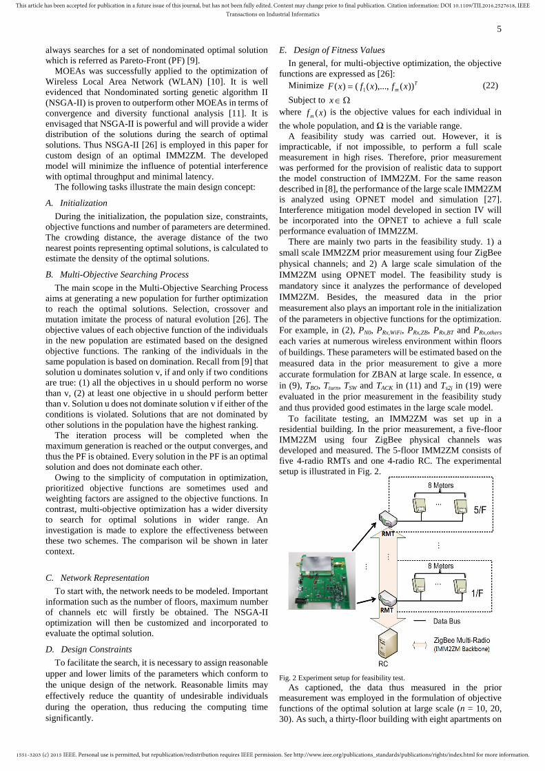
setup is illustrated in Fig. 2.
Fig. 2 Experiment setup for feasibility test.
As captioned, the data thus measured in the prior
measurement was employed in the formulation of objective
functions of the optimal solution at large scale (n = 10, 20,
30). As such, a thirty-floor building with eight apartments on
1551-3203 (c) 2015 IEEE. Personal use is permitted, but republication/redistribution requires IEEE permission. See http://www.ieee.org/publications_standards/publications/rights/index.html for more information.
This article has been accepted for publication in a future issue of this journal, but has not been fully edited. Content may change prior to final publication. Citation information: DOI 10.1109/TII.2016.2527618, IEEETransactions on Industrial Informatics
6
each floor, i.e n = 30 and Na = 8, is considered at large scale.
The RC collected the meters data once every 30 minutes and
the smart meter stored the latest 10 records, i.e. Nr = 10. The
system specifications of IMM2ZM for both the experiment
and simulation are summarized in Table I. TABLE I
SYSTEM SPECIFICATION OF IMM2ZM
Description Experimental data
Simulation data
Number of floor, n (n-floor) 5 30
Number of apartment per floor, Na 8 8 Number of record stored by smart
meter, Nr
10 10
Record length, Nb, (bits) 32 32 AES 128bit enabled Payload length,
Lp, (Bytes)
60 60
Packet length, L, (Bytes) 127 127 Transmission Power PZB (dBm) 19.6 [-20,20]
Receiver Antenna Gain GRX (dBi) 0 0
Transmitter Antenna Gain GTX (dBi) 0 0
In the prior measurement, a testing was carried out in the
meter room on 1st – 5
th floor to identify the potential WiFi,
Bluetooth, ZigBee, LTE, 3G and other interference sources.
The measured data from the prior measurement serves as
important trustworthy parameters for objective function
analysis. Based on the measured data, important parameters
such as the transmitter and receiver gains, the packet
generation rate as well as the transmission power are
optimized (“genes” in the algorithm) for the network and
device design. On the other hand, D, BER and σ are designed
as the objective functions.
The objective functions are designed as: (1) minimize
average D (F1); (2) minimize average BER (F2); (3)
maximize average σ (F3). The three objective functions are
formulated as:
Minimize num
D
F
num
i
1
1 (23)
Minimize num
B
F
num
i
mzyx 1
,,,
2 (24)
Maximize num
F
num
i
1
3
(25)
Subject to
dBiGRX ]2,0[ , dBiGTX ]2,0[ , dBmpZB ]20,20[
where num is the number of replication of the experiment.
Constraints for each objective function:
D ≤ 0.5 sec [28] to fulfill the demand response (DR)
requirement for SM;
BER ≤ -4105 ; and
σ ≥ 20kbps *.
*In the Hong Kong environment, a data rate of ~10-20kbps is
normally adopted, hence σ ~ 20kbps is employed for
evaluation.
The NSGA-II scheme is then customized to optimize the
network. The key parameters are listed in Table II. TABLE II
PARAMETERS SETTINGS OF NSGA-II
Population size
Maximum number of
generations
Crossover type
Crossover rate
Mutation rate
100
200
Uniform
1
0.2
With the inclusion of number of floors (n) and number of
channels (k), the performance of the IMM2ZM is optimized
for n = 5, 10, 20, 30 and k = 1, 2, 3, 4, and simulated values
for each objective are obtained to search for optimal
solutions.
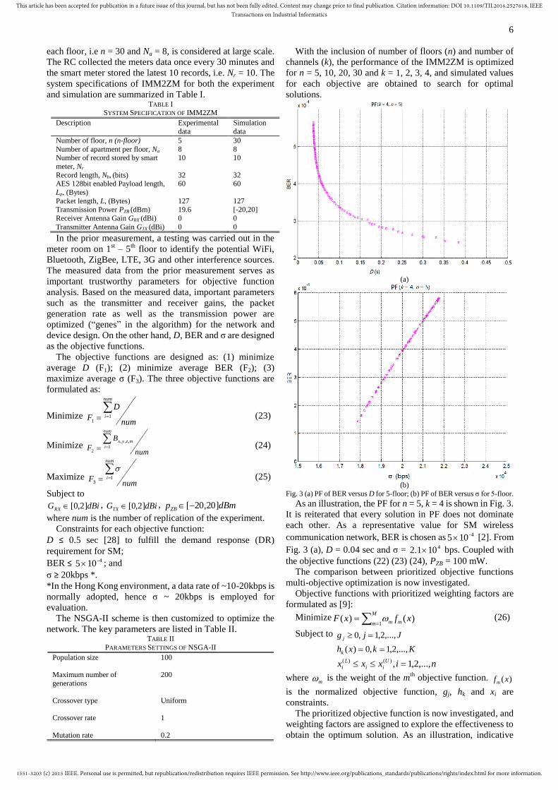
(a)
(b)
Fig. 3 (a) PF of BER versus D for 5-floor; (b) PF of BER versus σ for 5-floor.
As an illustration, the PF for n = 5, k = 4 is shown in Fig. 3.
It is reiterated that every solution in PF does not dominate
each other. As a representative value for SM wireless
communication network, BER is chosen as -4105 [2]. From
Fig. 3 (a), D = 0.04 sec and σ = 4101.2 bps. Coupled with
the objective functions (22) (23) (24), PZB = 100 mW.
The comparison between prioritized objective functions
multi-objective optimization is now investigated.
Objective functions with prioritized weighting factors are
formulated as [9]:
Minimize
M
m mm xfxF1
)()( (26)
Subject to Jjg j ,...,2,1,0
Kkxhk ,...,2,1,0)(
nixxx U
ii
L
i ,...,2,1,)()(
where m is the weight of the m
th objective function. )(xfm
is the normalized objective function, gj, hk and xi are
constraints.
The prioritized objective function is now investigated, and
weighting factors are assigned to explore the effectiveness to
obtain the optimum solution. As an illustration, indicative
1551-3203 (c) 2015 IEEE. Personal use is permitted, but republication/redistribution requires IEEE permission. See http://www.ieee.org/publications_standards/publications/rights/index.html for more information.
This article has been accepted for publication in a future issue of this journal, but has not been fully edited. Content may change prior to final publication. Citation information: DOI 10.1109/TII.2016.2527618, IEEETransactions on Industrial Informatics
7
designs of assigning weighting factors m to the
corresponding objective functions )(xFm are analyzed and
the corresponding results are shown in TABLE III. TABLE III
DESIGN OF WEIGHTING FACTORS FOR THE OBJECTIVES AND THE
CORRESPONDING RESULTS
m )(xFm Description
1 2
3 )(1 xF
(D,s)
)(2 xF
(BER)
)(3 xF
(σ,kbps)
1/3 1/3 1/3 0.07 -4103.4 19.2 D is 42.8% worse than
obtained by
IMM2ZM; σ is 9.5%
less than
obtained by IMM2ZM
0.1 0.1 0.8 0.03 -4106.2 22.8 BER> limitation
0.1 0.8 0.1 0.71 -4101.2 17.5 D>
limitation
0.8 0.1 0.1 0.03 -4106.3 23.2 BER>
limitation
N/A 0.04 -4105.0 21.0 Optimal
result
For 0.121 , 0.83 , the priority of transmission
rate σ is defined to be the highest amongst D, BER and σ, the
BER exceed the limitation of SM (i.e. -4105 ). Similarly
when 0.132 , 0.81 (i.e. the priority of delay is
defined to be more important). Besides, when 0.131 ,
0.82 , BER can be guaranteed within the SM
requirement, in contrast the delay D will be increased and
thus exceeding the limitation (0.5s). For cases with average
priority of three objectives, BER is confined to an acceptable
level. From Table III, it is analyzed and concluded that if the
priority of the objectives are assigned, there are negative
impacts as follows:
a). the limitation of BER, D may not be guaranteed.
b). the diversity of pareto-front will be reduced.
c). D(multi-objecitve) – D(Prioritized)>43%;
d). σ(multi-objective) – σ(prioritized)>9%.
Thus, it is seen that the performance of multiple objective
optimization surpass the priority based optimization.
The same optimization process was applied to IMM2ZM
and reiterated for n = 6,…, 30 and the corresponding PFs
were obtained. The respective optimized values, namely D,
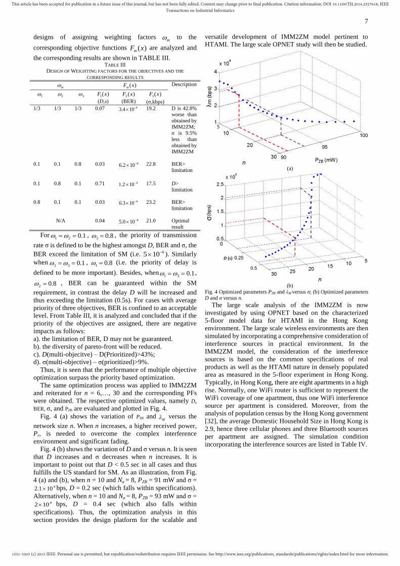
BER, σ, and PZB are evaluated and plotted in Fig. 4.
Fig. 4 (a) shows the variation of PZB and M versus the
network size n. When n increases, a higher received power,
Pr, is needed to overcome the complex interference
environment and significant fading.
Fig. 4 (b) shows the variation of D and σ versus n. It is seen
that D increases and σ decreases when n increases. It is
important to point out that D < 0.5 sec in all cases and thus
fulfills the US standard for SM. As an illustration, from Fig.
4 (a) and (b), when n = 10 and Na = 8, PZB = 91 mW and σ = 4102.1 bps, D = 0.2 sec (which falls within specifications).
Alternatively, when n = 10 and Na = 8, PZB = 93 mW and σ = 4102 bps, D = 0.4 sec (which also falls within
specifications). Thus, the optimization analysis in this
section provides the design platform for the scalable and
versatile development of IMM2ZM model pertinent to
HTAMI. The large scale OPNET study will then be studied.
(a)
(b)
Fig. 4 Optimized parameters PZB and λM versus n; (b) Optimized parameters
D and σ versus n.
The large scale analysis of the IMM2ZM is now
investigated by using OPNET based on the characterized
5-floor model data for HTAMI in the Hong Kong
environment. The large scale wireless environments are then
simulated by incorporating a comprehensive consideration of
interference sources in practical environment. In the
IMM2ZM model, the consideration of the interference
sources is based on the common specifications of real
products as well as the HTAMI nature in densely populated
area as measured in the 5-floor experiment in Hong Kong.
Typically, in Hong Kong, there are eight apartments in a high
rise. Normally, one WiFi router is sufficient to represent the
WiFi coverage of one apartment, thus one WiFi interference
source per apartment is considered. Moreover, from the
analysis of population census by the Hong Kong government
[32], the average Domestic Household Size in Hong Kong is
2.9, hence three cellular phones and three Bluetooth sources
per apartment are assigned. The simulation condition
incorporating the interference sources are listed in Table IV.

1551-3203 (c) 2015 IEEE. Personal use is permitted, but republication/redistribution requires IEEE permission. See http://www.ieee.org/publications_standards/publications/rights/index.html for more information.
This article has been accepted for publication in a future issue of this journal, but has not been fully edited. Content may change prior to final publication. Citation information: DOI 10.1109/TII.2016.2527618, IEEETransactions on Industrial Informatics
8
TABLE IV
WIRELESS ENVIRONMENT DESIGN IN OPNET SIMULATION
Description Assigned values according to findings from
feasibility testing in a prior experiment
WiFi Bluetooth Cellular Phone
signal
Number of
interference
sources per floor
8
24
24
Interference
sources
1 router per
apartment
3 nodes per
apartment
3 devices per
apartment (3G:LTE=2:1)
Power level of each
interference
source
20 dBm
4 dBm
33 dBm (3G) 27 dBm (LTE)
Wireless
standards
IEEE 802.11n
IEEE 802.15.1 3G & LTE
Modulation
QPSK GFSK EDGE
Frequency
channels
Randomly
assigned
channels (2.4 – 2.4835 GHz
from CH 1 to
CH 13)
Randomly
assigned
channels (2.4 – 2.4835 GHz
from CH1 to
CH 79)
Randomly
assigned in
UMTS frequency
bands (2.1
GHz as central frequency
with CH 1 to
CH 26)
It was captioned that the interference will cause delay
overshoot and thus the IMM2ZM will activate “Channel
Swapping”. Define Tcs as the “Channel Swapping Time” for
the duration of channel swapping. Fig. 5 shows the simulated
results (from OPNET) of D against time for n =5, 10, 20, 30
under the wireless environment shown in Table IV. Fig. 5
reveals that, at the turn of the IMM2ZM, there is an unstable
period of delay overshoot due to Tcs. It is seen that Tcs = 21
sec, 25 sec, 30 sec, 80 sec for n = 5, 10, 20, 30 respectively.
The delay overshoot aims at combating interference and is
mainly caused by channel swapping. After the lapse of delay
overshoot (Tcs), the transmission remains stable, hence
signifying that the channel swapping process has been
completed. It is seen that Tcs increases significantly with an
increasing n due to the large network cluster size in HTAMI,
thus requiring long transmission time between nodes. It is
also observed that when the number of interference sources
increases or when PZB is smaller, Tcs increases.
Fig. 5 Simulated D for n = 5, 10, 20, 30 by OPNET.
Define PRX as the receiving sensitivity of the IMM2ZM.
PRX is related to the gains and losses incurred in the link
budget, the transmitting power of interference sources and its
associated distance, as well as the distance away from
interference sources. PRX is expressed as:
RXTXIFSRXTXZBRX LLLLGGPdBmP )( (27)
where PZB, GTX and GRX are captioned Table I. LFS (dBm) is
the path loss and fading, which is related to the transmission
distance and wavelength. LI (dBm) refers to the loss due to
interference and LTX (dBm) and LRX (dBm) are the transmitter
loss and receiver loss respectively. It can be concluded from
(27) that PRX increases with an increasing PZB or a hardware
design of larger GTX and GRX. However, with fixed LTX and
LRX, as well as LFS, PRX certainly decreases tremendously due
to serious interference.
The relationship of Tcs versus n and PRX is plotted in Fig. 6
using OPNET when PZB = -20 dBm to 20 dBm and n = 1 to 30.
From Fig. 6, it is seen that PRX and n affect Tcs significantly.
When n increases, Tcs increases significantly because the
channel swapping process necessitates time to detect channel
condition and reiterates network traffics information between
RC and RMT in high traffics networks in HTAMI. The
improvement of PRX will reduce Tcs. It is evaluated that when
PRX = -12 dBm, Tcs will be increased tremendously because
of the link budget reaches the bottom margin of the
sensitivity of the IMM2ZM.
Fig. 6 Relationship between Tcs and n, PRX.
VI. ANALYSIS AND EVALUATION
To investigate the performance of IMM2ZM, an
interference mitigation study and a latency study were
conducted. It was shown that the latency study accounted for
the IMM2ZM system performance.
A. Interference Mitigation Study
Interference under high traffic condition weakens signal
reception. However, the potential interference cannot be
ignored for high rises as a result of the ever increasing
number of wireless users. As a result, interference mitigation
is important for high performance and thus a study is a
necessary.
With the experimental setup shown in Fig. 2, the
interferers were established in the vicinity of the RMT. The
RMT was located in the meter room and the access point
operated at the same frequency channel as the operating
channel of IMM2ZM. During the experiment, D and Tcs were
measured for meter reading collection. In order to investigate
a comprehensive performance of IMM2ZM, five buildings
with n = 3, 4, 5 respectively were measured. The results are
presented in Fig. 7.
Fig. 7 (a), (b), (c) depict the real time performance of D
with the introduction of interferers into buildings for n = 3, 4
and 5 respectively. On each floor, the real time delays of a
maximum of 10 individual hops (referred as
“Hop_<floor_No.>_<hop_No.>”) are recorded and analyzed.

1551-3203 (c) 2015 IEEE. Personal use is permitted, but republication/redistribution requires IEEE permission. See http://www.ieee.org/publications_standards/publications/rights/index.html for more information.
This article has been accepted for publication in a future issue of this journal, but has not been fully edited. Content may change prior to final publication. Citation information: DOI 10.1109/TII.2016.2527618, IEEETransactions on Industrial Informatics
9
It is seen that D increases by 60% - 70% between t = 0 and t =
5 sec for n = 3, 4 and 5. Such a performance is trivial since
IMM2ZM collects meter readings using a single channel.
The channel swapping period ends at t = 15 sec, 20 sec, 25
sec for n = 3, 4, 5 respectively and D becomes relatively
constant afterward. This phenomenon is attributed to the fact
that the IMM2ZM has successfully found a channel with
insignificant interference for transmission. When CSTt ,
the delay is high since data delivery enters the overshoot
period. When CSTt , D returns to a stable lower value. As
an illustration for analysis, Tcs (n=5) = 25 sec is longer than Tcs
(n=3) and Tcs (n=4) by 10 sec and 5 sec respectively. Thus a
larger network obviously occupies a longer swapping period,
rendering a higher delay. Nevertheless, for all scenarios,
IMM2ZM recovers its normal transmission after channel
swapping is completed. It is noted that Tcs is relatively small
with respect to the data collection period (i.e. 15-30 min
typically). Therefore, an IMM2ZM with small Tcs generally
is a figure of merit reflecting a robust HTAMI.
(a)
(b)
(c)
Fig. 7 (a) Real time D under interference for n = 3 when the maximum of hop = 10; (b) Real time D under interference for n = 4 when the maximum of hop
= 10; (c) Real time D under interference for n = 5 when the maximum of hop
= 10.
B. Latency study
In this investigation, analysis of IMM2ZM with n = 5, 10,
20 and 30 have been studied to give a holistic view of the
effectiveness. The results of D and σ versus k (k = 1, 2, 3, 4)
are plotted in Fig. 8 and Fig. 9 respectively. The performance
improvement of IMM2ZM (k = 4) (with interference
mitigation) over MIZBAN [8] (without interference
mitigation) is shown in Fig. 10.
Fig. 8 Investigation of D when k = 1, 2, 3, 4.

1551-3203 (c) 2015 IEEE. Personal use is permitted, but republication/redistribution requires IEEE permission. See http://www.ieee.org/publications_standards/publications/rights/index.html for more information.
This article has been accepted for publication in a future issue of this journal, but has not been fully edited. Content may change prior to final publication. Citation information: DOI 10.1109/TII.2016.2527618, IEEETransactions on Industrial Informatics
10
Fig. 9 Investigation of σ when k = 1, 2, 3, 4.
Fig. 8 investigates the variation of D against n (n = 1~30)
and k (k = 1~4). In general, D increases as n increases since
the average number of hops for the routing path as well as the
traffic loading increases. In contrast, D decreases as k
increases because the traffic loadings can be shared by the
multiple operation channels. It is seen from Fig. 8 that the
improvement of D for 5-floor (n = 5) buildings is
approaching saturation when k = 2. At k = 2, the improvement
of D for 5-floor buildings is not significant when compared to
10-floor and 20-floor buildings. This findings are attributed
to the low density traffic characteristics at n = 5. Besides,
when k increases, in particular at k = 4, it is seen that the
probability of finding a busy channel for RMTs is extremely
low. The channel access delay will be minimized and thus D
reaches minimum.
Fig. 9 investigates the variation of σ against n (n = 5, 10, 20,
30) and k (k = 1, 2, 3, 4). In general, σ increases as k increases
since IMM2ZM transmits data in parallel via multiple
channels simultaneously.
Fig. 10 Performance improvement of IMM2ZM (k = 4) (with interference mitigation) over MIZBAN [12] (without interference mitigation).
The strength of IMM2ZM versus MIZBAN is now
analyzed. The maximum capacity should be examined and
thus k = 4 is investigated. Fig. 10 shows the performance
improvement of IMM2ZM (k = 4) (with interference
mitigation) over MIZBAN [8] (without interference
mitigation). From Fig. 10, it is seen that as n increases (n = 5,
10, 20, 30), σ increases from 174% when n = 5 to: 329%
when n = 10; 280% when n = 20; 274% when n = 30. It is
seen that the gradient increase of σ is tremendous from n=5 to
n=10. Thus, it is concluded that IMM2ZM performs very
well at increasing network size (say n = 30). The performance
of D is also investigated. It is seen, that the improvement of D
increases rapidly from 37% at n = 5 to: 72% when n = 10;
65% when n = 20; 56% when n = 30. Hence, it is concluded
that the performance of the optimized IMM2ZM well
surpasses MIZBAN. In Hong Kong, the Hong Kong Housing
Authority of the Census and Statistics Department of the
Government of Hong Kong [30] revealed that n ~ 12 in 2014.
Apparently n will increase significantly with urban
modernization in the future. From the analysis in the paper, it
is evidenced that the IMM2ZM should be adopted for high
performance HTAMI.
VII. CONCLUSION
Current smart metering (SM) solutions focus on low traffic
for individual houses. SM traffics are ever growing, in
particular for buildings in Asia. This paper proposes the
IMM2ZM, a new multi-objective optimization
interference-mitigated ZigBee based Advanced Metering
Infrastructure (AMI) as a smart metering solution for high
traffics data. The contribution of this paper is five-folded.
Firstly, a prior measurement was performed to obtain the
prime data (pertinent to its characteristics) for the
formulation of objective functions for the optimal solution at
large scale. Secondly, an interference mitigation model has
been derived. Thirdly, a customization to NSGA-II [26]
optimization has been developed. Fourthly, the OPNET
evaluation has been implemented for large scale analysis.
Fifthly, a channel swapping IMM2ZM system has been
implemented and analyzed for high traffics AMI.
The delay (D), BER (PER) and application layer transmission
rate (σ) are pertinent descriptors providing a holistic view of
the latency performance that take account of the total number
of hops and the interference mitigation. These indicative
figures have been optimized to synthesize the IMM2ZM
performance. The channel swapping time (Tcs) has been
analyzed. Tcs evaluates the efficiency of channel swapping,
hence giving an account of the latency performance of the
network due to interference. It is concluded that when the
IMM2ZM sensitivity (PRX) is less than -12 dBm, Tcs increases
tremendously.
1551-3203 (c) 2015 IEEE. Personal use is permitted, but republication/redistribution requires IEEE permission. See http://www.ieee.org/publications_standards/publications/rights/index.html for more information.
This article has been accepted for publication in a future issue of this journal, but has not been fully edited. Content may change prior to final publication. Citation information: DOI 10.1109/TII.2016.2527618, IEEETransactions on Industrial Informatics
11
It is important to highlight that the IMM2ZM achieves an
effective performance in a HTAMI and results in a significant
improvement in the performance of the application layer
transmission rate (σ) and the average delay (D). The
improvement figures are: σ > ~300% and D >70% in a
10-floor building; σ > ~280% and D >65% in a 20-floor
building; and σ > ~270% and D >56% in a 30-floor building.
Analysis also reveals that the IMM2ZM results in typically
less than 0.43 sec delay for a 30-floor building under
interference. Such figures have fulfilled the latency
requirement of less than 0.5 sec for SMs [28] in the USA.
Thus the IMM2ZM features a high traffics
interference-mitigated ZigBee Advanced Metering
Infrastructure solution.
ACKNOWLEDGEMENT
The support from the Wireless Sustainability Center of the
Department of Electronic Engineering, City University of
Hong Kong is gratefully acknowledged.
VIII. REFERENCE
[1] N. Liu, J. Chen, L. Zhu, J. Zhang and Y. He, “A Key Management
Scheme for Secure Communications of Advanced Metering
Infrastructure in Smart Grid”, IEEE Trans. Ind. Electron.,vol. 60, no. 10, 2012, pp. 4746-4756.
[2] V. C. Gungor, D. Sahin, T. Kocak, S. Ergut, C. Buccella, C. Cecati and
G. P. Hancke, “Smart Grid Technologies: Communication Technologies and Standards,” IEEE Trans. Ind. Informat., vol. 7, no. 4,
2011, pp. 529-539.
[3] M. E. Kantarci and H. T. Mouftah, “Wireless Sensor Networks for Cost-Efficient Residential Energy Management in the Smart Grid”,
IEEE Trans. Smart Grid, vol. 2, no. 2, 2011, pp. 314-325.
[4] V. C. Gungor and G. P. Hancke, “Industrial Wireless Sensor Networks: Challenges, Design Principles, and Technical Approaches,” IEEE
Trans. Ind. Electron., vol. 56, no. 10, 2009, pp. 4258-4265.
[5] U.S. Department of Energy. (2009, May 18). Locke, Chu Announce Significant Steps in Smart Grid Development. [Online]. Available:
http://www.energy.gov/news2009/7408.htm.
[6] B. Heile, “Smart Grids for Green Communications”, IEEE Wireless Comm., vol. 17, no. 3, 2010, pp. 4-6.
[7] P. Varahram and B. Ali, “A crest factor reduction scheme based on
recursive optimum frequency domain matrix”, IEEE Trans. Consum. Electron., vol. 60, no. 2, 2014, pp. 179-183.
[8] H. Y. Tung, K. F. Tsang, K. T. Chui, H. C. Tung, H. R. Chi, G. P.
Hancke and K. F. Man, "The generic design of a high-traffic advanced metering infrastructure using ZigBee", IEEE Trans. Ind. Informat., vol.
10, no. 1, 2014, pp. 836-844.
[9] K. Deb, Search Methodologies, New York: Springer-Verlag, 2014, ch. 15.
[10] T. M. Chan, K. F. Man, K. S. Tang and S. Kwong, “A Jumping-Genes
Paradigm for Optimizing Factory WLAN Network”, IEEE Trans. Ind. Informat., Vol. 3, no. 1, 2007, pp. 33-43.
[11] K. Deb, A. Pratap, S. Agarwal and T. Meyarivan, “A Fast and Elitist
Multiobjective Genetic Algorithm: NSGA-II”, IEEE Trans. Evol. Comput., Vol. 6, no. 2, 2002, pp. 182-197.
[12] X. Zhang and K. G. Shin, “Cooperative Carrier Signaling:
Harmonizing Coexisting WPAN and WLAN Devices”, IEEE/ACM Trans. Networking, vol. 21, no. 2, 2012, pp. 426-439.
[13] P. Yi, A. Iwayemi and C. Zhou, “Developing ZigBee Deployment Guideline Under WiFi Interference for Smart Grid Applications”,
IEEE Trans. Smart Grid, vol. 2, no. 1, 2011, pp. 110-120.
[14] A. Mukherjee and A. L. Swindlehurst, “Robust Beamforming for Security in MIMO Wiretap Channels With Imperfect CSI”, IEEE
Trans. Signal Processing, vol. 59, no. 1, 2010, pp. 351-361.
[15] E. Toscano and L. L. Bello, “Multichannel Superframe Scheduling for IEEE 802.15.4 Industrial Wireless Sensor Networks”, IEEE Trans.
Ind. Informat., vol. 8, no. 2, 2012, pp. 337-350.
[16] I. Ho, P. Lam, P. Chong and S. Liew, “Harnessing the High Bandwidth of Multi-radio Multi-channel 802.11n Mesh Networks”, IEEE Trans.
Mobile Comp., vol. 13, no. 2, 2013, pp. 448-456.
[17] M. K. Denko, T. Jun, T. Nkwe and M.S. Obaidat, “Cluster-Based
Cross-Layer Design for Cooperative Caching in Mobile Ad Hoc Networks,” IEEE Syst. Journal, vol. 3, no. 4, 2009, pp 499-508.
[18] C. E. A. Campbell, K. K. Loo, H. A. Kurdi and S. Khan, “Comparison
of IEEE802.11 and IEEE 802.15.4 for Future Green Multichannel Multi-radio Wireless Sensor Networks”, IJCNIS, Vol. 3, No. 1, 2011,
pp. 96-103.
[19] Z. Liu and W. Wu, “A Dynamic Multi-radio Multi-channel MAC Protocol for Wireless Sensor Networks”, Proc. of ICCSN '10, 2010,
pp.105-109.
[20] S. Y. Shin, H. S. Park, S. H. Choi and W. H. Kwon, “Packet Error Rate Analysis of ZigBee Under WLAN and Bluetooth Interferences”, IEEE
Trans. Wireless Comm., vol.6, no.8, 2007, pp.2825-2830.
[21] K. F. Tsang, H. Y. Tung and K. L. Lam, ZigBee: From Basics to Designs and Applications, Prentice Hall, 2009, ch. 3.
[22] S. Y. Shin, S. Choi, H. S. Park and W. H. Kwon, “Lecture Notes in
Computer Science: Packet Error Rate Analysis of IEEE 802.15.4 Under IEEE 802.11b Interference”, Springer, 2005, ch. 4.
[23] G. Casella and R. L. Berger, “Statistical Inference”, Duxbury, 2001, pp.
159. [24] J. W. Chong, H. Y. Hwang, C. Y. Jung and D. K. Sung, “Analysis of
throughput in a ZigBee network under the presence of WLAN
interference”, Proc. of SCIT '07, 2007, pp.1166-1170.
[25] K. F. Tsang, Wireless Communication, Pearson, 2007, ch. 4.
[26] K. S. Tang, T. M. Chan, R. J. Yin and K. F. Man, Multiobjective
Optimization Methodology - A Jumping Gene Approach, CPC Press, 2012, ch. 2.
[27] OPNET University Program: http://www.opnet.com/services/university/
[28] Magazine of department of energy communications, USA
Communications requirements of smart grid technologies, Oct. 5, 2010.
[29] G. Anastasi, M. Conti and M. D. Francesco, “A Comprehensive
Analysis of the MAC Unreliability Problem in IEEE 802.15.4 Wireless Sensor Networks”, IEEE Trans. Ind. Informat., vol. 7, no.1, 2010, pp.
52-65.
[30] Hong Kong Housing Authority, (2015, Jan 28). Sustainability Report 2013/14. [Online]. Available:
http://www.housingauthority.gov.hk/mini-site/hasr1314/en/common/i
ndex.html. [31] Hong Kong Digest of Statistics, (2012, Apr), Trends in Population and
Domestic Households in Hong Kong. [Online]. Available:
http://www.census2011.gov.hk/pdf/Feature_articles/Trends_Pop_DH.
Hao Ran Chi (S’14) obtained the
Bachelor of Engineering in Electronic
and Communication Engineering with
First Class Honor from City University
of Hong Kong, in 2013. Currently, he is
studying for the Doctor of Philosophy at
the same university.
His research internets include artificial
intelligence, Optimization algorithms,
control systems and wireless network.
Kim Fung Tsang (M’95–SM’14)
obtained the Ph.D. from the University
of Wales, College of Cardiff. During
1983-88, he has been a Research
Assistant and a Product Executive. In
March 1988, he joined the City
University of Hong Kong. Dr. Tsang is
now an Associate Professor in the

1551-3203 (c) 2015 IEEE. Personal use is permitted, but republication/redistribution requires IEEE permission. See http://www.ieee.org/publications_standards/publications/rights/index.html for more information.
This article has been accepted for publication in a future issue of this journal, but has not been fully edited. Content may change prior to final publication. Citation information: DOI 10.1109/TII.2016.2527618, IEEETransactions on Industrial Informatics
12
Department of Electronic Engineering.
His current research interests include radio frequency circuit
design, mobile communication network design, and energy
management and wireless automation protocol design.
Kwok Tai Chui (S’14) received the
Bachelor of Engineering in Electronic
and Communication Engineering
(Business Intelligence Minor) with first
class honor from City University of
Hong Kong, in 2013. Currently, he is
studying Ph.D. degree at the same
university.
His research interest includes wireless communication,
pattern recognition, health analysis and machine learning
algorithms.
Henry Shu-Hung Chung (M’95–
SM’03–F’16) received the B.Eng.
degree in 1991 and the Ph.D. degree in
1994 in electrical engineering, both from
The Hong Kong Polytechnic University,
Hong Kong. Since 1995, he has been
with the City University of Hong Kong
(CityU), Hong Kong. He is currently a
Professor at the Department of
Electronic Engineering, and the Director of the Centre for
Smart Energy Conversion and Utilization Research.
His research interests include time- and frequency-domain
analysis of power electronic circuits, switched
capacitor-based converters, random-switching techniques,
control methods, digital audio amplifiers, soft-switching
converters, and electronic ballast design.
Bingo Wing Kuen Ling (M’08–SM’08) received the B.Eng. (Hons) and M.Phil.
degrees from the department of
Electronic and Computer Engineering,
the Hong Kong University of Science
and Technology, in 1997 and 2000,
respectively, and the Ph.D. degree in the
department of Electronic and
Information Engineering from the Hong
Kong Polytechnic University in 2003. In 2004, he joined the
King’s College London as a Lecturer. In 2010, he joined the
University of Lincoln as a Principal Lecturer and promoted to
a Reader in 2011. In 2012, he joined the Guangdong
University of Technology as a Full Professor.
His research interests include time frequency analysis and
applications, optimization for life science, symbolic
dynamics, fractal and chaos and control theories.
Loi Lei Lai (M’87–SM’92–F’07) received the B.Sc. (first class Hons.)
and Ph.D. degrees in electrical
engineering from Aston University,
Birmingham, U.K., in 1980 and 1984,
respectively. Currently, he is a
Director of Energy Strategy, Planning,
Policy Support, Research, and
Development Centre, State Grid
Energy Research Institute, Beijing, China. He was a Chair
in Electrical Engineering with City University London,
London, U.K. Dr. Lai is a Fellow of the Institution of
Engineering and Technology (IET), U.K. He is also a
National Distinguished Expert in China. He was the
recipient of the Prize Paper Award by the IEEE/Power and
Energy Society Energy Development and Power
Generation Committee in 2006 and 2009, and also was
awarded a higher Doctorate, D.Sc. degree, by the City
University of London.