interfacing electrochromic spectacles to computer io ports
TRANSCRIPT
U T T E R W 0 R T H I N E M A N N
Interfacing electrochromic spectacles to computer IO ports David N.J. White and Lesley Bissland
Department of Chemistry, University of Glasgow, Glasgow G12 8QQ, Scotland
Many important properties of molecules depend on their precise three-dimensional (3D) structure. It is therefore useful to be able to view a molecule in 3D on a 2D computer screen when manipulating it. An inexpensive method for viewing in 3D using liquid crystal glasses and a PC is presented. The methodology used is easily extended to other computers and workstations.
Keywords: liquid crystal glasses, stereoscopy, PC card.
I N T R O D U C T I O N
Although red/green stereo is a fairly simple and inexpensive method for viewing in three dimensions (3D), the images produced are monochromatic. This loss of color can be important in many cases. For example, when viewing a molecule, color coding can be used to signify different atom types. Full-color clear 3D images can be obtained by using liquid crystal glasses. These glasses are generally expen- sive; ( -£1000) however, by using SEGA video game liquid crystal glasses ( -£70) the cost can be cut dramatically.
Chelvanayagam and McKeaig t described a method for stereo viewing using the SEGA glasses. Their approach involved modifying the existing SEGA circuit board and connecting a line to the DO pin on a PC parallel port to toggle the glasses. Although this approach is perfectly sat- isfactory a number of people have reported to the authors that they have been unable to make the modified SEGA circuit board work. To circumvent these problems this ar- ticle contains a full circuit diagram of the SEGA control circuit and describes an alternative control circuit built on a PC plug-in card.
STEREOSCOPY Binocular stereoscopy is a method of generating pairs of two-dimensional images that deceive the human eye and brain into perceiving a three-dimensional image. The pairs of images can be generated either side by side or full screen sequentially on the computer screen. The second image is
Address reprint requests to Dr. White, Department of Chemistry, Univer- sity of Glasgow, Glasgow Gl2 8QQ, Scotland. Received 12 April 1994; revised 3 June 1994; accepted 7 June 1994.
generated from the first by a rotation of 2-6 ° around the y axis (x axis horizontal, y axis vertical, both in the plane of the screen). Various methods are employed to ensure that the left eye sees only one of the images and the right eye only the other. The images can be either stationary or rotating.
The method of stereoscopy used by the SEGA glasses is known as tachistoscopy. This is a binocular process in which the left and right eye images are displayed on the screen alternately and the view of each eye is obscured in synchronization with the display of the "wrong image." To achieve this, alternate lenses of the glasses are turned opaque at the appropriate moment by an electric field. The frequency of switching between images must be approxi- mately 40 Hz to obtain a flicker-free image.
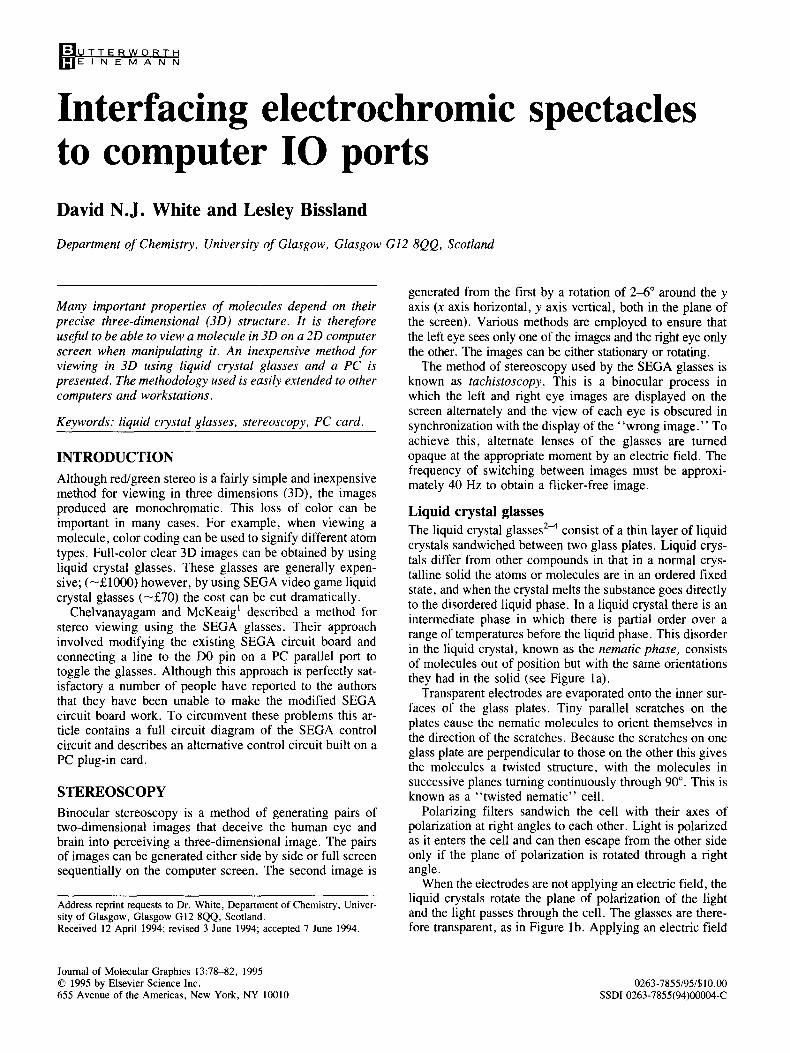
Liquid crystal glasses The liquid crystal glasses 2~ consist of a thin layer of liquid crystals sandwiched between two glass plates. Liquid crys- tals differ from other compounds in that in a normal crys- talline solid the atoms or molecules are in an ordered fixed state, and when the crystal melts the substance goes directly to the disordered liquid phase. In a liquid crystal there is an intermediate phase in which there is partial order over a range of temperatures before the liquid phase. This disorder in the liquid crystal, known as the nematic phase, consists of molecules out of position but with the same orientations they had in the solid (see Figure la).
Transparent electrodes are evaporated onto the inner sur- faces of the glass plates. Tiny parallel scratches on the plates cause the nematic molecules to orient themselves in the direction of the scratches. Because the scratches on one glass plate are perpendicular to those on the other this gives the molecules a twisted structure, with the molecules in successive planes turning continuously through 90 ° . This is known as a "twisted nematic" cell.
Polarizing filters sandwich the cell with their axes of polarization at right angles to each other. Light is polarized as it enters the cell and can then escape from the other side only if the plane of polarization is rotated through a right angle.
When the electrodes are not applying an electric field, the liquid crystals rotate the plane of polarization of the light and the light passes through the cell. The glasses are there- fore transparent, as in Figure lb. Applying an electric field
Journal of Molecular Graphics 13:78-82, 1995 © 1995 by Elsevier Science Inc. 655 Avenue of the Americas, New York, NY 10010
0263-7855/95/$10.00 SSDI 0263-7855(94)00004-C
Solid Phase Nematic Phase
I I i
PoIarisel
Unpolarised Ve~lcally Polansed Lightln Lght
Glass Plates
Ltght Polansatlon Rotated by 90 °
Polanser
Horizontally Polarised Light Out
C Polarlsel
/ ,
/ ! Unpolarised Verilcally Polarlsed Light In Light
Glass Plates
Molecules ahgned by field
Polm'iser
/
Vertically pola~ised hght blocked by polariset
Figure 1. (a) Liquid crystals; (b) twisted nematic cell; (c) cell with electric field on.
forces the molecules to lie parallel to it and to the direction of the light. The plane of polarization, which is at right angles to the direction of the light, is therefore unaffected by the molecules: it is not rotated and light cannot pass through the cell. This causes the glasses to become opaque as illustrated in Figure lc.
S E G A C I R C U I T
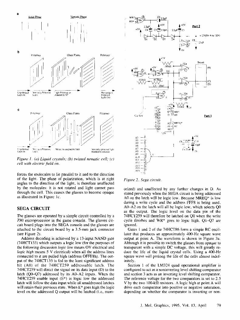
The glasses are operated by a simple circuit controlled by a Z80 microprocessor in the game console. The glasses cir- cuit board plugs into the SEGA console and the glasses are attached to the circuit board by a 3.5-mm jack connector (see Figure 2).
Address decoding is achieved by a 13-input NAND gate (74HCT 133) which outputs a logic low (for the purposes of the following discussion logic low means OV electrical and logic high means 5 V electrical) when all the address lines connected to it are pulled high (address OFFF8h). The out- put of the 74HCT133 is fed to the least significant address bit (A0) of the 74HCT259 addressable latch. The 74HCT259 will direct the signal on its data input (D) to the latch (Q0-Q7) addressed by its A0--A2 inputs. When the 74HCT259 enable input (E*) is logic low the addressed latch will follow the data input while all unaddressed latches will retain their previous state. When E* goes high the logic level on the addressed Q output will be latched (i.e, mere-
WR* 1 (~) C6 ~D* ~ I Z2~F I
... 2.2~.F_]_ i+5v ] ~+Sv Part2 I
D1 D2 D3 I34 ' 6 ~ 3 2 4 C 8 ~ ~ 7 27c, F
iov ' ~ +SV
+5V 100k~
f !
. : :
Cut tiere
A3 A4 A5 A6 A7 5z A8 - -- \ A9 - - ) 9 AI0 All AI2 AI3 A14 -- : AI5 1~
'133
Figure 2. Sega circuit.
Socket
i
12~_ --c~,~15 ~ 100kn ¥0V
,~Q6 E* ~-~ WR*
9 ~ j Part l Q3
~£Q~ A2 3 MREQ* ~ i AI--2~2 *-~Qo AO
'259 t+5V
C ~ 2 ~ E ~ n C 10 mL__ ~ l O g F
2 x 27nF W - - O V
orized) and unaffected by any further changes in D. As stated previously when the SEGA circuit is being addressed A0 on the latch will be logic low. Because MREQ* is low during a write cycle and the address FFF8 is being used, A0-A2 on the latch will all be logic low, which selects Q0 as the output. The logic level on the data pin of the 74HCT259 will therefore be latched on Q0 when the write cycle finishes and WR* goes to logic high. Q1-Q7 are ignored.
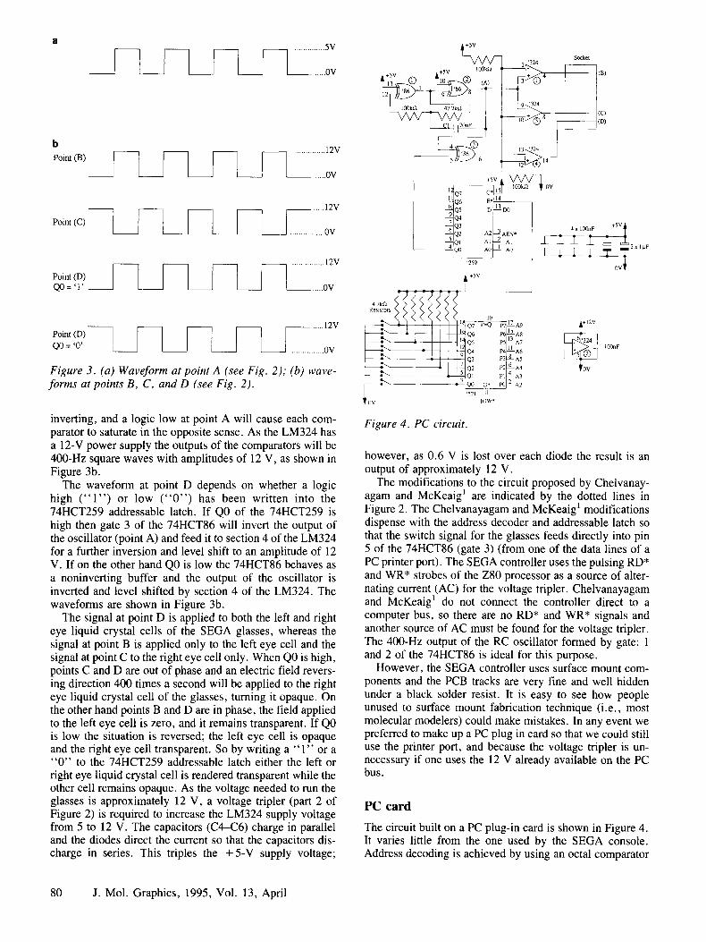
Gates 1 and 2 of the 74HCT86 form a simple RC oscil- lator that produces an approximately 400-Hz square wave output at point A. The waveform is shown in Figure 3a. Although it is possible to switch the glasses from opaque to transparent with a simple DC voltage, this will greatly re- duce the life of the liquid crystal cells. Using a 400-Hz square wave will prolong the life of the cells almost indef- initely.
Section 1 of the LM324 quad operational amplifier is configured to act as a noninverting level shifting comparator and section 3 acts as an inverting level shifting comparator. The reference voltage for the two comparators is set to 2.5 V by the two 100-kf~ resistors. A logic high at point A will drive each comparator into positive or negative saturation, depending on whether the comparator is inverting or non-
J. Mol. Graphics, 1995, Vol. 13, April 79
.............. 5V
..... 0V
b .............. 12V Point (B)
. . . . . . . 0V
Point (C)
. . . . . . 12V
J ................ 0V
............... 12V
Point (D) = , r _ _ . . . . . . ov
. . . . . . 12V Point (D) [
= ' 0 ' _ _ ................ 0V
Figure 3. (a) Waveform at point A (see Fig. 2); (b) wave- forms at points B, C, and D (see Fig. 2).
inverting, and a logic low at point A will cause each com- parator to saturate in the opposite sense. As the LM324 has a 12-V power supply the outputs of the comparators will be 400-Hz square waves with amplitudes of 12 V, as shown in Figure 3b.
The waveform at point D depends on whether a logic high ( " 1 " ) or low ( " 0 " ) has been written into the 74HCT259 addressable latch. If Q0 of the 74HCT259 is high then gate 3 of the 74HCT86 will invert the output of the oscillator (point A) and feed it to section 4 of the LM324 for a further inversion and level shift to an amplitude of 12 V. If on the other hand Q0 is low the 74HCT86 behaves as a noninverting buffer and the output of the oscillator is inverted and level shifted by section 4 of the LM324. The waveforms are shown in Figure 3b.
The signal at point D is applied to both the left and right eye liquid crystal cells of the SEGA glasses, whereas the signal at point B is applied only to the left eye cell and the signal at point C to the right eye cell only. When Q0 is high, points C and D are out of phase and an electric field revers- ing direction 400 times a second will be applied to the right eye liquid crystal cell of the glasses, turning it opaque. On the other hand points B and D are in phase, the field applied to the left eye cell is zero, and it remains transparent. If Q0 is low the situation is reversed; the left eye cell is opaque and the right eye cell transparent. So by writing a " 1 " or a " 0 " to the 74HCT259 addressable latch either the left or right eye liquid crystal cell is rendered transparent while the other cell remains opaque. As the voltage needed to run the glasses is approximately 12 V, a voltage tripler (part 2 of Figure 2) is required to increase the LM324 supply voltage from 5 to 12 V. The capacitors (C4-C6) charge in parallel and the diodes direct the current so that the capacitors dis- charge in series. This triples the +5-V supply voltage;
SV
VVV-- +5V +SV 100k.f2
Socket 2 '324 ~ (B)
÷ ~ ~ ~c/
~ (D)
13 '324
14
13D0
3AEN * . 4 x 100nF _+SV
T T T
+SV
I
h - ~ I I! 2 (~4 p4 l~-A6 100nF
h ~ ~ Q i P2 6~A4
T 0¥ lOW*
Figure 4. PC circuit.
however, as 0.6 V is lost over each diode the result is an output of approximately 12 V.
The modifications to the circuit proposed by Chelvanay- agam and McKeaig I are indicated by the dotted lines in Figure 2. The Chelvanayagam and McKeaig I modifications dispense with the address decoder and addressable latch so that the switch signal for the glasses feeds directly into pin 5 of the 74HCT86 (gate 3) (from one of the data lines of a PC printer port). The SEGA controller uses the pulsing RD* and WR* strobes of the Z80 processor as a source of alter- nating current (AC) for the voltage tripler. Chelvanayagam and McKeaig ~ do not connect the controller direct to a computer bus, so there are no RD* and WR* signals and another source of AC must be found for the voltage tripler. The 400-Hz output of the RC oscillator formed by gate: 1 and 2 of the 74HCT86 is ideal for this purpose.
However, the SEGA controller uses surface mount com- ponents and the PCB tracks are very fine and well hidden under a black solder resist. It is easy to see how people unused to surface mount fabrication technique (i.e., most molecular modelers) could make mistakes. In any event we preferred to make up a PC plug in card so that we could still use the printer port, and because the voltage tripler is un- necessary if one uses the 12 V already available on the PC bus.
PC card
The circuit built on a PC plug-in card is shown in Figure 4. It varies little from the one used by the SEGA console. Address decoding is achieved by using an octal comparator
80 J. Mol. Graphics, 1995, Vol. 13, April
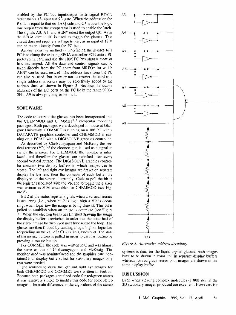
enabled by the PC bus input/output write signal IOW*, rather than a 13-input NAND gate. When the address on the P side is equal to that on the Q side and G* is low the logic low output from the comparator is used to enable the latch. The signals A0, A1, and AEN* select the output Q0. As in the SEGA circuit DO is used to toggle the glasses. This circuit does not require a voltage triplet, as an input of 12 V can be taken directly from the PC bus.
Another possible method of interfacing the glasses to a PC is to clamp the existing SEGA controller PCB onto a PC prototyping card and use the IBM PC bus signals more or less unchanged. All the data and control signals can be taken directly from the PC apart from MREQ* for which AEN* can be used instead. The address lines from the PC can also be used, but in order not to restrict the card to a single address, inverters may be selectively added to the address lines as shown in Figure 5. Because the usable addresses of the I/O ports on the PC lie in the range 0200- 3FF, A9 is always going to be high.
SOFTWARE
The code to operate the glasses has been incorporated into the CHEMMOD and COMMET 5-7 molecular modeling packages. Both packages were developed in house at Glas- gow University. COMMET is running on a 386 PC with a DATAPATH graphics controller and CHEMMOD is run- ning on a PC/AT with a DIGISOLVE graphics controller.
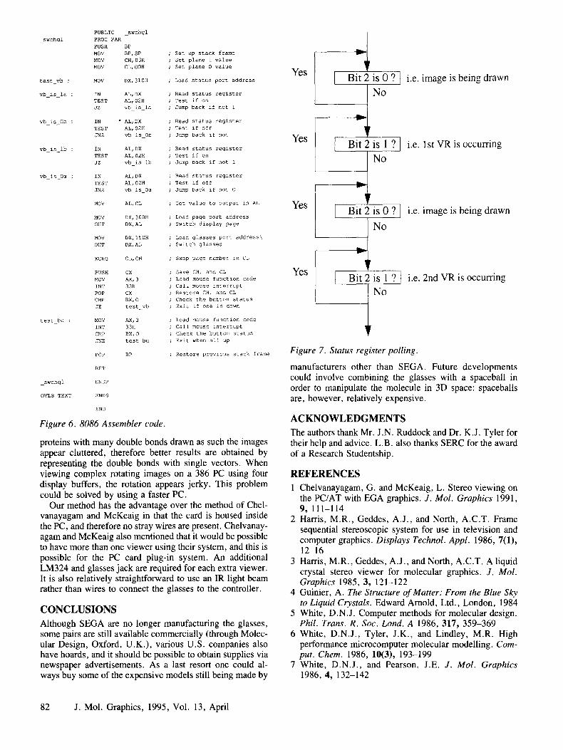
As described by Chelvanayagam and McKeaig the ver- tical retrace (VR) of the electron gun is used as a signal to switch the glasses. For CHEMMOD the monitor is inter- laced, and therefore the glasses are switched after every second vertical retrace. The DIGISOLVE graphics control- ler contains two display buffers in which images can be stored. The left and right eye images are drawn on separate display buffers and then the contents of each buffer are displayed on the screen alternately. Code to poll the bit in the register associated with the VR and to toggle the glasses was written in 8086 assembler for CHEMMOD (see Fig- ure 6).
Bit 2 of the status register signals when a vertical retrace is occurring (i.e., when bit 2 is logic high a VR is occur- ring, when logic low the image is being drawn). This bit is polled to establish when an image is complete (see Figure 7). When the electron beam has finished drawing the image the display buffer is switched in order that the other half of the stereo image be displayed next time round the loop. The glasses are then flipped by sending a logic high or logic low (depending on the value in CL) to the glasses port. The state of the mouse buttons is polled in order to exit the routine by pressing a mouse button.
For COMMET the code was written in C and was almost the same as that of Chelvanayagam and McKeaig. The monitor used was noninterlaced and the graphics card con- tained four display buffers, but for stationary images only two were needed.
The routines to draw the left and right eye images for both CHEMMOD and COMMET were written in Fortran. Because both packages contained code for red/green stereo it was relatively simple to modify this code for color stereo images. The main difference in the algorithms of the stereo
A3 ~ ° ° I I
A4 ~) o o
A5 ~ o o 1 ]
A6 ~ o o !
A7 ~ o e
A8 ~ o o
A9
T \ P
T 1/
w
'133
Figure 5. Alternative address decoding.
systems is that, for the liquid crystal glasses, both images have to be drawn in color and in separate display buffers whereas for red/green stereo both images are drawn in the same display buffer.
DISCUSSION Even when viewing complex molecules (1 800 atoms) the 3D stationary images produced are excellent. However, for
J. Mol. Graphics, 1995, Vol. 13, April 81
PUBLIC _swchgl
_swchgl PROC FAR
PUSH BP
MOV BP, SP MOV CH, 03H
MOV CL,OOH
test vb : MOV DX,310H
vb_isla : IN AL, DX TEST AL, 02H
JZ vb_is_la
vb_isOb : IN " AL, DX
TEST AL, 02H
JNZ vb is Ob
vbislb : IN AL, DX TEST AL,02H
JZ vb is lb
vb is Oa : IN AL, DX
TEST AL,02H
JNZ vb is Oa
MOV AL, CL
MOV DX, 300H
OUT DX, AL
MOV DX, 150H
OUT DX,AL
XCHG CL, CH
PUSH CX
MOV AX,3
INT 33H POP CX
CMP BX, O JE test vb
test bu : MOV AX,3
INT 33H CMP BX,O
JNE test bu
POP BP
RET
_swohgl ENDP
OVL8 TEXT ENDS
END
Figure 6. 8086 Assembler code.
Set up stack frame Set plane 1 value
Set plane O value
Load status port address
Read status register Test if on
Jump back if not 1
Read status register
Test if off Jump back if not
Read status register
Test if on
Jump back if not 1
Read status register
Test if off
Jump back if not O
Get value to output in AL
Load page port address
Switch display page
Load glasses port address\
Switch glasses
Swap page number in CL
Save CH, and CL
Load mouse function code
Call mouse interrupt
Restore CH, and CL Check the button stat~s Exit if one is down
Load mouse function code
Call mouse interrupt
Check the button status
Exit when all up
Restore previous stack frame
proteins with many double bonds drawn as such the images appear cluttered, therefore better results are obtained by representing the double bonds with single vectors. When viewing complex rotating images on a 386 PC using four display buffers, the rotation appears jerky. This problem could be solved by using a faster PC.
Our method has the advantage over the method of Chel- vanayagam and McKeaig in that the card is housed inside the PC, and therefore no stray wires are present. Chelvanay- agam and McKeaig also mentioned that it would be possible to have more than one viewer using their system, and this is possible for the PC card plug-in system. An additional LM324 and glasses jack are required for each extra viewer. It is also relatively straightforward to use an IR light beam rather than wires to connect the glasses to the controller.
CONCLUSIONS Although SEGA are no longer manufacturing the glasses, some pairs are still available commercially (through Molec- ular Design, Oxford, U.K.), various U.S. companies also have hoards, and it should be possible to obtain supplies via newspaper advertisements. As a last resort one could al- ways buy some of the expensive models still being made by
Yes
Yes
Yes
Yes
h , . . _
I Bit 2 is 0 ? [ i.e. image is being drawn ,,.._ N o
-+ Bit 2 is 1 ? [ i.e. 1 st VR is occurring
No
3 Bit 2 is 0 ? I i.e. image is being drawn
,,.._ N o
Bit 2 is 1 ? I i.e. 2nd VR is occurring
Figure 7. Status register polling.
manufacturers other than SEGA. Future developments could involve combining the glasses with a spaceball in order to manipulate the molecule in 3D space: spaceballs are, however, relatively expensive.
ACKNOWLEDGMENTS The authors thank Mr. J.N. Ruddock and Dr. K.J. Tyler for their help and advice. L.B. also thanks SERC for the award of a Research Studentship.
REFERENCES 1 Chelvanayagam, G. and McKeaig, L. Stereo viewing on
the PC/AT with EGA graphics. J. Mol. Graphics 1991, 9, 111-114
2 Harris, M.R., Geddes, A.J., and North, A.C.T. Frame sequential stereoscopic system for use in television and computer graphics. Displays Technol. Appl. 1986, 7(1), 12-16
3 Harris, M.R., Geddes, A.J., and North, A.C.T. A liquid crystal stereo viewer for molecular graphics. J. Mol. Graphics 1985, 3, 121-122
4 Guinier, A. The Structure of Matter: From the Blue Sky to Liquid Crystals. Edward Arnold, Ltd., London, 1984
5 White, D.N.J. Computer methods for molecular design. Phil. Trans. R. Soc. Lond. A 1986, 317, 359-369
6 White, D.N.J., Tyler, J.K., and Lindley, M.R. High performance microcomputer molecular modelling. Com- put. Chem. 1986, 10(3), 193-199
7 White, D.N.J., and Pearson, J .E .J . Mol. Graphics 1986, 4, 132-142
82 J. Mol. Graphics, 1995, Vol. 13, April