interface design for unmanned vehicle supervision through ... · interface design for unmanned...
TRANSCRIPT

Interface Design for Unmanned Vehicle Supervisionthrough Hybrid Cognitive Task Analysis
Jamie C. Macbeth1, M. L. Cummings1, Luca F. Bertuccelli2, Amit Surana2
1Humans and Automation Laboratory, Massachusetts Institute of Technology, Cambridge, MA2United Technologies Research Center, East Hartford, CT
While there is currently significant interest in developing Unmanned Aerial Systems (UASs) that can besupervised by a single operator, the majority of these systems focus on Intelligence, Surveillance, and Re-connaissance (ISR) domains. One domain that has received significantly less attention is the use of multipleUASs to insert or extract supplies or people. To this end, MAVIES (Multi-Autonomous Vehicle Insertion-Extraction System) was developed to allow a single operator the ability to supervise a primary cargo Un-manned Aerial Vehicle (UAV) along with multiple scouting UAVs. This paper will detail the developmentof the design requirements generated through a Hybrid Cognitive Task Analysis (hCTA) and the display thatresulted from these efforts. A major innovation in the hCTA process in this effort was the alteration of thetraditional decision ladder process to specifically identify decision-making tasks that must be augmented withautomation.
INTRODUCTION
Current-day Unmanned Aerial Systems (UASs) realize thevision of the pilotless remote-controlled aircraft that observesthe world at a great distance. However, one projected evolu-tion of these systems is extending to missions where an Un-manned Aerial Vehicle (UAV) is able to land in a hostile ordangerous environment and insert or extract cargo or personnel.Additionally, high level control of UASs from manned aircraftis expected to extend the range of these systems and improveoperational teaming between manned and unmanned vehicles(United States Army, 2010). This work, a collaboration betweenthe MIT Humans and Automation Laboratory and United Tech-nologies Research Center (UTRC), focused on the developmentof a human operator interface for controlling multiple, hetero-geneous UAVs in insertion and extraction missions.
In this scenario, the human user of the Multi-AutonomousVehicle Insertion-Extraction System (MAVIES) supervises aCargo UAV (CUAV) and two Scout UAVs (SUAVs) using apoint-and-click graphical user interface. The task environmentfor insertion-extraction missions is assumed to be dynamic andrapidly changing. The general class of insertion-extraction mis-sions includes both military and civilian scenarios, such ascargo resupply, medical evacuation, search and rescue, and tac-tical firefighting. To generate display information requirementsfor the MAVIES interface, a Hybrid Cognitive Task Analysis(hCTA) was performed. This analysis method derives the in-formation requirements of the human interface from a set ofoperational tasks.
HYBRID COGNITIVE TASK ANALYSIS
The development of futuristic human interfaces poses achicken-or-egg conundrum when the designers of a system seekto analyze a domain in order to derive interface design con-cepts, but no interface has ever been designed for the domain.In cases where no previous implementations of an interface ex-ist, the hCTA extends traditional cognitive task analysis meth-ods to generate information and functional requirements using
a scenario description and an enumeration of high-level missiongoals. This method of analysis has four steps:
1. Generate a scenario task overview,2. Generate an event flow diagram,3. Create decision ladders for critical decisions, and4. Generate situation awareness requirements.
The hCTA method (Nehme, Scott, Cummings, & Furusho,2006) has previously been used to generate functional and in-terface requirements for the supervisory control of multiple,heterogeneous unmanned vehicles (Scott & Cummings, 2006),for a mobile interface for utility repair workers (Tappan, Cum-mings, Mikkelsen, & Driediger, 2011), and for the developmentof an interactive in-cab scheduling interface for railroad loco-motive operators (Tappan, Pitman, Cummings, & Miglianico,2011).
Scenario Task Overview
The purpose of the initial step in the hCTA process, gen-erating the scenario task overview, is to capture a more formaldefinition of the mission statement in terms of phases, repre-senting high-level groupings of tasks, and of the tasks in eachphase. The phases and tasks are oriented to particular goals andsubgoals in the mission.
For MAVIES, five phases were specified for a single useroperator controlling multiple UAVs in an insertion-extractionmission. They were named Mission Assignment, Takeoff, EnRoute, Insertion-Extraction, and Return to Base. In the Mis-sion Assignment phase, the operator receives a mission, requestssupport, and prepares for mission commencement. At the Take-off phase, the operator launches scout UAVs to determine asafe path and landing site for the CUAV. Then the CUAV takesoff, beginning the En Route phase, where the user monitors theCUAV’s progression to the landing site and the SUAVs escortthe CUAV if needed. During Insertion-Extraction, the CUAVlands at the designated site, performs the on- and/or off-loadingobjective of the mission, and subsequently takes off. During thistime, the SUAVs survey the area to assure the CUAV’s safety

Information-processingactivity
Knowledge produced byinformation-processing
activity
Information-processingactivitywith automation
AutomationLevels
Figure 1: A legend for the decision ladder diagrams generated as part of the hCTA process. The practice innovation in the hCTA processfor MAVIES was the identification of human information-processing activities aided by automation.
during insertion-extraction, and to determine a safe path backto base. During the Return to Base phase, the operator moni-tors the CUAV’s safe travel home to end the mission, with theSUAVs again escorting the CUAV if necessary. Twenty-eighthigh-level tasks were specified at this stage, ordered temporallywithin their respective phases, and labeled “continuous” or “se-quential.”
Operational Event Flow
In the next step of the design process, an event flow dia-gram was generated, providing a finer level of specification ofoperator tasks that eventually produce a set of informational re-quirements for the user interface. The diagram is effectivelya flowchart of the operator’s execution of a task, and such aflowchart was created to represent each mission phase identi-fied in the scenario task overview.
Process, decision and loop blocks in the event flow diagramare labeled with alphanumeric codes so that they can be cross-referenced throughout the rest of the hCTA process. The labelsconsist of a single letter (P for processes, D for decisions, L forloops) and a number. Ninety-one blocks were created in gen-erating the event flow diagram for MAVIES. In addition to the5 phases previously mentioned, there were also 3 continuousmonitoring blocks, representing processes that must occur si-multaneously throughout each of the 5 phases. Each continuousmonitoring loop has a process that could interrupt the normaltask flow in an emergent situation—such as a UAV being lowon fuel. The 91 total blocks included 39 processes, 14 loops,and 20 decision blocks.
Decision Ladders
In order to determine what information is required fordecisions, a structure called a Decision Ladder (Rasmussen,Pejtersen, & Goodstein, 1994) was generated for each com-plex decision-making process identified in the operational eventflow.
Traditional decision ladders represent what informationprocesses need to occur, independent of who will perform a
task or how a particular control task will be accomplished (Ras-mussen, 1983). In the case of systems with computer-based de-cision support tools, the traditional decision ladder representsthe information processing activities and states of knowledgethat must be addressed by the tool whether or not a computer ora human makes the decision.
One advancement that this research effort makes over tra-ditional decision ladders is recognizing that such complex deci-sions involving multiple unmanned aerial vehicles must lever-age automation, at least at some level, to assist in the decisionmaking process. To that end, in the decision ladders for thishCTA, we introduce a new information processing activity thatis not agent independent.
In traditional decision ladders, an information-processingactivity is represented by a rectangle, and resulting knowledgestates in ovals (Figure 1). We propose that when a decisionmaker is faced with an information processing activity that re-quires optimizing several different variables, a task that is diffi-cult for humans when faced with a large decision space and timepressure, this activity should be explicitly represented by a rect-angle with a curved line (Figure 1). This shape indicates that ahuman will likely need some form of automation assistance dueto the complexity of the information processing activity.
Figure 2 shows a cutout of the decision ladder for the de-cision “Is There a Suitable Initial/Alternative Route” and illus-trates the decision ladder innovation in the application of thehCTA process for the MAVIES design. As part of the “Is Therea Suitable Initial/Alternative Route” decision task, the operatorsupplies a set of constraints, such as the allowable proximity ofhostiles and obstacles to the CUAV’s path. These constraintswill be used by the automation via an optimization process toevaluate the feasibility and safety of the possible routes.
With the help of an interactive visualization that allows theoperator to rapidly conduct what-if analysis in changing con-straints and variables of interest, the user processes informationabout the safety of routes and their efficiency in terms of fueland flight time. This particular decision ladder is annotatedwith shaded blocks that suggest different possible Levels OfAutomation (LOAs) (Sheridan & Verplank, 1978) that could beimplemented as decision support for the information processing

EVALUATE safety of route(s)(nearby hostile targets; proximity,number and heightof obstacles;cloud ceiling; visibility level;weather; divert landing sites
available)
List of constraints for routeselection
EVALUATE route efficiency (time togoal, total flight time, available fuel,current fuel level, estimated fuel
level, fuel surplus, length, restrictedarea avoidance)
ESTIMATE safety ofroute(s) over projected CUAVtraversal (location of nearby
hostile targets, troopmovement, weather forecast)
ORDER route(s) based onsatisfaction of route efficiency,safety, and estimated safetyover projected CUAV traversal
Satisfaction of routeefficiency, currentand
projected safety of route(s)
WHAT-IF TOOLAutomation helps human
compare the different routesbased on defined softconstraints (LOA 2)
ORAutomation compares the
different routes based on definedsoft constraints and makesrecommendations (LOA 4)
Possible CUAV route(s)identified byUAV(s)
CONFIRM route for CUAV
Suitable route(s)identified, furtheranalysis desired
No suitableroute
Route confirmed
Estimated safety of routeover projected CUAV
traversal
Prescriptive/Rational Decision-MakerRecommended
Descriptive/Naturalistic Decision-MakerAlternative
Skill Based
Rule Based
Knowledge Based
Efficiency of route
Routesuitable
Rule/Knowledge Based
ESTIMATE safety ofroute(s) over CUAV traversal(location of nearby hostiletargets, troopmovement,
weather forecast)
EVALUATE route efficiency (time togoal, total flight time, available fuel,current fuel level, estimated fuel levelby arrival time, fuel surplus, route
length and restricted area avoidance)
Information-processingactivity
Knowledge produced byinformation-processing
activity
LEGEND
Information-processingactivitywith automation
Ordered list of route(s)identifying optimal routebased on defined soft
constraints
EVALUATE safety of route(s)(nearby hostile targets; proximity,number and heightof obstacles;cloud ceiling; visibility level;weather; divert landing sites
available)
Return to route search:SUAV(s) search forsafe CUAV route andalternatives (L1)
Continue to nexttask in EN-ROUTEphase: Reroutevehicles in
alternative route(P11)
Phase steps
List of constraints for routeselection
(RE)DEFINE AND RANK softconstraints based on routeefficiency, current safety, and
projected safety
Routesuitable
Suitable route selected
EVALUATE safety of route(s)(nearby hostile targets; proximity,number and heightof obstacles;
cloud ceiling; visibility level; weather;divert landing sites available)
Safety of route
Route not suitable,no alternative routes
remainingRoutesuitable
Route not suitable,alternative route(s)
remaining
EVALUATE route efficiency (time togoal, total flight time, available fuel,current fuel level, estimated fuel
level, fuel surplus, length, restrictedarea avoidance)
ESTIMATE safety ofroute(s) over projected CUAVtraversal (location of nearby
hostile targets, troopmovement, weather forecast)
ORDER route(s) based onsatisfaction of route efficiency,safety, and estimated safetyover projected CUAV traversal
Satisfaction of routeefficiency, currentand
projected safety of route(s)
Active routeevaluation
Route identified,evaluation complete
Route not identified,search for new route(s)
by SUAV(s)
SELECT a potential route
Selected route
Route not suitable,no alternative routes
remaining
Route not suitable,no alternative routes
remaining
Route not suitable,alternative route(s)
remaining
Route not suitable,alternative route(s)
remaining
Alternativeroute(s) remaining
ACTIVATION: alternative routeneeded because currentone is
compromised
Continue fromtaskin EN-ROUTE
phase: monitoring ofroute safety duringvehicle traversal(L3)
Suitable routeidentified
Selection criteria for CUAVroute
SELECT decisionmethodfor route identification
Route identificationmethod
The difference between thetwo routes
Route is not betterthan the current route
Route is better thanthe current route
CUAV is in the new route
Compare the current toprojected route
Reroute CUAV to the newroute
Temporary route,butbetter route is
desired
Continue fromtaskin TAKE-OFFphase: SUAV(s)search for safeCUAV route andalternatives (L1)
ACTIVATION: Potential route(s)thatmeetdefined hardconstraints (existence of
potential landing sites, withinfuel limits, meetweather
minimumcriteria)
Current routecompromised
No currentroute
Continue to nexttask in TAKE-OFFphase: SUAV(s)search for safelanding site andalternatives (L2)
DEFINE selection criteriafor CUAV route based onheuristics for safety and
efficiency
Human selects decision methodfor route identification (LOA 1)
ORAutomation executes Rationalmethod unless human selectsmethod within restricted time
window (LOA 6)
Human selects single route(LOA 1)
Human confirms route (LOA 1)
Human selects a suitable route(LOA 1)OR
Automation recommendssuitable site (LOA 4)
Human determines that route(s)is not suitable and decides to
search for other route(s) (LOA1)OR
Automation recommends thatthe route(s) is not suitable andrecommends searching for
other route(s) (LOA 4)OR
Automation determines thatlanding area(s) is not suitableand allows human restrictedtime to veto before automatic
execution (LOA 6)
Human defines and ranks softconstraints for route selection
(LOA 1)OR
Automation recommends a listof soft constraints for route
selection, human selects andranks soft constraints
(LOA 4)OR
Automation defines and rankslist of soft constraints for routeselection and allows humanrestricted time to veto beforeautomatic execution (LOA 6)
WHAT-IF TOOLAutomation helps human
compare the different routesbased on defined softconstraints (LOA 2)
ORAutomation compares the
different routes based on definedsoft constraints and makesrecommendations (LOA 4)
Automation orders list of routesbased on evaluation results;automation recommendsoptimal route (LOA 4)
ORAutomation orders list of routesbased on evaluation results;automation identifies optimal
route (LOA 6)
Human evaluates routeefficiency and classifies routeas suitable or unsuitable
(LOA 1)OR
Automation evaluates routeefficiency and recommends
route classification as suitableor unsuitable (LOA 4)
ORAutomation evaluates routeefficiency and classifies route
as suitable or unsuitable; allowshuman restricted time to veto
classification(LOA 6)
Human evaluates safety ofroute and classifies route as
suitable or unsuitable (LOA 1)OR
Automation evaluates safety ofroute and recommends routeclassification as suitable or
unsuitable (LOA 4)OR
Automation evaluates safety ofroute and classifies route assuitable or unsuitable; allowshuman restricted time to veto
classification(LOA 6)
Human estimates safety ofroute over mission and
classifies the route as suitableor unsuitable (LOA 1)
ORAutomation estimates safety of
route over mission andrecommends route classification
as suitable or unsuitable(LOA 4)OR
Automation estimates safety ofroute over mission and
classifies route as suitable orunsuitable; allows humanrestricted time to veto
classification(LOA 6)
Human defines selection criteriafor route (LOA 1)
ORAutomation recommends
selection criteria for route (LOA 4)
Human compares routeefficiency and safety of the
current and the new routes andpicks the better one (LOA1)
ORAutomation compares routeefficiency and safety of the
current and the new routes andrecommends the better one
(LOA 4)OR
Automation compares routeefficiency and safety of thecurrent and the new routes,
picks the better one and allowsthe human limited time to veto
the choice (LOA 6)
Human sends the commend toreroute the CUAV(LOA1)
ORAutomation recommends
sending the order to reroute theCUAV (LOA 4)
ORAutomation sends the
commend to reroute the CUAVafter giving the human some
time to veto the choice (LOA 6)
SELECT the suitable route
Figure 2: A cutout of the decision ladder for the for the complex decision named “Is There a Suitable Initial/Alternative Route?”
tasks. In this instance, a “what-if” tool aids the user at LOA2(The computer offers a complete set of decision/action alterna-tives) by helping the human compare the different routes basedon defined soft constraints. At LOA4 the automation suggestsalternatives by comparing the different routes based on definedsoft constraints and making recommendations. The decision asto which LOA or combination of LOAs to implement is left tothe system designer.
Situation Awareness and Information Requirements
The next major step of the hCTA process is the derivation ofSituation Awareness Requirements (SARs) from process blocksof the event flow that guide the designer in selecting elementsfor the user interface. Traditional formalizations structure Situ-ation Awareness (SA) as the flow of information starting fromhuman perception, through comprehension of the information,to the human projection into circumstances in the future (Ends-ley, 1995).
All three levels of SA are relevant to task execution blocksin the event flow. A set of 50 SARs spanning all opera-tional phases were generated and traced through the perception-comprehension-projection levels of SA. This information, incombination with display information requirements from thedecision ladder, was used to generate the interface.
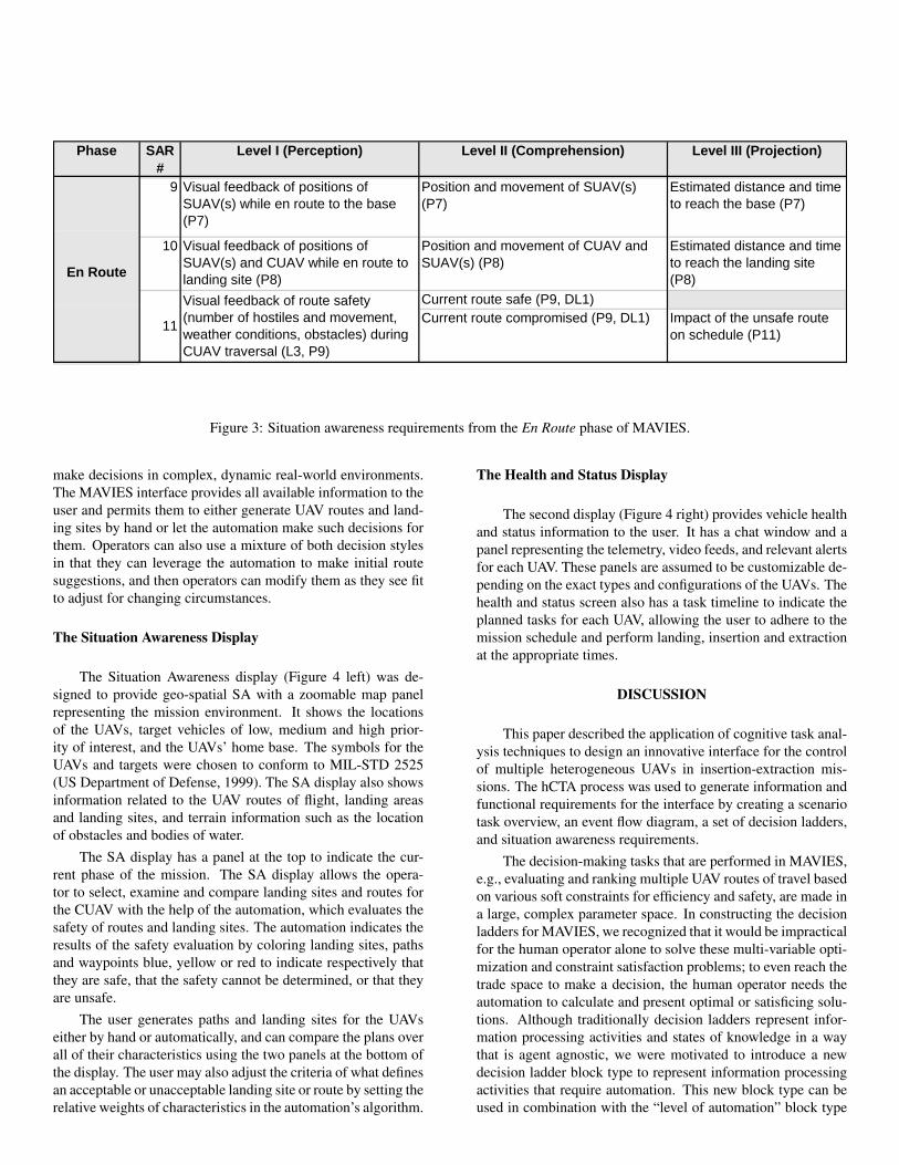
Three of the SARs are given as an example in Table 3.
These are from the En Route phase of MAVIES and representthe operator’s SA for the time and distance for the CUAV toreach the landing site, whether or not the CUAV needs escort(s),and the possibility that the route could be compromised by hos-tiles, weather, or discovered obstacles. Each component of SAis labeled to associate it with one or more blocks in the operatorevent flow structure. For example, P9 means that this require-ment is associated with Process 9 from the event flow and DL1means the requirement came from the first decision ladder.
The combined requirements from the situation awarenessand decision ladder analyses form the basis for information re-quirements for the actual display, detailed in the next section.
DISPLAY PROTOTYPE
The resulting MAVIES interface consists of two screens,a Situation Awareness display with major interface componentsfor supervising the vehicles, and a Health and Status display formonitoring the health of the vehicles and the status of the mis-sion (Figure 4). A prototype of the MAVIES user interface wasimplemented using the Qt cross-platform and application andUI framework (Nokia Corporation, 2012) in C++ on Windowsplatforms.
The interface is designed to accommodate both naturalis-tic and rational styles of decision making. Naturalistic deci-sion making (Klein, 2008) emphasizes modeling how humans
Phase SAR#
Level I (Perception) Level II (Comprehension) Level III (Projection)
9 Visual feedback of positions ofSUAV(s) while en route to the base(P7)
Position and movement of SUAV(s)(P7)
Estimated distance and timeto reach the base (P7)
10 Visual feedback of positions ofSUAV(s) and CUAV while en route tolanding site (P8)
Position and movement of CUAV andSUAV(s) (P8)
Estimated distance and timeto reach the landing site(P8)
Current route safe (P9, DL1)Current route compromised (P9, DL1) Impact of the unsafe route
on schedule (P11)
En Route
11
Visual feedback of route safety(number of hostiles and movement,weather conditions, obstacles) duringCUAV traversal (L3, P9)
Figure 3: Situation awareness requirements from the En Route phase of MAVIES.
make decisions in complex, dynamic real-world environments.The MAVIES interface provides all available information to theuser and permits them to either generate UAV routes and land-ing sites by hand or let the automation make such decisions forthem. Operators can also use a mixture of both decision stylesin that they can leverage the automation to make initial routesuggestions, and then operators can modify them as they see fitto adjust for changing circumstances.
The Situation Awareness Display
The Situation Awareness display (Figure 4 left) was de-signed to provide geo-spatial SA with a zoomable map panelrepresenting the mission environment. It shows the locationsof the UAVs, target vehicles of low, medium and high prior-ity of interest, and the UAVs’ home base. The symbols for theUAVs and targets were chosen to conform to MIL-STD 2525(US Department of Defense, 1999). The SA display also showsinformation related to the UAV routes of flight, landing areasand landing sites, and terrain information such as the locationof obstacles and bodies of water.
The SA display has a panel at the top to indicate the cur-rent phase of the mission. The SA display allows the opera-tor to select, examine and compare landing sites and routes forthe CUAV with the help of the automation, which evaluates thesafety of routes and landing sites. The automation indicates theresults of the safety evaluation by coloring landing sites, pathsand waypoints blue, yellow or red to indicate respectively thatthey are safe, that the safety cannot be determined, or that theyare unsafe.
The user generates paths and landing sites for the UAVseither by hand or automatically, and can compare the plans overall of their characteristics using the two panels at the bottom ofthe display. The user may also adjust the criteria of what definesan acceptable or unacceptable landing site or route by setting therelative weights of characteristics in the automation’s algorithm.
The Health and Status Display
The second display (Figure 4 right) provides vehicle healthand status information to the user. It has a chat window and apanel representing the telemetry, video feeds, and relevant alertsfor each UAV. These panels are assumed to be customizable de-pending on the exact types and configurations of the UAVs. Thehealth and status screen also has a task timeline to indicate theplanned tasks for each UAV, allowing the user to adhere to themission schedule and perform landing, insertion and extractionat the appropriate times.
DISCUSSION
This paper described the application of cognitive task anal-ysis techniques to design an innovative interface for the controlof multiple heterogeneous UAVs in insertion-extraction mis-sions. The hCTA process was used to generate information andfunctional requirements for the interface by creating a scenariotask overview, an event flow diagram, a set of decision ladders,and situation awareness requirements.
The decision-making tasks that are performed in MAVIES,e.g., evaluating and ranking multiple UAV routes of travel basedon various soft constraints for efficiency and safety, are made ina large, complex parameter space. In constructing the decisionladders for MAVIES, we recognized that it would be impracticalfor the human operator alone to solve these multi-variable opti-mization and constraint satisfaction problems; to even reach thetrade space to make a decision, the human operator needs theautomation to calculate and present optimal or satisficing solu-tions. Although traditionally decision ladders represent infor-mation processing activities and states of knowledge in a waythat is agent agnostic, we were motivated to introduce a newdecision ladder block type to represent information processingactivities that require automation. This new block type can beused in combination with the “level of automation” block type

RouteComparison
Settings
Map, VehiclesRoutes, and
Landing Sites
Landing SiteComparison
Settings
RouteComparison
Settings
Mission PhaseIndicator
Chat Window
Health, Status,Video and SensorFeeds from UAVs
MissionRelevantTimeline
Figure 4: MAVIES screen shots. Left: Situation Awareness display. Right: Health and Status display
that indicates where automation is optional but not required.The hCTA process is most useful when designing user in-
terfaces in a team environment. It communicates requirementsto the designers of algorithms and displays and provides trace-ability through multiple iterations of design, implementationand usability testing. This innovation enhances the decision lad-ders in their ability to convey that automation is required as anaid to humans when making decisions in a domain with difficultoptimization tasks.
As a result of the hCTA efforts and the resulting MAVIESdisplay, engineers are now working to design the algorithm tosupport this display. This Human Systems Engineering (HSE)approach is unusual, in that typically algorithm designers gen-erate the optimization algorithm first, and then the interface de-signers are left to support the operator with often incompleteinformation because the interface requirements of the humanwere not considered at the time of algorithm generation. Futurework will determine if this HSE approach is superior to a moretraditional SE approach that does not consider human require-ments early in the design process.
ACKNOWLEDGMENTS
The authors thank Manal Habib and Armen Mkrtchyan fortheir contributions to this paper.
REFERENCES
Endsley, M. (1995). Toward a theory of situation awareness indynamic systems. Human Factors, 37(1), 32–64.
Klein, G. (2008). Naturalistic decision making. Human Factors,50(3), 456–460.
Nehme, C., Scott, S., Cummings, M., & Furusho, C. (2006).Generating requirements for futuristic heterogeneous un-
manned systems. In Proceedings of the Human Factorsand Ergonomics Society (pp. 235–239). San Francisco,CA.
Nokia Corporation. (2012). Qt, a cross platform application andUI framework. Retrieved from http://qt.nokia.com/
Rasmussen, J. (1983). Skills, rules, and knowledge: signals,signs, and symbols, and other distinctions in human per-formance models. IEEE Transactions on Systems, Man,and Cybernetics, 13(3), 257–266.
Rasmussen, J., Pejtersen, A., & Goodstein, L. (1994). Cognitivesystems engineering. New York: John Wiley & Sons, Inc.
Scott, S., & Cummings, M. L. (2006). Cognitive task analysisfor the LCS operator (Tech. Report No. HAL2006-01).Cambridge, MA: MIT Humans and Automation Labora-tory.
Sheridan, T. B., & Verplank, W. (1978). Human and computercontrol of undersea teleoperators. Cambridge, MA: MITMan-Machine Systems Laboratory.
Tappan, J., Cummings, M. L., Mikkelsen, C., & Driediger, K.(2011). Mobile application for utility domains. In 13th In-ternational Conference on Human-Computer Interactionwith Mobile Devices and Services. Stockholm, Sweden.
Tappan, J., Pitman, D. J., Cummings, M. L., & Miglianico,D. (2011). Display requirements for an interactive railscheduling display. In HCI International Conference. Or-lando, FL, USA.
United States Army. (2010). Unmanned aircraft systemsroadmap, 2010-2035.
US Department of Defense. (1999). Interface standard, com-mon warfighting symbology (Tech. Report No. MIL-STD-2525B).