interactive grain image segmentation using graph cut …songwang/document/spie13.pdfinteractive...
TRANSCRIPT

Interactive Grain Image Segmentation using Graph Cut
Algorithms
Jarrell Waggonera, Youjie Zhoua, Je� Simmonsb, Ayman Salemb,
Marc De Graefc, and Song Wanga
aUniversity of South Carolina, Columbia, SC 29208, USA;bMaterials and Manufacturing Directorate, Air Force Research Labs, Dayton, OH 45433, USA;c Carnegie Mellon University, Department of Materials Science and Engineering, 5000 Forbes
Avenue, Pittsburgh, PA, 15213, USA
ABSTRACT
Segmenting materials images is a laborious and time-consuming process and automatic image segmentationalgorithms usually contain imperfections and errors. Interactive segmentation is a growing topic in the areas ofimage processing and computer vision, which seeks to �nd a balance between fully automatic methods and fully-manual segmentation processes. By allowing minimal and simplistic interaction from the user in an otherwiseautomatic algorithm, interactive segmentation is able to simultaneously reduce the time taken to segment animage while achieving better segmentation results. Given the specialized structure of materials images and levelof segmentation quality required, we show an interactive segmentation framework for materials images that hastwo key contributions: 1) a multi-labeling framework that can handle a large number of structures while stillquickly and conveniently allowing manual interaction in real-time, and 2) a parameter estimation approach thatprevents the user from having to manually specify parameters, increasing the simplicity of the interaction. Weshow a full formulation of each of these contributions and example results from their application.
Keywords: image segmentation, materials volume segmentation, segmentation propagation, interactive seg-mentation, graph-cut approaches
1. INTRODUCTION
Interactive segmentation is a rapidly-growing area of computer vision and has seen heightened interest recently.1,2
While traditional segmentation seeks to identify objects/structures within an image in a fully-automated fash-ion, interactive segmentation, similar to active learning,3 accomplishes the goal of image segmentation whileincorporating a sparse number of user interactions which are included as additional constraints or guidance inthe segmentation model or algorithm. These interactions may take on di�erent forms, and may include drawinga bounding box,4 roughly outlining a boundary,5 or drawing brush strokes inside and/or outside the objectof interest.6{9 A desired property of an interactive segmentation approach is that the user interaction be asconvenient (i.e., low cognitive load) and sparse (i.e., few in number) as possible, while simultaneously providingimmediate feedback to the user on every interaction.
Many existing methods segment the object of interest using a model learned from user interactions.4,7, 8
Other approaches incorporate interaction into morphological operations (watershed),2 co-segmentation,10 orincorporate machine-learning to aid in the interactive process.1,11 These interactive methods have been appliedto a number of domains, including natural images,4 medical images,12 and neuroimages.2,13
Further author information: (Send correspondence to J. Waggoner)J. Waggoner: E-mail: [email protected], Telephone: 847-261-4747Y. Zhou: E-mail: [email protected]. Simmons: E-mail: je�[email protected]. Salem: E-mail: [email protected]. De Graef: E-mail: [email protected]. Wang: E-mail: [email protected], Telephone: 803-777-2487

One domain that has been unaddressed in interactive segmentation literature is materials science imagesegmentation, where there are no existing techniques focusing solely on segmenting materials images using an in-teractive approach. Materials science is especially important to the development of new metals and biomaterials,and presents unique challenges in image segmentation. First, materials images often are 3D volumes14 made upof a sequence of individual 2D image \slices," as shown by the two sample slices in Figure 1. This large numberof slices must all be segmented to fully and properly analyze the 3D structure of the material. Second, dependingon the inter-slice distance, the 2D structure in two neighboring slices may show high continuity. Such inter-slicestructure continuity must be considered to achieve accurate segmentation. Third, materials volumes consist ofnumerous substructures (e.g.,\grains" in a metallic material, or \cells" in a biomaterial, etc.) with complex rela-tionships (e.g., adjacency/nonadjacency relationships) among them that determine many desirable properties ofthe material.15,16 Existing interactive segmentation techniques often only focus on foreground-background seg-mentation,4,8 and may not scale to the large number of substructures present in materials images. Other methodsmay handle multiple structures,2,13 but do not incorporate any prior knowledge about the unique relationshipsamong substructures in materials images.17,18 Finally, the imaging techniques used to obtain a materials imagevolume may result in signi�cant noise or other ambiguities that increases the di�culty to segment a materialsimage volume in a fully-automatic fashion.
There are a number of existing, non-interactive approaches to segment materials images.19,20 Among themost prominent is the work of Comer et al.21,22 on the EM/MPM algorithm, originating from.23 Other methodsthat have been speci�cally used on materials images include graph cut,24,25 stabilized inverse di�usion equa-tions,26 Bayesian methods,27,28 and the watershed29 method. Most often, materials images are opportunisticallysegmented by the simplest tools available, such as thresholding,30,31 or out-of-the-box methods such as water-shed or normalized cut. However, these methods do not incorporate any interaction for manual re�nement by auser. Some of these approaches may require signi�cant time to run; requiring the user to examine and correctproblems only after the algorithm is complete may not be practical if rapid re�nement is desired. Conversely, thegeneral-purpose interactive segmentation techniques discussed previously do not incorporate any speci�c domainknowledge about materials images, and thus may require additional e�ort on the part of the user than mayotherwise be needed when segmenting a materials image volume.
In this paper, we present an interactive segmentation approach to segment materials science image volumes.We show that an existing propagation-based materials image segmentation approach25 can be extended to allowfor convenient interactive segmentation. We illustrate the performance of the proposed approach by usingit to segment a materials image volume using smaller number of interactions compared with general-purposeinteractive segmentation methods that do not incorporate materials-speci�c priors. Finally, we develop methodsto estimate the parameters of this proposed approach to further reduce the number of user-required interactionsin the segmentation process.
The remainder of this paper is organized as follows: in Section 2 we discuss the proposed interactive segmen-tation approach for materials image volumes. In Section 3, we show how some of the parameters of the proposedmethod can be automatically estimated. In Section 4, we evaluate the proposed method's performance againstanother general-purpose interactive segmentation method. Finally, in Section 5 we provide brief concludingremarks.
2. INTERACTIVE MATERIALS IMAGE SEGMENTATION
In25 we developed a 3D materials science image segmentation method by propagating segmentation SU of a sliceU to a neighboring slice V , resulting in a segmentation SV . This way, using an initial segmentation on one slice,we can repeatedly propagate this segmentation to the remaining slices in the volume to obtain a complete 3Dsegmentation. This propagation was done while preserving the topology (i.e., non-adjacency relations among 2Dsegments), which led to a better performance when compared with methods that did not incorporate topologyas a prior. Speci�cally, let the segmentation
SU = fSU1 ; S
U2 ; : : : ; S
Un g;

S3V
S2V
S3U
S2U
S1VS1
U
SU SV
Propagation
S4VS4
U
Figure 1: Example of segmentation propagation, highlighting di�erent types of topology changes. Furtherdiscussion in the text.
where SUi ; i = 1 : : : n are disjoint segments in slice U , and this collection of segments makes up a partition of the
slice U ,
U =
n[i=1
SUi :
An example is shown in Figure 1 where all the segments (\grain" structures) are separated by red lines. Topropagate segmentation SU to a new slice V to yield the segmentation SV , we minimize the energy
E(SV ) =Xp2V
�p(SVi ) +
Xfp;qg2PV
n
�pq(SVi ; SV
j ) (1)
where PVn is the set of all 4-connected pixels. The unary term �p(S
Vi ), which represents a cost for a pixel p
being assigned to a segment SVi in slice V , was set to re ect the structure continuity between U and V ,
�p(SVi ) =
�0; distance(p; SU
i ) < d1; otherwise
(2)
where d is a dilation distance that re ects the maximum possible structural change between U and V .25 Inaddition, the binary term �pq(S
Vi ; SV
j ), which represents a cost for a pair of neighboring pixels p; q being assigned
to two (possibly the same) segments SVi ; SV
j , was constrained to preserve non-adjacency segment relationships
from U to V ; i.e., any two segments SVi ; SV
j are allowed to be adjacent (have pixels that are 4-connected between
them) if the corresponding segments in SUi ; S
Uj are also adjacent,
�pq(SVi ; SV
j ) =
8<:
0; i = j1; fSU
i ; SUj g =2 AU
g(p; q); fSUi ; S
Uj g 2 A
U
; (3)
where AU contains segment pairs that are adjacent in SU , and we set g(p; q) to re ect the image boundaryinformation in V .25 An example is shown in Figure 1, where SV
1 and SV2 are allowed to be adjacent because
SU1 and SU
2 are adjacent in SU . However, SV1 and SV
4 are not allowed to be adjacent (have an in�nity penalty)because SU
1 and SU4 are not adjacent in SU . This topology constraint was found to be particularly important

for materials images, and our proposed method was able to outperform other methods that did not incorporatesuch a prior.
While �nding the global minimum to this cost is NP-hard, this cost has been shown to be minimizable to alocal optimum using a graph-cut approach.32,33 However, one phenomenon that was observed in this previouswork was that, during propagation, 2D structure topology between U and V might not always be fully consistent.For example, a new 3D structure with no intersection in slice U might appear in slice V , e.g., the structure inthe yellow circle in Figure 1. Similarly, a 3D structure intersected by slice U might disappear in slice V , such asthe structure circled in magenta in Figure 1. This breaks the topology constraints given in Eq. (3) in some localregions. This may lead to spurious segments and missing structures, as circled in green and blue respectively, inFigure 1.
The previous method made use of a brute-force automated search to locate such spurious and missing struc-tures in V .25 However, particularly when the inter-slice distance is too large, it is not possible to examine everylocation for possible spurious or missing structures. In this paper, our goal is to develop e�ective interactivetools to allow a user to conveniently specify the local areas that contain spurious or missing structures, andincorporate such interactions to re�ne the segmentation SV to a corrected ~SV on slice V , using the same energyminimization algorithm. more speci�cally, we propose to allow the user to correct these two types of segmen-tation errors within this framework by: a) annotating the location of a new segment to handle cases where anew structure appears in slice V , and b) annotation of existing segments that should no longer be present insegmentation SV .
These interactions are inherently local because the 2D cross section of a 3D structure shows very small sizebefore appearing or disappearing from a neighboring 2D slice. Therefore, correcting SV to ~SV can be achievedby using the same energy minimization in local image areas around the interactive annotations. This is alsoimportant because interactive segmentation requires instantaneous user feedback. The previous propagationmethod segmented entire slices, which was more computationally intensive than is desirable in an interactivesystem. We will further discuss these two interactions, and how we identify local regions for each, in the followingsubsections.
2.1 Removal of Spurious Segments
For this interaction, we allow the user to select a spurious segment SVk for removal by clicking the mouse on this
segment in a visualized segmentation of SV . Instead of naively removing this segment by arbitrarily merging itinto one of its neighbors, we use the same energy minimization discussed above to assign the individual pixelsin SV
k to potentially di�erent neighboring segments. As discussed above, we identify a local region in which weupdate the segmentation. Speci�cally, this local region consists of the speci�ed SV
k and its neighboring segments,e.g., SV
1 ; SV2 ; SV
3 surrounding the spurious segment SVk in Figure 2 (a), and re-run the energy minimization within
this local region after modifying the � term to incorporate the interaction, resulting in an updated segmentationin this local region, as shown by the example in Figure 2 (b). For ease of notation, we use similar notation tothe adjacency de�nition in Eq. (3) by using fAV gk to refer to the set of segments neighboring the segment SV
k .This way, the local region for updating the segmentation is
L = fAV gk[
SVk : (4)
In this local region, we rerun the energy minimization of Eq. (1) by modifying the � term. In particular, wedo not allow any pixel to be assigned to SV
k since this segment is to be removed. Instead, the pixels initially inSVk can be assigned to any of the segments in fAV gk with 0 cost for the � term, i.e.,
8p 2 SVk ; �p( ~S
Vi ) =
�0; SV
i 2 fAV gk
1; otherwise
8p =2 SVk ; �p( ~S
Vi ) = �p(S
Vi )
(5)
By updating � in this fashion, we do not require the pixels previously in SVk merged into a single neighboring
segment. Instead, these pixels may be assigned to more than one segment in fAV gk, as shown in Figure 2 (b).
Note that this interaction is very simple and convenient, as it requires only a single click anywhere inside thespurious segment SV
k . The full algorithm for removing spurious segments is summarized in Algorithm 1.

SkV
S1V
S2V
S3V
(a) (b) (c)
Figure 2: Example selection of a spurious segment SVk for removal. (a) Chosen SV
k and surrounding segments.(b) Local region extracted around SV
k . (c) The updated segmentation in the extracted local region.
Algorithm 1 Interactively specifying segment to remove.
1: function RemoveSegment(SV ; SVk )
2: L fAV gkSSVk
3: 8p 2 L, build graph for energy minimization problem from25
4: � set from Eq. (5)5: ~SV SV incorporating the updated segmentation in L6: return updated ~SV
7: end function
2.2 Addition of Missing Segments
Unlike removal, interactively annotating an additional structure cannot be solely formulated as a simple modi-�cation of the � term in the energy minimization formulation. This is because the multi-labeling problem usedto optimize the energy minimization form in Eq. (1) optimizes over a �xed set of segments, and cannot intro-duce new segments. Thus, for each missing segment, we must explicitly create a new segment at the locationinteractively speci�ed by the user.
Based on the initial segmentation SV = fSV1 ; SV
2 ; : : : ; SVn g, we take as input from the user an annotation
specifying the center location c of the new segment ~SVn+1. In addition to this, we also accept two parameters from
the user: 1) the seed radius s specifying a circular region around c such that this circular region is completelycontained within the missing structure; 2) a dilation radius d, which is similar to the dilation parameter usedin,25 such that the circular region with this dilation radius d centered at c completely covers the missing structureto be segmented. We explicitly enforce that d � s for any choice of s. We call pixels within the seed radius sof c \seed pixels" and pixels within the dilation radius d of c \dilation pixels." In this interaction, seed pixelsare guaranteed to be part of the missing segment that is added, as shown by the green circle in Figure 3 (b),and dilation pixels, excluding seed pixels, are potentially part of the missing segment that is added, as shownby the blue area in Figure 3 (b). This makes the selection of s and d conceptually simple for the user to tune.In Section 3, we discuss how to automate the selection of s and d to further reduce the user's burden wheninteractively segmenting a materials volume.
Similar to the removal interaction in Section 2.1, we de�ne a local region around the speci�ed c to update thesegmentation of SV . Speci�cally, we de�ne this region by taking all segments in SV that contain one or moreseed or dilation pixels. In this local region we modify the � term of the energy minimization in Eq. (1) to obtainan updated segmentation. Speci�cally, we allow all seed and dilation pixels to be reassigned to the new segment~SVn+1 by setting
�p( ~SVn+1) =
�0; kp� ck � d1; otherwise
(6)

(a)
dsc
(b) (c)
Figure 3: Annotating the addition of a missing segment. (a) Segmentation SV with a missing segment nearthe center of the image. (b) Annotation of a center point c, along with a seed radius s and a dilation radius d,and the identi�ed local region for updating the segmentation. (c) The updated segmentation of the local regionshown in (b).
Algorithm 2 Interactively specifying segment to add.
1: function AddSegment(SV ; c, s, d)2: L union of all segments that contain a seed pixel or dilation pixel3: 8p 2 L, build graph for energy minimization problem from25
4: � set from Eq. (6) and Eq. (7)5: ~SV SV incorporating the updated segmentation in L6: return updated ~SV
7: end function
where k � k is the euclidean distance between pixels p and c. Furthermore, to insure that the seed pixels arealways guaranteed to be part of ~SV
n+1 we set an in�nity penalty for seed pixels assigned to any segment other
than ~SVn+1,
�p( ~SVi ) =
�1; kp� ck � s and i 6= n+ 1�p(S
Vi ); otherwise.
(7)
The full algorithm for adding a missing segment is summarized in Algorithm 2.
3. PARAMETER ESTIMATION
When interactively adding a new segment, as discussed in Section 2.2, the seed radius s and dilation radius d arerequired to be speci�ed by the user. This results in additional burden on the part of the user. In this section,we develop a parameter estimation approach to automatically select these two parameters so the user need onlyoverride them in very rare cases, or not at all.
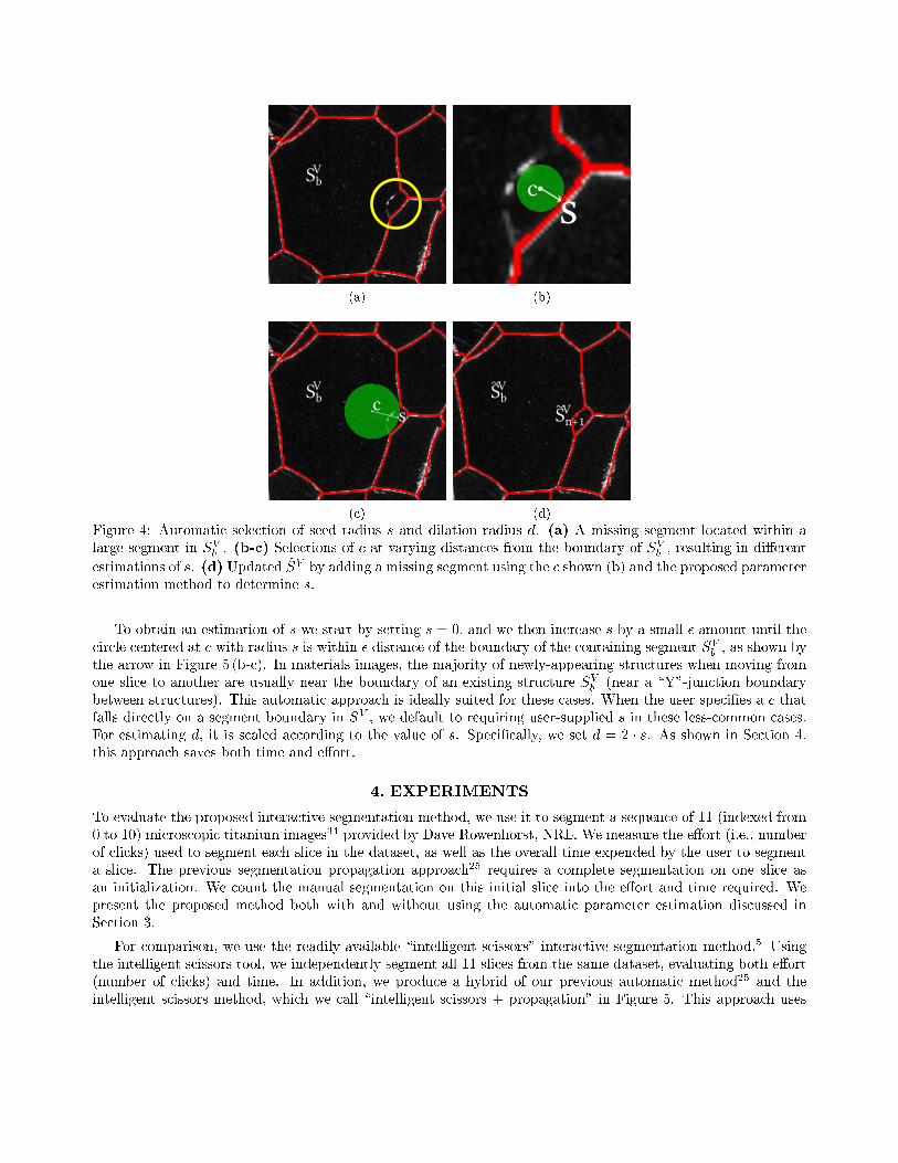
We do this by leveraging information about the center c the user provided relative to the initial segmentin which it resides. Generally a missing segment occurs when 2D cross-section intersects a new 3D structurein V . Given a small inter-slice distance, we expect that these missing segments are often small compared withits neighboring segments in slice V . An example is shown in Figure 4 (a), where a small segment is missing(indicated by the yellow circle) in the segmentation SV : this missing segment is mistakenly merged into a largeneighboring segment SV
b . Intuitively, placing c near the boundary of SVb likely indicates the missing segment is
small, as shown by Figure 4 (b). Conversely, placing c closer to the center of SVb likely indicates the resulting
missing segment is large as shown in Figure 4 (c). We make a simplifying assumption that we do not allow themissing segment to spill over the boundary of SV
b . For example, the selection of c and s in Figure 4 (b) is ableto generate the updated segmentation shown in Figure 4 (d).
cSbV
(a)
sc
(b)
SbV
c s
(c)
SbV
Sn+1V
~
~
(d)
Figure 4: Automatic selection of seed radius s and dilation radius d. (a) A missing segment located within alarge segment in SV
b . (b-c) Selections of c at varying distances from the boundary of SVb , resulting in di�erent
estimations of s. (d) Updated ~SV by adding a missing segment using the c shown (b) and the proposed parameterestimation method to determine s.
To obtain an estimation of s we start by setting s = 0, and we then increase s by a small � amount until thecircle centered at c with radius s is within � distance of the boundary of the containing segment SV
b , as shown bythe arrow in Figure 5 (b-c). In materials images, the majority of newly-appearing structures when moving fromone slice to another are usually near the boundary of an existing structure SV
b (near a \Y"-junction boundarybetween structures). This automatic approach is ideally suited for these cases. When the user speci�es a c thatfalls directly on a segment boundary in SV , we default to requiring user-supplied s in these less-common cases.For estimating d, it is scaled according to the value of s. Speci�cally, we set d = 2 � s. As shown in Section 4,this approach saves both time and e�ort.
4. EXPERIMENTS
To evaluate the proposed interactive segmentation method, we use it to segment a sequence of 11 (indexed from0 to 10) microscopic titanium images34 provided by Dave Rowenhorst, NRL. We measure the e�ort (i.e., numberof clicks) used to segment each slice in the dataset, as well as the overall time expended by the user to segmenta slice. The previous segmentation propagation approach25 requires a complete segmentation on one slice asan initialization. We count the manual segmentation on this initial slice into the e�ort and time required. Wepresent the proposed method both with and without using the automatic parameter estimation discussed inSection 3.
For comparison, we use the readily-available \intelligent scissors" interactive segmentation method.5 Usingthe intelligent scissors tool, we independently segment all 11 slices from the same dataset, evaluating both e�ort(number of clicks) and time. In addition, we produce a hybrid of our previous automatic method25 and theintelligent scissors method, which we call \intelligent scissors + propagation" in Figure 5. This approach uses

the method from25 to propagate a segmentation from an initial slice to the remaining slices, but it uses theintelligent scissors tool5 to carry out the interactive component instead of the interaction proposed in this paper.
The results of this comparative experiment are shown in Figure 5. Note that, in propagated methods (\Pro-posed," \Proposed + Parameter Estimation," and \Intelligent Scissors + Propagation"), the �rst slice is usedas the initial slice U , so it requires signi�cantly more e�ort and time to segment compared with the remainingslices. From Figure 5, we can see that the method proposed in this paper (\Proposed") allows much more rapid
0 2 4 6 8 10Slice
0
200
400
600
800
1000
Num
ber
of
Clic
ks
ProposedProposed + Parameter EstimationIntelligent ScissorsIntelligent Scissors + Propagation
(a) E�ort
0 2 4 6 8 10Slice
0
5
10
15
20
25
30
Tim
e (
Min
ute
s)
ProposedProposed + Parameter EstimationIntelligent ScissorsIntelligent Scissors + Propagation
(b) Time
Figure 5: Evaluation of (a) the amount of e�ort (number of clicks) and (b) time taken for a user to interactivelysegment the 11 sample slices. Smaller values are better, for both �gures.
segmentation time (< 5 minutes in most cases) and with much less e�ort (< 100 clicks in most cases) com-pared with the unpropagated intelligent scissors method. The intelligent scissors method (\Intelligent Scissors"),without the bene�t of propagation, requires signi�cantly more time and e�ort. The hybrid method (\IntelligentScissors + Propagation") fares better than the unpropagated intelligent scissors method, but it still requiresgreater e�ort than the proposed method. Finally, the proposed parameter estimation method (\Proposed +Parameter Estimation") can further reduce both the time and e�ort required by the proposed method.
In Figure 6, we show that the proposed interactive method is able to increase the segmentation accuracy ofour state-of-the-art materials image segmentation method in.25 As in our previous work,25 we use the precision,recall, and F-measure, which is the harmonic mean of the precision and recall,35 to show the segment boundarycoincidence with the manually-constructed ground truth segmentation. For both the proposed and previousautomatic methods, we propagate from an initial slice 0 to the remaining 10 slices, and the proposed interaction-enhanced method increases performance for all slices. Finally, qualitative segmentation results using the proposedinteractive method are shown in Figure 7 where we show the automatic segmentation results with spurious ormissing segments, the human annotation, and the updated segmentation.
5. CONCLUSION
We have presented an interactive segmentation method extended from our automatic segmentation propagationapproach. By allowing the user to interactively handle spurious and missing segments when propagating from oneslice to another, we show that the time required to segment a materials image volume, as well as the overall e�ort(number of clicks) needed for interaction, is much less than the comparison \intelligent scissors" method usedin popular image processing tools. By updating the segmentation within a local region around the interactiveannotation, we are able to obtain a fast, yet robust means to handle segmentation errors when a new structureappears or an existing structure disappears from the 2D cross-section of a particular slice in the volume. We alsointroduce a simple automatic technique to estimate the seed radius when adding a missing segment. We showthat this can further reduce the amount of time and e�ort needed by the proposed approach.

1 2 3 4 5 6 7 8 9 10Slice
0.960
0.965
0.970
0.975
0.980
0.985
0.990
0.995
1.000
F-m
easu
re
Proposed Interactive SegmentionPrevious Automatic Method
(a) F-measure
1 2 3 4 5 6 7 8 9 10Slice
0.970
0.975
0.980
0.985
0.990
0.995
1.000
Pre
cisi
on
Proposed Interactive SegmentionPrevious Automatic Method
(b) Precision
1 2 3 4 5 6 7 8 9 10Slice
0.95
0.96
0.97
0.98
0.99
1.00
Reca
ll
Proposed Interactive SegmentionPrevious Automatic Method
(c) Recall
Figure 6: Performance of the proposed interactive segmentation method compared with our previous automatedmethod25 measured by the boundary coincidence with the ground truth segmentation.
REFERENCES
[1] Kuang, Z., Schnieders, D., Zhou, H., Wong, K.-Y., Yu, Y., and Peng, B., \Learning image-speci�c param-eters for interactive segmentation," in [IEEE Conference on Computer Vision and Pattern Recognition ],590{597 (2012).
[2] Straehle, C., Koethe, U., Knott, G., Briggman, K., Denk, W., and Hamprecht, F., \Seeded watershed cutuncertainty estimators for guided interactive segmentation," in [IEEE Conference on Computer Vision andPattern Recognition ], 765{772 (2012).
[3] Settles, B., \Active learning literature survey," Computer Sciences Technical Report 1648, University ofWisconsin{Madison (2009).
[4] Rother, C., Kolmogorov, V., and Blake, A., \GrabCut: Interactive foreground extraction using iteratedgraph cuts," ACM Transactions on Graphics 23(3), 309{314 (2004).
[5] Mortensen, E. N. and Barrett, W. A., \Intelligent scissors for image composition," in [Proceedings of the22nd annual conference on Computer graphics and interactive techniques ], 191{198 (1995).
[6] Santner, J., Pock, T., and Bischof, H., \Interactive multi-label segmentation," in [IEEE Asian Conferenceon Computer Vision ], 397{410 (2011).
[7] Unger, M., Pock, T., Trobin, W., Cremers, D., and Bischof, H., \TVSeg|interactive total variation basedimage segmentation," in [British Machine Vision Conference 2008 ], 40.1{40.10 (2008).
[8] Boykov, Y. and Jolly, M., \Interactive graph cuts for optimal boundary & region segmentation of objectsin nd images," in [IEEE International Conference on Computer Vision ], 1, 105{112, IEEE (2001).

(a) (b)
(c) (d)
(e) (f)
(g) (h)
(i) (j)
Figure 7: Qualitative results where each sub�gure shows the initial automatic segmentation SV (left); the humanannotation (middle) with the seed pixels in green and dilation pixels in blue, and \X"s indicating spurioussegments to be removed; and the updated segmentation ~SV (right). Note that (f) and (g) illustrate removalannotation and the remaining illustrate addition annotation.
[9] Vezhnevets, V. and Konouchine, V., \Grow-Cut|interactive multi-label N-D image segmentation," in[Graphicon ], 150{156 (2005).
[10] Batra, D., Kowdle, A., Parikh, D., Luo, J., and Chen, T., \iCoseg: Interactive co-segmentation withintelligent scribble guidance," in [IEEE Conference on Computer Vision and Pattern Recognition ], 3169{3176 (2010).
[11] Top, A., Hamarneh, G., and Abugharbieh, R., \Active learning for interactive 3D image segmentation,"in [Proceedings of the 14th international conference on Medical image computing and computer-assistedintervention ], 603{610 (2011).
[12] Boykov, Y. and Jolly, M.-P., \Interactive organ segmentation using graph cuts," in [Medical Image Com-puting and Computer-Assisted Intervention ], 1935, 147{175 (2000).
[13] Straehle, C. N., K�othe, U., Knott, G., and Hamprecht, F. A., \Carving: scalable interactive segmenta-tion of neural volume electron microscopy images," in [Medical Image Computing and Computer-AssistedIntervention ], 653{660 (2011).
[14] Ibrahim, I. A., Mohamed, F. A., and Lavernia, E. J., \Particulate reinforced metal matrix composites|areview," Journal of Materials Science 26, 1137{1156 (1991).
[15] Swiler, T. P. and Holm, E. A., \Di�usion in polycrystalline microstructures," in [Annual Meeting of theAmerican Ceramic Society ], (1995).
[16] Rollett, A., Gottstein, G., Shvindlerman, L., and Molodov, D., \Grain boundary mobility: a brief review,"Z. Metallkunde 95, 226{229 (2004).
[17] Reed, R., [The Superalloys: Fundamentals and Applications ], Cambridge University Press (2006).
[18] Tan, J. and Saltzman, W., \Biomaterials with hierarchically de�ned micro- and nanoscale structure," Bio-materials 25(17), 3593{3601 (2004).
[19] Chuang, H., Hu�man, L., Comer, M., Simmons, J., and Pollak, I., \An automated segmentation for nickel-based superalloy," in [IEEE International Conference on Image Processing ], 2280{2283 (2008).
[20] Simmons, J. P., Chuang, P., Comer, M., Spowart, J. E., Uchic, M. D., and Graef, D. M., \Application andfurther development of advanced image processing algorithms for automated analysis of serial section imagedata," Modelling and Simulation in Materials Science and Engineering 17(2), 025002 (2009).
[21] Comer, M. and Delp, E., \Parameter estimation and segmentation of noisy or textured images using theEM algorithm and MPM estimation," in [IEEE International Conference on Image Processing ], 2, 650{654(1994).
[22] Comer, M. and Delp, E., \The EM/MPM algorithm for segmentation of textured images: Analysis andfurther experimental results," IEEE Transactions on Image Processing 9(10), 1731{1744 (2000).
[23] Marroquin, J., Mitter, S., and Poggio, T., \Probabilistic solution of ill-posed problems in computationalvision," Journal of the American Statistical Association , 76{89 (1987).
[24] Hu�man, L. M., Simmons, J. P., Graef, M. D., and Pollak, I., \Shape priors for map segmentation of alloymicrographs using graph cuts," in [IEEE Workshop on Statistical Signal Processing ], 28{30 (2011).
[25] Waggoner, J., Simmons, J., and Wang, S., \Combining global labeling and local relabeling for metallicimage segmentation," in [Proceedings of SPIE (Computational Imaging X) ], 8296 (2012).
[26] Hu�man, L., Simmons, J., and Pollak, I., \Segmentation of digital microscopy data for the analysis of defectstructures in materials using nonlinear di�usion," in [Proceedings of SPIE (Computational Imaging VI) ],(2008).
[27] Comer, M., Bouman, C., De Graef, M., and Simmons, J., \Bayesian methods for image segmentation,"JOM Journal of the Minerals, Metals and Materials Society 63, 55{57 (2011).
[28] Simmons, J., Bartha, B., De Graef, M., and Comer, M., \Development of bayesian segmentation techniquesfor automated segmentation of titanium alloy images," Microscopy and Microanalysis 14(S2), 602{603(2008).
[29] Li, Q., Ni, X., and Liu, G., \Ceramic image processing using the second curvelet transform and watershedalgorithm," in [IEEE International Conference on Robotics and Biomimetics ], 2037{2042 (2007).
[30] Gonzalez, R. C. and Woods, R. E., [Digital Image Processing (3rd Edition) ], Prentice Hall (2008).
[31] Shapiro, L. G. and Stockman, G. C., [Computer Vision ], Upper Saddle River, NJ: Prentice Hall (2001).

[32] Veksler, O., E�cient graph-based energy minimization methods in computer vision, PhD thesis, CornellUniversity, Ithaca, NY, USA (1999).
[33] Boykov, Y., Veksler, O., and Zabih, R., \Fast approximate energy minimization via graph cuts," IEEETransactions on Pattern Analysis and Machine Intelligence 23(11), 1222{1239 (2001).
[34] Rowenhorst, D., Lewis, A., and Spanos, G., \Three-dimensional analysis of grain topology and interfacecurvature in a �-titanium alloy," Acta Materialia 58, 5511{5519 (2010).
[35] Martin, D., Fowlkes, C., Tal, D., and Malik, J., \A database of human segmented natural images and its ap-plication to evaluating segmentation algorithms and measuring ecological statistics," in [IEEE InternationalConference on Computer Vision ], 2, 416{423 (2001).