intellikey · locking devices equipped with rim or mortise cylinders. questions regarding specific...
TRANSCRIPT

1 rev-073103
INTELLIKEYGENIUS AT YOUR FINGERTIPS
Installation Manual
R

2rev-073103

3 rev-073103
Contents
FCC Notice...................................................................................................................... 5Limited Warranty .............................................................................................................. 51.0 Introduction ................................................................................................................. 62.0 System components ................................................................................................... 63.0 Required installation skills and tools ........................................................................... 74.0 Door Preparation/Physical Installation ........................................................................ 85.0 Summary.................................................................................................................. 166.0 Maintenance ............................................................................................................ 16Specialty Lock Product Installations ................................................................................ 18Adams Rite type mortise Deadbolts ............................................................................... 19Lori Cylindrical Deadbolt ................................................................................................ 22Remote (Line) Power ..................................................................................................... 25Electronic Cylindrical Locksets ....................................................................................... 26INTELLIKEY Gate Lock installation ................................................................................. 30Typical DCU4000RBM Installations ................................................................................ 33DCU4000RBM .............................................................................................................. 34DCU4000RBM .............................................................................................................. 35LOCK ELECTRONICS MODULE .................................................................................. 36Typical remote power installation .................................................................................... 37Typical remote installation .............................................................................................. 38Typical electric strike installation ..................................................................................... 39Typical Magnetic Lock Installation ................................................................................... 40Remote Power Supply wiring......................................................................................... 41Glossary of Terms .......................................................................................................... 42Drawings List ................................................................................................................. 44Index .............................................................................................................................. 45Technical Support ........................................................................................................... 48

4rev-073103

5 rev-073103
FCC Notice
Warning: Changes or modifications to any unit not expressly approved by the party responsible for compliancecould void the user’s authority to operate the equipment.
Note: This equipment has been tested and found to comply with the limits for a class B digital device, pursuantto part 15 of the FCC Rules. These limits are designed to provide reasonable protection against harmfulinterference in a residential installation. This equipment generates, uses, and can radiate radio frequency energyand if not installed and used in accordance with the instructions, may cause harmful interference to radiocommunications. However, there is no guarantee that interference will not occur in a particular installation. Ifthis equipment does cause harmful interference to radio or television reception, which can be determined byturning the equipment off and on, the user is encouraged to try to correct the interference by one or more of thefollowing measures:
- Reorient or relocate the receiving antenna- Increase the separation between the equipment and receiver- Connect the equipment into an outlet on a circuit different from that to which the receiver is connected- Consult the dealer or an experienced radio TV technician for help
Limited Warranty
Intellikey Corp. warrants to the original purchaser that the products manufactured by it (the “Product”) to befree of defects in material and workmanship. Provided: (i) Intellikey has been notified within one year oforiginal installation or 18 months from date of purchase, has been properly registered with IntellikeyLtd. and have been given the opportunity of inspection by return of any alleged defective product to Intellikey,or its authorized distributor, at the address specified, free and clear of all liens and encumbrances, transportationprepaid, accompanied by an RMA stating the defects and proof of purchase; and (ii) The product has notbeen modified, abused, misused, or improperly installed, maintained and/or repaired during such period; and(iii) Such defect has not been caused by corrosion or ordinary wear and tear.
INTELLIKEY CORP. MAKES NO OTHER WARRANTY, AND ALL IMPLIED WARRANTIESINCLUDING ANY WARRANTY OF MERCHANTABILITY OR FITNESS FOR A PARTICULARPURPOSE ARE LIMITED TO THE DURATION OF THE EXPRESSED WARRANTY PERIOD ASSET FORTH ABOVE.INTELLIKEY CORPORATION’S MAXIMUM LIABILITY HEREUNDER ISLIMITED TO THE PURCHASE PRICE OF THE PRODUCT. IN NO EVENT SHALL THE COMPANYBE LIABLE FOR ANY CONSEQUENTIAL, INDIRECT, INCIDENTAL OR SPECIAL DAMAGESOF ANY NATURE ARISING FROM THE SALE OR USE OF THIS PRODUCT, WHETHER INCONTRACT, TORT, STRICT LIABILITY OR OTHERWISE.
Intellikey Corp. reserves the right to make changes in designs and specifications or to make additions orimprovements on its product line without notice and without incurring any obligation to incorporate them onproducts previously manufactured. The Intellikey Corp. is not responsible for any modification, addition, oralteration to our products by others.For warranty service and shipping instructions, contact Intellikey Corp. at:
INTELLIKEY Corporation4325 Woodland Park Drive, Suite 102
West Melbourne, FL 32904Phone 321-724-5595Fax: 321-724-5695
email: [email protected]
6rev-073103
1.0 Introduction
The INTELLIKEY Access Control System has been designed with ease of installation as a majorconsideration. It is estimated that it will typically take 30 minutes or less to install this system as aretrofit to an existing mortise lock on a wood door. You should allow additional time for metal doors,as well as, installations involving complex trim packages.
We strongly recommend before proceeding with the installation of the electronic lock and cylinderthat you familiarize yourself with this entire Lock Installation Guide. This will eliminate the need forcostly rework or repair due to inadequate understanding of the procedures required.
Because of the wide range of available door hardware and doors themselves, this guide can onlyprovide general guidelines for the installation. It is up to you, the professional installer, to insure thatthis system is installed correctly. For this reason, INTELLIKEY and its distributors cannot beresponsible for incorrect installations and any subsequent damages.
2.0 System components
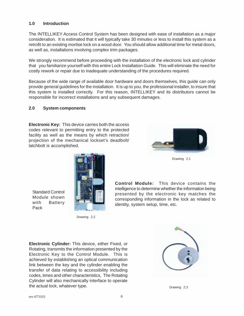
Electronic Key: This device carries both the accesscodes relevant to permitting entry to the protectedfacility as well as the means by which retraction/projection of the mechanical lockset’s deadbolt/latchbolt is accomplished.
Control Module: This device contains theintelligence to determine whether the information beingpresented by the electronic key matches thecorresponding information in the lock as related toidentity, system setup, time, etc.
Electronic Cylinder: This device, either Fixed, orRotating, transmits the information presented by theElectronic Key to the Control Module. This isachieved by establishing an optical communicationlink between the key and the cylinder enabling thetransfer of data relating to accessibility includingcodes, times and other characteristics, The RotatingCylinder will also mechanically interface to operatethe actual lock, whatever type.
Standard ControlModule shownwith BatteryPack
Drawing 2.1
Drawing 2.2
Drawing 2.3
7 rev-073103
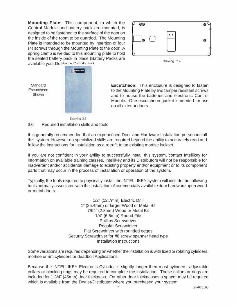
Mounting Plate: This component, to which theControl Module and battery pack are mounted, isdesigned to be fastened to the surface of the door onthe inside of the room to be guarded. The MountingPlate is intended to be mounted by insertion of four(4) screws through the Mounting Plate to the door. Aspring clamp is welded to this mounting plate to holdthe sealed battery pack in place (Battery Packs areavailable your Dealer or Distributor).
Escutcheon: This enclosure is designed to fastento the Mounting Plate by two tamper resistant screwsand to house the batteries and electronic ControlModule. One escutcheon gasket is needed for useon all exterior doors.
3.0 Required installation skills and tools
It is generally recommended that an experienced Door and Hardware installation person installthis system. However no specialized skills are required beyond the ability to accurately read andfollow the instructions for installation as a retrofit to an existing mortise lockset.
If you are not confident in your ability to successfully install this system, contact Intellikey forinformation on available training classes. Intellikey and its Distributors will not be responsible forinadvertent and/or accidental damage to existing property and/or equipment or to its componentparts that may occur in the process of installation or operation of the system.
Typically, the tools required to physically install the INTELLIKEY system will include the followingtools normally associated with the installation of commercially available door hardware upon woodor metal doors.
1/2” (12.7mm) Electric Drill1” (25.4mm) or larger Wood or Metal Bit
7/64” (2.8mm) Wood or Metal Bit1/4” (6.5mm) Round File
Phillips ScrewdriverRegular Screwdriver
Flat Screwdriver with rounded edgesSecurity Screwdriver for #8 screw spanner head type
Installation Instructions
Some variations are required depending on whether the installation is with fixed or rotating cylinders,mortise or rim cylinders or deadbolt Applications.
Because the INTELLIKEY Electronic Cylinder is slightly longer then most cylinders, adjustablecollars or blocking rings may be required to complete the installation. These collars or rings areincluded for 1 3/4” (45mm) door thickness. For other door thicknesses a spacer may be requiredwhich is available from the Dealer/Distributor where you purchased your system.
StandardEscutcheon
Shown
Drawing 2.4
Drawing 2.5

8rev-073103
4.0 Door Preparation/Physical Installation
The INTELLIKEY Electronic Access Control System is designed to retrofit to existing door hardwareoperated by rim or mortise cylinders. Consequently, only very minor modifications should be requiredto most existing installations, or only minor additional preparation is required for installations withnew door hardware.
Because the most meaningful variable in operating existing door hardware is the actuatingmechanism of the door hardware, the INTELLIKEY system is designed to function with most existinglocking devices equipped with rim or mortise cylinders.
Questions regarding specific applicability to existing door hardware should be referred toINTELLIKEY Corporation or INTELLIKEY’s approved dealer to determine suitability tospecialized circumstances.
4.1 Preparation for Installation
Prior to attempting installation of the INTELLIKEY Electronic Access Control System in your facility,please be sure to read and understand fully the instructions contained herein.
After opening the box containing the basic system components, please spread them out on anearby clean surface for easy identification. Caution should be exercised to prevent abuse of theControl Module and to prevent the abrasion or breaking of the connector cables. In addition, extracare should be made to insure that metal filings do not come into contact with the electronic board,Electronic Cylinder or any other electronic components as they may short out the electronics andcause permanent damage.
Normal installation time (excluding programming) is expected, on the average, to be less than thirty(30) minutes per door .
Standard Escutcheon
Electronic Cylinder
Control Module
Drawing 4.2
Drawing 4.1
Drawing 4.4
Drawing 4.3
Collar

9 rev-073103
4.2 Remove Existing Cylinder
Remove the existing mechanical rim or mortise cylinder by first removing the screws fastening thecylinder to the lock mechanism. (For mortise locksets, this will involve removal of the scalp platewhich permits access to the cylinder retaining screw. For rim cylinder applications, the door hardwareshould be removed to the extent that access to the cylinder retaining screws is obtained therebypermitting removal of the cylinder body itself.)
After the cylinder retaining screw is loosened, unscrew the cylinder from the lock body or in thecase of a rim cylinder just remove from door cavity. May require an existing key to help unscrewcylinder. In order to avoid wood or metal shavings entering the mortise lock, it is recommendedthat the mechanical lock be removed from the door before drilling the cable access hole.
Drawing 4.5Drawing 4.6
Face PlateScrew
Face PlateScrew
Cylinder SetScrews

10rev-073103
4.3 Drilling Cylinder Cable Access Hole
Having successfully accomplished the removal of the existing cylinder and the mechanical lock,the next step involves, as dictated by the existing or new door hardware, the drilling of a 1” (25.4mm)diameter hole through the surface of the door opposite to which the cylinder is to be installed.
Precise alignment of the hole allowing passage of the communication cable from the back of theElectronic Cylinder to the electronic Control Module is solely the responsibility of the installer.
Due consideration must be made for the type of trim that is to be employed with either the existingor new lockset. Extreme care must be taken that the location of the access hole is in such aposition that it will be covered either by the INTELLIKEY supplied Mounting Plate and Escutcheonor by the trim supplied by the door hardware manufacturer. This hole should be directly oppositethe hole in which the cylinder in installed. Consult INTELLIKEY Corporation or INTELLIKEY’s ApprovedDealer for special cover plates if needed.
1"
Inside
Inside
Inside
Drawing 4.7
Drawing 4.8
Drawing 4.9
Note: If door is fire ratedthe access hole must notexceed 1/2”.
Above shown with no trim.
11 rev-073103
4.4 Electronic Cylinder Installation
Having drilled the hole in the proper location, the next step is to install the Electronic Cylinder, eitherRim or Mortise, utilizing the appropriate fastenings for this purpose. Install the mechanical lockcaseback in the door.
Particular care must be paid to prevent the abrasion or twisting of the Communication Cableprojecting from the back of the Electronic Cylinder as it is installed in the door hardware. In bothinstances of the Rim or Mortise Cylinders, the installer must be absolutely sure the CommunicationCable does not become snarled, twisted, abraded or cut in any way.
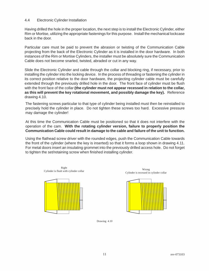
Slide the Electronic Cylinder and cable through the collar and blocking ring, if necessary, prior toinstalling the cylinder into the locking device. In the process of threading or fastening the cylinder inits correct position relative to the door hardware, the projecting cylinder cable must be carefullyextended through the previously drilled hole in the door. The front face of cylinder must be flushwith the front face of the collar (the cylinder must not appear recessed in relation to the collar,as this will prevent the key rotational movement, and possibly damage the key). Referencedrawing 4.10.
The fastening screws particular to that type of cylinder being installed must then be reinstalled toprecisely hold the cylinder in place. Do not tighten these screws too hard. Excessive pressuremay damage the cylinder!
At this time the Communication Cable must be positioned so that it does not interfere with theoperation of the cam. With the rotating cylinder version, failure to properly position theCommunication Cable could result in damage to the cable and failure of the unit to function.
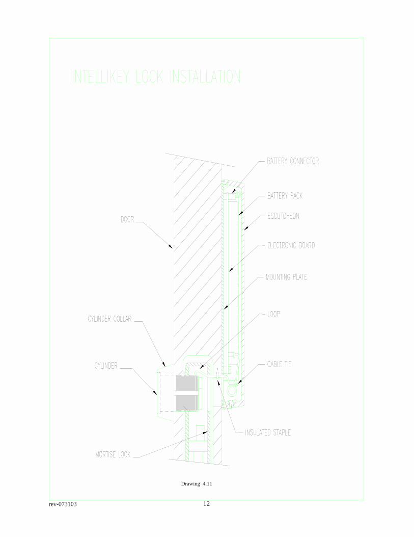
Using the flathead screw driver with the rounded edges, push the Communication Cable towardsthe front of the cylinder (where the key is inserted) so that it forms a loop shown in drawing 4.11.For metal doors insert an insulating grommet into the previously drilled access hole. Do not forgetto tighten the set/retaining screw when finished installing cylinder.
Drawing 4.10
RightCylinder is flush with cylinder collar Wrong
Cylinder is recessed in cylinder collar
12rev-073103
Drawing 4.11

13 rev-073103
4.5 Mounting Plate Installation
Depending on the type of installation required, the Control Module will usually be pre-installed on theMounting Plate. Although the Control Module is designed to be protected against many abusiveactions, care must be exercised in its handling.
SAFEGUARD AGAINST ELECTROSTATIC DISCHARGE, PHYSICAL ABUSE, AND USE WITHUNAUTHORIZED AUXILIARY DEVICES. USE OR ABUSE IN SUCH CIRCUMSTANCES IS EASILYDETECTABLE AND WILL VOID ANY WARRANTIES OTHERWISE CONTAINED HEREIN.
Doors with Sectional Trim
With the cylinder cable projecting from the surface of the door, position the Mounting Plate suchthat the cylinder cable will extend through the opening in the Mounting Plate. The hole which wasdrilled to permit passage of the connecting cable will be covered by the Mounting Plate andEscutcheon.
Doors with Escutcheon Trim
For doors equipped with Escutcheon trim, the procedure is slightly more complicated.
Holding the Mounting Plate against the surface of the door, align it in the desired position against theescutcheon trim. Allow an extra 1/4” (6.5mm) of clearance for the security cover (or better yet usetape or other temporary adhesive to hold the Mounting Plate so that the security cover can be fittedto check for the appropriate amount of clearance). Mark the location for drilling the pilot holes andusing the 7/64” (2.8mm) bit, drill the pilot holes in door where marked.
With the escutcheon trim and Mounting Plate aligned, also mark the point on the trim where thecylinder cable must pass through in order to align with the cable channel (Mounting Plate indentation)on the Mounting Plate.
Remove the inside escutcheon and drill a hole directly opposite that of the cylinder to allow passageof the communication cable.
In general, the escutcheon trim will require a small channel to be filed at the position marked inorder for the cylinder cable to pass through. Care must be taken to insure both proper alignmentwith the Mounting Plate channel and to avoid any pinching or cutting/abrasion of the CommunicationCable. Due to variations in escutcheon trim it is not possible to provide a definitive procedure for allapplications. For this reason, take extra care in planning and implementing the required modificationsto the door and associated trim. If required, cylinder extension cables are available from anINTELLIKEY Corporation dealer.
Place the cable from the cylinder through the hole filed in escutcheon trim and in the indentation onthe back of the Mounting Plate so that the Mounting Plate will be flat against the surface of the door.Fasten the Mounting Plate directly to the surface of the door with the screws as shown in drawing
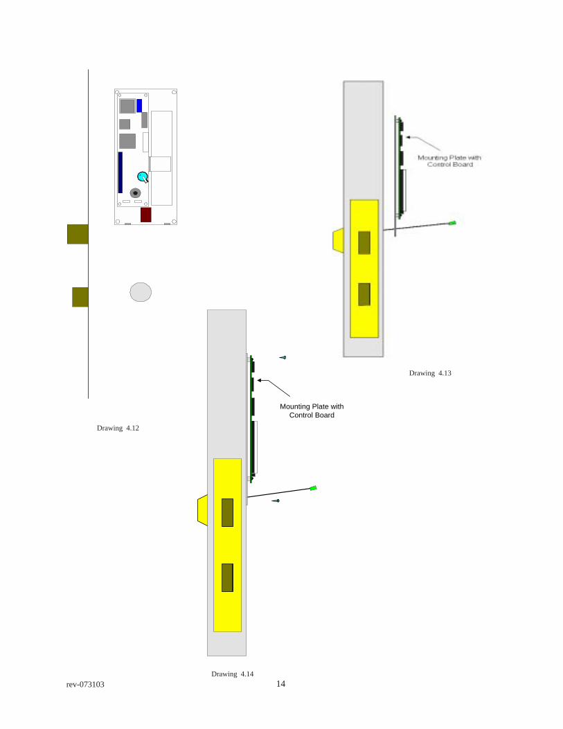
14rev-073103
+
Mounting Plate withControl Board
Drawing 4.12
Drawing 4.14
Drawing 4.13
15 rev-073103
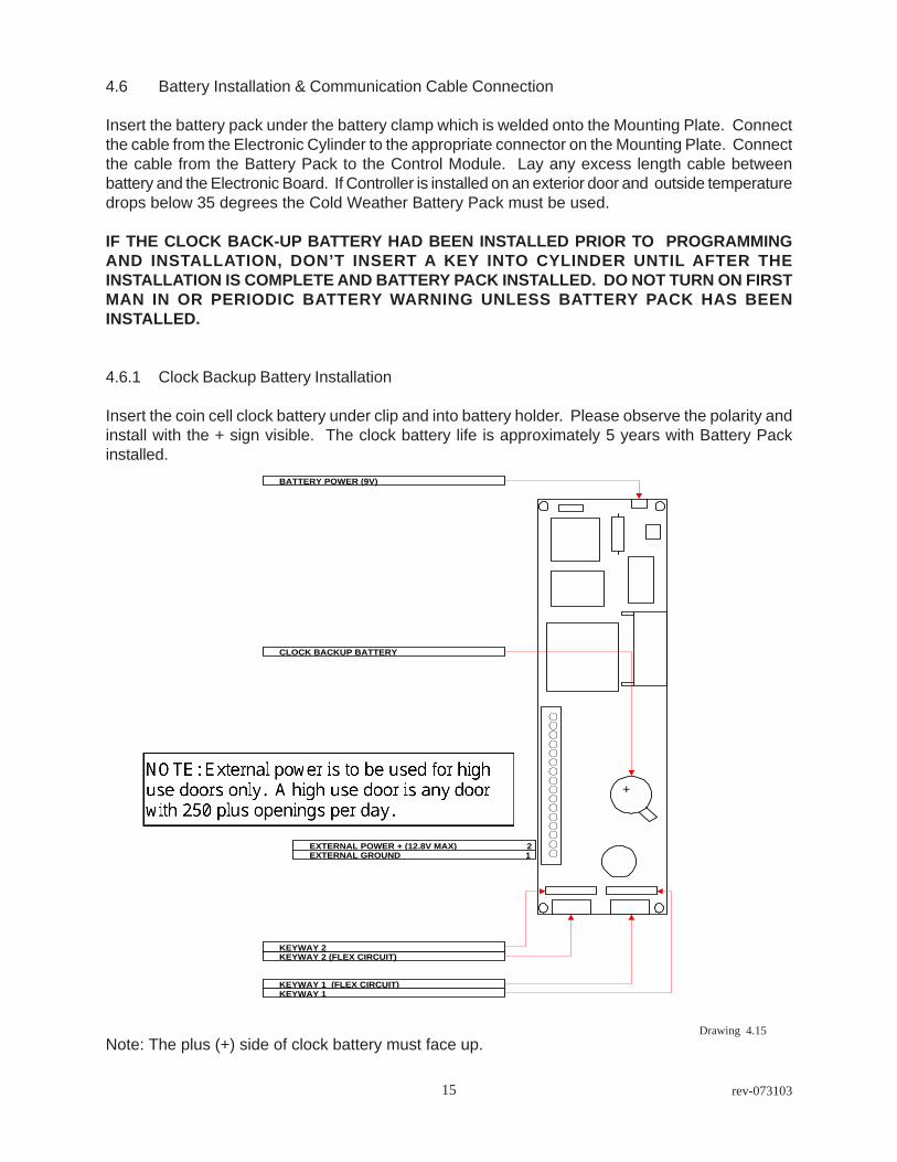
4.6 Battery Installation & Communication Cable Connection
Insert the battery pack under the battery clamp which is welded onto the Mounting Plate. Connectthe cable from the Electronic Cylinder to the appropriate connector on the Mounting Plate. Connectthe cable from the Battery Pack to the Control Module. Lay any excess length cable betweenbattery and the Electronic Board. If Controller is installed on an exterior door and outside temperaturedrops below 35 degrees the Cold Weather Battery Pack must be used.
IF THE CLOCK BACK-UP BATTERY HAD BEEN INSTALLED PRIOR TO PROGRAMMINGAND INSTALLATION, DON’T INSERT A KEY INTO CYLINDER UNTIL AFTER THEINSTALLATION IS COMPLETE AND BATTERY PACK INSTALLED. DO NOT TURN ON FIRSTMAN IN OR PERIODIC BATTERY WARNING UNLESS BATTERY PACK HAS BEENINSTALLED.
4.6.1 Clock Backup Battery Installation
Insert the coin cell clock battery under clip and into battery holder. Please observe the polarity andinstall with the + sign visible. The clock battery life is approximately 5 years with Battery Packinstalled.
Note: The plus (+) side of clock battery must face up.Drawing 4.15
EXTERNAL POWER + (12.8V MAX) 2EXTERNAL GROUND 1
KEYWAY 2 (FLEX CIRCUIT)KEYWAY 2
KEYWAY 1 (FLEX CIRCUIT)KEYWAY 1
BATTERY POWER (9V)
CLOCK BACKUP BATTERY
+

16rev-073103
4.7 Escutcheon Installation
Examination of the Mounting Plate and the Escutcheon will reveal an interlock mechanism at thetop of each piece which, when engaged by the other, act to prevent access to the Control Module.The lower end of the Escutcheon is fastened to the Mounting Plate by means to two (2) securityscrews which requires a special spanner driver #8 for installation.
Use of an Escutcheon Gasket for all installations is recommended as it will provide for a snug fit ofEscutcheon to door. THE ESCUTCHEON GASKET MUST BE INSTALLED IN ALL APPLICATIONSINVOLVING EXTERIOR AND/OR ANY INTERIOR DOORS EXPOSED TO MOISTURE.
4.7.1 Escutcheon Gasket Installation
Lay the Escutcheon on a flat surface with the inside facing up. Carefully remove only one end of thepaper backing from the gasket. Starting at the top or Logo end, of the Escutcheon lay gummedside of gasket on Escutcheon and press firmly down. Starting down one side of Escutcheon,remove paper backing and press on Escutcheon, being careful not to stretch gasket material.Install the other side the same as first and then finish across bottom.
5.0 Summary
This completes the physical installation of the INTELLIKEY Electronic Lock. If the Control Modulehad been previously programmed with the back up clock battery and Battery Pack installed, it isnow ready to operate. If the back up clock battery was not installed prior to programming, the timeand date will need to be set on the Control Module using a laptop computer and LPU or the RAK.
If the lock has not been programmed, you will need to program it prior to first use. “It is a goodidea to test the lock prior to closing the door” in order to prevent being placed in the awkwardposition of being locked out. If, as you are reading this, you find that you are locked out, you mayuse a laptop computer with appropriate site coded EZ123 and or Quantum Software and LPUInterface to unlock door.
In addition, the keys for your lock should have been programmed and ready for operation with thelock. Refer to the User’s Guide for information on how to program your Electronic Keys.
6.0 Maintenance
INTELLIKEY Lock Electronics need no maintenance. However the cylinder keyway should bemaintained as follows. Corrosion Block should be sprayed into all INTELLIKEY exterior cylinderkeyways every three months , with more than 100 transactions per day the cylinders should betreated once a month and interior cylinders every six months. Corrosion Block should be appliedinto the keyhole of the cylinder (one to two squirts) with particular attention being paid to the electricalcontact. Following application an INTELLIKEY Key should be inserted and the cylinder core rotatedseveral times so as to distribute the lubricant fully.
DO NOT USE GRAPHITE. Due to its conductive properties, graphite will cause shorts to thecylinder contacts.

17 rev-073103
Security Screws
Cylinder Flush with Collar
Drawing 5.1
Drawing 5.2

18rev-073103
Addendum A
Specialty Lock Product Installations
Adams Rite type deadbolts 18
Lori Cylindrical deabolts 21
Remote (Line) Power 24
Electronic Cylindrical locksets 25
Gate Locks 29

19 rev-073103
Drill acess hole3/8" to 3/4" Dia.
1 " to 1 1/2"
Drawing 6.13
Adams Rite type mortise Deadbolts
The Adams Rite mortise lock installation will require the use of a Slim Line lockcontroller and various thickness’ of adaptor/blocking rings.
The lockset should be removed from door to keep from getting metal chips in thelocking mechanism. On inside face of door measure up 1” to 1 1/2 ” from top ofcylinder/thumbturn hole and drill a 3/8” to 3/4” access hole. Refer to drawing 6.13.This access hole will be used to pull the cylinder cable out. Clean all metal chipsand burrs from cylinder cable access hole and cutout for lockset then reinstall thelockset in door. Next bend the cylinder cable flat against the cylinder cam and thenfrom center of cylinder bend up 90 degrees from cylinder, as per drawing 6.14. Apiece of tape may be used to temporarily hold cable against cam. Place the cylindersecurity collar and the correct thickness of blocking rings on cylinder.
Insert cylinder into exterior cylinder hole with communication cable extending throughlock and out of inside cylinder hole. Carefully turn cylinder into place being verycareful that the cylinder cable is not damaged or twisted. The cylinder cam shouldnot touch the cross bar of lockset. Insert a pull wire into inside cylinder hole throughlock and back out the access hole. Refer to drawing 6.15 for correct positioning ofpull wire. Attach cylinder cable to pull wire and VERY CAREFULLY work cylindercable back through lock and out the access hole. It is recommended that an insulatinggrommet be installed in the access hole. Using the flathead screw driver with roundededges, push the cable towards the front of the lock case. Refer to drawing 6.16 forcorrect position of cable. Make sure the piece of tape, if used, is removed at thistime.

20rev-073103
Drawing 6.14
Drawing 6.15

21 rev-073103
The Control Module will come pre-installed on the Mounting Plate. Although theControl Module is designed to be protected against many abusive actions, caremust be exercised in its handling.
Holding the Mounting Plate against the surface of the door, align it in its desiredposition. The hole which was drilled to permit passage of the connecting cablemust be covered by the Mounting Plate and Escutcheon. Mark the location fordrilling the pilot holes and using the 7/64” (2.8mm) bit, drill the pilot holes in the doorwhere marked. Place the cylinder cable through the Mounting Plate and fasten tothe surface of door with screws provided. The Mounting Plate with Control Modulemust be stored away when drilling pilot holes to avoid metal shavings getting incontact with electronics.
For installation of the battery, escutcheon and escutcheon gasket please refer topages 14 and 15 of the Installation Manual.
Drawing 6.16
22rev-073103
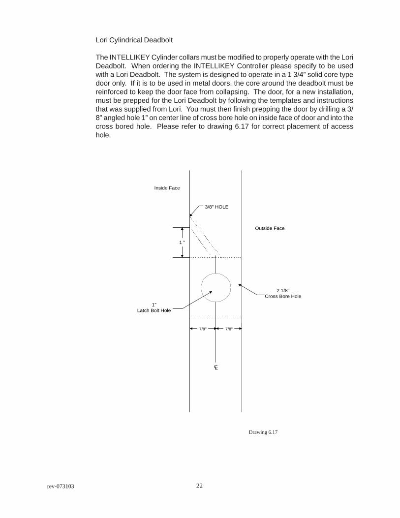
Lori Cylindrical Deadbolt
The INTELLIKEY Cylinder collars must be modified to properly operate with the LoriDeadbolt. When ordering the INTELLIKEY Controller please specify to be usedwith a Lori Deadbolt. The system is designed to operate in a 1 3/4” solid core typedoor only. If it is to be used in metal doors, the core around the deadbolt must bereinforced to keep the door face from collapsing. The door, for a new installation,must be prepped for the Lori Deadbolt by following the templates and instructionsthat was supplied from Lori. You must then finish prepping the door by drilling a 3/8” angled hole 1” on center line of cross bore hole on inside face of door and into thecross bored hole. Please refer to drawing 6.17 for correct placement of accesshole.
7/8"7/8"
3/8" HOLE
CL
2 1/8"Cross Bore Hole
1 "
Outside Face
Inside Face
1"Latch Bolt Hole
Drawing 6.17
23 rev-073103
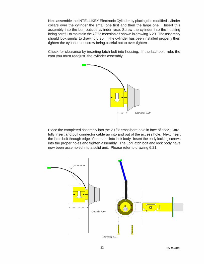
Place the completed assembly into the 2 1/8” cross bore hole in face of door. Care-fully insert and pull connector cable up into and out of the access hole. Next insertthe latch bolt through edge of door and into lock body. Insert the body locking screwsinto the proper holes and tighten assembly. The Lori latch bolt and lock body havenow been assembled into a solid unit. Please refer to drawing 6.21.
Drawing 6.20
Drawing 6.21
Next assemble the INTELLIKEY Electronic Cylinder by placing the modified cylindercollars over the cylinder the small one first and then the large one. Insert thisassembly into the Lori outside cylinder rose. Screw the cylinder into the housingbeing careful to maintain the 7/8” dimension as shown in drawing 6.20. The assemblyshould look similar to drawing 6.20. If the cylinder has been installed properly thentighten the cylinder set screw being careful not to over tighten.
Check for clearance by inserting latch bolt into housing. If the latchbolt rubs thecam you must readjust the cylinder assembly.
7/8"
7/8"7/8"
3/8" HOLE
Outside Face

24rev-073103
The Control Module will be pre-installed on the Mounting Plate. Although the ControlModule is designed to be protected against many abusive actions, care must beexercised in its handling.
Holding the Mounting Plate against the surface of the door, align it in the desiredposition. The hole which was drilled to permit passage of the connecting cableshould be covered by the Mounting Plate and Escutcheon. Mark the location fordrilling the pilot holes and using the 7/64” (2.8mm) bit, drill the pilot holes in the doorwhere marked. Place the cylinder through the Mounting Plate and fasten directly tothe surface of the door with the screws provided.
Before inserting a key, insert the battery pack under battery clamp, which is weldedon the Mounting Plate. Connect the communication cable from the ElectronicCylinder to the appropriate connector on the Control Module. Connect the cablefrom the Battery Pack to the Control Module. Lay any excess cable along the BatteryPack. Insert the coin cell clock battery under clip and into battery holder. Pleaseobserve the polarity and install with the + sign visible. Please reference section 4.6on page 14.
For the installation of the Escutcheon and Escutcheon Gasket please refer to section4.7 on page 15 of the Installation Manual.

25 rev-073103
Remote (Line) Power
For high use doors the ACS4000 with remote power supply with battery backupwould be the ideal choice. The equipment needed is a UL listed 9Vdc - 12Vdc,regulated ± .8 Vdc, power supply with battery backup. The minimum wire typewould be single pair 22 gauge stranded. If the distance between the power supplyand the INTELLIKEY Lock is 50 to 100 feet use of 18 gauge wire is required. Thecable is then run from the power supply to the Control Board and connected toscrew terminals 1 & 2 with terminal 1 being ground (-) and terminal 2 plus (+).
EXTERNAL POWER + (12.8V MAX) 2EXTERNAL GROUND 1
KEYWAY 2 (FLEX CIRCUIT)KEYWAY 2
KEYWAY 1 (FLEX CIRCUIT)KEYWAY 1
BATTERY POWER (9V)
CLOCK BACKUP BATTERY
+
Drawing 7.1

26rev-073103
Specialty Lock Installations
Electronic Cylindrical LocksetsThe installation instructions for the INTELLIKEY Cylindrical Lever Handle Lockset must befollowed. Failure to do so could result in damage to the lock and/or electronics and void thefactory warranty. The door preparation instructions and lock installation instructions arepackaged with each INTELLIKEY Lever Handle Lockset. CYLINDRICAL LOCKS ARE NOTRECOMMENED FOR EXTERIOR APPLICATIONS WHEN EXPOSED TO THE WEATHER.For applications below 320F. use of the Cold-Pack battery required.
Drawing 6.1 Drawing 6.2
Drawing 6.3 Drawing 6.4
Drawing 6.5
1. Mark horizontal line across edge of door.38” (965mm) is the usual height above floor.Fold template over edge of door, centering onhorizontal line. Mark centers of holes at properbackset.
2. Drill the following holes; A. 2 1/8” (54mm),B. 1” ( 25mm) in edge of door and cut out forlatch front 1 1/8” (29mm) wide x 2 1/4” (57mm)high x 5/32” (4mm) deep. C. Drill two (2) 5/16” (8mm) dia. holes through face of door. D.Drill 3/8” (10mm) hole at 450 angle upwardsthrough the door from the outside.

27 rev-073103
3. Install Latch unit
In Insert latch unit in door. (Besure bevel edge of bolt facesstrike plate.) Attach with twoscrews supplied.
4. Disassemble lockA. Loosen set screw and remove inside lever handle.B. Remove rose scalp.C. Remove 2 thru bolts.D. Remove rose assembly from lock.
Drawing 6.6
Drawing 6.7
28rev-073103
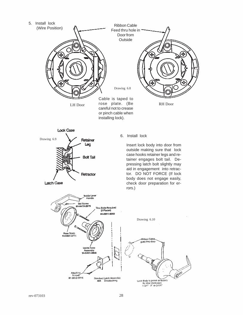
Ribbon CableFeed thru hole in
Door fromOutside
Cable is taped torose plate. (Becareful not to creaseor pinch cable wheninstalling lock).
LH Door RH Door
5. Install lock (Wire Position)
6. Install lock
Insert lock body into door fromoutside making sure that lockcase hooks retainer legs and re-tainer engages bolt tail. De-pressing latch bolt slightly mayaid in engagement into retrac-tor. DO NOT FORCE (If lockbody does not engage easily,check door preparation for er-rors.)
Drawing 6.8
Drawing 6.9
Drawing 6.10
29 rev-073103
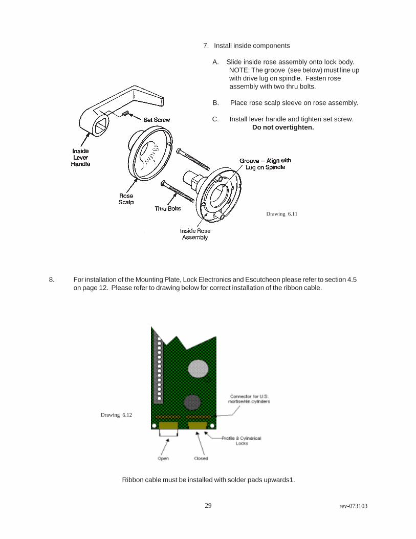
7. Install inside components
A. Slide inside rose assembly onto lock body. NOTE: The groove (see below) must line up with drive lug on spindle. Fasten rose assembly with two thru bolts.
B. Place rose scalp sleeve on rose assembly.
C. Install lever handle and tighten set screw.Do not overtighten.
Drawing 6.11
Drawing 6.12
8. For installation of the Mounting Plate, Lock Electronics and Escutcheon please refer to section 4.5on page 12. Please refer to drawing below for correct installation of the ribbon cable.
Ribbon cable must be installed with solder pads upwards1.

30rev-073103
INTELLIKEY Gate Lock installation
The INTELLIKEY Gate Lock is designed to retrofit mostswing or slide gates. The Gate Lock is fully compatiblewith INTELLIKEY’s ACS4000 access control system,allowing it to be added to an existing INTELLIKEYsystem. The lock mechanism is constructed ofhardened steel, automatically compensates for theusual misalignment inherent in swing gates and easyto install. All fasteners are made of stainless steel.
The equipment needed for the installation of the GateLock is a drill with 5/16” bit, #2 phillips, #1 phillips,adjustable wrench and an arc welder.
Prior to the installation you must check to see thatthere is a unobstructed clearance of no less than4” between the posts, and that the Gate Lock hasbeen programmed with the proper accessinformation.
Holding the Gate Lock with the controller housingon the secure side of the sliding or swinging part ofthe gate ( not the fixed side) and parallel to the gatefencing, mark the three (3) 1/4” bolt holes. Drillthese holes using a 5/16” bit. Loosely fasten theGate Lock with the bolts provided. Next tack weldthe chain hook to the post. Please refer to drawing8.2. Now remove the lock body screws and thecontroller. The chain hook should be tack weldedto the gate post.
4"
Drawing 8.1
With the controller removed, the chain hook canwelded to the gate post. Weld just the chainhook support bracket at the five (5) points.Please refer to drawing 8.3 and 8.4 for correctwelding locations.
Next reinstall the controller using the three (3)stainless steel lock body screws and the three(3) 1/4” stainless steel bolts with the screwheads on the secure side of gate. DO NOTTIGHTEN screws and bolts at this time. Testthe lock with a key. If the Gate Lock functionsproperly then tighten the three (3) lock bodyscrews and then the three 1/4” bolts. After thescrews and bolts are tight, tack weld the boltand nut being careful not to weld to the post.Please refer to drawing 8.5.
Mark & Drill using 5/16" bit
Tack weld chain hook to Postin this area both sides
Lockbody screws
Drawing 8.2Chain hook
Weld chain hookto Post
Drawing 8.3
Chain hook Chain hook
1
2
3
4
5
Drawing 8.4
Viewed from secure side

31 rev-073103
The INTELLIKEY Gate Lock is now installed. The last thing to be done is the installation of a loop ofchain or steel cable to the fixed side of the gate opening. When installing this loop allow enoughslack for misalignment in gate. For long term operation the Adams Rite lock supplied with theINTELLIKEY Gate Lock and the INTELLIKEY cylinders must be lubricated every 3 months usingCorrosion Block, INTELLIKEY part number 100795.
Lockbody screws
Drawing 8.4
Chain hook
Tack Weld
Drawing 8.5

32rev-073103
33 rev-073103
Addendum B
Typical DCU4000RBM Installations
DCU4000RBM wiring information with powered outputs 33
DCU4000RBM wiring information with dry contacts 34
Lock Electronics Module 35
Remote power installation 36
Remote controller installation 37
Electric strike installation 38
Magnetic lock installation 39
Remote power supply wiring 40
34rev-073103
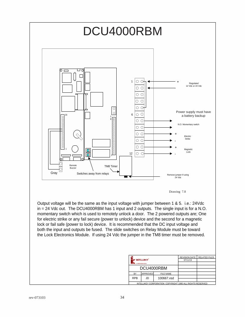
DCU4000RBM
Drawing 7.8
Power supply must havea battery backup
REVISION DATE RELATED FILES
BY APPROVED FILE NAME
INTELLIKEY CORPORATION COPYRIGHT 1995 ALL RIGHTS RESERVED
DCU4000RBM
100667.vsdRPB JD
97/11/19
Output voltage will be the same as the input voltage with jumper between 1 & 5. i.e.: 24Vdcin = 24 Vdc out. The DCU4000RBM has 1 input and 2 outputs. The single input is for a N.O.momentary switch which is used to remotely unlock a door. The 2 powered outputs are; Onefor electric strike or any fail secure (power to unlock) device and the second for a magneticlock or fail safe (power to lock) device. It is recommended that the DC input voltage andboth the input and outputs be fused. The slide switches on Relay Module must be towardthe Lock Electronics Module. If using 24 Vdc the jumper in the TM8 timer must be removed.
1
18
1
16
+
+
+
-
-
-Regulated
12 Vdc or 24 Vdc
ElectricStrike
MagneticLock
RemoteBuzzer
N.O. Momentary switch
1
6
12
Remove jumper if using24 Vdc
TM8 Timer
Gray Switches away from relays
35 rev-073103
DCU4000RBM
Drawing 7.8.1
REVISION DATE RELATED FILES
BY APPROVED FILE NAME
INTELLIKEY CORPORATION COPYRIGHT 1995 ALL RIGHTS RESERVED
1
18
1
16
+-
Regulated power supply withbattery backup
12 Vdc or 24 Vdc
RemoteBuzzer
N.O. Momentary switch
1
6
12
Remove jumper if using24 Vdc
TM8 Timer
Gray Switches away from relays
Common
Normallyopen contact
NormallyClosed contact
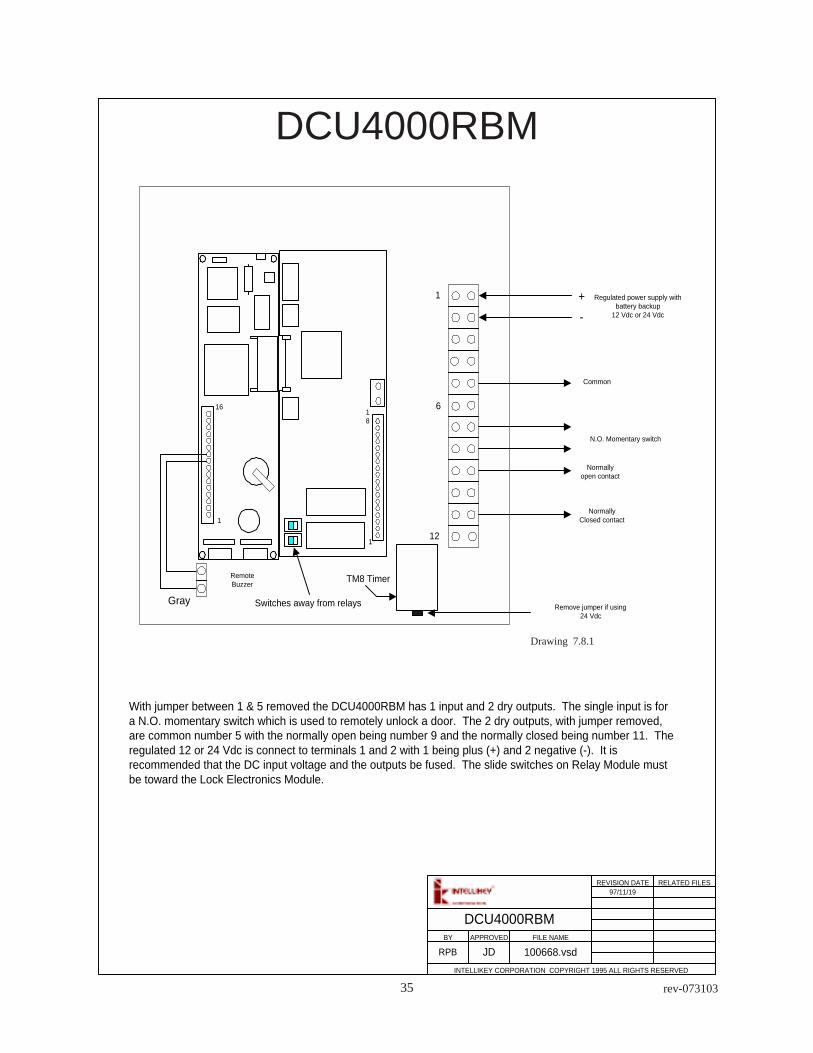
With jumper between 1 & 5 removed the DCU4000RBM has 1 input and 2 dry outputs. The single input is fora N.O. momentary switch which is used to remotely unlock a door. The 2 dry outputs, with jumper removed,are common number 5 with the normally open being number 9 and the normally closed being number 11. Theregulated 12 or 24 Vdc is connect to terminals 1 and 2 with 1 being plus (+) and 2 negative (-). It isrecommended that the DC input voltage and the outputs be fused. The slide switches on Relay Module mustbe toward the Lock Electronics Module.
DCU4000RBM
RPB JD 100668.vsd
97/11/19

36rev-073103
KEYWAY 2 (FLEX CIRCUIT)KEYWAY 2
KEYWAY 1 (FLEX CIRCUIT)KEYWAY 1
To external power supply12.8vdc maximum
1
32
456
910
8
12
7
13
1516
14
11
+-
REVISION DATE RELATED FILES
BY APPROVED FILE NAME
INTELLIKEY CORPORATION COPYRIGHT 1995 ALL RIGHTS RESERVED
95/08/2295/09/25
100629.vsdJDRPB
22 AWG
+
- Remote Buzzer
+
Clock Backup Battery
9 Vdc Battery Input
97/11/19Lock Electronics Module
Drawing 7.6
LOCK ELECTRONICSMODULE

37 rev-073103
A typical remote power installation with INTELLIKEY® Control Module and rotating Key Readermounted on door.
Typical remote power installation
Drawing 7.2
To 120 Vac
Use transfer hingeor door loop
Inside
REVISION DATE RELATED FILES
BY APPROVED FILE NAME
INTELLIKEY CORPORATION COPYRIGHT 1995 ALL RIGHTS RESERVED
Typical remote power
RPB 100669.vsd
97/06/18
Power Supply must be regulated9 to 12.8 Vdc Maximum with
Battery Backup
JD

38rev-073103
Typical remote installation
Typical remote installation using DCU and power supply. The extension cable running throughdoor and transfer loop to Door Control Unit (DCU). All INTELLIKEY electronics are mountedin the DCU. The regulated 12 Vdc power supply is connected to the DCU for continuousoperation. This type of installation would be for a high use door.
Drawing 7.3
REVISION DATE RELATED FILES
BY APPROVED FILE NAME
INTELLIKEY CORPORATION COPYRIGHT 1995 ALL RIGHTS RESERVED
DCU
Regulated 12 Vdc Power Supplywith Battery Backup
To 120 Vac
Door Loop
Typical Remote Installation
97/11/19
RPB JD 100670.vds

39 rev-073103
Operation is by means of the fixed Key Reader on exterior of door and connected to theDCU4000RBM. Output voltage of the DCU4000RBM is dependent on the input voltage frompower supply. The input voltage to DCU4000RBM can be 12 to 24 Vdc regulated. TheDCU4000RBM comes complete with one fixed Key Reader, mounting box, 12’ extension cableand DCU with Control Module/relay board. DCU4000RBM does not include a power supply,electric strike and/or wire. Use of a continuous duty electric strike is recommended. Note: DCinput voltage and output voltage should be fused.
Typical electric strike installationDCU4000RBM
Drawing 7.4
REVISION DATE RELATED FILES
BY APPROVED FILE NAME
INTELLIKEY CORPORATION COPYRIGHT 1995 ALL RIGHTS RESERVED
Regulated 12 Vdc Power Supplywith Battery Backup
To 120 Vac
Typical Electric Strike Installation
97/11/19
RPB JD 100671.vsd
DCU
Outside View

40rev-073103
REVISION DATE RELATED FILES
BY APPROVED FILE NAME
INTELLIKEY CORPORATION COPYRIGHT 1995 ALL RIGHTS RESERVED
Typical Magnetic Lock Installation
97/11/20
RPB JD 100672.vsd
DCU
Shown from inside
To 120 Vac
Regulated power supply withbattery backup
Key Readeroutside
Push buttonrelease inside
Typical Magnetic Lock InstallationDCU4000RBM
Drawing 7.5
Typical Magnetic lock installation with push button release and a fixed Key Reader installednear exterior entry of door. The DCU4000RBM houses all electronics and relays. Thepower supply is set to your required output voltage and is then cabled to the DCU4000RBM.120 Vac must be ran to the power supply. If required the power supply may be connectedto the fire alarm system. Please refer to page B1 for correct wiring diagrams.
41 rev-073103
KEYWAY 2 (FLEX CIRCUIT)KEYWAY 2
KEYWAY 1 (FLEX CIRCUIT)KEYWAY 1
To external power supply12.8vdc maximum
1
32
456
910
8
12
7
13
1516
14
11
+-
REVISION DATE RELATED FILES
BY APPROVED FILE NAME
INTELLIKEY CORPORATION COPYRIGHT 1995 ALL RIGHTS RESERVED
95/08/2295/09/25
100629.vsdJDRPB
22 AWG
+
- Remote Buzzer
+
Clock Backup Battery
9 Vdc Battery Input
97/11/19Lock Electronics Module
Remote PowerSupply wiring
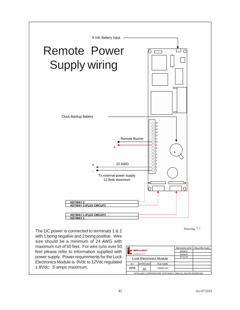
The DC power is connected to terminals 1 & 2with 1 being negative and 2 being positive. Wiresize should be a minimum of 24 AWG withmaximum run of 50 feet. For wire runs over 50feet please refer to information supplied withpower supply. Power requirements for the LockElectronics Module is 9Vdc to 12Vdc regulated±.8Vdc; .5 amps maximum.
Drawing 7.7
42rev-073103
Glossary of TermsBattery Pack
Control Module
CPU
Controller ProgrammingUnit
Cylinder Extension Cable
DCU4000
Door Control Unit
Electronic Cylinder
Electronic Key
Escutcheon
Escutcheon Gasket
EZ123 Software
KPU
Key Processing Unit
Key Programming Unit
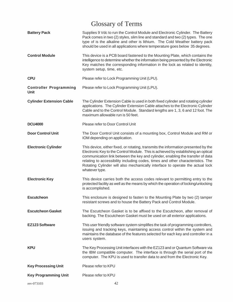
Supplies 9 Vdc to run the Control Module and Electronic Cylinder. The BatteryPack comes in two (2) styles, slim line and standard and two (2) types. The onetype of is the alkaline and other is lithium. The Cold Weather battery packshould be used in all applications where temperature goes below 35 degrees.
This device is a PCB board fastened to the Mounting Plate, which contains theintelligence to determine whether the information being presented by the ElectronicKey matches the corresponding information in the lock as related to identity,system setup, time, etc.
Please refer to Lock Programming Unit (LPU).
Please refer to Lock Programming Unit (LPU).
The Cylinder Extension Cable is used in both fixed cylinder and rotating cylinderapplications. The Cylinder Extension Cable attaches to the Electronic CylinderCable and to the Control Module. Standard lengths are 1, 3, 6 and 12 foot. Themaximum allowable run is 50 feet.
Please refer to Door Control Unit
The Door Control Unit consists of a mounting box, Control Module and RM orIOM depending on application.
This device, either fixed, or rotating, transmits the information presented by theElectronic Key to the Control Module. This is achieved by establishing an opticalcommunication link between the key and cylinder, enabling the transfer of datarelating to accessibility including codes, times and other characteristics. TheRotating Cylinder will also mechanically interface to operate the actual lockwhatever type.
This device carries both the access codes relevant to permitting entry to theprotected facility as well as the means by which the operation of locking/unlockingis accomplished.
This enclosure is designed to fasten to the Mounting Plate by two (2) tamperresistant screws and to house the Battery Pack and Control Module.
The Escutcheon Gasket is to be affixed to the Escutcheon, after removal ofbacking. The Escutcheon Gasket must be used on all exterior applications.
This user friendly software system simplifies the task of programming controllers,issuing and tracking keys, maintaining access control within the system andmaintains the database of the features selected for each key and controller in ausers system.
The Key Processing Unit interfaces with the EZ123 and or Quantum Software viathe IBM compatible computer. The interface is through the serial port of thecomputer. The KPU is used to transfer data to and from the Electronic Key.
Please refer to KPU
Please refer to KPU

43 rev-073103
Lock Electronics Module
Lock Programming Unit
LEM
Mounting Plate
Power Supply
Quantum Software
Remote Buzzer
Relay Module
RM
Please refer to Control Module
Lock Programming Unit (LPU) interfaces with the EZ123 and or Quantum Softwarevia an IBM compatible computer. The interface is through the serial port of thecomputer. The LPU is used to transfer data to and from the Control Module.
Please refer to Control Module
This component, to which the Control Module and Battery Pack is mounted, isdesigned to be fastened to the surface of the door on the inside of the room to beprotected. The Mounting Plate is intended to be mounted by four (4) screwsthrough the plate to the door. A spring clamp is welded to this Mounting Plate tohold the sealed Battery Pack in place.
The Power Supply is used to supply the correct regulated voltage to a ControlModule or DCU4000 unit. The PS1 power supply is capable of controlling one(1) DCU4000RBM or DCU4000IOM. The maximum recommended wire run is 50feet with a wire size of 22 AWG. For longer runs please refer to the power supplyinstruction manual.
This user friendly software system simplifies the task of programming controllers,issuing and tracking keys, maintaining access control within the system andmaintains the database of the features selected for each key and controller in ausers system.
The remote buzzer can be used when the audible indications can not bedistinguished at the Electronic Cylinder. The maximum distance from ControlModule is 36 feet.
The Relay Module attaches to the 4000 series Control Module by means of aconnector. The Relay Module allows input of 12.8 to 35 Vdc (13.8 isrecommended). The Relay Module contains up to two (2) relays, K2, is controlledby the Control Module and one relay, K1, is controlled by an external source.
Please refer to Relay Module.

44rev-073103
Drawings List
Drawing Number Description Page Number
2.1 Electronic Key 052.2 Control Module 052.3 Electronic Cylinder 052.4 Mounting Plate 062.5 Escutcheon 064.1 Cylinder Collar 074.2 Standard Escutcheon 074.3 Electronic Cylinder 074.4 Mounting Plate, Electronics & Battery 074.5 Outside Front Mortise Lock 084.6 Outside Front Mortise Lock 084.7 Communication Cable access hole 094.8 Installing Electronic Cylinder 094.9 Electronic Cylinder Installed 094.10 Proper cylinder depth in collar 104.11 INTELLIKEY installation 114.12 - 4.14 Installing Mounting Plate 134.15 Lock Electronics Module 145.1, 5.2 Installing gasket & escutcheon 166.1 - 6.5 marking & prepping cylindrical lockset 256.6 installing latch bolt 266.7 disassembling lock 266.8 cable position cylindrical lockset 276.9, 6.10 installing cylindrical lockset 276.11 assembly of inside handle 286.12 connecting ribbon cable to LEM 286.13 communication cable hole Adams Rite 186.14, 6.15 installing Electronic Cylinder in Adams Rite 196.16 installing Electronic Cylinder in Adams Rite 206.17 prepping door for Lori deadbolt 216.20 - 6.21 installing Lori deadbolt 227.1 LEM 247.2 remote power installation 367.3 typical remote installation 377.4 electric strike installation 387.5 magnetic lock installation 397.6 LEM 357.7 LEM with remote buzzer 407.8 DCU4000RBM powered outputs 337.8.1 DCURBM with dry contacts 347.9 DCU4000-IOM 427.10 DCU4000-IOM wiring 438.1 -8.4 INTELLIKEY Gate Lock 298.5 INTELLIKEY Gate Lock 30

45 rev-073103
IndexA
Access Hole 9, 18, 22ACS4000 24Adams Rite 18
B
Backup Battery 14Battery Pack 6, 14, 23, 44Belden 85102 43Blocking ring 18
C
Cable 43Chain hook 29Clock battery 14, 15, 23Coin cell 23Cold Weather Battery Pack 14Collar 6, 7, 10Communication Cable 9, 10, 12, 14, 18, 23, 37, 46Control Module 5, 6, 7, 9, 12, 14, 15, 20, 23, 28, 36, 38, 44, 46Controller Programming Unit 44Corrosion Block 30CPU 15, 44CR1220 14, 23Cylinder collar 22Cylinder Extension Cable 44Cylindrical Lockset 25
D
DCU 37, 38DCU4000 44DCU4000-IOM 42DCU4000RBM 33, 34, 38, 39, 46Door Control Unit 37, 38, 44
E
Electric strike 38Electric strike installation 38Electronic Cylinder 5, 6, 7, 9, 10, 14, 22, 23, 44, 46Electronic Cylindrical Lockset 25Electronic Key 5, 15, 44, 46Electronic lock 5Escutcheon 6, 7, 9, 12, 15, 20, 23, 28, 44, 46Escutcheon Gasket 15, 20, 23, 44Escutcheon Trim 12Extension cable 37
F
FCC Notice 4

46rev-073103
Fixed Key Reader 38, 39
G
Gasket Installation 15Gate Lock 29, 30
I
Installation skills 6IntelliNet 42, 43
K
Key Reader 38
L
Latch bolt 22, 27Latch unit 26LEM 44Lever handle 25, 26Limited Warranty 4Lock Electronics 28Lock Electronics Module 44Lori 21, 22
M
Magnetic lock 39Magnetic Lock Installation 39Mounting Plate 6, 9, 12, 14, 15, 20, 23, 28, 44, 46
N
NSI card 42
O
On Line 42
P
Pathfinder 45Physical Installation 7Power supply 24, 37, 38, 45
Q
Quantum Software 15, 42, 45
R
RAK 15Relay Module 45Remote Power Supply 40Remote Buzzer 45Remote power 36Remote power installation 36Ribbon Cable 27RM 45Rose assembly 26, 28Rose scalp 26, 28

47 rev-073103
Rotating Cylinder 5
S
Sectional Trim 12Security collar 18Specialty Lock 25System components 5
T
Tools 6Transfer loop 37
W
Warranty 4

48rev-073103
100596 - GID
Technical Support
For technical support for your INTELLIKEY products, contact your local INTELLIKEY dealer,or contact INTELLIKEY directly:
INTELLIKEY Corporation4325 Woodland Park drive
Suite 102West Melbourne, FL 32904
Phone: 321-724-5595Fax: 321-724-5695
email: [email protected]@intellikey.comwww.intellikey.com
These materials are protected under US copyright laws. All contents current at time of publication.INTELLIKEY reserves the right to change availability of any item in this manual, its design, construction,and/or its materials.
The INTELLIKEY logo is a registered trademark of INTELLIKEY Corporation. INTELLIKEY,Quantum, EZ123, System 1000 and System 4000 are trademarks of INTELLIKEY Corporation. Otherproduct brand names may be trademarks or registered trademarks of their respective owners and arementioned for reference purposes only.
Psion is a registered trademark of Psion Corporation.
The contents of this manual Copyrighted 1998,1999, 2000, 2002, 2003 by INTELLIKEY Corporation.

49 rev-073103

50rev-073103