intelligent workgroup switch installation guide · pdf fileon the tri-pole power plug to a...
TRANSCRIPT

Intelligent Workgroup Switch
Installation Guide


Installation Guide
Intelligent Workgroup Switchwith 24 10BASE-T / 100BASE-TX (RJ-45) Ports, and 2 Slots for 100BASE-FX or Gigabit Uplink Modules

SF-2024FE012004-R01150xxxxxxxxxxx

Compliances and Safety Warnings
FCC - Class AThis equipment generates, uses, and can radiate radio frequency energy and, if not installed and used in accordance with the instruction manual, may cause interference to radio communications. It has been tested and found to comply with the limits for a Class A computing device pursuant to Subpart B of Part 15 of FCC Rules, which are designed to provide reasonable protection against such interference when operated in a commercial environment. Operation of this equipment in a residential area is likely to cause interference, in which case the user, at his own expense, will be required to take whatever measures may be required to correct the interference. You are cautioned that changes or modifications not expressly approved by the party responsible for compliance could void your authority to operate the equipment.
You may use unshielded twisted-pair (UTP) for RJ-45 connections - Category 3 or better for 10 Mbps connections, Category 5 or better for 100 Mbps connections, Category 5, 5e, or 6 for 1000 Mbps connections. For fiber optic connections, you may use 50/125 or 62.5/125 micron multimode fiber or 9/125 micron single-mode fiber.
Warnings: 1. Wear an anti-static wrist strap or take other suitable measures to prevent electrostatic discharge when handling this equipment.
2. When connecting this hub to a power outlet, connect the field ground lead on the tri-pole power plug to a valid earth ground line to prevent electrical hazards.
Industry Canada - Class AThis digital apparatus does not exceed the Class A limits for radio noise emissions from digital apparatus as set out in the interference-causing equipment standard entitled “Digital Apparatus,” ICES-003 of the Department of Communications.
Cet appareil numérique respecte les limites de bruits radioélectriques applicables aux appareils numériques de Classe A prescrites dans la norme sur le matériel brouilleur: “Appareils Numériques,” NMB-003 édictée par le ministère des Communications.
Japan VCCI Class A
i

CE Mark Declaration of Conformance for EMI and Safety (EEC)This information technology equipment complies with the requirements of the Council Directive 89/336/EEC on the Approximation of the laws of the Member States relating to Electromagnetic Compatibility and 73/23/EEC for electrical equipment used within certain voltage limits and the Amendment Directive 93/68/EEC. For the evaluation of the compliance with these Directives, the following standards were applied:
Warning! Do not plug a phone jack connector in the RJ-45 port. This may damage this device. Les raccordeurs ne sont pas utilisé pour le système téléphonique!
Australia AS/NZS 3548 (1995) - Class A
RFI Emission: • Limit class A according to EN 55022:1998
• Limit class A for harmonic current emission according to EN 61000-3-2/1995
• Limitation of voltage fluctuation and flicker in low-voltage supply system according to EN 61000-3-3/1995
Immunity: • Product family standard according to EN 55024:1998
• Electrostatic Discharge according to EN 61000-4-2:1995 (Contact Discharge: ±4 kV, Air Discharge: ±8 kV)
• Radio-frequency electromagnetic field according to EN 61000-4-3:1996 (80 - 1000 MHz with 1 kHz AM 80% Modulation: 3 V/m)
• Electrical fast transient/burst according to EN 61000-4-4:1995 (AC/DC power supply: ±1 kV, Data/Signal lines: ±0.5 kV)
• Surge immunity test according to EN 61000-4-5:1995 (AC/DC Line to Line: ±1 kV, AC/DC Line to Earth: ±2 kV)
• Immunity to conducted disturbances, Induced by radio-frequency fields: EN 61000-4-6:1996 (0.15 - 80 MHz with 1 kHz AM 80% Modulation: 3 V/m)
• Power frequency magnetic field immunity test according to EN 61000-4-8:1993 (1 A/m at frequency 50 Hz)
• Voltage dips, short interruptions and voltage variations immunity test according to EN 61000-4-11:1994 (>95% Reduction @10 ms, 30% Reduction @500 ms, >95% Reduction @5000 ms)
LVD: • EN 60950 (A1/1992; A2/1993; A3/1993; A4/1995; A11/1997)
ACN 066 352 010
ii

Safety Compliance
Warning: Fiber Optic Port Safety
Avertissment: Ports pour fibres optiques - sécurité sur le plan optique
Warnhinweis: Faseroptikanschlüsse - Optische Sicherheit
Underwriters Laboratories Compliance StatementImportant! Before making connections, make sure you have the correct cord set. Check it (read the label on the cable) against the following:
The unit automatically matches the connected input voltage. Therefore, no additional adjustments are necessary when connecting it to any input voltage within the range marked on the rear panel.
When using a fiber optic port, never look at the transmit laser while it is powered on. Also, never look directly at the fiber TX port and fiber cable ends when they are powered on.
Ne regardez jamais le laser tant qu'il est sous tension. Ne regardez jamais directement le port TX (Transmission) à fibres optiques et les embouts de câbles à fibres optiques tant qu'ils sont sous tension.
Niemals ein Übertragungslaser betrachten, während dieses eingeschaltet ist. Niemals direkt auf den Faser-TX-Anschluß und auf die Faserkabelenden schauen, während diese eingeschaltet sind.
Operating Voltage Electrical Cord Requirements
Operating Voltage Cord Set Specifications
120 Volts UL Listed/CSA Certified Cord Set
Minimum 18 AWG
Type SVT or SJT three conductor cord
Maximum length of 15 feet
Parallel blade, grounding type attachment plug rated 15A, 125V
240 Volts (Europe only) Cord Set with H05VV-F cord having three conductors with minimum diameter of 0.75 mm2
IEC-320 receptacle
Male plug rated 10A, 250V
CLASS I
LASER DEVICE
DISPOSITIF LASER
DE CLASSE I
LASERGER
DER KLASSE I
ÄT
iii

Wichtige Sicherheitshinweise (Germany)
1. Bitte lesen Sie diese Hinweise sorgfältig durch.2. Heben Sie diese Anleitung für den späteren Gebrauch auf.3. Vor jedem Reinigen ist das Gerät vom Stromnetz zu trennen. Verwenden Sie keine
Flüssigoder Aerosolreiniger. Am besten eignet sich ein angefeuchtetes Tuch zur Reinigung.
4. Die Netzanschlu ßsteckdose soll nahe dem Gerät angebracht und leicht zugänglich sein.5. Das Gerät ist vor Feuchtigkeit zu schützen.6. Bei der Aufstellung des Gerätes ist auf sicheren Stand zu achten. Ein Kippen oder Fallen
könnte Beschädigungen hervorrufen.7. Die Belüftungsöffnungen dienen der Luftzirkulation, die das Gerät vor Überhitzung schützt.
Sorgen Sie dafür, daß diese Öffnungen nicht abgedeckt werden.8. Beachten Sie beim Anschluß an das Stromnetz die Anschlußwerte.9. Verlegen Sie die Netzanschlußleitung so, daß niemand darüber fallen kann. Es sollte auch
nichts auf der Leitung abgestellt werden.10. Alle Hinweise und Warnungen, die sich am Gerät befinden, sind zu beachten.11. Wird das Gerät über einen längeren Zeitraum nicht benutzt, sollten Sie es vom Stromnetz
trennen. Somit wird im Falle einer Überspannung eine Beschädigung vermieden.12. Durch die Lüftungsöffnungen dürfen niemals Gegenstände oder Flüssigkeiten in das Gerät
gelangen. Dies könnte einen Brand bzw. elektrischen Schlag auslösen.13. Öffnen sie niemals das Gerät. Das Gerät darf aus Gründen der elektrischen Sicherheit nur
von authorisiertem Servicepersonal geöffnet werden.14. Wenn folgende Situationen auftreten ist das Gerät vom Stromnetz zu trennen und von einer
qualifizierten Servicestelle zu überprüfen:a. Netzkabel oder Netzstecker sind beschädigt.b. Flüssigkeit ist in das Gerät eingedrungen.c. Das Gerät war Feuchtigkeit ausgesetzt.d. Wenn das Gerät nicht der Bedienungsanleitung entsprechend funktioniert oder Sie mit
Hilfe dieser Anleitung keine Verbesserung erzielen.e. Das Gerät ist gefallen und/oder das Gehäuse ist beschädigt.f. Wenn das Gerät deutliche Anzeichen eines Defektes aufweist.
15. Zum Netzanschluß dieses Gerätes ist eine geprüfte Leitung zu verwenden. Für einen Nennstrom bis 6A und einem Gerätegewicht größer 3kg ist eine Leitung nicht leichter als H05VV-F, 3G, 0.75mm2 einzusetzen.
Der arbeitsplatzbezogene Schalldruckpegel nach DIN 45 635 Teil 1000 beträgt 70dB(A) oder weniger.
iv

Warnings and Cautionary Messages
Environmental StatementThe manufacturer of this product endeavours to sustain an environmentally-friendly policy throughout the entire production process. This is achieved though the following means:
• Adherence to national legislation and regulations on environmental production standards.
• Conservation of operational resources.• Waste reduction and safe disposal of all harmful un-recyclable by-products. • Recycling of all reusable waste content.• Design of products to maximize recyclables at the end of the product’s life span.• Continual monitoring of safety standards.
End of Product Life SpanThis product is manufactured in such a way as to allow for the recovery and disposal of all included electrical components once the product has reached the end of its life.
Manufacturing MaterialsThere are no hazardous nor ozone-depleting materials in this product.
DocumentationAll printed documentation for this product uses biodegradable paper that originates from sustained and managed forests. The inks used in the printing process are non-toxic.
PurposeThis guide details the hardware features of the SF-2024F switch, including Its physical and performance-related characteristics, and how to install the switch.
Warning: This product does not contain any servicable user parts.Warning: When connecting this device to a power outlet, connect the field ground lead
on the tri-pole power plug to a valid earth ground line to prevent electrical hazards.
Warning: This switch uses lasers to transmit signals over fiber optic cable. The lasers are compliant with the requirements of a Class 1 Laser Product and are inherently eye safe in normal operation. However, you should never look directly at a transmit port when it is powered on.
Caution: Wear an anti-static wrist strap or take other suitable measures to prevent electrostatic discharge when handling this equipment.
Caution: Do not plug a phone jack connector in the RJ-45 port. This may damage this device. Les raccordeurs ne sont pas utilisé pour le système téléphonique!
Caution: Use only twisted-pair cables with RJ-45 connectors that conform to FCC standards.
Caution: DO NOT install slide-in modules with the switch powered on. Be sure you power off the switch before installing any module.
v

Related PublicationsThe following publication gives specific information on how to operate and use the management functions of the switch:
The Intelligent Workgroup Switch Management Guide
Also, as part of the switch’s firmware, there is an online web-based help that describes all management related features.
vi
Contents
Chapter 1: Introduction 1-1Overview 1-1
Switch Architecture 1-1Network Management Options 1-2
Description of Hardware 1-2RJ-45 Ports 1-2Status LEDs 1-3Power Supply Receptacle 1-5Optional Media Expansion Modules 1-5
Features and Benefits 1-8Connectivity 1-8Expandability 1-8Performance 1-8Management 1-8
Chapter 2: Network Planning 2-1Introduction to Switching 2-1Application Examples 2-2
Collapsed Backbone 2-2Network Aggregation Plan 2-3Remote Connection with Fiber Cable 2-4Making VLAN Connections 2-5
Application Notes 2-6
Chapter 3: Installing the Switch 3-1Selecting a Site 3-1Ethernet Cabling 3-1Equipment Checklist 3-2
Package Contents 3-2Optional Rack-Mounting Equipment 3-2
Mounting 3-3Rack Mounting 3-3Desktop or Shelf Mounting 3-4
Installing an Optional Module into the Switch 3-5Connecting to a Power Source 3-6Connecting to the Console Port 3-6
Wiring Map for Serial Cable 3-7
Chapter 4: Making Network Connections 4-1Connecting Network Devices 4-1Twisted-Pair Devices 4-1
vii
Contents
Cabling Guidelines 4-1Connecting to PCs, Servers, Hubs and Switches 4-2Network Wiring Connections 4-3
Fiber Optic Devices 4-4Connectivity Rules 4-5
1000BASE-T Cable Requirements 4-51000 Mbps Gigabit Ethernet Collision Domain 4-5100 Mbps Fast Ethernet Collision Domain 4-610 Mbps Ethernet Collision Domain 4-6
Cable Labeling and Connection Records 4-6
Appendix A: Troubleshooting A-1Diagnosing Switch Indicators A-1
Power and Cooling Problems A-1Installation A-1In-Band Access A-1
Appendix B: Cables B-1Twisted-Pair Cable and Pin Assignments B-1
10BASE-T/100BASE-TX Pin Assignments B-1Straight-Through Wiring B-2Crossover Wiring B-21000BASE-T Pin Assignments B-3
Fiber Standards B-4
Appendix C: Specifications C-1Switch Features C-2Management Features C-2Standards C-3Compliances C-3Slide-in Modules C-4
100BASE-FX Extender Modules C-41000BASE-T Extender Module C-41000BASE-SX Extender Module C-41000BASE-LX Extender Module C-51000BASE-X GBIC Module C-5
Glossary
Index
viii

Tables
TablesTable 1-1. Port Status LEDs 1-3Table 1-2. System Status LEDs 1-4Table 3-1. Serial Cable Wiring 3-7Table 4-1. Maximum 1000BASE-T Gigabit Ethernet Cable Length 4-5Table 4-2. Maximum 1000BASE-SX Gigabit Ethernet Cable Lengths 4-5Table 4-3. Maximum 1000BASE-LX Gigabit Ethernet Cable Length 4-5Table 4-4. Maximum 1000BASE-LH Gigabit Ethernet Cable Length 4-5Table 4-5. Maximum Fast Ethernet Cable Lengths 4-6Table 4-6. Maximum Ethernet Cable Length 4-6Table A-1. Troubleshooting Chart A-1Table B-1. 10/100BASE-TX MDI and MDI-X Port Pinouts B-2Table B-2. 1000BASE-T MDI and MDI-X Port Pinouts B-3
xi

Tables
xii

Figures
Figures
Figure 1-1. Front and Rear Panels 1-1Figure 1-2. Port LEDs 1-3Figure 1-3. System LEDs 1-4Figure 1-4. Power Supply Receptacle 1-5Figure 1-5. Single-Port 1000BASE-T Module 1-5Figure 1-6. Single-Port 1000BASE-SX Gigabit Module 1-6Figure 1-7. Single-Port 1000BASE-LX Gigabit Module 1-6Figure 1-8. Single-Port 100BASE-FX Multimode Module 1-6Figure 1-9. Single-Port 100BASE-FX Single-mode Module 1-6Figure 1-10. Single-Port 1000BASE-X GBIC Module 1-7Figure 2-1. Collapsed Backbone 2-2Figure 2-2. Network Aggregation Plan 2-3Figure 2-3. Remote Connection with Fiber Cable 2-4Figure 2-4. Making VLAN Connections 2-5Figure 3-1. RJ-45 Connections 3-2Figure 3-2. Attaching the Brackets 3-3Figure 3-3. Installing the Switch in a Rack 3-4Figure 3-4. Attaching the Adhesive Feet 3-4Figure 3-5. Installing an Optional Module 3-5Figure 3-6. Power Receptacle 3-6Figure 3-7. Serial Port (DB-9 DTE) Pin-Out 3-6Figure 4-1. Making Twisted-Pair Connections 4-2Figure 4-2. Network Wiring Connections 4-3Figure 4-3. Making SC Port Connections 4-4Figure B-1. RJ-45 Connector Pin Numbers B-1Figure B-2. Straight-through Wiring B-2Figure B-3. Crossover Wiring B-3
xiii

Figures
xiv

Chapter 1: Introduction
OverviewThe Intelligent Workgroup Switch contains 24 10BASE-T / 100BASE-TX (RJ-45) ports plus two slots on the front panel for slide-in modules (100BASE-FX, 1000BASE-SX/LX/T, or GBIC transceivers). There is also an SNMP-based management agent embedded on the main board. This agent supports both in-band and out-of-band access for managing the switch.
This switch provides a broad range of powerful features for Layer 2 switching, delivering reliability and consistent performance for your network traffic. It brings order to poorly performing networks by segregating them into separate broadcast domains with IEEE 802.3Q compliant VLANs, and empowers multimedia applications with multicast switching and CoS services.
Figure 1-1. Front and Rear Panels
Switch ArchitectureThe switch employs a wire-speed, non-blocking switching fabric. This permits simultaneous wire-speed transport of multiple packets at low latency on all ports. This switch also features full-duplex capability on all ports, which effectively doubles the bandwidth of each connection.
Auto-negotiation is used to select the optimal transmission speed and communication mode for each connection. With store-and-forward switching and flow control, maximum data integrity is always maintained, even under heavy loading.
This switch includes two slots on the front panel for slide-in 1000BASE-LX, 1000BASE-SX, 1000BASE-T, 1000BASE-X (GBIC), or 100BASE-FX modules. Cascade connections between switches can be made using these modules.
100-240V~ 50-60Hz 2A
Media Expansion Slots System Indicators
10/100 Mbps RJ-45 Ports
Port Status Indicators (1-24)
Console Port Module Status Indicators (M1, M2)
Power Socket
PWR
Diag
M1
M2
Module 2Module 112
34
56
78
910
1112
1314
1516
1718
1920
2122
2324
Console
1-1

Introduction1
Network Management OptionsThis switch contains a comprehensive array of LEDs for “at-a-glance” monitoring of network and port status. It also includes a management agent that allows you to configure or monitor the switch using its embedded management software, or via SNMP applications. To manage the switch, you can make a direct connection to the RS-232 console port (out-of-band), or you can manage the switch through a network connection (in-band) using Telnet, the on-board Web agent, or Windows-based network management software.For a detailed description of the switch’s advanced features, refer to the Management Guide.
Description of Hardware
RJ-45 Ports The switch base unit contains 24 10BASE-T/100BASE-TX RJ-45 ports. All of these ports support automatic MDI/MDI-X operation, so you can use straight-through cables for all network connections to PCs or servers, or to other switches or hubs. (See “10BASE-T/100BASE-TX Pin Assignments” on page B-1.)
Each of these ports support auto-negotiation, so the optimum transmission mode (half or full duplex), and data rate (10 or 100 Mbps) can be selected automatically if this feature is also supported by the attached device. If a device connected to one of these ports does not support auto-negotiation, the correct speed will be sensed by the port, but the transmission mode will default to half duplex.
Each port also supports auto-negotiation of flow control, so the switch can automatically prevent port buffers from becoming saturated.
1-2

Description of Hardware 1
Status LEDsThe LEDs, which are located on the front panel for easy viewing, are shown below and described in the following table.Figure 1-2. Port LEDs
Table 1-1. Port Status LEDs
LED Condition StatusBase Unit Ports1~24(Link/Activity)
On/Flashing Amber Port has established a valid 10 Mbps network connection. Flashing indicates activity.
On/Flashing Green Port has established a valid 100 Mbps network connection. Flashing indicates activity.
Off There is no valid link on the port.Module PortsM1, M2 On/Flashing Amber Port has established a valid 10/100 Mbps network
connection. Flashing indicates activity.On/Flashing Green Port has established a valid 1000 Mbps network
connection. Flashing indicates activity.Off There is no valid link on the port.
Link/Activity
12
34
56
78
910
1112
1-3

Introduction1
Figure 1-3. System LEDs
Table 1-2. System Status LEDs
LED Condition StatusPWR On Green The unit’s internal power supply is operating normally.
Off The unit has no power connected.Diag On Green The system diagnostic test has completed successfully.
Flashing Green The system diagnostic test is in progress.On Amber The system diagnostic test has detected a fault.
PWR
Diag
M1
M2
Module 2
Diagnostic Test Indicator
Power Indicator
1-4
Description of Hardware 1
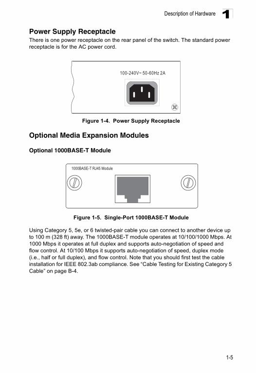
Power Supply ReceptacleThere is one power receptacle on the rear panel of the switch. The standard power receptacle is for the AC power cord.Figure 1-4. Power Supply Receptacle
Optional Media Expansion Modules
Optional 1000BASE-T Module
Figure 1-5. Single-Port 1000BASE-T Module
Using Category 5, 5e, or 6 twisted-pair cable you can connect to another device up to 100 m (328 ft) away. The 1000BASE-T module operates at 10/100/1000 Mbps. At 1000 Mbps it operates at full duplex and supports auto-negotiation of speed and flow control. At 10/100 Mbps it supports auto-negotiation of speed, duplex mode (i.e., half or full duplex), and flow control. Note that you should first test the cable installation for IEEE 802.3ab compliance. See “Cable Testing for Existing Category 5 Cable” on page B-4.
100-240V~ 50-60Hz 2A
1000BASE-T RJ45 Module
1-5

Introduction1
Optional 1000BASE-SX ModuleFigure 1-6. Single-Port 1000BASE-SX Gigabit Module
Using multimode fiber optic cable, the 1000BASE-SX port can be connected to a remote site up to 550 m (1805 ft) away. The 1000BASE-SX Gigabit module operates at 1 Gbps, with support for full-duplex mode and flow control.
Optional 1000BASE-LX Module
Figure 1-7. Single-Port 1000BASE-LX Gigabit Module
Using single-mode fiber optic cable, the 1000BASE-LX port can be connected to a remote site up to 5 km (16404 ft) away. The 1000BASE-LX Gigabit module operates at 1 Gbps, with support for full-duplex mode and flow control.
Optional 100BASE-FX Multimode Module
Figure 1-8. Single-Port 100BASE-FX Multimode Module
Using multimode fiber optic cable, the 100BASE-FX port can be connected to a remote site up to 2 km (1.24 miles) away. The 100BASE-FX module is fixed to operate at 100 Mbps full duplex, and supports auto-negotiation for flow control. The module is fitted with an SC connector.
RXTX
1000BASE-SX Multimode Module
RXTX
1000BASE-LX Singlemode Module
RXTX
100BASE-FX Multimode Module
1-6

Description of Hardware 1
Optional 100BASE-FX Single-mode ModuleFigure 1-9. Single-Port 100BASE-FX Single-mode Module
Using fiber optic cable, the 100BASE-FX port can be connected to a remote site up to 20 km (12.43 miles) away. The 100BASE-FX module is fixed to operate at 100 Mbps full duplex, and supports auto-negotiation for flow control. The module is fitted with an SC connector.
Optional 1000BASE-X GBIC Module
Figure 1-10. Single-Port 1000BASE-X GBIC Module
The slot on the front panel can be used for a single-port GBIC transceiver. This module supports 5 V 1000BASE-SX, 1000BASE-LX and 1000BASE-LH GBIC transceivers (purchased separately).
RXTX
1000BASE-SX Singlemode Module
1000BASE-X GBIC Module
1-7
Introduction1
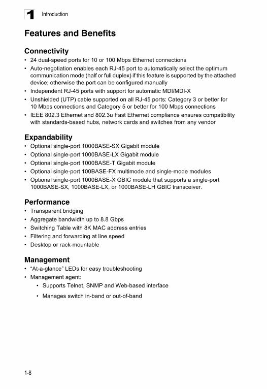
Features and BenefitsConnectivity• 24 dual-speed ports for 10 or 100 Mbps Ethernet connections• Auto-negotiation enables each RJ-45 port to automatically select the optimum
communication mode (half or full duplex) if this feature is supported by the attached device; otherwise the port can be configured manually
• Independent RJ-45 ports with support for automatic MDI/MDI-X• Unshielded (UTP) cable supported on all RJ-45 ports: Category 3 or better for
10 Mbps connections and Category 5 or better for 100 Mbps connections• IEEE 802.3 Ethernet and 802.3u Fast Ethernet compliance ensures compatibility
with standards-based hubs, network cards and switches from any vendor
Expandability• Optional single-port 1000BASE-SX Gigabit module• Optional single-port 1000BASE-LX Gigabit module• Optional single-port 1000BASE-T Gigabit module• Optional single-port 100BASE-FX multimode and single-mode modules• Optional single-port 1000BASE-X GBIC module that supports a single-port
1000BASE-SX, 1000BASE-LX, or 1000BASE-LH GBIC transceiver.
Performance• Transparent bridging• Aggregate bandwidth up to 8.8 Gbps• Switching Table with 8K MAC address entries• Filtering and forwarding at line speed• Desktop or rack-mountable
Management• “At-a-glance” LEDs for easy troubleshooting• Management agent:
• Supports Telnet, SNMP and Web-based interface
• Manages switch in-band or out-of-band
1-8
Chapter 2: Network Planning
Introduction to SwitchingA network switch allows simultaneous transmission of multiple packets via non-crossbar switching. This means that it can partition a network more efficiently than bridges or routers. The switch has, therefore, been recognized as one of the most important building blocks for today’s networking technology.
When performance bottlenecks are caused by congestion at the network access point (such as the network card for a high-volume file server), the device experiencing congestion (server, power user or hub) can be attached directly to a switched port. And, by using full-duplex mode, the bandwidth of the dedicated segment can be doubled to maximize throughput.
When networks are based on repeater (hub) technology, the maximum distance between end stations is limited. For Ethernet, there may be up to four hubs between any pair of stations; for Fast Ethernet, the maximum is two. This is known as the hop count. However, a switch turns the hop count back to zero. So subdividing the network into smaller and more manageable segments, and linking them to the larger network by means of a switch, removes this limitation.
A switch can be easily configured in any Ethernet or Fast Ethernet network to significantly boost bandwidth while using conventional cabling and network cards.
2-1

Network Planning2
Application ExamplesThis switch is not only designed to segment your network, but also to provide a wide range of options in setting up network connections. Some typical applications are described below.Collapsed BackboneThis switch is an excellent choice for mixed Ethernet and Fast Ethernet installations where significant growth is expected in the near future. You can easily build on this basic configuration, adding direct full-duplex connections to workstations or servers. When the time comes for further expansion, just cascade the switch to an Ethernet or Fast Ethernet hub or switch.
In the figure below, this switch is operating as a collapsed backbone for a small LAN. It is providing dedicated 10 Mbps full-duplex connections to workstations and 100 Mbps full-duplex connections to power users and servers.
Figure 2-1. Collapsed Backbone
Servers100 MbpsFull Duplex
Workstations100 MbpsFull Duplex
Workstations10 MbpsFull Duplex
... ... ...
PWR
Diag
M1
M2
Module 2Module 112
34
56
78
910
1112
1314
1516
1718
1920
2122
2324
Console
2-2

Application Examples 2
Network Aggregation PlanWith 26 parallel bridging ports (i.e., 26 distinct collision domains), this switch can collapse a complex network down into a single efficient bridged node, increasing overall bandwidth and throughput.In the figure below, the 10BASE-T/100BASE-TX ports on the switch are providing 100 Mbps connectivity for up to 24 segments. In addition, the switch is also connecting servers at 100 Mbps.
Figure 2-2. Network Aggregation Plan
Server Farm
10/100 Mbps Segments
... ...
PWR
Diag
M1
M2
Module 2Module 112
34
56
78
910
1112
1314
1516
1718
1920
2122
2324
Console
2-3

Network Planning2
Remote Connection with Fiber CableFiber optic technology allows for longer cabling than any other media type. A 100 Mbps multimode fiber (MMF) link can run up to 2 km, and a 100 Mbps single-mode fiber (SMF) link can run as far as 20 km. A 1000BASE-SX (MMF) link can connect to a site up to 550 meters away, and a 1000BASE-LX (SMF) link can run up to 5 km. This allows the switch to serve as a collapsed backbone, providing direct connectivity for a widespread LAN.The 100BASE-FX (SMF) plug-in module or 1000BASE-LH GBIC transceiver can be used to interconnect remote network segments. While a 1000BASE-SX module can be used for a high-speed connection between floors in the same building, and a 1000BASE-LX module can be used to connect to other buildings in a campus setting.
The figure below illustrates this switch connecting to a remote segment with fiber cable.
Figure 2-3. Remote Connection with Fiber Cable
Server Farm
...
Remote Switch
1000BASE-LX SMF(5 kilometers)
Headquarters
1 2 3 4 5 6 7 8 9 10 11 12
13 14 15 16 17 18 19 20 21 22 23 24
Status
Link
Link
Status
Status
13
1
14 15 16 17 18 19 20 21 22 23 24 M2
M1
FDX
ACT
COL
100M
Power
RPU
SNMP
Console
2 3 4 5 6 7 8 9 10 11 12
ES3627
PWR
Diag
M1
M2
Module 2Module 112
34
56
78
910
1112
1314
1516
1718
1920
2122
2324
Console
2-4

Application Examples 2
Making VLAN ConnectionsThis switch supports VLANs which can be used to organize any group of network nodes into separate broadcast domains. VLANs confine broadcast traffic to the originating group, and can eliminate broadcast storms in large networks. This provides a more secure and cleaner network environment.VLANs can be based on untagged port groups, or traffic can be explicitly tagged to identify the VLAN group to which it belongs. Unttagged VLANs can be used for small networks attached to a single switch. However, tagged VLANs should be used for larger networks, and all the VLANs assigned to the inter-switch links.
The switch also supports multiple spanning trees which allow VLANs groups to maintain a more stable path between all VLAN members. This can reduce the overall amount of protocol traffic crossing the network, and provide a shorter reconfiguration time when any link in the spanning tree fails.
Figure 2-4. Making VLAN Connections
Finance
Marketing
VLAN 3
Untagged Ports
VLANunawareswitch
Tagged Port
VLANawareswitch
TaggedPorts
Finance
VLAN 3
R&D
VLAN 2Testing R&D
Testing
VLAN 1
VLAN 2VLAN 4
VLAN 1
PWR
Diag
M1
M2
Module 2Module 112
34
56
78
910
1112
1314
1516
1718
1920
2122
2324
Console
2-5

Network Planning2
Application Notes1. Full-duplex operation only applies to point-to-point access (such as when aswitch is attached to a workstation, server or another switch). When the switch is connected to a hub, both devices must operate in half-duplex mode.
2. Avoid using flow control on a port connected to a hub unless it is actually required to solve a problem. Otherwise back pressure jamming signals may degrade overall performance for the segment attached to the hub.
3. As a general rule the length of fiber optic cable for a single switched link should not exceed:
• 1000BASE-SX/LX: 550 m (1805 ft) for multimode fiber or 5 km (16404 ft) for single-mode fiber.
• 100BASE-FX: 2 km (1.24 miles) for multimode fiber or 20 km (2.43 miles) for single-mode fiber.
However, power budget constraints must also be considered when calculating the maximum cable length for your specific environment.
2-6
Chapter 3: Installing the Switch
Selecting a SiteSwitch units can be mounted in a standard 19-inch equipment rack or on a flat surface. Be sure to follow the guidelines below when choosing a location.
• The site should:• be at the center of all the devices you want to link and near a power outlet
• be able to maintain its temperature within 0 to 50° C (32 to 122 °F) and its humidity within 10% to 90%, non-condensing
• provide adequate space (approximately two inches) on all sides for proper air flow
• be accessible for installing, cabling and maintaining the devices
• allow the status LEDs to be clearly visible
• Make sure twisted-pair cable is always routed away from power lines, fluorescent lighting fixtures and other sources of electrical interference, such as radios, transmitters, etc.
• Make sure that the unit is connected to a separate grounded power outlet that provides 100 to 240 VAC, 50 to 60 Hz, is within 2.44 m (8 feet) of each device and is powered from an independent circuit breaker. As with any equipment, using a filter or surge suppressor is recommended.
Ethernet CablingTo ensure proper operation when installing the switch into a network, make sure that the current cables are suitable for 10BASE-T or 100BASE-TX operation. Check the following criteria against the current installation of your network:
• Cable type: Unshielded twisted pair (UTP) or shielded twisted pair (STP) cables with RJ-45 connectors; Category 3 or better for 10BASE-T and Category 5 or better for 100BASE-TX.
• Protection from radio frequency interference emissions• Electrical surge suppression• Separation of electrical wires (switch related or other) and electromagnetic fields
from data based network wiring• Safe connections with no damaged cables, connectors or shields
3-1

Installing the Switch3
Figure 3-1. RJ-45 Connections
Equipment ChecklistAfter unpacking the switch, check the contents to be sure you have received all the components. Then, before beginning the installation, be sure you have all other necessary installation equipment.
Package Contents• 24-Port Intelligent Workgroup Switch• Four adhesive foot pads• Bracket Mounting Kit containing two brackets and eight screws for attaching the
brackets to the switch• Power Cord—either US, Continental Europe or UK• RS-232 console cable• This Installation Guide• Management Guide
Optional Rack-Mounting EquipmentIf you plan to rack-mount the switch, be sure to have the following equipment available:
• Four mounting screws for each device you plan to install in a rack—these are not included
• A screwdriver (Phillips or flathead, depending on the type of screws used)
RJ-45 Connector
3-2
Mounting 3
MountingA switch unit can be mounted in a standard 19-inch equipment rack or on a desktop or shelf. Mounting instructions for each type of site follow.Installing Optional Modules: Before mounting the switch, be sure you install any optional modules. If you have purchased optional slide-in 1000BASE-T, 1000BASE-SX, 1000BASE-LX, 100BASE-FX or GBIC media expansion module, install these modules now, following the instructions “Installing an Optional Module into the Switch” on page 3-5.
Rack MountingBefore rack mounting the switch, pay particular attention to the following factors:
• Temperature: Since the temperature within a rack assembly may be higher than the ambient room temperature, check that the rack-environment temperature is within the specified operating temperature range. (See page C-1.)
• Mechanical Loading: Do not place any equipment on top of a rack-mounted unit.• Circuit Overloading: Be sure that the supply circuit to the rack assembly is not
overloaded.• Grounding: Rack-mounted equipment should be properly grounded. Particular
attention should be given to supply connections other than direct connections to the mains.
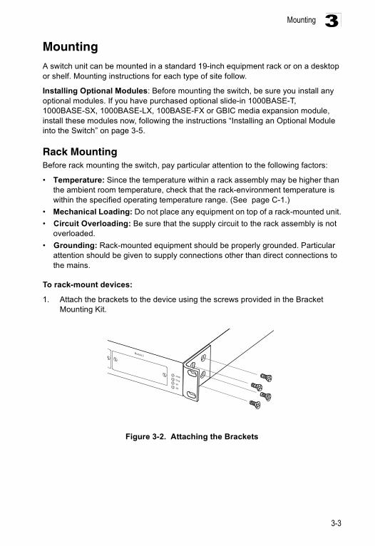
To rack-mount devices:
1. Attach the brackets to the device using the screws provided in the Bracket Mounting Kit.
Figure 3-2. Attaching the Brackets
PWR
Diag
M1
M2
Module 2
3-3

Installing the Switch3
2. Mount the device in the rack, using four rack-mounting screws (not provided).Figure 3-3. Installing the Switch in a Rack
3. If installing a single switch only, turn to “Connecting to a Power Source” at the end of this chapter.
4. If installing multiple switches, mount them in the rack, one below the other, in any order.
Desktop or Shelf Mounting1. Attach the four adhesive feet to the bottom of the first switch.
Figure 3-4. Attaching the Adhesive Feet
2. Set the device on a flat surface near an AC power source, making sure there are at least two inches of space on all sides for proper air flow.
PWR
Diag
M1
M2
Module 2
PWR
Diag
M1
M2
Module2
Module1
123
4567
891011
12131415
16171819
20212223
24
Console
3-4
Installing an Optional Module into the Switch 3
3. If installing a single switch only, go to “Connecting to a Power Source” at theend of this chapter.
4. If installing multiple switches, attach four adhesive feet to each one. Place each device squarely on top of the one below, in any order.
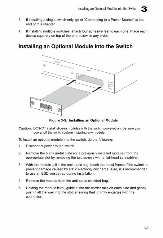
Installing an Optional Module into the Switch
Figure 3-5. Installing an Optional Module
Caution: DO NOT install slide-in modules with the switch powered on. Be sure you power off the switch before installing any module.
To install an optional module into the switch, do the following:
1. Disconnect power to the switch.
2. Remove the blank metal plate (or a previously installed module) from the appropriate slot by removing the two screws with a flat-head screwdriver.
3. With the module still in the anti-static bag, touch the metal frame of the switch to prevent damage caused by static electricity discharge. Also, it is recommended to use an ESD wrist strap during installation.
4. Remove the module from the anti-static shielded bag.
5. Holding the module level, guide it into the carrier rails on each side and gently push it all the way into the slot, ensuring that it firmly engages with the connector.
PWR
Diag
M1
M2
Module 2
Module 1
100BASE-FX Singlemode Module
RXTX
3-5
Installing the Switch3
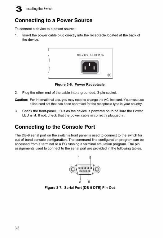
Connecting to a Power SourceTo connect a device to a power source:1. Insert the power cable plug directly into the receptacle located at the back of the device.
Figure 3-6. Power Receptacle
2. Plug the other end of the cable into a grounded, 3-pin socket.
Caution: For International use, you may need to change the AC line cord. You must use a line cord set that has been approved for the receptacle type in your country.
3. Check the front-panel LEDs as the device is powered on to be sure the Power LED is lit. If not, check that the power cable is correctly plugged in.
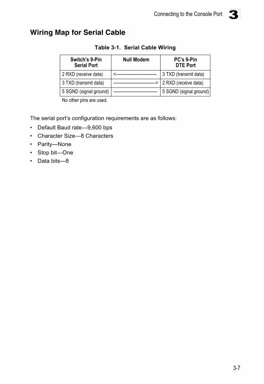
Connecting to the Console Port The DB-9 serial port on the switch’s front panel is used to connect to the switch for out-of-band console configuration. The command-line configuration program can be accessed from a terminal or a PC running a terminal emulation program. The pin assignments used to connect to the serial port are provided in the following tables.
Figure 3-7. Serial Port (DB-9 DTE) Pin-Out
100-240V~ 50-60Hz 2A
1 5
6 9
3-6
Connecting to the Console Port 3
Wiring Map for Serial CableTable 3-1. Serial Cable Wiring
The serial port’s configuration requirements are as follows:
• Default Baud rate—9,600 bps• Character Size—8 Characters• Parity—None• Stop bit—One• Data bits—8
Switch’s 9-Pin Serial Port
Null Modem PC’s 9-Pin DTE Port
2 RXD (receive data) <---------------------------- 3 TXD (transmit data)3 TXD (transmit data) -----------------------------> 2 RXD (receive data)5 SGND (signal ground) ------------------------------ 5 SGND (signal ground)No other pins are used.
3-7

Installing the Switch3
3-8
Chapter 4: Making Network Connections
Connecting Network DevicesThe switch may be connected to 10 or 100 Mbps network cards in PCs and servers, as well as to other switches and hubs. It may also be connected to remote devices using the optional fiber optic modules.
Twisted-Pair DevicesEach device requires a shielded or unshielded twisted-pair (STP or UTP) cable with RJ-45 connectors at both ends. For 1000BASE-T Category 5, 5e, or 6 cable is required, for 100BASE-TX connections, Category 5 or better cable is required; for 10BASE-T, Category 3 or better cable can be used.
Cabling GuidelinesA twisted-pair connection between two ports must have a crossover of the transmit and receive wires to be able to function. This crossover can be implemented in either of the ports, or in the cable connecting them.
Network card ports in PCs and servers do not contain an internal wiring crossover, these are known as straight-through (MDI) ports. Therefore, most switch and hub ports implement a built-in crossover — known as fixed crossover (MDI-X) ports — so that they can be connected to PCs and servers using standard straight-through cable. Some switches and hubs also have an MDI port, so that they can connect to another switch’s/hub’s MDI-X port using straight-through cable. To connect between two switches/hubs that only have fixed MDI-X ports, the wiring crossover must be implemented in the cable — known as a crossover cable.
The RJ-45 ports on the switch base unit support automatic MDI/MDI-X operation, which means that they automatically detect the wiring in the link and configure as MDI or MDI-X accordingly. So for these ports, you can use standard straight-through twisted-pair cables to connect to any other network device (PCs, servers, switches, hubs, or routers). However, note that auto-negotiation must be enabled on these ports for automatic wiring configuration to function properly.
4-1

Making Network Connections4
Connecting to PCs, Servers, Hubs and SwitchesCaution: Do not plug a phone jack connector into an RJ-45 port. This will damage theswitch. Use only twisted-pair cables with RJ-45 connectors that conform to FCC standards.
1. Attach one end of a twisted-pair cable segment to the device’s RJ-45 connector.
Figure 4-1. Making Twisted-Pair Connections
2. If the device is a PC card and the switch is in the wiring closet, attach the other end of the cable segment to a modular wall outlet that is connected to the wiring closet. (See “Wiring Closet Connections” on the next page.) Otherwise, attach the other end to an available port on the switch.
3. Make sure each twisted pair cable does not exceed 100 meters (328 ft) in length.
Note: Avoid using flow control on a port connected to a hub unless it is actually required to solve a problem. Otherwise back pressure jamming signals may degrade overall performance for the segment attached to the hub.
4. As each connection is made, the green Link LED (on the switch) corresponding to each port will light to indicate that the connection is valid.
4-2
Twisted-Pair Devices 4
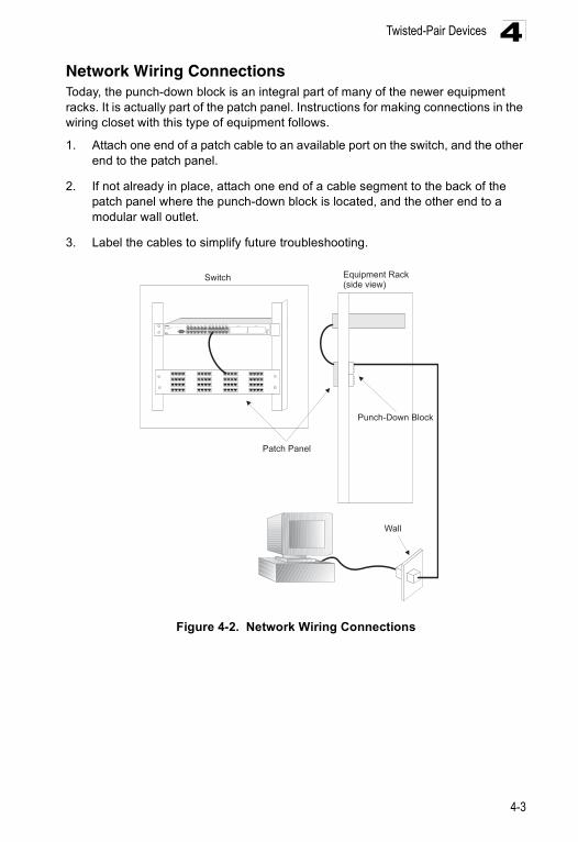
Network Wiring ConnectionsToday, the punch-down block is an integral part of many of the newer equipment racks. It is actually part of the patch panel. Instructions for making connections in the wiring closet with this type of equipment follows.1. Attach one end of a patch cable to an available port on the switch, and the other end to the patch panel.
2. If not already in place, attach one end of a cable segment to the back of the patch panel where the punch-down block is located, and the other end to a modular wall outlet.
3. Label the cables to simplify future troubleshooting.
Figure 4-2. Network Wiring Connections
Equipment Rack(side view)
Switch
Patch Panel
Punch-Down Block
Wall
PWR
Diag
M1
M2
Module 2Module 112
34
56
78
910
1112
1314
1516
1718
1920
2122
2324
Console
4-3

Making Network Connections4
Fiber Optic DevicesAn optional slide-in 1000BASE-SX, 1000BASE-LX, or 100BASE-FX module may be used for backbone and long distance connections. A 1000BASE-SX, or 1000BASE-LX module may also be used for connecting to a high-speed server.Each single-mode fiber optic port requires 9/125 micron multimode fiber optic cabling with an SC connector at both ends. Each multimode fiber optic port requires 50/125 or 62.5/125 micron multimode fiber optic cabling with an SC connector at both ends.
Caution: This switch uses lasers to transmit signals over fiber optic cable. The lasers are compliant with the requirements of a Class 1 Laser Product and are inherently eye safe in normal operation. However, you should never look directly at a transmit port when it is powered on.
1. Remove and keep the SC port’s rubber plug. When not connected to a fiber cable, the rubber plug should be replaced to protect the optics.
2. Check that the fiber terminators are clean. You can clean the cable plugs by wiping them gently with a clean tissue or cotton ball moistened with a little ethanol. Dirty fiber terminators on fiber optic cables will impair the quality of the light transmitted through the cable and lead to degraded performance on the port.
3. Connect one end of the cable to the SC port on the switch and the other end to the SC port on the other device. Since SC connectors are keyed, the cable can be attached in only one orientation.
Figure 4-3. Making SC Port Connections
4. As a connection is made, check the LED on the switch’s front panel for the corresponding module to be sure that the connection is valid.
Note: If you use an SC-ST converter, be sure to connect the converter’s Tx (Rx) port to the Rx (Tx) port on the other device.
PWR
Diag
M1
M2
Module 2
Module 1
100BASE-FX Singlemode Module
RXTX
SC fiber connector
4-4

Connectivity Rules 4
Connectivity RulesWhen adding hubs (repeaters) to your network, please follow the connectivity rules listed in the manuals for these products. However, note that because switches break up the path for connected devices into separate collision domains, you should not include the switch or connected cabling in your calculations for cascade length involving other devices.1000BASE-T Cable RequirementsAll Category 5 UTP cables that are used for 100BASE-TX connections should also work for 1000BASE-T, providing that all four wire pairs are connected. However, it is recommended that for all critical connections, or any new cable installations, Category 5e (enhanced Category 5) or Category 6 cable should be used. The Category 5e specification includes test parameters that are only recommendations for Category 5. Therefore, the first step in preparing existing Category 5 cabling for running 1000BASE-T is a simple test of the cable installation to be sure that it complies with the IEEE 802.3ab standards.
1000 Mbps Gigabit Ethernet Collision Domain
Table 4-1. Maximum 1000BASE-T Gigabit Ethernet Cable Length
Table 4-2. Maximum 1000BASE-SX Gigabit Ethernet Cable Length
Table 4-3. Maximum 1000BASE-LX Gigabit Ethernet Cable Length
Table 4-4. Maximum 1000BASE-LH Gigabit Ethernet Cable Length
Cable Type Maximum Cable Length ConnectorCategory 5, 5e, 6 100-ohm UTP or STP 100 m (328 ft) RJ-45
Fiber Size Fiber Bandwidth Maximum Cable Length Connector62.5/125 micron multimode fiber
160 MHz/km 2-220 m (7-722 ft) SC or ST200 MHz/km 2-275 m (7-902 ft) SC or ST
50/125 micron multimode fiber
400 MHz/km 2-500 m (7-1641 ft) SC or ST500 MHz/km 2-550 m (7-1805 ft) SC or ST
Fiber Size Fiber Bandwidth Maximum Cable Length Connector9/125 micron single-mode fiber
N/A 2 m - 5 km (7 ft - 3.2 miles) SC or ST
Fiber Size Fiber Bandwidth Cable Length Range9/125 micron single-mode fiber N/A 70 km (43 miles)
4-5

Making Network Connections4
100 Mbps Fast Ethernet Collision DomainTable 4-5. Maximum Fast Ethernet Cable Distance
10 Mbps Ethernet Collision Domain
Table 4-6. Maximum Ethernet Cable Distance
Cable Labeling and Connection RecordsWhen planning a network installation, it is essential to label the opposing ends of cables and to record where each cable is connected. Doing so will enable you to easily locate inter-connected devices, isolate faults and change your topology without need for unnecessary time consumption.
To best manage the physical implementations of your network, follow these guidelines:
• Clearly label the opposing ends of each cable.• Using your building’s floor plans, draw a map of the location of all
network-connected equipment. For each piece of equipment, identify the devices to which it is connected.
• Note the length of each cable and the maximum cable length supported by the switch ports.
• For ease of understanding, use a location-based key when assigning prefixes to your cable labeling.
• Use sequential numbers for cables that originate from the same equipment.• Differentiate between racks by naming accordingly.• Label each separate piece of equipment.• Display a copy of your equipment map, including keys to all abbreviations at each
equipment rack.
Type Cable Type Max. Cable Length Connector
100BASE-TX Category 5 or better 100-ohm UTP or STP 100 m (328 ft) RJ-45
100BASE-FX Multimode
50/125 or 62.5/125 micron core multimode fiber (MMF)
2 km (1.24 miles) SC or ST
100BASE-FX Single-Mode
9/125 micron core single-mode fiber (SMF) 20 km (12.43 miles) SC or ST
Cable Type Maximum Length ConnectorTwisted Pair, Categories 3, 4, 5 or better 100-ohm UTP
100 m (328 ft) RJ-45
4-6

Appendix A: Troubleshooting
Diagnosing Switch Indicators
Table A-1. Troubleshooting Chart
Power and Cooling ProblemsIf the power indicator does not turn on when the power cord is plugged in, you may have a problem with the power outlet, power cord, or internal power supply. However, if the unit powers off after running for a while, check for loose power connections, power losses or surges at the power outlet, and verify that the fans on the unit are unobstructed and running prior to shutdown. If you still cannot isolate the problem, then the internal power supply may be defective.
InstallationVerify that all system components have been properly installed. If one or more components appear to be malfunctioning (such as the power cord or network cabling), test them in an alternate environment where you are sure that all the other components are functioning properly.
In-Band AccessYou can access the management agent in the switch from anywhere within the attached network using Telnet, a Web browser, or other network management software tools. However, you must first configure the switch with a valid IP address,
Troubleshooting ChartSymptom ActionPower LED is Off • Check connections between the switch, the power cord, and the wall
outlet.• Contact your dealer for assistance.
Diag LED is On Amber • The switch has deteced a fault. Try power cycling the switch to clear the condition.
• If the condition persists, contact your dealer for assistance.Link LED is Off • Verify that the switch and attached device are powered on.
• Be sure the cable is plugged into both the switch and corresponding device.
• Verify that the proper cable type is used and its length does not exceed specified limits.
• Check the adapter on the attached device and cable connections for possible defects. Replace the defective adapter or cable if necessary.
A-1

TroubleshootingA
subnet mask, and default gateway. If you have trouble establishing a link to the management agent, check to see if you have a valid network connection. Then verify that you entered the correct IP address. Also, be sure the port through which you are connecting to the switch has not been disabled. If it has not been disabled, then check the network cabling that runs between your remote location and the switch.Caution: The management agent can accept up to four simultaneous Telnet sessions. If the maximum number of sessions already exists, an additional Telnet connection will not be able to log into the system.
A-2
Appendix B: Cables
Twisted-Pair Cable and Pin AssignmentsCaution: DO NOT plug a phone jack connector into any RJ-45 port. Use only
twisted-pair cables with RJ-45 connectors that conform with FCC standards.
For 10BASE-T/100BASE-TX connections, a twisted-pair cable must have two pairs of wires. Each wire pair is identified by two different colors. For example, one wire might be green and the other, green with white stripes. Also, an RJ-45 connector must be attached to both ends of the cable.
Caution: Each wire pair must be attached to the RJ-45 connectors in a specific orientation. (See “Cabling Guidelines” on page 4-1 for an explanation.)
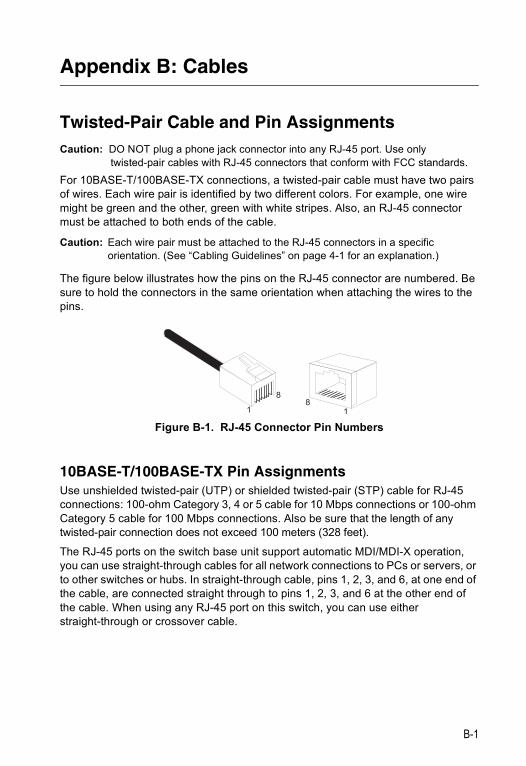
The figure below illustrates how the pins on the RJ-45 connector are numbered. Be sure to hold the connectors in the same orientation when attaching the wires to the pins.
Figure B-1. RJ-45 Connector Pin Numbers
10BASE-T/100BASE-TX Pin AssignmentsUse unshielded twisted-pair (UTP) or shielded twisted-pair (STP) cable for RJ-45 connections: 100-ohm Category 3, 4 or 5 cable for 10 Mbps connections or 100-ohm Category 5 cable for 100 Mbps connections. Also be sure that the length of any twisted-pair connection does not exceed 100 meters (328 feet).
The RJ-45 ports on the switch base unit support automatic MDI/MDI-X operation, you can use straight-through cables for all network connections to PCs or servers, or to other switches or hubs. In straight-through cable, pins 1, 2, 3, and 6, at one end of the cable, are connected straight through to pins 1, 2, 3, and 6 at the other end of the cable. When using any RJ-45 port on this switch, you can use either straight-through or crossover cable.
B-1
CablesB
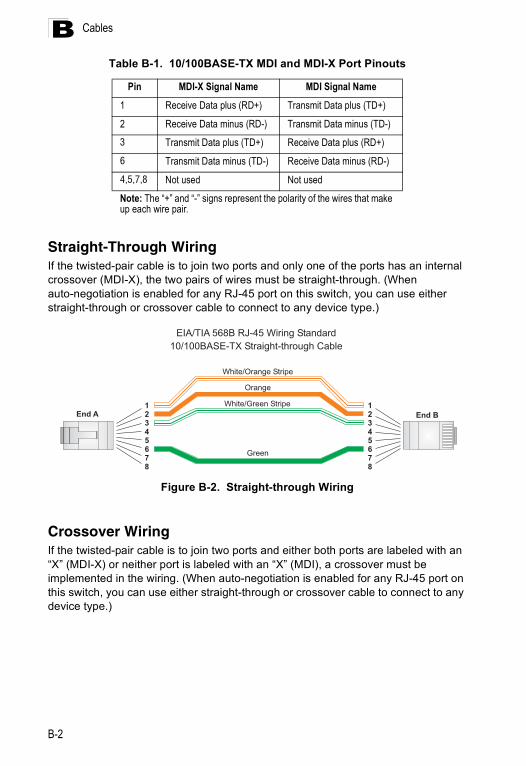
Table B-1. 10/100BASE-TX MDI and MDI-X Port PinoutsStraight-Through WiringIf the twisted-pair cable is to join two ports and only one of the ports has an internal crossover (MDI-X), the two pairs of wires must be straight-through. (When auto-negotiation is enabled for any RJ-45 port on this switch, you can use either straight-through or crossover cable to connect to any device type.)
Figure B-2. Straight-through Wiring
Crossover WiringIf the twisted-pair cable is to join two ports and either both ports are labeled with an “X” (MDI-X) or neither port is labeled with an “X” (MDI), a crossover must be implemented in the wiring. (When auto-negotiation is enabled for any RJ-45 port on this switch, you can use either straight-through or crossover cable to connect to any device type.)
Pin MDI-X Signal Name MDI Signal Name
1 Receive Data plus (RD+) Transmit Data plus (TD+)
2 Receive Data minus (RD-) Transmit Data minus (TD-)3 Transmit Data plus (TD+) Receive Data plus (RD+)6 Transmit Data minus (TD-) Receive Data minus (RD-)4,5,7,8 Not used Not used
Note: The “+” and “-” signs represent the polarity of the wires that make up each wire pair.
White/Orange Stripe
Orange
White/Green Stripe
Green
1
2
3
4
5
6
7
8
1
2
3
4
5
6
7
8
EIA/TIA 568B RJ-45 Wiring Standard
10/100BASE-TX Straight-through Cable
End A End B
B-2

Twisted-Pair Cable and Pin Assignments B
Figure B-3. Crossover Wiring
1000BASE-T Pin AssignmentsAll 1000BASE-T ports support automatic MDI/MDI-X operation, so you can use straight-through cables for all network connections to PCs or servers, or to other switches or hubs.
The table below shows the 1000BASE-T MDI and MDI-X port pinouts. These ports require that all four pairs of wires be connected. Note that for 1000BASE-T operation, all four pairs of wires are used for both transmit and receive.
Use 100-ohm Category 5, 5e or 6 unshielded twisted-pair (UTP) or shielded twisted-pair (STP) cable for 1000BASE-T connections. Also be sure that the length of any twisted-pair connection does not exceed 100 meters (328 feet).
Table B-2. 1000BASE-T MDI-X and MDI Port Pinouts
1000BASE-T MDI-X and MDI Port PinoutsPin MDI-X Signal Name MDI Signal Name
1 Bi-directional Data Two Plus (BI_D2+) Bi-directional Data One Plus (BI_D1+)
2 Bi-directional Data Two Minus (BI_D2-) Bi-directional Data One Minus (BI_D1-)
3 Bi-directional Data One Plus (BI_D1+) Bi-directional Data Two Plus (BI_D2+)
4 Bi-directional Data Four Plus (BI_D4+) Bi-directional Data Three Plus (BI_D3+)
5 Bi-directional Data Four Minus (BI_D4-) Bi-directional Data Three Minus (BI_D3-)
6 Bi-directional Data One Minus (BI_D1-) Bi-directional Data Two Minus (BI_D2-)
7 Bi-directional Data One Plus (BI_D3+) Bi-directional Data One Plus (BI_D4+)
8 Bi-directional Data Three Minus (BI_D3-) Bi-directional Data Four Minus (BI_D4-)
White/Orange Stripe
Orange
White/Green Stripe
Green
1
2
3
4
5
6
7
8
1
2
3
4
5
6
7
8
EIA/TIA 568B RJ-45 Wiring Standard
10/100BASE-TX Crossover Cable
End A End B
B-3
CablesB
Cable Testing for Existing Category 5 CableInstalled Category 5 cabling must pass tests for Attenuation, Near-End Crosstalk (NEXT), and Far-End Crosstalk (FEXT). This cable testing information is specified in the ANSI/TIA/EIA-TSB-67 standard. Additionally, cables must also pass test parameters for Return Loss and Equal-Level Far-End Crosstalk (ELFEXT). These tests are specified in the ANSI/TIA/EIA-TSB-95 Bulletin, “The Additional Transmission Performance Guidelines for 100 Ohm 4-Pair Category 5 Cabling.”Note that when testing your cable installation, be sure to include all patch cables between switches and end devices.
Adjusting Existing Category 5 Cabling to Run 1000BASE-TIf your existing Category 5 installation does not meet one of the test parameters for 1000BASE-T, there are basically three measures that can be applied to try and correct the problem:
1. Replace any Category 5 patch cables with high-performance Category 5e or Category 6 cables.
2. Reduce the number of connectors used in the link.
3. Reconnect some of the connectors in the link.
Fiber StandardsThe current TIA (Telecommunications Industry Association) 568-A specification on optical fiber cabling consists of one recognized cable type for horizontal subsytems and two cable types for backbone subsystems.
Horizontal 62.5/125 micron multimode (two fibers per outlet).Backbone 62.5/125 micron multimode or singlemode.
TIA 568-B will allow the use of 50/125 micron multimode optical fiber in both the horizontal and backbone in addition to the types listed above. All optical fiber components and installation practices must meet applicable building and safety codes.
B-4
Appendix C: Specifications
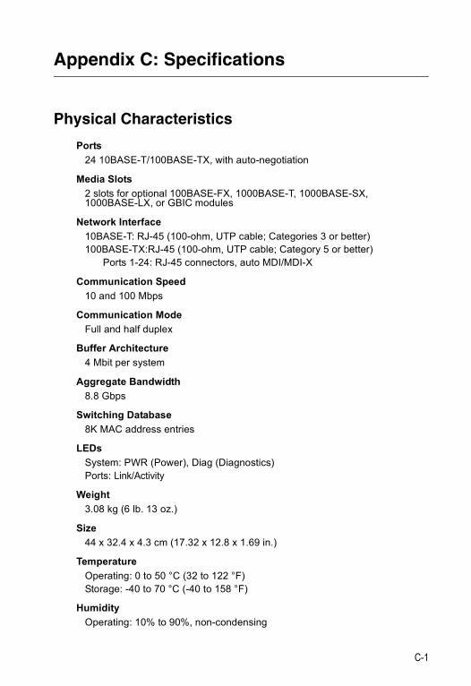
Physical Characteristics
Ports24 10BASE-T/100BASE-TX, with auto-negotiation
Media Slots2 slots for optional 100BASE-FX, 1000BASE-T, 1000BASE-SX, 1000BASE-LX, or GBIC modules
Network Interface10BASE-T: RJ-45 (100-ohm, UTP cable; Categories 3 or better)100BASE-TX:RJ-45 (100-ohm, UTP cable; Category 5 or better)
Ports 1-24: RJ-45 connectors, auto MDI/MDI-X
Communication Speed10 and 100 Mbps
Communication ModeFull and half duplex
Buffer Architecture4 Mbit per system
Aggregate Bandwidth8.8 Gbps
Switching Database8K MAC address entries
LEDs System: PWR (Power), Diag (Diagnostics)Ports: Link/Activity
Weight3.08 kg (6 lb. 13 oz.)
Size44 x 32.4 x 4.3 cm (17.32 x 12.8 x 1.69 in.)
TemperatureOperating: 0 to 50 °C (32 to 122 °F)Storage: -40 to 70 °C (-40 to 158 °F)
HumidityOperating: 10% to 90%, non-condensing
C-1
SpecificationsC
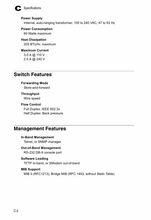
Power SupplyInternal, auto-ranging transformer: 100 to 240 VAC, 47 to 63 Hz
Power Consumption60 Watts maximum
Heat Dissipation205 BTU/hr. maximum
Maximum Current3.0 A @ 110 V2.0 A @ 240 V
Switch Features
Forwarding ModeStore-and-forward
ThroughputWire speed
Flow ControlFull Duplex: IEEE 802.3xHalf Duplex: Back pressure
Management Features
In-Band ManagementTelnet, or SNMP manager
Out-of-Band ManagementRS-232 DB-9 console port
Software LoadingTFTP in-band, or XModem out-of-band
MIB SupportMIB II (RFC1213), Bridge MIB (RFC 1493, without Static Table)
C-2
Standards C
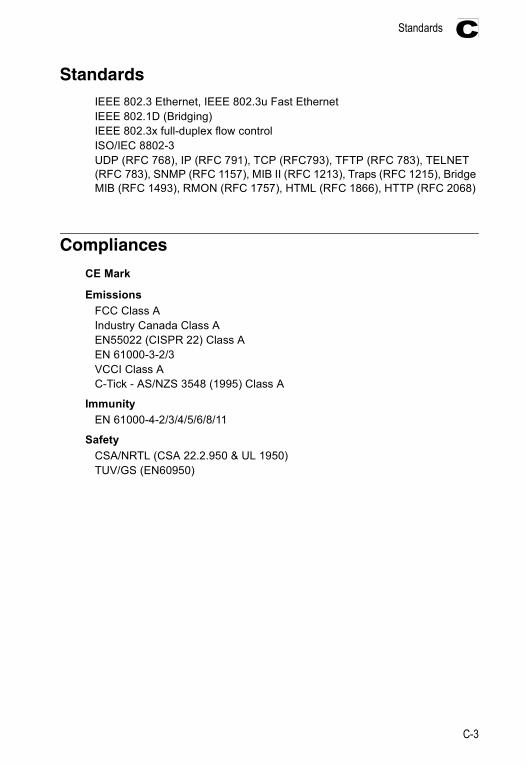
StandardsIEEE 802.3 Ethernet, IEEE 802.3u Fast EthernetIEEE 802.1D (Bridging)IEEE 802.3x full-duplex flow controlISO/IEC 8802-3UDP (RFC 768), IP (RFC 791), TCP (RFC793), TFTP (RFC 783), TELNET (RFC 783), SNMP (RFC 1157), MIB II (RFC 1213), Traps (RFC 1215), Bridge MIB (RFC 1493), RMON (RFC 1757), HTML (RFC 1866), HTTP (RFC 2068)
Compliances
CE Mark
EmissionsFCC Class AIndustry Canada Class AEN55022 (CISPR 22) Class AEN 61000-3-2/3VCCI Class AC-Tick - AS/NZS 3548 (1995) Class A
ImmunityEN 61000-4-2/3/4/5/6/8/11
SafetyCSA/NRTL (CSA 22.2.950 & UL 1950)TUV/GS (EN60950)
C-3
SpecificationsC
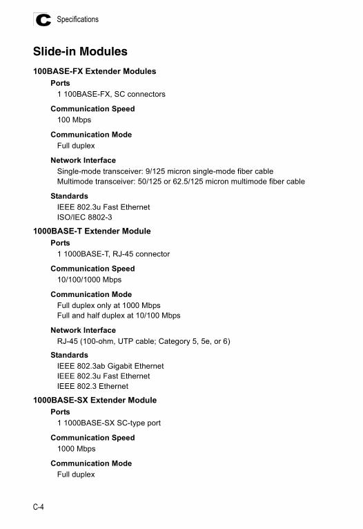
Slide-in Modules
100BASE-FX Extender ModulesPorts
1 100BASE-FX, SC connectors
Communication Speed100 Mbps
Communication ModeFull duplex
Network InterfaceSingle-mode transceiver: 9/125 micron single-mode fiber cableMultimode transceiver: 50/125 or 62.5/125 micron multimode fiber cable
StandardsIEEE 802.3u Fast EthernetISO/IEC 8802-3
1000BASE-T Extender ModulePorts
1 1000BASE-T, RJ-45 connector
Communication Speed10/100/1000 Mbps
Communication ModeFull duplex only at 1000 MbpsFull and half duplex at 10/100 Mbps
Network InterfaceRJ-45 (100-ohm, UTP cable; Category 5, 5e, or 6)
StandardsIEEE 802.3ab Gigabit EthernetIEEE 802.3u Fast EthernetIEEE 802.3 Ethernet
1000BASE-SX Extender ModulePorts
1 1000BASE-SX SC-type port
Communication Speed1000 Mbps
Communication ModeFull duplex
C-4
Slide-in Modules C
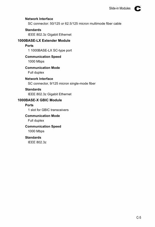
Network InterfaceSC connector: 50/125 or 62.5/125 micron multimode fiber cable
StandardsIEEE 802.3z Gigabit Ethernet
1000BASE-LX Extender ModulePorts
1 1000BASE-LX SC-type port
Communication Speed1000 Mbps
Communication ModeFull duplex
Network InterfaceSC connector, 9/125 micron single-mode fiber
Standards IEEE 802.3z Gigabit Ethernet
1000BASE-X GBIC Module Ports
1 slot for GBIC transceivers
Communication ModeFull duplex
Communication Speed1000 Mbps
StandardsIEEE 802.3z
C-5

SpecificationsC
C-6

Glossary
10BASE-TIEEE 802.3 specification for 10 Mbps Ethernet over two pairs of Category 3, 4, or 5 UTP cable.
100BASE-FXIEEE 802.3u specification for 100 Mbps Fast Ethernet over two strands of 50/125 or 62.5/125 micron core fiber cable.
100BASE-TXIEEE 802.3u specification for 100 Mbps Fast Ethernet over two pairs of Category 5 UTP cable.
1000BASE-LXIEEE 802.3z specification for Gigabit Ethernet over two strands of 9/125 micron core fiber cable.
1000BASE-LHLong-haul Gigabit Ethernet over two strands of 9/125 micron core fiber cable.
1000BASE-SXIEEE 802.3z specification for Gigabit Ethernet over two strands of 50/125 or62.5/125 micron core fiber cable.
1000BASE-TIEEE 802.3ab specification for Gigabit Ethernet over four pairs of Category 5, 5e, or 6 100-ohm UTP cable.
Auto-NegotiationSignalling method allowing each node to select its optimum operational mode (e.g., 10, 100, or 1000 Mbps and half or full duplex) based on the capabilities of the node to which it is connected.
BandwidthThe difference between the highest and lowest frequencies available for network signals. Also synonymous with wire speed, the actual speed of the data transmission along the cable.
CollisionA condition in which packets transmitted over the cable interfere with each other. Their interference makes both signals unintelligible.
Glossary-1

Glossary
Collision DomainSingle CSMA/CD LAN segment.
CSMA/CDCarrier Sense Multiple Access/Collision Detect is the communication method employed by Ethernet and Fast Ethernet.
End StationA workstation, server, or other device that does not act as a network interconnection.
EthernetA network communication system developed and standardized by DEC, Intel, and Xerox, using baseband transmission, CSMA/CD access, logical bus topology, and coaxial cable. The successor IEEE 802.3 standard provides for integration into the OSI model and extends the physical layer and media with repeaters and implementations that operate on fiber, thin coax and twisted-pair cable.
Fast EthernetA 100 Mbps network communication system based on Ethernet and the CSMA/CD access method.
Fast Ethernet SwitchDevice that provides a full 100 Mbps bandwidth (or either 10 or 100 Mbps bandwidth with Auto-Negotiation) to each port (LAN segment).
Full DuplexTransmission method that allows switch and network card to transmit and receive concurrently, effectively doubling the bandwidth of that link.
Gigabit EthernetA 1000 Mbps network communication system based on Ethernet and the CSMA/CD access method.
IEEE 802.3Defines carrier sense multiple access with collision detection (CSMA/CD) access method and physical layer specifications.
IEEE 802.3abDefines CSMA/CD access method and physical layer specifications for 1000BASE-T Gigabit Ethernet.
IEEE 802.3uDefines CSMA/CD access method and physical layer specifications for 100BASE-TX and 100BASE-FX Fast Ethernet.
Glossary-2
Glossary
IEEE 802.3xDefines Ethernet frame start/stop requests and timers used for flow control on full-duplex links.
IEEE 802.3zDefines CSMA/CD access method and physical layer specifications for 1000BASE Gigabit Ethernet over fiber cable.
LAN SegmentSeparate LAN or collision domain.
LEDLight emitting diode used for monitoring a device or network condition.
Link SegmentLength of twisted-pair or fiber cable joining a pair of repeaters or a repeater and a PC.
Local Area Network (LAN) A group of interconnected computer and support devices.
Media Access Control (MAC)A portion of the networking protocol that governs access to the transmission medium, facilitating the exchange of data between network nodes.
MIBAn acronym for Management Information Base. It is a set of database objects that contains information about the device.
Network DiameterWire distance between two end stations in the same collision domain.
RJ-45 ConnectorA connector for twisted-pair wiring.
Switched PortsPorts that are on separate collision domains or LAN segments.
Transmission Control Protocol/Internet Protocol (TCP/IP)Protocol suite that includes TCP as the primary transport protocol, and IP as the network layer protocol.
UTPUnshielded twisted-pair cable.
Glossary-3

Glossary
Glossary-4
Index
Numerics10 Mbps connectivity rules 4-6100 Mbps connectivity rules 4-61000 Mbps connectivity rules 4-51000BASE-T module 1-5100BASE cable lengths 4-6100BASE-FX
connections 4-4modules 1-6, 1-7
10BASE-T/100BASE-TX Pin Assignments B-1
Aaddress table size C-1adhesive feet, attaching 3-4air flow requirements 3-1application example 2-2
Bbrackets, attaching 3-3buffer size C-1
Ccable
Ethernet cable compatibility 3-1fiber standards B-4labeling and connection records 4-6lengths 4-6
cleaning fiber terminators 4-4compliances
EMC C-3safety C-3
connectivity rules10 Mbps 4-6100 Mbps 4-61000 Mbps 4-5
console portpin assignments 3-6
contents of package 3-2cooling problems A-1cord sets, international 3-6crossover port 4-1
Ddesktop mounting 3-4device connections 4-1
Eelectrical interference, avoiding 3-1equipment checklist 3-2Ethernet connectivity rules 4-6
FFast Ethernet connectivity rules 4-6features C-2
management 1-8switch 1-8
fiber cables 4-4full-duplex connectivity 2-1
GGigabit Ethernet cable lengths 4-5grounding for racks 3-3
Iindicators, LED 1-3installation
connecting devices to the switch 4-2desktop or shelf mounting 3-4installing optional modules 3-3port connections 4-1, 4-4power requirements 3-1problems A-1rack mounting 3-3site requirements 3-1wiring closet connections 4-3
Introduction 2-1
Llaser safety 4-4LED indicators
Diag 1-4Power 1-4
location requirements 3-1
Mmanagement
agent 1-2features 1-8, C-2out-of-band 1-2SNMP 1-2Web-based 1-2
MIB support C-2
Index-1
Index
modules1000BASE-LX C-51000BASE-T C-41000BASE-X GBIC C-5100BASE-FX 1-6, 1-7, C-4slide-in C-4
mounting the switchin a rack 3-3on a desktop or shelf 3-4
multimode fiber optic cables 4-4
Nnetwork
connections 4-1, 4-4examples 2-2
Ooptional modules
installation 3-3specifications C-4
out-of-band management 1-2
Ppackage contents 3-2pin assignments B-1
console port 3-6DB-9 3-6
ports, connecting to 4-1, 4-4power, connecting to 3-6
Rrack mounting 3-3rear panel receptacles 1-5RJ-45 port
pinouts B-3
RJ-45 portsconnections 4-1description 1-2
rubber foot pads, attaching 3-4
SSC port connections 4-4screws for rack mounting 3-2SC-ST Converter 4-4single-mode fiber optic cables 4-4site selelction 3-1SNMP agent 1-2specifications
1000BASE-X GBIC module C-5compliances C-3environmental C-1physical C-1power C-2
standardscompliance C-3IEEE C-3
status LEDs 1-3surge suppressor, using 3-1switch architecture 1-1
TTelnet A-2temperature within a rack 3-3troubleshooting
in-band access A-1power and cooling problems A-1
twisted-pair connections 4-1
WWeb-based management 1-2
Index-2


SF-2024FE012004-R01150xxxxxxxxxxxxx