intelligent power management system for a nanosatelliterhb/ee482/intelligentpowermanagement.pdf ·...
TRANSCRIPT

Intelligent Power Management System for a
Nanosatellite
Wayne Stanton, Patrick Schulz, John Wise, Brett King
Executive Summary – In order to successfully complete
its mission, the New Mexico Tech Satellite (NMTSat)
requires a power system that will generate, condition,
monitor, manage, and distribute power amongst the
individual subsystems. After determining a set of
subsystems that could successfully meet these
requirements, the subsystems were to be designed,
constructed, and tested to verify functionality. After much
consideration, an electrical power system was purchased in
order to distribute the power generated from the hand
assembled solar panels and a custom power control and
monitoring board was designed to ensure the safety of all
subsystems onboard NMTSat. The specifications of off-
the-shelf electrical power systems were compared along
with the benefits and drawbacks of many different solar
panel designs. The electrical needs of NMTSat were also
assessed along with many designs to help mitigate the risk
of a system failure. Afterwards, the solar panels were
constructed and tested to find they operated correctly and
sufficiently. The electrical power system was purchased
although never received due to the long lead time of the
product and other design choices. Finally, the power
control and monitoring board was constructed and tested
to verify that it functioned as expected. The final, flight-
ready models of each system must still be constructed, as
well as fully integrated into the satellite frame.
I. PROJECT DESCRIPTION
The purpose of this project is to design, construct, and test a
power management system for the New Mexico Tech CubeSat
project (NMTSat). The power management system will
consist of three primary subsystems, an electrical power
system, solar panels, and a power control and monitoring
board. Combined, the three power subsystems will provide
power to all other critical and noncritical systems on NMTSat
as well as monitor and manage the power usage of each.
The primary function of the solar panels is to collect solar
energy to be utilized by the electrical power system for
charging of batteries and powering of subsystems.
The power control and monitoring board will be
implemented to distribute power amongst the noncritical
systems and ensure the safety of all subsystems. The power
control and monitoring board will do so by limiting current to
the noncritical systems as well as measure the currents from
each of the subsystems, and act as an electrical health
monitoring system.
The electrical power system will act as the interface
between the solar panels, power control and monitoring board,
and all other critical and noncritical subsystems on NMTSat.
The electrical power system will harness the power generated
by the solar panels and regulate it to power all other critical
and noncritical subsystems. Power generated above the
required operational values will be used to charge the
batteries.
II. BACKGROUND
A. Purpose of NMTSat
NMTSat is New Mexico Tech’s first nanosatellite
constructed fully in house, almost entirely by students.
NMTSat is a 3U CubeSat that will be orbiting in a low Earth
orbit. NMTSat serves three main purposes. Its primary
purpose is educational, providing undergraduate and graduate
students with the chance to work on a real world problem. The
secondary goals are scientific and experimental. The scientific
mission is to research space weather by using onboard
instruments such as the Langmuir plasma probe and structural
and electrical health monitoring systems. NMTSat will only be
in orbit for approximately a month in order to obtain all
necessary data for correlation, although any time longer than
this is beneficial and could allow for the collection of more
interesting data.
B. Critical & Noncritical Subsystems
All instrumentation on NMTSat is broken up into two
different types of subsystems, critical and noncritical
subsystems. Critical subsystems are defined as those that are
required for NMTSat to function. These include command &
data handling, communication, electrical power system, and

power control & monitoring subsystems. The noncritical
subsystems are all other onboard systems such as the space
weather instruments and the health monitoring systems.
C. Command & Data Handling (C&DH)
The C&DH system acts as the “brain” of the satellite. It is
responsible for communicating with the power control and
monitoring board in order to issue instructions and obtain data
on the status of the subsystems. The C&DH is also responsible
for storing all collected data and transmitting it to the ground
station via the communications antenna when requested from
the ground station.
D. Electrical Health Monitoring (EHM) System
The EHM system is a subsystem of the power control and
monitoring board. The primary purpose of the electrical health
monitoring system is to monitor the noise of all systems that
may be incurred by the space weather conditions. The EHM
system will do so by monitoring the noise on each power line
as well as the noise after the current limiting and measurement
systems.
E. Structural Health Monitoring (SHM) System
The structural health monitoring system is an array of
piezoelectric sensors that are used to monitor variations in the
satellite’s physical structure. The data collected will then be
correlated with the space weather data in order to find any
interesting anomalies.
The SHM system influences the design of the solar panels.
The piezoelectric sensors will be placed on the solar panels in
order to obtain SHM data. The data lines from the sensors will
also have to be routed on the solar panels.
F. Triangular Advanced Solar Cells (TASCs)
The triangular advanced solar cells from Spectrolabs are
low cost yet efficient solar cells designed for use in
applications when space is limited.The TASCs have also been
used successfully on previous nanosatellites such as Boston
University Satellite, and the Brown University Satellite as an
alternative to preassembled panels due to the high costs of
preassembled panels.
G. Pumpkin CubeSat Frame
The CubeSat company, Pumpkin, offers fully constructed
CubeSat frames along with electronic development boards
known as CubeSat kit flight modules. These kits are designed
to help test the functionality of systems such as C&DH as well
as provide a flight ready frame for the satellite. A 3U CubeSat
kit was selected for NMTSat and all printed circuit board
dimensions must meet the physical requirements of the
Pumpkin CubeSat kit frame.
H. Langmuir Plasma Probe (LPP)
The Langmuir Plasma Probe is a deployable noncritical
subsystem that is attached to the frame of the satellite. The
LPP is used to measure plasma density in order to be
correlated with other space weather data. The placement of
solar panels had to be adjusted due to the placement of the
LPP on the frame of the satellite.
III. DESIGN CONSTRAINTS
A. Solar Panels
In order to successfully provide power to the satellite, the
following constraints must be met.
Must produce 1.2 Watts on orbit with a 0.5 Watt
margin (minimum)
Photovoltaic outputs cannot overstep EPS thresholds
As well as the power specifications, the solar panels must
also be configured such that they:
Route structural health monitoring data lines with
reduced interference
Reduce excess wires
Meet physical dimension requirements
B. Power Control and Monitoring (PCM)
In order for the power control and monitoring board to
ensure the safety of the satellite it must interact with the
critical and noncritical systems in various ways. The
interactions between the PCM and each system are outlined
below.
Noncritical Subsystems
Power cycling upon instruction from C&DH
processor
Measure current consumption
Hardware and software current limiting
Monitor noise on power lines
Critical Subsystems
Measure current consumption
Monitor noise on power lines
Solar Panels
Monitor current from photovoltaic outputs
In order to prevent interfering with the functionality of the
critical subsystems the current measurement system must act
as if it is transparent, such that if it fails the operation of each
critical subsystem remains unaffected. Due to the power
constraints and the EHM system, it is required that all
components selected be low power and low noise.
C. Electrical Power System (EPS)

The following specifications outline the requirements and
functions of an off-the-shelf EPS suitable for this power
management system.
Capable of supplying > 3 Watts
Photovoltaic inputs
Onboard microprocessor that communicates via I2C
PC104/CubeSat kit compatible (a standardized form
factor)
Monitor battery voltages
5V, 3.3V conditioned power outputs
IV. DESIGN APPROACH & SOLUTIONS
A. Solar Panels
1) Solar Cell Selection
The first and most important decision to be made for the
solar panels was the selection of the solar cells that were to be
used. The Triangular Advanced Solar Cells (TASCs) were
cheap and the benefit of using them over traditional silicon
cells is that they provide over four times the voltage (see
Appendix A). The flight heritage was also a very large
determining factor. The TASCs have been flown on other
CubeSat projects successfully at universities such as Boston
University and Brown University. The cells were $150 per
bundle of 50 (approximately $3 per cell) which fit well within
the budget allotted for purchasing the solar cells.
Unfortunately, these cells do not have a conformal coating on
them to prevent them from degrading due to the harsh
environment of space. This was disregarded because the
overall mission life of NMTSat is short.
2) Solar Panel Size Constraint:
After the selection of the TASCs was made the panel sizes
were contemplated. The pumpkin frame has 3mm railings on
each corner in order to slide into the P-POD for launch. This
left 84mm of usable space between the rails on each face of
the satellite. By arranging the TASCs as shown in Fig. 1, it
was found that 12 pairs, or 24 cells, could fit on the face of
one panel. In order to account for the bolts for mounting and
the piezoelectric sensors for SHM, the number of cells was
reduced to 20 per 1U panel (10 pairs).
Figure 1: Triangular Advanced Solar Cells (TASCs)
3) Solar Cell Configuration
Once the number of cells was determined, the configuration
in which they would be electrically connected was decided.
The photovoltaic inputs of the Gomspace P31u allowed for
5.5V at 2A (see Appendix B). The highest potential reached
by one of the cells is represented by the open circuit voltage
(Voc). Voc across one TASC was 2.19V (see Appendix A).
This allowed for two TASCs to be configured in series
producing a highest possible potential of Voc ≈ 5.4V as seen in
Fig. 2.
Figure 2: TASC Configuration
This configuration would create 10 pairs of cells on a 1U
panel. The maximum current provided by a TASC cell is then
represented by Isc = 31mA. With 10 pairs of cells on a 1U
panel, the maximum current produced is 310mA. This is then
tripled because NMTSat is a 3U CubeSat and the maximum
current produced by one face of the satellite in direct sunlight
is 930mA. This is well below the 2A input defined on the
P31u datasheet.
After determining the cell configuration, the panels also had
to be configured in such a way that the panels did not overstep
the photovoltaic thresholds on the EPS. The standard for
configuring panels in a solar array on a CubeSat is such that
only one of the faces on the pair is exposed to sunlight at any
particular moment. This is done by configuring the panels as
seen in Fig. 3, where the +X, -X is one photovoltaic input,
+Y,-Y is the second, and +Z,-Z is the third.

Figure 3: Solar Panel Pairs
4) Power Calculations
After the number of cells that could fit on each 1U panel
was determined as well as the configuration for providing
maximum voltage in a pair, the full power calculations could
be performed. The following equations are all obtained from
the Space Mission Analysis and Design (SMAD) book [1].
In order to begin, the number of cells illuminated at once is
calculated. An average case was selected in which only 5
panels were exposed to sunlight. 5 panels will expose 20 cells,
or a total surface area (SATOT) of 227.7cm2. Due to the short
mission life of the satellite, it is assumed that the end of life
power (PEOL) is equal to the beginning of life power (PBOL).
With this in mind and the power of an individual solar cell Po
= 270W/m2, the life power can be calculated by:
(1)
Where , the typical value for inherent degradation
and , the worst case angle of incidence. This gives:
(2)
Once is known, the power produced by the array, ,
can be calculated.
(3)
In this case, . These values are then used to
calculate the average power delivered to the satellite. For this,
the orbit time must be known. In this case it is Low Earth
Orbit so and . For a maximum
power point tracking scheme the following values are
determined, and . The average power
delivered to the satellite is then found by solving the following
equation for :
(
)
(4)
Evaluating , we obtain average power
delivered per orbit.
This met the requirement of 1.7 W with excess power to
charge batteries in order to power other instrumentation in the
eclipse.
5) Circuit Protection
After determining the amount of power that would be
produced and deciding it was sufficient, another concern
arose. This was the issue of the batteries discharging into the
darkened solar panels when they are at a lower potential than
that of the battery. For this, blocking diodes were used.
The concern with using blocking diodes was the loss of
power. The power loss in a Schottky diode is less than other
diodes, thus the Schottky diodes was selected.
After the selection of the diode type, the placement in the
circuit had to be considered. One Schottky diode placed at the
end of each solar panel would prevent the battery from
discharging into the panels but not prevent the cells from
discharging into one another. Potential differences between
cells might be caused when the Langmuir Plasma Probe casts
a shadow upon the illuminated face. For this reason, the diode
was placed at the end of every string of TASCs to prevent the
loss of power due to shadow discharging. The potential power
loss due to shadowing of the cells was much greater than the
power loss created by the increased number of diodes. The
selected diode configuration is shown below in Fig. 4.
Figure 4: Diode Configuration
6) Structural Health Monitoring
The SHM system required a small area for the placement of
piezoelectric sensors on the solar panel as well as a way of
routing the data lines from each of these sensors to the SHM
board.
The piezoelectric sensors were to be placed on the solar
panel circuit board in order to monitor any changes that might
occur in the frame structure. The data and ground lines from
each of these sensors had to then be routed back to a header on
each panel in order to be connected to the SHM board
elsewhere in the satellite frame.
7) Connectivity

Another concern when designing the solar panels was
ensuring that the trace sizes on the printed circuit board were
all large enough to carry the amount of current produced by
the solar panels. Routing the data and power lines to the SHM
board and EPS was also an issue to be addressed.
The largest concern was the minimum trace size to be used
for power. In order to determine this value, the following set
of equations was used from [3]:
(
)
⁄
(5)
(6)
The values for k, b, and c vary based upon whether the
traces are internally or externally placed on the circuit board.
The values for both cases are as follows:
Internal traces: k = 0.024, b = 0.44, c = 0.725
External traces: k = 0.048, b = 0.44, c = 0.725
These calculations can easily be performed by PCB trace
width calculators found online. The only issue is that these
calculations do not characterize the behavior in space. Since
this was a large concern, the calculations were performed very
generously. The max current was selected to be 2A although
the input current from the photovoltaics was only 1A in the
worst case. The printed circuit board was selected to have a
2oz copper layer and the traces were selected to have a
temperature rise of only 5 . This produced a trace width of
23.4mils on external layers in air and a trace width of 60.9
mils on internal layers [3]. It was then assumed that the
vacuum of space would perform more as the internal layers of
the printed circuit board would, thus the trace size was chosen
to be 60 mils for power lines.
The final connectivity issue was the routing of data lines
from the piezoelectric sensors to the SHM board and power
lines from the solar panel to the EPS. A ribbon cable system
was designed, with the understanding that special connectors
would need to be selected. The headers needed to be
ruggedized, locking headers that passed rigorous vibration
testing. Most locking headers are larger than necessary for this
application and break the 6mm constraint provided for the
solar panels to fit within the P-POD. For this reason, the idea
was proposed that the connectors be attached to the back plane
of the printed circuit board and a hole cut into the frame of the
CubeSat in order to accommodate the height. This is depicted
in Fig. 5.
Figure 5: Solar Panel Mounting and Cable Routing
8) Manufacturing Process:
The final step in creating the solar panels was to find an
effective and efficient way to manufacture the panels once the
components were selected and ordered.
One concern was the process in which the cells adhere to
the printed circuit board itself. Other CubeSat projects have
used a conductive silver epoxy that is resistant to outgassing.
This was considered but the cost was beyond the budget of
NMTSat once again (approximately $1000 for the necessary
amount of epoxy). For this reason, lead free solder was
chosen. The pads were constructed in order to provide thermal
relief as seen in Fig. 6. This allows the solder to flow between
pads without heating up the board excessively and provides a
solid connection.
Figure 6: Solar Cell Thermal Relief
The process by which the solder can be melted is still under
consideration. A reflow oven is the process of choice but
currently one is not available. For this reason, the cells will be
heated with a hot air rework station. The rest of the
components such as the diodes and connectors will be surface
mount components soldered by hand.
B. Power Control and Monitoring (PCM)
1) PCM Physical & Electrical Requirements
In order to meet the physical and electrical requirements of
the satellite, the power control and monitoring board must
meet three main constraints. The printed circuit board layout
must be CubeSat kit compatible, meaning that it adheres to the
PC/104 mechanical standard. The onboard microprocessor that
controls all other subsystems on the PCM board must also be a

variation of the Texas Instruments MSP430 Microprocessor
and communicate with the command & data handling. It was
decided for NMTSat that all subsystems must comply to the
PC/104 standard and if they contain a microprocessor it must
be a variant of the MSP430.
2) Current Limiting System
Power to the noncritical subsystems has to be controlled and
limited by the PCM. Power distribution switches with
adjustable current limits were selected, as the current drawn
by each noncritical subsystem varies. The TPS2553 power
distribution switches have adjustable current ranges between
75mA and 1.3A which satisfies the requirements of all
subsystems. The current limit is set by using an external
resistor, and can also be controlled by an output pin on the
microprocessor. This allows the system to have a hard set
current limit that it will never breach, as well as allowing the
PCM processor to turn the subsystem off and on upon
instruction. Also on these switches is a fault pin. When the
fault pin is set low a flag is sent to the PCM processor
informing it that a noncritical subsystem has malfunctioned.
All of this data is then sent to the C&DH system to be stored
in memory.
3) Current Measurement System
The current measurement system is implemented in order to
measure the current to each subsystem, both critical and
noncritical, as well as monitor the current produced from each
of the 5 solar panels. For this subsystem the MAX4072 chip
was chosen, as it fits all the needs of the system. The chip
obtains the voltage drop across a small current sense resistor
and amplifies this voltage by a gain of 50. The output potential
of the chip is then located between a selectable reference value
and 3.3V (the maximum output). For this case the reference
voltage was used as 1.5V as it was approximately half the
maximum output. The size of the sense resistor then varies
depending on the current range one is looking at. The
calculations for a 40mA current are shown here.
(7)
From here, a 30% margin was used to ensure the sense
resistor was large enough as seen in Eq. 8 and the value to be
used for the sense resistor is shown in Eq. 9.
(8)
(9)
4) Electrical Health Monitoring System
The EHM system is designed to measure the noise on all
3.3V and 5V power lines located throughout the satellite. In
order to do so, a small system was devised that would filter
out the DC component of the signal and amplify the remaining
components of the signal. The block diagram for this system
can be seen below.
Figure 7: EHM Functional Diagram
The first issue addressed was amplifying the noise. After
filtering the DC component the remaining noise would be
extremely small (on the order of microvolts) but could vary
greatly. For this reason programmable gain amplifiers were
chosen so the gain could easily be adjusted to accommodate
the varying noise levels.
The first stage of the EHM system is the removal of the DC
component. For this a simple RC high pass filter with a cutoff
frequency of 7Hz was used. Instead of selecting a resistor and
capacitor to create a time constant (7Hz), the natural
impedance of the programmable gain amplifiers was used in
place of the resistor.
After the signal is filtered and the remaining noise is
amplified, the signal then goes into the analog to digital
converter (ADC) on the MSP430 microprocessor. The final
point of concern was the sampling rate of the ADC. The
sampling rate of the ADC was 10kHz and the frequency of the
amplified noise was unknown. For this reason, another simple
lowpass filter was created with a 5kHz cutoff to prevent
aliasing of the signal. This also helps to ensure that all the data
collected from the EHM system is usable.
5) Microprocessor Functions
The 16-bit variation of the MSP430 was selected for the
PCM processor because it met all of the needs for the PCM
and was requested by the customer. The MSP430
communicates with the C&DH processor via I2C, in order to
send the data collected from the current measurement and
EHM systems. Whenever a current limit is reached, an
interrupt is triggered to inform the MSP430 that a system has
been shut down. Another General Purpose Input Output
(GPIO) pin is used to inform the C&DH system has drawn too
much current and has been turned off. All the data collected
by the current measurement and EHM systems are stored
separately in onboard memory (up to 120KB). Before the data
is stored, the ADC value is read and a running average is
computed of the sample. This average value is then converted
to its equivalent RMS value, when it is then stored in memory.
The data is kept until the C&DH processor requests it. Upon
instruction, the data is retrieved from memory and sent to the
C&DH processor.
The MSP430 on the PCM is in control of turning on and off
subsystems upon instruction from the C&DH. Another GPIO

on the MSP430 is used to enable the 3.3V & 5V lines to all of
the subsystems as well as the current measuring systems for
each instrument. The microprocessor is also in charge of
selecting the multiplexer line of the current measurement
system in order to retrieve data about the desired subsystem.
For this reason only one subsystem can be measured at a time.
Finally, the MSP430 is used to select the gain for the
programmable gain amplifiers on the EHM board.
C. Electrical Power System (EPS)
There are two manufacturers of suitable electrical power
systems, Gomspace and ClydeSpace. One EPS system from
each manufacturer that met the specifications outlined
previously was selected. A comparison of the two can be seen
below in table 1. The standard system was the set of
requirements outlined by the customer. The ‘s’ represents a
category that is satisfactory, meaning that the requirement is
adequately met. The ‘+’ represents any category in which the
EPS more than met the requirements while on the other hand,
the ‘-‘ represents any category which did not meet the
requirements outlined.
Table 1: EPS Comparison
Sta
nd
ard
Go
msp
ace
P3
1u
Cly
de
Sp
ace
EP
S2
-10
Price $4,200 s -
MPPT Included s s
Battery Included s s
PV inputs 3 s s
Battery V 7.4V s +
Interface I2C s s
Battery Capacity 2600mAh s -
3.3V I Out 5A s -
5V I Out 4A s s
PV Power
Conversion 30W s -
Documentation --- + -
The comparison of the specifications and features of the two
electrical power systems revealed the Gomspace P31u would
more effectively meet the needs of NMTSat. The
documentation of the Gomspace unit was also much better, as
it had a step-by-step process on how to set up the EPS and
verify that it functioned, as well as a manual on how to
configure it to the needs of NMTSat. The full system diagram
of the EPS system is shown in Appendix B.
IV. TESTING & FUTURE WORK
A. Electrical Power System (EPS)
The Gomspace P31u EPS was selected and ordered but has
not been received due to a change in plans. NMTSat was
contacted by another university CubeSat project and offered a
trade collaboration. An EPS of our choice would be purchased
and sent in exchange for a functioning LPP. The projected
costs of the LPP were lower than that of the EPS so the
decision was made to accept the exchange due to the low
budget constraints.
Testing on the EPS will commence upon arrival. Once the
EPS has been received it must be characterized individually as
well as characterized while functioning in conjunction with
the solar panels and PCM.
B. Solar Panels
The preliminary design of the solar panels has been
completed and the printed circuit board has been made. The
panels have also been constructed with a hot air rework station
instead of the reflow oven (as the working status of the reflow
oven is still unknown at this time). The full 3U panel was
tested using this process. A picture of one of the solar panels
used for testing can be seen in Fig. 8.
Figure 8: Solar Panel Testing

The heating of the board was not a concern, as originally
expected. The board was expected to warp due to thermal
expansion but the thermal relief on the cells and printed circuit
board prevented this damage. The solar panels were then taken
out into the sunlight to verify that they worked properly. The
open circuit voltage and short circuit current were then
compared to the expected values from the TASC datasheet.
The open circuit voltage produced was 4.84V which was
below the 5.5V maximum of the EPS input. The expected
short circuit current for the pairs of cells was 992mA and the
measured current was 800mA. This 3U panel produced 3.9W
which was less than expected but the manufacturing process
for the panels is not extremely efficient.
The locking Molex connecters were assembled in order to
verify that they worked properly and locked sufficiently. The
configured connecter can be seen below in Fig. 9.
Figure 9: Molex Connector
The functionality tests of the solar panels have been
completed but the best method for adhering the cells to the
printed circuit board has not yet been determined so testing
will continue on this. The piezoelectric sensors must also be
soldered to the board and the data lines tested to verify they
work properly. Finally, once the solar panels are complete and
the EPS has been received a system test between the two can
be conducted to make sure they function together as expected.
C. Power Control and Monitoring (PCM)
The design of the PCM and all of its individual subsystems
has been completed as well as the printed circuit board design
The current measurement, current limiting, and EHM system
were all prototyped individually before the printed circuit
board was designed. The results from the electrical health
monitoring system can be seen below in Fig 10. This shows
the input from a 9V battery (in order to avoid the 60Hz noise
introduced by the function generator) that is then filtered and
amplified by the programmable gain amplifier. The FFT of the
output of the electrical health monitoring system is shown in
Fig. 11 to verify that noise was amplified.
Figure 10: DC Power
Figure 11: FFT of EHM Output
The final testing and population of the printed circuit board
is currently in progress. The current measuring and current
limiting systems have both been tested successfully. A picture
of the test board can be seen in Fig. 12.
Figure 12: PCM Testing

The testing must continue with multiplexers, EHM system,
and the microprocessor. The values for the current limiting
resistors can be selected (see Appendix A) based on the needs
of each subsystem once they are completed.
The final testing will include the functions of the
microprocessor. The entire functionality of the microprocessor
needs to be verified. This was pushed back by the customer
due to the concern that the other subsystems would not be
completed in time. Afterwards, the PCM, EPS, and solar
panels can be tested as a full unit. Upon verifying that these
work properly together, they can then be fully installed into
the satellite frame.
REFERENCES
[1] J. R. Wertz, D. F. Everett, J. J. Puschell, et al, “Power,” in Space
Mission Engineering: The New SMAD, 1st ed. City, 2011, ch. 21, sec. 2,
pp. 641-650
[2] P. Horowitz, W. Hill, “Power stuff,” in The Art of Electronics, 2nd ed. New
York, 1989, ch. 1, sec. 25, pp. 44
[3] B. Suppanz. (2007). Trace Width Website Calculator[Online]. Available:
http://www.4pcb.com/trace-width-calculator.html
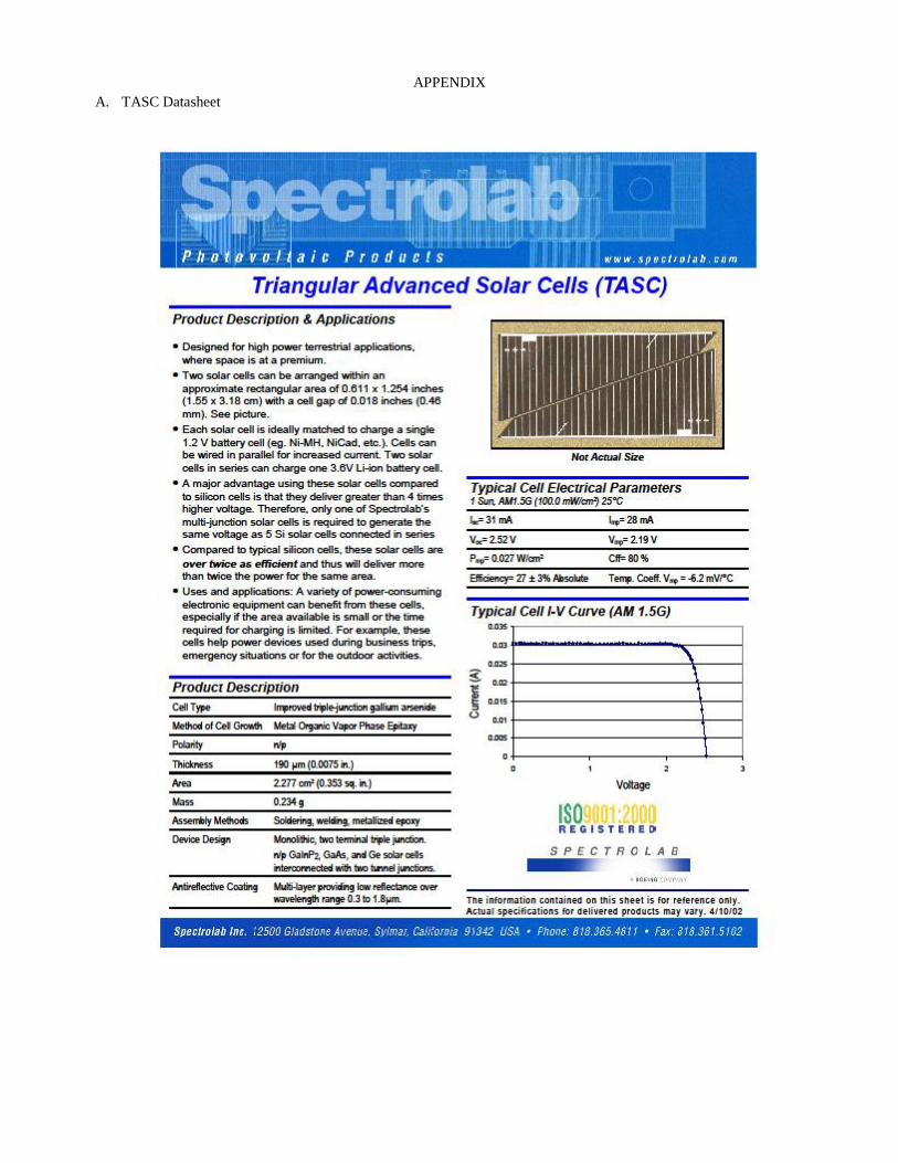
APPENDIX
A. TASC Datasheet

B. EPS datasheet (Relevant Data)
**This datasheet is for the newest version of the Gomspace P31u. The version ordered is an older version and the
datasheet will have to be obtained from Gomspace before testing is done. The only difference is the PV input voltages.
For the test system we will be receiving the marked value is 5.5V.
5.5**


C. Current limiting datasheet (Relevant Information)