intelligent ground vehicle competition igvc - 2017 · intelligent ground vehicle competition igvc -...
TRANSCRIPT

Intelligent Ground Vehicle Competition
IGVC - 2017
Indian Institute of Technology Madras, India
Team Abhiyaan
Faculty Advisor Statement:
I hereby certify that the development of vehicle, Kernel, described in this report has been equivalent to the work involved in a senior design course. This report has been prepared by the students of Team Abhiyaan under my guidance.
Dr.Nitin Chandrachoodan Associate Professor, Department of Electrical Engineering, IIT Madras
Team Members: Muhammedh Ajwahir, Sai Ramana Kiran, Kuldeep Purohit, Karteek Dhara, Abhijeet Ghawade, Mohammed Khandwawala, Siddharth Bhatia, Deepak Kumar, Viswajeet Anand, Favas M, Fakheem, Fariz, Utsav Tank, Atul, Vishnu Raj, Anand Rajasekar, Asit Tarsode, Milind Srivastava, Ajay Joshi, Narendiran CG, Yamini Singh

Contents
1 Introduction 1
2 Team organization and task split 2
3 Innovations in design 2
4 Mechanical Module 34.1 Vehicle Structure . . . . . . . . . . . . . . . . . . . . . . . . . . . . . . . . . . . . . . . 34.2 Modularity . . . . . . . . . . . . . . . . . . . . . . . . . . . . . . . . . . . . . . . . . . 34.3 Robustness . . . . . . . . . . . . . . . . . . . . . . . . . . . . . . . . . . . . . . . . . . 44.4 Changes in the new design . . . . . . . . . . . . . . . . . . . . . . . . . . . . . . . . . . 44.5 Dimensions and specifications . . . . . . . . . . . . . . . . . . . . . . . . . . . . . . . . 4
5 Electrical Module 55.1 Power System . . . . . . . . . . . . . . . . . . . . . . . . . . . . . . . . . . . . . . . . . 55.2 Battery Management System . . . . . . . . . . . . . . . . . . . . . . . . . . . . . . . . 55.3 Wireless control . . . . . . . . . . . . . . . . . . . . . . . . . . . . . . . . . . . . . . . . 55.4 Microcontroller unit . . . . . . . . . . . . . . . . . . . . . . . . . . . . . . . . . . . . . 5
6 Software Module 76.1 Navigation . . . . . . . . . . . . . . . . . . . . . . . . . . . . . . . . . . . . . . . . . . . 76.2 Simlulation . . . . . . . . . . . . . . . . . . . . . . . . . . . . . . . . . . . . . . . . . . 86.3 Computer Vision . . . . . . . . . . . . . . . . . . . . . . . . . . . . . . . . . . . . . . . 8
7 Modes of failure and remedies 9
8 Cost Estimation 11
9 Acknowledgment 11
1 Introduction
The main functionality of this ground vehicle is to perceive the environment, localize itself in it andnavigate outdoor while avoiding obstacles. We take sensor data from various sources and process itinto a form that helps the bot map the environment and localize in it. This data is also processed byspecific nodes to generate a costmap that effectively represents the obstacles in the environment andinflates them to approximately represent the configuration space of the bot.
We currently have the following 5 sensors on our bot:
• LiDAR (Light Detection and Ranging)
• GPS (Global Positioning System)
• IMU (Inertial Measurement Unit)
• Encoders
• Camera
LiDAR is the primary sensor used to detect obstacles. It scans the surroundings in a 2D plane andgives a polar profile that enables one to calculate the position of an obstacle within a certain range.GPS, IMU, Encoders are used for localization of the bot. We have also implemented visual odometryusing a camera. An overview of the architecture can be seen in the flow chart 1.
1

Figure 1: Architecture overview
2 Team organization and task split
The team consists of about 30 enthusiastic undergraduate as well as postgraduate students fromvarious departments. The team is organized into 4 modules - Electrical, Mechanical, Navigation andComputer Vision. Bot Kernel is the second prototype of an autonomously navigating ground vehiclecreated by Team Abhiyaan. The shortcomings of the team during the previous years led to problems inthe mechanical and electrical aspects of the bot. Efforts were made towards correcting these mistakesand to make the bot more robust.
3 Innovations in design
• Modularity: The bot is designed to be modular. It can be disassembled easily by unscrewingthe screws holding the aluminium channels together. All sensors can also be removed easilyfrom the mechanical frame of the bot. The acrylic sheets attached for rainproofing can also besimply unscrewed. This helps in easy transport of the bot.
• Compartmentalization: There are 3 levels of compartmentalization. The lower level hasall the wiring, gears and motors. The middle level holds the circuitry and the BMS (BatteryManagement System). The upper level holds the components necessary for computation suchas NUC and its battery, router as well as the IMU.
• Bumper: Bumpers are fixed onto the bot to protect the lower mechanical frame of the botfrom serious damage. They are made from Fibre Reinforced Plastics(FRP).
• 3-D Printing: We have 3D printed a custom made insulated casing for holding batteries andinsulating PCB. It contains a LiPo bag that will contain any possible explosion and add anotherlevel of modularity that will be useful while disassembling and assembling the bot.
2

Figure 2: Initial Solidworks model of the bot
4 Mechanical Module
Weight and dimensions of payload are main considerations of design. The major factors consideredto choose shape are efficient space use, low CG, stability, maneuverability.
4.1 Vehicle Structure
The vehicle2 can be subdivided into drive train, frame, steering and castor positioning.
1. Drive train:
• Motors in central part
• Drive shaft and motor connected using flange coupling arrangement
• Ball bearings used to connect to frame to avoid friction and bending moments.
2. Frame:
• Made using aluminium extrusions, ensuring easy assembly/disassembly and modularity.These channels are joined using angle brackets at right-angle joints
3. Steering:
• 2 Differential drive motor powered wheels and 1 castor
• Microcontroller controlled motor RPM
• Internal encoders used for precise motor control and odometry calculations
4.2 Modularity
1. Modular system with independent floors, allowing independent operation
2. It came out to be extremely useful when individual changes were to be made in the electrical ormechanical aspect of machine in a short span of time.
3
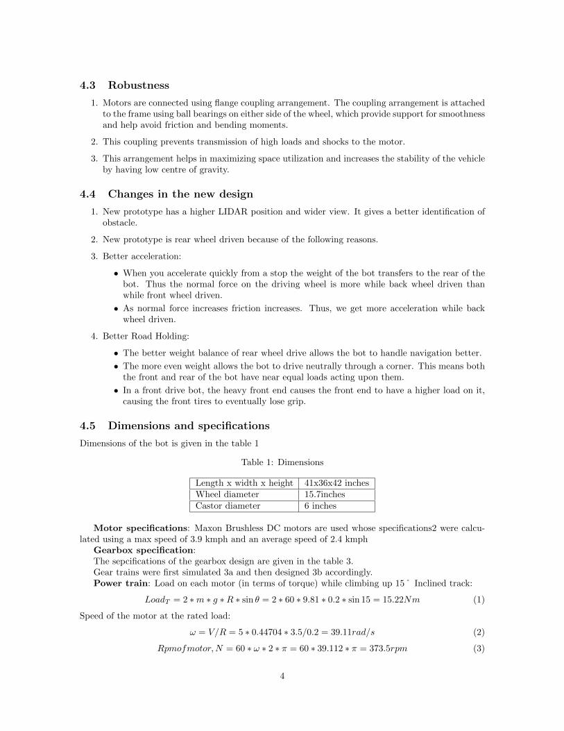
4.3 Robustness
1. Motors are connected using flange coupling arrangement. The coupling arrangement is attachedto the frame using ball bearings on either side of the wheel, which provide support for smoothnessand help avoid friction and bending moments.
2. This coupling prevents transmission of high loads and shocks to the motor.
3. This arrangement helps in maximizing space utilization and increases the stability of the vehicleby having low centre of gravity.
4.4 Changes in the new design
1. New prototype has a higher LIDAR position and wider view. It gives a better identification ofobstacle.
2. New prototype is rear wheel driven because of the following reasons.
3. Better acceleration:
• When you accelerate quickly from a stop the weight of the bot transfers to the rear of thebot. Thus the normal force on the driving wheel is more while back wheel driven thanwhile front wheel driven.
• As normal force increases friction increases. Thus, we get more acceleration while backwheel driven.
4. Better Road Holding:
• The better weight balance of rear wheel drive allows the bot to handle navigation better.
• The more even weight allows the bot to drive neutrally through a corner. This means boththe front and rear of the bot have near equal loads acting upon them.
• In a front drive bot, the heavy front end causes the front end to have a higher load on it,causing the front tires to eventually lose grip.
4.5 Dimensions and specifications
Dimensions of the bot is given in the table 1
Table 1: Dimensions
Length x width x height 41x36x42 inchesWheel diameter 15.7inchesCastor diameter 6 inches
Motor specifications: Maxon Brushless DC motors are used whose specifications2 were calcu-lated using a max speed of 3.9 kmph and an average speed of 2.4 kmph
Gearbox specification:The sepcifications of the gearbox design are given in the table 3.Gear trains were first simulated 3a and then designed 3b accordingly.Power train: Load on each motor (in terms of torque) while climbing up 15˚ Inclined track:
LoadT = 2 ∗m ∗ g ∗R ∗ sin θ = 2 ∗ 60 ∗ 9.81 ∗ 0.2 ∗ sin 15 = 15.22Nm (1)
Speed of the motor at the rated load:
ω = V/R = 5 ∗ 0.44704 ∗ 3.5/0.2 = 39.11rad/s (2)
Rpmofmotor,N = 60 ∗ ω ∗ 2 ∗ π = 60 ∗ 39.112 ∗ π = 373.5rpm (3)
4

Table 2: Motor sepecifications
No load speed 7580 rpmNo load current 15.7inchesStall torque 2280 mNmMax. Efficiency 91%Operating Voltage 24V
Table 3: Gear sepecifications
Type of gear drive Spur gearModule 2 mmPitch diameter of Gear 126 mmPitch diameter of pinion 36 mm%Gear Ratio 3.5Pressure angle 20˚
5 Electrical Module
5.1 Power System
Among all the sensors on the bot, LiDAR, GPS, motors and Intel NUC consume the most power.Owing to their high energy density mainly, the source of power on the bot are Lithium Polymer (LiPo)batteries. The power source comprising of three batteries power the who le bot 4.
5.2 Battery Management System
LiPo batteries are known to have a lot of energy cycles, but only if they are operated safely and withina certain voltage limit. As the battery discharges, its voltage also falls and for a LiPo battery when itsvoltage falls under a certain threshold, it becomes unusable and in some cases even unsafe. In order todeal with this issue our bot is equipped with a battery management circuit, which continuously sampleseach cell’s individual voltage and when any cell’s voltage falls below the threshold it immediatelyswitches over to another battery of the same voltage.
5.3 Wireless control
• The Auxiliary power source is connected through the RF module on the bot. This RF Modulehelps to wirelessly control the circuit by switching it ON/OFF using a remote control. Thisserves as the Wireless E-stop, added to the Mechanical E-stop (Push-button) on the vehicle.
• Wireless Joystick: A wireless joystick has been designed for controlling the bot manually whenit is not on ‘self-driving’ mode. The joystick is an analog 2-axis thumb device. NRF24L01 whichwirelessly transfers the analog value to the bot, which has another transceiver NRF24L01.
5.4 Microcontroller unit
The Arduino Due was preferred as the MCU because of its QEI (Quadrature Encoder Interface). TwoArduino Due are used since any one of them individually cannot handle the encoder counts in themotors. UART serial communication interface is implemented between the 2 Arduinos which act asmaster and slave system to transfer data between them.5
5

(a) Simulated Gear (b) Physical Gear
Figure 3: Gears
Figure 4: Power distribution
6

Figure 5: Main PCB
Since the digital I/O pins in the Arduino can only endure voltage upto 3.3V, there is a risk ofburning the MCU while interfacing with sensors like the wheel encoders. To prevent this, optocouplersare used to step down the voltage signal of the encoder before providing it to the Due.
6 Software Module
We are currently using ROS (Robot Operating System) as the base framework for our bot. At thelowest level, ROS offers a message transmission interface that provides inter-process communication.The whole ROS architecture is divided into nodes that communicate with each other by means oftopics. Nodes can subscribe to topics to access specific information and can publish to topics todisseminate information in the form of messages. The advantage of ROS is that it provides a modularbase to work on, which effectively abstracts out the details of the working of one node from another.This helps in easy debugging.
The software consists of 2 main parts, one that deals with navigation part and the other that dealswith computer vision.
6.1 Navigation
There are 3 main components that comprise the software. These are localization, mapping and pathplanning. We then use simulation to validate the robustness of these algorithms.
• Localization - Proprioceptive sensors used are IMUs and Motor Encoders. Exteroceptive sen-sors used are LiDAR and Camera. Environmental sensor are GPS. Data from proprioceptive andenvironmental sensor are fed into a EKF. The posterior from EKF and data from exteroceptivesensors is used as a prior in particle filter to improve the pose estimate of the robot.6
• Mapping - Occupancy grids are used to map data about environment as perceived by thesensors. Occupancy grids are filled with data from observation sources. Different occupancy grids
7

Figure 6: Localization and Mapping
are made to detect flags, lanes, barrels and they are combined. The resulting occupancy gridis used to create a costmap which approximates the robot configuration space. Obstacles/lanesand flags in the occupancy grid are inflated using a parameter with appropriate costs to createa costmap using data about the obstacles
• Path Planning - We plan paths in the costmap using the Teb Local Planner (Timed ElasticPlanner). This planner exposes lot of parameters that allows one to customize its behaviourto a large extent. This planner also integrates a controller within it that provides commandvelocities that are fed to the motor drivers.
6.2 Simlulation
A robust physics engine is used to evaluate the model the efficiency of the algorithms and theperformance of controller system and sensors. The simulation aids in reducing the stress on thebattery system by limiting the testing of the bot only when it is necessary by acting as a pointof validation. Screenshot of the same are in the fiugre 7
6.3 Computer Vision
We utilize the gradient and color information for lane detection which can then be utilized as abase map for generating a costmap. We use innovative algorithms in computer vision to achievethis task.
To avoid processing the weak edges resulting from the unnecessary texture within the grassregions, we utilize mean-shift filtering which causes edge-preserving smoothing of the image.This preserves and emphasizes the boundaries between the lane and grass regions.
8

(a) LiDAR detecting obstacles in the environment (b) Visualization in RViz
Figure 7: Simulation of bot Kernel in Gazebo
Within the processed image, we detect lanes using a custom algorithm, namely the matched filterwith first-order derivative of the Gaussian (MF-FDOG), as an extension and generalization ofthe MF. It has been successfully applied to nerve segmentation in retinal images. This method iscomputationally efficient with the simplicity of a convolutional operation using gaussian kernelsand its derivatives, but leads to much higher accuracies than edge (or color) thresholding basedmethods. Considering that the cross section of a lane is a symmetric Gaussian function, we usea pair of filters, the zero-mean Gaussian filter (i.e. the MF) and the first-order derivative of theGaussian (FDOG), to detect the vessels. For a true lane, it will have a strong response to theMF around its peak position, while the local mean of its response to the FDOG will be close tozero around the peak position. In contrast, for non-lane structures, for example the step edge,it will have high response to the MF but the local mean of its response to the FDOG will alsobe high. We apply a locally adaptive threshold to the response of matched filter using the localoutput value of FDOG filter.
This method is robust to shadows or uneven lighting conditions and works with lanes of anybackground. The working is shown in the figure 8 in sequence.
7 Modes of failure and remedies
They are tablulated in table 4
We complement this approach with a color based method for image segmentation, namely theGraph-Cut algorithm. It minimizes the sum of a data cost and a smoothness cost calculated overall the pixels in the image. The data-cost is the cost of assigning a particular class label to anypixel based on its color. It decreases if the pixel is more white (lane-like). The smoothness costis the cost of assigning a particular label to a pixel, given the labels assigned to its neighboringpixels. It decreases when all the nearby pixels have the same class label. Proceeding in thisfashion, we obtain color based segmentation for every frame.
We take the intersection of the two results for every frame and align it with Laser-sensor basedcoordinates for path-planning. We then take homographic projection and combine it with thelaserscan. The limitation of this algorithm is that due to high gradients in the grass region ifthey aren’t smoothened properly they might also be detected as lanes.
9

(a) Original Image (b) Mean-shifted Image
(c) Detected lanes
Figure 8: Lane detection using MF-DoG
Table 4: Falure modes and remedies
Failure Modes Resolution/RemedyExcess vibration that may distort sensor data Air filled tyres with pressure that can be
varied accordingly to dampen vibrationsBattery drain BMS will change over to a spare battery
and in worst case stops power supply ifno spare battery charge is left
Battery explosion Insulated casing with LiPo pack to containthe effects of battery explosion
Damage to wires Running wires through grooves in aluminiumextrusions to prevent external factors fromdamaging wires
No data from LiDAR/Overflow of encoder data Stopping the vehicle in such extreme casesFalse detection of lanes Using meanshift algorithm to smoothen
the image to avoid false detection
10

8 Cost Estimation
In the table 5, the second column indicates the cost born by this year’s team. Certain sensorcomponents were already bought by the previous year team.
Table 5: Cost
Components Actual Price (in USD) Cost born by the teamSick LMS1xx 5,000$ 0$Hemisphere a101 3,000$ 0$Sparton IMU 1,500$ 0$Maxon Motors 770$ 770$Escon Motor Drivers 320$ 160$Microcontrollers 190$ 190$Batteries 500$ 500$Miscellaneous Electrical components 160$ 160$Frame and fasteners 300$ 300$Miscellaneous Mechanical components 100$ 100$Acrylic sheets 30$ 30$Total 13,860$ 2,210$
9 Acknowledgment
The team would like to acknowledge IIT Madras for exposing us to such an amazing opportunityto participate in IGVC – 2017. Our faculty advisor, Prof Nitin Chandrachoodan, has alwaysbeen extremely supportive of our project. We would like to thank our seniors and contributorsespecially Prathyusha, Arvind and Ashish who have been a pioneer in this field and guided usin the early stages. We would also like to thank the student body, Center For Innovation (CFI),of IIT Madras which has always stood by us in times of challenges and motivated us.
11