intelligent digital surveillance system - 34telecom video channel user manual.pdf · page 1 of 19...
TRANSCRIPT

Page 1 of 19
Intelligent Digital Surveillance System
User’s Guide
16 Video channel surveillance and recording
eSoft
Version 1.A Revised: 06/01/2003

Page 2 of 19
Table of contents 1. PREFACE..............................................................................................................3
2. ARCHITECTURE...................................................................................................3
3. OPERATION..........................................................................................................3
3.1. SECURITY CONTROL PROGRAM (CONTROL) ........................................................3 3.2. ADMINISTRATION PROGRAM (ADMINISTRATOR) ....................................................3 3.2.1. SYSTEM LOGON ................................................................................................4 3.2.2. MAIN SCREEN OF ADMINISTRATION PROGRAM .....................................................4 3.2.2.1. SYSTEM ADMINISTRATION...............................................................................5 3.2.2.1.1. E-MAIL ......................................................................................................5 3.2.2.1.2. MESSAGE SERVICE ....................................................................................5 3.2.2.1.3. HOLIDAY SETUP .........................................................................................6 3.2.2.1.4. VIDEO RECORDING CAPACITY SETUP...........................................................6 3.2.2.1.5. SYSTEM ALARM SETUP...............................................................................7 3.2.2.1.6. JUMPING SCREENS SETUP..........................................................................9 3.2.2.1.7. SOFTWARE REGISTRATION..........................................................................9 3.2.2.2. USER AND GROUP .......................................................................................10 3.2.2.2.1. USER ......................................................................................................10 3.2.2.2.2. GROUP ...................................................................................................11 3.2.2.3. E-MAP ........................................................................................................12 3.2.2.3.1. ADD AREA ...............................................................................................12 3.2.2.3.2. ADD EQUIPMENT......................................................................................13 3.3. MONITORING PROGRAM (MONITOR)..................................................................16 3.3.1. SYSTEM LOGON ..............................................................................................16 3.3.2. VIDEO SCREEN DISPLAY AREA .........................................................................17 3.3.3. SPLIT SCREENS FUNCTION OPTION AREA .........................................................17 3.3.4. VIDEO CONTROL OPERATION AREA...................................................................18 3.3.5. SYSTEM FUNCTION OPTION AREA.....................................................................19 3.3.6. ALARM REPORT ..............................................................................................19 3.3.7. ALARM E-MAP.................................................................................................19
Page 3 of 19
1. Preface Thank you for purchasing the “Intelligent Full-Function Digital Surveillance System”.
The software supports Windows 2000/XP operating systems. Please read the user’s guide carefully to assure the normal operation of the system.
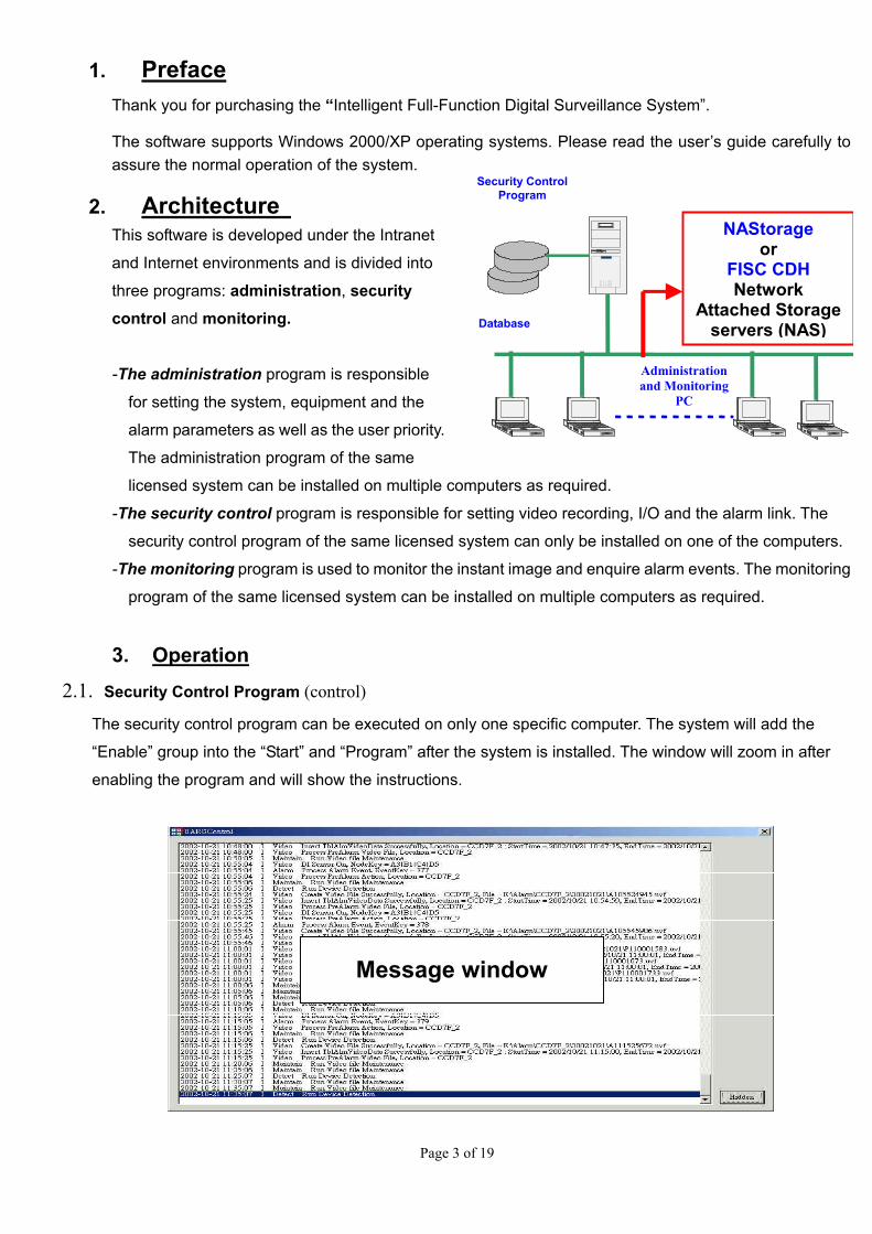
2. Architecture This software is developed under the Intranet
and Internet environments and is divided into
three programs: administration, security control and monitoring. -The administration program is responsible
for setting the system, equipment and the
alarm parameters as well as the user priority.
The administration program of the same
licensed system can be installed on multiple computers as required.
Security Control Program
Administration and Monitoring
PC
NAStorageor
FISC CDH Network
Attached Storage servers (NAS)Database
-The security control program is responsible for setting video recording, I/O and the alarm link. The
security control program of the same licensed system can only be installed on one of the computers.
-The monitoring program is used to monitor the instant image and enquire alarm events. The monitoring
program of the same licensed system can be installed on multiple computers as required.
3. Operation 2.1. Security Control Program (control)
The security control program can be executed on only one specific computer. The system will add the
“Enable” group into the “Start” and “Program” after the system is installed. The window will zoom in after
enabling the program and will show the instructions.
Message window

Page 4 of 19
3.2 Administration Program (Administrator)
The administration program can be executed simultaneously on several computers. Please refer to the System Installation Guide for the standard installation procedure. The detailed operation is described below:
3.2.1. System Logon
Before executing the software, the user must key in a user name and a password to confirm his identity and assure the security use and administration requirements of the system. Please refer to the following for adding a new user name and password: - If you log on onto the system through Internet, please click the “Logon from Internet” option. - If you use three times an incorrect user name or password, the system will automatically stop logging on.
3.2.2. Main screen of the administration program
Tree function area
Function display area
Toolbar

Page 5 of 19
The main screen of the administration program is divided into three (3) main areas: 1. Toolbar : It is the main functional option for the display area. The contents of this toolbar option will vary
according to the option that you select from the tree function area. 2. Tree function area : It mainly includes three major sections:
2.1 System Administration 2.2 User and Group 2.3 e-Map
3. Function display area : It mainly displays the data in the display area while executing the function of the tree function area. It also includes the e-Map display area.
System administration functions The main system administration functions of the software include:
3.2.2.1.1. E-mail
3.2.2.1.2. Message service
Identity of the sender
Server name
User name
Password
Company name

Page 6 of 19
3.2.2.1.3. Holiday setup
It lets users select the national holidays or any special holiday defined by the company in addition to weekends. After selecting these dates and clicking the “Holiday Priority” option, the system will give alert at those holidays.
3.2.2.1.4. Video recording capacity setup
It provides the repeated use of the system storage space in which the video recording storage path will point at your desired path of the storage schedule, video recording and alarm video recording data.

Page 7 of 19
- Capacity Allocation : It represents the maximum capacity of the data storage. - Capacity Alert Point : It represents the data storage capacity and alarms if the stored data exceeds this alert point. - Reserved Capacity : It represents the minimum capacity of the old stored data when repeatedly using the storage space.
Note: If the data flow exceeds the “Capacity Alert Point”, the system will inform the related staff with a specific alarm according to the setup described in “Section 3.2.2.1.5 System Alarm Setup”. If the data flow reaches the “Capacity Allocation” point, the system will automatically delete some of the old data until the data capacity reaches again the “Reserved Capacity” point.
3.2.2.1.5. System alarm setup
It lets the administrator notice any related staff for repair and maintenance work when errors occur in the system. The software provides three main system warning sources :
1. If the hard disk capacity exceeds the alert point (please refer to the “Section 3.2.2.1.4 Video Recording Capacity Setup”).
2. If the network is disconnected. 3. If the database is abnormal and its access remains abnormal when it runs again. The system will alarm such
event as the only source for the abnormality.

Page 8 of 19
For a related warning setup, you can press the “Alarm Action …” button for the setup in the alarm link window. As for the system alarm section, there are two options: “All-time Enable” and “Disable”. The current link provides two ways of noticing the related staff : by e-mail & message. Press the “Add” button to add the link or use any other ready set settings.

Page 9 of 19
3.2.2.1.6. Jumping screens setup
It allows the administrator to select the cameras to display the desired 4/10/13 or16 split screens provided by the software. For each display window, the system will perform the jumping screens according to the specified intervals if more than one camera is selected. You can click the display window and make your selection in the following windows.
3.2.2.1.7. Software registration
Refer to the System Installation Guide for the description of the registration.
Page 10 of 19
3.2.2.2. User and Group
3.2.2.2.1. User
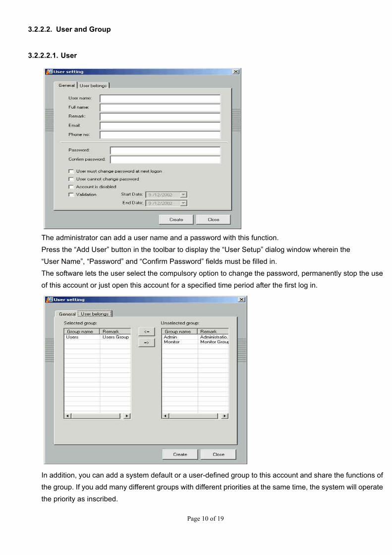
The administrator can add a user name and a password with this function. Press the “Add User” button in the toolbar to display the “User Setup” dialog window wherein the “User Name”, “Password” and “Confirm Password” fields must be filled in. The software lets the user select the compulsory option to change the password, permanently stop the use of this account or just open this account for a specified time period after the first log in.
In addition, you can add a system default or a user-defined group to this account and share the functions of the group. If you add many different groups with different priorities at the same time, the system will operate the priority as inscribed.

Page 11 of 19
3.2.2.2.2. Group
There are two default groups:
1. Administrator : This user has the highest priority to any operation including the functions of adding and deleting equipment and accounts for the control.
2. Monitor : This user has the priority to the operations of viewing images, accessing history data and controlling cameras and does not has the aforementioned administrator priorities .
Note that these two basic groups cannot be deleted.
The administrator can also define the function group according to the requirements of its administration and give the priority of the executable function to such group through the “Function Attributes”.

Page 12 of 19
3.2.2.3. e-Map
It lets the administrator manage the equipment and know the exact location of the event when the alarm is triggered. Details are as follows:
3.2.2.3.1. Add area
Use the “Add Area” button of the toolbar to establish the area node according to the requirements of the administration and click it. The following options will appear in the toolbar:
1. Add Area : Add another area node under this node. 2. Edit Area : Change the area name of this node. 3. Delete Area : Delete this area node (please note that the system will delete all sub-area nodes and
equipments under the node).
4. Upload Background Figure : Add an area figure onto this area node.
The software provides the following formats for the graphic file :
5. Update Background Figure : Since the software will save the related settings in the cache at the end of running the program and, for a better execution performance (if an administrator updates the background figure at the remote end), the administration program at such end will not automatically update the background figure. Therefore, we can use this function to update or logon onto the system immediately.
6. Display Ratio : It sets up the display ratio of the equipment figure and the background figure. 7. Add Network Camera : Please refer to the next section : “Add Equipment”. 8. Add Video Gateway : Please refer to the next section : “Add Equipment”. 9. Add I/O Controller : Please refer to the next section : “Add Equipment”.

Page 13 of 19
3.2.2.3.2. Add equipment
You can add equipment after completing the construction of area nodes. Since the operation for each equipment is very similar, we will take the “Add Video Gateway” as an example.
1. Press the “Add Video Gateway” button. 2. Set the related settings for the hardware and network, including the fields of - IP address -
communication port – brand/ model number - equipment location - the fields of IP address and equipment location cannot be repeated. The system will proceed with the confirmation.
3. After setting up the hardware, the system will automatically add the related figures according to the number
of video channels and GPIOs of the hardware. The equipment name remains blank before you add the camera and sensor. With the mouse you will be enable to place the related cameras at the surveillance locations and give them a code (ex. Stock # 1, Storage # 5, Booth # 3, etc.)

Page 14 of 19
4. Click on the desired camera icon under such video gateway for editing and press the “Edit Camera” button in the toolbar. Now you can set up the related information for such camera including the settings such as : channel number - equipment location and all kinds of video recordings.
The “Image Displacement Detection Video Recording” function is a special displacement detection technology used by the software to compress (reduce) the programmed video recording data.
5. After completing the setup, you can now set up the default video quality or enable the displacement detection function using the buttons : “Displacement Detection Setup” and “Video Quality Adjustment”.
6. Finally, if you enable the displacement detection for the camera, you can set up the alarm using the “Alarm
Link” button. If you click the “Holding Setup”, the alarm will be enabled for the entire day.
7. You can add the link to the alarm using the “Add” button. The linkable operations include: instant alarm image,
e-mail, message transmission, alarm video recording and default video point. You can also use other ready set settings.
Page 15 of 19
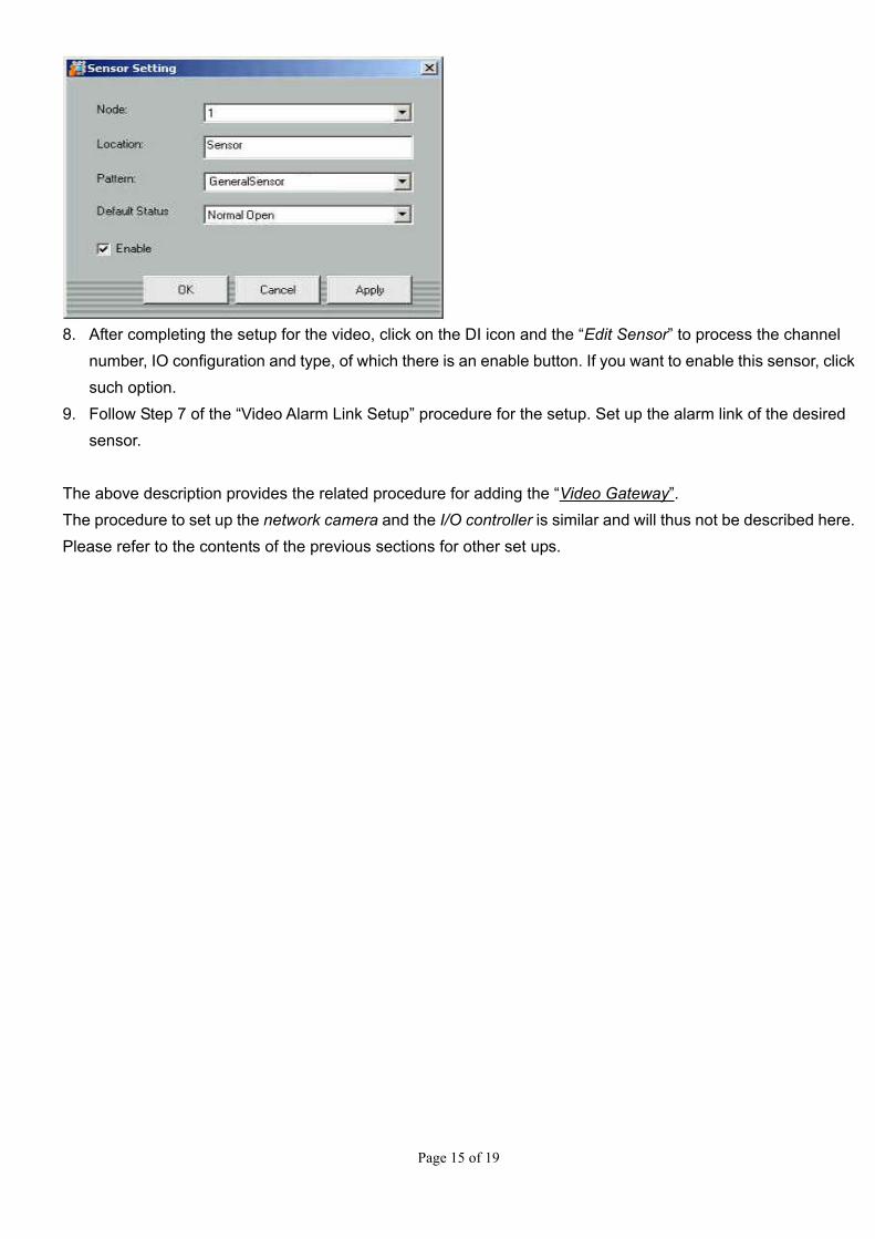
8. After completing the setup for the video, click on the DI icon and the “Edit Sensor” to process the channel
number, IO configuration and type, of which there is an enable button. If you want to enable this sensor, click such option.
9. Follow Step 7 of the “Video Alarm Link Setup” procedure for the setup. Set up the alarm link of the desired sensor.
The above description provides the related procedure for adding the “Video Gateway”. The procedure to set up the network camera and the I/O controller is similar and will thus not be described here. Please refer to the contents of the previous sections for other set ups.

Page 16 of 19
3.3 Monitoring program (monitor)
The monitor (monitoring program) of the software can be executed simultaneously onto several computers. Please refer to the System Installation Guide for the standard installation procedure. The following is the detailed description of the operation.
3.3.1. System log on
Before executing the software the user must key in the user name and password for authentication to assure the secure use of the system and the requirements of the administration. Please refer to the following procedure to add user name and password. If you log onto the system via Internet, please click the “Logon from Internet” option (remember - if you use three times an incorrect user name or password, the system will automatically stop logging on). The main screen of the system is shown below:
Split Screen Function
Option Area
Video Screen Display
Alarm Report
Video Control
Operation Area
Alarm e-Map Area
System Function
Option Area
The main screen of the monitoring program is divided into 6 major areas: 1. Video Screen Display Area 2. Split Screen Function Option Area 3. Video Control Operation Area 4. System Function Option Area 5. Alarm Report
6. Alarm e-Map

Page 17 of 19
3.3.2. Video screen display area
This function area displays the instant split jumping screens or single screen. If you want to control a certain screen of the split screens, click the split windows. The surrounding of such window will show a red frame, and the operation will focus on the split window in the video operation area.
3.3.3. Split screens function option area
: The video screen display area is shown in a 4-split window.
: The video screen display area is shown in a 10-split window.
: The video screen display area is shown in a 13-split window.
: The video screen display area is shown in a 16-split window.
: The video screen display area shows the channel video.
: Enables or disables a specified relay status.
: Stops the instant video display and the jumping screen functions.

Page 18 of 19
3.3.4. Video control operation area
This area carries out the video recording of his machine by a specific selected camera and the PTZ control function for the user.
: Displays the location and name of the specific camera.
: Displays the date and time of that particular image.
: Carries out the instant video recording for the user by his machine.
: Plays the recorded history video file on his machine.
: Selects the directory for saving the video play recorded by his machine.
: Takes a snapshot for the currently displayed instant image, which can be saved as a video
file in the JPEG or Bitmap format.
: Normal size of the displayed image
: Doubles the size of the displayed image
: PTZ Control Area
: Automatic navigation function.
: Stops the automatic navigation function.
: Adjusts the PTZ moving speed.
: Selects the set default location.

Page 19 of 19
3.3.5. System function option area
This area mainly focuses on the main system functions including the following functions: : Play the history data saved in the software
: Enables or disables the alarm function of this machine.
: Enquires about the event and its response. Print out the information of the event and
press the “Exit” button to exit.
3.3.6. Alarm report
When an abnormal event occurs in the system or equipment, the system will automatically show such even in this report. If you want to know more about the link of such event, double click on it to bring out the detailed information and status of the response to the event.
3.3.7. Alarm e-Map
If an equipment link event occurs, this area will automatically show the e-Map for the location of the event. If you click the event in the alarm report, this area will also change accordingly to show the corresponding location of the event in the e-Map. Note: This function is only available for the event generated using the monitoring. The abnormal system event will not be associated with the e-Map alarm link function.