intelligent design & construction guidance document
TRANSCRIPT


INTELLIGENT DESIGN & CONSTRUCTION GUIDANCE DOCUMENT
i
DISCLAIMER
The authors alone are responsible for the preparation and accuracy of the information,
data, analysis, discussions, recommendations, and conclusions presented herein. The contents do
not necessarily reflect the views, opinions, endorsements, or policies of the Utah Department of
Transportation or the U.S. Department of Transportation. The Utah Department of
Transportation makes no representation or warranty of any kind, and assumes no liability
therefore.

INTELLIGENT DESIGN & CONSTRUCTION GUIDANCE DOCUMENT
ii
TECHNICAL REPORT ABSTRACT
1. Report No. UT- 17.04
2. Government Accession No. N/A
3. Recipient's Catalog No. N/A
4. Title and Subtitle INTELLIGENT DESIGN & CONSTRUCTION GUIDANCE
DOCUMENT [DRAFT]
5. Report Date March 2017
6. Performing Organization Code
7. Author(s) George Lukes - UDOT, Jim McDowell - Lochner
8. Performing Organization Report No.
9. Performing Organization Name and Address Utah Department of Transportation Preconstruction Division
P.O. Box 148460
Salt Lake City, UT 84114-8460
10. Work Unit No.
11. Contract or Grant No.
12. Sponsoring Agency Name and Address Utah Division Federal Highway Administration
2520 West 4700 South
Suite 9A
Salt Lake City, UT 84129410
13. Type of Report & Period Covered Final
Feb 2013 to Mar 2017 14. Sponsoring Agency Code
15. Supplementary Notes
Prepared in cooperation with the Utah Department of Transportation and the U.S. Department of
Transportation, Federal Highway Administration
16. Abstract
17. Key Words Intelligent Design and Construction, pilot projects,
3D model, CM/GC, design/bid/build, Bentley,
Trimble
18. Distribution Statement Not restricted. Available through:
UDOT Research Division
4501 South 2700 West
P.O. Box 148410
Salt Lake City, UT 84114-8410
www.udot.utah.gov/go/research
23. Registrant's Seal
N/A
19. Security Classification
(of this report) Unclassified
20. Security Classification (of this page)
Unclassified
21. No. of Pages
61
22. Price N/A

INTELLIGENT DESIGN & CONSTRUCTION GUIDANCE DOCUMENT
iii
TABLE OF CONTENTS
LIST OF FIGURES .............................................................................................................................. vii
LIST OF ACRONYMS ....................................................................................................................... viii
EXECUTIVE SUMMARY .................................................................................................................... 1
1.0 INTRODUCTION ............................................................................................................................ 4
Overview ................................................................................................................................4
Background ............................................................................................................................4
Pilot Projects ..........................................................................................................................7
Outline of Report ...................................................................................................................8
2.0 PILOT PROJECT 1: SR-20, PASSING LANE MP 10 TO MP 12 .................................................. 9
Project Details ........................................................................................................................9
Project Description ................................................................................................................9
Procedures ............................................................................................................................10
2.3.1 Survey .......................................................................................................................... 10
2.3.2 Construction survey ..................................................................................................... 11
2.3.3 Inspection survey ......................................................................................................... 11
2.3.4 Workspace .................................................................................................................... 12
2.3.5 Construction inspection ............................................................................................... 12
2.3.6 As-builts ....................................................................................................................... 12
Use of Models ......................................................................................................................13
Use of Paper Plans ...............................................................................................................14
Benefits of Using IDC .........................................................................................................14
2.6.1 Clearing and grubbing boundaries ............................................................................... 14
2.6.2 Models to surfaces for AMG ....................................................................................... 14
2.6.3 Quick turnaround for design changes .......................................................................... 14
2.6.4 Use of the rover to inspect surfaces ............................................................................. 15
2.6.5 Use of Masterworks ..................................................................................................... 15
2.6.6 Schedule savings .......................................................................................................... 16
Factors Contributing to Success ..........................................................................................16
2.7.1 Selection of straightforward pilot project and CM/GC contracting method ................ 16

INTELLIGENT DESIGN & CONSTRUCTION GUIDANCE DOCUMENT
iv
2.7.2 Selection of a contractor with advanced technical skills ............................................. 16
2.7.3 Flexibility of the design team, support from management, and access to experts ....... 17
2.7.4 Bentley ICM to TBC .................................................................................................... 17
2.7.5 Breaking models down to component models ............................................................. 17
Lessons Learned ..................................................................................................................18
2.8.1 Methods are needed to accept inspected surfaces with the rover ................................ 18
2.8.2 Survey completeness is essential ................................................................................. 18
2.8.3 More detailed guidance is needed for topographical surveys ...................................... 18
2.8.4 UDOT inspection personnel were able to play a more active role .............................. 19
2.8.5 Masterworks streamlined the inspectors’ roles ............................................................ 19
3.0 PILOT PROJECT 2: SR-10, US-6 TO RIDGE ROAD CM/GC PHASE I .................................... 20
Project Details ......................................................................................................................20
Project Description ..............................................................................................................20
Procedures ............................................................................................................................21
3.3.1 Survey .......................................................................................................................... 21
3.3.2 Workspace .................................................................................................................... 21
3.3.3 Construction inspection (scheduled summer 2018) ..................................................... 22
3.3.4 As-builts ....................................................................................................................... 22
Use of Models ......................................................................................................................22
Use of Paper Plans ...............................................................................................................24
Model Review and QA/QC ..................................................................................................24
Takeaways ...........................................................................................................................24
3.7.1 Workspace ................................................................................................................... 24
3.7.2 IDC methods and workflows ....................................................................................... 25
3.7.3 Knowledge transition ................................................................................................... 25
4.0 PILOT PROJECT ANALYSIS ...................................................................................................... 26
Software ...............................................................................................................................26
Workspace ..........................................................................................................................29
Workflows ...........................................................................................................................31
Models and Plan Quantities .................................................................................................32
Preconstruction Survey ........................................................................................................32

INTELLIGENT DESIGN & CONSTRUCTION GUIDANCE DOCUMENT
v
Terrain Survey .....................................................................................................................33
Models .................................................................................................................................34
5.0 CONSIDERATIONS ...................................................................................................................... 36
D/B/B Contracting ...............................................................................................................36
As-Built Drawings ...............................................................................................................37
UPlan ...................................................................................................................................38
Knowledge Preservation and Education ..............................................................................38
Advancement and Discovery ...............................................................................................39
Agency Adoption .................................................................................................................40
6.0 RECOMMENDATIONS AND NEXT STEPS .............................................................................. 41
Pilot Project Delivery ...........................................................................................................41
6.1.1 CM/GC project: Advertise project with model/preconstruction package as the legal
document using CM/GC to develop and refine method with increasing complexity 41
D/B/B Project: Advertise Project with Model/Preconstruction Package as the Legal
Document ...........................................................................................................................41
Preconstruction Survey ........................................................................................................42
6.3.1 Develop guidance for how and when to perform the initial survey control, when to
contract for the survey, and how to define it according to the Geomatics manual ... 42
6.3.2 Develop recommendations for when a point cloud is needed, how designers need to
receive that information, and how/when to get a survey contract executed to keep
design schedules on time .......................................................................................... 42
6.3.3 Develop language for the Geomatics manual to more rigorously define collection
methods for hardscape and softscape surveys .......................................................... 42
6.3.4 Develop a method that enables contractor survey crews to verify and accept the
preconstruction survey .............................................................................................. 42
Preconstruction/Design ........................................................................................................43
6.4.1 Develop model surfaces such that granular borrow, untreated base course, and
asphalt/Portland cement can be paid as plan quantities ............................................ 43
6.4.2 Develop and refine method for associating metadata with model features ................. 43
6.4.3 Develop method for generating workspace modifications required for IDC............... 43
6.4.4 Implement UDOT IDC workspace based on OpenRoads SS4 .................................... 43

INTELLIGENT DESIGN & CONSTRUCTION GUIDANCE DOCUMENT
vi
6.4.5 Develop OpenRoads CONNECT workspace .............................................................. 44
6.4.6 Develop OpenRoads CONNECT Workflows ............................................................. 44
6.4.7 Develop guidance on how to use Quantity Manager ................................................... 44
6.4.8 Develop guidance on how to deliver models for the most efficient consumption by
contractors and their subcontractors ......................................................................... 44
6.4.9 Develop guidance on QC/QA and review of preconstruction package/model ............ 45
6.4.10 Develop guidance on ICM generation and best practices .......................................... 45
6.4.11 Develop guidance on how to package models for advertisement with digital
signatures .................................................................................................................. 45
6.4.12 Develop method through which contractors can receive and comment on model and
ultimately agree to accept it as legal document ........................................................ 46
Construction/Inspection .......................................................................................................46
6.5.1 Develop and explore alternate methods for viewing CADD and GIS data in the field 46
6.5.2 Develop/provide guidance for field crews on how to document various surface
measurements ............................................................................................................ 46
6.5.3 Document when plan sheets are used (summaries, details, typicals)........................... 47
6.5.4 Accommodate model usage cases ................................................................................ 48
6.5.5 Develop guidance and contract language for specification of as-builts by contractor 48
6.5.6 Develop language to define the as-built deliverables with enough detail to provide the
agency with maximum flexibility and utility ............................................................ 49
7.0 CONCLUSION ............................................................................................................................... 50
REFERENCES ..................................................................................................................................... 52
GLOSSARY ......................................................................................................................................... 53

INTELLIGENT DESIGN & CONSTRUCTION GUIDANCE DOCUMENT
vii
LIST OF FIGURES
Figure 1: Automated Machine Guidance Concrete Paver in Action ...............................................5
Figure 2: SR-20 Finished Project .....................................................................................................9
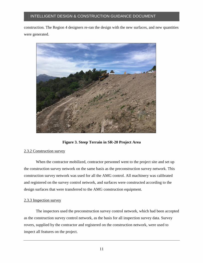
Figure 3. Steep Terrain in SR-20 Project Area ..............................................................................11
Figure 4: SR-10 Project Existing Conditions.................................................................................20
Figure 5: SR-10 Project Model ......................................................................................................23

INTELLIGENT DESIGN & CONSTRUCTION GUIDANCE DOCUMENT
viii
LIST OF ACRONYMS
2D two-dimensional
3D three-dimensional
4D four-dimensional
AMG automated machine guidance
ATMS advanced traffic management systems
CADD computer-aided drafting and design
CM/GC construction manager/general contractor
D/B/B design/bid/build
DOT Department of Transportation
FHWA Federal Highway Administration
FIO for information only
GIS geographic information systems
GPS Global Positioning System
ICM Integrated Consensus Model
IDC Intelligent Design and Construction
MOT maintenance of traffic
ORN OpenRoads Navigator
PDBS Project Development Business System
PDF Portable Document Format
PIH plan-in-hand
QA/QC quality assurance/quality control
SR State Route
TBC Trimble Business Center
UAV unmanned aerial vehicle
UDOT Utah Department of Transportation
WiFi wireless fidelity

INTELLIGENT DESIGN & CONSTRUCTION GUIDANCE DOCUMENT
1
EXECUTIVE SUMMARY
In 2013, the Utah Department of Transportation (UDOT) began investigating methods,
branded as Intelligent Design and Construction (IDC), that would better take advantage of the
efficiencies afforded by advances in highway design software, construction methods, and
automated machine guidance (AMG). In January 2014, UDOT visited the Iowa Department of
Transportation to learn from its experience delivering electronic plan sets as part of its
construction deliverables. UDOT also conferred with the Federal Highway Administration
(FHWA) about its experience and guidance related to the use of 3D models for construction.
In April 2014, UDOT formally kicked off its IDC effort by hosting the FHWA 3D
Engineered Models for Construction Workshop. A broad range of experts from the Association
of General Contractors, the American Council of Engineering Companies, software vendors, and
UDOT technical staff and management participated in the FHWA workshop and in follow-up
meetings and workshops. These meetings led to the publishing of short-term and midrange plans
for the implementation of 3D models for construction. These plans included
The identification of key team members and management commitments to provide
resources for the development of IDC.
A strategy to use construction manager/general contractor (CM/GC) contracting on a
series of increasingly complex pilot projects to develop IDC capabilities.
A goal to deliver the model as the contract document on CM/GC and
design/bid/build (D/B/B) projects.
The first two successful pilot projects were the SR-20, Passing Lane MP 10 to MP 12,
and SR-10, US-6 to Ridge Road, CM/GC Phase I projects. These projects developed and
validated many IDC methods and workflows.
The SR-20, Passing Lane MP 10 to MP 12, IDC pilot project was designed by UDOT
Region 4 and constructed during the 2016 construction season. Several significant advancements
came from the SR-20 project. Most significantly, the project demonstrated the ability to deliver

INTELLIGENT DESIGN & CONSTRUCTION GUIDANCE DOCUMENT
2
3D models as the contract document in lieu of paper plans and the ability of contractors to
construct the project on the basis of those models—something that had never been achieved by
any other state department of transportation. As a result of the milestones that were achieved and
the technology and methods that were developed and validated, the SR-20 project was named the
2016 UDOT Innovative Project of the Year.
Major accomplishments on the SR-20 project included
Awarding the model as the legal document and providing plan sheets for information
only.
Validating the need for a high-quality construction survey during preconstruction.
Demonstrating the feasibility of delivering 3D design surfaces for use in AMG.
Developing methods for displaying design models on mobile devices for construction
and inspection.
Validating a method for the use of 3D design surfaces to inspect constructed surfaces
using the survey rover.
Illustrating the amount of plan production time that could be reduced or eliminated
by producing more detailed models.
Demonstrating the value of tight integration between the design and construction
software vendors and the design team and their consultant partners.
Building on the success of SR-20 and the efforts underway on the SR-10 pilot project,
additional pilot projects are being conducted with the goal of delivering 3D models as the
contract document on a D/B/B project. From the lessons learned in the initial pilot projects and
to satisfy the goals established in the IDC plans, the I-80 Climbing Lanes project in Region 2
(construction 2018, CM/GC), SR-68 in Region 2 (construction 2017, CM/GC), the I-70
rubblization/rehabilitation project in Region 4 (construction 2017, D/B/B), Bangerter Highway to
12600 South urban widening, I-15 climbing lanes MP 20 in Region 4, and the SR-193 greenfield

INTELLIGENT DESIGN & CONSTRUCTION GUIDANCE DOCUMENT
3
connector highway project in Region 1 (construction 2017, D/B/B) are currently being conducted
as IDC pilot projects. The goals for these projects include the advancement and refinement of the
technology and methods that have already been demonstrated on the SR-20 and SR-10 pilot
projects and the extension of IDC methods to D/B/B.

INTELLIGENT DESIGN & CONSTRUCTION GUIDANCE DOCUMENT
4
1.0 INTRODUCTION
Overview
In 2016, the Utah Department of Transportation (UDOT) received State Transportation
Innovation Council funding from the Federal Highway Administration (FHWA) to document the
processes and decisions resulting from the ongoing effort to deliver 3D models as the contract
document on highway construction projects. On a pilot project, UDOT became the first
department of transportation (DOT) in the nation to achieve this goal. This documentation is
intended to catalog the existing efforts and serve as an internal roadmap for the continued
development and ongoing refinement of Intelligent Design and Construction (IDC) methods for
producing and delivering 3D models for construction. With advances in technology opening up
possibilities to streamline the design and construction of projects, UDOT has embraced this
technology, with the ultimate goal of delivering projects in a more accurate, safe, efficient, and
cost-effective manner.
Background
Over the past 25 years, roadway modeling software has evolved from primitive packages
that could generate tables of earthwork quantities to sophisticated tools that can create an exact
virtual 3D replica of the proposed design. Agencies have taken advantage of some of the new
modeling features to create realistic visualizations for public involvement and education efforts,
but the majority of the modeling capabilities have been underutilized. For many years, UDOT
has used modeling software for visualizations on sensitive design projects, such as the Legacy
Parkway, and on projects that require driver education, such as the continuous flow intersection
on Bangerter and the diverging diamond interchange at Pioneer Crossing. However, for standard
design projects, modeling has been limited to that required to produce and deliver 2D paper
construction plans—the standard deliverable on highway construction projects.
Over the same period, contractors have adopted technology that enables them to be more
accurate and more efficient in delivering projects. Contractors have adopted construction-
specific modeling software to transform the paper plans delivered by transportation departments

INTELLIGENT DESIGN & CONSTRUCTION GUIDANCE DOCUMENT
5
into 3D models. Contractors use these models in estimating quantities, designing construction
phasing plans, designing maintenance-of-traffic (MOT) plans, surveying, and guiding
construction equipment with automated machine guidance (AMG).
Figure 1: Automated Machine Guidance Concrete Paver in Action
With engineers creating 3D models for design and contractors using 3D models for
construction, it is logical that engineers could supply contractors with 3D design models. This,

INTELLIGENT DESIGN & CONSTRUCTION GUIDANCE DOCUMENT
6
however, has not been the case. The traditional design deliverable, used in all 50 states, entails
engineers creating 3D models and then reducing those models to a series of 2D views that can be
printed as paper plans and delivered as part of the engineering bid package. The contractor then
takes the 2D plans and reverse engineers them to create 3D digital models that are used in
construction. It is estimated that as much as 50 percent of the time spent designing a project is
used to produce 2D paper plans, and contractors invest significant time and resources turning the
2D paper plans back into 3D models.
In recognition of these inefficiencies and recent advances in technology, UDOT has
piloted a series of projects under the umbrella of IDC. The goal with these projects is to develop
the technology, methods, and workflows necessary to eliminate 2D plan sheets and replace them
with the design and delivery of the 3D model as the contract document. This piloting effort is an
attempt to advance a project-lifetime data model that will eliminate the current inefficiencies of
the designer using design modeling software to design in 3D and then convert to 2D paper plans
for bid purposes, followed by the contractor using construction modeling software to convert the
plans back to 3D models for construction. The IDC approach seeks to leverage the benefits of
highly detailed digital models that are directly consumable by contractors and can also be
retained by the agency as a high-fidelity representation of the constructed reality or as-built
condition.
Prior to 2014, some contractors had obtained digital files directly from designers, but
starting in 2014, UDOT began formally supplying digital surfaces and other design files, along
with paper plan sheets, as part of the deliverable package. On the initial projects, the digital
models were supplied for information only (FIO). Contractor feedback was positive; many
contractors reported that obtaining the model files provided a valuable check against the models
they were creating from the paper plans.
This delivery of FIO digital models complemented the guidance provided by FHWA in
its April 2014 3D Engineered Models for Construction Workshop conducted at UDOT. A
handful of state agencies across the country had reported the potential for more accurate
earthwork computations, earlier detection and resolution of clashes, faster collaborative decision
making, more efficient bid preparation, and the ability to use models for surveying and AMG

INTELLIGENT DESIGN & CONSTRUCTION GUIDANCE DOCUMENT
7
during construction. After the workshop, UDOT formulated a plan to explore and evaluate the
benefits and risks of adopting IDC methods.
Beginning in summer 2014, UDOT hosted a series of workshops to identify and mitigate
the risks associated with delivering models as the legal document. The participants included
UDOT management and staff, design consultants, members of the American Council of
Engineering Companies, contractors from the Association of General Contractors, and software
suppliers, including Bentley and Autodesk. In these workshops, a dialog was opened between
contractors, UDOT, and technical experts about what would serve the agency and the design and
construction community best for delivering 3D models instead of 2D plans. These collaborative
efforts identified many of the risks and benefits that would likely result from moving toward a
more model-driven design deliverable and served as the foundation for the goals set forth in the
UDOT IDC short- and midterm plans published in 2014 and 2015 (1, 2).
Concurrently with the risk and mitigation workshops, UDOT decided to move forward
with a pilot program to develop IDC methods and workflows. UDOT Central and UDOT Region
4 proposed using construction manager/general contractor (CM/GC) contracting, in recognition
that developing the model as the legal document required input and concurrence from the
designers and the contractor. CM/GC allowed the contractor to provide feedback and specifics
on exactly what types of models they could use and gave the design team the opportunity to
understand the specifics of how contractors integrated models into their construction processes.
Pilot projects were selected in a way that allowed IDC to be developed on uncomplicated
projects initially and then implemented in more complicated projects as the methods and
workflows became established.
Pilot Projects
As outlined in the 3D Engineered Models for Construction Implementation Plan (3), four
projects—SR-68 in Region 3, I-15 Farr West to Brigham in Region 1, SR-20 in Region 4, and I-
215 in Region 2—were identified to develop and refine the UDOT design team’s OpenRoads
modeling capabilities and the IDC methods. Due to circumstances including project delays due
to funding and software implementation issues, the projects’ usefulness for developing IDC

INTELLIGENT DESIGN & CONSTRUCTION GUIDANCE DOCUMENT
8
methods and workflows was limited, except for the SR-20 project. The lessons learned from
these projects mostly centered on the importance of having specific features available in the
software and time available in the schedule to devise workarounds, as required, to overcome
software limitations.
The first two IDC pilot projects that were able to utilize OpenRoads SS4, a version that
included updates that remedied some of the problems encountered on the early projects, were the
SR-20, Passing Lanes MP 10 to MP 12, and SR-10, US-6 to Ridge Road, CM/GC Phase I
projects in UDOT Region 4. Both were selected due to their relative simplicity of design and
limited number of design disciplines (roadway, drainage, signing, striping, and right-of-way).
During the risk workshops, it was determined that candidate pilot projects should be as
straightforward as possible so that time could be focused on developing the IDC workflows and
methods instead of solving complex design challenges.
Outline of Report
This report details the progress made and lessons learned on the two Region 4 pilot
projects, discusses considerations for future IDC pilot projects, and recommends next steps in
IDC implementation. The report is structured as follows:
Introduction
Pilot Project 1
Pilot Project 2
Pilot Project Analysis
Considerations
Recommendations and Next Steps
Conclusion

INTELLIGENT DESIGN & CONSTRUCTION GUIDANCE DOCUMENT
9
2.0 PILOT PROJECT 1: SR-20, PASSING LANE MP 10 TO MP 12
Project Details
Project PIN: 11430
Project Number: F-0020(10)10
Contracting Method: CM/GC
Designers: UDOT Region 4
Inspection: UDOT
Status: Constructed summer 2016
Figure 2: SR-20 Finished Project
Project Description
The SR-20 pilot in UDOT Region 4 was a project to add climbing lanes to SR-20
between mileposts 10 and 12 on the side of a mountain with steep slopes above the road and
long, heavily vegetated fill slopes below.

INTELLIGENT DESIGN & CONSTRUCTION GUIDANCE DOCUMENT
10
UDOT’s goal was to award the model as the legal document. SR-20 was chosen due to its
lack of design complexity, the limited number of design disciplines, and the resulting reduction
in risk associated with those elements. To further increase the likelihood of success, CM/GC
delivery was used to allow collaboration between the contractor and the design team during the
production of the 3D model package as the legal document. The SR-20 project successfully
delivered the model as the legal document and won the UDOT 2016 Innovative Project of the
Year award.
Procedures
2.3.1 Survey
The initial survey control network was established by UDOT’s survey consultant per the
2015 UDOT Survey & Geomatics Standards (4). A 1-cm geodetic survey was completed, and
level loops were run through all the network control points.
The initial terrain survey was conducted by the same UDOT consultant using
(static/terrestrial) lidar. After CM/GC contractor selection, UDOT was made aware by the
contractor that the slope surveys on portions of the project were inaccurate and could not be
relied on for quantities. Due to the density and type of vegetation, much of the lidar coverage
outside of the roadway prism was determined to be insufficient; lidar returns captured the tops of
the vegetation and not the existing ground. To remedy this situation, the UDOT survey
consultant collected supplemental survey points. Per the Geomatics manual, side slope data was
collected via cross sectioning, using a Global Positioning System (GPS) rover, and added to the
points generated from lidar. The survey data was compiled and incorporated into the existing
ground model.
On award of the project, the contractor performed a spot survey to validate the existing
ground model. After the additional survey points were compared with the UDOT existing ground
model, it was determined that more survey points were needed on the steep, heavily vegetated
slopes to account for the grade breaks between cross sections. Additional points were collected
and merged with all the previous survey data, and a new surface was generated for use in
INTELLIGENT DESIGN & CONSTRUCTION GUIDANCE DOCUMENT
11
construction. The Region 4 designers re-ran the design with the new surfaces, and new quantities
were generated.
Figure 3. Steep Terrain in SR-20 Project Area
2.3.2 Construction survey
When the contractor mobilized, contractor personnel went to the project site and set up
the construction survey network on the same basis as the preconstruction survey network. This
construction survey network was used for all the AMG control. All machinery was calibrated
and registered on the survey control network, and surfaces were constructed according to the
design surfaces that were transferred to the AMG construction equipment.
2.3.3 Inspection survey
The inspectors used the preconstruction survey control network, which had been accepted
as the construction survey control network, as the basis for all inspection survey data. Survey
rovers, supplied by the contractor and registered on the construction network, were used to
inspect all features on the project.

INTELLIGENT DESIGN & CONSTRUCTION GUIDANCE DOCUMENT
12
2.3.4 Workspace
The workspace used on the SR-20 project was the production version of the UDOT
ProjectWise workspace developed to support OpenRoads SS4. No feature definitions or item
types developed specifically for IDC were incorporated into the workspace.
2.3.5 Construction inspection
For the inspection of the graded surfaces, the UDOT designers supplied the UDOT
inspectors with design surfaces that were loaded into the survey rover. The survey rover was
supplied by the contractor and tied in to the construction survey network but was operated by
UDOT inspection personnel.
The surface information in the rover allowed inspectors to compare the elevation of
points on the ground with the corresponding points on the theoretical design surface. This
allowed the inspectors to directly inspect the graded surfaces and provide real-time feedback on
whether the construction surfaces met the design intent. The inspection points collected by the
inspectors were supplied to the design team for use as a quality check and in daily log
documentation using Masterworks software.
The inspection team reported that using Aurigo Masterworks greatly reduced the time
spent creating the daily diary. Without Masterworks, to get a photo into the system, inspectors
took the photo on a phone, emailed it, put it in a Word document, printed the Word document to
Portable Document Format (PDF), and then put the PDF in ProjectWise and sent out the link.
With Masterworks, inspectors were able to snap photos from their iPads and, as soon as they
connected via WiFi, the data automatically synchronized. This method greatly simplified the
inspection process and reduced the delays associated with getting inspection information into the
UDOT system. In addition to this efficiency, daily reports were available to all field crews
immediately, which substantially reduced the administrative time compared to previous projects.
2.3.6 As-builts
In efforts that are underway as of January 2017, as-builts are being created by combining
lidar scans with elevation data derived from photos collected by unmanned aerial vehicles

INTELLIGENT DESIGN & CONSTRUCTION GUIDANCE DOCUMENT
13
(UAVs). In addition, UDOT is testing the ability to transfer feature data to geographic
information systems (GIS) using Safe FME software.
Use of Models
The effective use of models evolved over the 12 months of design and construction.
When the project design started, the software documentation suggested that it was possible to
publish Bentley design models in an Integrated Consensus Model (ICM) format that could be
converted 1:1 to a Trimble Business Center (TBC) model for use by the contractor. However, the
UDOT Region 4 designers and the contractor discovered that the conversion utility did not work
correctly and could not be used. As a result, UDOT Central began a series of biweekly calls with
Bentley and Trimble to coordinate the successful fix of the software.
While the software was being fixed, UDOT Region 4 designers and the contractor
devised a workaround to allow the exchange and comparison of the design and construction
models and achieve model consensus. The workaround involved UDOT supplying the native file
formats (.dgn, .alg, .dtm, and LandXML) to the contractor. The contractor then used Autodesk
Civil3D to convert those files into components used to build the contractor’s TBC models. This
workaround was cumbersome since it introduced time and complexity between when the model
was supplied by the designers and when it was available for comparison by the contractor. This
lag between the design model being supplied and the construction model being available for
feedback resulted in models being passed back and forth for many months to achieve model
consensus.
During construction, the Bentley-to-Trimble, ICM-to-TBC conversion utility was fixed
and made available to the team. Although it is anticipated that the ICM will streamline the effort
required to generate and pass surfaces to the contractor, its use on SR-20 was limited due to its
late arrival. Instead, the native files were awarded as the legal document.

INTELLIGENT DESIGN & CONSTRUCTION GUIDANCE DOCUMENT
14
Use of Paper Plans
For some construction activities, paper plans that were supplied FIO were used to
construct and inspect the SR-20 project. The paper plans were utilized or referred to by
inspectors approximately 15 to 20 percent of the time at the beginning of construction. As the
construction engineering team became more familiar with Bentley OpenRoads Navigator (ORN)
and after additional leader notes were added to the models displayed on the inspectors’ mobile
tablets, reliance on paper plans diminished. The contractor also used ORN extensively as the
project progressed.
Benefits of Using IDC
The use of models instead of paper plans resulted in several significant benefits on the
project, as outlined in this section.
2.6.1 Clearing and grubbing boundaries
Through the use of iModels of the project boundaries loaded onto ORN, the contractor
was able to set rough clearing and grubbing boundaries prior to the construction survey network
being established. This process resulted in the contractor being able to start clearing and
grubbing immediately and shaved several days off the overall schedule.
2.6.2 Models to surfaces for AMG
Designers supplied design surfaces in a format that could be converted to AMG. This
process saved time compared with the traditional method of the contractor building surfaces
from paper plans and ensured that the design surface and construction surface were identical.
2.6.3 Quick turnaround for design changes
When it was discovered that supplemental survey data was needed, UDOT Region 4
design personnel were able to receive the data from the contractor, reprocess that data into a new
surface, and supply the data back to the contractor in less than a day. Since construction staking

INTELLIGENT DESIGN & CONSTRUCTION GUIDANCE DOCUMENT
15
was unnecessary, the contractor implemented the changes in its AMG equipment and proceeded
with construction without lengthy delays. This process resulted in significant schedule savings.
2.6.4 Use of the rover to inspect surfaces
UDOT inspectors used the surfaces supplied by the UDOT Region 4 designers to inspect
the constructed surfaces. The designer-supplied surfaces were loaded onto the contractor-
supplied rover, which was tied in to the construction survey network. The inspectors then used
the surface model in the rover to randomly check any point on the finished surface against the
UDOT design surface. The rover display showed inspectors the numerical difference between
the field shot and the model value. If the two points were within tolerance, the screen showed the
difference in green. Out-of-tolerance values were shown in red. This tool allowed the inspectors
to quickly determine if points on the graded surface were within the construction tolerance of the
design surfaces and enabled valuable communication between the UDOT construction crews and
the contractor on rough-graded surfaces.
In one case, by comparing the design surface to the graded surface using the rover,
inspectors found a significant out-of-tolerance condition. When the errors were traced to their
source, it was determined that the AMG equipment had experienced blade wear, which caused
surfaces to be graded too high. The contractor noted that the equipment had not checked in with
the control network on a regular enough schedule, which allowed the error to propagate. Once
the equipment began checking in regularly and the blade wear was accounted for, the regraded
surfaces were reinspected and found to be within tolerance. This entire episode validated the
method for checking surfaces against the theoretical design surface and demonstrated the
necessity of having all AMG equipment check in with the control network on a frequent (daily)
basis.
2.6.5Use of Masterworks
Logging the daily diary using Masterworks resulted in a significant reduction in the effort
required by inspectors to log and document inspection data. This reduced the workload
associated with keeping the daily diary and allowed more time for inspectors to be actively and
constructively involved in the project.

INTELLIGENT DESIGN & CONSTRUCTION GUIDANCE DOCUMENT
16
2.6.6 Schedule savings
The original construction schedule for the project was estimated as 90 days. In large part
due to the time savings outlined in the above sections, the project was completed approximately
23 days ahead of schedule. Much of this saving was credited to the use of IDC methods.
Factors Contributing to Success
Prior to the SR-20 pilot project, very few methods and workflows existed to guide the
process. In many cases, the functionality that was needed in the software did not exist, and
workarounds were necessary. This required flexibility from the designers and support from the
software manufacturers and outside experts. Several key factors and decisions positively
influenced the outcome, and those decisions are detailed in this section.
2.7.1 Selection of straightforward pilot project and CM/GC contracting method
The careful screening of the project before its selection as a pilot project helped make it
successful. The limited number of disciplines and the comparative simplicity of design enabled
the team to effectively allocate resources and develop the workflows and methods necessary to
deliver the model as the contract document. The use of CM/GC contracting allowed for an
iterative design and model delivery process, which was essential for developing the IDC
workflows. The discussions between the contractor and Region 4 designers enabled the project
team to fully develop methods and workflows that would not have been possible on a D/B/B
project.
2.7.2 Selection of a contractor with advanced technical skills
The development of IDC methods benefited from having a contractor that had advanced
technical knowledge of modern construction methods and possessed Bentley OpenRoads
software skills on par with the designers. The ability for the contractor to directly incorporate the
Bentley legacy file formats (.alg, .dgn, .dtm) and convert them to TBC using ACAD Civil3D,
when necessary, greatly contributed to the success of the project.

INTELLIGENT DESIGN & CONSTRUCTION GUIDANCE DOCUMENT
17
2.7.3 Flexibility of the design team, support from management, and access to experts
Since there was no published information on how to approach and conduct an IDC
project, it was vital to have a skilled and flexible design team, supported by management, with
direct access to the software manufacturers, technical consultants, and the contractor’s technical
experts. A major portion of the project involved discovering and devising workflows and
methods that were necessary to overcome software bugs and the lack of existing software
functionality. Involving experts, having management support, and being able to adapt and
change directions allowed the team to overcome major roadblocks that otherwise would have
resulted in the abandonment of IDC methods and reversion to traditional methods to deliver the
project.
2.7.4 Bentley ICM to TBC
Early attempts to use the Bentley-to-TBC workflow for ICMs were unsuccessful. At the
behest of UDOT, Bentley and Trimble engaged in cooperative calls with UDOT and the
contractor to solve the problem. Due to time constraints, a workaround was devised to pass
model data to the contractor using legacy file formats, but by the end of the project, the project
ICM was validated to match the project TBC model developed by the contractor. This validation
is a very promising step toward advertising D/B/B projects with the model as the legal document.
2.7.5 Breaking models down to component models
In response to problems encountered when trying to use comprehensive ICMs and
iModels, it was decided to simplify the workflows and break large models down into component
models. Live nesting caused problems with model generation, and software limitations
associated with saved views made large, comprehensive models impractical. Therefore, the IDC
team devised methods to break comprehensive models into simplified component models for
consumption by the contractor.

INTELLIGENT DESIGN & CONSTRUCTION GUIDANCE DOCUMENT
18
Lessons Learned
Several important lessons were learned during this pilot project, and those lessons are
outlined in this section.
2.8.1 Methods are needed to accept inspected surfaces with the rover
The SR-20 UDOT inspectors were able to inspect the built surfaces using the design
model loaded into the rover, but the inspectors identified the need for guidance on inspecting,
accepting, and documenting surfaces. Normal construction methods often rely on constructing
and inspecting only a portion of a given surface during a certain phase of construction.
Inspection methods are needed to reconcile the realities of piecemeal surface construction.
Dividing surfaces into lots that could be inspected and accepted has been suggested as a
possibility, as has the use of point-to-reference model surface comparison reports generated by
the rover. These possibilities will be tested on future pilot projects.
2.8.2 Survey completeness is essential
Construction based on the model is only as accurate as the survey on which the model is
based. Although the roadway terrain survey was very good, discrepancies existed between the
existing conditions survey on the side slopes and the augmented slope survey that was collected
after clearing and grubbing had concluded. To reduce quantity errors in construction, the design
needs to be based on the same survey that the contractor uses for construction and surfaces need
to be collected at sufficient density, detail, and accuracy to generate a realistic representation of
the actual natural ground surface.
2.8.3 More detailed guidance is needed for topographical surveys
On SR-20 there were steep side slopes with considerable vegetation and topographic
variation. Because of the vegetation and long slopes, lidar was not effective at collecting accurate
slope contours. Supplemental survey points that were collected using a rover also proved to be
insufficient due to the difficult and varied nature of the slope and the method used to collect the
data (cross sectioning). On the basis of this experience, UDOT noted that more detailed survey
INTELLIGENT DESIGN & CONSTRUCTION GUIDANCE DOCUMENT
19
collection guidance in the Geomatics manual was needed to support the point density and detail
needed for the IDC methods.
2.8.4 UDOT inspection personnel were able to play a more active role
Inspectors noted that using the rover to inspect surfaces was empowering. The inspectors
became active participants in the construction of the project and were able to provide valuable
real-time feedback. Inspectors who worked on SR-20 indicated that they were enthusiastic to
work on future IDC projects.
2.8.5 Masterworks streamlined the inspectors’ roles
The ability to maintain the daily diary in a time-efficient manner greatly simplified a
process that sometimes causes delays on projects. Although not a direct byproduct of the IDC
process, the ability to efficiently maintain the daily diary helped inspectors keep up with the
faster-paced IDC project.

INTELLIGENT DESIGN & CONSTRUCTION GUIDANCE DOCUMENT
20
3.0 PILOT PROJECT 2: SR-10, US-6 TO RIDGE ROAD CM/GC PHASE I
Project Details
Project Number: F-0010(75)66
Project Pin: 13664
Contracting Method: CM/GC
Designers: Consultants
Inspection: UDOT
Status: Scheduled for construction summer 2018
Project Description
SR-10 is a rural widening project that will add a center turn lane, curb and gutter, and
draining improvements over sections of the roadway and make changes to the vertical alignment
to improve safety
.
Figure 4: SR-10 Project Existing Conditions

INTELLIGENT DESIGN & CONSTRUCTION GUIDANCE DOCUMENT
21
Procedures
3.3.1 Survey
The initial geodetic control survey was performed by UDOT per the 2015 UDOT Survey
& Geomatics Standards (4). A survey consultant performed a GNSS 1-cm survey to densify the
control network where necessary and provide coverage over the entire project limits. Vertical
control was obtained through differential digital leveling. The topographical survey was
collected with lidar, augmented with rover shots in locations where lidar coverage was occluded
by vegetation or otherwise impractical.
The surveyor processed the point cloud data into surfaces and features. Existing features
such as signs, power poles, power lines, striping, drainage features, and road features were
classified and modeled by the surveyor.
3.3.2 Workspace
On the basis of the experience gained from the SR-20 project and familiarity with other
agencies’ implementation of OpenRoads, the UDOT computer-assisted drafting and design
(CADD) workspace for SR-10 was modified to better facilitate the development of IDC methods
and workflows. In coordination with the UDOT staff responsible for the CADD workspace and
with Bentley, several workspace features and workflows were tested and implemented. Those
features and workflows are defined in broad terms as follows:
Changes were made to provide the granularity to control, display, and export models
produced by OpenRoads. Workspace changes were made to add levels, items, and
feature types and create templates that could automatically generate surfaces that
could be directly consumed by the contractor.
Changes were made to creating a top view in the 3D models similar to a roll plot; the
changes included annotation and the ability to display colored model elements in
grayscale, similar to a paper plan set.

INTELLIGENT DESIGN & CONSTRUCTION GUIDANCE DOCUMENT
22
Changes were made to set up 2D and 3D files for proper display in Bentley’s ORN.
The CADD ProjectWise workspace that was developed for SR-10 was delivered to
UDOT and installed on the UDOT ProjectWise system for use on the I-80 Climbing Lanes IDC
pilot project that is currently (January 2017) underway (construction summer 2018).
3.3.3 Construction inspection (scheduled summer 2018)
The plan for inspection is similar to the plan used on SR-20. Inspectors will use a rover
supplied by the contractor to compare constructed surfaces to the design surfaces. The subgrade
surface will be exported by the designers to a format that can be fed directly into the survey rover
being operated by the inspection team, which will eliminate the need for the contractor to convert
the surfaces before using them.
Inspectors will also rely on the annotated scroll plot iModels displayed in ORN on iPads
to view design data. PDF copies of the views from the models will also be supplied as a
reference, similar to what was used for the plan-in-hand (PIH) review (see Use of Models
section).
3.3.4 As-builts
A strategy for collecting as-built data will be developed after the results of the SR-20 as-
built effort have been evaluated.
Use of Models
The design workflow for the SR-10 design effort was fully modified to take advantage of
capabilities that became available on August 1, 2016, in the 08.09.11.872 version of the Bentley
OpenRoads software. Individual component models for roadway, drainage, removals, and
signing and striping were created for the PIH review. These component models were tailored for
display in ORN on mobile tablets. A similar set of models will be included in the project
deliverable package for use in the field for construction and inspection. The consultant is
working with Bentley to provide additional functionality in ORN to enable the display of station,

INTELLIGENT DESIGN & CONSTRUCTION GUIDANCE DOCUMENT
23
elevation, and offset from named geometry, along with a host of other features. This
functionality will greatly enhance the usability of models in the field on mobile devices.
Surface meshes that can be directly exported to the contractor’s modeling platform
(TBC) will be supplied in ICM and LandXML format. These models will be used by the
contractor to program the AMG earthwork equipment and by field technicians to inspect the
surfaces.
Additionally, models tailored to appear like a scroll plot were created for the PIH review
and will be created for the final submittal. PDF versions of these models are being used as part of
the PIH review and will be used by construction and inspection personnel to orient themselves in
the field in lieu of paper plans.
Figure 5: SR-10 Project Model

INTELLIGENT DESIGN & CONSTRUCTION GUIDANCE DOCUMENT
24
Use of Paper Plans
Content that would traditionally be included in paper plans will be provided in 3D models
that have been symbolized with familiar plan set symbols and locked into a viewing orientation
that is similar to a scroll plot. PDF copies of the scroll plot views will also be linked and
packaged with the models for printing and markup as required. Cross sections, details, standard
drawings, and specifications will be available as linked content that can be viewed on a mobile
device in the field using ORN.
Model Review and QA/QC
For PIH review, iModels annotated as scroll plots and PDF views are being supplied to
the reviewers as part of a Bluebeam PDF Studio Session. Bluebeam Studio is a collaborative
software feature that allows invited reviewers to simultaneously open and comment on or mark
up PDF documents in real time. Bluebeam Studio was hosted by the consultant, and the free
version of Bluebeam Revu was installed at UDOT and configured so that comments from all
reviewers were collected in a single review document for preservation as the quality
assurance/quality control (QA/QC) record. The model will be reviewed and compared using
Autodesk Navisworks and Bentley Navigator. After the PIH review is complete, the
effectiveness of the review method will be evaluated and adjusted as necessary. It is anticipated
that the plans, specifications, and estimate review will be conducted in a similar fashion.
Takeaways
Some of the takeaways from the SR-10 project will be carried forward into future pilot
IDC pilot projects. The key takeaways are outlined in this section.
3.7.1 Workspace
A preliminary version of the SR-10 modified UDOT IDC workspace has been supplied to
UDOT for use on the I-80 IDC pilot project. UDOT will incorporate the elements that align with
overall agency goals and install the workspace for use on future pilot projects. A method for

INTELLIGENT DESIGN & CONSTRUCTION GUIDANCE DOCUMENT
25
creating additional item types and feature definitions will be supplied, and any training materials
that are needed will be identified.
3.7.2 IDC methods and workflows
Designers are developing methods to create, symbolize, and display models on iPads that
will look similar to paper plan sheets. The designer is working directly with Bentley to improve
ORN by adding functionality to track named geometry and display station offset and elevation,
along with improvements to ORN’s ability to use saved views.
3.7.3 Knowledge transition
Consultant design staff from the SR-10 project are assisting the UDOT Region 2 design
staff on the I-80 Climbing Lanes IDC pilot project, which commenced in October 2016. The
consultant will assist the staff get up to speed on the methods and workflows necessary for IDC.

INTELLIGENT DESIGN & CONSTRUCTION GUIDANCE DOCUMENT
26
4.0 PILOT PROJECT ANALYSIS
The SR-20 and SR-10 pilot projects had different timelines for completion, and thus
many components of the technology and understanding were at different points in their evolution
at the equivalent point in design. Some approaches, problems, and solutions were the same;
others relied on later software releases and process advancements that were not available for the
earlier project.
Software
For 3D models to be an effective means of delivering a project, data from many sources
must be packaged and included in the model. As-built drawings, survey data, pay item
information, standard drawings, specifications, GIS data, and a host of other data are used to
create a plan set for the advertised deliverable. For models to be the advertised deliverable, the
same information must be included in the model.
Project data is produced, stored, translated, and consumed in many software packages
and systems that are produced by different vendors or developed by UDOT. Some of the
software is natively compatible, but most is not. Therefore, some form of translation, often
requiring manual steps, is required.
Currently, these are the packages that produce or integrate the data used to produce,
deliver, and transmit the project deliverable:
Bentley MicroStation: CADD platform for producing and packaging data into sheets
or models. For paper plans, MicroStation is the tool used to properly construct
drawing features and align and display the annotation necessary to transmit the
design intent.
Bentley InRoads/OpenRoads: the latest version of Bentley InRoads is called
OpenRoads (current version: SS4). OpenRoads is used to produce all highway
geometry (horizontal and vertical alignments), along with all the surfaces and models

INTELLIGENT DESIGN & CONSTRUCTION GUIDANCE DOCUMENT
27
used in the design. OpenRoads runs inside of MicroStation and has become more
integrated with MicroStation with every major release.
Bentley ProjectWise: a work-sharing platform that stores and provides access to the
engineering content on a project. Engineers, designers, and drafters conduct all their
MicroStation and InRoads design work on the ProjectWise platform. The design files
for every UDOT design project ultimately reside in ProjectWise.
Bentley ORN: an application that runs on iOS, Android, and Windows and that is
designed to display and mark up drawings, documents, and models.
UDOT Electronic Project Management: a system that offers UDOT employees, local
government customers, and consultants access to electronic program management.
This system provides information on the planning, funding, scheduling, and staffing
of UDOT design projects.
UDOT Project Development Business System (PDBS): a highway construction
management tool and database. It was developed by UDOT to help facilitate and
electronically document the advertising, bidding/awarding, and construction
activities of all federal, state, and local government projects.
UPlan/GIS: a customized GIS platform capable of serving fully attributed, web-
accessible 2D maps that have been published to the UPlan ArcGIS website. UPlan
currently hosts asset, maintenance, pavement, planning, project, reference, and traffic
and safety data. The complete list can be found in the Open Data Guide (5).
Due to the pioneering nature of the IDC process, many of the features needed to
successfully design models that can be directly consumed in the field by contractors are lacking
or underdeveloped in the current software. This lack of fully implemented functionality greatly
impacted both pilot projects. Not only was some functionality missing from the software, but
some functionality was not refined or did not work as advertised.

INTELLIGENT DESIGN & CONSTRUCTION GUIDANCE DOCUMENT
28
The SR-10 and SR-20 project teams both experienced software bugs and other issues
during design, model production, and publishing that complicated or hindered final project
delivery. Some of these challenges were addressed with workflow modifications or by
compromising on the form and function of the final output; others relied on temporary fixes or
the use of paper plans.
On the SR-20 project, the UDOT Region 4 design team worked directly with Bentley and
Trimble, the software providers, to resolve software issues. On the SR-10 project, UDOT and the
design consultant are working directly with the Bentley developers to help steer the development
process to get the necessary functionality added to the software. To support the UDOT IDC
efforts, Bentley has hired a senior product manager to be the liaison between UDOT, its design
consultants, and the Bentley developers. The product manager has an extensive background in
OpenRoads use and has already supplied some beneficial information on how to streamline some
of the UDOT workflows.
In a dynamic, rapidly evolving process, this type of high-level support will continue to be
essential in sorting through the various software problems to keep the design teams moving and
make sure that the necessary functionality is included in future software releases.
Issues that have been fixed in the software itself are not discussed further, as they are
now obsolete. However, the important lesson for any design team is that it is imperative to have
the latest release of the CADD platform and the civil vertical applications (i.e., OpenRoads)
installed, along with the latest CADD workspace, before commencing with any IDC project.
Software continues to change, and new functionalities are introduced with each new
release. In particular, there have been many improvements in publishing models to mobile
devices for display in the field in lieu of paper plans. Having an advanced understanding of the
software is essential, and staying current on the latest software changes is important.

INTELLIGENT DESIGN & CONSTRUCTION GUIDANCE DOCUMENT
29
Workspace
Modern CADD software is extremely powerful, complex, flexible, and configurable.
There are thousands of setting combinations and many resource files that define things such as
levels, feature definitions, seed files, line styles, text, and almost every other aspect of software
behavior. Together, these settings and files are referred to as the workspace. How the CADD and
ProjectWise staff configure these files and resources has a significant impact on the performance
of the CADD applications and the overall ease of use for the end users.
Different workspaces were used for the SR-10 and SR-20 pilot projects. SR-20 was
hosted on the UDOT ProjectWise server with the UDOT SS4 managed workspace installed.
During SR-20 design development, a few minor modifications to the workspace were made, but
the majority of the workspace remained stock UDOT SS4. Not having a workspace modified for
IDC created problems for the SR-20 design team. As a result, the team had to devise complex
workspace workarounds since the scope, budget, and time to develop the workspace were not
available on the project.
One of the SR-10 pilot project goals was to develop a UDOT SS4 workspace with the
customizations necessary to support the workflows required for IDC. The workspace and project
were hosted on a consultant ProjectWise system, with the idea that many settings and workspace
components would need modification. In addition, the SR-10 project team had the benefit of
starting after the SR-20 project team had uncovered many of the software and workspace issues
and benefited from running later versions of all the software packages.
Not all software currently has the
functionality required for IDC.
IDC designers must use the most recent
applications, platforms, and workspaces.
Advanced and up-to-date understanding of
the software is essential.
IN SUMMARY…
3D models must contain the same data as a
traditional plan set.
This data is stored in many different
software packages; not all are compatible
with each other.

INTELLIGENT DESIGN & CONSTRUCTION GUIDANCE DOCUMENT
30
To implement the changes to the UDOT SS4 workspace, UDOT engaged internal staff
with expertise in workspace configuration and the OpenRoads products, in particular. Using best
practices and approaches that have been proven in other OpenRoads early adopter states, like
Florida, UDOT created and deployed a modified version of the current UDOT workspace,
customized to accommodate 3D model production, display, and delivery. Throughout the
project, refinements and modifications to the workspace will continue to be made to
accommodate the IDC process and project needs.
One of the most significant workspace changes was the addition of feature definitions
and item types for specific disciplines to enable model elements to be tagged with attributes. This
modification was important because it added intelligence to features and could be published or
exported as part of the model.
Pay item information from PDBS was used to tag the corresponding OpenRoads model
elements on the SR-10 project, which allowed them to be published to iModels and therefore
viewed in the field on iPads or other mobile devices. Infusing the workspace with information
from PDBS that will carry all the way through to construction, as-builts, asset management, and
the final data repository is a goal that is being tested and will be refined on SR-10 and future IDC
pilot projects.
UDOT is currently (January 2017) installing the workspace developed on SR-10 for use
on the I-80 IDC pilot project. The scope of the SR-10 workspace was specific to the disciplines
involved in the SR-10 project. Prior to commencing any pilot project, it is important for project
teams to understand the workspace modifications that will be needed to support the project and
have a mechanism in place to produce the necessary modifications. Currently, features and item
Before each pilot project, the team must
determine what workspace modifications
will be needed to support the project.
All modifications should be coordinated with
UDOT Design and Standards.
IN SUMMARY…
CADD workspaces are almost endlessly
customizable.
The UDOT SS4 workspace has now been
modified to support IDC workflows. More
modifications will be necessary as the
workflows become more developed.

INTELLIGENT DESIGN & CONSTRUCTION GUIDANCE DOCUMENT
31
types are being added as needed for the disciplines that are involved with the pilot projects. At
some point, if resources merit, a comprehensive workspace modification to add all PDBS pay
items to the feature and item type libraries may be warranted. Coordination with UDOT Design
and Standards is essential so that all added information is consistent with UDOT standards and
can be added to the main UDOT workspace as required.
Workflows
The order of operations necessary to produce a desired outcome is referred to as a
workflow. For IDC, workflows cover everything from setting up models, assigning features and
item types, breaking models into component models, publishing models to iModel format,
creating iModels that can be published as ICM models for conversion to AMG, and every other
nuanced set of steps for producing models. A properly configured workspace presents the user
with all the configurations, settings, and tools to produce a design, but the order of operations
and methods—the workflow—is vital for producing the desired results. Educating users on
workspace and workflow best practices is important.
A best practices library in ProjectWise is being maintained with documents and links to
videos and other content necessary to produce models for IDC. The current content has been
produced by UDOT and consultants, and the plan is to continue developing and refining the best
practices as required. New software functionality and capabilities greatly influence design
practices and workflows, and maintaining a current set of best practices has been identified as a
key step for advancing the IDC methods from one project to the next.
An IDC best practices library is being
maintained in ProjectWise.
Maintaining and updating these practices
will be a key factor in the successful
advancement of the IDC program.
IN SUMMARY…
The IDC workflow—the order of operations
and methods—is essential in producing the
desired results.
IDC teams must be well versed in workspace
and workflow best practices.

INTELLIGENT DESIGN & CONSTRUCTION GUIDANCE DOCUMENT
32
Models and Plan Quantities
In general terms, quantities are the difference between the existing conditions at the
beginning of a project and the as-built condition at the end of the project. Removals, earthwork,
paving, and the construction of designed features are all elements that are quantified and paid for
on a project. Earthwork and paving are the two quantities that influence contractor bids the most,
and historically, earthwork accounts for the majority of cost overruns on UDOT projects.
Therefore, the IDC team has adopted the goal of minimizing the errors associated with earthwork
and pavement quantities to better manage budgets and reduce the number and size of cost
overruns.
In rough terms, earthwork is the measured difference between the existing subgrade and
natural ground at the beginning of the project and the constructed subgrade at the end. If the
design and construction are based on a common survey and the design models and construction
models are the same, the plan quantities and the construction quantities should be the same.
Preconstruction Survey
In the earliest workshops and pilot project meetings, contractors emphasized that the first
thing they did on a project was check the survey. Discrepancies are viewed as risks, and
contractors noted that they are generally risk averse and account for risk by pricing it into the
bid. If a sawcut line, where new construction will be tied to existing conditions, is discrepant,
contractors adjust their quantities and bid accordingly. The same occurs for any differences noted
in the existing ground survey. If contractors find discrepancies in the existing ground survey,
they adjust their earthwork quantities and bids. Contractors noted that they never relied on the
By enabling design and construction to be
based on the same survey and models, IDC
should greatly minimize errors in these two
quantities and should therefore reduce
costs and overruns.
IN SUMMARY…
Earthwork and paving are the two quantities
that most influence contractor bids.
Earthwork is a major cause of project
overruns.

INTELLIGENT DESIGN & CONSTRUCTION GUIDANCE DOCUMENT
33
preconstruction survey and, instead, resurveyed every project prior to estimating, bidding, or
building.
In recognition that designing on the basis of the preconstruction survey and building on
the basis of a separate construction survey inherently introduces errors into the quantities, the
IDC team set goals for the pilot projects to develop methods and workflows to achieve a single
set of control and terrain surveys that could be used for preconstruction and construction.
Multiple contractors noted that they used more rigorous standards and methods for their
construction control survey than were used for the preconstruction survey. In response to that
feedback, changes were made in the 2015 Geomatics manual to how the preconstruction control
survey should be conducted. Along with the changes, it was noted that a better way to inspect,
verify, and document the preconstruction survey was needed so that contractors could easily
validate the sufficiency of the preconstruction survey. Therefore, goals have also been added to
the pilot projects to satisfy this requirement.
On the SR-10 and SR-20 projects, the survey control network was set up per the revised
Geomatics manual. Supplemental survey was added to densify the grid and extend the control to
the limits of the project. On both projects, the contractor was satisfied that the preconstruction
control network was sufficient for construction. No errors were noted, and no additional control
work was needed on either survey.
Terrain Survey
Lidar scanning augmented with traditional methods was used to collect the existing
ground survey on both pilot projects. On the SR-20 project, dense vegetation and steep slopes
An IDC goal was to develop more rigorous
protocols that would enable the contractor
to rely on the preconstruction survey.
The more rigorous survey was accepted by
the contractor as sufficient on both pilot
projects.
IN SUMMARY…
Contractors always resurvey before bidding.
Discrepancies between the UDOT and
contractor preconstruction surveys are
viewed by the contractor as risk, and that
risk is priced into the bid.

INTELLIGENT DESIGN & CONSTRUCTION GUIDANCE DOCUMENT
34
caused problems with the accuracy of the existing ground survey. Although the surveyor
followed the methods in the Geomatics manual for collecting cross section shots on the slopes,
the variation in the natural ground was more extreme than was captured by the survey. As a
result, areas of the survey were insufficient.
The IDC team noted that changes were needed in the Geomatics manual to help prevent
such situations, in which the survey was collected per the manual but was not sufficient to
represent the true contours of the existing ground. Therefore, IDC goals have been added to
explore options for collecting sufficient existing ground data on projects with steep, heavily
vegetated side slopes and to revise or amend the Geomatics manual as required.
On the SR-10 project, lidar data was collected and augmented with ground shots.
Because of the gentler nature of the terrain and the less dense vegetation, the lidar and
supplemental shots appear to be sufficient to accurately detail the existing ground. The CM/GC
contractor has not noted any deficiencies with the survey, but the final analysis of the survey
adequacy will not be available until construction commences.
Models
Throughout the SR-20 project, the UDOT Region 4 design team supplied models to the
contractor using native Bentley files (.alg, .dtm, and .dgn). The contractor had the technical
expertise necessary to properly open the files in OpenRoads and generate the surfaces needed in
TBC for use in surveys and AMG. Supplying the contractor with the raw design files was
necessary, since at the beginning of the project there was no other means of generating a format
On the SR-10 project, lidar and
supplemental shots have likely been
sufficient to detail the existing ground.
IN SUMMARY…
On the SR-20 project, dense vegetation and
steep slopes affected the accuracy of the
existing ground survey.
The Geomatics manual needs to be updated
to account for such locations.

INTELLIGENT DESIGN & CONSTRUCTION GUIDANCE DOCUMENT
35
that could be directly converted to TBC format. Instead, the contractor used the native Bentley
files and Autodesk Civil3D software to convert the files to the required formats.
By the end of the SR-20 project, the software and workflows were developed enough to
use ICM models to exchange surface data. However, by this point, surfaces had already been
constructed on the project. Although the designers and contractor did not use the method to
exchange live data, the team was able to use the method as a quality check to validate the surface
data that had been exchanged in the native file format. The team recommended that the ICM-to-
TBC method should be added to the best practices documents for further testing and use on
future pilot projects.
The designer and contractor did use the
method for QC.
The ICM-to-TCB method should be added to
the IDC best practices library.
The method will be used on future pilot
projects.
IN SUMMARY…
Workarounds were needed on the SR-20
project while the software was modified to
enable ICM-to-TCB conversion.
The modifications were not completed in
time for the designer and contractor to
exchange live data.

INTELLIGENT DESIGN & CONSTRUCTION GUIDANCE DOCUMENT
36
5.0 CONSIDERATIONS
D/B/B Contracting
CM/GC contracting was used on the early pilot projects since it afforded the opportunity
for collaboration between the contractor and the designer on the survey and design models prior
to award and construction. Both the contractor and the designers were able to provide feedback
and make iterative adjustments as required. The intent of the collaboration was to reduce the risk
of network control, terrain surveys, and models being rejected by the contractor at award.
The challenge of translating IDC methods to D/B/B contracting is the lack of opportunity
for iterative refinement of the survey and design between the contractor and the designers. When
the project is delivered for advertisement, the survey and design have to be final. Any mistakes
in the design models or discrepancies in the survey identified by the contractor will be priced
into the resulting bids. This makes it critical for the preconstruction survey to be complete and
accurate enough to be used for construction.
Through the pilot projects, UDOT is investigating ways to ensure that survey accuracy is
achieved. Details and guidelines for a standardized survey compliance report have been
developed for the Geomatics manual. Along with the standardized report and improved guidance
on how to conduct the preconstruction survey, the possibility of using a third party to verify the
survey is being considered. The ultimate goal is to ensure that the survey matches the ground, the
construction matches the model, the construction quantities match the design quantities, and all
parties agree to be bound by the model as the legal document.
An accurate preconstruction survey, on
which all else is based, is therefore vital.
IN SUMMARY…
The lack of collaboration between the
design and contractor before advertisement
is a challenge for the implementation of IDC
in D/B/B projects.
Any errors in the model or survey will be
priced into the bid as risk.
INTELLIGENT DESIGN & CONSTRUCTION GUIDANCE DOCUMENT
37
As-Built Drawings
After a project is built, as-built drawings are generally marked up by the contractor and
delivered to UDOT, where they are stored in ProjectWise with the original design drawings. For
a model-based system, the desirable outcome is for the design models to be updated with the as-
built data so that the as-built conditions can be stored and displayed. The disposition of as-builts
has been identified as one of the goals for the upcoming pilot projects. Major points of emphasis
will be the methods for collecting the as-built data and for displaying that data in a readily
accessible way.
Fundamental to the as-built discussion is the question of what the as-built condition is. If
a project is built to specifications and meets all the inspection criteria, one possibility is to allow
the design model along with the “as inspected” data to represent the as-built conditions.
Someone accessing the as-built would be presented with the 3D design model and a listing or
report showing the actual values for the inspected models. If packaged in an accessible way, this
approach may serve the needs for as-built deliverables.
Another option is to scan the finished project using lidar or another survey method and
use the scanned points to create surface meshes representing the true as-built dimensions. This
approach might supply more accurate data, but future pilot projects will need to weigh the
theoretical accuracy of a scanned solution against the utility of keeping the model in a true model
format. If a section of roadway is a quarter-inch higher than the theoretical profile, it needs to be
determined if there is any added benefit to using the actual scanned surface represented by
irregular triangles as opposed to theoretical flat surfaces with annotations that it is a quarter-inch
high in specific locations.

INTELLIGENT DESIGN & CONSTRUCTION GUIDANCE DOCUMENT
38
The ultimate solution may involve combining both methods into the deliverable.
UPlan
As part of the SR-20 and I-80 pilot projects, UDOT GIS specialists are investigating tools
and software that would allow attributed model data from OpenRoads to be converted to GIS
data for display on UPlan, along with the inverse operation of supplying GIS data and converting
it to OpenRoads model data. If this two-way conversion is possible, it may allow UPlan and GIS
to play an expanded role in the storage and display of project data, including as-builts. Although
GIS data lacks civil geometry information, which provides the ability to query station, offset, and
elevation data from models, richly attributed GIS data may be useful to augment the project data
used by construction teams in the field, similar to what has been done with utility data currently
in UPlan.
Knowledge Preservation and Education
A central repository is needed for the current best practices, lessons learned, and
institutional knowledge. Resources have been expended, and a large effort has been made to
Another approach would be to scan the
finished project and use the scanned points
to create surface meshes of the true as-built
dimensions.
The second approach would be more
accurate but would sacrifice the true model
format.
IN SUMMARY…
Methods of collecting and displaying as-built
data are a focus of upcoming pilot projects.
One approach would be to store “as
inspected” data with the design model as a
report.
If the two-way conversion is possible, UPlan
and GIS could play an expanded role in the
storage and display of project data.
IN SUMMARY…
UDOT GIS specialists are investigating ways
of converting OpenRoads model data to GIS
and vice versa.

INTELLIGENT DESIGN & CONSTRUCTION GUIDANCE DOCUMENT
39
develop and test the IDC workflows and methods. It is important that this knowledge be
leveraged by future participants in the IDC process.
Some of the elements that are needed include a repository of live training materials that
can be kept up to date with current best practice. The materials need to be a curated so that stale
data is removed and new material is promoted. Since the technology is rapidly changing and new
capabilities are constantly added to existing software, methods and workflows need to be
maintained and evaluated after every major software release. Additionally, as new functionality
and possibilities are discovered in existing or future software, workflows and methods need to be
updated. The development of IDC will continue to be a very fluid process until the technology
stabilizes and the methods prove out.
Additionally, a design process map that details the IDC process needs to be created and
maintained. As with the training materials, this design process map will need to be maintained as
a live document.
Advancement and Discovery
More pilot projects and workshops are needed to explore and understand the technology
and methods necessary for IDC. As technology and software become accessible, UDOT will
All information in the repository should be
regularly updated as software improves and
IDC workflows are modified.
The materials should be curated to ensure
that old versions are archived and new
versions are accessible.
IN SUMMARY…
Preservation of the knowledge gained
through the pilot projects is vital to
successful IDC implementation.
The educational repository should include
live training materials and a design process
map.
UDOT needs to continually evaluate new or
upgraded technology and assess its
potential to improve IDC delivery.
IN SUMMARY…
IDC should continue to be explored through
additional pilot projects and workshops.

INTELLIGENT DESIGN & CONSTRUCTION GUIDANCE DOCUMENT
40
need to evaluate the capabilities and impacts that are made possible. Competing software
solutions and new ways to integrate existing software solutions will continue to propel the
process. The agency needs to stay abreast of current technology and evaluate new technology
that would help streamline IDC project delivery.
Agency Adoption
As the IDC process evolves, what is possible from a technology standpoint will have to
be evaluated against all the other requirements and responsibilities that UDOT is governed by.
IDC has a broad scope that will benefit from evaluation by every department in the agency.
Current workflows as far upstream as environmental studies may someday help to influence the
IDC process and benefit from the results. As models become more standardized and more data
becomes integrated into the models, the method for accessing, viewing, and evaluating project
data will likely change. As deliverables for projects and by projects are redefined, the agency
will have to continue to be responsive to stay abreast of changes.
IDC delivery must continually be evaluated
against all the requirements and regulations
that UDOT is governed by and be modified
as these requirements change.
IN SUMMARY…
IDC has the potential for use by many UDOT
departments. Input from these departments
would be highly beneficial.

INTELLIGENT DESIGN & CONSTRUCTION GUIDANCE DOCUMENT
41
6.0 RECOMMENDATIONS AND NEXT STEPS
From the lessons learned from the IDC development efforts and the current status of the
pilot projects, a list of goals has been established. The intention is for these goals to be
accomplished on future pilot projects and in workshops. Some of the goals will produce results
that are directly incorporated into future IDC projects; others will result in the discovery of
additional capabilities that need to be explored.
The goals are outlined in this chapter and divided into their respective stages in project
delivery.
Pilot Project Delivery
6.1.1 CM/GC project: Advertise project with model/preconstruction package as the legal
document using CM/GC to develop and refine method with increasing complexity
The initial pilot projects were deliberately chosen for their lack of complexity and
involvement of the fewest disciplines. To expand on the IDC development, more complex
projects, possibly in urban settings, along with more design disciplines, including structures,
need to be tested in a CM/GC environment. The I-80 Climbing Lanes project on Parleys Summit
is one of the projects that has been chosen to expand on the current capabilities.
D/B/B Project: Advertise Project with Model/Preconstruction Package as the Legal
Document
The CM/GC contracting method was chosen for pilot projects since it allows for
collaboration between the designers and contractors to ensure that the contractors receive the
models and design information they need for construction. On D/B/B projects, the process needs
to be pre-scripted, since there is no opportunity for changing what is delivered after the fact. The
details and workflows necessary to deliver the model as the contract document need to be
explored and developed on future pilot projects.

INTELLIGENT DESIGN & CONSTRUCTION GUIDANCE DOCUMENT
42
Preconstruction Survey
6.3.1 Develop guidance for how and when to perform the initial survey control, when to contract
for the survey, and how to define it according to the Geomatics manual
A high-quality geodetic control survey was established on both the SR-20 and SR-10
projects early in preconstruction. The surveys were augmented and densified to collect the data
needed to model the existing ground conditions. Guidance is needed for how and when the initial
survey is collected, and the Geomatics manual should be updated with those requirements.
6.3.2 Develop recommendations for when a point cloud is needed, how designers need to receive
that information, and how/when to get a survey contract executed to keep design schedules on
time
Lidar data has proven useful and efficient on both the IDC pilot projects. Guidance is
needed to define when lidar would be warranted on projects and when in the project schedule the
data should be collected.
6.3.3 Develop language for the Geomatics manual to more rigorously define collection methods
for hardscape and softscape surveys
To collect the more accurate survey data necessary for the IDC modeling efforts,
guidance is needed to precisely define the requirements for conducting hardscape surveys and
softscape surveys. Traditional methods of cross sectioning at defined intervals are not sufficient
for the majority of IDC projects. Guidance is needed in the Geomatics manual to reflect the more
rigorous requirements for collecting data on an IDC project.
6.3.4 Develop a method that enables contractor survey crews to verify and accept the
preconstruction survey
One of the largest sources of error in construction projects arises from discrepancies
between the preconstruction survey used for the design and the construction survey used for
construction. During the IDC development process, it has become evident that creating a single
accurate survey that can be used for design and construction is essential. Some of the

INTELLIGENT DESIGN & CONSTRUCTION GUIDANCE DOCUMENT
43
possibilities for reconciling the differences include using a third-party surveyor as quality
control. Any proposed method will need to be properly vetted and documented.
Preconstruction/Design
6.4.1 Develop model surfaces such that granular borrow, untreated base course, and
asphalt/Portland cement can be paid as plan quantities
This broad goal is tied to the way models are generated in the design software. The SR-
10 project will supply a data point for comparing model (plan) quantities to actual quantities and
provide another comparison of the correlation between volumes generated from surface
differentials and end area volumes.
6.4.2 Develop and refine method for associating metadata with model features
In the absence of text callouts to annotate paper plans, methods are required to associate
metadata as attributes of model features. These capabilities are being developed on the SR-10
project. Bentley has delivered a utility that enables the bulk editing of model feature attributes,
but this tool needs to be tested, and training materials will be needed to educate designers on the
methods required to create UDOT-compliant attributes.
6.4.3 Develop method for generating workspace modifications required for IDC
Every design discipline will require the modifying of item types and feature definitions in
the UDOT CADD workspace on ProjectWise. When internal resources are not available to make
the extensive changes, other methods of developing the workspace need to be explored. Using a
contractor or Bentley to make changes all at once or requiring the changes as part of future IDC
pilot projects are options.
6.4.4 Implement UDOT IDC workspace based on OpenRoads SS4
The workspace that was developed on the SR-10 project has been installed on the UDOT
ProjectWise system for use on the I-80 Climbing Lanes pilot project. That workspace will be

INTELLIGENT DESIGN & CONSTRUCTION GUIDANCE DOCUMENT
44
modified as needed, and it is anticipated that it will be the feedstock for all future IDC pilot
projects.
6.4.5 Develop OpenRoads CONNECT workspace
The next version of Bentley software, called CONNECT, will require an IDC workspace.
Most of the features from the IDC version of the V8i OpenRoads development efforts should
translate, but new functionality in the CONNECT version of the software will require a
reworking of the workspace.
6.4.6 Develop OpenRoads CONNECT Workflows
OpenRoads CONNECT will have additional functionality. The entire IDC process and all
workflows will need to be evaluated, and modifications to the workflows will need to be tested
on future pilot projects.
6.4.7 Develop guidance on how to use Quantity Manager
Region 4 explored the use of Quantity Manager on the I-215 project. Further testing of
Quantity Manager will be included in future pilot projects. Quantity pull-offs and reporting for
summary sheets or summary reports in an automated fashion will require testing on a pilot
project.
6.4.8 Develop guidance on how to deliver models for the most efficient consumption by
contractors and their subcontractors
This guidance should include requirements for
Documenting how models are consumed by contractors.
Documenting which models are used to create AMG.
Documenting how models are converted from design surfaces to AMG.
Documenting which surfaces are used by subcontractors.
INTELLIGENT DESIGN & CONSTRUCTION GUIDANCE DOCUMENT
45
Defining which component models are needed for contractors and subcontractors.
This goal will be fulfilled and documented on the SR-10 project with the delivery of
Delaunay-compliant surface models for AMG and annotated component models for project
navigation and use by subcontractors.
This broad goal will be addressed on all pilot projects. See the discussion of the SR-20
and SR-10 pilot projects (Chapters 2 and 3) for technical details on how contractors consume
models. This goal is especially important to satisfy the requirements of IDC for D/B/B
contracting, for which models need to be in final format before the package is advertised.
Very few contractors in Utah use Bentley products, and ORN will be new to
subcontractors. Since subcontractors often comprise 60 percent or more of a project, model
deliverables and methods that will allow subcontractors to consume the model will need to be
developed.
6.4.9 Develop guidance on QC/QA and review of preconstruction package/model
Standardized methods for inspecting and reporting key elements within the model and for
running OpenRoads geometry reports and survey conformity reports need to be developed. With
paper plans, key points are annotated for emphasis and QA/QC inspection. A similar method
needs to be developed for extracting the key points in models and verifying compliance.
6.4.10 Develop guidance on ICM generation and best practices
Documentation and training videos are needed as part of the knowledge preservation and
education component of the IDC program as the methods of ICM generation are refined during
the pilot projects.
6.4.11 Develop guidance on how to package models for advertisement with digital signatures
The SR-20 and SR-10 projects have demonstrated that a single composite model may not
have much value for construction. Instead, a series of component models and surfaces will be
generated. The details of how to deliver models in an indelible package need to be developed.

INTELLIGENT DESIGN & CONSTRUCTION GUIDANCE DOCUMENT
46
Florida DOT has a tool that allows a folder full of files to be packaged into an unchangeable
single deliverable. Similar functionality will be needed to package the models and auxiliary data
required for a bid package.
6.4.12 Develop method through which contractors can receive and comment on model and
ultimately agree to accept it as legal document
Sometimes in the standard D/B/B contracting workflow, errors and omissions are
discovered in the bid package but not divulged by contractors until after the bid has been
awarded. This inefficiency leads to cost overruns. UDOT seeks to explore methods that enable
discrepancies in the bid package to be discovered and corrected prior to advertisement. The
survey control network and existing ground surveys are areas that have been identified as
potential sources of overruns. If there were a method for discovering errors and correcting them
before the package was advertised, it may be possible to bind contractors to design quantities in
the bid package and reduce the risk of cost overruns.
Construction/Inspection
6.5.1 Develop and explore alternate methods for viewing CADD and GIS data in the field
Currently, the only way to view model files in the field is through Bentley ORN.
However, UDOT is investigating other technology that would allow for attribute data from
models to be associated with GIS data. If model data can be mapped to GIS data, it may be
possible to use proven methods of viewing GIS data to view model data. This technology was
explored on the SR-20 project and will be part of the I-80 Climbing Lanes project.
6.5.2 Develop/provide guidance for field crews on how to document various surface
measurements
This guidance should cover
The method for using the rover on the construction network to verify constructed
surfaces.

INTELLIGENT DESIGN & CONSTRUCTION GUIDANCE DOCUMENT
47
The method for processing design surfaces into rover surfaces.
The method for processing collected rover points into easy-to-use
deviation/acceptance reports.
Criteria for inspecting surfaces as they are constructed (inspection lots).
The method for documenting inspected and accepted surfaces.
On the SR-20 project, the designers supplied the contractor with the design surface. The
contractor then used construction modeling software to convert the design surface into a surface
that could be exported to the survey rover supplied to UDOT inspectors.
It would be beneficial to bypass the intermediary steps and have designers supply the
design surfaces needed for inspection directly to the inspectors. Guidance and testing is needed
to accomplish this goal.
Additionally, once the inspectors have the surface loaded in the rover, a standardized way
to inspect and document the acceptance or rejection of the surfaces is needed. The rover
reporting capabilities are likely part of the solution, but ways to graphically integrate the reports
to show deviations from the design should be explored and tested.
Any method to inspect and document must account for the realities of construction
phasing. Contractors do not build the entire subgrade at once. The inspection methods need to
allow for buying off on portions of the surface as they are constructed.
6.5.3 Document when plan sheets are used (summaries, details, typicals)
Chapter 2, on the SR-20 pilot project, detailed which paper plans were needed to augment
the surfaces and models supplied for construction. The SR-10 designer and UDOT are working
with Bentley to develop dynamic cross-sectioning capabilities in ORN so that cross section
sheets are not needed.
INTELLIGENT DESIGN & CONSTRUCTION GUIDANCE DOCUMENT
48
For non-earthwork or pavement section features, such as lighting, signal, advanced traffic
management systems, structures, and so on, detail sheets will remain part of the design package
until IDC methods can be extended to those disciplines.
6.5.4 Accommodate model usage cases
Contractor implementation of models for construction can be broken into four broad
usage cases:
Estimating and quantities: desktop, iPad, converted to construction modeling
software.
4D and MOT: construction phasing and MOT (construction modeling software).
Construction: AMG (models converted from ICM or other design deliverable format
to construction modeling software).
Survey: location of features via the rover or iPad.
Each usage case requires slightly different models for consumption. Whereas survey
models and those used for AMG only need to be single surfaces, those used for estimating and
quantities, construction phasing, and MOT need to be more comprehensive. The first priority for
the advertised design deliverable is that it meets the design intent and includes all the
information that is normally contained in a paper plan set. Without much extra effort, the model
package may be tailored in a way that is much more useful to contractors.
6.5.5 Develop guidance and contract language for specification of as-builts by contractor
This guidance should include:
Developing a method for integrating accepted surfaces into design models for as-
builts.
Developing a method for incorporating as-builts into a usable format.

INTELLIGENT DESIGN & CONSTRUCTION GUIDANCE DOCUMENT
49
Investigating attribute conversion software, such as FTE.
When a project is built, the resulting as-built condition varies slightly from the theoretical
design represented by the design model. Inspected construction surfaces will vary within the
design tolerances of the theoretical design surface. One option is to store the design model along
with the inspection reports that show the “as inspected” conditions. Another option is to rescan
the surfaces and incorporate the scans into the as-built models.
In either case, the pilot projects will focus on developing a method to harvest as-built data
that has maximum utility for the agency.
6.5.6 Develop language to define the as-built deliverables with enough detail to provide the
agency with maximum flexibility and utility
For as-builts to be useful, they have to represent the physical environment in sufficient
detail and in an accessible format. Still to be determined is whether the as-builts should be
composed of the design model with indicators of the variance between the design and the
constructed conditions or whether the as-built should be an accurate model created from a scan
of the finished conditions. The SR-20 project explored the capabilities of using lidar and UAV-
based photography. Other projects will need to test other methods for collecting and reporting as-
built conditions.

INTELLIGENT DESIGN & CONSTRUCTION GUIDANCE DOCUMENT
50
7.0 CONCLUSION
In 2014, UDOT began investigating the benefits of delivering roadway projects in a way
that was responsive to changes in technology in the design and construction industry. The early
feedback and results from the SR-20 and SR-10 pilot projects show promise for reducing the
costs, streamlining the delivery process, and reducing the cost overruns associated with the
inefficiencies of designing projects in 3D, advertising as 2D plans, and then converting the 2D
plans back to 3D models for construction.
The SR-20 pilot project brought some significant challenges to light but also
demonstrated some of the significant benefits of the IDC method for CM/GC projects. The
ability to provide models that could be easily converted for AMG, the ability to use design
surfaces for the inspection of built surfaces, the ability to rapidly turn around design changes,
and the usefulness of project navigation on a mobile platform were all positive accomplishments.
The SR-10 project has demonstrated the ability to create models that are rich with design
data and has explored methods for supplying surface models that are directly consumable by
contractors for AMG. Modifications to the UDOT workspace have allowed the creation of
models that are annotated similarly to plan sheets, and modifications to the design workflow
have enabled the creation of component models that can be consumed as required by contractors
and inspectors for MOT, construction phasing, and construction inspection.
Upcoming pilot projects will help refine and extend the IDC process. The I-80 Climbing
Lanes project in Region 2 (construction 2018) and the SR-68 project in Region 2 (construction
2017) will help develop IDC workflows and methods in the CM/GC environment. The I-70
rubblization/rehabilitation project in Region 4 (construction 2017) and the SR-193 greenfield
connector highway in Region 1 (construction 2017) will provide an opportunity to test the ability
to deliver the model as the legal document on D/B/B projects. All the pilot projects will provide
valuable opportunities for the Region design teams to refine and further develop the skills
necessary to lead the way in UDOT’s pioneering effort to deliver 3D models for construction.
IDC at UDOT has shown great promise to increase quality and add value by streamlining the
production and delivery of highway construction projects in the state of Utah. Stretching design

INTELLIGENT DESIGN & CONSTRUCTION GUIDANCE DOCUMENT
51
dollars by leveraging innovation and technology in a way that reduces costly construction
overruns is in line with UDOTs strategic goals and mission statement. According to Bentley,
which serves a large majority of state DOTs, UDOT is leading the nation in the advancement of
IDC.

INTELLIGENT DESIGN & CONSTRUCTION GUIDANCE DOCUMENT
52
REFERENCES
1. IDC short-term plan.
2. IDC midrange plan.
3. 3D Engineered Models for Construction Implementation Plan.
4. Survey and Geomatics Manual. Utah Department of Transportation, Salt Lake City,
2015.
5. Open Data Guide. Utah Department of Transportation, Salt Lake City, 2016.
https://maps.udot.utah.gov/uplan_data/documents/DataGuide/OpenDataGuide.pdf.

INTELLIGENT DESIGN & CONSTRUCTION GUIDANCE DOCUMENT
53
GLOSSARY
2D: Any data set that lacks a value or property that represents elevation. 2D geometry is
represented at a single elevation value—often zero. In a 2D-only work environment, the
elevation coordinates are omitted from being reported since all values are the same. On a
Cartesian plane, the X and Y values correspond to the easting and northing (E,N = X,Y) of the
survey coordinates system. 2D coordinate systems are graphically represented as a plane.
3D: Data that includes the elevation values or that is represented in 3D space across a
range of elevation values. 3D coordinate systems are represented as a cube. Typical in civil
engineering, the elevation data is reported as a Z coordinate. In our survey coordinate system, X,
Y, and Z equate to easting, northing, and elevation.
3D model: In this document, 3D models refer to the 3D geometrics created that match
the design intent. This is an inclusive term that can mean 2D and 3D linear geometry, mesh, and
solid objects that are stored in the model space and manipulated or authored by CADD software
and their companion civil vertical applications (InRoads, OpenRoads, OpenBridge, etc.).
AMG: Automated machine guidance is a broad spectrum of hardware and software
technologies that enable heavy equipment and other robotic tools to operate with minimal human
or no human control. The design intent is represented with 3D geometry that is rendered into an
instruction set that activates and manipulates the controls of the machine such that its operation
creates an output that precisely matches the design in the real world. This equipment allows for
safer, faster, and more precise construction and is being implemented on all manner of
construction equipment.
Data model: The organizational structure, outline, and approach to defining and applying
data attributes to the 3D model. In this document, the term is analogous to a database schema.
ICM: The Infrastructure Consensus Model is a proprietary Bentley file format created to
improve the downstream sharing of design data with surveyors and contractors. This format is
read only and allows for a single packaging of data that can be more easily imported into
industry standard applications like TBC.

INTELLIGENT DESIGN & CONSTRUCTION GUIDANCE DOCUMENT
54
iModel: A generic term that is inclusive of a range of Bentley file formats that share
some common traits but are customized to specific usage cases. IModels include the following
formats:
.ICM: see ICM definition.
.DGN: can be viewed in MicroStation and Navigator Desktop.
i-model: SQL-Lite version of the. dgn format, used inside the Bentley mobile apps.
These file formats have some notable commonalties: they are all read only, and they all
require some publishing effort out of MicroStation or other authoring products Bentley supports
(e.g., Revit or Navigator Desktop).
Item Types: A technology introduced in the MicroStation CONNECT edition that allows
a standard library of database attributes to be organized and then applied to the model geometry.
These attributes can be authored and applied in the CONNECT edition or in the legacy V8i
edition with the use of a custom VBA recently written by Bentley. There are still limits to what
property values can be edited in the V8i version, but all attached attributes will publish out of
V8i to the various iModel formats.
Links: Hyperlinks that can be applied to geometry to allow a user to connect to and
access a wide range of external files and formats. These links are very similar to hyperlinks in
the Microsoft Office products and can be used link to web addresses, folders, ProjectWise files
and folders, PDF and images files, Microsoft Office files, model spaces inside .dgn files, and
myriad other locations.
MicroStation CONNECT edition: The next evolution of the MicroStation CADD
platform. Unlike previous versions, this release is a true 64-bit application. It sports a new
ribbon-style interface and is better able to leverage cloud services. CONNECT is available;
however, all new vertical applications like OpenBridge and OpenRoads Designer, as well as
supporting infrastructure applications like ProjectWise, are still being redesigned to leverage this
new CADD platform.

INTELLIGENT DESIGN & CONSTRUCTION GUIDANCE DOCUMENT
55
Model space: A file-based container, like a. dgn or .dwg file (MicroStation and
AutoCAD native formats, respectively). The file space or containers for 2D or 3D data are
included in this file. MicroStation has “models” that correspond to the AutoCAD concepts of a
model space versus a paper space. In this report, “model space” is used as a generic term for any
file-based container that can store any 2D or 3D geometry.
OpenRoads: A new core civil design toolset that is available inside the legacy Geopak,
InRoads, and MX software packages. OpenRoads is an entirely new set of design tools that is
slated to replace the legacy tools in a future single version, simply called OpenRoads Designer.
OpenRoads Designer will only run inside the CONNECT edition of MicroStation. OpenRoads
heavily leverages the very mature InRoads technology while moving all the core data out of
separate files and into the MicroStation CADD platform directly.
ORN: OpenRoads Navigator is a Bentley mobile application that allows for cross-
platform (iOS, Android, Windows) leveraging of i-model content. This mobile application is
relatively new, and new functions and features are rapidly being added to help deliver design
content to the field in a manner that is accessible and useful enough to supplant the need for
traditional paper or PDF plans.