intelligent active force control of a human-like...
TRANSCRIPT

INTELLIGENT ACTIVE FORCE CONTROL OF A HUMAN-LIKE ARM
ACTUATED BY PNEUMATIC ARTIFICIAL MUSCLES
HOSSEIN JAHANABADI
A thesis submitted in fulfilment of the
requirements for the award of the degree of
Master of Engineering (Mechanical)
Faculty of Mechanical Engineering
Universiti Teknologi Malaysia
APRIL 2010

iii
DEDICATION
I would like to dedicate this thesis to:
My beloved parents, Mohammad Jahanabadi and Sedeigheh Agheb, to my
brothers Ali and Reza, to my sister Atefeh for their tremendous support,
encouragement and patience throughout my studies and indeed throughout my life.
iv
ACKNOWLEDGEMENTS
I would like to express my deepest gratitude and thanks to my reasearch
supervisor, Professor Dr. Musa Mailah who has provided advice, expertise, excellent
guidance and support throughout the project. I have learned so much over this
research and I greatly appreciate the opportunity to work on such an exciting project,
and to have gained the experience that will help me immensely in my future
endeavors in all aspects of life. I would also like to thank my co-supervisor Dr. Mohd
Zarhamdy Md Zain for his invaluable support, guidance and suggestions throughout
my study.
I would like to thank Mr. Muhamad Akmal Bahrain A Rahim for his precious
help in developing the experimental rig.
Special thanks to the Universiti Teknologi Malaysia for supporting the study
by providing excellent research rersources and facilities that include the laboratories
and library.
Last but not least, I would also like to thank the Ministry of Science,
Technology and Innovation (MOSTI) of Malaysia for giving the financial support for
my research through the E-Sciencefund grant (Project No.: 03-01-06-SF0408).

v
ABSTRACT
Robotic system driven by fluidic muscles is time-varying and exhibits high
degree of nonlinearity due to the internal system behaviours and thus controlling it
constitutes a major problem. This poses a great challenge to researchers to come up
with suitable technique/s to control such system effectively. The research presents a
simulation and experimental study of a force control method applied to a two-link
planar ‘human-like’ robot arm that is actuated by fluidic muscles. Active force
control (AFC) based scheme was particularly implemented to the system
incorporating two types of intelligent techniques, namely, fuzzy logic (FL) and
iterative learning (IL) to effectively and robustly control the arm driven by a
pneumatic artificial muscle (PAM) system and subject to a number of operating and
loading conditions. The PAM is actuated by two groups of fluidic muscles in
bicep/tricep configuration. The simulation and the experimental study verify that
proposed system performs excellently even in the presence of uncertainties,
hysteresis behaviour of the actuator and inherent nonlinearity. Joint trajectory
planning was applied to ensure that the arm tracks the given input commands
accurately considering a number of different frequency settings. The simulated
system was complemented and validated through an experimental study carried out
on a developed rig via a convenient hardware-in-the-loop simulation (HILS)
technique using suitable hardware and software interface. The obtained results both
through simulation and experimental investigation clearly imply the viability of the
proposed AFC-based system in controlling the PAM actuated robotic arm and they
also demonstrate the system superiority over the PID controller alone counterpart.

vi
ABSTRAK
Sistem robotik dipacu oleh otot bendalir yang berubah dengan masa dan
menunjukkan darjah ketidaklelurusan yang tinggi disebabkan oleh kelakuan sistem
dalaman; maka untuk mengawal sistem sedemikian merupakan satu masalah besar.
Ini memberikan satu cabaran kepada para penyelidik untuk menghasilkan satu
kaedah kawalan yang berkesan untuk menangani masalah tersebut. Penyelidikan
yang dijalankan memaparkan suatu kajian simulasi dan eksperimen berkaitan dengan
kaedah kawalan daya terhadap suatu lengan robot planar dua penghubung
menyerupai lengan manusia yang dipacu oleh otot bendalir. Skema berlandaskan
kawalan daya aktif (AFC) digunakan terhadap sistem dengan memuatkan dua jenis
teknik pintar, iaitu logik kabur (FL) dan pembelajaran berlelaran (IL) bagi tujuan
mengawal dengan lasak dan berkesan suatu lengan yang dipacu oleh satu sistem otot
tiruan pneumatik (PAM) yang ditindakkan oleh beberapa keadaan bebanan dan
pengoperasian. PAM digerakkan oleh dua kumpulan otot bendalir dalam konfigurasi
bicep/tricep. Kajian simulasi dan eksperimen mengesahkan bahawa sistem yang
dicadangkan memberikan prestasi yang amat baik walaupun beroperasi dalam
keadaan wujudnya ketidaktentuan, kelakuan histerisis penggerak dan
ketidaklelurusan dalaman. Perancangan trajektori sendi digunakan bagi memastikan
lengan menjejaki dengan tepat arahan masukan yang dikenakan dengan mengambil
kira beberapa nilai frekuensi yang berlainan. Sistem yang dikaji menerusi simulasi
dapat ditentusahkan menerusi kajian eksperimen yang dijalankan terhadap suatu rig
yang dihasilkan menggunakan kaedah simulasi perkakasan-di-dalam-gelung (HILS)
melibatkan penggunaan pengantaramuka perisian dan perkaksan yang bersesuaian.
Hasil keputusan kajian yang dijalankan baik menerusi simulasi mahupun eksperimen
menunjukkan bahawa sistem berlandaskan AFC yang dicadangkan berupaya

viii
TABLE OF CONTENTS
CHAPTER TITLE PAGE
DECLARATION ii
DEDICATION iii
ACKNOWLEDGEMENTS iv
ABSTRACT v
ABSTRAK vi
TABLE OF CONTENTS viii
LIST OF TABLES xi
LIST OF FIGURES xii
LIST OF ABBREVIATIONS xv
LIST OF SYMBOLS xvi
LIST OF APPENDICES xviii
1 INTRODUCTION
1.1 General Introduction........................................................................1
1.2 Research Background and Contributions..........................................2
1.3 The Problem Statements ..................................................................4
1.4 Research Objective ..........................................................................5
1.5 Research Scope................................................................................6
1.6 Research Methodology ....................................................................6
1.6.1 Modelling and Simulation ....................................................7
1.6.2 Controller design..................................................................7
1.6.3 Design and Development of the Experimental Rig................8
1.6.4 Experimentation ...................................................................9

ix
1.6.5 Performance Evaluation and Analysis ................................10
1.7 Organization Thesis .......................................................................11
2 LITERATURE REVIEW AND THEORETICAL FRAMEWORK.....13
2.1 Introduction ...................................................................................13
2.2 Review on Related Research..........................................................13
2.3 Pneumatic Artificial Muscle (PAM)...............................................17
2.3.1 PAM Basic Operation ........................................................19
2.3.2 Comparison of Actuators....................................................20
2.3.3 Comparison of PAM to Biological Muscle .........................22
2.3.4 PAM Modelling .................................................................23
2.4 Mathematical Model of the Robotic Arm.......................................26
2.4.1 The Kinematics Model of the Robotic Arm ........................27
2.4.2 The Dynamic Model of the Robotic Arm............................28
2.4.3 Actuator Made of Two Antagonistic Fluidic Muscles .........29
2.5 Active Force Control .....................................................................33
2.5.1 Estimated Inertia Matrix.....................................................35
2.5.2 Estimation of Inertia Matrix using Intelligent Schemes.......36
2.6 Iterative Learning...........................................................................36
2.6.1 Active Force Control and Iterative Learning Scheme
(AFCAIL) ..........................................................................38
2.7 Fuzzy Logic...................................................................................41
2.7.1 Fuzzy Sets and Membership Functions...............................42
2.7.2 Linguistic Variables ...........................................................43
2.7.3 If-Then Rules .....................................................................44
2.7.4 Fuzzy Inference Systems....................................................46
2.7.5 Active Force Control and Fuzzy Logic (AFCAFL) .............51
2.8 Conclusion.....................................................................................51
3 SIMULATION OF A TWO-LINK PAM ACTUATED ROBOT
SYSTEM..................................................................................................53
3.1 Introduction ...................................................................................53
3.2 The Proposed Active Force Control and Iterative Learning Scheme54
3.2.1 Simulation Parameters........................................................56
x
3.2.2 Initial Parameters ...............................................................57
3.2.3 Sampling Time...................................................................58
3.2.4 Stopping Criteria ................................................................58
3.2.5 Applied Disturbance...........................................................58
3.3 The Proposed Active Force Control and Fuzzy Logic Scheme .......59
3.3.1 Simulation Parameters........................................................59
3.3.2 Definition of Linguistic Variables .....................................60
3.3.3 Determination of Fuzzy Sets 61
3.3.4 Design of Fuzzy Rules…………………………………… 63
3.3.5 Deffuzification…………………………………………… 66
3.4 Results and Discussion ..................................................................66
3.5 Conclusion.....................................................................................73
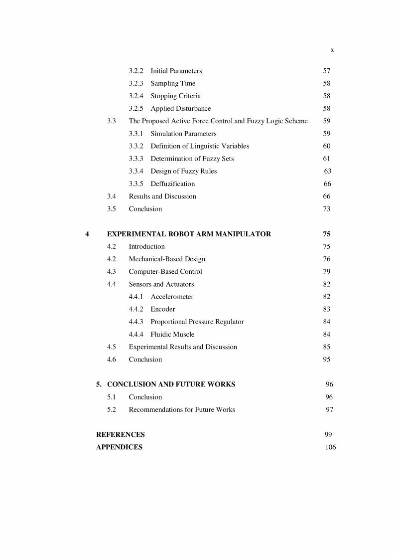
4 EXPERIMENTAL ROBOT ARM MANIPULATOR...........................75
4.2 Introduction ...................................................................................75
4.2 Mechanical-Based Design..............................................................76
4.3 Computer-Based Control ...............................................................79
4.4 Sensors and Actuators....................................................................82
4.4.1 Accelerometer ....................................................................82
4.4.2 Encoder..............................................................................83
4.4.3 Proportional Pressure Regulator .........................................84
4.4.4 Fluidic Muscle ...................................................................84
4.5 Experimental Results and Discussion.............................................85
4.6 Conclusion.....................................................................................95
5. CONCLUSION AND FUTURE WORKS ……………………………….96
5.1 Conclusion…………………………………………………………..96
5.2 Recommendations for Future Works………………………………..97
REFERENCES……………………………………………………………… 99
APPENDICES 106

xi
LIST OF TABLES
TABLE NO. TITLE PAGE
2.1 A comparison between different types of actuators 21
3.1 Acceleration 60
3.2 Trackerror………………………………………………………………... 60
3.3 Estimated inertia element IN1……………………………………………… 61
3.4 Estimated inertia element IN2……………………………………………… 61
3.5 Fuzzy rules…………………………………………………………………..64
4.1 Specifications of the rig……………………………………………………..79
4.2 Specifications of PCI-1710HG…………………………………………. 81

xii
LIST OF FIGURES
FIGURE NO. TITLE PAGE
1.1 Implementation of the research project 10
2.1 Basic operation of a pneumatic artificial muscle 19
2.2 Geometry of Festo Actuator. The braided fiber turns n times 24
2.3 Application of the virtual works theorem to the PAM 25
2.4 A representation of a two link arm 27
2.5 Skeleto-Muscle system of human elbow joint 30
2.6 Working Principle of antagonistic fluidic muscle actuator 30
2.7 Working Principle of antagonistic fluidic muscle actuator for two link arm.32
2.8 A general form of AFC scheme 33
2.9 A schematic diagram of proposed PID-AFC 34
2.10 PD type scheme 38
2.11 The interlinking of the proposed control scheme 39
2.12 A proposed AFCAIL scheme using a PD type algorithm ......................... 40
2.13 A flowchart showing the PD type learning algorithm applied to robot arm 41
2.14 Interpreting if-then rules 46
2.15 Graphical representation of the introductory example 47
2.16 Fuzzifying inputs 48
2.17 Application of fuzzy operator 49
2.18 Implication (minimum) method 49
2.19 Aggregate of all the individual outputs 50
2.20 Defuzzificarion 50
2.21 The proposed AFCAFL scheme 51
3.1 The Simulink diagram of AFCAIL 54
3.2 The Simulink diagram of Robot’s Dynamic model 55
3.3 The Simulink diagram of AFC 55

xiii
3.4 A window showing the equation representing the fluidic muscle 55
3.5 The Simulink diagram of AFCAFL 59
3.6 Angular acceleration as the input function 62
3.7 Trackerror as the input function 62
3.8 Estimated inertia matrix (IN1) as the output function 63
3.9 Estimated inertia matrix (IN2) as the output function 63
3.10 Rule editor 65
3.11 Surface viewer 65
3.12 Applied disturbance on each joint 68
3.13 Pulse input of link1 68
3.14 Pulse input of link2 68
3.15 Sine input of link1 69
3.16 Sine input of link2 69
3.17 PID performance of link 1 with pulse input 69
3.18 PID performance of link 2 with pulse input 70
3.19 PID performance of link 1 with sine input 70
3.20 PID performance of link 2 with sine input 70
3.21 AFCAIL performance of link 1 with pulse input 71
3.22 AFCAIL performance of link 2 with pulse input 71
3.23 AFCAIL performance of link 1 with sine input 71
3.24 AFCAIL performance of link 2 with sine input 72
3.25 AFCAFL performance of link 1 with pulse input 72
3.26 AFCAFL performance of link 2 with pulse input 72
3.27 AFCAFL performance of link 1 with sine input 73
3.28 AFCAFL performance of link 2 with sine input 73
4.1 Experimental rig made to test the fluidic muscle behaviour 77
4.2 The isometric view of the experimental rig using fluidic muscle as actuator77
4.3 experimental rig of two link planar robot arm 78
4.4 close-up view of the joint 2 78
4.5 The PCI-1710HG advantech 80
4.6 The mounting of the PCI-1710HG card in the PC 80
4.7 Schematic diagram of the experimental set-up 81
4.8 The ADXL330 Accelerometer 83
4.9 The Omron E6B2-C rotary encoder 83

xiv
4.10 Schematic and photo of the proportional pressure regulator 84
4.11 The fluidic muscles (DMAS models) manufactured by FESTO 85
4.12 Performance of link 1 using PID controller, f=0.05 Hz 86
4.13 Performance of link 2 using PID controller, f=0.05 Hz 86
4.14 Performance of link 1 using AFCAIL controller, f=0.05 Hz 87
4.15 Performance of link 2 using AFCAIL controller, f=0.05 Hz 87
4.16 Performance of link 1 using AFCAFL controller, f=0.05 Hz 88
4.17 Performance of link 2 using AFCAFL controller, f=0.05 Hz 88
4.18 Performance of link 1 using PID controller, f=0.05 Hz 89
4.19 Performance of link 2 using PID controller, f=0.05 Hz 89
4.20 Performance of link 1 using AFCAIL controller, f=0.05 Hz 89
4.21 Performance of link 2 using AFCAIL controller, f=0.05 Hz 90
4.22 Performance of link 1 using AFCAFL controller, f = 0.05 Hz 90
4.23 Performance of link 2 using AFCAFL controller, f = 0.05 Hz 90
4.24 Performance of link 1 using PID controller, f = 0.1 Hz 91
4.25 Performance of link 2 using PID controller, f = 0.1 Hz 91
4.26 Performance of link 1 using AFCAIL controller, f = 0.1 Hz 92
4.27 Performance of link 2 using AFCAIL controller, f = 0.1 Hz 92
4.28 Performance of link 1 using AFCAFL controller, f=0.1 Hz 92
4.29 Performance of link 2 using AFCAFL controller, f = 0.1 Hz 93
4.30 Performance of link 1 using PID controller, f = 0.1 Hz 93
4.31 Performance of link 2 using PID controller, f = 0.1 Hz 93
4.32 Performance of link 1 using AFCAIL controller, f = 0.1 Hz 94
4.33 Performance of link 2 using AFCAIL controller, f = 0.1 Hz 94
4.34 Performance of link 1 using AFCAFL controller, f = 0.1 Hz 94
4.35 Performance of link 2 using AFCAFL controller, f=0.1 Hz 95

xv
LIST OF ABBREVIATIONS
AFC Active force control
AFCAFL Active force control and fuzzy logic
AFCAIL Active force control and iterative learning
DOF Degree of freedom
FL Fuzzy logic
HILS Hardware-in-the-loop simulation
IL Iterative learning
PAM Pneumatic artificial muscle
PID Proportional-Integral-Derivative
xvi
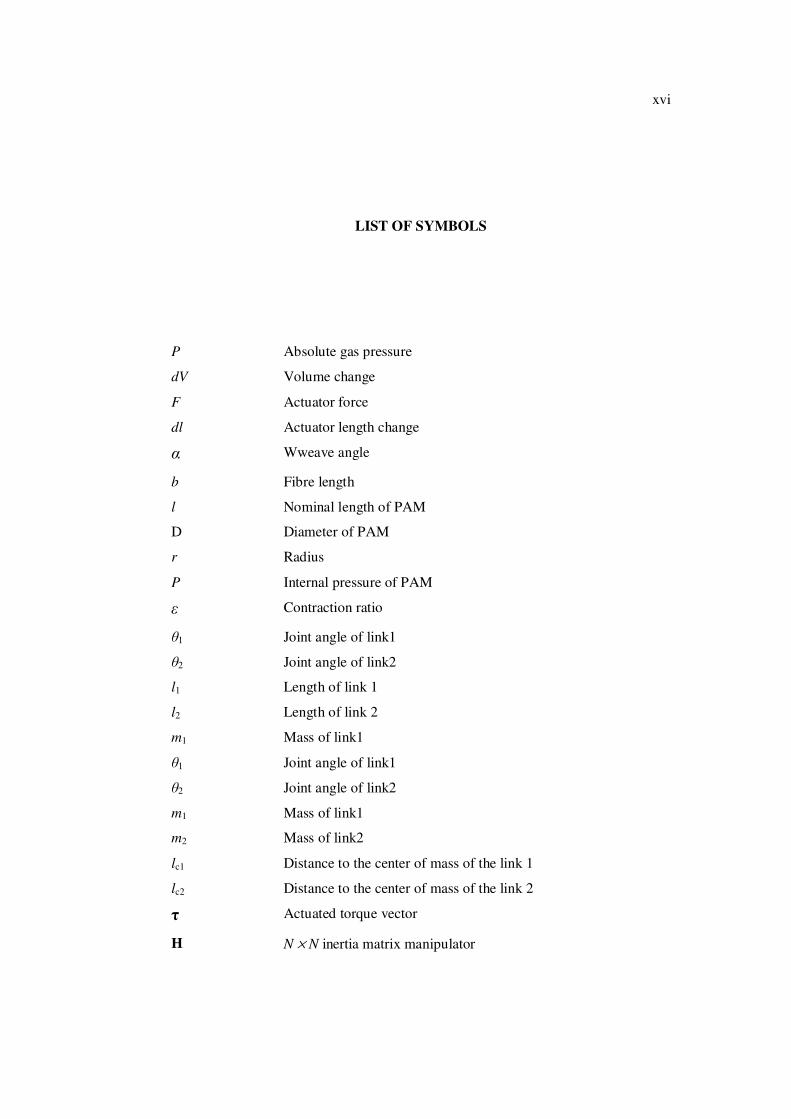
LIST OF SYMBOLS
P Absolute gas pressure
dV Volume change
F Actuator force
dl Actuator length change
� Wweave angle
b Fibre length
l Nominal length of PAM
D Diameter of PAM
r Radius
P Internal pressure of PAM
� Contraction ratio
�1 Joint angle of link1
�2 Joint angle of link2
l1 Length of link 1
l2 Length of link 2
m1 Mass of link1
�1 Joint angle of link1
�2 Joint angle of link2
m1 Mass of link1
m2 Mass of link2
lc1 Distance to the center of mass of the link 1
lc2 Distance to the center of mass of the link 2
� Actuated torque vector
H N × N inertia matrix manipulator
xvii
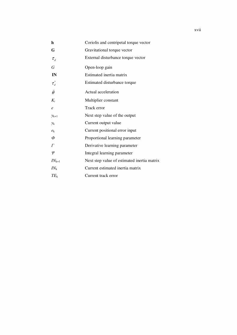
h Coriolis and centripetal torque vector
G Gravitational torque vector
dτ External disturbance torque vector
G Open-loop gain
IN Estimated inertia matrix
*dτ Estimated disturbance torque
� Actual acceleration
Ki Multiplier constant
e Track error
yk+1 Next step value of the output
yk Current output value
ek Current positional error input
� Proportional learning parameter
� Derivative learning parameter
� Integral learning parameter
INk+1 Next step value of estimated inertia matrix
INk Current estimated inertia matrix
TEk Current track error

xviii
LIST OF APPENDICES
APPENDIX TITLE PAGE A Mechanical Parts of the Experimental Rig 106
B Further Results: Performance of Various Control Schemes with f = 0.2 Hz 111
C Publications 115

CHAPTER 1
INTRODUCTION
1.1 General Introduction
Engineering principles are commonly applied to mechanical or
biomechanical systems to better understand the dynamics of the human arm. One
such system is the robotic arm or manipulator which is normally and geometrically
configured to resemble a human arm. A robust and stable performance of a robot arm
is essential as it handles the capability of the arm to compensate for the disturbance
effect, uncertainties, parametric and non parametric changes, which are prevalent in
the system particularly when the arm is executing tasks involving the interaction of
the robot’s end-effector with the environment and some kind of external
disturbances. The coordinated motion and force control of a robot arm is an
important subject area of research, which can directly contribute to the
accomplishment of such objective. A very desirable and effective robot control
system is one in which the issue of robustness is well accounted for. Many robots
control methods have been proposed such as proportional-integral-derivative (PID)
control [1], computed-torque control [2], intelligent control [3], and active force
control (AFC) [4]. It is a well-known fact that the conventional PID control is the
most widely and practically used scheme in the industrial robots due to its good
stability characteristic, simple controller structure, and reliability [1]. It provides a

2
medium to high performance when it comes to robot’s operation at relatively low
speed with little or no disturbance effects. On the contrary, the performance suffers
severe setbacks when adverse conditions prevail. A number of researches have been
conducted to seriously address the issue and determine ways to counter the weakness
[5, 6]. Thus, a feedback control system should be ideally chosen so that it is able to
overcome most if not all of the drawbacks and at the same time, it is practically
viable and can be implemented in real-world applications. Considering these factors,
the undertaken research project is an attempt to highlight the potentials of an AFC-
based method applied to a two-link planar robot arm actuated by pneumatic artificial
muscle (PAM) actuators.
1.2 Research Background and Contributions
Almost all the robot control methods contained the classical elements (of the
PID control), which contribute to the better overall performance of the system. One
such robot control method, which is of particular interest, is the active force control
strategy first proposed by Hewit in the late seventies [4]. The main feature of this
type of control method is the potential of the AFC concept to dynamical systems
including robot control. By implementing the AFC to the system, the effects due to
any known or unknown disturbances (internal or external), parametric changes and
varied operating conditions can be significantly compensated or eliminated. The
AFC method involves a direct measurement of the acceleration and force quantities
plus the appropriate estimation of the inertia matrix of effect in its control strategy.
Actuators are indispensable for all robots to provide forces, torques, and
mechanical motions to move the joint, limb or body. Actuators are generally electric,
pneumatic, or hydraulic. Today’s mechanical systems have such criteria for actuators
including high power density, high power to weight ratio, rapid response, accurate
and repeatable control, low cost, cleanliness and high efficiency. An important area
of robotics technology is concerned with the development of manipulators that can

3
replace human beings in the execution of specific tasks. This makes such qualities
such as lightweight, high power, and fast accurate response even more important for
actuators. The pneumatic artificial muscle (PAM) actuator possesses many of these
advantages, which therefore considered as an excellent candidate for robotic
applications. However, the inherent nonlinearities, time-varying parameters, and high
sensitivity to payload of the PAM make it a challenge for the accurate force and
position control of manipulators in employing these actuators.
It is the central theme of the undertaken research project to investigate the
implementation and the performance of a robot arm that is actuated and controlled by
PAM through the AFC-based scheme. In the proposed research, an intelligent
component is embedded into the AFC main loop to compute the appropriate inertia
matrix of the arm. Both the theoretical and experimental aspects were highlighted in
the study to validate and illustrate the practical viability of the proposed scheme.
The main research contributions can be summarised as follows:
1. The use of pneumatic artificial muscle (PAM) actuators to drive a two-
link robot manipulator that resembles a human arm.
2. Direct application of the AFC technique to the robot arm through both
simulation and experimental studies. The application of AFC to PAM
actuated system is indeed new area of research.
3. Incorporation of intelligent methods using fuzzy logic (FL) and iterative
learning (IL) algorithms to estimate the inertial parameters of the arms in
the AFC loop for the given system.
4. Development of an experimental rig with Hardware-in-the-Loop-
Simulation (HILS) to validate the proposed control scheme.

4
1.3 The Problem Statements
There are two main issues that need to be addressed and resolved in the
project. The first is related to the AFC scheme while the second is concerned with
the utilisation of the PAM actuator. Both are actually inter-related due to the fact that
the PAM actuator is designed as the main actuating element in the proposed control
schemes.
The AFC strategy is regarded very practical and effective if a number of
criteria can be fulfilled as follows:
1. Accurate measurements of the actuator torques and body angular
accelerations could be obtained.
2. A suitable inverse transfer function of the PAM actuator can be derived
and implemented.
3. A good estimated inertia matrix in the AFC loop can be computed.
The first criterion could be realized easily either through theoretical
investigation through simulation or experimental means using accurate sensors. The
second part is complex as it involves the application of the non-linear PAM and the
required function is derived based on the differential pressure of PAMs, �P. It is
typical that the third criterion is considered the most critical since it involves directly
the ever changing dynamics of a system and hence shall be described in greater detail
here. The estimated inertia matrix of the robotic arm can be derived from the
dynamic model as a function of joint angles which varies as the arm moves.
Mathematically, the computation of this matrix becomes increasingly difficult with
the corresponding increase in the number of degree-of-freedom (DOF) of the robot
arm. It is thus clear that the utilization of the inertia matrix based on the perfect
model of the robot arm with many DOF is quite impractical as far as the AFC
scheme is concerned. For a single DOF case, the solution to the above scheme is
rather straightforward and linear control theory is readily applicable. The proposed
research work assumes a two-link arm (and hence a two DOF system) which is
coupled and inherently non-linear - hence the computation of the estimated inertia
5
matrix is becoming increasingly difficult. It is evident that different system dynamics
produce correspondingly different operating environment related to the acquisition of
the estimated inertial parameters of the arm. Intelligent methods were proposed in the
study as the inertia matrix estimators of the arm driven by the highly non-linear PAM
actuators.
The other aspect is the use of the PAM actuator in the design and
development of the system. Research on the use of PAM actuator for controlling
purpose is relatively new and still in its infancy stage. The main characteristics of the
PAM actuator are the inherent non-linearities, time varying parameters and
sensitivity in the loading of the PAM system that posed great difficulty and challenge
in producing good coordinated motion control of a dynamic system including the
proposed robot arm. This is further exacerbated by the fact that there are not many
published works related to the area of study. On the whole, since the two-link planar
mechanical arm itself is a very nonlinear system plus the use of PAM actuators, the
proposed AFC–based scheme should be designed to be reliable, robust and effective
to tackle the aforementioned problems.
1.4 Research Objective
The main objective of the research is to investigate the performance of the
robotic arm actuated by fluidic muscle actuator through the application of AFC
strategy. To achieve this, the following sub-objectives are considered:
- To carry out theoretical study involving the modelling, simulation and
control of a two-link planar robot arm actuated by PAM.
- To validate the proposed AFC-based scheme through practical
experimentations on a developed rig.

6
1.5 Research Scope
The scope of the undertaken research is as follows:
• A two DOF planar robot arm is investigated considering motion in a horizontal
plane. Hence, gravitational effect can be totally ignored.
• Each joint of the arm is driven by a PAM actuator.
• The arm is assumed to operate at low speed and frequency due to the hysteresis
of the PAM. The only disturbances considered in the study are due to the
inherent non-linearity (including hysteresis) and other time varying parameters
(pressure and contraction ratio) of the PAM actuator.
• Theoretical design and simulation of a robust motion control of the arm is
based on AFC strategy. A class of PID control method is also employed for
benchmarking.
• Two intelligent methods using FL and IL algorithms are utilised to compute the
estimated inertial parameters of the system within the AFC loop.
• Design and development of an experimental PAM actuated two-link planar
system for validation and comparison.
1.6 Research Methodology
The project is divided into five main stages. The stages are modelling and
simulation, controller design, design and development of the rig, experimentation
and performance analysis. Mechatronic system design approach involving the
synergy of mechanical, electrical/electronics and computer (software) control would
be the main feature of the research methodology. The more detailed description of
the research methodology is described in the following sub sections.

7
1.6.1 Modelling and Simulation
As part of the mechatronic design process and prior to simulation, the system
has to be sufficiently modelled to include rigorous manipulation of the governing
mathematical equations representing the system dynamics and kinematics. The
modelling will take into account realistic and valid assumptions related to the main
dynamics of two-DOF robot arm, PAM actuator and disturbances based on the
classic Newtonian mechanics. Other components such as the controllers (PID and
AFC), reference inputs and the intelligent algorithms were mostly modelled based on
typical procedures described in the literature. Simulation study shall include the
evaluation of the system’s performance and robustness against the highly nonlinear
behaviour, hysteresis, and time-varying parameter of the actuators. Comparative
study between the control strategies shall also be done to provide a useful platform in
determining the best control method. The simulation works shall provide a good
basis for designing and developing the experimental rig in later stages. MATLAB
and Simulink software shall be the main design tool used for the simulation study.
Later, the same simulation can be used through a HILS technique that integrates the
hardware (sensors and actuators) and the software via MATLAB, Simulink and Real
Time Windows (RTW) Target facility.
1.6.2 Controller Design
Two main control methods were employed in the study using PID and AFC
methods. Both involve the use of simple control algorithms. In the former, the
controller parameters were obtained using the heuristic method through One-Value-

8
at-A-Time (OVAT) technique which is deemed sufficient. The robot PID control
(with all the relevant models considered, i.e. the dynamics of the robot arm, PAM
actuator, sensor, etc.) can be executed to observe the system performance.
Next the AFC technique is coupled directly to the PID controller. The AFC
parameters were acquired through perfect modelling of the sensors (for the torque
and acceleration measurements) and intelligent inertia matrix estimators via the FL
and IL algorithms. The intelligent algorithms were deliberately selected so that their
practical implementation in real-time is feasibly and readily applied to compute the
required parameters continuously and on-line as the system actually operates. Their
role in the proposed AFC-based scheme is indirect and supplementary in the sense
that they do not directly interfere with the controller main algorithm but rather
provide a method to complete the compensation strategy.
1.6.3 Design and Development of the Experimental Rig
The design and development of the proposed system is in-line with the
Mechatronics approach. In this approach, all the main aspects or disciplines of the
system are simultaneously or concurrently designed and integrated unlike the
traditional approach which is typically more sequential and segregated in nature.
This involves the integration of a number of classical engineering disciplines namely,
the mechanical, electrical/electronics and computer-based control. A complete
integration of the mentioned disciplines is thus very essential to realise a mechatronic
product.
• Mechanical: Mechanical design initially involves the conceptual design of
the physical two-link planar arm. A number of factors and suitable design criteria
should be carefully considered in the design process. The design process will include
conceptual and final design of the robot involving the development of suitable
mechanisms, static and dynamic analysis of the structure of the system, selection of

9
materials and others which are all referred to and should comply with the pre-
determined design criterion. A finalized design will be subsequently chosen with the
detailed production drawings ensued for fabrication purposes. Some of the
mechanical aspects of the system such as the computation of the parameters for the
length of pneumatic artificial muscle, dimensions of the system structure or parts can
be obtained and/or manipulated from the simulation study. The design should also
take into account the ease of the fabrication of the parts to be processed.
• Electrical/Electronics: The selection of the actuator system should be based
on the force analysis of the system to ensure proper actuation of the system is
achieved. Pneumatic artificial muscle-with high power-weight ratio, compliant
nature and whereas their behavior is like muscle can be a suitable actuator to derive a
robotic arm. A good knowledge and skill in electronics assembly is highly desirable
at this stage. Again, the outcome from the simulation works help in determining for
example the size (power, force, torque etc.) of the actuators to be used.
• Computer-based Control: The next stage will involve rigorous computer
interfacing and control involving data acquisition process through the DAQ card and
a PC for software control. Matlab and Simulink serve as the link between the
mechanical and electrical/electronics components.
1.6.4 Experimentation
When the mechatronic system prototype is ready, experimental procedures
will be drafted and testing will be done to validate the effectiveness and the
robustness of the control strategy. Possible modification of the system can be carried
out at this stage to enhance the system’s performance. Experimentation will be
rigorously carried out to test the effectiveness of the proposed system. The tests will
take into account various operating and loading conditions.

10
1.6.5 Performance Evaluation and Analysis
The systems performance will be critically evaluated and analyzed based on
the trajectory tracking capability (accurate position control) of the schemes
considering the effect of inherent non-linearities and disturbances in the system. The
trajectory tracking errors produced by the respective control schemes shall be the
basis for the study of the performance in executing the given tasks. This includes the
results obtained from both the simulated and experimental rig developmental
activities. The research outcomes should provide insights and information which
would be useful for future development, improvement and expansion of the system.
In addition to that, suggestion for further research works will also be outlined.
Figure 1.1 shows the flow chart of the proposed research methodology.
Start
Literature Review
Controller Design
Modelling the PAM and the two link robot arm
Simulation study on two link robot arm
Design and development of experimental rig
Experimental study
Report on the study
Performance evaluation and analysis
Figure 1.1: Implementation of the research project

11
1.7 Organization of Thesis
The thesis is organized into five chapters. In Chapter 2, the fundamental
concepts, underlying theories and reviews of the main topics of research pertaining to
modelling of the kinematics and dynamics of the robotic arm and its control,
pneumatic artificial muscle, PID control, AFC, FL and IL algorithms are described.
The modelling of the two link planar resembled as human-like arm and principles,
characteristics and modelling of pneumatic artificial muscle are described as this
provides the basis for the simulation of the control system. Next, the principles of the
PID and the pure AFC method are discussed with special attention focused on the
method to enhance the strategy using intelligent means, namely IL and FL methods.
An inertia matrix estimation method using fuzzy logic for an AFC scheme is
presented. The fuzzy logic mechanism computes the estimated inertia matrix (IN)
automatically and continuously, while the robot arm is tracking the reference input
that is followed by AFC incorporate with iterative learning (AFCIL). IL is embedded
in the AFC strategy to estimate the estimated inertia matrix (IN) to control the
performance of the robot arm.
Chapter 3 presents the simulation study of proposed controllers, AFCIL and
AFCAFL based on some of the theoretical concepts and principles derived from
previous chapter. Then, the comparative study of the proposed control schemes is
described with a particular emphasis laid on the technique used to compute the
estimated inertia matrix and the trajectory track performance of the proposed control
schemes.
The experimental study is done in Chapter 4 to compliment the theoretical
works. Mechatronics concept is applied here as it involves the rigorous integration of
the mechanical, electronics and computer control disciplines.

12
Finally, Chapter 5 concludes the research project and the directions for the
future works are outlined. Some of the additional materials pertaining to sketch of rig
parts, mechatronics parts catalogue, publications and achievements related to the
research are enclosed in the appendices.