intellibrite 5g color pool and spa lights · intellibrite® 5g white pool and spa led light...
TRANSCRIPT

INTELLIBRITE® 5G White Pool and Spa LED Light Installation and User’s Guide
IMPORTANT SAFETY INSTRUCTIONSREAD AND FOLLOW ALL INSTRUCTIONS
SAVE THESE INSTRUCTIONS
INSTALLATION ANDUSER’S GUIDE
INTELLIBRITE® 5G
COLOR POOL AND SPA LIGHTS

INTELLIBRITE® 5g Color Pool and Spa Lights Installation and User’s Guide
Technical Support Phone: (800) 831-7133 - Fax: (800) 284-4151
Web sites: www.pentairpool.com and www.staritepool.com:
ContentsIMPORTANT WARNING AND SAFETY INSTRUCTIONS...................................... iIntelliBrite 5g Color Pool and Spa Lights Overview ............................................... 1
Operating IntelliBrite lights using a wall switch (12 VAC)....................................... 1
Using an External Safety Isolation Transformer for Multiple IntelliBrite 12 VACLights ............................................................................................................................ 1
IntelliBrite 5G Color Pool and Spa Light Models..................................................... 2
Troubleshooting ......................................................................................................... 2
Operating IntelliBrite Color Pool and Spa Lights Using a Wall Switch................ 2
Selecting a light show mode of fixed color ......................................................... 3
Replacing the IntelliBrite Color Pool and Spa Light Assembly(in an existing pool) .................................................................................................... 5
Replacing the IntelliBrite Color Pool and Spa Light Assembly(after electrical Requirements are met) ................................................................... 6
Installing the IntelliBrite Color Pool and Spa Light Fixture(new pool construction) .............................................................................................. 8
Installing the IntelliBrite Color Pool and Spa Light Fixture(after electrical requirements are met)...................................................................... 9
Replacing the IntelliBrite Color Pool Light Circuit Board Assembly
(in an existing pool)..................................................................................................... 11
Replacing the IntelliBrite Color Pool Light Circuit Board Assembly
With New Gasket ........................................................................................................ 13
Wide and Narrow Angle Lens Adjustment........................... ................................ ...16
IntelliBrite 5g Color Pool Light Replacement Kit Part Numbers ...........................17
Replacing the IntelliBrite Color Spa Light Face ring and Gasket(P/N 640045) or Gasket and Lens (640046) ......................................................... .17
Replacing the IntelliBrite Color Spa Light Face Ring and Gasketor Gasket and Lens ................................................................................................... 19
IntelliBrite 5g Color Spa Light Replacement Kit Part Numbers .......................... 23
READ AND FOLLOW ALL INSTRUCTIONSSAVE THESE INSTRUCTIONS

INTELLIBRITE® 5g Color Pool and Spa Lights Installation and User’s Guide
i
Most states and local codes regulate the construction, installation, andoperation of public pools and spas, and the construction of residential
pools and spas. It is important to comply with these codes, many of which directlyregulate the installation and use of this product. Consult your local building and healthcodes for more information.
SERIOUS BODILY INJURY OR DEATH CAN RESULT IF THIS LIGHTIS NOT INSTALLED AND USED CORRECTLY.
INSTALLERS, POOL OPERATORS AND POOL OWNERS MUSTREAD THESE WARNINGS AND ALL INSTRUCTIONS BEFOREUSING THE POOL AND/OR SPA LIGHT.
Before installing this product, read and follow all warning noticesand instructions in this Guide. Failure to follow warnings and
instructions can result in severe injury, death, or property damage.Call (800) 831-7133 for additional free copies of these instructions. Please refer towww.pentairpool.com for more information related to this products.
IMPORTANT NOTICE - Attention Installer: This Installation and User’sGuide (“Guide”) contains important information about the installation,operation and safe use of this underwater pool and spa light. This Guideshould be given to the owner and/or operator of this equipment.
IMPORTANT WARNING AND SAFETY INSTRUCTIONS
BEFORE WORKING ON INTELLIBRITE LIGHTS! Always disconnectpower to the pool and/or spa lights at the circuit breaker from thelight before servicing the light. Failure to do so could result indeath or serious injury to service person, pool users or othersdue to electric shock.
RISK OF ELECTRICAL SHOCK OR ELECTROCUTION:
This underwater light must be installed by a licensed or certified electrician or aqualified pool professional in accordance with the current National Electrical Code(NEC), NFPA 70 or the Canadian Electrical Code (CEC), CSA C22.1. All applicablelocal installation codes and ordinances must also be adhered to. Improper installationwill create an electrical hazard which could result in death or serious injury to poolusers, installers or others due to electrical shock, and may also cause damage toproperty. Always disconnect the power to the pool light at the circuit breaker beforeservicing the light. Failure to do so could result in death or serious injury toserviceman, pool users or others due to electrical shock. READ AND FOLLOW ALL INSTRUCTIONS IN THIS MANUAL.
Important Safety Information for Pentair Aquatic Systems(“Pentair”) Niche and Light Installation
• All Niche and Light installations must conform with all codes. If local codesmandate a cord seal, use Pentair plastic niches(P/N 79206600 and P/N 79206700) and Cord Seal Kit (P/N 670044).
• Under no circumstances replace lights by splicing wire under water orbehind niche.
IntelliBrite® 5g Color Pool and Spa lights REQUIRE HIGH VOLTAGEWHICH CAN SHOCK, BURN, OR CAUSE DEATH.

INTELLIBRITE® 5g Color Pool and Spa Lights Installation and User’s Guide
For countries in compliance with International ElectromechnicalCommission (IEC) regulatory standards: The light fixture must be
installed by a licensed or certified electrician or a qualified pool service person, inaccordance with IEC 364-7-702 and all applicable current local codes and ordinance.Improper installation will create an electrical hazard, which could result in death orserious injury to pool user, installer or other due to electrical shock and may also causedamage to the property.
ii
IMPORTANT WARNING AND SAFETY INSTRUCTIONS
RISK OF ELECTRIC SHOCK AND INJURY. USE ONLY THE
fonoitacoLesUerianimuL
*erutxiFniatnuoFapSdnalooPretaWriatneP)000065N/Pdna100065N/P(
dohteMnoitallatsnIderiuqeR
looPgnimmiwSapSdna
looPgnimmiwSehciN-teW)thgiL(erianimuL)apSro(
.YLNO)llehSgnimroF(gnisuoHerutxiFESUTONOD .dnatSerutxiFniatnuoF
niatnuoF )thgiL(erianimuLelbisrembuSehciN-teW)thgiL(rianimuL)apSro(looPgnimmiws
ro)llehSgnimroF(gnisuoHerutxiF.dnatSerutxiFniatnuoF
(*) Note: Wet-niche luminaires complying with requirements for both uses may bareboth the Listed Wet-Niche Submersible Luminaires UL Mark. A luminaire not bearingthe corresponding UL Listing Mark is not considered by UL to have been producedunder UL’s Listing and Follow-Up Service for the associated usage location.
CAUTION - The Pentair IntelliBrite® Light fixture must only be used with Pentair fixturehousings (niches). If the IntelliBrite light fixture is installed into other niches, theinstallation will not carry U.L. approval and will void all warranties.
Salt is an inherently corrosive material. While the levels of salt requiredfor proper operation of an electronic chlorine generator are relatively
low when compared to sea water and other salt solutions, placing any amount of salt inyour pool increases the likelihood of corrosion or other deterioration of pool equipmentand any surfaces used in and around your pool. Metal parts and certain natural andman-made surfaces are particularly susceptible to corrosion and deterioration whenused in and around salt water pools. Pentair does not represent or otherwise guaranteethat the proper use of an electronic chlorine generator will prevent corrosion or otherdeterioration of pool equipment and any surfaces used in and around your pool. Consultyour experienced pool professional, who should be able to advise you on the propermaterial selection, installation techniques for those materials, and the proper use, careand maintenance of those materials for your specific pool type and location in order tominimize the corrosion and deterioration that is inherent in and around salt water pools.
INSTALLATION METHOD SPECIFIED BELOW.
NOTICE: The external flexible cable or cord of this luminaire cannot be replaced; ifthe cord is damaged, the luminaire shall be destroyed.
- REPLACE ANY CRACKED PROTECTIVE SHIELD (CRACKED LENS) WITH NEW LENS AND GASKET. FOR MORE INFORMATION SEE PAGE 11.- FOR LIGHT OPERATION, ONLY USE A SAFETY ISOLATION TRANSFORMER. FOR MORE INFORMATION SEE PAGE 9.
POOL AND SPA FIXED LUMINARIES: Follow these guidelines when installing,replacing or reparing Pentair Aquatic Systems Pool and Spa fixed luminaries:
Pentair Aquatic Systems Fountain Fixture*

INTELLIBRITE® 5g Color Pool and Spa Lights Installation and User’s Guide
1
IntelliBrite® 5g Color Pool and Spa Lights Overview
The IntelliBrite® 5g Color Pool and Spa lights system gives you brilliant vivid multi-colorswith spectacular effects for your pool. The energy efficient colored LED array utilizesIntelliBrite® color light technology and can cycle through colors at varying speeds and indifferent sequences of color. Choose one of the seven pre-programmed color light showsor select one of the five fixed colors to create virtually endless range of dramaticunderwater lighting effects for a spectacular effect in your pool and spa. The IntelliBritelens geometry (pool light only) provides a choice between two light beam shapes; widercoverage with less intensity, or narrower coverage with more intensity. For moreinformation, see page 16.
Operating Pool and Spa Lights Using a Wall Switch (12 VAC)The color pool and spa lights can be manually controlled using a standard wall-mountlight switch. Multiple IntelliBrite lights can be connected via a junction box and a 12 VACtransformer to a single switch so that all lights can be switched on and off together.IntelliBrite lights can also be automatically controlled via Pentair IntelliTouch®,EasyTouch® and SunTouch® Control Systems. For more information refer to theIntelliTouch User’s Guide (P/N 521075), EasyTouch User’s Guide (P/N 521044), andSunTouch User’s Guide (P/N 520785).
Using an External Safety Isolation Transformer for MultipleIntelliBrite 12 VAC LightsWhen using multiple IntelliBrite 12 VAC lights on a 300 Watt safety isolation transformer,it is recommended that no more than three IntelliBrite pool lights and one (1) IntelliBriteSpa light be used. It is also recommended not to exceed 100 feet of total cable runbetween the transformer and light (see diagram on page 2).
OVERVIEW
300 WattTransformer J Box12 Gauge
(minimum)
150 ft. max. for spa light
200 ft. max. for pool light
300 WattTransformer J Box12 Gauge
(minimum)
100 ft.

INTELLIBRITE® 5g Color Pool and Spa Lights Installation and User’s Guide
melborP noitcA/esuaC
.etanimullitonlliwthgilehT
.ylreporpnoitcnuftonseodthgiL
.yrassecenfiteserdnagniriwtluafdnuorgICFGehtkcehC
edisloopehttaxobnoitcnujehtotnoitcennocgniriwthgilehtkcehC.hctiwsrewopCAehtotdna
.thgilehtotdeilpparewopCAreporpsierehttahteruseB
Troubleshooting
2
Operating IntelliBrite Color Pool and Spa LightsUsing a Wall Switch
IntelliBrite 5g Color Pool and Spa lights can be controlled using a standard wall-mount light switch. Multiple IntelliBrite lights can be connected via a junction boxto a single switch so that all lights can be switched on and off together. IntelliBritelights are controlled by cycling AC power from a standard wall switch. By turningthe switch on and off a specific number of times, the light activates one of theseven light show modes, fixed colors, and enables the “Hold” and “Recall” feature.
Powering on the light
When the IntelliBrite light is powered on, a momentarily white light will illuminate,followed by the previously selected color.Note: If power to the light is off for more than five (5) seconds, the last color showmode or fixed color that was saved will be displayed.
IntelliBrite® 5g Color Pool Light models:There are two IntelliBrite 5g Color Pool light models:
• IntelliBrite 5g Color Pool Light; 120 VAC, with integrated 12 VACtransformer. P/N 60100x (UL certified), P/N 60200x (CSA certified), 50 ft.cord length - Other cord lengths are available from 30 ft. (9.14 m) to 250ft. (76.2 m).
• IntelliBrite 5g Pool Light; 12 VAC, (requires 120 VAC to 12 VACtransformer). P/N 60101x (UL certified), P/N 60201x (CSA certified), 50 ft.cord length - Other cord lengths are available from 30 ft. (9.14 m) to 150 ft.(45.72 m).
Note: For IntelliBrite 5g Color Pool Light replacement parts list, see page 17-18.
IntelliBrite 5g Color Spa Light models
There are two IntelliBrite Color Spa light models:• IntelliBrite 5g Color Spa Light, 120 VAC, with integrated 12 VAC
transformer, 50 ft. cord length (P/N 640121) - Other cord lengths areavailable from 30 ft. (9.14 m) to 250 ft. (76.2 m).
• IntelliBrite 5g Color Spa Light, 12 VAC, (requires 120 VAC to 12 VACtransformer), 50 ft. cord length (P/N 640131) - Other cord lengths areavailable from 30 ft. (9.14 m) to 150 ft. (45.72 m).
Note: For IntelliBrite 5g Color Spa Light replacement parts list, see page 23.
INTELLIBRITE® 5g Color Pool and Spa Lights Installation and User’s Guide
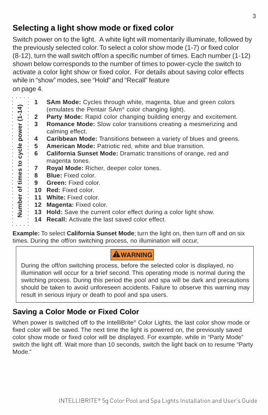
Selecting a light show mode or fixed colorSwitch power on to the light. A white light will momentarily illuminate, followed bythe previously selected color. To select a color show mode (1-7) or fixed color(8-12), turn the wall switch off/on a specific number of times. Each number (1-12)shown below corresponds to the number of times to power-cycle the switch toactivate a color light show or fixed color. For details about saving color effectswhile in “show” modes, see “Hold” and “Recall” featureon page 4.
3
1 SAm Mode: Cycles through white, magenta, blue and green colors(emulates the Pentair SAm® color changing light).
2 Party Mode: Rapid color changing building energy and excitement.3 Romance Mode: Slow color transitions creating a mesmerizing and
calming effect.4 Caribbean Mode: Transitions between a variety of blues and greens.5 American Mode: Patriotic red, white and blue transition.6 California Sunset Mode: Dramatic transitions of orange, red and
magenta tones.7 Royal Mode: Richer, deeper color tones.8 Blue: Fixed color.9 Green: Fixed color.10 Red: Fixed color.11 White: Fixed color.12 Magenta: Fixed color.13 Hold: Save the current color effect during a color light show.14 Recall: Activate the last saved color effect.
Nu
mb
er o
f ti
mes
to
cyc
le p
ow
er (
1-14
)
Example: To select California Sunset Mode; turn the light on, then turn off and on sixtimes. During the off/on switching process, no illumination will occur,
During the off/on switching process, before the selected color is displayed, noillumination will occur for a brief second. This operating mode is normal during theswitching process. During this period the pool and spa will be dark and precautionsshould be taken to avoid unforeseen accidents. Failure to observe this warning mayresult in serious injury or death to pool and spa users.
Saving a Color Mode or Fixed ColorWhen power is switched off to the IntelliBrite® Color Lights, the last color show mode orfixed color will be saved. The next time the light is powered on, the previously savedcolor show mode or fixed color will be displayed. For example, while in “Party Mode”switch the light off. Wait more than 10 seconds, switch the light back on to resume “PartyMode.”
INTELLIBRITE® 5g Color Pool and Spa Lights Installation and User’s Guide
4
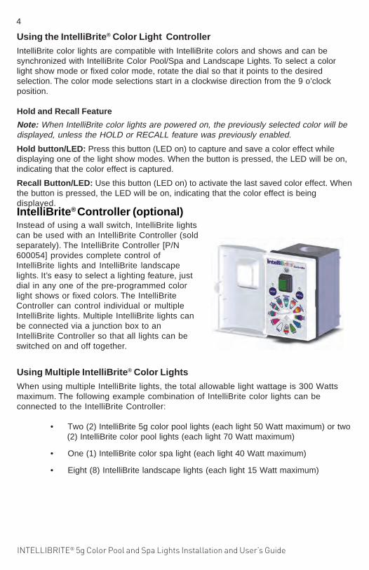
Instead of using a wall switch, IntelliBrite lightscan be used with an IntelliBrite Controller (soldseparately). The IntelliBrite Controller [P/N600054] provides complete control ofIntelliBrite lights and IntelliBrite landscapelights. It’s easy to select a lighting feature, justdial in any one of the pre-programmed colorlight shows or fixed colors. The IntelliBriteController can control individual or multipleIntelliBrite lights. Multiple IntelliBrite lights canbe connected via a junction box to anIntelliBrite Controller so that all lights can beswitched on and off together.
IntelliBrite® Controller (optional)
Using the IntelliBrite® Color Light ControllerIntelliBrite color lights are compatible with IntelliBrite colors and shows and can besynchronized with IntelliBrite Color Pool/Spa and Landscape Lights. To select a colorlight show mode or fixed color mode, rotate the dial so that it points to the desiredselection. The color mode selections start in a clockwise direction from the 9 o’clockposition.
Hold and Recall Feature
Note: When IntelliBrite color lights are powered on, the previously selected color will bedisplayed, unless the HOLD or RECALL feature was previously enabled.
Hold button/LED: Press this button (LED on) to capture and save a color effect whiledisplaying one of the light show modes. When the button is pressed, the LED will be on,indicating that the color effect is captured.
Recall Button/LED: Use this button (LED on) to activate the last saved color effect. Whenthe button is pressed, the LED will be on, indicating that the color effect is beingdisplayed.
Using Multiple IntelliBrite® Color LightsWhen using multiple IntelliBrite lights, the total allowable light wattage is 300 Wattsmaximum. The following example combination of IntelliBrite color lights can beconnected to the IntelliBrite Controller:
• Two (2) IntelliBrite 5g color pool lights (each light 50 Watt maximum) or two(2) IntelliBrite color pool lights (each light 70 Watt maximum)
• One (1) IntelliBrite color spa light (each light 40 Watt maximum)
• Eight (8) IntelliBrite landscape lights (each light 15 Watt maximum)

INTELLIBRITE® 5g Color Pool and Spa Lights Installation and User’s Guide
Risk of Electrical Shock or Electrocution!This underwater light must be installed by a licensed or certifiedelectrician or a qualified pool professional in accordance withthe current National Electrical Code and all applicable localcodes and ordinances. Improper installation will create anelectrical hazard which could result in death or serious injury topool users, installers or others due to electrical shock, and mayalso cause damage to property.
Always disconnect the power to the pool light at the circuitbreaker before servicing the light. Failure to do so could result indeath or serious injury to serviceman, pool users or others dueto electrical shock.
Note: The pool and spa electrical system can be verified with a Pooland Spa Electrical Qualification Test Kit. The electrical systeminspection using this kit must be performed by trained and certifiedpersonnel.•. To be certain that the pool’s electrical system meets all applicable
requirements, the electrician should also consult the localbuilding department.
• Use only Pentair wet niches to insure proper bonding and
grounding connections.
Replacing the IntelliBrite® Color Pool and SpaLight Assembly
(in an existing pool or spa)
Verify that the pool and spa meets the requirements of the current NationalElectrical Code and all local codes and ordinances. A licensed or certifiedelectrician must install the electrical system to meet or exceed thoserequirements before the underwater light is installed. Some of the requirementsof the current National Electrical Code which the pool’s electrical system mustmeet are as follows:• The lighting circuit has a Ground Fault Circuit Interrupter (GFCI) for line
voltage models, and has an appropriately rated circuit breaker.• The Junction Box (or, for 12 volt models, the low voltage transformer) is
located at least eight (8) inches (20.3 cm) above ground level and at least48 inches (1.219 m) from the edge of the pool; see Figure 1 on page 9.
• The light fixture and all metal items within five (5) feet (1.524 m) of the poolare properly electrically bonded.
• The wet niche is properly installed so that the top edge of the underwaterlight’s lens is at least 18 inches below the surface of the water in the pool;see Figure 1 on page 9.
• The wet niche is properly electrically bonded and grounded via the No.8 AWG ground connector located at the rear of the niche; see Figure 1on page 9.
5

INTELLIBRITE® 5g Color Pool and Spa Lights Installation and User’s Guide
The following removal and installation instructions describe how to remove andinstall the IntelliBrite color pool and color spa light assembly. Also use theseinstructions after completing the following light replacement procedure:
• IntelliBrite Color Spa Light and Face Ring Gasketand Lens Removal and Installation instructions, onpage 19. Always install a new lens gasket (partnumber 79101601).
1. WARNING! Switch off main electrical switch or circuit breaker, and theswitch which operates the IntelliBrite underwater light.
2. To remove light fixture assembly from the pool. Remove the specialbronze pilot screw at top of face ring. Remove the IntelliBrite light assemblyfrom the niche and place it on the deck.
3. Cut the cord about 12 inches (30.5 cm) from the back of the lightassembly.
4. Remove Junction Box cover, disconnect the light fixture wires, andpull the cord through the conduit. Tip: Before pulling the cord, tapethe new cord to the existing cord, This might make it easier tofeed the new cord through the conduit (see following step).
5. Feed the new light fixture cord through the conduit from the niche tothe Junction Box. Note: Depending on the length of the conduit,special tools may be required to pull the cord through the conduit.
6. Leave at least four (4) feet of cord to coil around the light fixture; seeFigure 1 on page 9. This four (4) feet (1.2192 m) of cord coiled aroundthe light allows the light to be serviced after the pool is filled withwater.
7. Cut the cord at the Junction Box, leaving at least size (6) inches ofcord to make connections.
8. Strip six (6) inches (15.2 cm) of the outer cord jacket from the cord toexpose the three insulated conductors. Be careful not to damage theinsulation on the three (3) inner conductors). Strip a 1/2” of insulation offthe three conductors. Be careful not to damage the copper conductor.
Failure to bring the pool or spa’s electrical system up to code requirementsbefore installing the underwater light will create an electrical hazard whichcould result in death or serious injury to pool users, installers, or others due toelectrical shock, and may also cause damage to property.
Replacing the IntelliBrite® Color Pool and SpaLight Assembly
(After Electrical Requirements Are Met)
6

INTELLIBRITE® 5g Color Pool and Spa Lights Installation and User’s Guide
10. Install the IntelliBrite light assembly into the niche and tighten the specialbronze pilot screw.
Use only the special pilot screw provided with thisunderwater light. This screw mounts and electrically grounds the housingsecurely to the mounting ring and wet niche. Failure to use the screwprovided could create an electrical hazard which could result in death orserious injury to pool users, installers or others due to electrical shock.
11. Final check for proper IntelliBrite light operation: Switch on themain switch or circuit breaker to the system, and the switch thatoperates the IntelliBrite underwater light itself. The light shouldilluminate when power is applied. If not recheck the installation stepsstarting with Step 1 (page 6).
9. Connect all three conductors to the corresponding circuit wires in theJunction Box (black wire to power, color wire to common, and greenwire to ground) and secure the Junction Box cover in place.
7
IntelliBrite 5G Pool Light
Pilot screw (bronze)
IntelliBrite 5G Spa Light
Pilot screw (bronze)

INTELLIBRITE® 5g Color Pool and Spa Lights Installation and User’s Guide
8
The following describes how to install the IntelliBrite Color Pool and Spa ColorLight fixture. Read page 3 before starting the installation procedure.
Be sure that the pool or spa meets the requirements of the current National ElectricalCode (N.E.C.) Article 680-22 and all local codes and ordinances. A licensed orcertified electrician must install the electrical system to meet or exceed thoserequirements before the underwater light is installed. Some of the requirements ofthe National Electrical Code which the pool’s electrical system must meet are asfollows:
BEFORE STARTING: The following steps 1-7 (page 6-7) describe the tasks thatmust be completed by the electrician before the IntelliBrite light fixture isinstalled. See Figure 1 diagram on page 9.
Note: The pool or spa electrical system can be verified with a Pool and Spa Electrical
Qualification Test Kit. The electrical system inspection using this kit must be performedby trained and certified personnel. Note: To be certain that the pool or spa electricalsystem meets all applicable requirements, the electrician should also consult thelocal building department. Use only Pentair spa wet niches to insure proper bondingand grounding connections.
INTELLIBRITE® COLOR POOL AND SPA LIGHT FIXTUREINSTALLATION (NEW POOL CONSTRUCTION)
• The lighting circuit has a Ground Fault Circuit Interrupter (GFCI) for 120VAC line voltage models, and has an appropriately rated circuit breaker.The conductors on the load side of the GFCI circuit shall not occupyconduit, boxes, or enclosures containing other conductors unless theadditional conductors are also protected by a GFCI. Refer to local codes forcomplete details.
• The Junction Box (or, for 12 volt models, the low voltage transformer) islocated at least eight (8) inches (20.3 cm) above water level and at least 48inches (1.22 m) from the edge of the pool. See Figure 1 on page 6.
• The light fixture and all metal items within five (5) feet (1.524 m) of the poolare properly electrically bonded.
• The wet niche is properly electrically bonded and grounded via the No. 8AWG ground connector located at the rear of the niche; see Figure 1.
• The wet niche is properly installed so that the top edge of the underwaterlight’s lens is at least 18 inches below the surface of the water in the pool;see Figure 1 on page 9.
• The light niche must be properly installed so that the top edge of theAmerBrite light’s lens is at least 18” minimum below (not more than 48inches below in Canada) the surface of the water in the pool or spa.
• Be certain that the pool or spa electrical system meets all applicablerequirements, the electrician should also consult the local buildingdepartment.

INTELLIBRITE® 5g Color Pool and Spa Lights Installation and User’s Guide
ite Color light (after electrical requirements are met)
1. Route light cable through conduit to Junction Box, leaving at least four (4)feet of cable at the light fixture to coil around the light (this allows the light tobe serviced after the pool is filled with water). See Figure 1 below.
9
Figure 1.
To install the IntelliBrite Color Light fixture:
INSTALLING THE INTELLIBRITE® COLOR POOL AND SPA LIGHTFIXTURE (AFTER ELECTRICAL REQUIREMENTS ARE MET)
2. Cut the cable at the Junction Box, leaving at least six (6) inches (2.4 cm) ofcord to make connections.
3. Strip back six (6) inches (2.4 cm) of the outer cord jacket to expose thethree insulated conductors (be careful not to damage the insulation on thethree (3) inner conductors). Strip a 1/2” of insulation off the threeconductors. Be careful not to damage the copper conductor.
4. Connect all three (3) conductors to the corresponding circuit wires in theJunction Box and secure the Junction Box cover in place.
FOR LIGHT OPERATION, ONLY USE A SAFETY ISOLATION TRANSFORMER.Note: Connect all three wires to the corresponding circuit wires in the Junction Box(black wire to power, white wire to common, and green wire to ground). FIXED POOLAND SPA LUMINARIES SPECIFICATION: 12 VAC 50/60 Hz - 120VAC 50/60 Hz

INTELLIBRITE® 5g Color Pool and Spa Lights Installation and User’s Guide
10
5. Install the IntelliBrite® Color Light assembly into the niche and tighten thespecial bronze pilot screw.
Use only the special pilot screw provided with thisunderwater light. This screw mounts and electrically grounds the housingsecurely to the mounting ring and wet niche. Failure to use the screwprovided could create an electrical hazard which could result in death orserious injury to pool users, installers or others due to electrical shock.
6. Fill the pool until the underwater light is completely submerged in waterbefore operating the light.
7. Final check for proper light operation: To check for proper operation,switch on the main switch or circuit breaker, and the switch that operatesthe IntelliBrite underwater light itself. The light should illuminate whenpower is applied. If not recheck the installation steps starting with Step 1(page 6)
FOR INTELLIBRITE COLOR POOL AND SPA LIGHT REMOVAL ANDINSTALLATION INSTRUCTIONS SEE:
• IntelliBrite Color Pool Light Removal and Installation instructions, on page 5.• IntelliBrite Color Spa Light Removal and Installation instructions, on page 19.
IntelliBrite 5G Pool Light
Pilot screw (bronze)
IntelliBrite 5G Spa Light
Pilot screw (bronze)

INTELLIBRITE® 5g Color Pool and Spa Lights Installation and User’s Guide
11
1. Turn off main electrical switch or circuit breaker, as well as the switchwhich operates the IntelliBrite pool light. Note: It is not necessary to draindown the pool to replace the light.
2. Before starting make sure that you have a new lens gasket (P/N 79101601)and a IntelliBrite 5g color pool light assembly (P/N 619818Z) ready toinstall.
3. REMOVE THE INTELLIBRITE COLOR POOLLIGHT ASSEMBLY: Remove the PILOT screw attop of face ring, then remove the light assemblyfrom the niche by tilting the top away from the nicheand then lifting the light assembly from the lockingtab at the bottom of the niche.
4. Unwind the cord from the base of the light housing.
Be sure to keep the pilot screw from the IntelliBriteunderwater light. This screw mounts and electrically grounds the
housing securely to the mounting ring and wet niche. Failure to use the screwprovided could create an electrical hazard which could result in death or seriousinjury to pool users, installers or others due to electrical shock.
REPLACING THE INTELLIBRITE® COLOR POOL LIGHT CIRCUITBOARD ASSEMBLY (IN AN EXISTING POOL)
Replace the light assembly with the same type and wattage.Failure to replace the light assembly with the same type will
damage the light assembly and may cause an electrical hazard resulting in deathor serious injury to pool users, installers, or others due to electrical shock, and mayalso cause damage to property.
Removal and Installation of IntelliBrite 5g Color Light Circuit Board
D A N G E R !
RISK OF ELECTRICAL SHOCK OR ELECTROCUTIONAlways disconnect power to the pool light at the circuitbreaker before servicing the light. Failure to do so couldresult in death or serious injury to installer, service person,pool users, or others due to electrical shock.
When replacing or reassembling the IntelliBrite® Color Pool Light, theGasket (P/N 79101601) or Gasket and Lens (619864Z) MUST ALSO BEREPLACED - SEE PAGE 17 FOR PART NUMBERS
Always install a new lens gasket (P/N 79101601) wheneverdisassembling the IntelliBrite light assembly. Failure to do so
may permit water to leak into the assembly which could cause:(a) an electrical hazard resulting in death or serious injury to pool users,installers, or others due to electrical shock, or(b) breakage of the lens, which likewise could result in serious injury to poolusers, installers, or bystanders, or in damage to property.
IntelliBrite 5G Color Pool Light
Pilot screw (bronze)

INTELLIBRITE® 5g Color Pool and Spa Lights Installation and User’s Guide
12
5. Place the light assembly onthe pool deck. Place a clothon the ground to protect thelens. Place a cloth on theground. Turn the light over sothe lens is resting on thecloth. Using a 3/8" nut driveror #3 Phillips screwdriverand a 7/16" wrench, removethe nut and uni-tension wireclamp. Place the nut asidefor reinstallation.
6. Remove the face ringand uni-tension wireclamp from the lighthousing.
7. With the light resting onits base, carefully pry offthe gasket to remove thelens. Set the lens asidefor installation later.Discard the gasket.
Note: A NEW LENSGASKET(P/N 79101601) MUSTBE USED EACH TIMETHE LIGHT ISREASSEMBLED.See page 17 forReplacement Kit partnumbers.
REPLACING THE INTELLIBRITE® COLOR POOL LIGHT CIRCUIT BOARDASSEMBLY (IN AN EXISTING POOL) (Continued)
uni-tensionwire clamp:Remove nutand screw
Face ring
Lens
Note: Note the current position of the lens at the pilot screw (12 o’clock)position, before removing it from the fixture. “W” on the lens indicates wideangle, “N” indicates narrow angle. For more information, see page 15.
Gasket
8. Using a ¼" nut driver, carefully remove the four retainer nuts from the lightassembly (see illustration on next page). Place the nuts aside forreinstallation.
9. Unplug the two connector plugs from the circuit board. Lift up the circuitboard and remove it from the light housing base.
10. Carefully lift off the thermal strips from the base of the light housing base.
Continue on next page.

INTELLIBRITE® 5g Color Pool and Spa Lights Installation and User’s Guide
13
INSTALLING THE INTELLIBRITE® COLOR POOL LIGHT ASSEMBLYWITH NEW GASKET (see illustration on next page)
11. Place the two thermal strips (provided) over the circuit board studs in thebase of the light housing (see illustration on next page).
12. Place the light circuit board over the base studs and seat the circuit boardon top of the thermal strips. Be sure the two connecting wires are notcaught between the housing and the edge of the circuit board.
13. Using a ¼" nut driver, tighten each of the four (4) retaining nuts to a torque valueof 6.0 (minimum) to 8.0 (maximum) in-lbs to secure the circuit board. DO NOTOVERTIGHTEN THE CIRCUIT BOARD NUTS.
Be sure to install ALL of the four (4) retaining nuts. Thesenuts ensure proper electrical ground. Failure to install all of the retainingnuts could create an electrical hazard which could result in death or seriousinjury to pool users, installers or others due to electrical shock.
Continue on next page.
14. Connect the two connector plugs to the circuit board terminals.
Retaining nut (4x)
Light housing
Thermalstrip (2x)
Circuit boardconnector plugs
circuit board
Circuit boardstud (4x)

INTELLIBRITE® 5g Color Pool and Spa Lights Installation and User’s Guide
14
15. Install NEW GASKET ONTO LENS: Stretch the gasket around thecircumference of the lens. Be sure the gasket is installed evenly around thelens.
16. ALIGN LENS/GASKET ONTO LIGHT HOUSING:
a) With the lamp housing resting on its base, place the lens/gasket on top ofthe light housing.
b) Rotate the lens/gasket to align the letter “N” (“NARROW” angle for installinglight at either end of pool length) on the lens to the UP arrow on the LEDassembly (see page 15). See page 16 to determine the best option.
17. INSTALL FACE RING: Place the face ring on top of the lens/gasket/housing.Rotate the face ring so the pilot screw hole is aligned in the 12 O’clockposition, with the lens letter “N” (or “W”). Note: Also, verify the “TOP” positionarrow indicator label (see page 15) on the rear of the housing is aligned withthe pilot screw on the face ring.
Note: The IntelliBrite® Light lens ships from the factory in the ‘WIDE’ (W) angleposition. To use the “NARROW” angle light beam, rotate the lens/gasket toalign the letter “N” on lens. Note: For more information about using the “WIDE”and NARROW angle lens, see page 16.
Retaining nut (4x)
Light housing
Thermalstrip (2x)
Circuit boardconnector plugs
circuit board
Circuit boardstud (4x)

INTELLIBRITE® 5g Color Pool and Spa Lights Installation and User’s Guide
Align letter “N” (“NARROW”angle) on lens/gasket withpilot screw hole on face ring.
ALI
GN
PILOT SCREW(12 O’clock)
“N” ON LENS
AL
IGN
For “WIDE” angle light beam,rotate “W” to 12 O’clockposition
15
45°
PILOTSCREW
Locklever
“TOP” label(use to align lighthousing with pilot
screw on face ring
▼
¼-in or less
TOP
Positbetw
Position the wire clamp (nut and bolt) about 45°between the PILOT SCREW and NUT/BOLT.
18. INSTALL UNI-TENSION CLAMP: With the hook ends of the circular uni-tensionclamp pointing down, spread the clamp and place it in the “U” recesses of thelocking levers. Be sure the hook ends of the clamp are located between the pairof locking levers and that the wire clamp is properly engaged with all of the locklevers.
19. Place a cloth on the ground to protect the lens. Turn the light over so the lens isresting on the cloth. Be sure the orientation of the wire clamp and the boltconnection is positioned at 45°.
20. Tighten the bolt and nut until the distance between the ends of the clamp equals¼-inch or less. Continue on next page.

INTELLIBRITE® 5g Color Pool and Spa Lights Installation and User’s Guide
Wide and Narrow Angle Lens AdjustmentWide and Narrow Angle Lens FeatureThe IntelliBrite® Color Light lens geometry provides a choice of “wide” or “narrow” anglelight beam to suit various size pools. For lights located on either side of the pool, rotatethe lens to the ‘wide’ (W) angle position, which will provide a wider angle light beam forgreater underwater coverage and light reflection the width of the pool. For lights locatedeither end of the pool, rotate the lens to the ‘narrow’ (N) angle light beam position forincreased underwater light intensity and distance. Note: The IntelliBrite color light lensships from the factory in the ‘WIDE’ (W) angle position.
WIDE ANGLE LIGHT BEAM(FOR SIDES OF POOL)
WIDE ANGLELIGHT BEAM
NARROW ANGLE LIGHT BEAM(FOR ENDS OF POOL)
16
21. Install the special bronze pilot screw at the top of face ring to secure the light tothe niche.
22. Final check for proper IntelliBrite lightoperation: Switch on the main switch or circuitbreaker to the system, and the switch thatoperates the AmerBrite lamp itself. The lampshould illuminate when power is applied. If notrecheck the installation steps starting with Step1 (page 9).
23. Reinstall the light housing back into the niche bywrapping the cord around the body. Thenengage the bottom locking tab and tighten thepilot screw.
IntelliBrite Pool Light
Pilot screw (bronze)

INTELLIBRITE® 5g Color Pool and Spa Lights Installation and User’s Guide
17
IntelliBrite® 5g Color Pool Light AssemblyReplacement Kit Part Numbers
Note: A 120 VAC to 12 VACexternal transformer is requiredfor the 12 VAC model IntelliBritepool color light. See page 1 formore information.
1
2
3
4
5
6
7
Item No. Kit Part No. Description2, 3, 5 600095 Face Ring assembly, stainless steel.
- Uni-tension wire clamp assembly.- Gasket, 8-3/8 in. diameter, silicon.
4, 5 619864Z Replacement Lens Kit.- Gasket, 8-3/8 in. diameter, silicon.- Lens, IntelliBrite 5g, Pool, 8-3/8 in. diameter, tempered.
3, 5, 7 619818Z (UL) - Replacement Kit.
(Circuit Board and Thermal Strips (2x), 5g Pool light Assy.)
- Uni-tension wire clamp assembly.
- Gasket, 8-3/8 in. diameter, silicon.
1 79104800 Pilot screw, with captive gum washer.
5 79101601 Gasket, 8-3/8 in. diameter, silicon.
Note: The 120 VAC IntelliBrite® 5g Color Pool Light has an integrated 12 VAC transformer.

INTELLIBRITE® 5g Color Pool and Spa Lights Installation and User’s Guide
IntelliBrite® 5G Color Pool Light Assembly
18
Product Voltage Cord Length ListingModel (feet) (UL.CSA, CE)601000 120V 30’ UL601001 120V 50’ UL601002 120V 100’ UL601003 120V 150’ UL601004 120V 250’ UL
601010 12V 30’ UL601011 12V 50’ UL601012 12V 100’ UL601013 12V 150’ UL
602000 120V 30’ CSA602001 120V 50’ CSA602002 120V 100’ CSA602003 120V 150’ CSA602004 120V 250’ CSA
602010 12V 30’ CSA602011 12V 50’ CSA602012 12V 100’ CSA
602020 12V 10’ CE

INTELLIBRITE® 5g Color Pool and Spa Lights Installation and User’s Guide
Replacing the IntelliBrite® 5G Color Spa Light Face ring andGasket (P/N 640045) or Gasket and Lens (640046) see page 23
1. Turn off main electrical switch or circuit breaker, as well as the switchwhich operates the IntelliBrite underwater light itself.
2. REMOVING THE INTELLIBRITE COLOR SPA LIGHT: Remove the pilotscrew at top of face ring, remove the light assembly from the niche. Placethe assembly on the deck. Note: It is not necessary to drain down the pool.
Be sure to keep the pilot screw from the IntelliBrite color spa lightThis screw mounts and electrically grounds the housing securely to
the mounting ring and wet niche. Failure to use the screw provided could create anelectrical hazard which could result in death or serious injury to pool users, installersor others due to electrical shock.
D A N G E R !
RISK OF ELECTRICAL SHOCK OR ELECTROCUTIONAlways disconnect power to the pool light at the circuit breakerbefore servicing the light. Failure to do so could result in deathor serious injury to installer, pool professional, pool users, orothers due to electrical shock.
Note: When replacing an IntelliBrite® 5G Color Spa light assembly, a newspa light assembly includes a light engine, lens, gasket and face ring (forpart light assembly part numbers, see page 23 ).
Always install a new lens gasket (P/N 79108600) (see page 23for kit part numbers) whenever disassembling the IntelliBrite color
spa light assembly. Failure to do so may permit water to leak into the assemblywhich could cause: (a) an electrical hazard resulting in death or serious injury topool users, installers, or others due to electrical shock, or (b) breakage of the lens,which likewise could result in serious injury to pool users, installers, or bystanders,or in damage to property.
19
Pilot screw (bronze)
IntelliBrite 5G Spa Light

INTELLIBRITE® 5g Color Pool and Spa Lights Installation and User’s Guide
Note: The IntelliBrite® Color SpaLight fixture is a sealed lightassembly with no replaceablecircuit board assembly. Only thelens, gasket and face ring can beremoved from the sealed lightassembly for replacement. Seepage 23 for replacement kit partnumbers.
3. Using a #3 Phillips head screwdriver, loosen the CLAMP SCREW andremove uni-tension wire clamp from the face ring.
4. Remove the face ring and wire clamp from the light housing and setaside for installation later.
Loosen thePhillips screwto remove wireclamp fromface ring
Spa light fixture with lens, gasketand face ring attached
Note: A 120 VAC to 12 VACexternal transformer isrequired for the 12 VACmodel IntelliBrite® ColorSpa light. See page 2 formore information.
Lens(keeplens)
Spa light assembly
Face ring and uni-tension wire clamp
20
Cut cable and discardlight assembly
Discard oldgasket
Phillips screw
5. With the light assembly resting on its base, carefully pry off the gasket torelease the lens. Discard the gasket. A NEW LENS GASKET MUST BEUSED EACH TIME THE SPA LIGHT IS REASSEMBLED
6. Disconnect the IntelliBrite Spa color light assembly cord from the junctionbox. Cut the cord near the back of the light assembly and discard thelight. See page 6 for replacement instructions for the new spa light.

INTELLIBRITE® 5g Color Pool and Spa Lights Installation and User’s Guide
7. INSTALLING THE INTELLIBRITE® COLOR SPA LIGHT WITH NEWGASKET: Install a new gasket during reassembly of the IntelliBrite colorspa light. A NEW LENS GASKET (P/N 79108600) MUST BE USED EACHTIME THE LIGHT IS REASSEMBLED.
8. Install the new gasket onto the lens: With the light housing resting on itsbase, place the lens then the gasket on top of the light housing.
9. INSTALL FACE RING: Place the face ring on top of the lens/gasket/housing. Rotate the light housing to align the “TOP” position arrow indicatorlabel on the rear of the housing is aligned with the pilot screw on the facering. Place the face ring on top of the gasket. Make sure that the lens andgasket are centered correctly on the light housing.
21
Pilot screw
▲
Align vertical lineon lens to point to
the pilot screwhole
Align letter “O” inthe word “TOP”
on lens with pilotscrew hole on
face ringTOP
10. Aligning the face ring and lens: Align the face ring and vertical line on thelens so that the letter “O” in the word “TOP” and the small arrow above it) onthe surface of the lens points to the 12 O’clock position and with pilot screwhole on the face ring.
ALI
GN
PILOTSCREW
▼
TOP

INTELLIBRITE® 5g Color Pool and Spa Lights Installation and User’s Guide
11. INSTALL UNI-TENSION CLAMP: With the hook ends of the circular uni-tensionclamp pointing down, spread the clamp and place it in the “U” recesses of thelocking levers. Be sure the hook ends of the clamp are located between the pairof locking levers as shown below and that the wire clamp is properly engagedwith all of the lock levers.
12. Place a cloth on the ground to protect the lens. Turn the light over so the lens isresting on the cloth. Be sure the orientation of the wire clamp and the boltconnection is positioned at 45°. Tighten the bolt and nut until the distancebetween the ends of the clamp equals ¼-in or less.
13. PROCEED TO “Replacing the IntelliBrite® 5G Color Spa Light Assembly(in an existing pool or spa)” on page 5 for spa light assembly installationinstructions.
Tighten nut and bolt about 90° fromthe Pilot Screw between the lock levers.
Orientation of bolt and wire clamp
22
Screw
Bolt(and Hook ends)
Uni-tensionwire clamp
Lock lever(x4)
Pilot screw
Lens
Gasket
Face ring
IntelliBritecolor spalightassembly
Nut (Pilot screw)
INTELLIBRITE® 5g Color Pool and Spa Lights Installation and User’s Guide
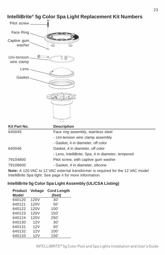
IntelliBrite® 5g Color Spa Light Replacement Kit Numbers
Face Ring
Uni-tensionwire clamp
Lens
Gasket
Pilot screw
Captive gumwasher
Kit Part No. Description640045 Face ring assembly, stainless steel
- Uni-tension wire clamp assembly
- Gasket, 4 in diameter, off color
640046 Gasket, 4 in diameter, off color
- Lens, IntelliBrite, Spa, 4 in diameter, tempered
79104800 Pilot screw, with captive gum washer
79108600 - Gasket, 4 in diameter, silicone
Note: A 120 VAC to 12 VAC external transformer is required for the 12 VAC modelIntelliBrite Spa light. See page ii for more information.
23
IntelliBrite 5g Color Spa Light Assembly (UL/CSA Listing)
Product Voltage Cord LengthModel (feet)640120 120V 30’640121 120V 50’640122 120V 100’640123 120V 150’640124 120V 250’640130 12V 30’640131 12V 50’640132 12V 100’640133 12V 150’

INTELLIBRITE® itBPool and Spa LED Light Installation and User’s Guide
PENTAIR AQUATIC SYSTEMS1620 HAWKINS AVE., SANFORD, NC 27330 • (919) 566-800010951 WEST LOS ANGELES AVE., MOORPARK, CA 93021 • (805) 553-5000 WWW.PENTAIRPOOL.COMAll Pentair trademarks and logos are owned by Pentair, Inc. Pentair Aquatic Systems™, IntelliBrite®, EasyTouch®, IntelliTouch®, and SunTouch® are trademarks and/or registered trademarks of Pentair Water Pool and Spa, Inc. and/or its affiliated companies in the United States and/ or other countries. Unless expressly noted, names and brands of third parties that may be used in this document are not used to indicate an affiliation or endorsement between the owners of these names and brands and Pentair Water Pool and Spa, Inc. Those names and brands may be the trademarks or registered trademarks of those third parties. Because we are continuously improving our products and services, Pentair reserves the right to change specifications without prior notice. Pentair is an equal opportunity employer.© 2013 Pentair Aquatic Systems. All rights reserved. This document is subject to change without notice.
P/N 619827 REV. E 6/13
*619827*