inteligennt, intelisysnt...nt family controllers (ig-nt, ig-ntc, is-nt-bb, is-ntc-bb, im-nt and...
TRANSCRIPT

Output Ratings
Voltage, Frequency Prime Standby
400/230 V, 50 HzkVA 650 715
kW 520 572
kVA
kW
Ratings at 0.8 power factor. Please refer to the output ratings technical data section for specific generator set outputs per voltage.
Dimensions and WeightsLength mm 3900 (153.5)
Width mm 1461 (57.5)
Height mm 2156 (84.9)
Weight (Dry) kg 4454 (9819)
Weight (Wet) kg 4522 (9969)
Ratings in accordance with ISO 8528, ISO 3046, IEC 60034, BS5000 and NEMA MG-1.22.
Generator set pictured may include optional accessories.
Prime Rating
These ratings are applicable for supplying continuous electrical power (at variable load) in lieu of commercially purchased power. There is no limitation to the annual hours of operation and this model can supply 10% overload power for 1 hour in 12 hours.
Standby RatingThese ratings are applicable for supplying continuous electrical power (at variable load) in the event of a utility power failure. No overload is permitted on these ratings. The alternator on this model is peak continuous rated (as defined in ISO 8528-3).
Standard Reference ConditionsNote: Standard reference conditions 25°C (77°F) Air Inlet Temp, 100m (328 ft) A.S.L. 30% relative humidity. Fuel consumption data at full load with diesel fuel with specific gravity of 0.85 and conforming to BS2869: 1998, Class A2.
FG Wilson offer a range of optional features to allow you to tailor our generator sets to meet your power needs. Options available include:
• Upgrade to CE Certification
• A wide range of Sound Attenuated Enclosures
• A variety of generator set control and synchronising panels
• Additional alarms and shutdowns
• A selection of exhaust silencer noise levels
For further information on all of the standard and optional features accompanying this product please contact your local Dealer or visit:
www.fgwilson.com
#DEALER_LOGO
P715-3
#FGWILSON_GENSET_IMAGE
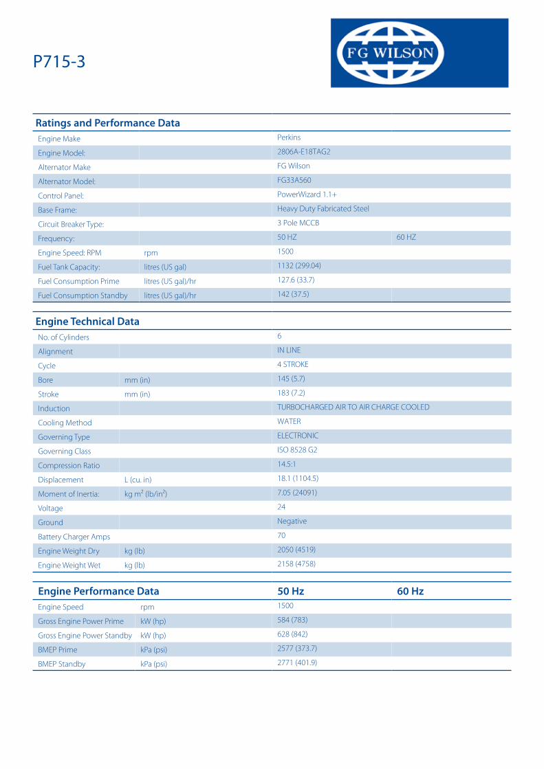
Ratings and Performance DataEngine Make Perkins
Engine Model: 2806A-E18TAG2
Alternator Make FG Wilson
Alternator Model: FG33A560
Control Panel: PowerWizard 1.1+
Base Frame: Heavy Duty Fabricated Steel
Circuit Breaker Type: 3 Pole MCCB
Frequency: 50 HZ 60 HZ
Engine Speed: RPM rpm 1500
Fuel Tank Capacity: litres (US gal) 1132 (299.04)
Fuel Consumption Prime litres (US gal)/hr 127.6 (33.7)
Fuel Consumption Standby litres (US gal)/hr 142 (37.5)
Engine Technical DataNo. of Cylinders 6
Alignment IN LINE
Cycle 4 STROKE
Bore mm (in) 145 (5.7)
Stroke mm (in) 183 (7.2)
Induction TURBOCHARGED AIR TO AIR CHARGE COOLED
Cooling Method WATER
Governing Type ELECTRONIC
Governing Class ISO 8528 G2
Compression Ratio 14.5:1
Displacement L (cu. in) 18.1 (1104.5)
Moment of Inertia: kg m² (lb/in²) 7.05 (24091)
Voltage 24
Ground Negative
Battery Charger Amps 70
Engine Weight Dry kg (lb) 2050 (4519)
Engine Weight Wet kg (lb) 2158 (4758)
Engine Performance Data 50 Hz 60 HzEngine Speed rpm 1500
Gross Engine Power Prime kW (hp) 584 (783)
Gross Engine Power Standby kW (hp) 628 (842)
BMEP Prime kPa (psi) 2577 (373.7)
BMEP Standby kPa (psi) 2771 (401.9)
P715-3
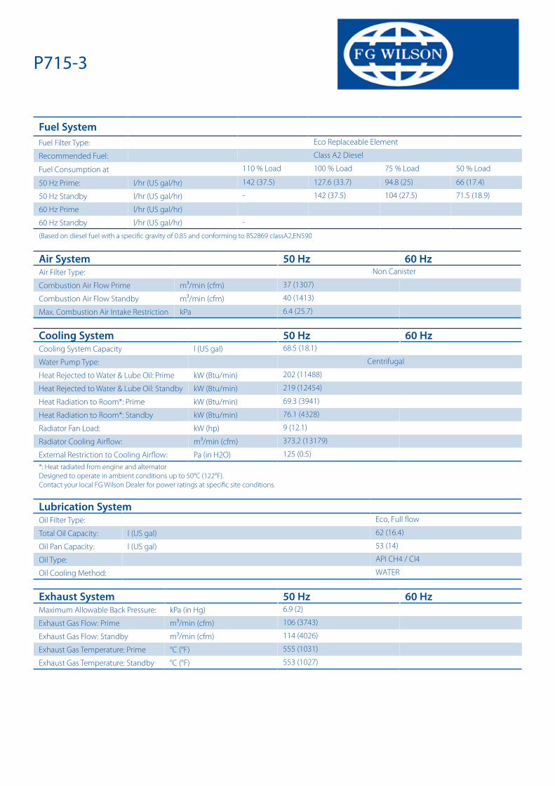
Fuel SystemFuel Filter Type: Eco Replaceable Element
Recommended Fuel: Class A2 Diesel
Fuel Consumption at 110 % Load 100 % Load 75 % Load 50 % Load
50 Hz Prime: l/hr (US gal/hr) 142 (37.5) 127.6 (33.7) 94.8 (25) 66 (17.4)
50 Hz Standby l/hr (US gal/hr) - 142 (37.5) 104 (27.5) 71.5 (18.9)
60 Hz Prime l/hr (US gal/hr)
60 Hz Standby l/hr (US gal/hr) -
(Based on diesel fuel with a specific gravity of 0.85 and conforming to BS2869 classA2,EN590
Air System 50 Hz 60 HzAir Filter Type: Non Canister
Combustion Air Flow Prime m³/min (cfm) 37 (1307)
Combustion Air Flow Standby m³/min (cfm) 40 (1413)
Max. Combustion Air Intake Restriction kPa 6.4 (25.7)
Cooling System 50 Hz 60 HzCooling System Capacity l (US gal) 68.5 (18.1)
Water Pump Type: Centrifugal
Heat Rejected to Water & Lube Oil: Prime kW (Btu/min) 202 (11488)
Heat Rejected to Water & Lube Oil: Standby kW (Btu/min) 219 (12454)
Heat Radiation to Room*: Prime kW (Btu/min) 69.3 (3941)
Heat Radiation to Room*: Standby kW (Btu/min) 76.1 (4328)
Radiator Fan Load: kW (hp) 9 (12.1)
Radiator Cooling Airflow: m³/min (cfm) 373.2 (13179)
External Restriction to Cooling Airflow: Pa (in H2O) 125 (0.5)*: Heat radiated from engine and alternatorDesigned to operate in ambient conditions up to 50°C (122°F).Contact your local FG Wilson Dealer for power ratings at specific site conditions.
Lubrication SystemOil Filter Type: Eco, Full flow
Total Oil Capacity: l (US gal) 62 (16.4)
Oil Pan Capacity: l (US gal) 53 (14)
Oil Type: API CH4 / CI4
Oil Cooling Method: WATER
Exhaust System 50 Hz 60 HzMaximum Allowable Back Pressure: kPa (in Hg) 6.9 (2)
Exhaust Gas Flow: Prime m³/min (cfm) 106 (3743)
Exhaust Gas Flow: Standby m³/min (cfm) 114 (4026)
Exhaust Gas Temperature: Prime °C (°F) 555 (1031)
Exhaust Gas Temperature: Standby °C (°F) 553 (1027)
P715-3

Alternator Physical DataNo. of Bearings: 1
Insulation Class: H
Winding Pitch: 2/3
Winding Code R16
Wires: 6
Ingress Protection Rating: IP21
Excitation System: SHUNT
AVR Model: A106 MKII
* dependant on voltage code selected
Alternator Operating DataOverspeed: rpm 2250
Voltage Regulation: (Steady state) % +/- 1.0
Wave Form NEMA = TIF: 50
Wave Form IEC = THF: % 2
Total Harmonic content LL/LN: % 3
Radio Interference: EN61000-6
Radiant Heat: 50 Hz kW (Btu/min) 31.1 (1769)
Radiant Heat: 60 Hz kW (Btu/min)
Alternator Performance Data 50 Hz:
Voltage Code
415/240 V 400/230 V 380/220 V
230 V
Motor Starting Capability* kVA 1763 1650 1488
Short Circuit Capacity** % 300 300 300 300
Reactances Xd 2.327 2.504 2.775
X’d 0.106 0.114 0.126
X”d 0.089 0.089 0.099
Alternator Performance Data 60 Hz
Voltage Code
Motor Starting Capability* kVA
Short Circuit Capacity** % 300 300 300 300 300
Reactances Xd
X’d
X”d
Reactances shown are applicable to prime ratings.
*Based on 30% voltage dip at 0.4 power factor.
** With optional independant excitation system (PMG / AUX winding)
P715-3
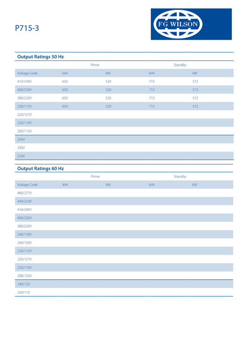
Output Ratings 50 HzPrime Standby
Voltage Code kVA kW kVA kW
415/240V 650 520 715 572
400/230V 650 520 715 572
380/220V 650 520 715 572
230/115V 650 520 715 572
220/127V
220/110V
200/115V
240V
230V
220V
Output Ratings 60 HzPrime Standby
Voltage Code kVA kW kVA kW
480/277V
440/254V
416/240V
400/230V
380/220V
240/139V
240/120V
230/115V
220/127V
220/110V
208/120V
240/120
220/110
P715-3

#FGWILSON_GENSET_IMAGE
#DEALER_LOGO
DocumentationOperation and maintenance manual including circuit wiring diagrams.
Generator Set StandardsThe equipment meets the following standards: BS5000, ISO 8528, ISO 3046, IEC 60034, NEMA MG-1.22.
Warranty6.8 – 750 kVA electric power generation products in prime applications the warranty period is 12 months from date of start-up, unlimited hours (8760). For standby applications the warranty period is 24 months from date of start-up, limited to 500 hours per year.
730 – 2500 kVA electric power generation products in prime applications the warranty period is 12 months from date of start-up, unlimited hours (8760 hours) or 24 months from date of start-up, limited to 6000 hours. For standby applications the warranty period is 36 months from date of start-up, limited to 500 hours per year.
FG Wilson manufactures product in the following locations:Northern Ireland • Brazil • China • IndiaWith headquarters in Northern Ireland, FG Wilson operates through a Global Dealer Network.To contact your local Sales Office please visit the FG Wilson website at www.fgwilson.com.
FG Wilson is a trading name of Caterpillar (NI) Limited.
In line with our policy of continuous product development, we reserve the right to change specification without notice. 2019-08-23
P715-3
Dealer Contact Details

Copyright © 2006 ComAp, spol. s r.o. Written by Pavel Mareš Prague, Czech Republic
ComAp a.s. Kundratka 2359/17, 180 00 Praha 8, Czech Republic Tel: +420 246 012 111, Fax: +266 31 66 47 E-mail: [email protected], www.comap.cz
InteliGenNT, InteliSysNT �
Operator Guide
InteliVision 5, InteliVision 8
InteliVision 5, InteliVision 8 – Operator guide, ©ComAp – May 2013 IGS-NT Operator Guide 05-2013.pdf
2
Table of Contents Table of Contents................................................................................................................................2 General guidelines ..............................................................................................................................3
Description of the controller system .................................................................................................3 Conformity declaration ....................................................................................................................3 !! Warnings !! ..................................................................................................................................3 Dangerous voltage ..........................................................................................................................4 Adjust set points .............................................................................................................................4 Adjust set points .............................................................................................................................4
Available related documentation..........................................................................................................5 InteliVision 5 .......................................................................................................................................5
Page Structure ................................................................................................................................9 Connection ................................................................................................................................... 10 Alarms .......................................................................................................................................... 10 Setpoint Change ........................................................................................................................... 12 Entering the Password .................................................................................................................. 13 History .......................................................................................................................................... 18 Display Contrast Adjustment ......................................................................................................... 18 Controller Information Screen ....................................................................................................... 19
InteliVision 8 ..................................................................................................................................... 20 Page Structure .............................................................................................................................. 25 Connection ................................................................................................................................... 26 Alarms .......................................................................................................................................... 27 Setpoint Change ........................................................................................................................... 29 Entering the password .................................................................................................................. 32 History .......................................................................................................................................... 33 Display Contrast Adjustment ......................................................................................................... 34 Controller Information Screen ....................................................................................................... 36
List of abbreviations .......................................................................................................................... 37

InteliVision 5, InteliVision 8 – Operator guide, ©ComAp – May 2013 IGS-NT Operator Guide 05-2013.pdf
3
General guidelines This manual provides general information on how to operate the IG/IS-NT controller via InteliVision 5 or InteliVision 8. This manual is intended for everybody who is concerned with operation and maintenance of the gen-set.
Description of the controller system NT family controllers are comprehensive AMF-controllers for single and multiple generating sets operating in stand-by or parallel modes. Synchronizer, isochronous load sharer, Mains and Generator protections allow for a total integrated solution for gen-sets in stand-by and parallel modes with multiple engine support. NT family controllers (IG-NT, IG-NTC, IS-NT-BB, IS-NTC-BB, IM-NT and IM-NT-BB) could be equipped with a powerful colour display showing icons, symbols and bar-graphs for intuitive operation, which sets, together with high functionality, new standards in gen-set controls. The controller automatically starts the gen-set, closes the gen-set C.B. when all conditions are met, then stops the engine on external signal or by pressing push buttons. Parallel to Mains operation can be achieved without additional HW. Forward and reverse synchronizing, Mains protection including vector shift, load and power factor control, earth fault protection are the major functions provided. Interfacing to foreign synchronizers and load sharers is supported. The key feature of NT family controllers is their easy-to-use installation and operation. Predefined configurations for typical applications are available as well as user-defined configurations for special applications.
Conformity declaration
Following described machine complies with the appropriate basic safety and health requirement of the EC Low Voltage Directive 2006/95/EC and EC Electromagnetic Compatibility Directive 2004/108/EEC based on its design and type, as brought into circulation by us.
Note: ComAp believes that all information provided herein is correct and reliable and reserves the right to update at any time. ComAp does not assume any responsibility for its use unless otherwise expressly undertaken.
!! Warnings !! Be aware that the binary outputs can change state during and after software reprogramming (before the controller is used again ensure that the proper
configuration and setpoint settings are set in the controller)!!!
Be aware that gen-set can automatically or remotely start when following

InteliVision 5, InteliVision 8 – Operator guide, ©ComAp – May 2013 IGS-NT Operator Guide 05-2013.pdf
4
controller terminals are disconnected !!! x Mains voltage measuring and / or x Binary outputs for MCB control and / or x MCB feedback
Switch InteliGenNT to OFF mode and disconnect the Binary outputs Starter and Fuel
to avoid unexpected automatic start of gen-set and GCB closing.
!!! CAUTION !!! Dangerous voltage In no case touch the terminals for voltage and current measurement! Always properly connect grounding terminals! Take care when disconnecting In/Im3 terminals when the gen-set is stopped. For safety connect parallel to controller In/Im3 terminals two anti parallel diodes 10A/100V. In any case do not disconnect generator CT terminals when the gen-set is loaded.
Adjust set points All setpoints are preadjusted to their typical values. But the setpoints in the “Basic settings” settings group !!must!! be adjusted before the first startup of the gen-set.
!!! WRONG ADJUSTMENT OF BASIC PARAMETERS CAN DESTROY THE GEN-SET !!!
The following instructions are for qualified personnel only.
To avoid personal injury do not perform any action not specified in this User guide !!!
Adjust set points All parameters are preadjusted to their typical values. But the set points in the “Basic settings” settings group !!must!! be adjusted before the first startup of the gen-set.
!!! WRONG ADJUSTMENT OF BASIC PARAMETERS CAN DESTROY THE GEN-SET !!!
The following instructions are for qualified personnel only.
To avoid personal injury do not perform any action not specified in this User guide !!!
InteliVision 5, InteliVision 8 – Operator guide, ©ComAp – May 2013 IGS-NT Operator Guide 05-2013.pdf
5
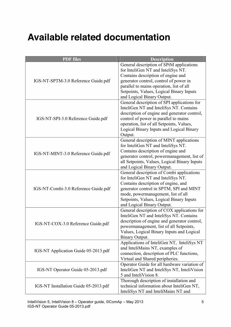
Available related documentation
PDF files Description
IGS-NT-SPTM-3.0 Reference Guide.pdf
General description of SPtM applications for InteliGen NT and InteliSys NT. Contains description of engine and generator control, control of power in parallel to mains operation, list of all Setpoints, Values, Logical Binary Inputs and Logical Binary Output.
IGS-NT-SPI-3.0 Reference Guide.pdf
General description of SPI applications for InteliGen NT and InteliSys NT. Contains description of engine and generator control, control of power in parallel to mains operation, list of all Setpoints, Values, Logical Binary Inputs and Logical Binary Output.
IGS-NT-MINT-3.0 Reference Guide.pdf
General description of MINT applications for InteliGen NT and InteliSys NT. Contains description of engine and generator control, powermanagement, list of all Setpoints, Values, Logical Binary Inputs and Logical Binary Output.
IGS-NT-Combi-3.0 Reference Guide.pdf
General description of Combi applications for InteliGen NT and InteliSys NT. Contains description of engine, and generator control in SPTM, SPI and MINT mode, powermanagement, list of all Setpoints, Values, Logical Binary Inputs and Logical Binary Output.
IGS-NT-COX-3.0 Reference Guide.pdf
General description of COX applications for InteliGen NT and InteliSys NT. Contains description of engine and generator control, powermanagement, list of all Setpoints, Values, Logical Binary Inputs and Logical Binary Output.
IGS-NT Application Guide 05-2013.pdf
Applications of InteliGen NT, InteliSys NT and InteliMains NT, examples of connection, description of PLC functions, Virtual and Shared peripheries.
IGS-NT Operator Guide 05-2013.pdf Operator Guide for all hardware variation of InteliGen NT and InteliSys NT, InteliVision 5 and InteliVision 8.
IGS-NT Installation Guide 05-2013.pdf Thorough description of installation and technical information about InteliGen NT, InteliSys NT and InteliMains NT and

InteliVision 5, InteliVision 8 – Operator guide, ©ComAp – May 2013 IGS-NT Operator Guide 05-2013.pdf
6
related accessories.
IGS-NT Communication Guide 05-2013.pdf
Thorough description of connectivity and communication for InteliGen NT, InteliSys NT and InteliMains NT and related accessories.
IGS-NT Troubleshooting Guide 05-2013.pdf How to solve most common troubles with InteliGen NT and InteliSys NT controllers. Including the list of alarm massages.
IGS-NT & ID-DCU Accessory Modules 05-2013.pdf
Thorough description of accessory modules for IGS-NT family, technical data, information about installation of the modules, how to connect them to controller and set them properly.

InteliVision 5, InteliVision 8 – Operator guide, ©ComAp – May 2013 IGS-NT Operator Guide 05-2013.pdf
7
InteliVision 5
1
2
3
4
5
14
13
12
11
6785910
15
INTELIVISION 5 INDICATION POSITION DESCRIPTION
1 Status LED indication. The InteliVision 5 is running. DISPLAY AND CONTROL BUTTONS POSITION BUTTON DESCRIPTION
2
Up button. Use this button to move up, scroll up the screens or increase a value.
3
Menu button. Use this button to switch to menu subpages. See Pages Structure chapter below this table for more details.
4
Enter button. Use this button to enter item from the list, menu, or confirm a value.
5
Down button. Use this button to move down, scroll down the screens or decrease a value.

InteliVision 5, InteliVision 8 – Operator guide, ©ComAp – May 2013 IGS-NT Operator Guide 05-2013.pdf
8
CONTEXT SENSITIVE BUTTONS POSITION INDICATOR DESCRIPTION
6 Mode button. Use this button to call mode change.*
7 History button. Use this button to call controller history screen.*
8 Alarm list button. Use this button to enter Alarm list.*
9 GCB button. Works in MAN mode only. Press this button to open or close the GCB manually. Note that certain conditions must be valid otherwise GCB closing is blocked.*
10
MCB button. Works in MAN mode only. Press this button to open or close the MCB manually.* CAUTION! You can disconnect the load from the mains supply with this button! Be sure you know well what you are about to do!
* - It is valid in default configuration only. Screens description and buttons 6 to 10 could have different meaning in customized versions or SW branches. GEN-SET CONTROL BUTTONS AND DISPLAY POSITION BUTTON DESCRIPTION
11
Stop button. Works in MAN and SEM mode only. Press this button to initiate the stop sequence of the gen-set. Repeated pressing or holding the button for more than 2s will cancel current phase of stop sequence (like ramping the power down or cooling) and next phase will continue.
12
Fault reset button. Use this button to acknowledge alarms and deactivate the horn output. Inactive alarms will disappear immediately and status of active alarms will be changed to “confirmed” so they will disappear as soon as their reasons dismiss.
13 Horn rest button. Use this button to deactivate the horn output without acknowledging the alarms.
14 Start button. Works in MAN and SEM mode only. Press this button to initiate the start sequence of the engine.
15 Colour display, 320x240 pixels.

InteliVision 5, InteliVision 8 – Operator guide, ©ComAp – May 2013 IGS-NT Operator Guide 05-2013.pdf
9
Page Structure Display Screens and Pages Structure The displayed information is structured into "pages" and "screens". 1. The pages Metering consists of screens which displays measured values like voltages, current, oil pressure etc., computed values like i.e. gen-set power, statistic data and etc.. Use arrows Up and Down buttons to switch over the pages. 2. The Setpoints screen contains all setpoints organized to groups and also a special group for entering password. 3. The History screen shows the history log in the order that the last record is displayed first. 4. Help/Others screen allows set-up languages, user access, InteliVision 5 setting and etc..
+
+
+
+
Metering Setpoints
Menu AlarmList
History
Help/Othhers

InteliVision 5, InteliVision 8 – Operator guide, ©ComAp – May 2013 IGS-NT Operator Guide 05-2013.pdf
10
Connection
Alarms Alarms are structured into two levels and inteliVision 5 allows easy interpreted their meaning based on the colour scheme. First level alarm (yellow lamp, warnings) is
interpreted with yellow colour . Red colour is used for all second level alarms (Red lamp, ShutDown,…). When an error occurs, a new alarm appears in the AlarmList screen, exclamation mark starts blinking on the metering screens.
Hint: When a new alarm appears AlarmList screen is displayed automatically when the main/first Metering screen is displayed. From different screen, Alarm button has to be used to display AlarmList screen.
Alarm indication
Second level alarm
First level alarm
Direct button to AlarmList
Configuration reading
InteliVision 5 information SW, HW version and release date

InteliVision 5, InteliVision 8 – Operator guide, ©ComAp – May 2013 IGS-NT Operator Guide 05-2013.pdf
11
AlarmList Screen
Alarm activated with analogue value
Alarm activated with binary inputs
Number of active alarms
Sum of unacknowledged active and inactive alarms
Sum of all alarms
Second level alarm
First level alarm
Second level alarm
First level alarm
Active ECU alarm
Inactive unacknowledged first level alarm Active unacknowledged first level alarm
Inactive unacknowledged second level alarm Active unacknowledged second level alarm

InteliVision 5, InteliVision 8 – Operator guide, ©ComAp – May 2013 IGS-NT Operator Guide 05-2013.pdf
12
Setpoint Change
+
Hint: Setpoints marked with a padlock icon are password protected. Enter password as described in the chapter Entering the Password below.

InteliVision 5, InteliVision 8 – Operator guide, ©ComAp – May 2013 IGS-NT Operator Guide 05-2013.pdf
13
Entering the Password
+
Locked Display and Setpoints
Hint: Log in? Password dialog has to be open and then use o or m for position and for the field use n or p. Password is a five-digit number (0 - 65535). Only setpoints associated with the entered password level can be modified. Display is locked automatically when no action is done within 15 minutes.
Locked setpoint
Display is locked, no user is logged in

InteliVision 5, InteliVision 8 – Operator guide, ©ComAp – May 2013 IGS-NT Operator Guide 05-2013.pdf
14
Hint: Break through password prottection - Break through password function can be ENABLED/DISABLED from the
password management window in InteliMonitor (initial status is DISABLED). - Warning “PassInsertBlck” appears in alarm list when controller is blocked - It is not allowed to insert the password in case that controller is blocked. There
is information that controller is blocked for next password attempt and time remaining till the end of blocation instead of password input window at the terminal screen.
- The controller is locked for 5 minutes when the password is 6 times wrong entered (in case of next 6 wrong attempts (correct password was not inserted at all) for 30, 60, 120, 240 minutes). Incorrect password message appears in the history of the controller when the invalid password is used.
Unlocked Display and Setpoints
For setpoints change use arrows n or p to go to a certain setpoint (e.g. Base load) and press Enter button, see pictures below:
Numeric Setpoint Change
Display is unlocked, an user is logged in
Unlocked setpoint
Min ... Max value
Actual cursor position
Actual setpoint value
Cursor position - Arrow right Cursor position - Arrow left

InteliVision 5, InteliVision 8 – Operator guide, ©ComAp – May 2013 IGS-NT Operator Guide 05-2013.pdf
15
Use o or m buttons to go to a certain position of the field and use n or p buttons to change the value. Then use Enter button to confirm new value. Hint: If you set the value out of limit, the field will get red colour and the new value is invalid. Invalid value cannot be confirmed.
InteliVision 5, InteliVision 8 – Operator guide, ©ComAp – May 2013 IGS-NT Operator Guide 05-2013.pdf
16
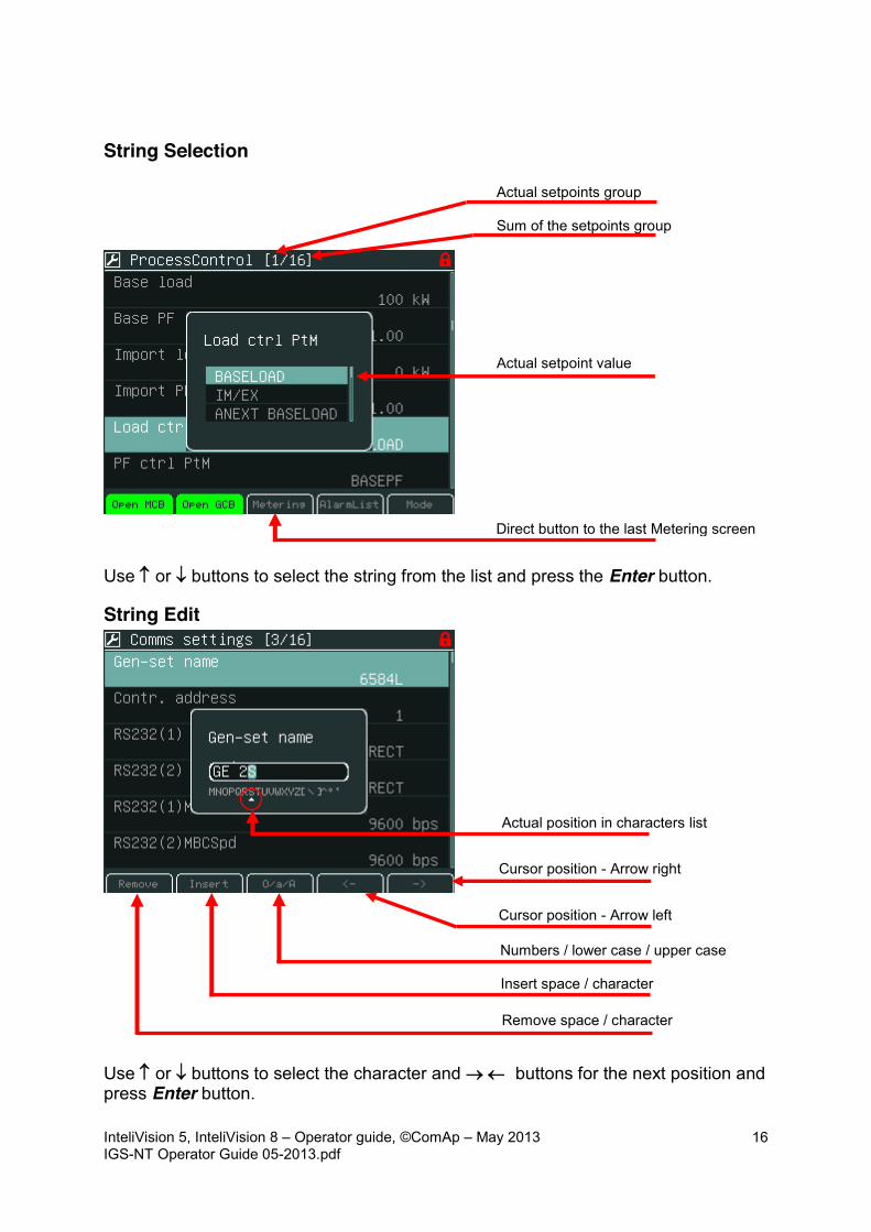
String Selection
Use n or p buttons to select the string from the list and press the Enter button.
String Edit
Use n or p buttons to select the character and o m buttons for the next position and press Enter button.
Actual setpoint value
Sum of the setpoints group
Actual position in characters list
Actual setpoints group
Cursor position - Arrow right Cursor position - Arrow left
Numbers / lower case / upper case
Insert space / character
Remove space / character
Direct button to the last Metering screen

InteliVision 5, InteliVision 8 – Operator guide, ©ComAp – May 2013 IGS-NT Operator Guide 05-2013.pdf
17
Time and Date Edit
Use n p buttons to select the number, o m for the next position and press Enter button.
Combined Setpoints
Use n or p buttons to select the number, o or m for the next position or go Up or go Down context buttons and press Enter button.
Scroll bar shows cursor position on the current screen
Cursor position - Arrow right Cursor position - Arrow left
Cursor position - Arrow right Cursor position - Arrow left
Actual setpoint value

InteliVision 5, InteliVision 8 – Operator guide, ©ComAp – May 2013 IGS-NT Operator Guide 05-2013.pdf
18
History
History page
Display Contrast Adjustment Display brightness could be set from the keyboard with button combination Menu button and n or p.
Two modes for backlight could be used day or night mode. Hold Menu button until the day or night pictogram appears.
Hold
Press
Or press
Direct button to the last Metering screen
Direct button to the first position / or column In the history log
Page scroll (1x, 1x Page, 10x Page)
Scroll history log - Arrow right
Scroll history log - Arrow left

InteliVision 5, InteliVision 8 – Operator guide, ©ComAp – May 2013 IGS-NT Operator Guide 05-2013.pdf
19
Hint: Display backlight could be switched off due to Backlight Time. For recovery any button has to be pressed. (see IV5 Settings).
Controller Information Screen
Hint: Lost password? Display the information screen containing the serial number and password decode number as described in the picture bellow and send them to your local distributor.
Serial number
Password decode
Day mode - active Night mode - inactive
InteliVision 5, InteliVision 8 – Operator guide, ©ComAp – May 2013 IGS-NT Operator Guide 05-2013.pdf
20
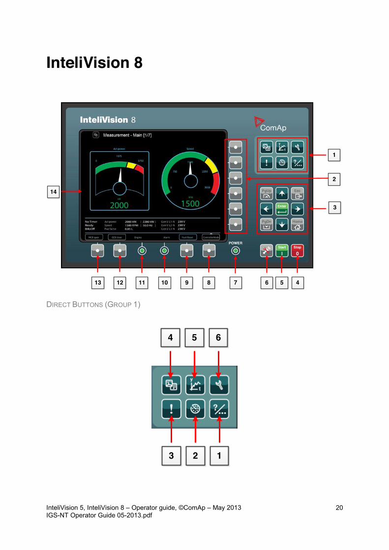
InteliVision 8
2
1
3
45678910111213
14
DIRECT BUTTONS (GROUP 1)
123
654

InteliVision 5, InteliVision 8 – Operator guide, ©ComAp – May 2013 IGS-NT Operator Guide 05-2013.pdf
21
POSITION BUTTON DESCRIPTION
1
Help/Others - settings and information (users/passwords, communication, languages, InteliVision 8 and controller info, InteliVision 8 settings)
2
History button. Use this button to call controller history.
3
Alarm list button. Use this button to enter AlarmList.
4
Measurement button. Display actual values (power, synchro, analog. inputs, binary I/O, cylinders, engines, etc.)
5
Trends button. Use this button to go to the trends screen where chosen values in graphs/real time trends are displayed.
6
Setpoints button. Use to go to the setpoints group screen.
CONTEXT SENSITIVE BUTTONS (GROUP 2)
The context sensitive buttons allow display predefined screens when a suitable button is pressed. Meaning of the buttons depends on the Main menu option that is currently displayed (Metering, Trends and etc.) and on the controller firmware. The Picture above introduces standard SW IGS-NT-2.5.
InteliVision 5, InteliVision 8 – Operator guide, ©ComAp – May 2013 IGS-NT Operator Guide 05-2013.pdf
22
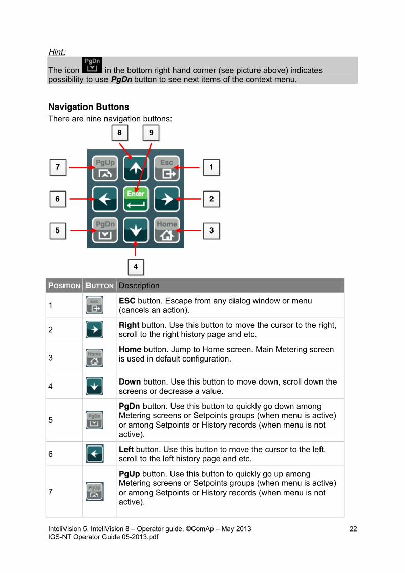
Hint:
The icon in the bottom right hand corner (see picture above) indicates possibility to use PgDn button to see next items of the context menu.
Navigation Buttons There are nine navigation buttons:
1
2
4
3
7
6
5
8 9
POSITION BUTTON Description
1
ESC button. Escape from any dialog window or menu (cancels an action).
2
Right button. Use this button to move the cursor to the right, scroll to the right history page and etc.
3
Home button. Jump to Home screen. Main Metering screen is used in default configuration.
4
Down button. Use this button to move down, scroll down the screens or decrease a value.
5
PgDn button. Use this button to quickly go down among Metering screens or Setpoints groups (when menu is active) or among Setpoints or History records (when menu is not active).
6
Left button. Use this button to move the cursor to the left, scroll to the left history page and etc.
7
PgUp button. Use this button to quickly go up among Metering screens or Setpoints groups (when menu is active) or among Setpoints or History records (when menu is not active).
InteliVision 5, InteliVision 8 – Operator guide, ©ComAp – May 2013 IGS-NT Operator Guide 05-2013.pdf
23
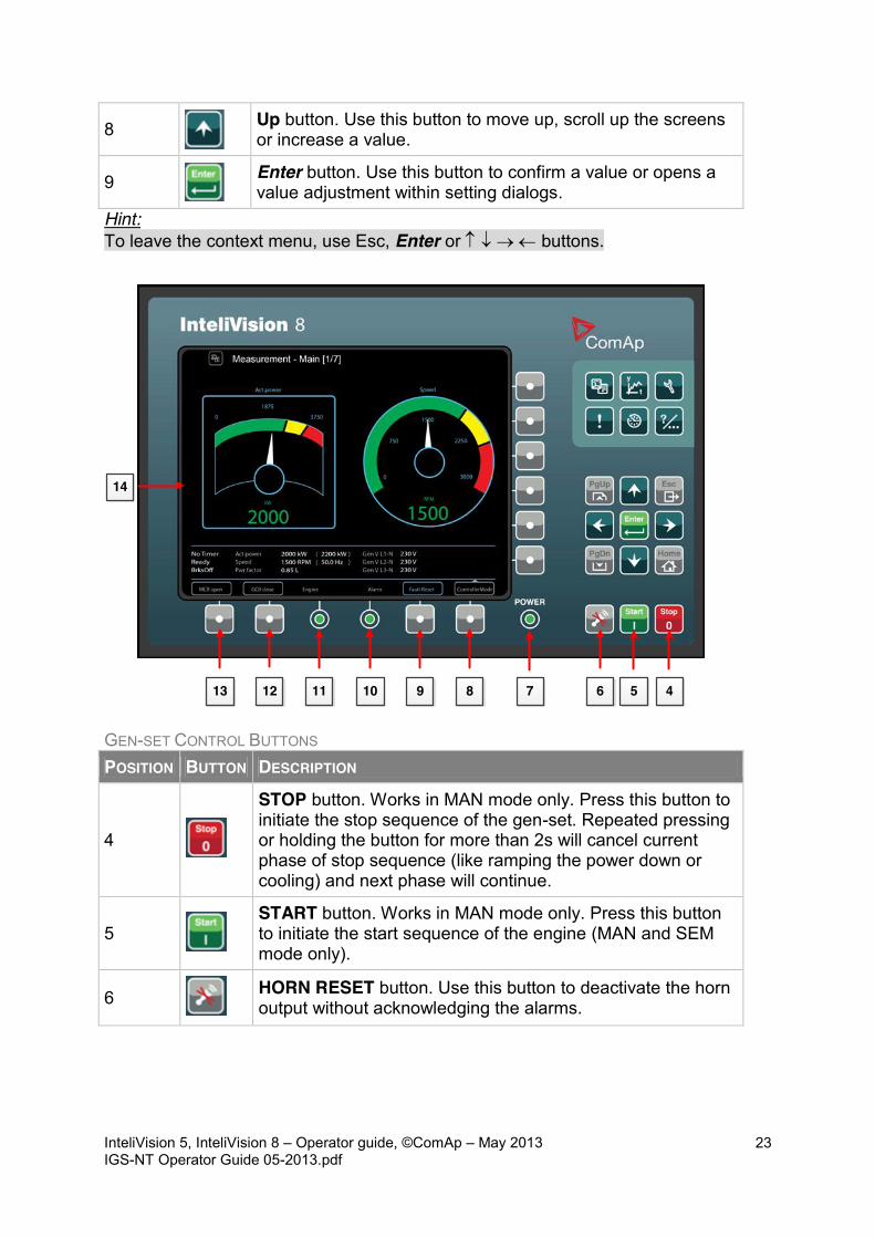
8
Up button. Use this button to move up, scroll up the screens or increase a value.
9
Enter button. Use this button to confirm a value or opens a value adjustment within setting dialogs.
Hint: To leave the context menu, use Esc, Enter or n p o m buttons.
45678910111213
14
GEN-SET CONTROL BUTTONS POSITION BUTTON DESCRIPTION
4
STOP button. Works in MAN mode only. Press this button to initiate the stop sequence of the gen-set. Repeated pressing or holding the button for more than 2s will cancel current phase of stop sequence (like ramping the power down or cooling) and next phase will continue.
5
START button. Works in MAN mode only. Press this button to initiate the start sequence of the engine (MAN and SEM mode only).
6 HORN RESET button. Use this button to deactivate the horn output without acknowledging the alarms.

InteliVision 5, InteliVision 8 – Operator guide, ©ComAp – May 2013 IGS-NT Operator Guide 05-2013.pdf
24
POSITION BUTTON DESCRIPTION
8
Mode button. Use this button to call mode change.*
9
Fault reset button. Use this button to acknowledge alarms and deactivate the horn output. Inactive alarms will disappear immediately and status of active alarms will be changed to “confirmed” so they will disappear as soon as their reasons dismiss.*
12
GCB button. Works in MAN mode only. Press this button to open or close the GCB manually. Note that certain conditions must be valid otherwise GCB closing is blocked.*
13
MCB button. Works in MAN mode only. Press this button to open or close the MCB manually.* CAUTION! You can disconnect the load from the mains supply with this button! Be sure you know well what you are about to do!
14 Colour display, 800x600 pixels. * - It is valid in default SPtM configuration only. Screens description and buttons from 8 to 13 could have different meaning in customized versions or SW branches. INTELIVISION 8 LED INDICATION POSITION DESCRIPTION
7 POWER indication. LED diode turns on when InteliVision 8 is powered up.
10
Alarm indication. Alarm LED indication indicate alarms. Yellow colour for the first level alarms and red colour for the second level alarms. Hint: LED diode blink when at least one acknowledge alarm is present in the Alarm List. LED diode lights when alarms were acknowledged but are still active.
11 Engine indication. Engine LED indication lights only when engine is running.
Hint: When you switch on InteliVision 8 display, Power LED turns on and Engine and Alarm LEDs start to blink for a while.

InteliVision 5, InteliVision 8 – Operator guide, ©ComAp – May 2013 IGS-NT Operator Guide 05-2013.pdf
25
Page Structure Display Screens and Pages Structure The displayed information is structured into "pages" and "screens". 1. The pages Metering consists from pages which displays measured values like voltages, current, oil pressure etc., computed values like i.e. gen-set power, statistic data and etc.. Use arrows Up and Down buttons to switch over the pages. 2. The Setpoints screen contains all setpoints organized into the groups and also a special group for entering password. 3. The History screen shows the history log in the order that the last record is displayed first.
Metering pages structure

InteliVision 5, InteliVision 8 – Operator guide, ©ComAp – May 2013 IGS-NT Operator Guide 05-2013.pdf
26
Connection
Configuration reading
InteliVision 8 core information
Serial number and release date
InteliVision 8 SW and HW version
InteliVision 8 is not connected
Not available value

InteliVision 5, InteliVision 8 – Operator guide, ©ComAp – May 2013 IGS-NT Operator Guide 05-2013.pdf
27
Alarms Alarms are structured into two levels and InteliVision 8 allows easy interpreted their meaning based on the colour scheme. When an error occurs, a new alarm appears in the AlarmList screen, exclamation mark starts blinking on the metering screens. When all alarms are acknowledged, the exclamation stops blinking and is on.
Hint: When a new alarm appears AlarmList screen is displayed automatically when the main/first Metering screen is displayed. From different screen, AlarmList button has to be used to display AlarmList screen.
Alarm indication
Reloaded configuration

InteliVision 5, InteliVision 8 – Operator guide, ©ComAp – May 2013 IGS-NT Operator Guide 05-2013.pdf
28
AlarmList Screen
Hint: Use Fault reset button to confirm alarm in the AlarmList.
Second level alarm
First level alarm
Number of active alarms
Sum of all alarms
Inactive unacknowledged alarm
Active unacknowledged alarm
Active acknowledged alarm
Sum of unacknowledged alarms

InteliVision 5, InteliVision 8 – Operator guide, ©ComAp – May 2013 IGS-NT Operator Guide 05-2013.pdf
29
Setpoint Change On Setpoints screens you can set various setpoints. To go to Setpoints screen press Setpoints button. Setpoints screen appears with the context sensitive buttons for the the setpoints group.
Hint: Content of the context buttons list depends on the type of the application. To be more familiar with setpoints, see Reference Guide of the specific application (e.g.IGS-NT-SPTM-2.5-Reference Guide.pdf or IGS-NT-MINT-2.5-Reference Guide.pdf).
Second level alarm
First level alarm
Setpoints Group
User Access Level
Locked setpoint
Sum of the setpoints group
Order of the setpoints group

InteliVision 5, InteliVision 8 – Operator guide, ©ComAp – May 2013 IGS-NT Operator Guide 05-2013.pdf
30
Change of the Numerical Value Use o, m buttons to go to a certain position of the field and use n p to change the value. Then confirm your settings with Enter button. Hint: If the value is out of limit, the field will color red and the value could not be confirmed.
String Selection Use n p to go to a certain setpoint and press Enter, see picture below:
Actual setpoint value
Cursor position
Min. value
Edited setpoint
Actual setpoint value
Max. value
Administrator signed in

InteliVision 5, InteliVision 8 – Operator guide, ©ComAp – May 2013 IGS-NT Operator Guide 05-2013.pdf
31
String Edit The characters set table appears on the screen when string will be edited (like gen-set name). Use o m and n p to find the position, then press button to confirm text.
Time and Date Edit Date and Time are edited as the numerical value. See Change of the Numerical Value.
Cursor position
Setpoint
Written text
Character table
InteliVision 5, InteliVision 8 – Operator guide, ©ComAp – May 2013 IGS-NT Operator Guide 05-2013.pdf
32
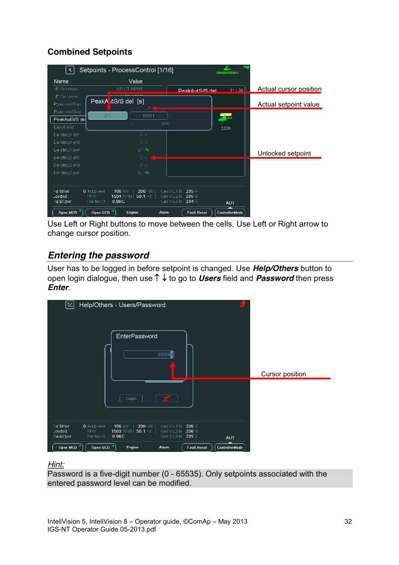
Combined Setpoints
Use Left or Right buttons to move between the cells. Use Left or Right arrow to change cursor position.
Entering the password User has to be logged in before setpoint is changed. Use Help/Others button to open login dialogue, then use n p to go to Users field and Password then press Enter.
Hint: Password is a five-digit number (0 - 65535). Only setpoints associated with the entered password level can be modified.
Unlocked setpoint
Cursor position
Actual cursor position
Actual setpoint value

InteliVision 5, InteliVision 8 – Operator guide, ©ComAp – May 2013 IGS-NT Operator Guide 05-2013.pdf
33
The icons in the top right-hand corner then show you that you are logged on.
History
Displayed values in columns
1
Actual line (row) with the appropriate values in the history log
2
3
4
5
Administrator signed in

InteliVision 5, InteliVision 8 – Operator guide, ©ComAp – May 2013 IGS-NT Operator Guide 05-2013.pdf
34
HISTORY CONTEXT BUTTONS POSITION DESCRIPTION
1 First Row/Col. Use to jump to the first column and first row (the first column is RPM – you cannot move among columns Reason, Date and Time)
2 First Row. Use to jump to the first row.
3 First Col. Use to jump to the first column.
4 Last Col. Use to jump to the last column.
5
PageMode On. Use this button when the PageMode is ON you can use o m buttons to jump by page right or left (quicker
movement through columns). Icon at the top of the screen indicates that PageMode is On.
Display Contrast Adjustment From the mains screen the day or night mode can be choose. The mode is switched when ESC button is pressed for one second. The brightness is adjustable in the full range of 0 % - 100 % in the both modes. The display brightness can be increased/decreased by holding Esc button and repeated pressing n p. See picture below:
Hold
Press
Or press

InteliVision 5, InteliVision 8 – Operator guide, ©ComAp – May 2013 IGS-NT Operator Guide 05-2013.pdf
35
When brightness dialogue is active, use ESC + PgUp buttons or ESC + PgDn to switch between modes, which shall be adjusted.
Hold
Press
Or press
Day mode - active Night mode - inactive
InteliVision 5, InteliVision 8 – Operator guide, ©ComAp – May 2013 IGS-NT Operator Guide 05-2013.pdf
36
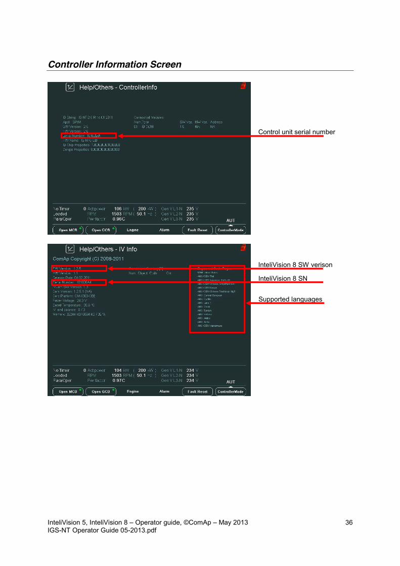
Controller Information Screen
Control unit serial number
InteliVision 8 SW verison
InteliVision 8 SN
Supported languages
InteliVision 5, InteliVision 8 – Operator guide, ©ComAp – May 2013 IGS-NT Operator Guide 05-2013.pdf
37
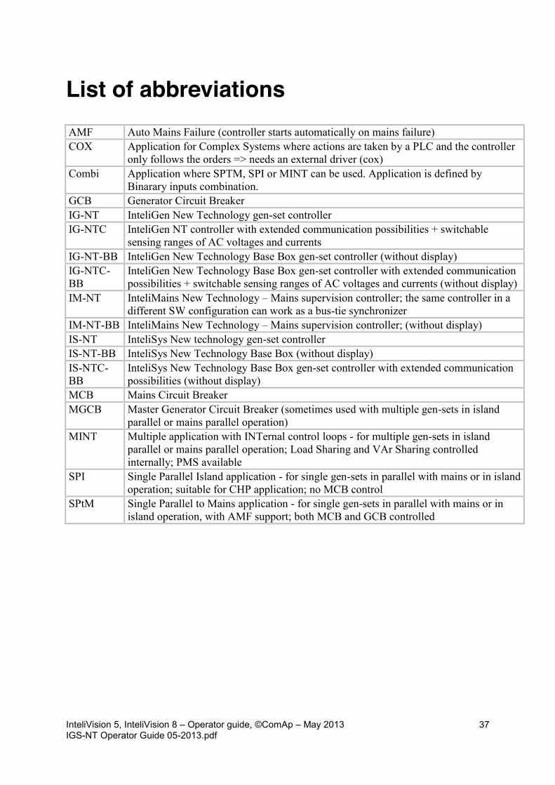
List of abbreviations AMF Auto Mains Failure (controller starts automatically on mains failure) COX Application for Complex Systems where actions are taken by a PLC and the controller
only follows the orders => needs an external driver (cox) Combi Application where SPTM, SPI or MINT can be used. Application is defined by
Binarary inputs combination. GCB Generator Circuit Breaker IG-NT InteliGen New Technology gen-set controller IG-NTC InteliGen NT controller with extended communication possibilities + switchable
sensing ranges of AC voltages and currents IG-NT-BB InteliGen New Technology Base Box gen-set controller (without display) IG-NTC-BB
InteliGen New Technology Base Box gen-set controller with extended communication possibilities + switchable sensing ranges of AC voltages and currents (without display)
IM-NT InteliMains New Technology – Mains supervision controller; the same controller in a different SW configuration can work as a bus-tie synchronizer
IM-NT-BB InteliMains New Technology – Mains supervision controller; (without display) IS-NT InteliSys New technology gen-set controller IS-NT-BB InteliSys New Technology Base Box (without display) IS-NTC-BB
InteliSys New Technology Base Box gen-set controller with extended communication possibilities (without display)
MCB Mains Circuit Breaker MGCB Master Generator Circuit Breaker (sometimes used with multiple gen-sets in island
parallel or mains parallel operation) MINT Multiple application with INTernal control loops - for multiple gen-sets in island
parallel or mains parallel operation; Load Sharing and VAr Sharing controlled internally; PMS available
SPI Single Parallel Island application - for single gen-sets in parallel with mains or in island operation; suitable for CHP application; no MCB control
SPtM Single Parallel to Mains application - for single gen-sets in parallel with mains or in island operation, with AMF support; both MCB and GCB controlled