intelect® neo clinical therapy system user manual neo manual.pdf · intelect® neo clinical...
TRANSCRIPT
Intelect® Neo Clinical Therapy System
User Manual
Operator and Installation
Instructions
6001

1
Intelect® Neo Clinical Therapy System
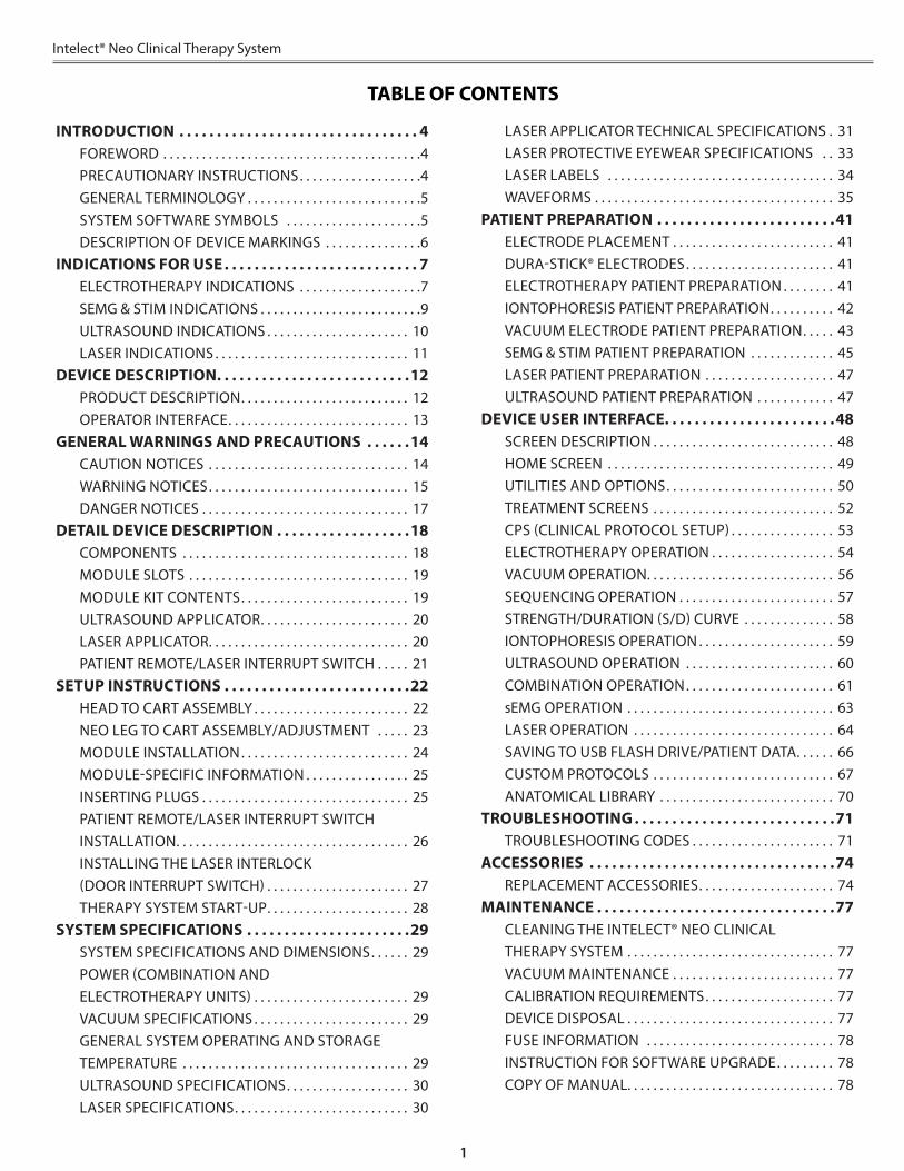
TABLE OF CONTENTS
INTRODUCTION . . . . . . . . . . . . . . . . . . . . . . . . . . . . . . . . 4FOREWORD . . . . . . . . . . . . . . . . . . . . . . . . . . . . . . . . . . . . . . . .4PRECAUTIONARY INSTRUCTIONS . . . . . . . . . . . . . . . . . . .4GENERAL TERMINOLOGY . . . . . . . . . . . . . . . . . . . . . . . . . . .5SYSTEM SOFTWARE SYMBOLS . . . . . . . . . . . . . . . . . . . . .5DESCRIPTION OF DEVICE MARKINGS . . . . . . . . . . . . . . .6
INDICATIONS FOR USE . . . . . . . . . . . . . . . . . . . . . . . . . . 7ELECTROTHERAPY INDICATIONS . . . . . . . . . . . . . . . . . . .7SEMG & STIM INDICATIONS . . . . . . . . . . . . . . . . . . . . . . . . .9ULTRASOUND INDICATIONS . . . . . . . . . . . . . . . . . . . . . . 10LASER INDICATIONS . . . . . . . . . . . . . . . . . . . . . . . . . . . . . . 11
DEVICE DESCRIPTION . . . . . . . . . . . . . . . . . . . . . . . . . .12PRODUCT DESCRIPTION . . . . . . . . . . . . . . . . . . . . . . . . . . 12OPERATOR INTERFACE . . . . . . . . . . . . . . . . . . . . . . . . . . . . 13
GENERAL WARNINGS AND PRECAUTIONS . . . . . .14CAUTION NOTICES . . . . . . . . . . . . . . . . . . . . . . . . . . . . . . . 14WARNING NOTICES . . . . . . . . . . . . . . . . . . . . . . . . . . . . . . . 15DANGER NOTICES . . . . . . . . . . . . . . . . . . . . . . . . . . . . . . . . 17
DETAIL DEVICE DESCRIPTION . . . . . . . . . . . . . . . . . .18COMPONENTS . . . . . . . . . . . . . . . . . . . . . . . . . . . . . . . . . . . 18MODULE SLOTS . . . . . . . . . . . . . . . . . . . . . . . . . . . . . . . . . . 19MODULE KIT CONTENTS . . . . . . . . . . . . . . . . . . . . . . . . . . 19ULTRASOUND APPLICATOR . . . . . . . . . . . . . . . . . . . . . . . 20LASER APPLICATOR . . . . . . . . . . . . . . . . . . . . . . . . . . . . . . . 20PATIENT REMOTE/LASER INTERRUPT SWITCH . . . . . 21
SETUP INSTRUCTIONS . . . . . . . . . . . . . . . . . . . . . . . . .22HEAD TO CART ASSEMBLY . . . . . . . . . . . . . . . . . . . . . . . . 22NEO LEG TO CART ASSEMBLY/ADJUSTMENT . . . . . 23MODULE INSTALLATION . . . . . . . . . . . . . . . . . . . . . . . . . . 24MODULE-SPECIFIC INFORMATION . . . . . . . . . . . . . . . . 25INSERTING PLUGS . . . . . . . . . . . . . . . . . . . . . . . . . . . . . . . . 25PATIENT REMOTE/LASER INTERRUPT SWITCH INSTALLATION . . . . . . . . . . . . . . . . . . . . . . . . . . . . . . . . . . . . 26INSTALLING THE LASER INTERLOCK (DOOR INTERRUPT SWITCH) . . . . . . . . . . . . . . . . . . . . . . 27THERAPY SYSTEM START-UP . . . . . . . . . . . . . . . . . . . . . . 28
SYSTEM SPECIFICATIONS . . . . . . . . . . . . . . . . . . . . . .29SYSTEM SPECIFICATIONS AND DIMENSIONS . . . . . . 29POWER (COMBINATION AND ELECTROTHERAPY UNITS) . . . . . . . . . . . . . . . . . . . . . . . . 29VACUUM SPECIFICATIONS . . . . . . . . . . . . . . . . . . . . . . . . 29GENERAL SYSTEM OPERATING AND STORAGE TEMPERATURE . . . . . . . . . . . . . . . . . . . . . . . . . . . . . . . . . . . 29ULTRASOUND SPECIFICATIONS . . . . . . . . . . . . . . . . . . . 30LASER SPECIFICATIONS . . . . . . . . . . . . . . . . . . . . . . . . . . . 30
LASER APPLICATOR TECHNICAL SPECIFICATIONS . 31LASER PROTECTIVE EYEWEAR SPECIFICATIONS . . 33LASER LABELS . . . . . . . . . . . . . . . . . . . . . . . . . . . . . . . . . . . 34WAVEFORMS . . . . . . . . . . . . . . . . . . . . . . . . . . . . . . . . . . . . . 35
PATIENT PREPARATION . . . . . . . . . . . . . . . . . . . . . . . .41ELECTRODE PLACEMENT . . . . . . . . . . . . . . . . . . . . . . . . . 41DURA-STICK® ELECTRODES . . . . . . . . . . . . . . . . . . . . . . . 41ELECTROTHERAPY PATIENT PREPARATION . . . . . . . . 41IONTOPHORESIS PATIENT PREPARATION . . . . . . . . . . 42VACUUM ELECTRODE PATIENT PREPARATION . . . . . 43SEMG & STIM PATIENT PREPARATION . . . . . . . . . . . . . 45LASER PATIENT PREPARATION . . . . . . . . . . . . . . . . . . . . 47ULTRASOUND PATIENT PREPARATION . . . . . . . . . . . . 47
DEVICE USER INTERFACE . . . . . . . . . . . . . . . . . . . . . . .48SCREEN DESCRIPTION . . . . . . . . . . . . . . . . . . . . . . . . . . . . 48HOME SCREEN . . . . . . . . . . . . . . . . . . . . . . . . . . . . . . . . . . . 49UTILITIES AND OPTIONS . . . . . . . . . . . . . . . . . . . . . . . . . . 50TREATMENT SCREENS . . . . . . . . . . . . . . . . . . . . . . . . . . . . 52CPS (CLINICAL PROTOCOL SETUP) . . . . . . . . . . . . . . . . 53ELECTROTHERAPY OPERATION . . . . . . . . . . . . . . . . . . . 54VACUUM OPERATION . . . . . . . . . . . . . . . . . . . . . . . . . . . . . 56SEQUENCING OPERATION . . . . . . . . . . . . . . . . . . . . . . . . 57STRENGTH/DURATION (S/D) CURVE . . . . . . . . . . . . . . 58IONTOPHORESIS OPERATION . . . . . . . . . . . . . . . . . . . . . 59ULTRASOUND OPERATION . . . . . . . . . . . . . . . . . . . . . . . 60COMBINATION OPERATION . . . . . . . . . . . . . . . . . . . . . . . 61sEMG OPERATION . . . . . . . . . . . . . . . . . . . . . . . . . . . . . . . . 63LASER OPERATION . . . . . . . . . . . . . . . . . . . . . . . . . . . . . . . 64SAVING TO USB FLASH DRIVE/PATIENT DATA . . . . . . 66CUSTOM PROTOCOLS . . . . . . . . . . . . . . . . . . . . . . . . . . . . 67ANATOMICAL LIBRARY . . . . . . . . . . . . . . . . . . . . . . . . . . . 70
TROUBLESHOOTING . . . . . . . . . . . . . . . . . . . . . . . . . . .71TROUBLESHOOTING CODES . . . . . . . . . . . . . . . . . . . . . . 71
ACCESSORIES . . . . . . . . . . . . . . . . . . . . . . . . . . . . . . . . .74REPLACEMENT ACCESSORIES . . . . . . . . . . . . . . . . . . . . . 74
MAINTENANCE . . . . . . . . . . . . . . . . . . . . . . . . . . . . . . . .77CLEANING THE INTELECT® NEO CLINICAL THERAPY SYSTEM . . . . . . . . . . . . . . . . . . . . . . . . . . . . . . . . 77VACUUM MAINTENANCE . . . . . . . . . . . . . . . . . . . . . . . . . 77CALIBRATION REQUIREMENTS . . . . . . . . . . . . . . . . . . . . 77DEVICE DISPOSAL . . . . . . . . . . . . . . . . . . . . . . . . . . . . . . . . 77FUSE INFORMATION . . . . . . . . . . . . . . . . . . . . . . . . . . . . . 78INSTRUCTION FOR SOFTWARE UPGRADE . . . . . . . . . 78COPY OF MANUAL . . . . . . . . . . . . . . . . . . . . . . . . . . . . . . . . 78
2
Intelect® Neo Clinical Therapy System
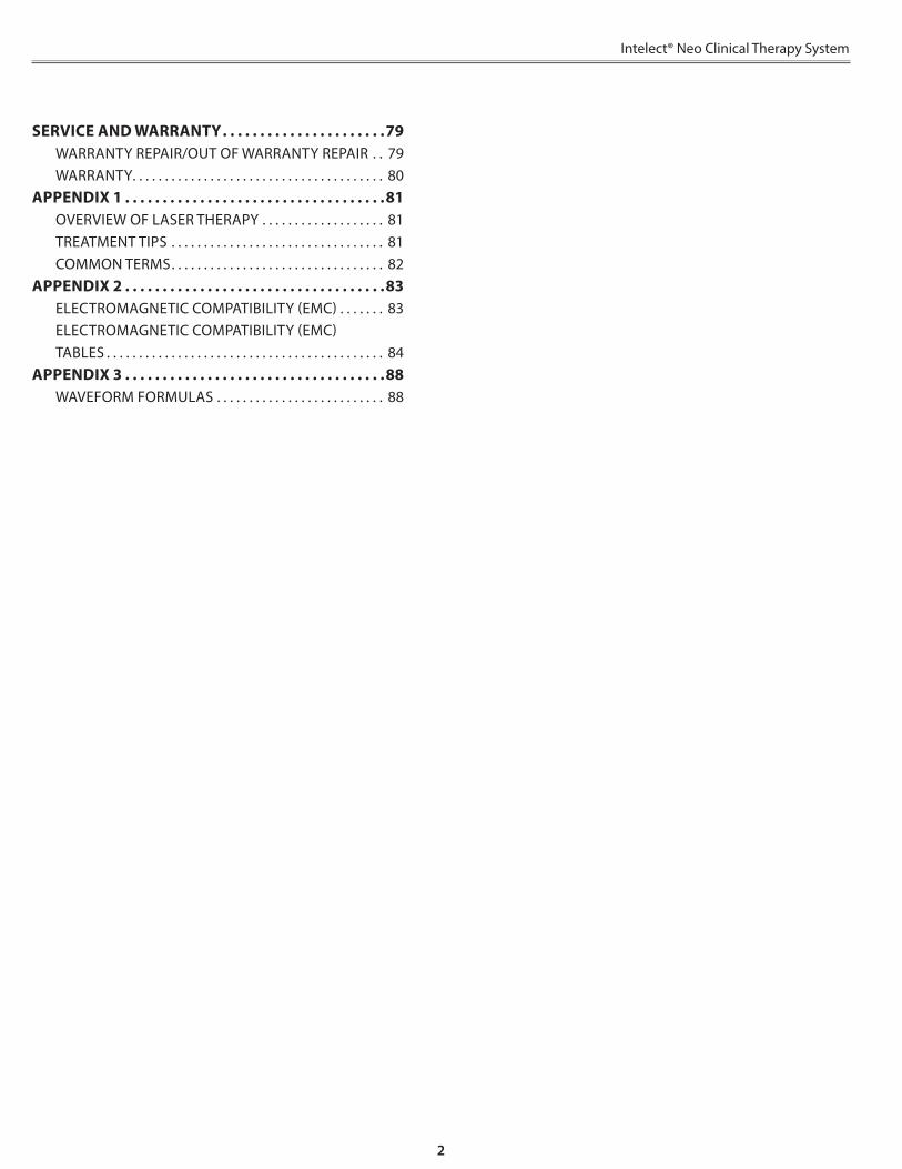
SERVICE AND WARRANTY . . . . . . . . . . . . . . . . . . . . . .79WARRANTY REPAIR/OUT OF WARRANTY REPAIR . . 79WARRANTY . . . . . . . . . . . . . . . . . . . . . . . . . . . . . . . . . . . . . . . 80
APPENDIX 1 . . . . . . . . . . . . . . . . . . . . . . . . . . . . . . . . . . .81OVERVIEW OF LASER THERAPY . . . . . . . . . . . . . . . . . . . 81TREATMENT TIPS . . . . . . . . . . . . . . . . . . . . . . . . . . . . . . . . . 81COMMON TERMS . . . . . . . . . . . . . . . . . . . . . . . . . . . . . . . . . 82
APPENDIX 2 . . . . . . . . . . . . . . . . . . . . . . . . . . . . . . . . . . .83ELECTROMAGNETIC COMPATIBILITY (EMC) . . . . . . . 83ELECTROMAGNETIC COMPATIBILITY (EMC) TABLES . . . . . . . . . . . . . . . . . . . . . . . . . . . . . . . . . . . . . . . . . . . 84
APPENDIX 3 . . . . . . . . . . . . . . . . . . . . . . . . . . . . . . . . . . .88WAVEFORM FORMULAS . . . . . . . . . . . . . . . . . . . . . . . . . . 88

4
Intelect® Neo Clinical Therapy System
This manual is intended for users of Intelect® Neo Clinical Therapy System . It contains general information on operation, precautionary practices, and maintenance . In order to maximize use, efficiency, and the life of the system, please read this manual thoroughly and become familiar with the controls, as well as the accessories before operating the system .
In addition to the above information, this manual contains care and installation instructions for the optional Cart, Channel 1/2 Electrotherapy module, Channel 1/2 Electrotherapy module + sEMGmodule, Channel 3/4 Electrotherapy module, Vacuum module, Laser module, and Ultrasound module for the users of the Intelect® Neo Clinical Therapy System .
Specifications put forth in this manual were in effect at the time of publication . However, owing to DJO’s policy of continual improvement, changes to these specifications may be made at any time without notification on the part of DJO .
Before administering any treatment to a patient, the users of this equipment should read, understand, and follow the information contained in this manual for each mode of treatment available, as well as the indications, contraindications, warnings, and precautions . Consult other resources for additional information regarding the application of electrotherapy, ultrasound, and laser .
USER PROFILE
The intended user of this device is a licensed medical professional . The user should be able to:
• Read and understand the operator’s manual, warnings, cautions and dangers .
• Sense auditory and visual signals .
FOREWORD
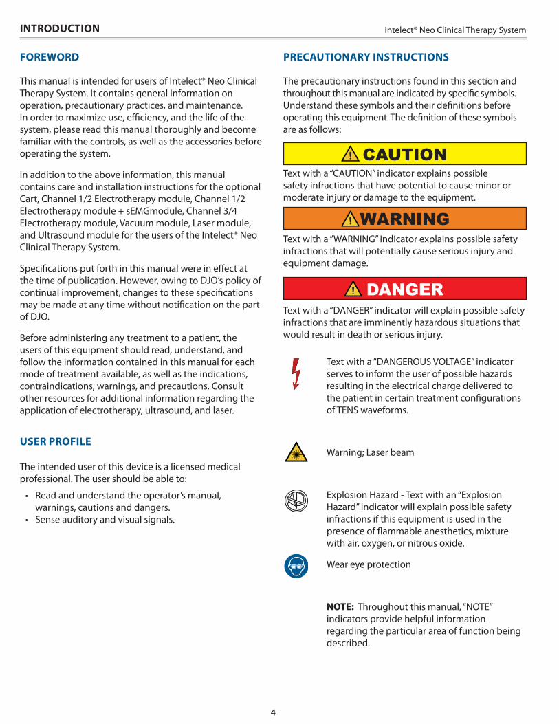
Text with a “DANGEROUS VOLTAGE” indicator serves to inform the user of possible hazards resulting in the electrical charge delivered to the patient in certain treatment configurations of TENS waveforms .
Warning; Laser beam
Explosion Hazard - Text with an “Explosion Hazard” indicator will explain possible safety infractions if this equipment is used in the presence of flammable anesthetics, mixture with air, oxygen, or nitrous oxide .
Wear eye protection
NOTE: Throughout this manual, “NOTE” indicators provide helpful information regarding the particular area of function being described .
CAUTIONText with a “CAUTION” indicator explains possible safety infractions that have potential to cause minor or moderate injury or damage to the equipment .
Text with a “WARNING” indicator explains possible safety infractions that will potentially cause serious injury and equipment damage .
Text with a “DANGER” indicator will explain possible safety infractions that are imminently hazardous situations that would result in death or serious injury .
The precautionary instructions found in this section and throughout this manual are indicated by specific symbols . Understand these symbols and their definitions before operating this equipment . The definition of these symbols are as follows:
PRECAUTIONARY INSTRUCTIONS
WARNING
DANGER
INTRODUCTION
5
Intelect® Neo Clinical Therapy System INTRODUCTION
GENERAL TERMINOLOGY
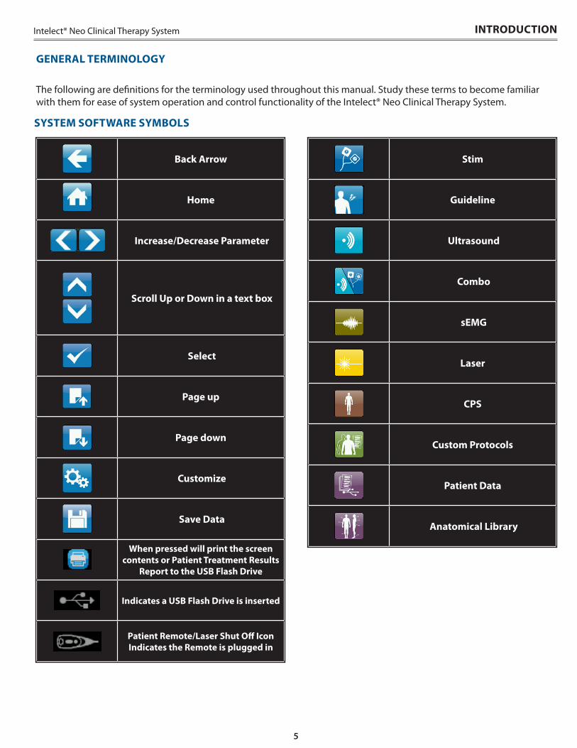
The following are definitions for the terminology used throughout this manual . Study these terms to become familiar with them for ease of system operation and control functionality of the Intelect® Neo Clinical Therapy System .
SYSTEM SOFTWARE SYMBOLS
Stim
Guideline
Ultrasound
Combo
sEMG
Laser
CPS
Custom Protocols
Patient Data
Anatomical Library
Back Arrow
Home
Increase/Decrease Parameter
Scroll Up or Down in a text box
Select
Page up
Page down
Customize
Save Data
When pressed will print the screen contents or Patient Treatment Results
Report to the USB Flash Drive
Indicates a USB Flash Drive is inserted
Patient Remote/Laser Shut Off Icon Indicates the Remote is plugged in
6
Intelect® Neo Clinical Therapy SystemINTRODUCTION
DESCRIPTION OF DEVICE MARKINGS
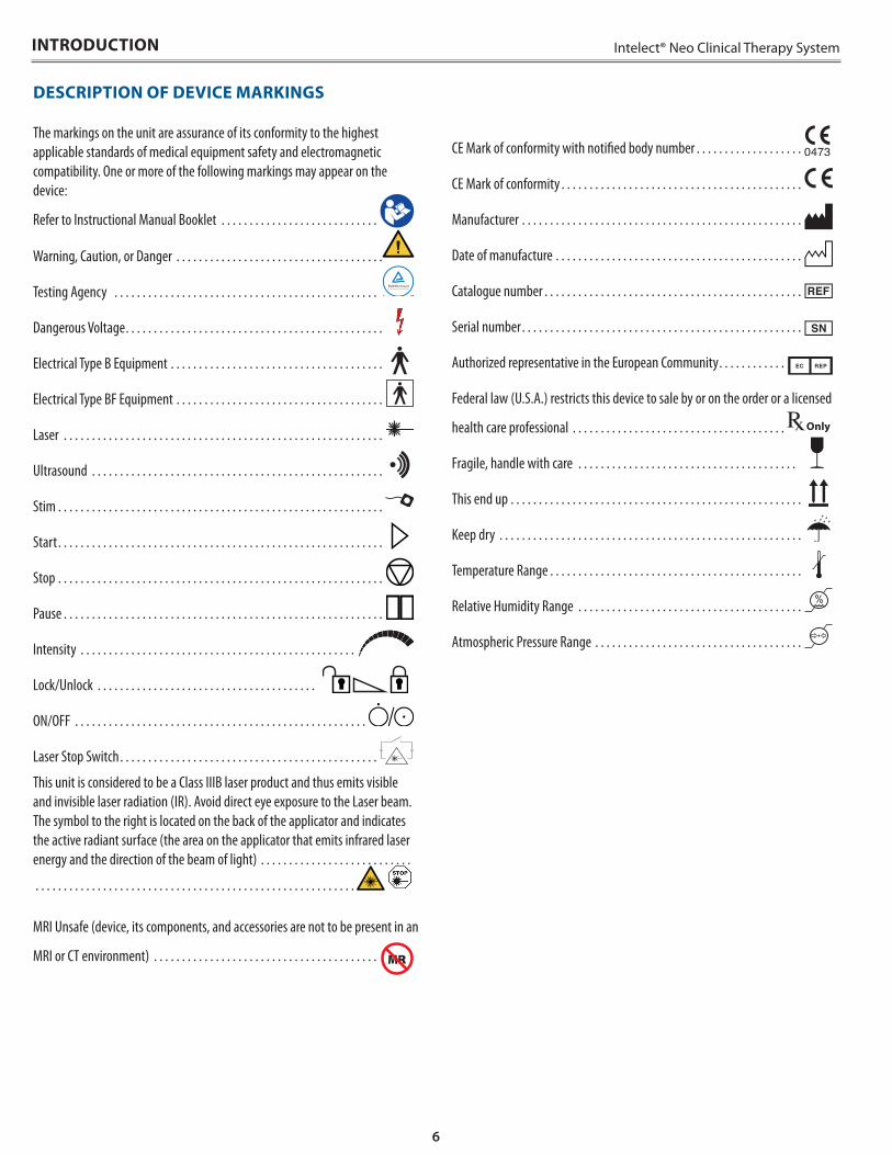
The markings on the unit are assurance of its conformity to the highest applicable standards of medical equipment safety and electromagnetic compatibility. One or more of the following markings may appear on the device:
Refer to Instructional Manual Booklet . . . . . . . . . . . . . . . . . . . . . . . . . . . .
Warning, Caution, or Danger . . . . . . . . . . . . . . . . . . . . . . . . . . . . . . . . . . . . .
Testing Agency . . . . . . . . . . . . . . . . . . . . . . . . . . . . . . . . . . . . . . . . . . . . . . .
Dangerous Voltage. . . . . . . . . . . . . . . . . . . . . . . . . . . . . . . . . . . . . . . . . . . . . .
Electrical Type B Equipment . . . . . . . . . . . . . . . . . . . . . . . . . . . . . . . . . . . . . .
Electrical Type BF Equipment . . . . . . . . . . . . . . . . . . . . . . . . . . . . . . . . . . . . .
Laser . . . . . . . . . . . . . . . . . . . . . . . . . . . . . . . . . . . . . . . . . . . . . . . . . . . . . . . . .
Ultrasound . . . . . . . . . . . . . . . . . . . . . . . . . . . . . . . . . . . . . . . . . . . . . . . . . . . .
Stim . . . . . . . . . . . . . . . . . . . . . . . . . . . . . . . . . . . . . . . . . . . . . . . . . . . . . . . . . .
Start. . . . . . . . . . . . . . . . . . . . . . . . . . . . . . . . . . . . . . . . . . . . . . . . . . . . . . . . . .
Stop . . . . . . . . . . . . . . . . . . . . . . . . . . . . . . . . . . . . . . . . . . . . . . . . . . . . . . . . . .
Pause . . . . . . . . . . . . . . . . . . . . . . . . . . . . . . . . . . . . . . . . . . . . . . . . . . . . . . . . .
Intensity . . . . . . . . . . . . . . . . . . . . . . . . . . . . . . . . . . . . . . . . . . . . . . . . .
Lock/Unlock . . . . . . . . . . . . . . . . . . . . . . . . . . . . . . . . . . . . . . .
ON/OFF . . . . . . . . . . . . . . . . . . . . . . . . . . . . . . . . . . . . . . . . . . . . . . . . . . . .
Laser Stop Switch. . . . . . . . . . . . . . . . . . . . . . . . . . . . . . . . . . . . . . . . . . . . . .
This unit is considered to be a Class IIIB laser product and thus emits visible and invisible laser radiation (IR). Avoid direct eye exposure to the Laser beam. The symbol to the right is located on the back of the applicator and indicates the active radiant surface (the area on the applicator that emits infrared laser energy and the direction of the beam of light) . . . . . . . . . . . . . . . . . . . . . . . . . . .
. . . . . . . . . . . . . . . . . . . . . . . . . . . . . . . . . . . . . . . . . . . . . . . . . . . . . . . . .
MRI Unsafe (device, its components, and accessories are not to be present in an
MRI or CT environment) . . . . . . . . . . . . . . . . . . . . . . . . . . . . . . . . . . . . . . . .
CE Mark of conformity with notified body number . . . . . . . . . . . . . . . . . . .
CE Mark of conformity . . . . . . . . . . . . . . . . . . . . . . . . . . . . . . . . . . . . . . . . . . .
Manufacturer . . . . . . . . . . . . . . . . . . . . . . . . . . . . . . . . . . . . . . . . . . . . . . . . . .
Date of manufacture . . . . . . . . . . . . . . . . . . . . . . . . . . . . . . . . . . . . . . . . . . . .
Catalogue number . . . . . . . . . . . . . . . . . . . . . . . . . . . . . . . . . . . . . . . . . . . . . .
Serial number. . . . . . . . . . . . . . . . . . . . . . . . . . . . . . . . . . . . . . . . . . . . . . . . . .
Authorized representative in the European Community. . . . . . . . . . . .
Federal law (U.S.A.) restricts this device to sale by or on the order or a licensed
health care professional . . . . . . . . . . . . . . . . . . . . . . . . . . . . . . . . . . . . . .
Fragile, handle with care . . . . . . . . . . . . . . . . . . . . . . . . . . . . . . . . . . . . . . .
This end up . . . . . . . . . . . . . . . . . . . . . . . . . . . . . . . . . . . . . . . . . . . . . . . . . . . .
Keep dry . . . . . . . . . . . . . . . . . . . . . . . . . . . . . . . . . . . . . . . . . . . . . . . . . . . . . .
Temperature Range . . . . . . . . . . . . . . . . . . . . . . . . . . . . . . . . . . . . . . . . . . . . .
Relative Humidity Range . . . . . . . . . . . . . . . . . . . . . . . . . . . . . . . . . . . . . . . .
Atmospheric Pressure Range . . . . . . . . . . . . . . . . . . . . . . . . . . . . . . . . . . . . .
7
Intelect® Neo Clinical Therapy System
Indications
The Intelect® Neo Clinical Therapy System offers VMS, VMS Burst, VMS-FR, Russian, TENS, TENS HAN, High Voltage Pulsed Current (HVPC), Interferential, and Premodulated Waveforms, providing the following benefits:
• Relaxation of muscle spasms• Prevention or retardation of disuse atrophy• Increasing local blood circulation• Muscle re-education• Maintaining or increasing range of motion• Immediate postsurgical stimulation of calf muscles to
prevent venous thrombosis
Additional Indications for Microcurrent, Interferential, Premodulated, VMS™, VMS™ Burst, VMS™ FR, TENS, TENS HAN Waveforms:
• Temporary symptomatic relief or management of chronic, intractable pain
• Temporary relief of post -traumatic acute pain• Temporary relief of post -surgical acute pain
Indications for DC (Direct Current) Mode:
• Relaxation of muscle spasm
Indications for Iontophoresis:
• Iontophoresis can be used for the administration of soluble salts or other drugs into the body for medical purposes as an alternative to hypodermic injection .
Indications for FES:
• Stimulation of the muscles of the leg and ankle of partially paralyzed patients to provide flexion of the foot and thus improve the patient’s gait .
Contraindications
The Intelect® Neo Clinical Therapy System should NOT be used under the following conditions:
• Do not use for symptomatic local pain relief unless etiology is established or unless a pain syndrome has been diagnosed .
• Do not use when cancerous lesions are present in the treatment area .
• Do not apply stimulation over swollen, infected, inflamed areas or skin eruptions (e .g ., phlebitis, thrombophlebitis, varicose veins, etc .) .
• Do not use when patient is suspected or known to have infectious disease and/or disease where it is advisable, for general medical purposes, to suppress heat or fevers .
• Do not place electrode placements to the carotid sinus region (anterior neck) or transcerebrally (through the head) .
• Do not use on pregnant women . Safety has not been established for the use of therapeutic electrical stimulation during pregnancy .
• Do not use powered muscle stimulators or TENS waveforms on patients with cardiac demand pacemakers .
• Do not use Intelect® Neo Clinical Therapy System on patients who have or have had implantable neurostimulating cardiac demand pacemakers, ICD, or other implantable electronic devices .
• Do not use Intelect® Neo Clinical Therapy System on patients with body worn electro mechanical medical devices, i .e . insulin pump .
• Do not use this system in an MRI or CT environment . The Intelect® Neo Clinical Therapy System, its components, and accessories are not to be present in an MRI or CT environment .
ELECTROTHERAPY INDICATIONS
INDICATIONS FOR USE
8
Intelect® Neo Clinical Therapy SystemINDICATIONS FOR USE
Additional Precautions
• Use caution for patients with suspected or diagnosed heart problems .
• Use caution for patients with suspected or diagnosed epilepsy .
• Use caution in the presence of the following: - When there is a tendency to hemorrhage
following acute trauma or fracture - Following recent surgical procedures when
muscle contraction may disrupt the healing process
- Over a menstruating or pregnant uterus - Over areas of the skin that lack normal sensation
• Some patients may experience skin irritation or hypersensitivity due to the electrical stimulation or electrical conductive medium . The irritation can usually be reduced by using an alternative conductive medium or an alternative electrode placement .
• Electrode placement and stimulation settings should be based on the guidance of the prescribing practitioner .
• Powered muscle stimulators should be used only with the lead wires and electrodes recommended for use by the manufacturer .
• With TENS waveforms, isolated cases of skin irritation may occur at the site of electrode placement following long-term application .
• The effective management of pain by TENS waveforms is highly dependent upon patient selection by a person qualified in pain management .
Adverse Effects
• Skin irritation and burns beneath the electrodes have been reported with the use of powered muscle stimulators .
• Potential adverse effects with TENS are skin irritation and electrode burns .
ELECTROTHERAPY INDICATIONS (CONTINUED)
9
Intelect® Neo Clinical Therapy System INDICATIONS FOR USE
SEMG & STIM INDICATIONS
Indications
• Stroke rehab by muscle re-education• Relaxation of muscle spasms• Prevention or retardation of disuse atrophy• Increase local blood circulation• Muscle re-education• Maintaining or increasing range of motion
Indications for EMG alone:
• To determine the activation timing of muscles for: - Retraining of muscle activation - Coordinating of muscle activation
• Any indication of the force produced by muscle for control and maintenance of muscle contractions
- Relaxation muscle training - Muscle re-education
Indications for incontinence:
• Provide biofeedback for the purpose of rehabilitation of pelvic floor muscles for the treatment of urinary Incontinence .
Contraindications
The Intelect® Neo Clinical Therapy System should not be used under the following conditions:
• Do not use for symptomatic local pain relief unless etiology is established or unless a pain syndrome has been diagnosed .
• Do not use when cancerous lesions are present in the treatment area .
• Do not apply stimulation over swollen, infected, inflamed areas or skin eruptions (e .g ., phlebitis, thrombophlebitis, varicose veins, etc .) .
• Other contraindications are patients suspected of carrying serious infectious disease and/or disease where it is advisable, for general medical purposes, to suppress heat or fevers .
• Do not place electrode placements to the carotid sinus region (anterior neck) or transcerebrally (through the head) .
• Safety has not been established for the use of therapeutic electrical stimulation during pregnancy .
• Do not use powered muscle stimulators or TENS waveforms on patients with cardiac demand pacemakers .
• Do not use Intelect® Neo Clinical Therapy System on patients who have or have had implantable neurostimulating cardiac demand pacemakers, ICD, or other implantable electronic devices .
• Do not use Intelect® Neo Clinical Therapy System on patients with body worn electro mechanical medical devices, i .e . insulin pump .
• Do not use this system in an MRI or CT environment . The Intelect® Neo Clinical Therapy System, its components, and accessories are not to be present in an MRI or CT environment .
Additional Precautions
• Use caution for patients with suspected or diagnosed heart problems .
• Use caution for patients with suspected or diagnosed epilepsy .
• Use caution in the presence of the following: - When there is a tendency to hemorrhage
following acute trauma or fracture - Following recent surgical procedures when
muscle contraction may disrupt the healing process
- Over a menstruating or pregnant uterus - Over areas of the skin that lack normal sensation
• Some patients may experience skin irritation or hypersensitivity due to the electrical stimulation or electrical conductive medium . The irritation can usually be reduced by using an alternative conductive medium or an alternative electrode placement .
• Electrode placement and stimulation settings should be based on the guidance of the prescribing practitioner .
• Powered muscle stimulators should be used only with the lead wires and electrodes recommended for use by the manufacturer .
• With TENS waveforms, isolated cases of skin irritation may occur at the site of electrode placement following long term application .
• The effective management of pain by TENS waveforms is highly dependent upon patient selection by a person qualified in the management of pain patients .
Adverse Effects
• Skin irritation and burns beneath the electrodes have been reported with the use of powered muscle stimulators .
• Potential adverse effects with TENS are skin irritation and electrode burns .
10
Intelect® Neo Clinical Therapy SystemINDICATIONS FOR USE
Indications
Application of therapeutic deep heat for the treatment of selected sub-chronic and chronic medical conditions such as:
• Temporary relief of pain, muscle spasms, and joint contractures
• Temporary relief of pain, muscle spasms, and joint contractures that may be associated with:
- Adhesive capsulitis - Bursitis with slight calcification - Myositis - Soft tissue injuries - Shortened tendons due to past injuries and scar
tissues• Temporary relief of sub-chronic and chronic pain and
joint contractures resulting from: - Capsular tightness - Capsular scarring
Contraindications
• This device should not be used for symptomatic local pain relief unless etiology is established or unless a pain syndrome has been diagnosed .
• This device should not be used when cancerous lesions are present in the treatment area .
• Other contraindications are patients suspected of carrying serious infectious disease and disease where it is advisable for general medical purposes to suppress heat or fevers .
• This device should not be used over or near bone growth centers until bone growth is complete .
• This device should not be used over the thoracic area if the patient is using a cardiac pacemaker .
• This device should not be used over a healing fracture .• This device should not be used over or applied to the
eye .• This device should not be used over a pregnant uterus .• Tissue necrosis might result if the device is used on
ischemic tissues in individuals with vascular disease, where the blood supply would not keep up with the metabolic demand .
• Do not use Intelect® Neo Clinical Therapy System on patients who have or have had implantable neurostimulating cardiac demand pacemakers, ICD, or other implantable electronic devices .
• Do not use Intelect® Neo Clinical Therapy System on patients with body worn electro mechanical medical devices, i .e . insulin pump .
• Do not use this system in an MRI or CT environment . The Intelect® Neo Clinical Therapy System, its components, and accessories are not to be present in an MRI or CT environment .
Additional Precautions
Additional precautions should be used when ultrasound is used on patients with the following conditions:
• Over an area of the spinal cord following a laminectomy, i .e ., when major covering tissues have been removed
• Over anesthetic areas• On patients with hemorrhagic diatheses
ULTRASOUND INDICATIONS
11
Intelect® Neo Clinical Therapy System INDICATIONS FOR USE
Indications
To provide topical heating for the following:
• Increasing local blood circulation• Relieving minor muscle and joint aches, pains, and
stiffness• Relaxing muscles• Relieving muscle spasms• Relieving minor pain and stiffness associated with
arthritis• Promoting nerve regeneration, bone growth, and
ligament repair• Healing wounds
Contraindications
The Intelect® Neo Clinical Therapy System Laser should NOT be used:
• Where analgesia may mask progressive pathology, and where the practitioner would normally avoid the use of any other analgesia in order to retain the beneficial aspects of pain
• For direct aim into the eyes of humans or animals over areas injected with steroids in the past 2-3 weeks
• Over areas that are suspicious or contain potentially cancerous tissue
• Over areas of active hemorrhage• Over a pregnant uterus• Over the neck (thyroid or carotid sinus region) or chest
(vagus nerve or cardiac region of the thorax)• Directly over areas with open wounds, unless covered
with a clear protective barrier• Treatment over sympathetic ganglia• For symptomatic local pain relief unless etiology
is established or unless a pain syndrome has been diagnosed
• On patients suspected of carrying serious infectious disease and/or disease where it is advisable, for general medical purposes, to suppress heat or fevers
• Over or near bone growth centers until bone growth is complete
• Over the thoracic area if the patient is using a cardiac pacemaker
• Over or applied to the eye• On ischemic tissues in individuals with vascular
disease where the blood supply would be unable to follow the increase in metabolic demand and tissue necrosis might result
• Do not use Intelect® Neo Clinical Therapy System on patients who have or have had implantable neurostimulating cardiac demand pacemakers, ICD, or other implantable electronic devices .
LASER INDICATIONS
• Do not use Intelect® Neo Clinical Therapy System on patients with body worn electro mechanical medical devices, i .e . insulin pump .
• Do not use this system in an MRI or CT environment . The Intelect® Neo Clinical Therapy System, its components and accessories, are not to be present in an MRI or CT environment .
Additional Precautions
Additional precaution should be used when the Laser is used on patients with the following conditions:
• Over an area of the spinal cord following a laminectomy, i .e ., when major covering tissues have been removed
• Over anesthetic areas• On patients with hemorrhagic diatheses
Preventing Adverse Effects
Perform the following procedures to avoid the negative effects of Laser therapy:
• Inspect the treatment area during and following treatment, and discontinue if an adverse reaction does occur .
• Higher output levels have a greater potential for patient discomfort . Choose a lower dosage to reduce output or select a pulsed duty cycle to decrease patient discomfort .
Factors that Affect Treatment
The following factors may affect Laser treatment:
• Color of skin (light or dark)• Age of lesion• Depth of lesion• Sensitivity of patient• Type of tissue• Medications that increase sensitivity to light
12
Intelect® Neo Clinical Therapy System
PRODUCT DESCRIPTION
The Intelect® Neo Clinical Therapy System is a modular system used with or without an optional Cart, allowing for the inclusion of Channel 1/2 Electrotherapy module with or without sEMG, Channel 3/4 Electrotherapy module, Vacuum module, Laser module, and Ultrasound module .
To maximize functionality and life of Intelect® Neo, be sure to:
• Stay current with the latest clinical developments in the field of electrotherapy, ultrasound, laser therapy, sEMG, and sEMG + electrotherapy .
• Observe all applicable precautionary measures for treatment .
• Keep informed of appropriate indications and contraindications for the use of the Intelect® Neo Clinical Therapy System .
NOTE: This equipment is to be used only under the prescription and supervision of a licensed medical practitioner .
DEVICE DESCRIPTION
13
Intelect® Neo Clinical Therapy System DEVICE DESCRIPTION
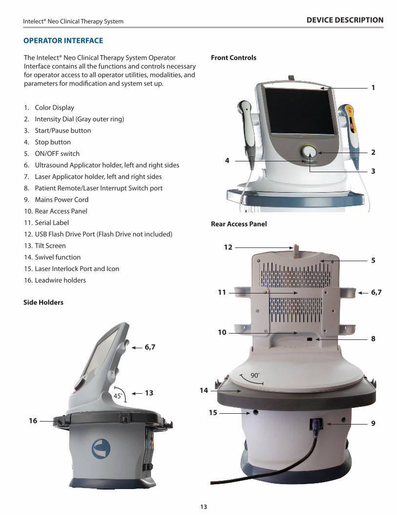
OPERATOR INTERFACE
1 . Color Display
2 . Intensity Dial (Gray outer ring)
3 . Start/Pause button
4 . Stop button
5 . ON/OFF switch
6 . Ultrasound Applicator holder, left and right sides
7 . Laser Applicator holder, left and right sides
8 . Patient Remote/Laser Interrupt Switch port
9 . Mains Power Cord
10 . Rear Access Panel
11 . Serial Label
12 . USB Flash Drive Port (Flash Drive not included)
13 . Tilt Screen
14 . Swivel function
15 . Laser Interlock Port and Icon
16 . Leadwire holders
45º
Front Controls
Side Holders
Rear Access Panel
The Intelect® Neo Clinical Therapy System Operator Interface contains all the functions and controls necessary for operator access to all operator utilities, modalities, and parameters for modification and system set up .
90º
1
2
5
8
9
6,7
6,7
13
4
12
11
10
14
1516
3
14
Intelect® Neo Clinical Therapy SystemGENERAL WARNINGS AND PRECAUTIONS
• Read, understand, and practice the precautionary and operating instructions. Know the limitations and hazards associated with using any electrical stimulation, Laser device or ultrasound device. Observe the precautionary and operational decals placed on the unit.
• All modalities should be routinely checked before each use to determine that all controls function normally, especially that the intensity control does properly adjust the intensity of the ultrasonic power output in a stable manner. Also, determine that the treatment time control does actually terminate ultrasonic power output when the timer reaches zero.
• DO NOT use sharp objects such as a pencil point or ballpoint pen to operate the buttons on the control panel.
• This unit should be operated at 10°C to 45°C and 0% to 90% Relative Humidity. The unit should be transported and stored at 0°C to 60°C and 0% to 95% Relative Humidity.
• Handle Ultrasound Applicator and Laser Applicator with care. Inappropriate handling may adversely affect its characteristics.
• Before each use, inspect Ultrasound Applicator for cracks, which may allow the ingress of conductive fluid.
• Inspect Applicator cables and associated connectors before each use.
• Device is designed to comply with electromagnetic safety standards. This equipment generates, uses, and can radiate radio frequency energy and, if not installed and used in accordance with instructions, may cause harmful interference to other devices in the vicinity. However, there is no guarantee that interference will not occur in a particular installation. Harmful interference to other devices can be determined by turning this equipment on and off. Try to correct the interference using one or more of the following:
- Reorient or relocate the receiving device
- Increase the separation between the equipment
- Connect the equipment to an outlet on a different circuit from that to which the other device(s) are connected and consult the factory field service technician for help.
- Consult your authorized DJO dealer for help.
• Do not operate this unit when connected to any unit other than DJO devices or accessories specifically described in user or service manuals.
• Use of controls, adjustments or performance of procedures other than those specified herein may result in hazardous exposure to Laser energy.
• DO NOT disassemble, modify, or remodel the unit or accessories. This may cause unit damage, malfunction, electrical shock, fire, or personal injury.
• Failure to use and maintain the Intelect® Neo Clinical Therapy System, its modules, and its accessories in accordance with the instructions outlined in this manual will invalidate the warranty.
• DO NOT permit foreign materials, liquids or cleaning agents to enter the unit, including, but not limited to, inflammables, water, and metallic objects from entering the unit, to prevent unit damage, malfunction, electrical shock, fire, or personal injury.
• If you have difficulty operating the unit after carefully reviewing this user manual, contact your DJO dealer for assistance.
• DO NOT remove the front and back covers. Doing so may cause unit damage, malfunction, electrical shock, fire, or personal injury. There are no user-serviceable parts inside the unit. If a malfunction occurs, discontinue use immediately and consult dealer for repair service.
• Use of parts or materials other than DJO’s can degrade minimum safety.
• The Intelect® Neo Clinical Therapy System is not designed to prevent the ingress of water or liquids. Ingress of water or liquids could cause malfunction of internal components of the system and therefore create a risk of injury to the patient.
• The Intelect® Neo Vacuum Electrode Module is designed to operate only when properly installed in the Intelect® Neo Clinical Therapy System Cart.
• Before each use, inspect Vacuum Electrode Cups and Lead Hoses for cracks and damage which may not allow the vacuum to properly secure the electrodes.
• Drain the Vacuum Electrode Module water reservoir regularly to prevent excessive accumulation from electrode sponge water.
• Periodic flushing of the Vacuum system and the Vacuum reservoir are required to maintain factory functionality of the Vacuum Electrode Module. Refer to the MAINTENANCE section on page 77 for proper instructions.
• DO NOT operate the Intelect® Neo Clinical Therapy System within the vicinity or environment as any microware and RF shortwave diathermy system.
• DO NOT operate the Intelect® Neo Clinical Therapy System within the vicinity or environment as an ultrasonic diathermy system. The Ultrasound (diathermy) Module of the Intelect® Neo Clinical Therapy System does not require separation distance.
• Caution should always be exercised with current densities more than 2mA/cm2.
CAUTION CAUTION

15
Intelect® Neo Clinical Therapy System GENERAL WARNINGS AND PRECAUTIONS
• This device should be used only under the continued supervision of a physician or licensed practitioner.
• Be sure to read all instructions for operation before treating patient.
• Make certain the unit is electrically grounded by connecting only to a grounded electrical service receptacle conforming to the applicable national and local electrical codes.
• Care must be taken when operating this equipment around other equipment. Potential electromagnetic or other interference could occur to this or to the other equipment. Try to minimize this interference by not using other equipment in conjunction with it.
• The safety of TENS waveforms for use during pregnancy or birth has not been established.
• TENS is not effective for pain of central origin. (This includes headache.)
• TENS waveforms have no curative value.
• Electronic monitoring equipment (such as ECG monitors and ECG alarms) may not operate properly when electrical stimulation is in use.
• TENS is a symptomatic treatment, and as such, suppresses the sensation of pain which would otherwise serve as a protective mechanism.
• Inspect the plastic lens of the laser head for blemishes, deformation, pitting, scratches, discoloration, and cleanliness before each use.
• Do not drop the applicator or unit on hard surfaces or submerge in water. These actions will damage the applicator and unit. Damage resulting from these conditions is not covered under the warranty.
• Use of controls or adjustments or performance of procedures other than those specified herein may result in hazardous exposure to Laser energy.
• This device should be kept out of the reach of children.
• Use of other accessories other than those specified in this User Manual may increase electrical emissions and decrease electrical immunity of the device.
• Contaminated sponges, electrodes, leadwires, and gel can lead to infection.
• Use of electrode with degraded hydrogel can result in burn to the skin.
• DO NOT operate this unit in an environment where other devices are being used that intentionally radiate electromagnetic energy in an unshielded manner.
• Use of contaminated sponge or electrodes with corrosion with vacuum system can result in possible infection or skin irritation.
• Use of electrode with degraded hydro-gel can result in infection to the skin burn.
• Use of electrode on multiple patients can lead to infection.
WARNING WARNING• Clean applicators after each use, otherwise it can lead to cross
contamination and infection.
• Clean vacuum electrodes, sponges, and hoses before each use. Lack of proper cleaning and maintenance may lead to cross-contamination and infection.
• When the Laser Module is not in use, it should be protected against unqualified use.
• Do not treat through clothing.
• Stop treatment immediately if patient experiences discomfort or pain.
• Do not apply laser on an area of skin that has lotion or ointments applied as burns may occur.
• Do not use laser on or over a tattoo.
• The laser head must be cleaned with a disinfectant cleaner (i.e. Virex® II 256) or germicidal cloth (i.e. PDI Sani-Cloth® Plus/Hb) between each therapy session. Ensure no liquids enter into the laser head while cleaning. Do not use any chlorine-based cleaners on the laser head.
• The color of skin, age of lesion, depth of lesion, sensitivity of the patient, tissue type, and medications that increase sensitivity to light may affect therapy.
• Powered muscle stimulators should be used only with the leads and electrodes recommended for use by the manufacturer.
• In the event of all 300-Level or a 200-Level error message that cannot be resolved, immediately stop all use of the system, and contact the dealer or DJO for service. Errors and Warnings in these categories indicate an internal problem with the system that must be tested by DJO or a Trained Technician before any further operation or use of the system.
- Use of a system that indicates an Error or Warning in these categories may pose a risk of injury to the patient, user, or extensive internal damage to the system.
• Use of controls or adjustments or performance of procedures other than those specified herein may result in hazardous exposure to ultrasonic energy.
• Before administering any treatment to a patient you should become acquainted with the operating procedures for each mode of treatment available, as well as the indications, contraindications, warnings and precautions. Consult other resources for additional information regarding the application of each mode of treatment.
• Disconnect the system from the power source before attempting any maintenance, installation, removal, or replacement procedures to prevent electrical shock and possible damage to system.
• Keep electrodes separated during treatment. Electrodes in contact with each other could result in improper stimulation or skin burns.

16
Intelect® Neo Clinical Therapy System
• The Intelect® Neo Clinical Therapy System may be susceptible to Electro-Static Discharge (ESD) at greater than ±4 kV when first grasping either the Ultrasound or Laser applicator. In the event of such a discharge, the Intelect® Neo Clinical Therapy System may experience communication loss with the installed modules. The Intelect® Neo Clinical Therapy System will terminate all active outputs (stim, ultrasound, laser), automatically place the unit in a safe state, and issue an error message 301 or 307.
- To recover from an error message 301 or 307, turn the unit off and on using the ON/OFF switch located at the top of the display. Once the system restarts, re-initiate all treatments that were interrupted.
• To prevent Electro-Static Discharge (ESD) at greater than ±4 kV:
- Grasp and hold the Ultrasound or Laser applicator prior to starting treatment. If the applicator must be put down prior to completion of treatment, stop the current treatment first and then place the applicator in the holder.
- Maintain humidity in the use environment to at least 50% relative humidity.
- Floors should be wood, concrete, or ceramic tile. If floors are covered with synthetic material, DJO recommends implementing additional controls to maintain relative humidity to at least 50%.
- Communicate these ESD-precautionary procedures to healthcare staff, contractors, visitors, and patients.
• Long term effects of chronic electrical stimulation are unknown.
• Stimulation should not be applied over the anterior neck or mouth. Severe spasm of the laryngeal and pharyngeal muscles may occur and the contractions may be strong enough to close the airway or cause difficulty in breathing.
• Stimulation should not be applied transthoracically in that the introduction of electrical current into the heart may cause cardiac arrhythmia.
• Stimulation should not be applied over swollen, infected, and inflamed areas or skin eruptions, e.g., phlebitis, thrombophlebitis, varicose veins, etc.
• Stimulation should not be applied over, or in proximity to, cancerous lesions.
• Electrotherapy output current density is related to electrode size. Improper application may result in patient injury. If any question arises as to the proper electrode size, consult a licensed practitioner prior to therapy session.
• The Intelect® Neo Clinical Therapy System optional modules and associated accessories are designed for use only with the Intelect® Neo Clinical Therapy System.
• Remove the Ultrasound or Laser Applicator by pulling the cable connector only. DO NOT remove by pulling the cable.
• Vacuum electrodes should not be used on patients with thin, papery skin. Vacuum may lead to contact difficulty and bruising.
• Vacuum electrodes are not suitable for patients who are taking steroids, due to the likelihood of bruising.
• Output current density is related to electrode size. Improper application may result in patient injury. If any question arises as to the proper electrode size, consult a licensed practitioner prior to therapy session.
• Do not apply the Ultrasound Applicator to the patient during the Head Warming period. Applicator must remain in Applicator Hook during the Head Warming period.
• Some patients are more sensitive to laser output (i.e., patients taking medications that increase sensitivity to light) and may experience a reaction similar to a heat rash.
• Before each Laser use, clean the plastic lens with a clean cloth. Make certain to apply with a clean cloth. Failure to clean the lens between patient therapy sessions could cause beam fragmentation, which may reduce the effectiveness of the treatment.
• Medical electrical equipment needs special precautions regarding EMC. Portable and mobile RF communication equipment can be affected by other medical electrical devices. If you believe interference is occurring, please consult the ELECTROMAGNETIC COMPATIBILITY (EMC) section on page 83, to assist in removing the interference.
• Common RF emitting devices (e.g., RFID) and electromagnetic security systems (e.g., metal detectors) may interfere with the operation of the Intelect® Neo Clinical Therapy System. The Intelect® Neo Clinical Therapy System has been tested in the presence of these types of devices and while no adverse event occurred, the device should not be operated within the vicinity or environment as another RF emitting device.
WARNINGWARNING
GENERAL WARNINGS AND PRECAUTIONS
17
Intelect® Neo Clinical Therapy System GENERAL WARNINGS AND PRECAUTIONS
• Stimulus delivered by the TENS waveforms of this device, in certain configurations, will deliver a charge of 25 microcoulombs (µC) or greater per pulse and may be sufficient to cause electrocution. Electrical current of this magnitude must not flow through the thorax because it may cause a cardiac arrhythmia.
• Patients with an implanted neurostimulation device must not be treated with or be in close proximity to any shortwave diathermy, therapeutic ultrasound diathermy or laser diathermy anywhere on their body. Energy from diathermy (shortwave, microwave, ultrasound and laser) can be transferred through the implanted neurostimulation system, can cause tissue damage, and can result in severe injury or death. Injury, damage, or death can occur during diathermy therapy even if the implanted neurostimulation system is turned off.
• Handle, clean, and dispose of components and accessories that have come in contact with bodily fluids according to National, Local, and Facility rules, regulations, and procedures.
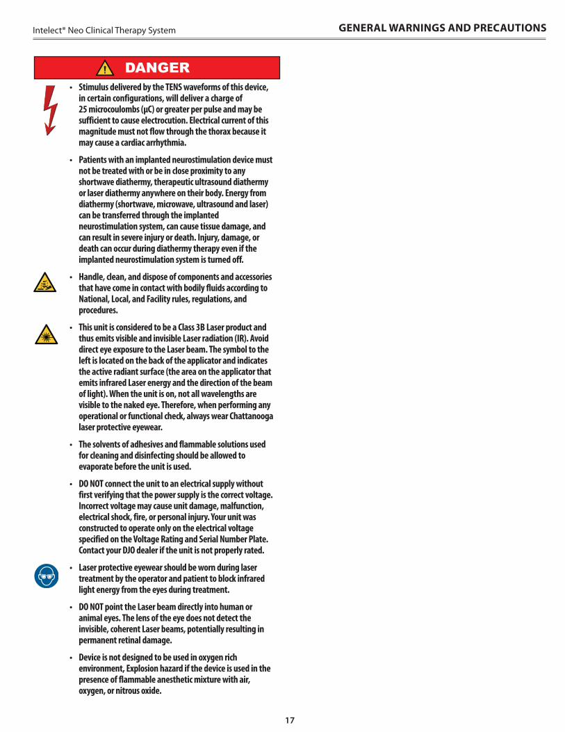
• This unit is considered to be a Class 3B Laser product and thus emits visible and invisible Laser radiation (IR). Avoid direct eye exposure to the Laser beam. The symbol to the left is located on the back of the applicator and indicates the active radiant surface (the area on the applicator that emits infrared Laser energy and the direction of the beam of light). When the unit is on, not all wavelengths are visible to the naked eye. Therefore, when performing any operational or functional check, always wear Chattanooga laser protective eyewear.
• The solvents of adhesives and flammable solutions used for cleaning and disinfecting should be allowed to evaporate before the unit is used.
• DO NOT connect the unit to an electrical supply without first verifying that the power supply is the correct voltage. Incorrect voltage may cause unit damage, malfunction, electrical shock, fire, or personal injury. Your unit was constructed to operate only on the electrical voltage specified on the Voltage Rating and Serial Number Plate. Contact your DJO dealer if the unit is not properly rated.
• Laser protective eyewear should be worn during laser treatment by the operator and patient to block infrared light energy from the eyes during treatment.
• DO NOT point the Laser beam directly into human or animal eyes. The lens of the eye does not detect the invisible, coherent Laser beams, potentially resulting in permanent retinal damage.
• Device is not designed to be used in oxygen rich environment, Explosion hazard if the device is used in the presence of flammable anesthetic mixture with air, oxygen, or nitrous oxide.
DANGER
18
Intelect® Neo Clinical Therapy SystemDETAIL DEVICE DESCRIPTION
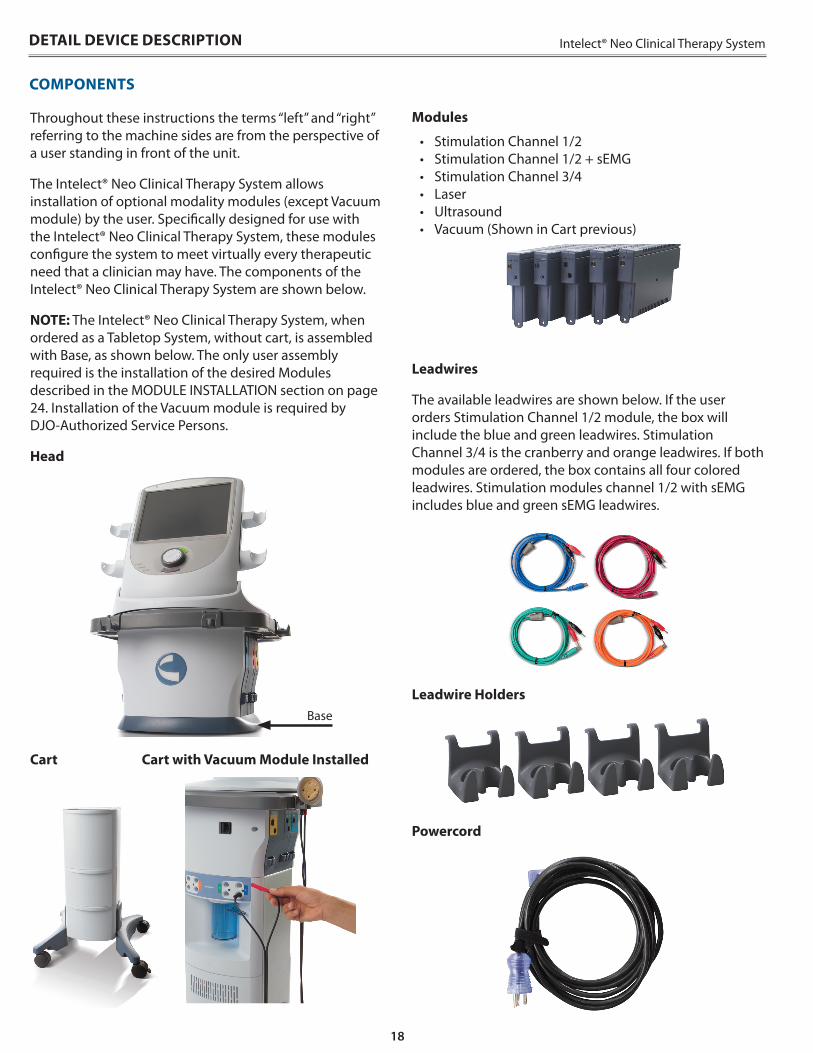
Throughout these instructions the terms “left” and “right” referring to the machine sides are from the perspective of a user standing in front of the unit .
The Intelect® Neo Clinical Therapy System allows installation of optional modality modules (except Vacuum module) by the user . Specifically designed for use with the Intelect® Neo Clinical Therapy System, these modules configure the system to meet virtually every therapeutic need that a clinician may have . The components of the Intelect® Neo Clinical Therapy System are shown below .
NOTE: The Intelect® Neo Clinical Therapy System, when ordered as a Tabletop System, without cart, is assembled with Base, as shown below . The only user assembly required is the installation of the desired Modules described in the MODULE INSTALLATION section on page 24 . Installation of the Vacuum module is required by DJO-Authorized Service Persons .
Head
Cart Cart with Vacuum Module Installed
COMPONENTS
Base
Modules
• Stimulation Channel 1/2• Stimulation Channel 1/2 + sEMG• Stimulation Channel 3/4• Laser• Ultrasound• Vacuum (Shown in Cart previous)
Leadwires
The available leadwires are shown below . If the user orders Stimulation Channel 1/2 module, the box will include the blue and green leadwires . Stimulation Channel 3/4 is the cranberry and orange leadwires . If both modules are ordered, the box contains all four colored leadwires . Stimulation modules channel 1/2 with sEMG includes blue and green sEMG leadwires .
Leadwire Holders
Powercord
19
Intelect® Neo Clinical Therapy System
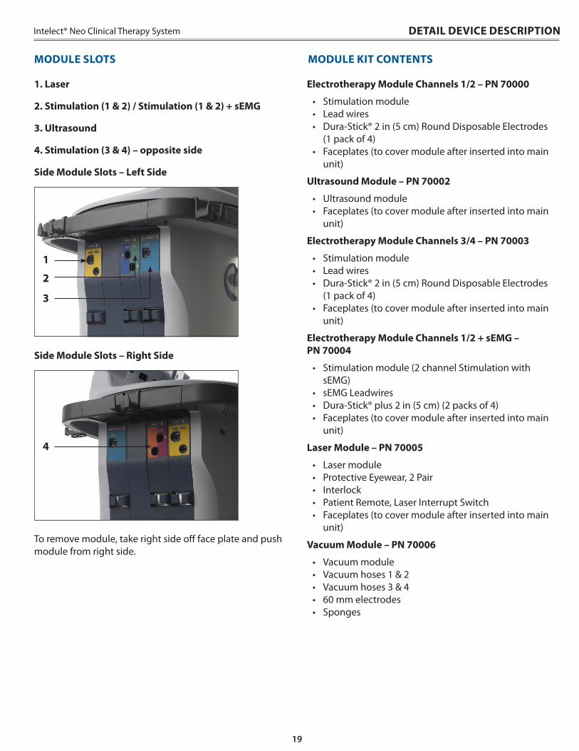
1 . Laser
2 . Stimulation (1 & 2) / Stimulation (1 & 2) + sEMG
3 . Ultrasound
4 . Stimulation (3 & 4) – opposite side
Side Module Slots – Left Side
1
2
3
Side Module Slots – Right Side
4
To remove module, take right side off face plate and push module from right side .
MODULE SLOTS
DETAIL DEVICE DESCRIPTION
Electrotherapy Module Channels 1/2 – PN 70000
• Stimulation module• Lead wires• Dura-Stick® 2 in (5 cm) Round Disposable Electrodes
(1 pack of 4)• Faceplates (to cover module after inserted into main
unit)
Ultrasound Module – PN 70002
• Ultrasound module• Faceplates (to cover module after inserted into main
unit)
Electrotherapy Module Channels 3/4 – PN 70003
• Stimulation module• Lead wires• Dura-Stick® 2 in (5 cm) Round Disposable Electrodes
(1 pack of 4)• Faceplates (to cover module after inserted into main
unit)
Electrotherapy Module Channels 1/2 + sEMG – PN 70004
• Stimulation module (2 channel Stimulation with sEMG)
• sEMG Leadwires• Dura-Stick® plus 2 in (5 cm) (2 packs of 4)• Faceplates (to cover module after inserted into main
unit)
Laser Module – PN 70005
• Laser module• Protective Eyewear, 2 Pair• Interlock • Patient Remote, Laser Interrupt Switch• Faceplates (to cover module after inserted into main
unit)
Vacuum Module – PN 70006
• Vacuum module• Vacuum hoses 1 & 2• Vacuum hoses 3 & 4• 60 mm electrodes • Sponges
MODULE KIT CONTENTS
20
Intelect® Neo Clinical Therapy System
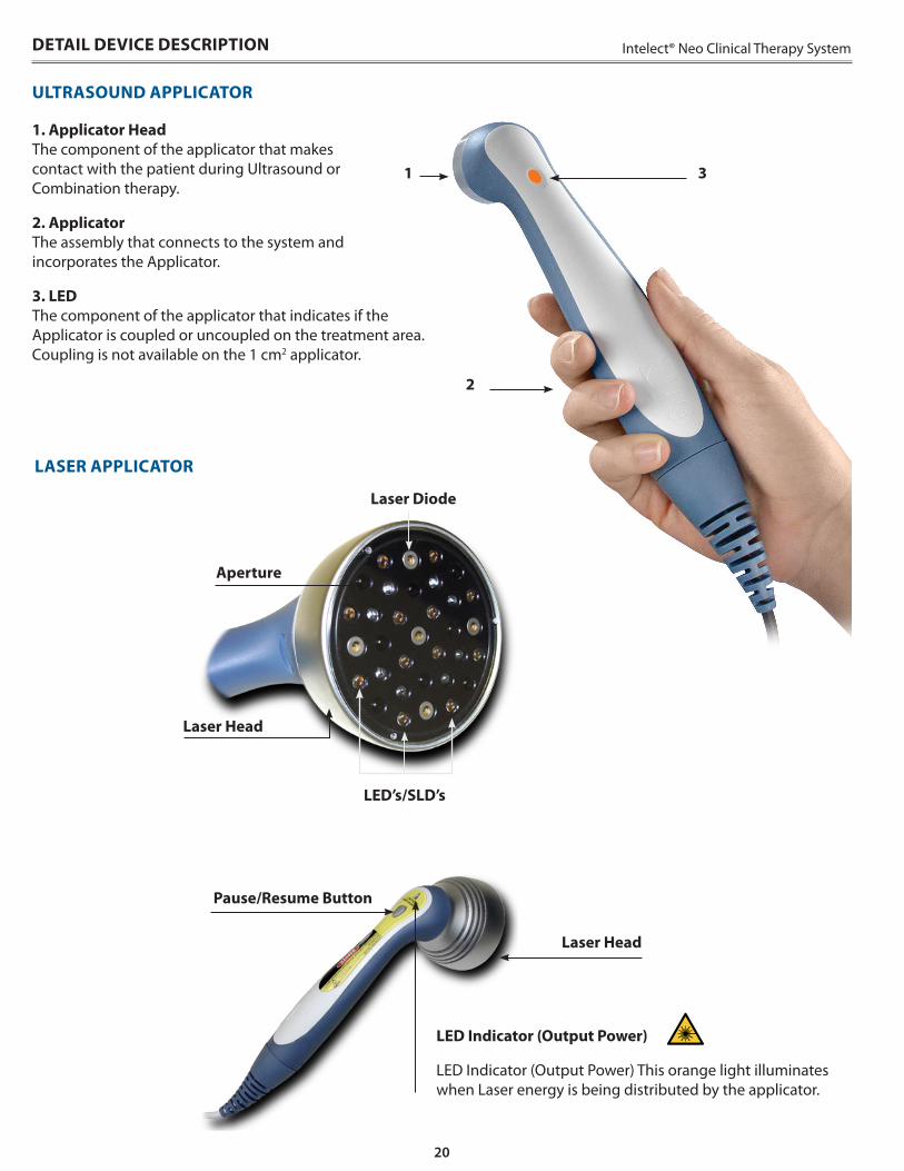
1 . Applicator Head The component of the applicator that makes contact with the patient during Ultrasound or Combination therapy .
2 . Applicator The assembly that connects to the system and incorporates the Applicator .
3 . LED The component of the applicator that indicates if the Applicator is coupled or uncoupled on the treatment area . Coupling is not available on the 1 cm2 applicator .
LED Indicator (Output Power)
LED Indicator (Output Power) This orange light illuminates when Laser energy is being distributed by the applicator .
Pause/Resume Button
Laser Head
LASER APPLICATOR
LED’s/SLD’s
Laser Diode
Aperture
Laser Head
DETAIL DEVICE DESCRIPTION
ULTRASOUND APPLICATOR
3
2
1
21
Intelect® Neo Clinical Therapy System DETAIL DEVICE DESCRIPTION
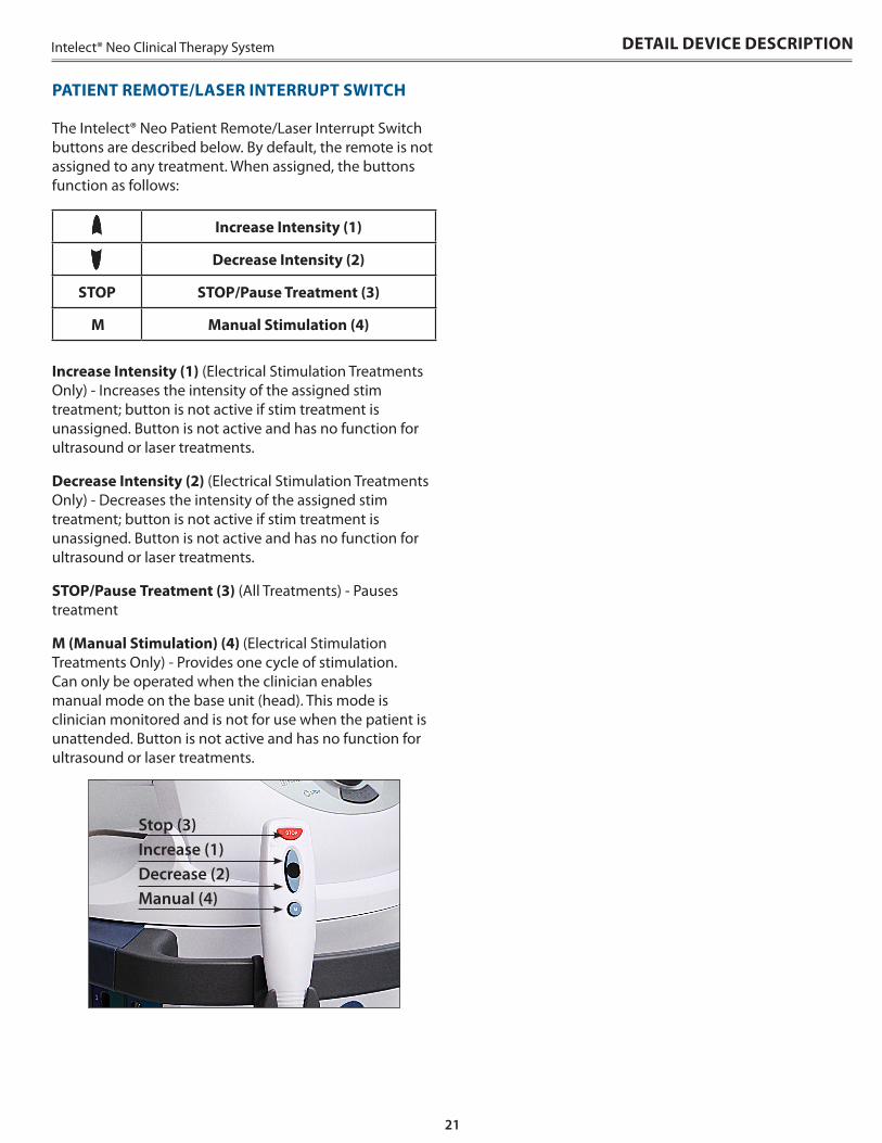
The Intelect® Neo Patient Remote/Laser Interrupt Switch buttons are described below . By default, the remote is not assigned to any treatment . When assigned, the buttons function as follows:
Increase Intensity (1) (Electrical Stimulation Treatments Only) - Increases the intensity of the assigned stim treatment; button is not active if stim treatment is unassigned . Button is not active and has no function for ultrasound or laser treatments .
Decrease Intensity (2) (Electrical Stimulation Treatments Only) - Decreases the intensity of the assigned stim treatment; button is not active if stim treatment is unassigned . Button is not active and has no function for ultrasound or laser treatments .
STOP/Pause Treatment (3) (All Treatments) - Pauses treatment
M (Manual Stimulation) (4) (Electrical Stimulation Treatments Only) - Provides one cycle of stimulation . Can only be operated when the clinician enables manual mode on the base unit (head) . This mode is clinician monitored and is not for use when the patient is unattended . Button is not active and has no function for ultrasound or laser treatments .
PATIENT REMOTE/LASER INTERRUPT SWITCH
Increase Intensity (1)
Decrease Intensity (2)
STOP STOP/Pause Treatment (3)
M Manual Stimulation (4)
Stop (3)Increase (1)Decrease (2)Manual (4)
22
Intelect® Neo Clinical Therapy SystemSETUP INSTRUCTIONS
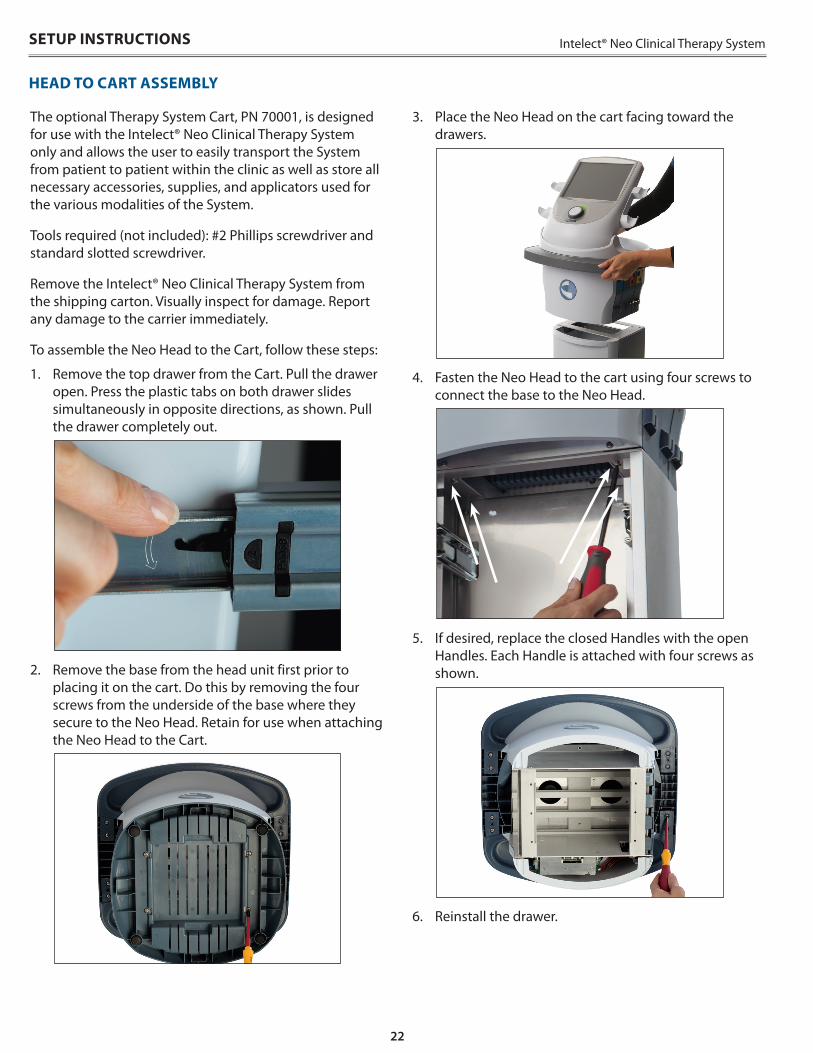
3 . Place the Neo Head on the cart facing toward the drawers .
4 . Fasten the Neo Head to the cart using four screws to connect the base to the Neo Head .
5 . If desired, replace the closed Handles with the open Handles . Each Handle is attached with four screws as shown .
6 . Reinstall the drawer .
The optional Therapy System Cart, PN 70001, is designed for use with the Intelect® Neo Clinical Therapy System only and allows the user to easily transport the System from patient to patient within the clinic as well as store all necessary accessories, supplies, and applicators used for the various modalities of the System .
Tools required (not included): #2 Phillips screwdriver and standard slotted screwdriver .
Remove the Intelect® Neo Clinical Therapy System from the shipping carton . Visually inspect for damage . Report any damage to the carrier immediately .
To assemble the Neo Head to the Cart, follow these steps:
1 . Remove the top drawer from the Cart . Pull the drawer open . Press the plastic tabs on both drawer slides simultaneously in opposite directions, as shown . Pull the drawer completely out .
2 . Remove the base from the head unit first prior to placing it on the cart . Do this by removing the four screws from the underside of the base where they secure to the Neo Head . Retain for use when attaching the Neo Head to the Cart .
HEAD TO CART ASSEMBLY
23
Intelect® Neo Clinical Therapy System SETUP INSTRUCTIONS
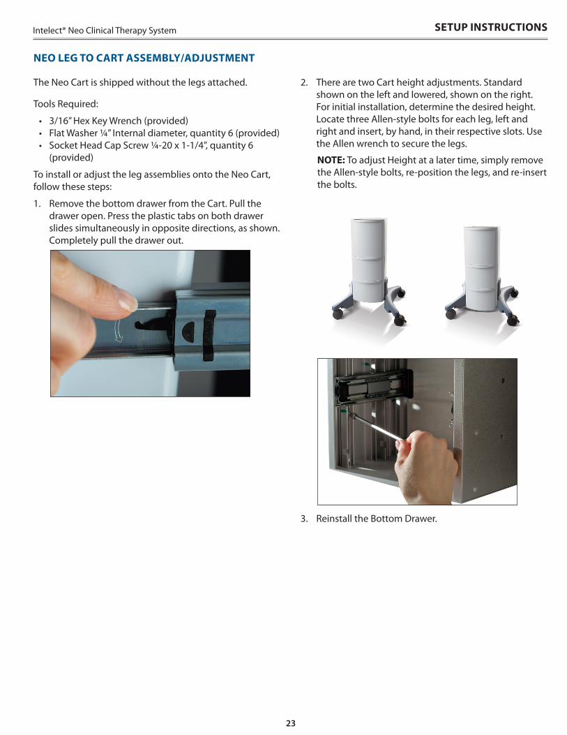
The Neo Cart is shipped without the legs attached .
Tools Required:
• 3/16” Hex Key Wrench (provided)• Flat Washer ¼” Internal diameter, quantity 6 (provided)• Socket Head Cap Screw ¼-20 x 1-1/4”, quantity 6
(provided)
To install or adjust the leg assemblies onto the Neo Cart, follow these steps:
1 . Remove the bottom drawer from the Cart . Pull the drawer open . Press the plastic tabs on both drawer slides simultaneously in opposite directions, as shown . Completely pull the drawer out .
2 . There are two Cart height adjustments . Standard shown on the left and lowered, shown on the right . For initial installation, determine the desired height . Locate three Allen-style bolts for each leg, left and right and insert, by hand, in their respective slots . Use the Allen wrench to secure the legs .
NOTE: To adjust Height at a later time, simply remove the Allen-style bolts, re-position the legs, and re-insert the bolts .
3 . Reinstall the Bottom Drawer .
NEO LEG TO CART ASSEMBLY/ADJUSTMENT
24
Intelect® Neo Clinical Therapy SystemSETUP INSTRUCTIONS
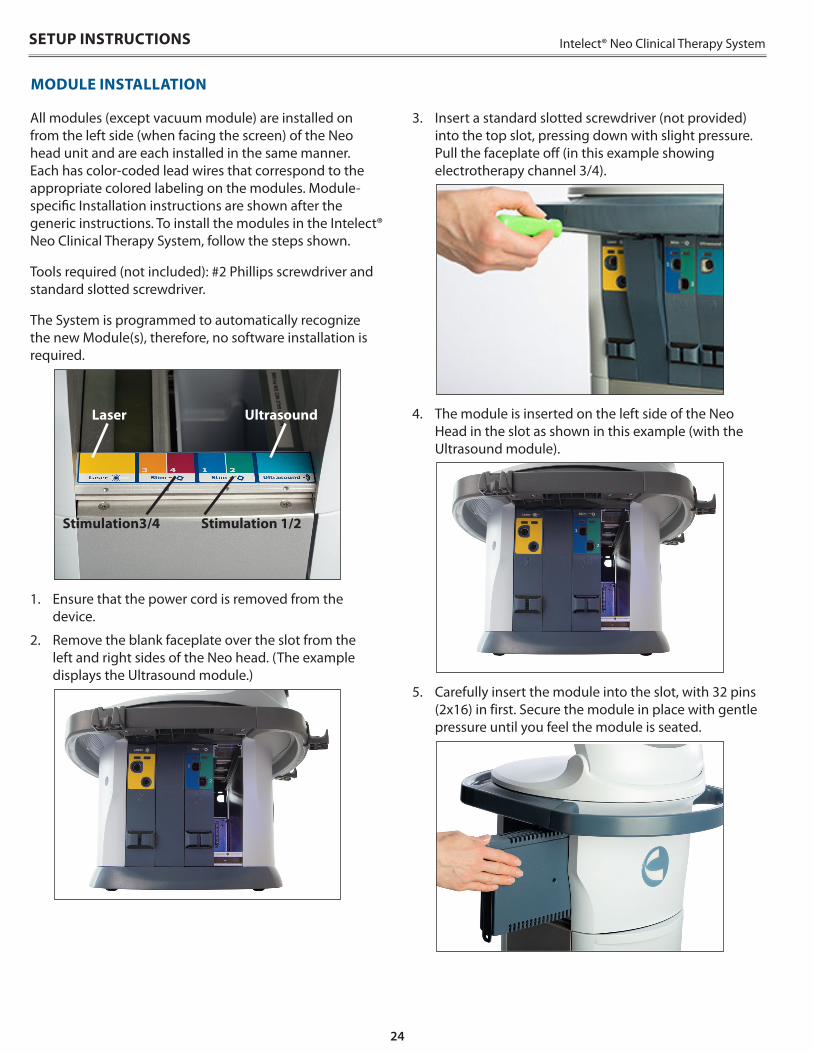
All modules (except vacuum module) are installed on from the left side (when facing the screen) of the Neo head unit and are each installed in the same manner . Each has color-coded lead wires that correspond to the appropriate colored labeling on the modules . Module-specific Installation instructions are shown after the generic instructions . To install the modules in the Intelect® Neo Clinical Therapy System, follow the steps shown .
Tools required (not included): #2 Phillips screwdriver and standard slotted screwdriver .
The System is programmed to automatically recognize the new Module(s), therefore, no software installation is required .
UltrasoundLaser
Stimulation3/4 Stimulation 1/2
1 . Ensure that the power cord is removed from the device .
2 . Remove the blank faceplate over the slot from the left and right sides of the Neo head . (The example displays the Ultrasound module .)
3 . Insert a standard slotted screwdriver (not provided) into the top slot, pressing down with slight pressure . Pull the faceplate off (in this example showing electrotherapy channel 3/4) .
4 . The module is inserted on the left side of the Neo Head in the slot as shown in this example (with the Ultrasound module) .
5 . Carefully insert the module into the slot, with 32 pins (2x16) in first . Secure the module in place with gentle pressure until you feel the module is seated .
MODULE INSTALLATION
25
Intelect® Neo Clinical Therapy System SETUP INSTRUCTIONS
MODULE-SPECIFIC INFORMATIONMODULE INSTALLATION (CONTINUED)
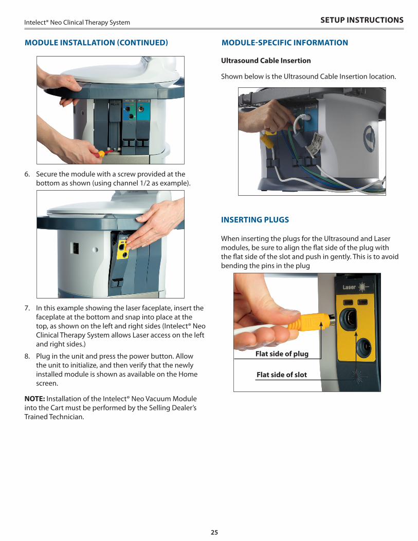
Ultrasound Cable Insertion
Shown below is the Ultrasound Cable Insertion location .
INSERTING PLUGS
When inserting the plugs for the Ultrasound and Laser modules, be sure to align the flat side of the plug with the flat side of the slot and push in gently . This is to avoid bending the pins in the plug
6 . Secure the module with a screw provided at the bottom as shown (using channel 1/2 as example) .
7 . In this example showing the laser faceplate, insert the faceplate at the bottom and snap into place at the top, as shown on the left and right sides (Intelect® Neo Clinical Therapy System allows Laser access on the left and right sides .)
8 . Plug in the unit and press the power button . Allow the unit to initialize, and then verify that the newly installed module is shown as available on the Home screen .
NOTE: Installation of the Intelect® Neo Vacuum Module into the Cart must be performed by the Selling Dealer’s Trained Technician .
Flat side of slot
Flat side of plug

26
Intelect® Neo Clinical Therapy SystemSETUP INSTRUCTIONS
2 . Press the Remote ON/OFF toggle icon to assign or unassign the remote to the selected treatment . The remote can be assigned to only one treatment at a time, however the remote can be reassigned as needed .
When not in use, the Patient Remote/Laser Interrupt Switch can be stored by hooking it onto the leadwire holder clips in the same manner as leadwires and cables, as demonstrated . Shown below .
Complete the following steps to assign the remote to a treatment:
1 . When the remote is plugged into the unit, a Remote ON/OFF toggle icon is displayed on the Treatment review screen in the upper right corner . Shown below:
PATIENT REMOTE/LASER INTERRUPT SWITCH INSTALLATIONTo operate the Patient Remote/Laser Interrupt Switch, plug the remote into the device on the Rear Access Panel receptacle, as shown below:
• Patient Remote/Laser Interrupt Switch is to be used under supervision of a physician or licensed practitioner only.
CAUTION
27
Intelect® Neo Clinical Therapy System SETUP INSTRUCTIONS
• Disconnect the system from the power source before attempting any maintenance, installation, removal or replacement procedures to prevent electrical shock and possible damage to system.
• The laser interlock must be installed by a professional or qualified electrician. Serious eye injury can result if the device is not properly installed. Also, when installing the device for multiple doors, the resistance total may not exceed 4800 ohm.
WARNING
INSTALLING THE LASER INTERLOCK (DOOR INTERRUPT SWITCH)
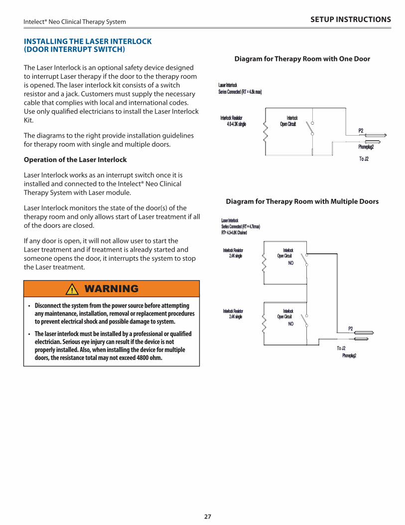
The Laser Interlock is an optional safety device designed to interrupt Laser therapy if the door to the therapy room is opened . The laser interlock kit consists of a switch resistor and a jack . Customers must supply the necessary cable that complies with local and international codes . Use only qualified electricians to install the Laser Interlock Kit .
The diagrams to the right provide installation guidelines for therapy room with single and multiple doors .
Operation of the Laser Interlock
Laser Interlock works as an interrupt switch once it is installed and connected to the Intelect® Neo Clinical Therapy System with Laser module .
Laser Interlock monitors the state of the door(s) of the therapy room and only allows start of Laser treatment if all of the doors are closed .
If any door is open, it will not allow user to start the Laser treatment and if treatment is already started and someone opens the door, it interrupts the system to stop the Laser treatment .
Diagram for Therapy Room with One Door
Diagram for Therapy Room with Multiple Doors
28
Intelect® Neo Clinical Therapy SystemSETUP INSTRUCTIONS
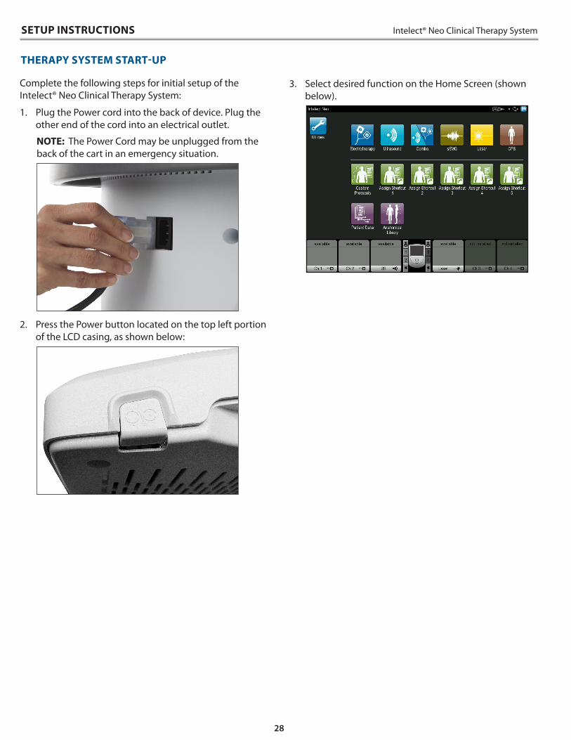
Complete the following steps for initial setup of the Intelect® Neo Clinical Therapy System:
1 . Plug the Power cord into the back of device . Plug the other end of the cord into an electrical outlet .
NOTE: The Power Cord may be unplugged from the back of the cart in an emergency situation .
2 . Press the Power button located on the top left portion of the LCD casing, as shown below:
THERAPY SYSTEM START-UP
3 . Select desired function on the Home Screen (shown below) .
29
Intelect® Neo Clinical Therapy System SYSTEM SPECIFICATIONS
POWER (COMBINATION AND ELECTROTHERAPY UNITS)
Input . . . . . . . . . . . . . . . . . . . . . . . . . . . . 100 - 240 V AC, 2.5A to 1.25A, 50/60 Hz Electrical Class . . . . . . . . . . . . . . . . . . . . . . . . . . . . . . . . . . . . . . . . . . . . . . . CLASS I Mode of Operation. . . . . . . . . . . . . . . . . . . . . . . . . . . . . . . . . . . . . . . . . Continuous
Electrical Type (Degree of Protection)
Ultrasound . . . . . . . . . . . . . . . . . . . . . . . . . . . . . . . . . . . . . . . . . . . . . . .TYPE B
Laser . . . . . . . . . . . . . . . . . . . . . . . . . . . . . . . . . . . . . . . . . . . . . . . . . . . .TYPE B
Electrotherapy . . . . . . . . . . . . . . . . . . . . . . . . . . . . . . . . . . . . . . . . . . .TYPE BF
Electrotherapy & sEMG . . . . . . . . . . . . . . . . . . . . . . . . . . . . . . . . . . . .TYPE BF
Electrotherapy & Vacuum . . . . . . . . . . . . . . . . . . . . . . . . . . . . . . . . . .TYPE BF
Ultrasound & Electrotherapy . . . . . . . . . . . . . . . . . . . . . . . . . . . . . . . .TYPE B
NOTE: All waveforms except High Voltage Pulsed Current (HVPC) have been designed with a 200 mA current limit. VMS™, VMS™ Burst ,and all TENS waveform output intensities are measured, specified, and listed to peak, not peak to peak.
SYSTEM SPECIFICATIONS AND DIMENSIONS
Width Depth Height Weight
Vacuum 10.39” (26.3906 cm) 5.11” (12.9794 cm) 11.07” (28.1178 cm) 4.9lb (2.2226 kg)Module 11.12” (28.2448 cm) 6.34” (16.1036 cm) 1.43” (3.6322 cm) 1lb (0.453592 kg)Head @ 45 degree with Base (Tabletop) 15.89” (40.3606 cm) 15.89” (40.3606 cm) 22.05” (56.007 cm) 20.7lb (9.389362 kg)Cart Lowered (with casters) 23.94” (60.8076 cm) 26.19” (66.5226 cm) 27.41” (69.6214 cm)
29.4lb (13.33562 kg)Cart Raised (with casters) 23.94” (60.8076 cm) 26.19” (66.5226 cm) 30.15” (76.581 cm)Head and raised cart with screen @ 90deg 23.94” (60.8076 cm) 26.19” (66.5226 cm) 52.85” (134.239 cm) 48.9lb (22.18067 kg)
VACUUM SPECIFICATIONS
Vacuum Range . . . . . . . . . . . . . . . . . . . . . . . . . . . . . . . . .0 to 600 mbar maximum . . . . . . . . . . . . . . . . . . . . . . . . . . . . . (0-17.7 inches mercury maximum) +/- 5%
Vacuum Modes. . . . . . . . . . . . . . . . . . . . . . . . . . . . . . . . . . . . Continuous or Pulsed
Continuous . . . . . . . . . . . . .10 setting over vacuum range, 60 mbar per setting, . . . . . . . . . . . . . . . . . . . . . . . . . . . . . . . . . . . . . . +10 mbar to 10 mbar per setting
Pulsed Mode
Maximum Vacuum settings 2 to 10, +10mbar to -10mbar per setting Minimum Vacuum settings in 1 to 9, +10mbar to -10mbar per settingHold Time in minimum & maximum vacuum settings, 0-20 seconds, in 1 second steps, +/-0.5 seconds
Power
Input . . . . . . . . . . . . . . . . . . . . . . . . . . . . . 20-25 Vdc, maximum peak current 4A Electrical Class . . . . . . . . . . . . . . . . . . . . . . . . . . . . . . . . . . . . . . . . . . . . . . . . CLASS I Electrical Type. . . . . . . . . . . . . . . . . . . . . . . . . . . . . . . . . . . . . . . . . . . . . . . . TYPE BF
GENERAL SYSTEM OPERATING AND STORAGE TEMPERATURE
Operating Conditions
The device will meet its requirement under the following conditions: Temperature: . . . . . . . . . . . . . . . . . . . . . . . . . . . . . . . . . . . . . . . . . . . 10° C to 45° C Relative Humidity: . . . . . . . . . . . . . . . . . . . . . . . . . . . . . . . . . . . . . . . . . 0% to 90% Atmospheric Pressure: . . . . . . . . . . . . . . . . . . . . . . . . . . . . . . 700hPa to 1060hPa
Transport and Storage Conditions
The device will remain in proper condition under the following conditions: Temperature: . . . . . . . . . . . . . . . . . . . . . . . . . . . . . . Above 0° C freezing to +60°C Relative Humidity: . . . . . . . . . . . . . . . . . . . . . . . . . . . . . . . . . . . . . . . . . . . max 95% Atmospheric Pressure: . . . . . . . . . . . . . . . . . . . . . . . . . . . . . . . 700hPa to 1060hPa
30
Intelect® Neo Clinical Therapy System
ULTRASOUND SPECIFICATIONS
Frequency. . . . . . . . . . . . . . . . . . . . . . . . . . . . . . . . . 1 MHz, ± 5%; 3.3 Mhz, ±5% Duty Cycles . . . . . . . . . . . . . . . . . . . . . . . . . . . . . . . . 10%, 20%, 50%, Continuous Pulse Repetition Rate . . . . . . . . . . . . . . . . . . . . . . . . . . . . . . . . . .16, 14, or 100 Hz Pulse Duration . . . . . . . . . . . . . . . . . .1 mSec, ±20%; 2 mSec, ±20%; 5 mSec, ±20%
Output Power
Large Crystal . . . . . . . . . . . . . . . . . . . . . . . 0-15 W at 1 MHz, 0-10 W at 3.3 MHz Medium Crystal . . . . . . . . . . . . . . . . . . . . . . . . . . . . . . . . . 0-6W @ 1 and 3.3 MHz Small Crystal . . . . . . . . . . . . . . . . . . . . . . . . . . . . . . . . . . 0-3 W @ 1 and 3.3 MHz
Amplitude. . . . . . . . . . . . . . . . . . . . . . . . . . . . . 0-2.5 W/cm2 in continuous mode, . . . . . . . . . . . . . . . . . . . . . . . . . . . . . . . . . . . . . . . . . . . . . 0-3 W/cm2 pulsed modes Output accuracy . . . . . . . . . . . . . . . . . . . . . . . . . . . . . . ± 20%, 10% of maximum Temporal Peak to Average Ratio: . . . . . . . . . . . . .2:1, ± 20%, at 50% Duty Cycle . . . . . . . . . . . . . . . . . . . . . . . . . . . . . . . . . . . . . . . . .5:1, ± 20%, at 20% Duty Cycle . . . . . . . . . . . . . . . . . . . . . . . . . . . . . . . . . . . . . . . . .9:1, ± 20%, at 10% Duty Cycle Beam Nonuniformity Ratio. . . . . . . . . . . . . . . . . . . . . . . . . . . . . . . . 6:1 maximum Beam Type. . . . . . . . . . . . . . . . . . . . . . . . . . . . . . . . . . . . . . . . . . . . . . . . Collimating IPXX Rating for Unit . . . . . . . . . . . . . . . . . . . . . . . . . . . . . . . . . . . . . . . . . . . . . . IPX0 IPXX Rating for Applicator. . . . . . . . . . . . . . . . . . . . . . . . . . . . . . . . . . . . . . . . . IPX7 Effective Radiating Areas . . . . . . . . . . . . . . . Large Crystal: 5.0 cm2 (minimum) . . . . . . . . . . . . . . . . . . . . . . . . . . . . . . . . . . . Medium Crystal: 2.0 cm2 (minimum) . . . . . . . . . . . . . . . . . . . . . . . . . . . . . . . . . . . . . Small Crystal: 1.0 cm2 (minimum) Treatment Time . . . . . . . . . . . . . . . . . . . . . . . . . . . . . . . . . . . . . . . . . . . 1 to 30 min
Head Warming Feature
The Head Warming feature of an Intelect® Neo Clinical Therapy System utilizes Ultrasound output, resulting in warming of the Applicator to increase patient comfort.
With Head Warming enabled, ultrasound is emitted without pressing the Start button while an ultrasound treatment is being set up. The Applicator LED will not illuminate during the Head Warming period. US Channel will indicate “Head Warming”.
Output . . . . . . . . . . . . . . . . . . . . . . . . . . . . . . . 0-50% Cycling of maximum power Frequency . . . . . . . . . . . . . . . . . . . . . . . . . . . . . . . . . . . . . . . . . . . . . . . . . . . 3.3 Mhz Applicator Temperature. . . . . . . . . . . . . . . . . . . 29.4 °C - 43.3 °C (85 °F - 110 °F)
SYSTEM SPECIFICATIONS
Power
Output Type . . . . . . . . . . . . . . . . . . . . . . . . . . . . . . . . . . . . . Infrared Lamp (Laser) Laser Class. . . . . . . . . . . . . . . . . . . . . . . . . . . . . . . . . . . . . . . . . . . . . . . . . . . . . . . 3B
Laser Technical Specifications
Pulse Frequencies. . . . . . . . . . . . . . . . . . . . . . . . 8 Hz - 10000 Hz and continuous Wavelengths. . . . . . . . . . . . . . . . . . . . . . 670-950 nm (dependent on applicator) Output . . . . . . . . . . . . . . . . . . . . . . . . . 100-1440 mW (dependent on applicator) Output accuracy . . . . . . . . . . . . . . . . . . . . . . . . . . . . . . . . . . . +/- 20% of nominal
LASER SPECIFICATIONS
31
Intelect® Neo Clinical Therapy System
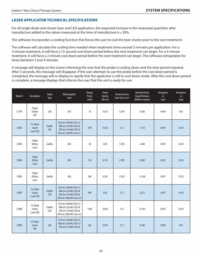
For all single diode and cluster laser and LED applicators, the expected increase in the measured quantities after manufacture added to the values measured at the time of manufacture is ± 20% .
The software incorporates a cooling function that forces the user to cool the laser cluster prior to the next treatment .
The software will calculate the cooling time needed when treatment times exceed 3 minutes per application . For a 3 minute treatment, it will force a 15 second cool down period before the next treatment can begin . For a 4 minute treatment, it will force a 2 minute cool down period before the next treatment can begin . The software extrapolates for times between 3 and 4 minutes .
A message will display on the screen informing the user that the probe is cooling down and the time period required . After 5 seconds, this message will disappear . If the user attempts to use the probe before the cool down period is completed, the message will re-display to signify that the applicator is still in cool down mode . After the cool down period is complete, a message displays that informs the user that the unit is ready for use .
LASER APPLICATOR TECHNICAL SPECIFICATIONS
SYSTEM SPECIFICATIONS
Model # DescriptionDiode Type
Wavelength(s) (nm)
Output Power (mW)
Power Density (W/cm2)
Treatment Area (Spot Size) (cm2)
Nominal Ocular Hazard Distance
(NOHD-in meters)
Divergence a1
(rad)
Divergence a1
(rad)
27799Single 670nm
LEDLED 670 10 0.012 0.785 0.386 0.698 N/A
2780233-Diode
cluster Laser/LED
GaAIAs LED
670 nm (10mW) LED x12 880 nm (25mW) LED x8 950 nm (15mW) LED x8
850 nm (50mW) Laser x5
690 0.022 31.2 3.110 0.097 0.543
27803Single 850nm Laser
GaAIAs 850 40 0.05 0.785 2.488 0.097 0.543
27804Single 850nm Laser
GaAIAs 850 150 0.191 0.785 8.800 0.097 0.543
27805Single 820nm Laser
GaAIAs 820 300 0.382 0.785 15.240 0.097 0.543
2780733-Diode
cluster Laser/LED
GaAIAs LED
670 nm (10mW) LED x12 880 nm (25mW) LED x8 950 nm (15mW) LED x8
850 nm (100mW) Laser x5
940 0.03 31.2 6.221 0.097 0.543
2780833-Diode
cluster Laser/LED
GaAIAs LED
670 nm (10mW) LED x12 880 nm (25mW) LED x8 950 nm (15mW) LED x8
850 nm (200mW) Laser x5
1440 0.045 31.2 12.443 0.097 0.543
2780933-Diode
cluster LED
LED
670 nm (10mW) LED x12 880 nm (25mW) LED x13 950 nm (15mW) LED x8
565 0.018 31.2 0.386 0.698 N/A
32
Intelect® Neo Clinical Therapy System
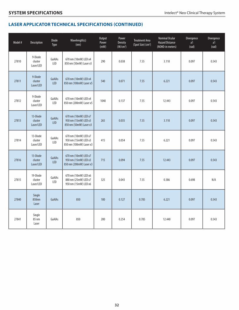
LASER APPLICATOR TECHNICAL SPECIFICATIONS (CONTINUED)
SYSTEM SPECIFICATIONS
Model # DescriptionDiode Type
Wavelength(s) (nm)
Output Power (mW)
Power Density (W/cm2)
Treatment Area (Spot Size) (cm2)
Nominal Ocular Hazard Distance
(NOHD-in meters)
Divergence a1
(rad)
Divergence a1
(rad)
278109-Diode cluster
Laser/LED
GaAIAs LED
670 nm (10mW) LED x4 850 nm (50mW) Laser x5
290 0.038 7.55 3.110 0.097 0.543
278119-Diode cluster
Laser/LED
GaAIAs LED
670 nm (10mW) LED x4 850 nm (100mW) Laser x5
540 0.071 7.55 6.221 0.097 0.543
278129-Diode cluster
Laser/LED
GaAIAs LED
670 nm (10mW) LED x4 850 nm (200mW) Laser x5
1040 0.137 7.55 12.443 0.097 0.543
2781313-Diode
cluster Laser/LED
GaAIAs LED
670 nm (10mW) LED x7 950 nm (15mW) LED x3
850 nm (50mW) Laser x3265 0.035 7.55 3.110 0.097 0.543
2781413-Diode
cluster Laser/LED
GaAIAs LED
670 nm (10mW) LED x7 950 nm (15mW) LED x3
850 nm (100mW) Laser x3415 0.054 7.55 6.221 0.097 0.543
2781613-Diode
cluster Laser/LED
GaAIAs LED
670 nm (10mW) LED x7 950 nm (15mW) LED x3
850 nm (200mW) Laser x3715 0.094 7.55 12.443 0.097 0.543
2781519-Diode
cluster Laser/LED
GaAIAs LED
670 nm (10mW) LED x6 880 nm (25mW) LED x7 950 nm (15mW) LED x6
325 0.043 7.55 0.386 0.698 N/A
27840Single 850nm Laser
GaAIAs 850 100 0.127 0.785 6.221 0.097 0.543
27841Single 85 nm Laser
GaAIAs 850 200 0.254 0.785 12.440 0.097 0.543
33
Intelect® Neo Clinical Therapy System SYSTEM SPECIFICATIONS
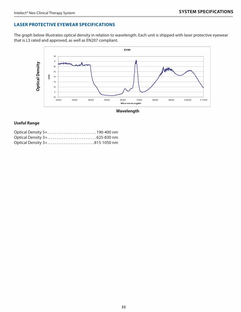
The graph below illustrates optical density in relation to wavelength . Each unit is shipped with laser protective eyewear that is L3 rated and approved, as well as EN207 compliant .
Opt
ical
Den
sity
Wavelength
Useful Range
Optical Density 5+ . . . . . . . . . . . . . . . . . . . . . . . . . . . 190-400 nm Optical Density 3+ . . . . . . . . . . . . . . . . . . . . . . . . . . . 625-830 nm Optical Density 3+ . . . . . . . . . . . . . . . . . . . . . . . . . .815-1050 nm
LASER PROTECTIVE EYEWEAR SPECIFICATIONS
34
Intelect® Neo Clinical Therapy System
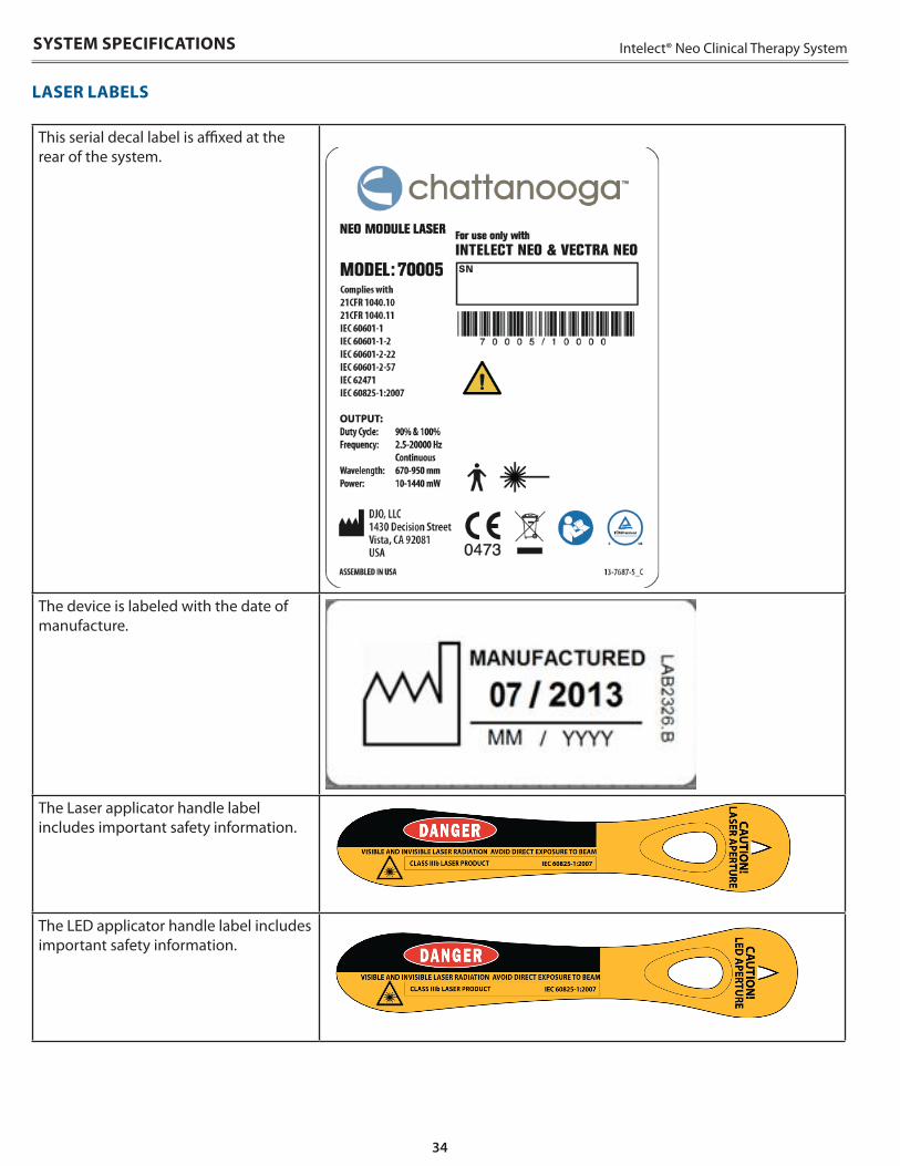
LASER LABELS
This serial decal label is affixed at the rear of the system .
The device is labeled with the date of manufacture .
The Laser applicator handle label includes important safety information .
The LED applicator handle label includes important safety information .
SYSTEM SPECIFICATIONS
35
Intelect® Neo Clinical Therapy System
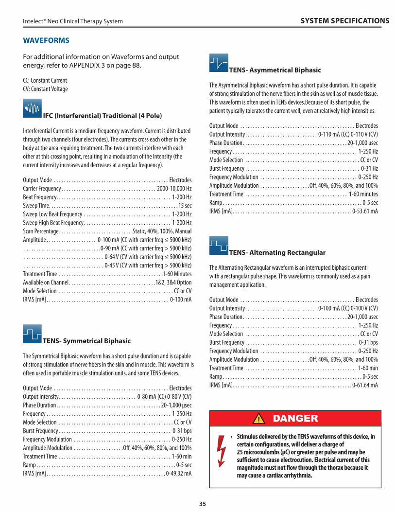
For additional information on Waveforms and output energy, refer to APPENDIX 3 on page 88 .
CC: Constant Current CV: Constant Voltage
IFC (Interferential) Traditional (4 Pole)
Interferential Current is a medium frequency waveform. Current is distributed through two channels (four electrodes). The currents cross each other in the body at the area requiring treatment. The two currents interfere with each other at this crossing point, resulting in a modulation of the intensity (the current intensity increases and decreases at a regular frequency).
Output Mode . . . . . . . . . . . . . . . . . . . . . . . . . . . . . . . . . . . . . . . . . . . . . . Electrodes Carrier Frequency . . . . . . . . . . . . . . . . . . . . . . . . . . . . . . . . . . . . . . 2000-10,000 Hz Beat Frequency. . . . . . . . . . . . . . . . . . . . . . . . . . . . . . . . . . . . . . . . . . . . . . 1-200 Hz Sweep Time. . . . . . . . . . . . . . . . . . . . . . . . . . . . . . . . . . . . . . . . . . . . . . . . . . . . 15 sec Sweep Low Beat Frequency . . . . . . . . . . . . . . . . . . . . . . . . . . . . . . . . . . . 1-200 Hz Sweep High Beat Frequency. . . . . . . . . . . . . . . . . . . . . . . . . . . . . . . . . . . 1-200 Hz Scan Percentage. . . . . . . . . . . . . . . . . . . . . . . . . . . . . .Static, 40%, 100%, Manual Amplitude. . . . . . . . . . . . . . . . . . . . 0-100 mA (CC with carrier freq ≤ 5000 kHz) . . . . . . . . . . . . . . . . . . . . . . . . . . . . . . .0-90 mA (CC with carrier freq > 5000 kHz) . . . . . . . . . . . . . . . . . . . . . . . . . . . . . . . . 0-64 V (CV with carrier freq ≤ 5000 kHz) . . . . . . . . . . . . . . . . . . . . . . . . . . . . . . . . 0-45 V (CV with carrier freq > 5000 kHz) Treatment Time . . . . . . . . . . . . . . . . . . . . . . . . . . . . . . . . . . . . . . . . . .1-60 Minutes Available on Channel. . . . . . . . . . . . . . . . . . . . . . . . . . . . . . . . . . .1&2, 3&4 Option Mode Selection . . . . . . . . . . . . . . . . . . . . . . . . . . . . . . . . . . . . . . . . . . . . . . CC or CV IRMS [mA]. . . . . . . . . . . . . . . . . . . . . . . . . . . . . . . . . . . . . . . . . . . . . . . . . 0-100 mA
TENS- Symmetrical Biphasic
The Symmetrical Biphasic waveform has a short pulse duration and is capable of strong stimulation of nerve fibers in the skin and in muscle. This waveform is often used in portable muscle stimulation units, and some TENS devices.
Output Mode . . . . . . . . . . . . . . . . . . . . . . . . . . . . . . . . . . . . . . . . . . . . . . Electrodes Output Intensity. . . . . . . . . . . . . . . . . . . . . . . . . . . . . . . 0-80 mA (CC) 0-80 V (CV) Phase Duration. . . . . . . . . . . . . . . . . . . . . . . . . . . . . . . . . . . . . . . . . . 20-1,000 µsec Frequency . . . . . . . . . . . . . . . . . . . . . . . . . . . . . . . . . . . . . . . . . . . . . . . . . . 1-250 Hz Mode Selection . . . . . . . . . . . . . . . . . . . . . . . . . . . . . . . . . . . . . . . . . . . . . . CC or CV Burst Frequency . . . . . . . . . . . . . . . . . . . . . . . . . . . . . . . . . . . . . . . . . . . . . 0-31 bps Frequency Modulation . . . . . . . . . . . . . . . . . . . . . . . . . . . . . . . . . . . . . . . 0-250 Hz Amplitude Modulation . . . . . . . . . . . . . . . . . . . .Off, 40%, 60%, 80%, and 100% Treatment Time . . . . . . . . . . . . . . . . . . . . . . . . . . . . . . . . . . . . . . . . . . . . . 1-60 min Ramp . . . . . . . . . . . . . . . . . . . . . . . . . . . . . . . . . . . . . . . . . . . . . . . . . . . . . . . . 0-5 sec IRMS [mA]. . . . . . . . . . . . . . . . . . . . . . . . . . . . . . . . . . . . . . . . . . . . . . . . 0-49.32 mA
TENS- Asymmetrical Biphasic
The Asymmetrical Biphasic waveform has a short pulse duration. It is capable of strong stimulation of the nerve fibers in the skin as well as of muscle tissue. This waveform is often used in TENS devices.Because of its short pulse, the patient typically tolerates the current well, even at relatively high intensities.
Output Mode . . . . . . . . . . . . . . . . . . . . . . . . . . . . . . . . . . . . . . . . . . . . . . Electrodes Output Intensity. . . . . . . . . . . . . . . . . . . . . . . . . . . . . 0-110 mA (CC) 0-110 V (CV) Phase Duration. . . . . . . . . . . . . . . . . . . . . . . . . . . . . . . . . . . . . . . . . . 20-1,000 µsec Frequency . . . . . . . . . . . . . . . . . . . . . . . . . . . . . . . . . . . . . . . . . . . . . . . . . . 1-250 Hz Mode Selection . . . . . . . . . . . . . . . . . . . . . . . . . . . . . . . . . . . . . . . . . . . . . . CC or CV Burst Frequency . . . . . . . . . . . . . . . . . . . . . . . . . . . . . . . . . . . . . . . . . . . . . . 0-31 Hz Frequency Modulation . . . . . . . . . . . . . . . . . . . . . . . . . . . . . . . . . . . . . . . 0-250 Hz Amplitude Modulation . . . . . . . . . . . . . . . . . . . .Off, 40%, 60%, 80%, and 100% Treatment Time . . . . . . . . . . . . . . . . . . . . . . . . . . . . . . . . . . . . . . . . . 1-60 minutes Ramp . . . . . . . . . . . . . . . . . . . . . . . . . . . . . . . . . . . . . . . . . . . . . . . . . . . . . . . . 0-5 sec IRMS [mA]. . . . . . . . . . . . . . . . . . . . . . . . . . . . . . . . . . . . . . . . . . . . . . . . 0-53.61 mA
TENS- Alternating Rectangular
The Alternating Rectangular waveform is an interrupted biphasic current with a rectangular pulse shape. This waveform is commonly used as a pain management application.
Output Mode . . . . . . . . . . . . . . . . . . . . . . . . . . . . . . . . . . . . . . . . . . . . . . Electrodes Output Intensity. . . . . . . . . . . . . . . . . . . . . . . . . . . . . 0-100 mA (CC) 0-100 V (CV) Phase Duration. . . . . . . . . . . . . . . . . . . . . . . . . . . . . . . . . . . . . . . . . . 20-1,000 µsec Frequency . . . . . . . . . . . . . . . . . . . . . . . . . . . . . . . . . . . . . . . . . . . . . . . . . . 1-250 Hz Mode Selection . . . . . . . . . . . . . . . . . . . . . . . . . . . . . . . . . . . . . . . . . . . . . . CC or CV Burst Frequency . . . . . . . . . . . . . . . . . . . . . . . . . . . . . . . . . . . . . . . . . . . . . 0-31 bps Frequency Modulation . . . . . . . . . . . . . . . . . . . . . . . . . . . . . . . . . . . . . . . 0-250 Hz Amplitude Modulation . . . . . . . . . . . . . . . . . . . .Off, 40%, 60%, 80%, and 100% Treatment Time . . . . . . . . . . . . . . . . . . . . . . . . . . . . . . . . . . . . . . . . . . . . . 1-60 min Ramp . . . . . . . . . . . . . . . . . . . . . . . . . . . . . . . . . . . . . . . . . . . . . . . . . . . . . . . . 0-5 sec IRMS [mA]. . . . . . . . . . . . . . . . . . . . . . . . . . . . . . . . . . . . . . . . . . . . . . . . 0-61.64 mA
• Stimulus delivered by the TENS waveforms of this device, in certain configurations, will deliver a charge of 25 microcoulombs (µC) or greater per pulse and may be sufficient to cause electrocution. Electrical current of this magnitude must not flow through the thorax because it may cause a cardiac arrhythmia.
DANGER
SYSTEM SPECIFICATIONS
WAVEFORMS
36
Intelect® Neo Clinical Therapy SystemSYSTEM SPECIFICATIONS
WAVEFORMS (CONTINUED)
TENS- Monophasic Rectangular
The Monophasic Rectangular waveform is an interrupted unidirectional current with a rectangular pulse shape. This waveform is commonly used with electrodiagnostic testing and clinically to stimulate denervated muscle.
Output Mode . . . . . . . . . . . . . . . . . . . . . . . . . . . . . . . . . . . . . . . . . . . . . . Electrodes Output Intensity. . . . . . . . . . . . . . . . . . . . . . . . . . . . . 0-110 mA (CC) 0-110 V (CV) Phase Duration. . . . . . . . . . . . . . . . . . . . . . . . . . . . . . . . Adjustable 20-1,000 µsec Frequency . . . . . . . . . . . . . . . . . . . . . . . . . . . . . . . . . . . . . . . . . . . . . . . . . . 1-250 Hz Mode Selection . . . . . . . . . . . . . . . . . . . . . . . . . . . . . . . . . . . . . . . . . . . . . . CC or CV Burst Frequency . . . . . . . . . . . . . . . . . . . . . . . . . . . . . . . . . . . . . . . . . . . . . 0-31 bps Frequency Modulation . . . . . . . . . . . . . . . . . . . . . . . . . . . . . . . . . . . . . . . 0-250 Hz Amplitude Modulation . . . . . . . . . . . . . . . . . . . . Off, 40%, 60%, 80%.and 100% Treatment Time . . . . . . . . . . . . . . . . . . . . . . . . . . . . . . . . . . . . . . . . . 1-60 minutes Ramp . . . . . . . . . . . . . . . . . . . . . . . . . . . . . . . . . . . . . . . . . . . . . . . . . . . . . . . . 0-5 sec IRMS [mA]. . . . . . . . . . . . . . . . . . . . . . . . . . . . . . . . . . . . . . . . . . . . . . . . 0-47.95 mA
TENS - HAN
The HAN Waveform provides optimal parameters with a precisely controlled sequence of Dense-and-Disperse (DD) modes of stimulation where 2 Hz is alternating with 15 or 70 Hz, each lasting for 3 seconds. Under these parameters all 3 kinds of opioid peptides are released simultaneously. This produces a synergistic analgesic effect for faster, greater and more long-lasting results.
Output Mode . . . . . . . . . . . . . . . . . . . . . . . . . . . . . . . . . . . . . . . . . . . . . . Electrodes Output Intensity. . . . . . . . . . . . . . . . . . . . . . . . . . . . . . . . . . . . . . . . 0-100 mA (CC) Phase Duration . . . . . . . . . . . . . . . . . . . . . . . . . . . . . . . . . . . . . . . . . . . . . .180 μsec Mode Selection . . . . . . . . . . . . . . . . . . . . . . . . . . . . . . . . . . . . . . . . . . . . . . . . . . . CC Burst Frequency . . . . . . . . . . . . . . . . . . . . . . . . . . . . . . . . . . . . . . . . . . . . . . . 0-2 Hz Frequency Modulation . . . . . . . . . . . . . . . . . . . . . . . . . . . . . . . . . . . . . . . . . . 80 Hz Cycle Time . . Burst of 8 pulses at 80 Hz(at a frequency of 2 Hz) for 3 seconds to 80 Hz continuous (no burst) for 3 seconds, repeated Treatment Time . . . . . . . . . . . . . . . . . . . . . . . . . . . . . . . . . . . . . . . . . . . . . 1-60 min Available on Channels . . . . . . . . . . . . . . . . . . . . . . . . . . . . . . . . . . . . . . 1, 2, 3, or 4 IRMS [mA]. . . . . . . . . . . . . . . . . . . . . . . . . . . . . . . . . . . . . . . . . . . . . . . . 0-20.36 mA
VMS™
VMS is a symmetrical biphasic waveform with a 100 µsec interphase interval. Because the pulse is relatively short, the waveform has a low skin load, making it suitable for applications requiring high intensities, such as in muscle strengthening protocols.
Output Mode . . . . . . . . . . . . . . . . . . . . . . . . . . . . . . . . . . . . . . . . . . . . . . Electrodes Output Intensity. . . . . . . . . . . . . . . . . . . . . . . . . . . . . 0-200 mA (CC) 0-200 V (CV) Channel Mode . . . . . . . . . . . . . . . . . . . . . . . . . . . .Single, Reciprocal, Co-Contract Phase Duration. . . . . . . . . . . . . . . . . . . . . . . . . . . . . . . . . . . . . . . . . . 20-1,000 µsec Mode Selection . . . . . . . . . . . . . . . . . . . . . . . . . . . . . . . . . . . . . . . . . . . . . . CC or CV Anti-Fatigue . . . . . . . . . . . . . . . . . . . . . . . . . . . . . . . . . . . . . . . . . . . . . . . . Off or On Set Intensity . . . . . . . . . . . . . . . . . . . . . . . Individual Channel Intensity Setting in . . . . . . . . . . . . . . . . . . . . . . . . . . . . . . . . . . . . . Reciprocal and Co-Contract modes Cycle Time . . . . . . . . . . . . . . . . . . . . . . . . . . . . . . . . . . Continuous or User Defined Frequency . . . . . . . . . . . . . . . . . . . . . . . . . . . . . . . . . . . . . . . . . . . . . . . . . 1-200 pps Ramp . . . . . . . . . . . . . . . . . . . . . . . . . . . . . . . . . . . . . . . . . . . . . . . . . . . . . . . . 0-5 sec Treatment Time . . . . . . . . . . . . . . . . . . . . . . . . . . . . . . . . . . . . . . . . . . . . . 1-60 min Available on Channels . . . . . . . . . . . . . . . . . . . . . . . . . . . . . . . . . . . . . . 1, 2, 3, or 4 IRMS [mA]. . . . . . . . . . . . . . . . . . . . . . . . . . . . . . . . . . . . . . . . . . . . . . . . . . .0-80 mA
Microcurrent
Microcurrent is a monophasic waveform of very low intensity. The literature reports beneficial effects of this waveform in the treatment of wounds. The physiological working mechanism of this effect is as yet not clearly understood. It is thought to stimulate tissue healing by stimulating the ‘current of injury’, a current which naturally occurs in healing tissue.
Output Mode . . . . . . . . . . . . . . . . . . . . . . . . . . . . . . . . . . . . . . . . . . . . . . Electrodes Output Intensity. . . . . . . . . . . . . . . . . . . . . . . . . . . . . . . . . . . . . . . . . . . 0-1,000 µA Polarity . . . . . . . . . . . . . . . . . . . . . . . . . . . . . . . .Positive, Negative, or Alternating Treatment Time . . . . . . . . . . . . . . . . . . . . . . . . . . . . . . . . . . . . . . . . . . . . . 1-60 Min Available on channels . . . . . . . . . . . . . . . . . . . . . . . . . . . . . . . . . . . . . . 1, 2, 3, or 4 Duty Cycle . . . . . . . . . . . . . . . . . . . . . . . . . . . . . . . . . . . . . . . . . . . . . . . . . . . . . . 50% Frequency . . . . . . . . . . . . . . . . . . . . . . . . . . . . . . . . . . . . . . . . . . . . . . . 0.1-1,000 Hz Mode Selection . . . . . . . . . . . . . . . . . . . . . . . . . . . . . . . . . . . . . . . . . . . . . . . . . . . CC IRMS [mA]. . . . . . . . . . . . . . . . . . . . . . . . . . . . . . . . . . . . . . . . . . . . . . . . . 0-0.71 mA
37
Intelect® Neo Clinical Therapy System SYSTEM SPECIFICATIONS
WAVEFORMS (CONTINUED)
Diadynamic Waveforms
The Diadynamic waveforms are rectified alternating currents. The alternating current is modified (rectified) to allow the current to flow in one direction only.
Output Mode . . . . . . . . . . . . . . . . . . . . . . . . . . . . . . . . . . . . . . . . . . . . . . Electrodes Output Intensity. . . . . . . . . . . . . . . . . . . . . . . . . . . . . . . . . . . . . . . . . . . . . .0-80 mA Treatment Time . . . . . . . . . . . . . . . . . . . . . . . . . . . . . . . . . . . . . . . . . . . . . 1-60 min Available on channels . . . . . . . . . . . . . . . . . . . . . . . . . . . . . . . . . . . . . . . . .1, 2, 3, 4 Mode Selection . . . . . . . . . . . . . . . . . . . . . . . . . . . . . . . . . . . . . . . . . . . . . . CC or CV
MF: (Monophasé Fixe) - Frequency of 50 Hz: phase duration of 10 ms followed by a pause of 10 ms. IRMS [mA]. . . . . . . . . . . . . . . . . . . . . . . . . . . . . . . . . . . . . . . . . . . . . . . . . . .0-40 mA
DF: (Diphasé Fixe) - Frequency of 100 Hz: phase duration of 10 ms followed immediately by another identical phase of 10 ms. CP: (Modulé en Courtes Périodes) - 1 second of MF followed abruptly by 1 second of DF. LP: (Modulé en Longues Périodes) - Rhythmical fluctuation between 2 MF currents. CP-iso: (Courtes Periodes Isodynamic) - A combination of MF and DF waveforms. CP-id: Same as CP-iso. MF+CP: A period of MF followed by a period of CP. MF+CP-id: A period of MF followed by a period of CP-ID. DF+LP: A period of DF followed by a period of LP. DF+CP: A period of DF followed by a period of CP.
IRMS [mA]. . . . . . . . . . . . . . . . . . . . . . . . . . . . . . . . . . . . . . . . . . . . . . . . 0-56.57 mA
IFC Premodulated (Traditional 2 Pole)
Premodulated Current is a medium frequency waveform. Current comes out of one channel (two electrodes). The current intensity is modulated: it increases and decreases at a regular frequency (the Amplitude Modulation Frequency).
Output Mode . . . . . . . . . . . . . . . . . . . . . . . . . . . . . . . . . . . . . . . . . . . . . . Electrodes Output Intensity. . . . . . . . . . . . . . . . . . . . . . . . . . . . . . . . . . . . . . . . . . . . . . . . . . . . . . . . . . . . . . . . .0-100 mA (CC) 0-96 V (CV) (with Carrier Frequency ≤ 5,000 kHz) . . . . . . . . . . . .0-100 mA (CC) 0-68 V (CV) (with Carrier Frequency > 5,000 kHz) Carrier Frequency . . . . . . . . . . . . . . . . . . . . . . . . . . . . . . . . . . . . . .2,000-10,000 Hz Beat Fixed (Sweep Off) . . . . . . . . . . . . . . . . . . . . . . . . . . . . . . . . . . . . . . . 1-200 Hz Sweep Low Beat Frequency . . . . . . . . . . . . . . . . . . . . . . . . . . . . . . . . . . . 1-200 Hz Sweep High Beat Frequency. . . . . . . . . . . . . . . . . . . . . . . . . . . . . . . . . . . 2-200 Hz Cycle Time . . . . . . . . . . . . . . . . . . . . . . . . . . . . . . . . . . Continuous or User Defined Mode Selection . . . . . . . . . . . . . . . . . . . . . . . . . . . . . . . . . . . . . . . . . . . . . . CC or CV Treatment Time . . . . . . . . . . . . . . . . . . . . . . . . . . . . . . . . . . . . . . . . . . . . . 1-60 Min Available on Channel. . . . . . . . . . . . . . . . . . . . . . . . . . . . . . . . . . . . . . . 1, 2, 3, or 4
Russian
Russian Current is a sinusoidal waveform, delivered in bursts or series of pulses. This method was claimed by its author (Kots) to produce maximal muscle strengthening effects without significant discomfort to the patient.
Output Mode . . . . . . . . . . . . . . . . . . . . . . . . . . . . . . . . . . . . . . . . . . . . . . Electrodes Output Intensity. . . . . . . . . . . . . . . . . . . . . . . . . . . . . . 0-100 mA (CC) 0-90 V (CV) Channel Mode . . . . . . . . . . . . . . . . . . . . . . . . . . . .Single, Reciprocal, Co-Contract Duty Cycle . . . . . . . . . . . . . . . . . . . . . . . . . . . . . . . . . . 10%, 20%, 30%, 40%, 50% Mode Selection . . . . . . . . . . . . . . . . . . . . . . . . . . . . . . . . . . . . . . . . . . . . . . CC or CV Anti-Fatigue . . . . . . . . . . . . . . . . . . . . . . . . . . . . . . . . . . . . . . . . . . . . . . . . Off or On Cycle Time . . . . . . . . . . . . . . . . . . . . . . . . . . . . . . . . . . Continuous or User Defined Carrier Frequency . . . . . . . . . . . . . . . . . . . . . . . . . . . . . . . . . . . . . . . . . . . . .2,500 Hz Burst Frequency (Anti-Fatigue Off) . . . . . . . . . . . . . . . . . . . . . . . . . . . 20-100 bps Ramp . . . . . . . . . . . . . . . . . . . . . . . . . . . . . . . . . . . . . . . . . . . . . . . . . . . . . . . . 0-5 sec Treatment Time . . . . . . . . . . . . . . . . . . . . . . . . . . . . . . . . . . . . . . . . . . . . . 1-60 min Available on Channels . . . . . . . . . . . . . . . . . . . . . . . . . . . . . . . . . . . . . . 1, 2, 3, or 4 IRMS [mA]. . . . . . . . . . . . . . . . . . . . . . . . . . . . . . . . . . . . . . . . . . . . . . . . . . .0-50 mA
VMS™ Burst
VMS Burst is a symmetrical biphasic waveform delivered in a burst format. Because the pulse is relatively short, the waveform has a low skin load, making it suitable for applications requiring high intensities, such as muscle strengthening protocols.
Output Mode . . . . . . . . . . . . . . . . . . . . . . . . . . . . . . . . . . . . . . . . . . . . . . Electrodes Output Intensity. . . . . . . . . . . . . . . . . . . . . . . . . . . . . 0-200 mA (CC) 0-200 V (CV) Channel Mode . . . . . . . . . . . . . . . . . . . . . . . . . . . .Single, Reciprocal, Co-Contract Phase Duration. . . . . . . . . . . . . . . . . . . . . . . . . . . . . . . . . . . . . . . . . . . .20-700 µsec Mode Selection . . . . . . . . . . . . . . . . . . . . . . . . . . . . . . . . . . . . . . . . . . . . . . CC or CV Anti-Fatigue . . . . . . . . . . . . . . . . . . . . . . . . . . . . . . . . . . . . . . . . . . . . . . . . Off or On Set Intensity . . . . . . . . . . . . . . . . . . . . . . . Individual Channel Intensity Setting in . . . . . . . . . . . . . . . . . . . . . . . . . . . . . . . . . . . . . Reciprocal and Co-Contract modes Cycle Time . . . . . . . . . . . . . . . . . . . . . . . . . . . . . . . . . . Continuous or User Defined Frequency . . . . . . . . . . . . . . . . . . . . . . . . . . . . . . . . . . . . . . . . . . . . . . . . . 1-200 bps Ramp . . . . . . . . . . . . . . . . . . . . . . . . . . . . . . . . . . . . . . . . . . . . . . . . . . . . . . . . 0-5 sec Treatment Time . . . . . . . . . . . . . . . . . . . . . . . . . . . . . . . . . . . . . . . . . . . . . 1-60 min Available on Channels . . . . . . . . . . . . . . . . . . . . . . . . . . . . . . . . . . . . . . 1, 2, 3, or 4 IRMS [mA]. . . . . . . . . . . . . . . . . . . . . . . . . . . . . . . . . . . . . . . . . . . . . . .0-138.56 mA
38
Intelect® Neo Clinical Therapy SystemSYSTEM SPECIFICATIONS
MONOPHASIC: Monophasic Rectangular Pulsed
The Monophasic Rectangular Pulsed waveform is an interrupted unidirectional current with a rectangular pulse shape.
Output Mode . . . . . . . . . . . . . . . . . . . . . . . . . . . . . . . . . . . . . . . . . . . . . . Electrodes Output Intensity. . . . . . . . . . . . . . . . . . . . . . . . . . . . . . . . . . . . . . . . . . . . . .0-80 mA Phase Duration. . . . . . . . . . . . . . . . . . . . . . . . . . . . . . . . . . . . . . . . . . 0.1-500.0 ms Phase Interval. . . . . . . . . . . . . . . . . . . . . . . . . . . . . . . . . . . . . . . . . . . . . 5-5,000 ms Treatment Time . . . . . . . . . . . . . . . . . . . . . . . . . . . . . . . . . . . . . . . . . . . . . 1-60 min Available on Channels . . . . . . . . . . . . . . . . . . . . . . . . . . . . . . . . . . . . . . 1, 2, 3, or 4 Mode Selection . . . . . . . . . . . . . . . . . . . . . . . . . . . . . . . . . . . . . . . . . . . . . . . . . . . CC IRMS [mA]. . . . . . . . . . . . . . . . . . . . . . . . . . . . . . . . . . . . . . . . . . . . . . . . 0-79.60 mA
MONOPHASIC: Monophasic Triangular Pulsed
The Monophasic Triangular Pulsed waveform is an interrupted unidirectional current with a triangular pulse shape.
Output Mode . . . . . . . . . . . . . . . . . . . . . . . . . . . . . . . . . . . . . . . . . . . . . . Electrodes Output Intensity. . . . . . . . . . . . . . . . . . . . . . . . . . . . . . . . . . . . . . . . . . . . . 0-80 mA Phase Duration. . . . . . . . . . . . . . . . . . . . . . . . . . . . . . . . . . . . . . . . . . 0.1-500.0 ms Phase Interval. . . . . . . . . . . . . . . . . . . . . . . . . . . . . . . . . . . . . . . . . . . . . 5-5,000 ms Treatment Time . . . . . . . . . . . . . . . . . . . . . . . . . . . . . . . . . . . . . . . . . . . . . 1-60 min Available on Channels . . . . . . . . . . . . . . . . . . . . . . . . . . . . . . . . . . . . . . 1, 2, 3, or 4 Mode Selection . . . . . . . . . . . . . . . . . . . . . . . . . . . . . . . . . . . . . . . . . . . . . . . . . . . CC IRMS [mA]. . . . . . . . . . . . . . . . . . . . . . . . . . . . . . . . . . . . . . . . . . . . . . . . 0-45.96 mA
GALVANIC: Continuous
Galvanic Current is a direct current flowing in one direction only. The current can be continuous or interrupted.
Output Mode . . . . . . . . . . . . . . . . . . . . . . . . . . . . . . . . . . . . . . . . . . . . . . Electrodes Output Intensity. . . . . . . . . . . . . . . . . . . . . . . . . . . . . . . . . . . . . . . . . . . . . .0-72 mA Polarity Reversal. . . . . . . . . . . . . . . . . . . . . . . . . . . . . . . . . . . . . . . . . . . . . On or Off . . . . . . . . . . With Polarity Reversal On, Polarity will change every five minutes. Cycle Time . . . . . . . . . . . . . . .Continuous, 5/5, 4/12, 10/10, 10/20, 10/30, 10/50 Treatment Time . . . . . . . . . . . . . . . . . . . . . . . . . . . . . . . . . . . . . . . . . . . . . 1-60 min Available on Channels . . . . . . . . . . . . . . . . . . . . . . . . . . . . . . . . . . . . . . 1, 2, 3, or 4 Mode Selection . . . . . . . . . . . . . . . . . . . . . . . . . . . . . . . . . . . . . . . . . . . . . . . . . . . CC IRMS [mA]. . . . . . . . . . . . . . . . . . . . . . . . . . . . . . . . . . . . . . . . . . . . . . . . . . .0-80 mA
WAVEFORMS (CONTINUED)
GALVANIC: Interrupted
Galvanic Current is a direct current flowing in one direction only. The current can be continuous or interrupted.
Pulse Duration . . . . . . . . . . . . . . . . . . . . . . . . . . . . . . . . . . . . . . . . . . . . . 135.5 µsec Output Mode . . . . . . . . . . . . . . . . . . . . . . . . . . . . . . . . . . . . . . . . . . . . . . Electrodes Output Intensity. . . . . . . . . . . . . . . . . . . . . . . . . . . . . . . . . . . . . . . . . . . . . .0-79 mA Polarity Reversal. . . . . . . . . . . . . . . . . . . . . . . . . . . . . . . . . . . . . . . . . . . . . On or Off . . . . . . . . . . With Polarity Reversal On, Polarity will change every five minutes. Cycle Time . . . . . . . . . . . . . . .Continuous, 5/5, 4/12, 10/10, 10/20, 10/30, 10/50 Treatment Time . . . . . . . . . . . . . . . . . . . . . . . . . . . . . . . . . . . . . . . . . . . . . 1-60 min Available on Channels . . . . . . . . . . . . . . . . . . . . . . . . . . . . . . . . . . . . . . 1, 2, 3, or 4 Ramp . . . . . . . . . . . . . . . . . . . . . . . . . . . . . . . . . . . . . . . . . . . . . . . . . . . . . . . . 0-5 sec Mode Selection . . . . . . . . . . . . . . . . . . . . . . . . . . . . . . . . . . . . . . . . . . . . . . . . . . . CC IRMS [mA]. . . . . . . . . . . . . . . . . . . . . . . . . . . . . . . . . . . . . . . . . . . . . . . . 0-73.40 mA
Träbert (Ultrareiz)
The Träbert Current is a monophasic waveform with a phase duration of 2 ms and a pause of 5 ms resulting in a frequency of approximately 143Hz.
Output Mode . . . . . . . . . . . . . . . . . . . . . . . . . . . . . . . . . . . . . . . . . . . . . . Electrodes Output Intensity. . . . . . . . . . . . . . . . . . . . . . . . . . . . . . . . . . . . . . . . . . . . . .0-80 mA Polarity Reversal. . . . . . . . . . . . . . . . . . . . . . . . . . . . . . . . . . . . . . . . . . . . . On or Off . . . . . . . . . . With Polarity Reversal On, Polarity will change every 7.5 minutes. Treatment Time . . . . . . . . . . . . . . . . . . . . . . . . . . . . . . . . . . . . . . . . . . . . . 1-60 min Available on Channels . . . . . . . . . . . . . . . . . . . . . . . . . . . . . . . . . . . . . . 1, 2, 3, or 4 Frequency.. . . . . . . . . . . . . . . . . . . . . . . . . . . . . . . . . . . . . . . . . . . . . . . . . 142.86 Hz Phase Duration. . . . . . . . . . . . . . . . . . . . . . . . . . . . . . . . . . . . . . . . . . . . . . . . . . 2 ms Mode Selection . . . . . . . . . . . . . . . . . . . . . . . . . . . . . . . . . . . . . . . . . . . . . . . . . . . CC IRMS [mA]. . . . . . . . . . . . . . . . . . . . . . . . . . . . . . . . . . . . . . . . . . . . . . . . 0-42.76 mA
39
Intelect® Neo Clinical Therapy System SYSTEM SPECIFICATIONS
SURGED: Monophasic Rectangular
The SURGED: Monophasic Rectangular Current is a series of rectangular, monophasic pulses. The pulses surge to maximum power, hold and then decrease before the pause. This waveform is well suited for muscle strengthening.
Output Mode . . . . . . . . . . . . . . . . . . . . . . . . . . . . . . . . . . . . . . . . . . . . . . Electrodes Output Intensity. . . . . . . . . . . . . . . . . . . . . . . . . . . . . . . . . . . . . . . . . . . . . .0-80 mA Phase Duration. . . . . . . . . . . . . . . . . . . . . . . . . . . . . . . . . . . . . . . . . . . . . 0.2-5.0 ms Frequency . . . . . . . . . . . . . . . . . . . . . . . . . . . . . . . . . . . . . . . . . . . . . . . . . . . 5-60 Hz Surges per minute . . . . . . . . . . . . . . . . . . . . . . . . . . . . . . . . . . . . . . . . . . . . . . . 1-20 Pause . . . . . . . . . . . . . . . . . . . . . . . . . . . . . . . . . . . . . . . . . . . . . . . . . . . . . . . 0-57 sec Treatment Time . . . . . . . . . . . . . . . . . . . . . . . . . . . . . . . . . . . . . . . . . . . . . 1-60 min Available on Channels . . . . . . . . . . . . . . . . . . . . . . . . . . . . . . . . . . . . . . 1, 2, 3, or 4 Mode Selection . . . . . . . . . . . . . . . . . . . . . . . . . . . . . . . . . . . . . . . . . . . . . . . . . . . CC IRMS [mA]. . . . . . . . . . . . . . . . . . . . . . . . . . . . . . . . . . . . . . . . . . . . . . . . 0-43.82 mA
SURGED: Monophasic Triangular
The SURGED: Monophasic Triangular Current is a series of triangular, monophasic pulses. The pulses surge to maximum power, hold and then decrease before the pause. This waveform is well suited for muscle strengthening.
Output Mode . . . . . . . . . . . . . . . . . . . . . . . . . . . . . . . . . . . . . . . . . . . . . . Electrodes Output Intensity. . . . . . . . . . . . . . . . . . . . . . . . . . . . . . . . . . . . . . . . . . . . . .0-80 mA Phase Duration. . . . . . . . . . . . . . . . . . . . . . . . . . . . . . . . . . . . . . . . . . . . . 0.2-5.0 ms Frequency . . . . . . . . . . . . . . . . . . . . . . . . . . . . . . . . . . . . . . . . . . . . . . . . . . . 5-60 Hz Surges per minute . . . . . . . . . . . . . . . . . . . . . . . . . . . . . . . . . . . . . . . . . . . . . . . 1-20 Pause . . . . . . . . . . . . . . . . . . . . . . . . . . . . . . . . . . . . . . . . . . . . . . . . . . . . . . . 0-57 sec Treatment Time . . . . . . . . . . . . . . . . . . . . . . . . . . . . . . . . . . . . . . . . . . . . . 1-60 min Available on Channels . . . . . . . . . . . . . . . . . . . . . . . . . . . . . . . . . . . . . . 1, 2, 3, or 4 Mode Selection . . . . . . . . . . . . . . . . . . . . . . . . . . . . . . . . . . . . . . . . . . . . . . . . . . . CC IRMS [mA[. . . . . . . . . . . . . . . . . . . . . . . . . . . . . . . . . . . . . . . . . . . . . . . . 0-25.30 mA
VMS™ FR
The VMS-FR version of the VMS waveform is a physiologically based channel interaction in which one channel stimulates the agonist and the other the antagonist of the muscle group that is being exercised. The agonistic channel initiates the movement with a brief burst of power, followed by a period of sustained activity to complete the movement. The antagonistic channel has a brief burst of power to slow down the initial acceleration of the agonist, followed by a low output to regulate the movement of the agonist. The movement is completed by a final burst of activity in both channels. VMS is a symmetrical biphasic waveform with a 100 μsec interphase interval. Because the pulse is relatively short, the waveform has a low skin load, making it suitable for applications requiring high intensities, such as in muscle strengthening protocols.
Output Mode . . . . . . . . . . . . . . . . . . . . . . . . . . . . . . . . . . . . . . . . . . . . . . Electrodes Output Intensity. . . . . . . . . . . . . . . . . . . . . . . . . . . . . 0-150 mA (CC) 0-150 V (CV) Burst Duration . . . . . . . . . . . . . . . . . . . . . . . . . . . . . . . . . . . . . . . . . .200 - 5000 ms Phase Duration . . . . . . . . . . . . . . . . . . . . . . . . . . . . . . . . . . . . . . . . . . .20-400 μsec Mode Selection . . . . . . . . . . . . . . . . . . . . . . . . . . . . . . . . . . . . . . . . . . . . . . CC or CV Channel Intensity. . . . . . . . . . . . . Setting in Reciprocal and Co-Contract modes Cycle Time . . . . . . . . . . . . . . . Continuous, 5/5, 4/12,10/10, 10/20, 10/30, 10/50 Frequency . . . . . . . . . . . . . . . . . . . . . . . . . . . . . . . . . . . . . . . . . . . . . . . . . 20-80 pps Treatment Time . . . . . . . . . . . . . . . . . . . . . . . . . . . . . . . . . . . . . . . . . . . . . 1-60 min Available on Channels . . . . . . . . . . . . . . . . . . . . . . . . . . . . . . . . . . . . . . . . 1&2, 3&4 IRMS [mA]. . . . . . . . . . . . . . . . . . . . . . . . . . . . . . . . . . . . . . . . . . . . . . . . 0-20.57 mA
High Voltage Pulsed Current (HVPC)
The High Voltage Pulsed Current (HVPC) has a very brief pulse duration characterized by two distinct peaks delivered at high voltage. The waveform is monophasic (current flows in one direction only). The high voltage causes a decreased skin resistance making the current comfortable and easy to tolerate.
Output Mode . . . . . . . . . . . . . . . . . . . . . . . . . . . . . . . . . . . . . . . . . . . . . . Electrodes Output Intensity. . . . . . . . . . . . . . . . . . . . . . . . . . . . . . . . . . . . . . . . . . . . . . 0-500 V Polarity . . . . . . . . . . . . . . . . . . . . . . . . . . . . . . . . . . . . . . . . . . . Positive or Negative Ramp . . . . . . . . . . . . . . . . . . . . . . . . . . . . . . . . . . . . . . . . . . . . . . . . . . . . . . 0.5-5 sec Display. . . . . . . . . . . . . . . . . . . . . . . . . . . . . . . . . . . . . . . . . . . Peak Current or Volts Sweep High Frequency . . . . . . . . . . . . . . . . . . . . . . . . . . . . . . . . . . . . . 20-120 pps Sweep Low Frequency. . . . . . . . . . . . . . . . . . . . . . . . . . . . . . . . . . . . . . 10-110 pps Frequency . . . . . . . . . . . . . . . . . . . . . . . . . . . . . . . . . . . . . . . . . . . . . . . . 10-120 pps Cycle Time . . . . . . . . . . . . . . . . . . . . . . . . . . . . . . . . . . Continuous or User Defined Treatment Time . . . . . . . . . . . . . . . . . . . . . . . . . . . . . . . . . . . . . . . . . . . . . 1-60 Min Available on Channels . . . . . . . . . . . . . . . . . . . . . . . . . . . . . . . . . . . . . . 1, 2, 3, or 4 Mode Selection . . . . . . . . . . . . . . . . . . . . . . . . . . . . . . . . . . . . . . . . . . . . . . . . . . . CV
WAVEFORMS (CONTINUED)
40
Intelect® Neo Clinical Therapy System
Iontophoresis
Iontophoresis is the introduction of ionizable drugs through intact skin by the administration of continuous, direct electrical current into the tissues of the body. The medicinal substance must be placed under the electrode pole with the same charge.
The following list provides the typical dosage for common medications-solutions used in iontophoresis:
Medications – Solutions:
• Acetic acid (-): calcium deposits, calcific tendinitis. 2-5% solution• Calcium chloride (+): skeletal muscle spasm. 2% aqueous solution• Dexamethasone (-): anti-inflammatory; chronic myofascial trigger points
4mg/ml aqueous solution• Glycopyrronium Bromide (+): hyperhidrosis. 0.05% solution• Hyaluronidase (+): edema; scleroderma. Reconstitute with 0.9% sodium
chloride to provide a 150µg/ml solution.• Hydrocortisone (+): anti-inflammatory. 0.1-1% solution (ointment)• Iodine (-): sclerotic effect on scar tissue. 5-10% solution (ointment)• Lidocaine (+): local anaesthetic effect. 4% solution• Lithium (+): gouty arthritis. 2% lithium chloride solution• Magnesium sulphate (+): skeletal muscle spasm; myositis. 2% aqueous
solution or ointment• Salicylate (-): muscle and joint pain (rheumatic diseases). 2-3% sodium
salicylate solution• Sodium chloride (-): sclerotic effect on scar tissue. 1-5% solution• Zinc oxide (+): open wounds, ulcers. 20% ointment.
NOTE: Do not place electrode on open wound. Electrodes are NOT Sterile.
DC Current . . . . . . . . . . . . . . . . . . . . . . . . . . . . . . . . . . . . . . . . . . . . . . . . . . . .0-4 mA
WAVEFORMS (CONTINUED)
SYSTEM SPECIFICATIONS
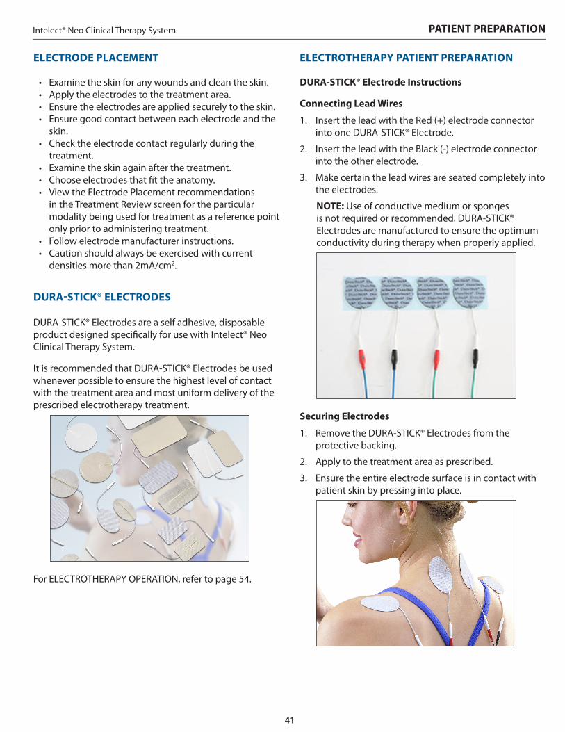
41
Intelect® Neo Clinical Therapy System
DURA-STICK® Electrode Instructions
Connecting Lead Wires
1 . Insert the lead with the Red (+) electrode connector into one DURA-STICK® Electrode .
2 . Insert the lead with the Black (-) electrode connector into the other electrode .
3 . Make certain the lead wires are seated completely into the electrodes .
NOTE: Use of conductive medium or sponges is not required or recommended . DURA-STICK® Electrodes are manufactured to ensure the optimum conductivity during therapy when properly applied .
Securing Electrodes
1 . Remove the DURA-STICK® Electrodes from the protective backing .
2 . Apply to the treatment area as prescribed .
3 . Ensure the entire electrode surface is in contact with patient skin by pressing into place .
ELECTROTHERAPY PATIENT PREPARATION
• Examine the skin for any wounds and clean the skin .• Apply the electrodes to the treatment area .• Ensure the electrodes are applied securely to the skin .• Ensure good contact between each electrode and the
skin .• Check the electrode contact regularly during the
treatment .• Examine the skin again after the treatment .• Choose electrodes that fit the anatomy .• View the Electrode Placement recommendations
in the Treatment Review screen for the particular modality being used for treatment as a reference point only prior to administering treatment .
• Follow electrode manufacturer instructions .• Caution should always be exercised with current
densities more than 2mA/cm2 .
DURA-STICK® ELECTRODES
DURA-STICK® Electrodes are a self adhesive, disposable product designed specifically for use with Intelect® Neo Clinical Therapy System .
It is recommended that DURA-STICK® Electrodes be used whenever possible to ensure the highest level of contact with the treatment area and most uniform delivery of the prescribed electrotherapy treatment .
For ELECTROTHERAPY OPERATION, refer to page 54 .
PATIENT PREPARATION
ELECTRODE PLACEMENT
42
Intelect® Neo Clinical Therapy System
IONTOPHORESIS PATIENT PREPARATION
PATIENT PREPARATION
• Appropriate skin preparation is required for adequate conduction between the skin and the electrode . Clean the skin with warm water . Do not use alcohol .
• Choose the appropriate size electrode for the body part (the larger the body part the larger the electrode required)
• Larger electrodes are more comfortable and prevent increases in current density
• Apply medicinal substance directly on skin (ointment) or on gauze between skin and electrode, or inject in iontophoresis electrode
• Attach the treating electrode over the treatment area• Return electrode should be separated by at least the
diameter of the active electrode • Dupel B .L .U .E . iontophoresis electrodes ordering
information: - 199332-001 Small (1 .5cc fill) - 199334-001 Butterfly (2 .0cc fill) - 199335-001 Standard (2 .5cc fill) - 199336-001 Large (4 .0cc fill) - 1336 Black Snap Adapters (2 pin to snap
adapters)
For IONTOPHORESIS OPERATION, refer to page 59 .
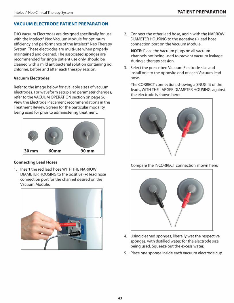
43
Intelect® Neo Clinical Therapy System
DJO Vacuum Electrodes are designed specifically for use with the Intelect® Neo Vacuum Module for optimum efficiency and performance of the Intelect® Neo Therapy System . These electrodes are multi-use when properly maintained and cleaned . The associated sponges are recommended for single patient use only, should be cleaned with a mild antibacterial solution containing no chlorine, before and after each therapy session .
Vacuum Electrodes
Refer to the image below for available sizes of vacuum electrodes . For waveform setup and parameter changes, refer to the VACUUM OPERATION section on page 56 . View the Electrode Placement recommendations in the Treatment Review Screen for the particular modality being used for prior to administering treatment .
connect sEMG lead
wires
Connecting Lead Hoses
1 . Insert the red lead hose WITH THE NARROW DIAMETER HOUSING to the positive (+) lead hose connection port for the channel desired on the Vacuum Module .
VACUUM ELECTRODE PATIENT PREPARATION
PATIENT PREPARATION
2 . Connect the other lead hose, again with the NARROW DIAMETER HOUSING to the negative (-) lead hose connection port on the Vacuum Module .
NOTE: Place the Vacuum plugs on all vacuum channels not being used to prevent vacuum leakage during a therapy session .
3 . Select the prescribed Vacuum Electrode size and install one to the opposite end of each Vacuum lead hose .
The CORRECT connection, showing a SNUG fit of the leads, WITH THE LARGER DIAMETER HOUSING, against the electrode is shown here:
Compare the INCORRECT connection shown here:
.
4 . Using cleaned sponges, liberally wet the respective sponges, with distilled water, for the electrode size being used . Squeeze out the excess water .
5 . Place one sponge inside each Vacuum electrode cup .
30 mm 60mm 90 mm

44
Intelect® Neo Clinical Therapy System
6 . Turn “ON” the Vacuum at the Treatment Review Screen .
7 . Select Vacuum Mode: In continuous mode, the vacuum unit will maintain the desired vacuum pressure .
8 . With the Vacuum Electrodes placed face down on a clean, firm surface, increase the intensity of the Vacuum with the Vacuum Intensity Knob until the electrodes are secure on the surface . Individually remove each electrode from the surface and place on the treatment area of the patient, as prescribed .
NOTE: Adjust Vacuum intensity until Vacuum Electrodes are secure to patient .
NOTE: Do not use Vacuum Electrodes with sEMG, sEMG+STIM waveforms and Iontophoresis .
For VACUUM OPERATION, refer to page 56 .
PATIENT PREPARATION
VACUUM ELECTRODE PATIENT PREPARATION (CONTINUED)
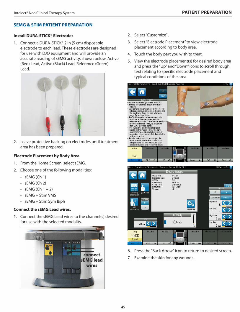
45
Intelect® Neo Clinical Therapy System
SEMG & STIM PATIENT PREPARATION
Install DURA-STICK® Electrodes
1 . Connect a DURA-STICK® 2 in (5 cm) disposable electrode to each lead . These electrodes are designed for use with DJO equipment and will provide an accurate reading of sEMG activity, shown below . Active (Red) Lead, Active (Black) Lead, Reference (Green) Lead .
2 . Leave protective backing on electrodes until treatment area has been prepared .
Electrode Placement by Body Area
1 . From the Home Screen, select sEMG .
2 . Choose one of the following modalities:
• sEMG (Ch 1)• sEMG (Ch 2)• sEMG (Ch 1 + 2)• sEMG + Stim VMS• sEMG + Stim Sym Biph
Connect the sEMG Lead wires .
1 . Connect the sEMG Lead wires to the channel(s) desired for use with the selected modality .
connect sEMG lead
wires
2 . Select “Customize” .
3 . Select “Electrode Placement” to view electrode placement according to body area .
4 . Touch the body part you wish to treat .
5 . View the electrode placement(s) for desired body area and press the “Up” and “Down” icons to scroll through text relating to specific electrode placement and typical conditions of the area .
6 . Press the “Back Arrow” icon to return to desired screen .
7 . Examine the skin for any wounds .
PATIENT PREPARATION
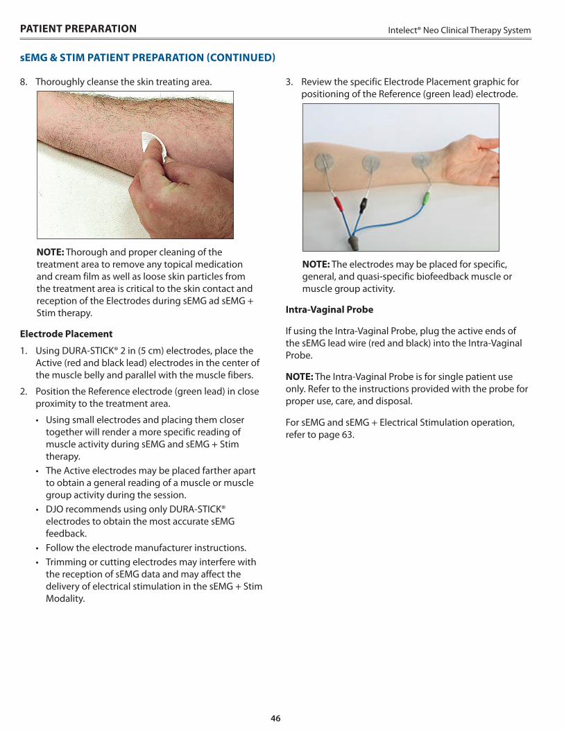
46
Intelect® Neo Clinical Therapy SystemPATIENT PREPARATION
sEMG & STIM PATIENT PREPARATION (CONTINUED)
3 . Review the specific Electrode Placement graphic for positioning of the Reference (green lead) electrode .
NOTE: The electrodes may be placed for specific, general, and quasi-specific biofeedback muscle or muscle group activity .
Intra-Vaginal Probe
If using the Intra-Vaginal Probe, plug the active ends of the sEMG lead wire (red and black) into the Intra-Vaginal Probe .
NOTE: The Intra-Vaginal Probe is for single patient use only . Refer to the instructions provided with the probe for proper use, care, and disposal .
For sEMG and sEMG + Electrical Stimulation operation, refer to page 63 .
8 . Thoroughly cleanse the skin treating area .
NOTE: Thorough and proper cleaning of the treatment area to remove any topical medication and cream film as well as loose skin particles from the treatment area is critical to the skin contact and reception of the Electrodes during sEMG ad sEMG + Stim therapy .
Electrode Placement
1 . Using DURA-STICK® 2 in (5 cm) electrodes, place the Active (red and black lead) electrodes in the center of the muscle belly and parallel with the muscle fibers .
2 . Position the Reference electrode (green lead) in close proximity to the treatment area .
• Using small electrodes and placing them closer together will render a more specific reading of muscle activity during sEMG and sEMG + Stim therapy .
• The Active electrodes may be placed farther apart to obtain a general reading of a muscle or muscle group activity during the session .
• DJO recommends using only DURA-STICK® electrodes to obtain the most accurate sEMG feedback .
• Follow the electrode manufacturer instructions .• Trimming or cutting electrodes may interfere with
the reception of sEMG data and may affect the delivery of electrical stimulation in the sEMG + Stim Modality .
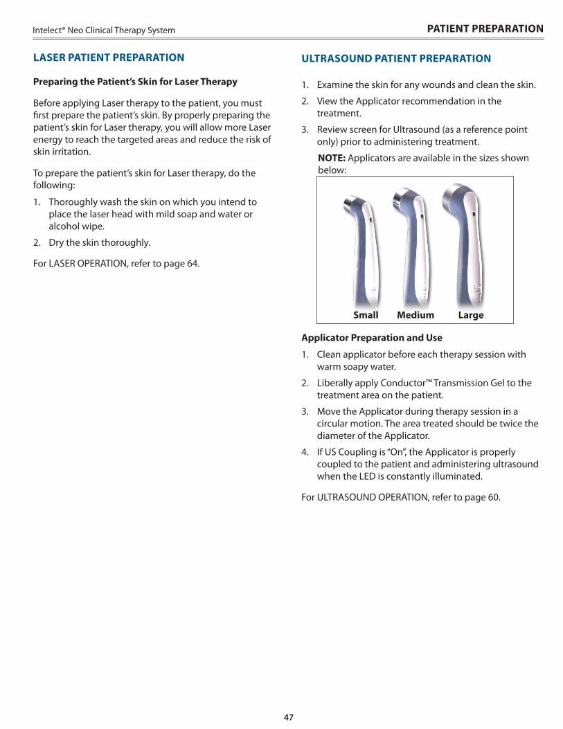
47
Intelect® Neo Clinical Therapy System PATIENT PREPARATION
ULTRASOUND PATIENT PREPARATION
1 . Examine the skin for any wounds and clean the skin .
2 . View the Applicator recommendation in the treatment .
3 . Review screen for Ultrasound (as a reference point only) prior to administering treatment .
NOTE: Applicators are available in the sizes shown below:
Applicator Preparation and Use
1 . Clean applicator before each therapy session with warm soapy water .
2 . Liberally apply Conductor™ Transmission Gel to the treatment area on the patient .
3 . Move the Applicator during therapy session in a circular motion . The area treated should be twice the diameter of the Applicator .
4 . If US Coupling is “On”, the Applicator is properly coupled to the patient and administering ultrasound when the LED is constantly illuminated .
For ULTRASOUND OPERATION, refer to page 60 .
Preparing the Patient’s Skin for Laser Therapy
Before applying Laser therapy to the patient, you must first prepare the patient’s skin . By properly preparing the patient’s skin for Laser therapy, you will allow more Laser energy to reach the targeted areas and reduce the risk of skin irritation .
To prepare the patient’s skin for Laser therapy, do the following:
1 . Thoroughly wash the skin on which you intend to place the laser head with mild soap and water or alcohol wipe .
2 . Dry the skin thoroughly .
For LASER OPERATION, refer to page 64 .
LASER PATIENT PREPARATION
Small Medium Large
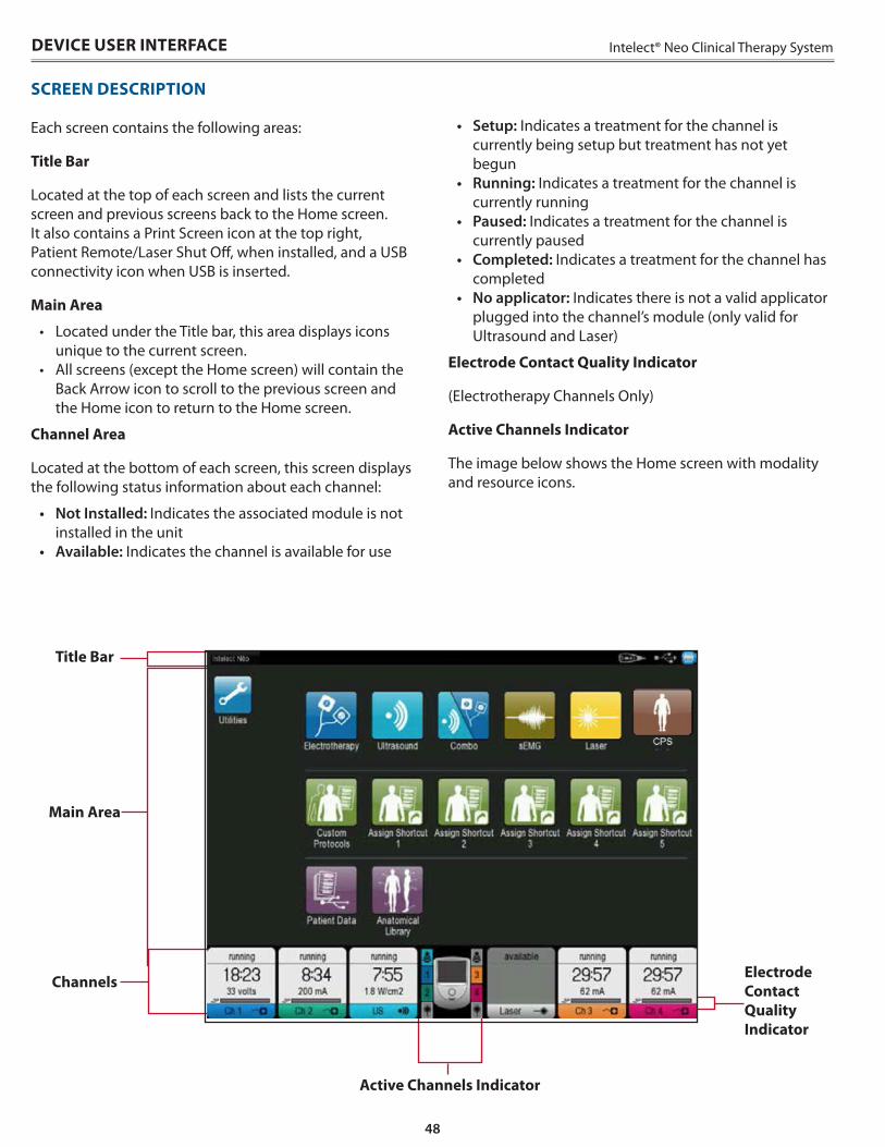
48
Intelect® Neo Clinical Therapy SystemDEVICE USER INTERFACE
SCREEN DESCRIPTION
Each screen contains the following areas:
Title Bar
Located at the top of each screen and lists the current screen and previous screens back to the Home screen . It also contains a Print Screen icon at the top right, Patient Remote/Laser Shut Off, when installed, and a USB connectivity icon when USB is inserted .
Main Area
• Located under the Title bar, this area displays icons unique to the current screen .
• All screens (except the Home screen) will contain the Back Arrow icon to scroll to the previous screen and the Home icon to return to the Home screen .
Channel Area
Located at the bottom of each screen, this screen displays the following status information about each channel:
• Not Installed: Indicates the associated module is not installed in the unit
• Available: Indicates the channel is available for use
• Setup: Indicates a treatment for the channel is currently being setup but treatment has not yet begun
• Running: Indicates a treatment for the channel is currently running
• Paused: Indicates a treatment for the channel is currently paused
• Completed: Indicates a treatment for the channel has completed
• No applicator: Indicates there is not a valid applicator plugged into the channel’s module (only valid for Ultrasound and Laser)
Electrode Contact Quality Indicator
(Electrotherapy Channels Only)
Active Channels Indicator
The image below shows the Home screen with modality and resource icons .
Title Bar
Main Area
Channels
Active Channels Indicator
Electrode Contact Quality Indicator
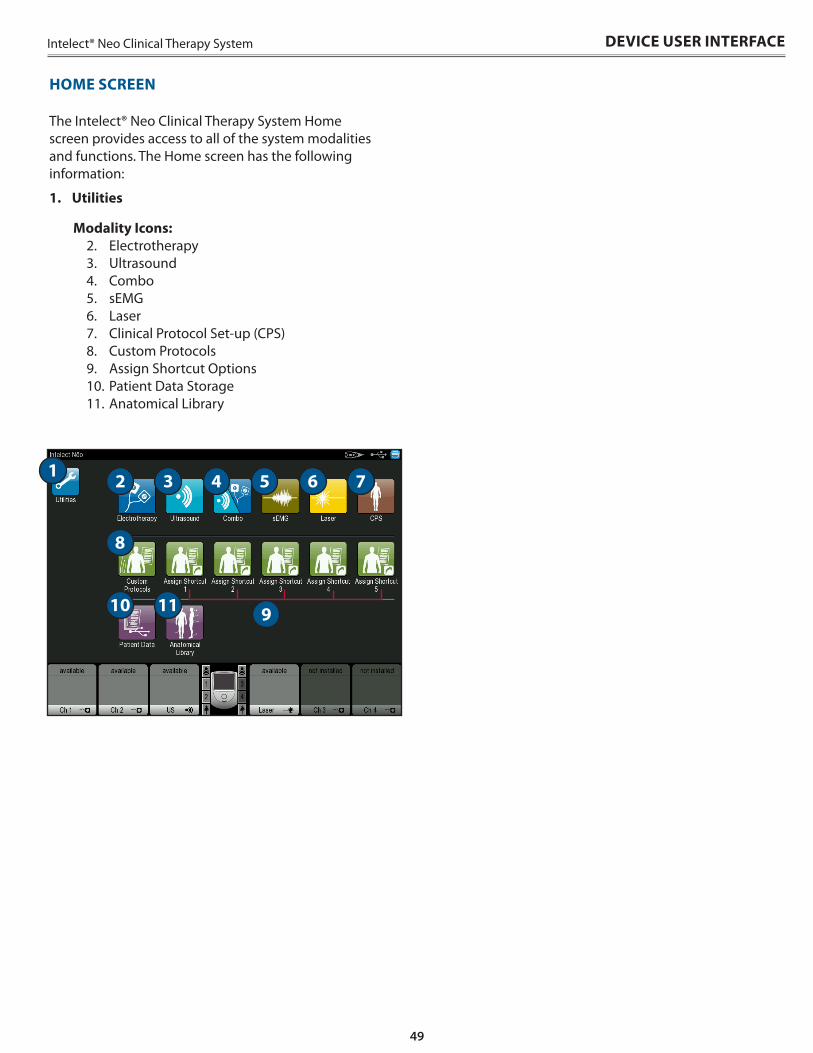
49
Intelect® Neo Clinical Therapy System DEVICE USER INTERFACE
HOME SCREEN
The Intelect® Neo Clinical Therapy System Home screen provides access to all of the system modalities and functions . The Home screen has the following information:
1 . Utilities
Modality Icons:2 . Electrotherapy3 . Ultrasound4 . Combo5 . sEMG6 . Laser7 . Clinical Protocol Set-up (CPS)8 . Custom Protocols 9 . Assign Shortcut Options10 . Patient Data Storage11 . Anatomical Library
1 2 3 4 5 6
1110
8
7
9
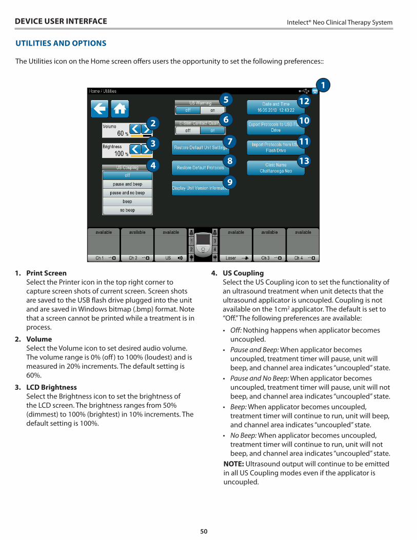
50
Intelect® Neo Clinical Therapy System
1 . Print Screen Select the Printer icon in the top right corner to capture screen shots of current screen . Screen shots are saved to the USB flash drive plugged into the unit and are saved in Windows bitmap ( .bmp) format . Note that a screen cannot be printed while a treatment is in process .
2 . Volume Select the Volume icon to set desired audio volume . The volume range is 0% (off ) to 100% (loudest) and is measured in 20% increments . The default setting is 60% .
3 . LCD Brightness Select the Brightness icon to set the brightness of the LCD screen . The brightness ranges from 50% (dimmest) to 100% (brightest) in 10% increments . The default setting is 100% .
4 . US Coupling Select the US Coupling icon to set the functionality of an ultrasound treatment when unit detects that the ultrasound applicator is uncoupled . Coupling is not available on the 1cm2 applicator . The default is set to “Off .” The following preferences are available:
• Off: Nothing happens when applicator becomes uncoupled .
• Pause and Beep: When applicator becomes uncoupled, treatment timer will pause, unit will beep, and channel area indicates “uncoupled” state .
• Pause and No Beep: When applicator becomes uncoupled, treatment timer will pause, unit will not beep, and channel area indicates “uncoupled” state .
• Beep: When applicator becomes uncoupled, treatment timer will continue to run, unit will beep, and channel area indicates “uncoupled” state .
• No Beep: When applicator becomes uncoupled, treatment timer will continue to run, unit will not beep, and channel area indicates “uncoupled” state .
NOTE: Ultrasound output will continue to be emitted in all US Coupling modes even if the applicator is uncoupled .
15
6
7
8
9
12
10
11
13
2
3
4
UTILITIES AND OPTIONS
The Utilities icon on the Home screen offers users the opportunity to set the following preferences::
DEVICE USER INTERFACE
51
Intelect® Neo Clinical Therapy System
5 . US Head Warming Select the US Head Warming icon to turn on or off the ultrasound warming feature during ultrasound treatment setup . The available choices are either “On” or “Off” . The default setting is “Off .”
6 . E-Stim Contact Quality Select the <E-Stim Contact Quality> icon to turn on or off the electrotherapy contact quality monitoring function . The available choices are either “On” or “Off .” The default setting is “On,” and in the “On” position, the unit will monitor the contact quality of the electrodes on all waveforms, excluding High Volt and Microcurrent .
NOTE: If the impedance feedback exceeds 5000 ohms (tolerance +/-20%) and the set intensity is ≥ 10 mA CC or 10 V CV, then the unit will display an information message and set the intensity to zero for all channels associated with this treatment .
7 . Restore Default Unit Settings Select the <Restore Default> Unit Settings icon to reset all of the following settings back to their factory defaults:
• Volume• LCD Brightness• US Coupling• US Head Warming
8 . Restore Default Protocols Select the <Restore Default Protocols> icon to reset all protocols (factory, custom, and the 5 custom protocol shortcuts) to their factory defaults .
9 . Display Unit Version Information Select the <Display Unit Version Information> icon to view the install status of each module . For all installed modules, the PCB information and the Software version for that module is displayed .
If a valid software upgrade USB flash drive is inserted into the unit, the version of software for each module that is on the USB flash drive is displayed .
NOTE: USB flash drive version is displayed in yellow if it is newer than the current software version for the applicable module .
10 . Export Protocols to USB flash drive Select the Export Protocols to USB flash drive icon to export all protocols (both default and custom) to a valid USB flash drive .
UTILITIES AND OPTIONS (CONTINUED)
11 . Import Protocols from USB Flash Drive Select the Import Protocols from USB flash drive icon to import all protocols from a valid USB flash drive . Files exported from a differently configured (e .g ., Vectra® Neo vs Intelect® Neo) unit will not be imported . Any protocols with the same name as an existing unit protocol will be overwritten by the imported protocol, and any protocols of a different name on the unit will remain intact .
12 . Date and Time Select the Date and Time icon to set the date and time on the unit .
13 . Clinic Name Select the <Clinic Name> icon to enter the name of your clinic . The clinic displays on the Home Screen and on the patient treatment reports saved to the USB flash drive . The following buttons will perform the functions listed:
• Left – Moves the cursor to the left one space per instance pressed .
• Right – Moves the cursor to the right one space per instance pressed .
• Space – Inserts one space per instance pressed .• Clear – Clears the entire entry .• Delete – Once the cursor has been moved using the
Left or Right icons, press the Delete icon to delete the character .
• Caps – Press the Caps icon to capitalize the letters or to make letters lower case .
• Cancel – Press the Cancel icon to cancel the clinic name entry function and return to the Utilities screen .
• Accept – Press the Accept icon once entry of the clinic name is complete . The clinic name should now appear in the title bar area of the screen .
DEVICE USER INTERFACE
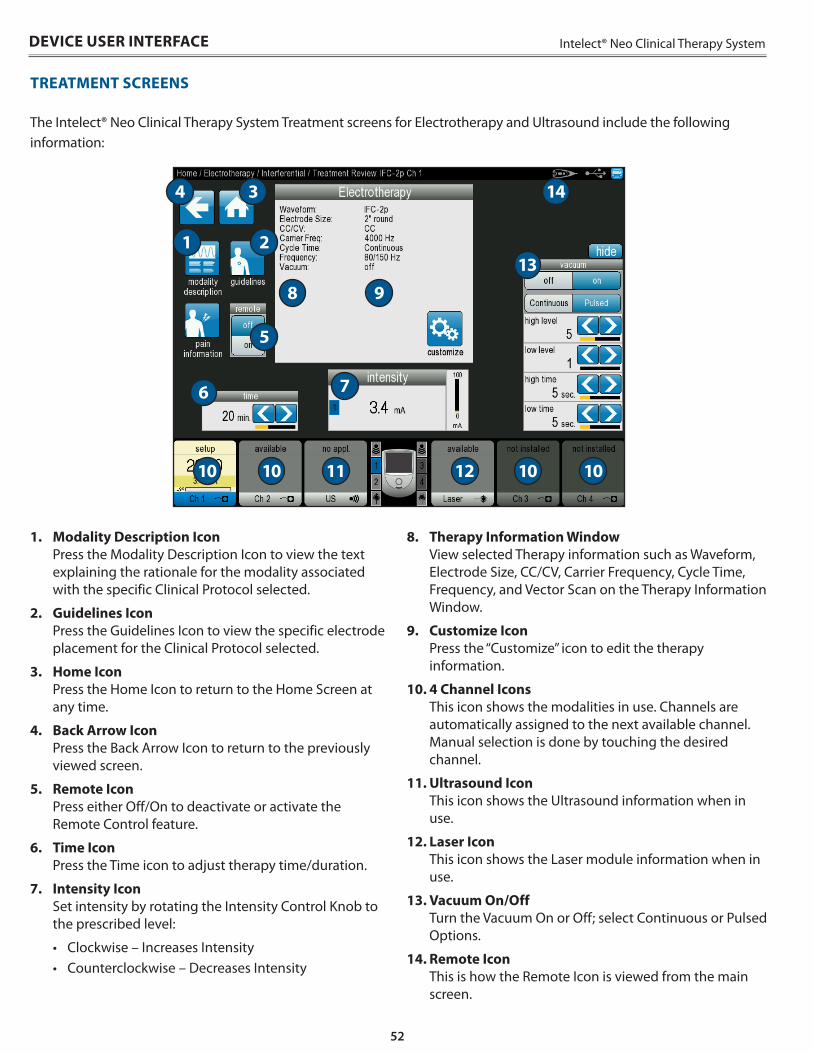
52
Intelect® Neo Clinical Therapy SystemDEVICE USER INTERFACE
TREATMENT SCREENS
The Intelect® Neo Clinical Therapy System Treatment screens for Electrotherapy and Ultrasound include the following information:
1 . Modality Description Icon Press the Modality Description Icon to view the text explaining the rationale for the modality associated with the specific Clinical Protocol selected .
2 . Guidelines Icon Press the Guidelines Icon to view the specific electrode placement for the Clinical Protocol selected .
3 . Home Icon Press the Home Icon to return to the Home Screen at any time .
4 . Back Arrow Icon Press the Back Arrow Icon to return to the previously viewed screen .
5 . Remote Icon Press either Off/On to deactivate or activate the Remote Control feature .
6 . Time Icon Press the Time icon to adjust therapy time/duration .
7 . Intensity Icon Set intensity by rotating the Intensity Control Knob to the prescribed level:
• Clockwise – Increases Intensity• Counterclockwise – Decreases Intensity
8 . Therapy Information Window View selected Therapy information such as Waveform, Electrode Size, CC/CV, Carrier Frequency, Cycle Time, Frequency, and Vector Scan on the Therapy Information Window .
9 . Customize Icon Press the “Customize” icon to edit the therapy information .
10 . 4 Channel Icons This icon shows the modalities in use . Channels are automatically assigned to the next available channel . Manual selection is done by touching the desired channel .
11 . Ultrasound Icon This icon shows the Ultrasound information when in use .
12 . Laser Icon This icon shows the Laser module information when in use .
13 . Vacuum On/Off Turn the Vacuum On or Off; select Continuous or Pulsed Options .
14 . Remote Icon This is how the Remote Icon is viewed from the main screen .
1
6
10 10 11 12 10 10
14
5
8 9
7
2
4 3
13
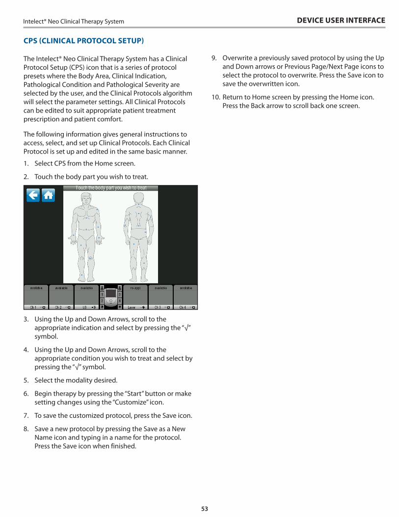
53
Intelect® Neo Clinical Therapy System
CPS (CLINICAL PROTOCOL SETUP)
The Intelect® Neo Clinical Therapy System has a Clinical Protocol Setup (CPS) icon that is a series of protocol presets where the Body Area, Clinical Indication, Pathological Condition and Pathological Severity are selected by the user, and the Clinical Protocols algorithm will select the parameter settings . All Clinical Protocols can be edited to suit appropriate patient treatment prescription and patient comfort .
The following information gives general instructions to access, select, and set up Clinical Protocols . Each Clinical Protocol is set up and edited in the same basic manner .
1 . Select CPS from the Home screen .
2 . Touch the body part you wish to treat .
3 . Using the Up and Down Arrows, scroll to the appropriate indication and select by pressing the “√” symbol .
4 . Using the Up and Down Arrows, scroll to the appropriate condition you wish to treat and select by pressing the “√” symbol .
5 . Select the modality desired .
6 . Begin therapy by pressing the “Start” button or make setting changes using the “Customize” icon .
7 . To save the customized protocol, press the Save icon .
8 . Save a new protocol by pressing the Save as a New Name icon and typing in a name for the protocol . Press the Save icon when finished .
DEVICE USER INTERFACE
9 . Overwrite a previously saved protocol by using the Up and Down arrows or Previous Page/Next Page icons to select the protocol to overwrite . Press the Save icon to save the overwritten icon .
10 . Return to Home screen by pressing the Home icon . Press the Back arrow to scroll back one screen .
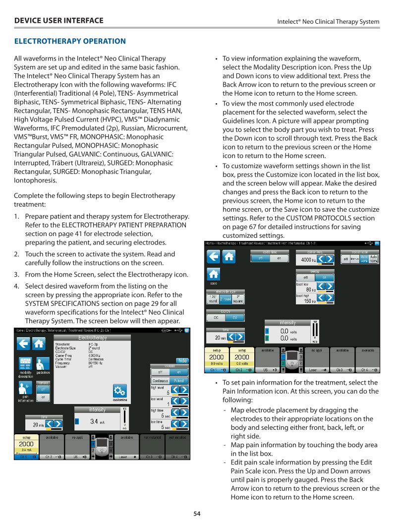
54
Intelect® Neo Clinical Therapy System
All waveforms in the Intelect® Neo Clinical Therapy System are set up and edited in the same basic fashion . The Intelect® Neo Clinical Therapy System has an Electrotherapy Icon with the following waveforms: IFC (Interferential) Traditional (4 Pole), TENS- Asymmetrical Biphasic, TENS- Symmetrical Biphasic, TENS- Alternating Rectangular, TENS- Monophasic Rectangular, TENS HAN, High Voltage Pulsed Current (HVPC), VMS™ Diadynamic Waveforms, IFC Premodulated (2p), Russian, Microcurrent, VMS™Burst, VMS™ FR, MONOPHASIC: Monophasic Rectangular Pulsed, MONOPHASIC: Monophasic Triangular Pulsed, GALVANIC: Continuous, GALVANIC: Interrupted, Träbert (Ultrareiz), SURGED: Monophasic Rectangular, SURGED: Monophasic Triangular, Iontophoresis .
Complete the following steps to begin Electrotherapy treatment:
1 . Prepare patient and therapy system for Electrotherapy . Refer to the ELECTROTHERAPY PATIENT PREPARATION section on page 41 for electrode selection, preparing the patient, and securing electrodes .
2 . Touch the screen to activate the system . Read and carefully follow the instructions on the screen .
3 . From the Home Screen, select the Electrotherapy icon .
4 . Select desired waveform from the listing on the screen by pressing the appropriate icon . Refer to the SYSTEM SPECIFICATIONS section on page 29 for all waveform specifications for the Intelect® Neo Clinical Therapy System . The screen below will then appear .
ELECTROTHERAPY OPERATION
• To view information explaining the waveform, select the Modality Description icon . Press the Up and Down icons to view additional text . Press the Back Arrow icon to return to the previous screen or the Home icon to return to the Home screen .
• To view the most commonly used electrode placement for the selected waveform, select the Guidelines Icon . A picture will appear prompting you to select the body part you wish to treat . Press the Down icon to scroll through text . Press the Back icon to return to the previous screen or the Home icon to return to the Home screen .
• To customize waveform settings shown in the list box, press the Customize icon located in the list box, and the screen below will appear . Make the desired changes and press the Back icon to return to the previous screen, the Home icon to return to the home screen, or the Save icon to save the customize settings . Refer to the CUSTOM PROTOCOLS section on page 67 for detailed instructions for saving customized settings .
• To set pain information for the treatment, select the Pain Information icon . At this screen, you can do the following:
- Map electrode placement by dragging the electrodes to their appropriate locations on the body and selecting either front, back, left, or right side .
- Map pain information by touching the body area in the list box .
- Edit pain scale information by pressing the Edit Pain Scale icon . Press the Up and Down arrows until pain is properly gauged . Press the Back Arrow icon to return to the previous screen or the Home icon to return to the Home screen .
DEVICE USER INTERFACE
55
Intelect® Neo Clinical Therapy System DEVICE USER INTERFACE
ELECTROTHERAPY OPERATION (CONTINUED)
5 . If desired, connect optional Remote Control to device .
6 . Use the Intensity dial to set therapy intensity:
• Clockwise - Increases Intensity• Counterclockwise - Decreases Intensity
7 . Press the Start button to begin therapy, the Pause button to pause treatment, or the Stop button to terminate the treatment .
NOTE: To make setting adjustments during therapy, press the Customize icon or adjust intensity using the intensity knob .
8 . When treatment has completed, the Treatment Summary screen will appear with the following options:
• Save therapy information to USB Flash Drive by inserting a USB Flash Drive into the device and pressing the Save to USB Flash Drive icon .
• Repeat the treatment by pressing the Run This Treatment icon .
• Save the treatment protocol by pressing the Save Protocol icon . Refer to the CUSTOM PROTOCOLS section on page 67 for detailed instructions on customized settings .
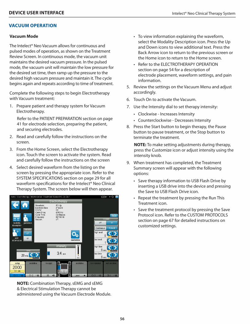
56
Intelect® Neo Clinical Therapy System
VACUUM OPERATION
DEVICE USER INTERFACE
Vacuum Mode
The Intelect® Neo Vacuum allows for continuous and pulsed modes of operation, as shown on the Treatment Review Screen . In continuous mode, the vacuum unit maintains the desired vacuum pressure . In the pulsed mode, the vacuum unit will maintain the low pressure for the desired set time, then ramp up the pressure to the desired high vacuum pressure and maintain it . The cycle begins again and repeats according to time of treatment .
Complete the following steps to begin Electrotherapy with Vacuum treatment:
1 . Prepare patient and therapy system for Vacuum Electrotherapy .
Refer to the PATIENT PREPARATION section on page 41 for electrode selection, preparing the patient, and securing electrodes .
2 . Read and carefully follow the instructions on the screen .
3 . From the Home Screen, select the Electrotherapy icon . Touch the screen to activate the system . Read and carefully follow the instructions on the screen
4 . Select desired waveform from the listing on the screen by pressing the appropriate icon . Refer to the SYSTEM SPECIFICATIONS section on page 29 for all waveform specifications for the Intelect® Neo Clinical Therapy System . The screen below will then appear .
NOTE: Combination Therapy, sEMG and sEMG & Electrical Stimulation Therapy cannot be administered using the Vacuum Electrode Module .
• To view information explaining the waveform, select the Modality Description icon . Press the Up and Down icons to view additional text . Press the Back Arrow icon to return to the previous screen or the Home icon to return to the Home screen .
• Refer to the ELECTROTHERAPY OPERATION section on page 54 for a description of electrode placement, waveform settings, and pain information .
5 . Review the settings on the Vacuum Menu and adjust accordingly .
6 . Touch On to activate the Vacuum .
7 . Use the Intensity dial to set therapy intensity:
• Clockwise - Increases Intensity• Counterclockwise - Decreases Intensity
8 . Press the Start button to begin therapy, the Pause button to pause treatment, or the Stop button to terminate the treatment .
NOTE: To make setting adjustments during therapy, press the Customize icon or adjust intensity using the intensity knob .
9 . When treatment has completed, the Treatment Summary screen will appear with the following options:
• Save therapy information to USB Flash Drive by inserting a USB drive into the device and pressing the Save to USB Flash Drive icon .
• Repeat the treatment by pressing the Run This Treatment icon .
• Save the treatment protocol by pressing the Save Protocol icon . Refer to the CUSTOM PROTOCOLS section on page 67 for detailed instructions on customized settings .
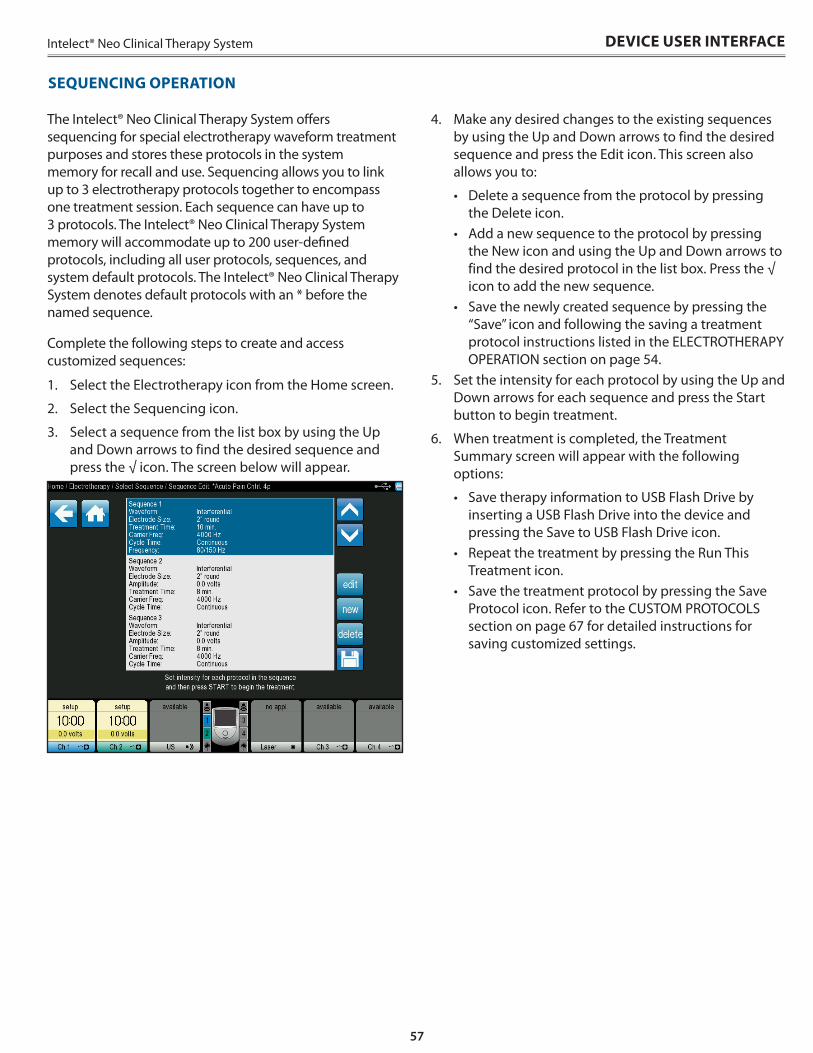
57
Intelect® Neo Clinical Therapy System
The Intelect® Neo Clinical Therapy System offers sequencing for special electrotherapy waveform treatment purposes and stores these protocols in the system memory for recall and use . Sequencing allows you to link up to 3 electrotherapy protocols together to encompass one treatment session . Each sequence can have up to 3 protocols . The Intelect® Neo Clinical Therapy System memory will accommodate up to 200 user-defined protocols, including all user protocols, sequences, and system default protocols . The Intelect® Neo Clinical Therapy System denotes default protocols with an * before the named sequence .
Complete the following steps to create and access customized sequences:
1 . Select the Electrotherapy icon from the Home screen .
2 . Select the Sequencing icon .
3 . Select a sequence from the list box by using the Up and Down arrows to find the desired sequence and press the √ icon . The screen below will appear .
DEVICE USER INTERFACE
SEQUENCING OPERATION
4 . Make any desired changes to the existing sequences by using the Up and Down arrows to find the desired sequence and press the Edit icon . This screen also allows you to:
• Delete a sequence from the protocol by pressing the Delete icon .
• Add a new sequence to the protocol by pressing the New icon and using the Up and Down arrows to find the desired protocol in the list box . Press the √ icon to add the new sequence .
• Save the newly created sequence by pressing the “Save” icon and following the saving a treatment protocol instructions listed in the ELECTROTHERAPY OPERATION section on page 54 .
5 . Set the intensity for each protocol by using the Up and Down arrows for each sequence and press the Start button to begin treatment .
6 . When treatment is completed, the Treatment Summary screen will appear with the following options:
• Save therapy information to USB Flash Drive by inserting a USB Flash Drive into the device and pressing the Save to USB Flash Drive icon .
• Repeat the treatment by pressing the Run This Treatment icon .
• Save the treatment protocol by pressing the Save Protocol icon . Refer to the CUSTOM PROTOCOLS section on page 67 for detailed instructions for saving customized settings .
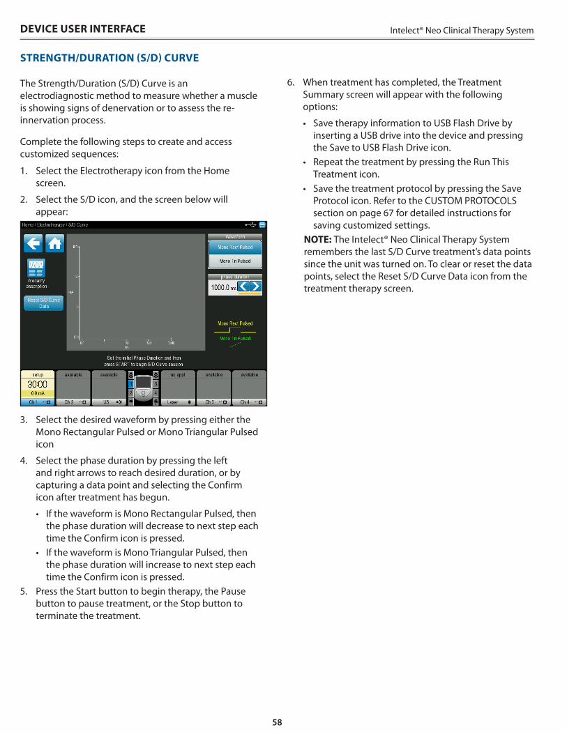
58
Intelect® Neo Clinical Therapy System
STRENGTH/DURATION (S/D) CURVE
The Strength/Duration (S/D) Curve is an electrodiagnostic method to measure whether a muscle is showing signs of denervation or to assess the re-innervation process .
Complete the following steps to create and access customized sequences:
1 . Select the Electrotherapy icon from the Home screen .
2 . Select the S/D icon, and the screen below will appear:
3 . Select the desired waveform by pressing either the Mono Rectangular Pulsed or Mono Triangular Pulsed icon
4 . Select the phase duration by pressing the left and right arrows to reach desired duration, or by capturing a data point and selecting the Confirm icon after treatment has begun .
• If the waveform is Mono Rectangular Pulsed, then the phase duration will decrease to next step each time the Confirm icon is pressed .
• If the waveform is Mono Triangular Pulsed, then the phase duration will increase to next step each time the Confirm icon is pressed .
5 . Press the Start button to begin therapy, the Pause button to pause treatment, or the Stop button to terminate the treatment .
6 . When treatment has completed, the Treatment Summary screen will appear with the following options:
• Save therapy information to USB Flash Drive by inserting a USB drive into the device and pressing the Save to USB Flash Drive icon .
• Repeat the treatment by pressing the Run This Treatment icon .
• Save the treatment protocol by pressing the Save Protocol icon . Refer to the CUSTOM PROTOCOLS section on page 67 for detailed instructions for saving customized settings .
NOTE: The Intelect® Neo Clinical Therapy System remembers the last S/D Curve treatment’s data points since the unit was turned on . To clear or reset the data points, select the Reset S/D Curve Data icon from the treatment therapy screen .
DEVICE USER INTERFACE
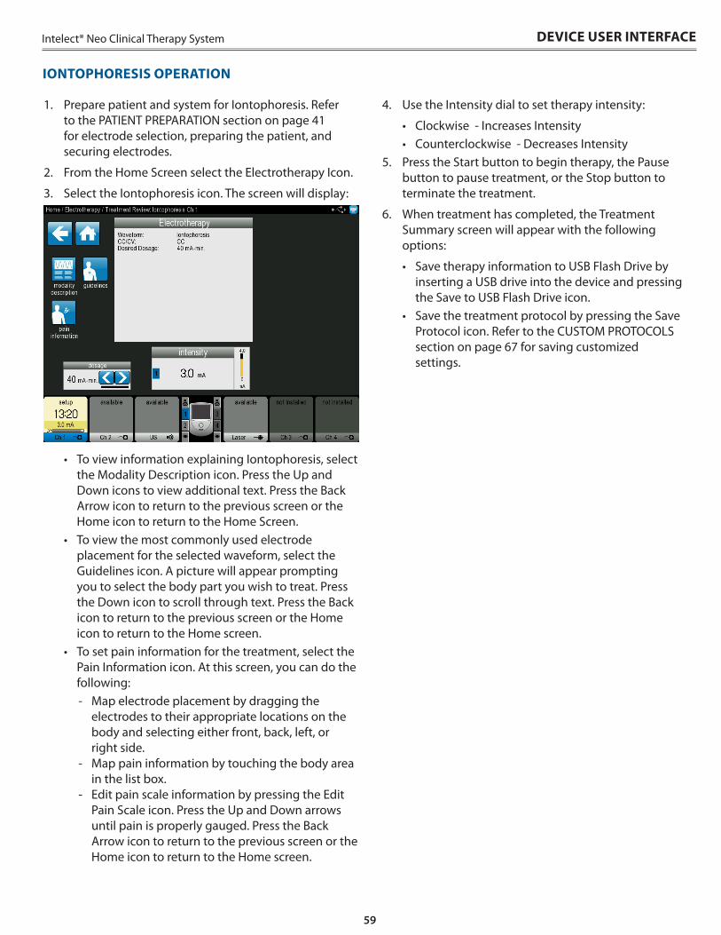
59
Intelect® Neo Clinical Therapy System DEVICE USER INTERFACE
IONTOPHORESIS OPERATION
1 . Prepare patient and system for Iontophoresis . Refer to the PATIENT PREPARATION section on page 41 for electrode selection, preparing the patient, and securing electrodes .
2 . From the Home Screen select the Electrotherapy Icon .
3 . Select the Iontophoresis icon . The screen will display:
• To view information explaining Iontophoresis, select the Modality Description icon . Press the Up and Down icons to view additional text . Press the Back Arrow icon to return to the previous screen or the Home icon to return to the Home Screen .
• To view the most commonly used electrode placement for the selected waveform, select the Guidelines icon . A picture will appear prompting you to select the body part you wish to treat . Press the Down icon to scroll through text . Press the Back icon to return to the previous screen or the Home icon to return to the Home screen .
• To set pain information for the treatment, select the Pain Information icon . At this screen, you can do the following:
- Map electrode placement by dragging the electrodes to their appropriate locations on the body and selecting either front, back, left, or right side .
- Map pain information by touching the body area in the list box .
- Edit pain scale information by pressing the Edit Pain Scale icon . Press the Up and Down arrows until pain is properly gauged . Press the Back Arrow icon to return to the previous screen or the Home icon to return to the Home screen .
4 . Use the Intensity dial to set therapy intensity:
• Clockwise - Increases Intensity• Counterclockwise - Decreases Intensity
5 . Press the Start button to begin therapy, the Pause button to pause treatment, or the Stop button to terminate the treatment .
6 . When treatment has completed, the Treatment Summary screen will appear with the following options:
• Save therapy information to USB Flash Drive by inserting a USB drive into the device and pressing the Save to USB Flash Drive icon .
• Save the treatment protocol by pressing the Save Protocol icon . Refer to the CUSTOM PROTOCOLS section on page 67 for saving customized settings .
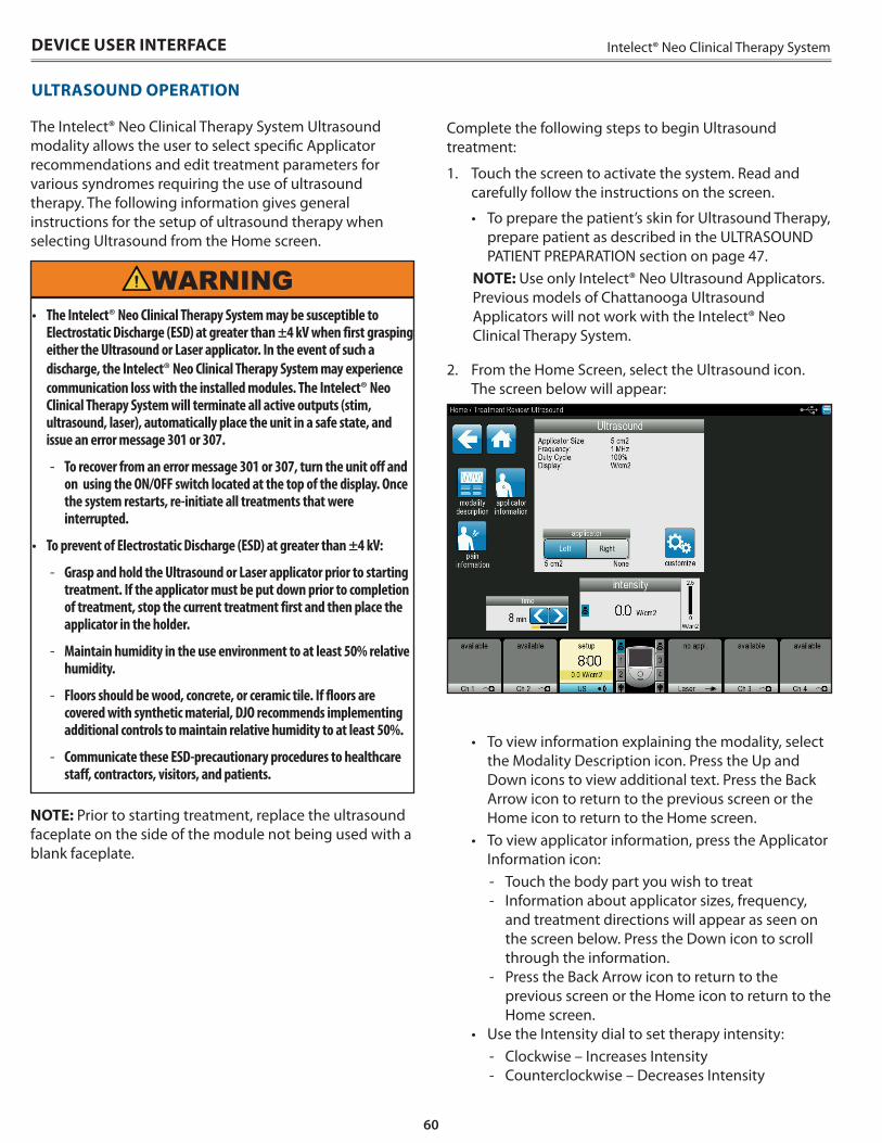
60
Intelect® Neo Clinical Therapy SystemDEVICE USER INTERFACE
The Intelect® Neo Clinical Therapy System Ultrasound modality allows the user to select specific Applicator recommendations and edit treatment parameters for various syndromes requiring the use of ultrasound therapy . The following information gives general instructions for the setup of ultrasound therapy when selecting Ultrasound from the Home screen .
WARNING• The Intelect® Neo Clinical Therapy System may be susceptible to
Electrostatic Discharge (ESD) at greater than ±4 kV when first grasping either the Ultrasound or Laser applicator. In the event of such a discharge, the Intelect® Neo Clinical Therapy System may experience communication loss with the installed modules. The Intelect® Neo Clinical Therapy System will terminate all active outputs (stim, ultrasound, laser), automatically place the unit in a safe state, and issue an error message 301 or 307.
- To recover from an error message 301 or 307, turn the unit off and on using the ON/OFF switch located at the top of the display. Once the system restarts, re-initiate all treatments that were interrupted.
• To prevent of Electrostatic Discharge (ESD) at greater than ±4 kV:
- Grasp and hold the Ultrasound or Laser applicator prior to starting treatment. If the applicator must be put down prior to completion of treatment, stop the current treatment first and then place the applicator in the holder.
- Maintain humidity in the use environment to at least 50% relative humidity.
- Floors should be wood, concrete, or ceramic tile. If floors are covered with synthetic material, DJO recommends implementing additional controls to maintain relative humidity to at least 50%.
- Communicate these ESD-precautionary procedures to healthcare staff, contractors, visitors, and patients.
NOTE: Prior to starting treatment, replace the ultrasound faceplate on the side of the module not being used with a blank faceplate .
ULTRASOUND OPERATION
Complete the following steps to begin Ultrasound treatment:
1 . Touch the screen to activate the system . Read and carefully follow the instructions on the screen .
• To prepare the patient’s skin for Ultrasound Therapy, prepare patient as described in the ULTRASOUND PATIENT PREPARATION section on page 47 .
NOTE: Use only Intelect® Neo Ultrasound Applicators . Previous models of Chattanooga Ultrasound Applicators will not work with the Intelect® Neo Clinical Therapy System .
2 . From the Home Screen, select the Ultrasound icon . The screen below will appear:
• To view information explaining the modality, select the Modality Description icon . Press the Up and Down icons to view additional text . Press the Back Arrow icon to return to the previous screen or the Home icon to return to the Home screen .
• To view applicator information, press the Applicator Information icon:
- Touch the body part you wish to treat - Information about applicator sizes, frequency,
and treatment directions will appear as seen on the screen below . Press the Down icon to scroll through the information .
- Press the Back Arrow icon to return to the previous screen or the Home icon to return to the Home screen .
• Use the Intensity dial to set therapy intensity: - Clockwise – Increases Intensity - Counterclockwise – Decreases Intensity
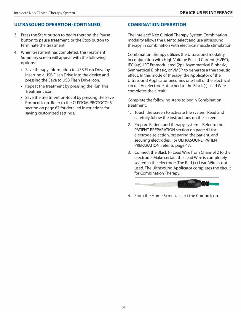
61
Intelect® Neo Clinical Therapy System DEVICE USER INTERFACE
3 . Press the Start button to begin therapy, the Pause button to pause treatment, or the Stop button to terminate the treatment .
4 . When treatment has completed, the Treatment Summary screen will appear with the following options:
• Save therapy information to USB Flash Drive by inserting a USB Flash Drive into the device and pressing the Save to USB Flash Drive icon .
• Repeat the treatment by pressing the Run This Treatment icon .
• Save the treatment protocol by pressing the Save Protocol icon . Refer to the CUSTOM PROTOCOLS section on page 67 for detailed instructions for saving customized settings .
ULTRASOUND OPERATION (CONTINUED)
The Intelect® Neo Clinical Therapy System Combination modality allows the user to select and use ultrasound therapy in combination with electrical muscle stimulation .
Combination therapy utilizes the Ultrasound modality in conjunction with High Voltage Pulsed Current (HVPC), IFC (4p), IFC Premodulated (2p), Asymmetrical Biphasic, Symmetrical Biphasic, or VMS™ to generate a therapeutic effect . In this mode of therapy, the Applicator of the Ultrasound Applicator becomes one-half of the electrical circuit . An electrode attached to the Black (-) Lead Wire completes the circuit .
Complete the following steps to begin Combination treatment:
1 . Touch the screen to activate the system . Read and carefully follow the instructions on the screen .
2 . Prepare Patient and therapy system – Refer to the PATIENT PREPARATION section on page 41 for electrode selection, preparing the patient, and securing electrodes . For ULTRASOUND PATIENT PREPARATION, refer to page 47 .
3 . Connect the Black (-) Lead Wire from Channel 2 to the electrode . Make certain the Lead Wire is completely seated in the electrode . The Red (+) Lead Wire is not used . The Ultrasound Applicator completes the circuit for Combination Therapy .
4 . From the Home Screen, select the Combo icon .
COMBINATION OPERATION
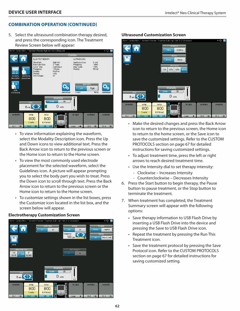
62
Intelect® Neo Clinical Therapy SystemDEVICE USER INTERFACE
5 . Select the ultrasound combination therapy desired, and press the corresponding icon . The Treatment Review Screen below will appear:
• To view information explaining the waveform, select the Modality Description icon . Press the Up and Down icons to view additional text . Press the Back Arrow icon to return to the previous screen or the Home icon to return to the Home screen .
• To view the most commonly used electrode placement for the selected waveform, select the Guidelines icon . A picture will appear prompting you to select the body part you wish to treat . Press the Down icon to scroll through text . Press the Back Arrow icon to return to the previous screen or the Home icon to return to the Home screen .
• To customize settings shown in the list boxes, press the Customize icon located in the list box, and the screen below will appear .
Electrotherapy Customization Screen
Ultrasound Customization Screen
• Make the desired changes and press the Back Arrow icon to return to the previous screen, the Home icon to return to the home screen, or the Save icon to save the customized settings . Refer to the CUSTOM PROTOCOLS section on page 67 for detailed instructions for saving customized settings .
• To adjust treatment time, press the left or right arrows to reach desired treatment time .
• Use the Intensity dial to set therapy intensity: - Clockwise – Increases Intensity - Counterclockwise – Decreases Intensity
6 . Press the Start button to begin therapy, the Pause button to pause treatment, or the Stop button to terminate the treatment .
7 . When treatment has completed, the Treatment Summary screen will appear with the following options:
• Save therapy information to USB Flash Drive by inserting a USB Flash Drive into the device and pressing the Save to USB Flash Drive icon .
• Repeat the treatment by pressing the Run This Treatment icon .
• Save the treatment protocol by pressing the Save Protocol icon . Refer to the CUSTOM PROTOCOLS section on page 67 for detailed instructions for saving customized setting .
COMBINATION OPERATION (CONTINUED)
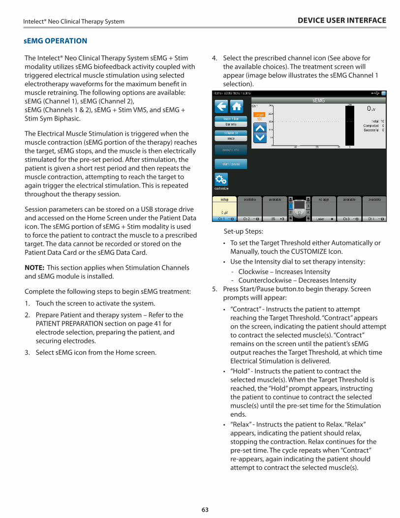
63
Intelect® Neo Clinical Therapy System
The Intelect® Neo Clinical Therapy System sEMG + Stim modality utilizes sEMG biofeedback activity coupled with triggered electrical muscle stimulation using selected electrotherapy waveforms for the maximum benefit in muscle retraining . The following options are available: sEMG (Channel 1), sEMG (Channel 2), sEMG (Channels 1 & 2), sEMG + Stim VMS, and sEMG + Stim Sym Biphasic .
The Electrical Muscle Stimulation is triggered when the muscle contraction (sEMG portion of the therapy) reaches the target, sEMG stops, and the muscle is then electrically stimulated for the pre-set period . After stimulation, the patient is given a short rest period and then repeats the muscle contraction, attempting to reach the target to again trigger the electrical stimulation . This is repeated throughout the therapy session .
Session parameters can be stored on a USB storage drive and accessed on the Home Screen under the Patient Data icon . The sEMG portion of sEMG + Stim modality is used to force the patient to contract the muscle to a prescribed target . The data cannot be recorded or stored on the Patient Data Card or the sEMG Data Card .
NOTE: This section applies when Stimulation Channels and sEMG module is installed .
Complete the following steps to begin sEMG treatment:
1 . Touch the screen to activate the system .
2 . Prepare Patient and therapy system – Refer to the PATIENT PREPARATION section on page 41 for electrode selection, preparing the patient, and securing electrodes .
3 . Select sEMG icon from the Home screen .
4 . Select the prescribed channel icon (See above for the available choices) . The treatment screen will appear (image below illustrates the sEMG Channel 1 selection) .
Set-up Steps:
• To set the Target Threshold either Automatically or Manually, touch the CUSTOMIZE Icon .
• Use the Intensity dial to set therapy intensity: - Clockwise – Increases Intensity - Counterclockwise – Decreases Intensity
5 . Press Start/Pause button .to begin therapy . Screen prompts willl appear:
• “Contract” - Instructs the patient to attempt reaching the Target Threshold . “Contract” appears on the screen, indicating the patient should attempt to contract the selected muscle(s) . “Contract” remains on the screen until the patient’s sEMG output reaches the Target Threshold, at which time Electrical Stimulation is delivered .
• “Hold” - Instructs the patient to contract the selected muscle(s) . When the Target Threshold is reached, the “Hold” prompt appears, instructing the patient to continue to contract the selected muscle(s) until the pre-set time for the Stimulation ends .
• “Relax” - Instructs the patient to Relax . “Relax” appears, indicating the patient should relax, stopping the contraction . Relax continues for the pre-set time . The cycle repeats when “Contract” re-appears, again indicating the patient should attempt to contract the selected muscle(s) .
DEVICE USER INTERFACE
sEMG OPERATION
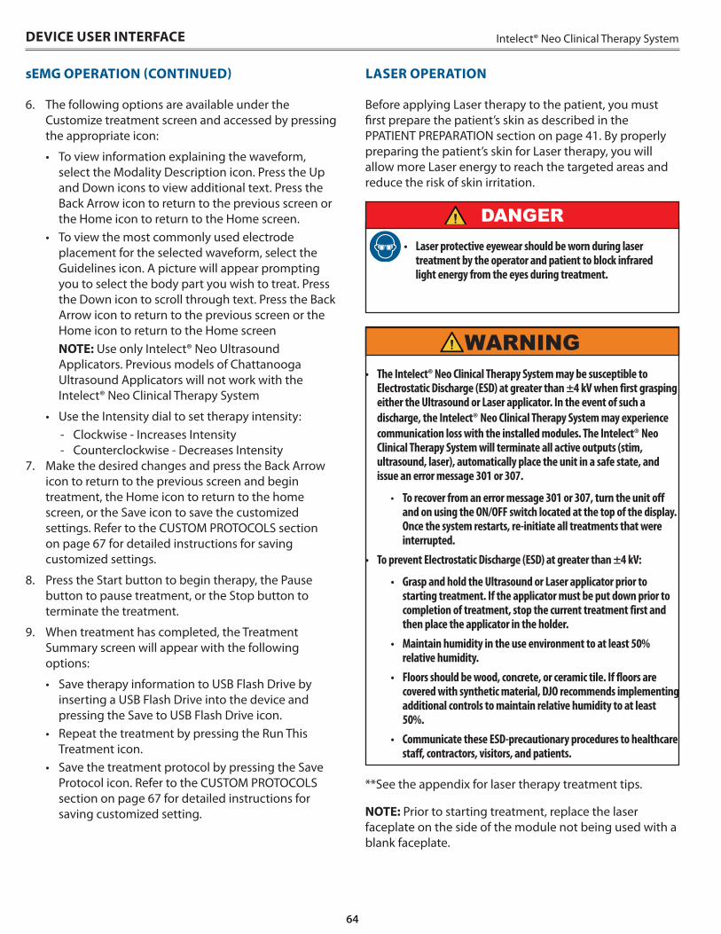
64
Intelect® Neo Clinical Therapy System
Before applying Laser therapy to the patient, you must first prepare the patient’s skin as described in the PPATIENT PREPARATION section on page 41 . By properly preparing the patient’s skin for Laser therapy, you will allow more Laser energy to reach the targeted areas and reduce the risk of skin irritation .
• Laser protective eyewear should be worn during laser treatment by the operator and patient to block infrared light energy from the eyes during treatment.
DANGER
WARNING
**See the appendix for laser therapy treatment tips .
NOTE: Prior to starting treatment, replace the laser faceplate on the side of the module not being used with a blank faceplate .
DEVICE USER INTERFACE
• The Intelect® Neo Clinical Therapy System may be susceptible to Electrostatic Discharge (ESD) at greater than ±4 kV when first grasping either the Ultrasound or Laser applicator. In the event of such a discharge, the Intelect® Neo Clinical Therapy System may experience communication loss with the installed modules. The Intelect® Neo Clinical Therapy System will terminate all active outputs (stim, ultrasound, laser), automatically place the unit in a safe state, and issue an error message 301 or 307.
• To recover from an error message 301 or 307, turn the unit off and on using the ON/OFF switch located at the top of the display. Once the system restarts, re-initiate all treatments that were interrupted.
• To prevent Electrostatic Discharge (ESD) at greater than ±4 kV:
• Grasp and hold the Ultrasound or Laser applicator prior to starting treatment. If the applicator must be put down prior to completion of treatment, stop the current treatment first and then place the applicator in the holder.
• Maintain humidity in the use environment to at least 50% relative humidity.
• Floors should be wood, concrete, or ceramic tile. If floors are covered with synthetic material, DJO recommends implementing additional controls to maintain relative humidity to at least 50%.
• Communicate these ESD-precautionary procedures to healthcare staff, contractors, visitors, and patients.
6 . The following options are available under the Customize treatment screen and accessed by pressing the appropriate icon:
• To view information explaining the waveform, select the Modality Description icon . Press the Up and Down icons to view additional text . Press the Back Arrow icon to return to the previous screen or the Home icon to return to the Home screen .
• To view the most commonly used electrode placement for the selected waveform, select the Guidelines icon . A picture will appear prompting you to select the body part you wish to treat . Press the Down icon to scroll through text . Press the Back Arrow icon to return to the previous screen or the Home icon to return to the Home screen NOTE: Use only Intelect® Neo Ultrasound Applicators . Previous models of Chattanooga Ultrasound Applicators will not work with the Intelect® Neo Clinical Therapy System
• Use the Intensity dial to set therapy intensity: - Clockwise - Increases Intensity - Counterclockwise - Decreases Intensity
7 . Make the desired changes and press the Back Arrow icon to return to the previous screen and begin treatment, the Home icon to return to the home screen, or the Save icon to save the customized settings . Refer to the CUSTOM PROTOCOLS section on page 67 for detailed instructions for saving customized settings .
8 . Press the Start button to begin therapy, the Pause button to pause treatment, or the Stop button to terminate the treatment .
9 . When treatment has completed, the Treatment Summary screen will appear with the following options:
• Save therapy information to USB Flash Drive by inserting a USB Flash Drive into the device and pressing the Save to USB Flash Drive icon .
• Repeat the treatment by pressing the Run This Treatment icon .
• Save the treatment protocol by pressing the Save Protocol icon . Refer to the CUSTOM PROTOCOLS section on page 67 for detailed instructions for saving customized setting .
sEMG OPERATION (CONTINUED) LASER OPERATION
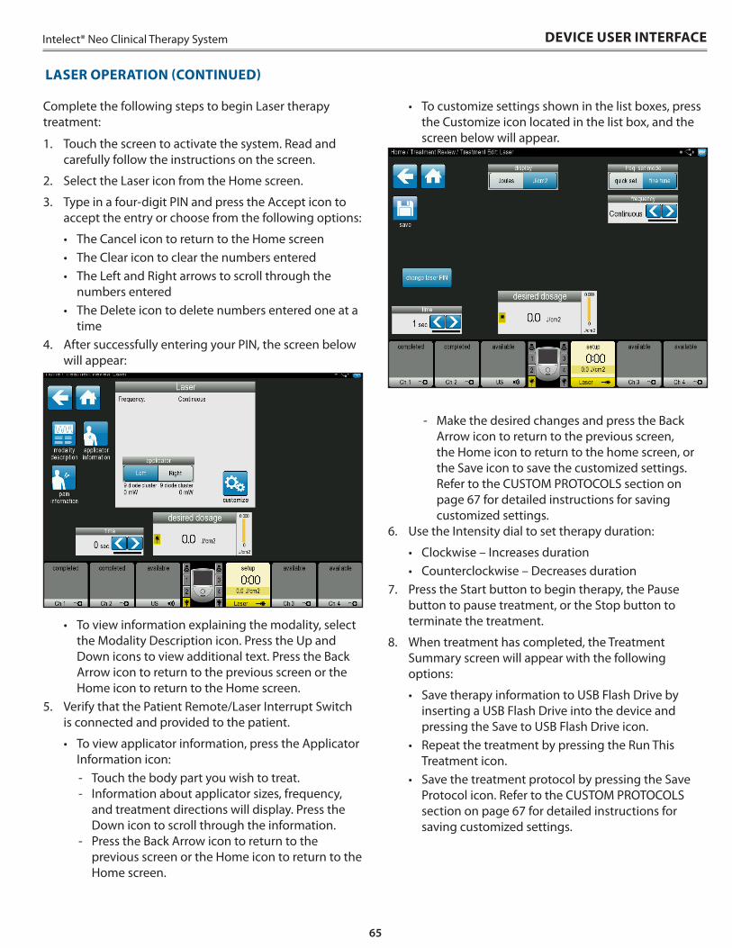
65
Intelect® Neo Clinical Therapy System
• To customize settings shown in the list boxes, press the Customize icon located in the list box, and the screen below will appear .
- Make the desired changes and press the Back Arrow icon to return to the previous screen, the Home icon to return to the home screen, or the Save icon to save the customized settings . Refer to the CUSTOM PROTOCOLS section on page 67 for detailed instructions for saving customized settings .
6 . Use the Intensity dial to set therapy duration:
• Clockwise – Increases duration• Counterclockwise – Decreases duration
7 . Press the Start button to begin therapy, the Pause button to pause treatment, or the Stop button to terminate the treatment .
8 . When treatment has completed, the Treatment Summary screen will appear with the following options:
• Save therapy information to USB Flash Drive by inserting a USB Flash Drive into the device and pressing the Save to USB Flash Drive icon .
• Repeat the treatment by pressing the Run This Treatment icon .
• Save the treatment protocol by pressing the Save Protocol icon . Refer to the CUSTOM PROTOCOLS section on page 67 for detailed instructions for saving customized settings .
Complete the following steps to begin Laser therapy treatment:
1 . Touch the screen to activate the system . Read and carefully follow the instructions on the screen .
2 . Select the Laser icon from the Home screen .
3 . Type in a four-digit PIN and press the Accept icon to accept the entry or choose from the following options:
• The Cancel icon to return to the Home screen• The Clear icon to clear the numbers entered• The Left and Right arrows to scroll through the
numbers entered• The Delete icon to delete numbers entered one at a
time4 . After successfully entering your PIN, the screen below
will appear:
• To view information explaining the modality, select the Modality Description icon . Press the Up and Down icons to view additional text . Press the Back Arrow icon to return to the previous screen or the Home icon to return to the Home screen .
5 . Verify that the Patient Remote/Laser Interrupt Switch is connected and provided to the patient .
• To view applicator information, press the Applicator Information icon:
- Touch the body part you wish to treat . - Information about applicator sizes, frequency,
and treatment directions will display . Press the Down icon to scroll through the information .
- Press the Back Arrow icon to return to the previous screen or the Home icon to return to the Home screen .
LASER OPERATION (CONTINUED)
DEVICE USER INTERFACE
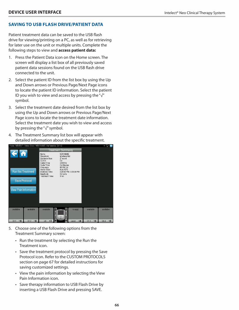
66
Intelect® Neo Clinical Therapy System
Patient treatment data can be saved to the USB flash drive for viewing/printing on a PC, as well as for retrieving for later use on the unit or multiple units . Complete the following steps to view and access patient data:
1 . Press the Patient Data icon on the Home screen . The screen will display a list box of all previously saved patient data sessions found on the USB flash drive connected to the unit .
2 . Select the patient ID from the list box by using the Up and Down arrows or Previous Page/Next Page icons to locate the patient ID information . Select the patient ID you wish to view and access by pressing the “√” symbol .
3 . Select the treatment date desired from the list box by using the Up and Down arrows or Previous Page/Next Page icons to locate the treatment date information . Select the treatment date you wish to view and access by pressing the “√” symbol .
4 . The Treatment Summary list box will appear with detailed information about the specific treatment .
5 . Choose one of the following options from the Treatment Summary screen:
• Run the treatment by selecting the Run the Treatment icon .
• Save the treatment protocol by pressing the Save Protocol icon . Refer to the CUSTOM PROTOCOLS section on page 67 for detailed instructions for saving customized settings .
• View the pain information by selecting the View Pain Information icon .
• Save therapy information to USB Flash Drive by inserting a USB Flash Drive and pressing SAVE .
DEVICE USER INTERFACE
SAVING TO USB FLASH DRIVE/PATIENT DATA
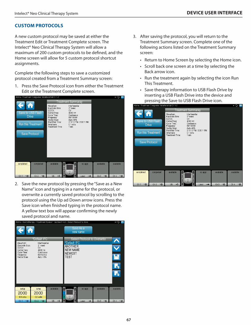
67
Intelect® Neo Clinical Therapy System DEVICE USER INTERFACE
A new custom protocol may be saved at either the Treatment Edit or Treatment Complete screen . The Intelect® Neo Clinical Therapy System will allow a maximum of 200 custom protocols to be defined, and the Home screen will allow for 5 custom protocol shortcut assignments .
Complete the following steps to save a customized protocol created from a Treatment Summary screen:
1 . Press the Save Protocol icon from either the Treatment Edit or the Treatment Complete screen .
2 . Save the new protocol by pressing the “Save as a New Name” icon and typing in a name for the protocol, or overwrite a currently saved protocol by scrolling to the protocol using the Up ad Down arrow icons . Press the Save icon when finished typing in the protocol name . A yellow text box will appear confirming the newly saved protocol and name .
3 . After saving the protocol, you will return to the Treatment Summary screen . Complete one of the following actions listed on the Treatment Summary screen:
• Return to Home Screen by selecting the Home icon . • Scroll back one screen at a time by selecting the
Back arrow icon .• Run the treatment again by selecting the icon Run
This Treatment .• Save therapy information to USB Flash Drive by
inserting a USB Flash Drive into the device and pressing the Save to USB Flash Drive icon .
CUSTOM PROTOCOLS
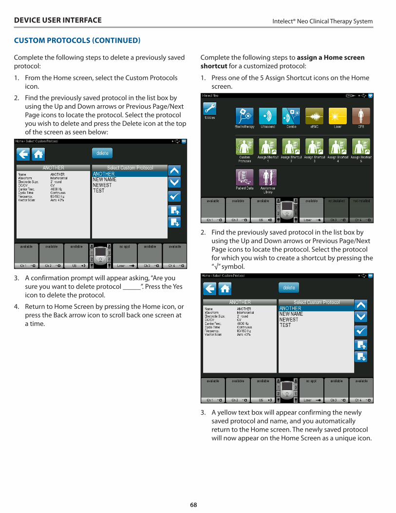
68
Intelect® Neo Clinical Therapy System
Complete the following steps to delete a previously saved protocol:
1 . From the Home screen, select the Custom Protocols icon .
2 . Find the previously saved protocol in the list box by using the Up and Down arrows or Previous Page/Next Page icons to locate the protocol . Select the protocol you wish to delete and press the Delete icon at the top of the screen as seen below:
3 . A confirmation prompt will appear asking, “Are you sure you want to delete protocol _____” . Press the Yes icon to delete the protocol .
4 . Return to Home Screen by pressing the Home icon, or press the Back arrow icon to scroll back one screen at a time .
Complete the following steps to assign a Home screen shortcut for a customized protocol:
1 . Press one of the 5 Assign Shortcut icons on the Home screen .
2 . Find the previously saved protocol in the list box by using the Up and Down arrows or Previous Page/Next Page icons to locate the protocol . Select the protocol for which you wish to create a shortcut by pressing the “√” symbol .
3 . A yellow text box will appear confirming the newly saved protocol and name, and you automatically return to the Home screen . The newly saved protocol will now appear on the Home Screen as a unique icon .
DEVICE USER INTERFACE
CUSTOM PROTOCOLS (CONTINUED)
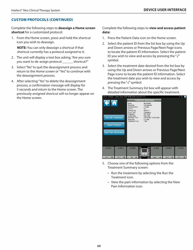
69
Intelect® Neo Clinical Therapy System
CUSTOM PROTOCOLS (CONTINUED)
DEVICE USER INTERFACE
Complete the following steps to deassign a Home screen shortcut for a customized protocol:
1 . From the Home screen, press and hold the shortcut icon you wish to deassign .
NOTE: You can only deassign a shortcut if that shortcut currently has a protocol assigned to it .
2 . The unit will display a text box asking, “Are you sure you want to de-assign protocol ______ shortcut?”
3 . Select “No” to quit the deassignment process and return to the Home screen or “Yes” to continue with the deassignment process .
4 . After selecting “Yes” to delete the deassignment process, a confirmation message will display for 5 seconds and return to the Home screen . The previously assigned shortcut will no longer appear on the Home screen .
Complete the following steps to view and access patient data:
1 . Press the Patient Data icon on the Home screen .
2 . Select the patient ID from the list box by using the Up and Down arrows or Previous Page/Next Page icons to locate the patient ID information . Select the patient ID you wish to view and access by pressing the “√” symbol .
3 . Select the treatment date desired from the list box by using the Up and Down arrows or Previous Page/Next Page icons to locate the patient ID information . Select the treatment date you wish to view and access by pressing the “√” symbol .
4 . The Treatment Summary list box will appear with detailed information about the specific treatment .
5 . Choose one of the following options from the Treatment Summary screen:
• Run the treatment by selecting the Run the Treatment icon .
• View the pain information by selecting the View Pain Information icon .
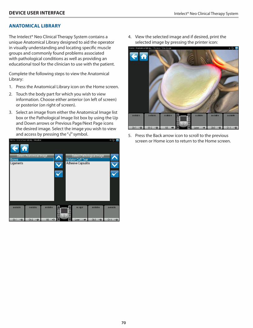
70
Intelect® Neo Clinical Therapy SystemDEVICE USER INTERFACE
ANATOMICAL LIBRARY
The Intelect® Neo Clinical Therapy System contains a unique Anatomical Library designed to aid the operator in visually understanding and locating specific muscle groups and commonly found problems associated with pathological conditions as well as providing an educational tool for the clinician to use with the patient .
Complete the following steps to view the Anatomical Library:
1 . Press the Anatomical Library icon on the Home screen .
2 . Touch the body part for which you wish to view information . Choose either anterior (on left of screen) or posterior (on right of screen) .
3 . Select an image from either the Anatomical Image list box or the Pathological Image list box by using the Up and Down arrows or Previous Page/Next Page icons the desired image . Select the image you wish to view and access by pressing the “√” symbol .
4 . View the selected image and if desired, print the selected image by pressing the printer icon:
5 . Press the Back arrow icon to scroll to the previous screen or Home icon to return to the Home screen .
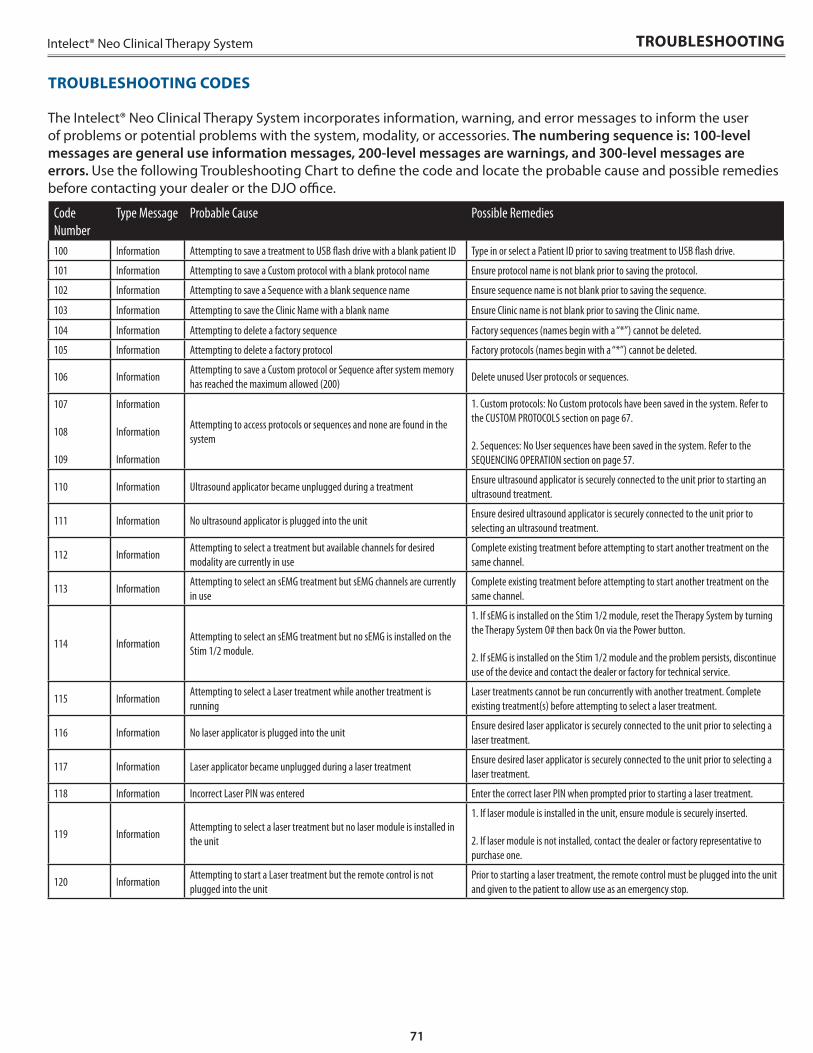
71
Intelect® Neo Clinical Therapy System
Code Number
Type Message Probable Cause Possible Remedies
100 Information Attempting to save a treatment to USB flash drive with a blank patient ID Type in or select a Patient ID prior to saving treatment to USB flash drive.
101 Information Attempting to save a Custom protocol with a blank protocol name Ensure protocol name is not blank prior to saving the protocol.
102 Information Attempting to save a Sequence with a blank sequence name Ensure sequence name is not blank prior to saving the sequence.
103 Information Attempting to save the Clinic Name with a blank name Ensure Clinic name is not blank prior to saving the Clinic name.
104 Information Attempting to delete a factory sequence Factory sequences (names begin with a “*”) cannot be deleted.
105 Information Attempting to delete a factory protocol Factory protocols (names begin with a “*”) cannot be deleted.
106 InformationAttempting to save a Custom protocol or Sequence after system memory has reached the maximum allowed (200)
Delete unused User protocols or sequences.
107
108
109
Information
Information
Information
Attempting to access protocols or sequences and none are found in the system
1. Custom protocols: No Custom protocols have been saved in the system. Refer to the CUSTOM PROTOCOLS section on page 67.
2. Sequences: No User sequences have been saved in the system. Refer to the SEQUENCING OPERATION section on page 57.
110 Information Ultrasound applicator became unplugged during a treatmentEnsure ultrasound applicator is securely connected to the unit prior to starting an ultrasound treatment.
111 Information No ultrasound applicator is plugged into the unitEnsure desired ultrasound applicator is securely connected to the unit prior to selecting an ultrasound treatment.
112 InformationAttempting to select a treatment but available channels for desired modality are currently in use
Complete existing treatment before attempting to start another treatment on the same channel.
113 InformationAttempting to select an sEMG treatment but sEMG channels are currently in use
Complete existing treatment before attempting to start another treatment on the same channel.
114 InformationAttempting to select an sEMG treatment but no sEMG is installed on the Stim 1/2 module.
1. If sEMG is installed on the Stim 1/2 module, reset the Therapy System by turning the Therapy System O# then back On via the Power button.
2. If sEMG is installed on the Stim 1/2 module and the problem persists, discontinue use of the device and contact the dealer or factory for technical service.
115 InformationAttempting to select a Laser treatment while another treatment is running
Laser treatments cannot be run concurrently with another treatment. Complete existing treatment(s) before attempting to select a laser treatment.
116 Information No laser applicator is plugged into the unitEnsure desired laser applicator is securely connected to the unit prior to selecting a laser treatment.
117 Information Laser applicator became unplugged during a laser treatmentEnsure desired laser applicator is securely connected to the unit prior to selecting a laser treatment.
118 Information Incorrect Laser PIN was entered Enter the correct laser PIN when prompted prior to starting a laser treatment.
119 InformationAttempting to select a laser treatment but no laser module is installed in the unit
1. If laser module is installed in the unit, ensure module is securely inserted.
2. If laser module is not installed, contact the dealer or factory representative to purchase one.
120 InformationAttempting to start a Laser treatment but the remote control is not plugged into the unit
Prior to starting a laser treatment, the remote control must be plugged into the unit and given to the patient to allow use as an emergency stop.
The Intelect® Neo Clinical Therapy System incorporates information, warning, and error messages to inform the user of problems or potential problems with the system, modality, or accessories . The numbering sequence is: 100-level messages are general use information messages, 200-level messages are warnings, and 300-level messages are errors. Use the following Troubleshooting Chart to define the code and locate the probable cause and possible remedies before contacting your dealer or the DJO office .
TROUBLESHOOTING
TROUBLESHOOTING CODES
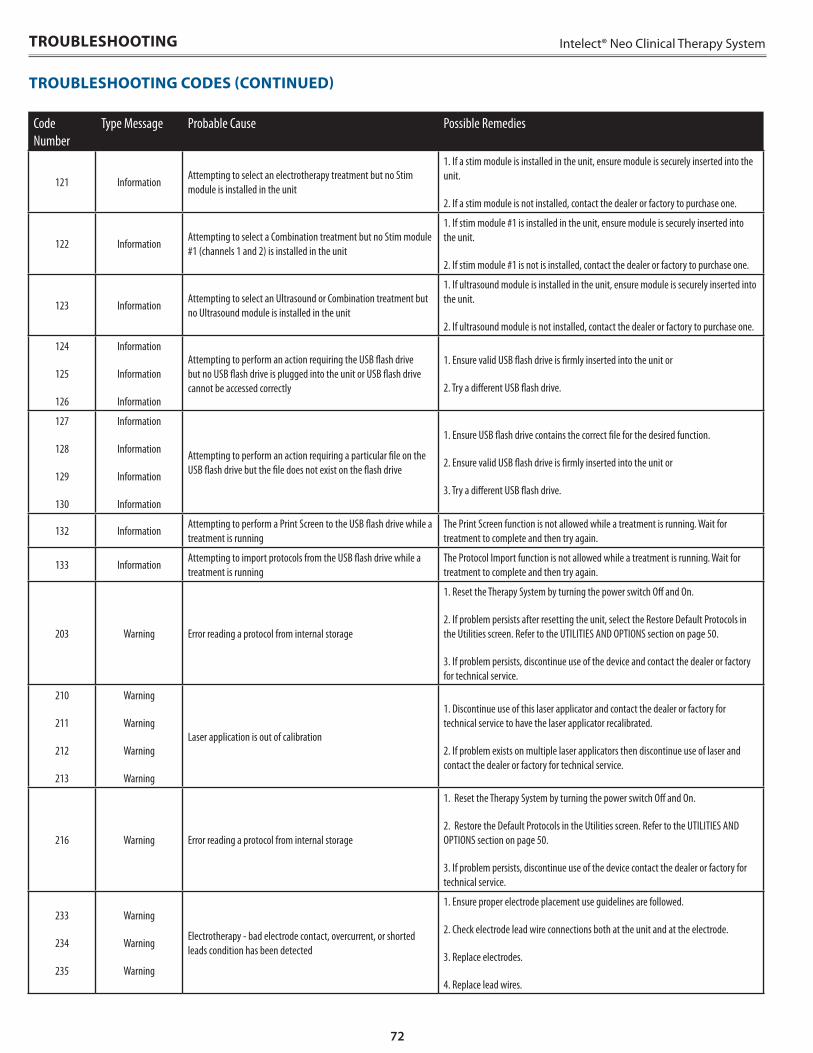
72
Intelect® Neo Clinical Therapy System
Code Number
Type Message Probable Cause Possible Remedies
121 InformationAttempting to select an electrotherapy treatment but no Stim module is installed in the unit
1. If a stim module is installed in the unit, ensure module is securely inserted into the unit.
2. If a stim module is not installed, contact the dealer or factory to purchase one.
122 InformationAttempting to select a Combination treatment but no Stim module #1 (channels 1 and 2) is installed in the unit
1. If stim module #1 is installed in the unit, ensure module is securely inserted into the unit.
2. If stim module #1 is not is installed, contact the dealer or factory to purchase one.
123 InformationAttempting to select an Ultrasound or Combination treatment but no Ultrasound module is installed in the unit
1. If ultrasound module is installed in the unit, ensure module is securely inserted into the unit.
2. If ultrasound module is not installed, contact the dealer or factory to purchase one.
124
125
126
Information
Information
Information
Attempting to perform an action requiring the USB flash drive but no USB flash drive is plugged into the unit or USB flash drive cannot be accessed correctly
1. Ensure valid USB flash drive is firmly inserted into the unit or
2. Try a different USB flash drive.
127
128
129
130
Information
Information
Information
Information
Attempting to perform an action requiring a particular file on the USB flash drive but the file does not exist on the flash drive
1. Ensure USB flash drive contains the correct file for the desired function.
2. Ensure valid USB flash drive is firmly inserted into the unit or
3. Try a different USB flash drive.
132 InformationAttempting to perform a Print Screen to the USB flash drive while a treatment is running
The Print Screen function is not allowed while a treatment is running. Wait for treatment to complete and then try again.
133 InformationAttempting to import protocols from the USB flash drive while a treatment is running
The Protocol Import function is not allowed while a treatment is running. Wait for treatment to complete and then try again.
203 Warning Error reading a protocol from internal storage
1. Reset the Therapy System by turning the power switch Off and On.
2. If problem persists after resetting the unit, select the Restore Default Protocols in the Utilities screen. Refer to the UTILITIES AND OPTIONS section on page 50.
3. If problem persists, discontinue use of the device and contact the dealer or factory for technical service.
210
211
212
213
Warning
Warning
Warning
Warning
Laser application is out of calibration
1. Discontinue use of this laser applicator and contact the dealer or factory for technical service to have the laser applicator recalibrated.
2. If problem exists on multiple laser applicators then discontinue use of laser and contact the dealer or factory for technical service.
216 Warning Error reading a protocol from internal storage
1. Reset the Therapy System by turning the power switch Off and On.
2. Restore the Default Protocols in the Utilities screen. Refer to the UTILITIES AND OPTIONS section on page 50.
3. If problem persists, discontinue use of the device contact the dealer or factory for technical service.
233
234
235
Warning
Warning
Warning
Electrotherapy - bad electrode contact, overcurrent, or shorted leads condition has been detected
1. Ensure proper electrode placement use guidelines are followed.
2. Check electrode lead wire connections both at the unit and at the electrode.
3. Replace electrodes.
4. Replace lead wires.
TROUBLESHOOTING
TROUBLESHOOTING CODES (CONTINUED)
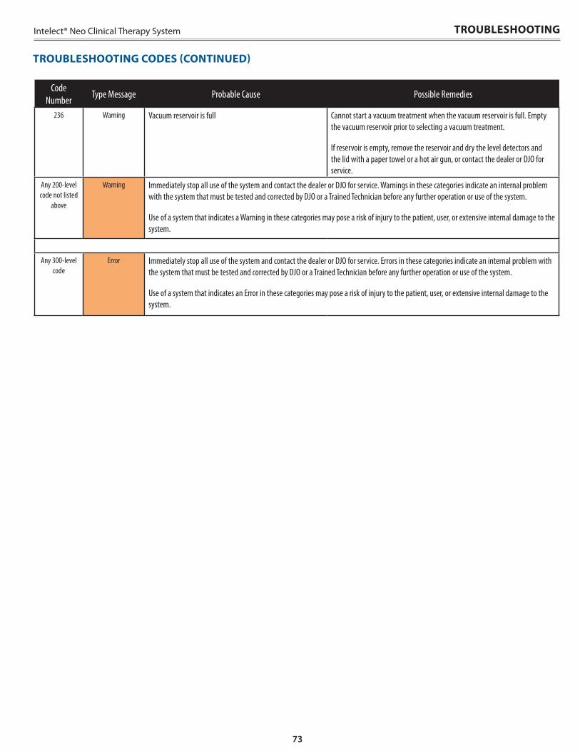
73
Intelect® Neo Clinical Therapy System
Code Number
Type Message Probable Cause Possible Remedies
236 Warning Vacuum reservoir is full Cannot start a vacuum treatment when the vacuum reservoir is full. Empty the vacuum reservoir prior to selecting a vacuum treatment.
If reservoir is empty, remove the reservoir and dry the level detectors and the lid with a paper towel or a hot air gun, or contact the dealer or DJO for service.
Any 200-level code not listed
above
Warning Immediately stop all use of the system and contact the dealer or DJO for service. Warnings in these categories indicate an internal problem with the system that must be tested and corrected by DJO or a Trained Technician before any further operation or use of the system.
Use of a system that indicates a Warning in these categories may pose a risk of injury to the patient, user, or extensive internal damage to the system.
Any 300-level code
Error Immediately stop all use of the system and contact the dealer or DJO for service. Errors in these categories indicate an internal problem with the system that must be tested and corrected by DJO or a Trained Technician before any further operation or use of the system.
Use of a system that indicates an Error in these categories may pose a risk of injury to the patient, user, or extensive internal damage to the system.
TROUBLESHOOTING CODES (CONTINUED)
TROUBLESHOOTING
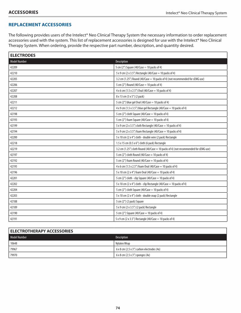
74
Intelect® Neo Clinical Therapy System
The following provides users of the Intelect® Neo Clinical Therapy System the necessary information to order replacement accessories used with the system . This list of replacement accessories is designed for use with the Intelect® Neo Clinical Therapy System . When ordering, provide the respective part number, description, and quantity desired .
ELECTRODES Model Number Description
42209 5 cm (2”) Square (40/Case = 10 packs of 4)
42210 5 x 9 cm (2 x 3.5”) Rectangle (40/Case = 10 packs of 4)
42205 3.2 cm (1.25”) Round (40/Case = 10 packs of 4) (not recommended for sEMG use)
42206 5 cm (2”) Round (40/Case = 10 packs of 4)
42207 4 x 6 cm (1.5 x 2.5”) Oval (40/Case = 10 packs of 4)
42208 8 x 13 cm (3 x 5”) (2 pack)
42211 5 cm (2”) blue gel Oval (40/Case = 10 packs of 4)
42212 4 x 9 cm (1.5 x 3.5”) blue gel Rectangle (40/Case = 10 packs of 4)
42198 5 cm (2”) cloth Square (40/Case = 10 packs of 4)
42193 5 cm (2”) foam Square (40/Case = 10 packs of 4)
42199 5 x 9 cm (2 x 3.5”) cloth Rectangle (40/Case = 10 packs of 4)
42194 5 x 9 cm (2 x 3.5”) foam Rectangle (40/Case = 10 packs of 4)
42200 5 x 10 cm (2 x 4”) cloth - double wire (2 pack) Rectangle
42218 1.5 x 15 cm (0.5 x 6”) cloth (6 pack) Rectangle
42219 3.2 cm (1.25”) cloth Round (40/Case = 10 packs of 4) (not recommended for sEMG use)
42197 5 cm (2”) cloth Round (40/Case = 10 packs of 4)
42192 5 cm (2”) foam Round (40/Case = 10 packs of 4)
42195 4 x 6 cm (1.5 x 2.5”) foam Oval (40/Case = 10 packs of 4)
42196 5 x 10 cm (2 x 4”) foam Oval (40/Case = 10 packs of 4)
42201 5 cm (2”) cloth - clip Square (40/Case = 10 packs of 4)
42202 5 x 10 cm (2 x 4”) cloth - clip Rectangle (40/Case = 10 packs of 4)
42204 5 cm (2”) cloth Square (40/Case = 10 packs of 4)
42203 5 x 10 cm (2 x 4”) cloth - double snap (2 pack) Rectangle
42188 5 cm (2”) (2 pack) Square
42189 5 x 9 cm (2 x 3.5”) (2 pack) Rectangle
42190 5 cm (2”) Square (40/Case = 10 packs of 4)
42191 5 x 9 cm (2 x 3.5”) Rectangle (40/Case = 10 packs of 4)
ELECTROTHERAPY ACCESSORIESModel Number Description
10648 Nylatex Wrap
79967 6 x 8 cm (2.5 x 3”) carbon electrodes (4x)
79970 6 x 8 cm (2.5 x 3”) sponges (4x)
ACCESSORIES
REPLACEMENT ACCESSORIES
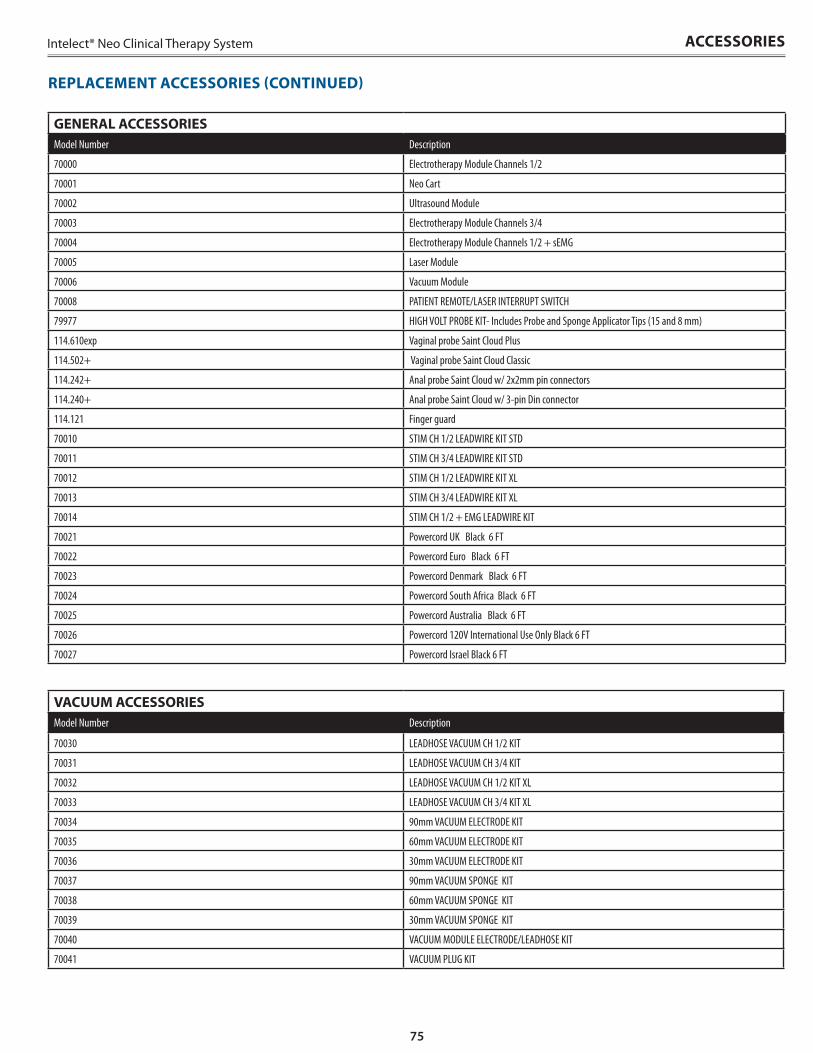
75
Intelect® Neo Clinical Therapy System
REPLACEMENT ACCESSORIES (CONTINUED)
ACCESSORIES
GENERAL ACCESSORIESModel Number Description
70000 Electrotherapy Module Channels 1/2
70001 Neo Cart
70002 Ultrasound Module
70003 Electrotherapy Module Channels 3/4
70004 Electrotherapy Module Channels 1/2 + sEMG
70005 Laser Module
70006 Vacuum Module
70008 PATIENT REMOTE/LASER INTERRUPT SWITCH
79977 HIGH VOLT PROBE KIT- Includes Probe and Sponge Applicator Tips (15 and 8 mm)
114.610exp Vaginal probe Saint Cloud Plus
114.502+ Vaginal probe Saint Cloud Classic
114.242+ Anal probe Saint Cloud w/ 2x2mm pin connectors
114.240+ Anal probe Saint Cloud w/ 3-pin Din connector
114.121 Finger guard
70010 STIM CH 1/2 LEADWIRE KIT STD
70011 STIM CH 3/4 LEADWIRE KIT STD
70012 STIM CH 1/2 LEADWIRE KIT XL
70013 STIM CH 3/4 LEADWIRE KIT XL
70014 STIM CH 1/2 + EMG LEADWIRE KIT
70021 Powercord UK Black 6 FT
70022 Powercord Euro Black 6 FT
70023 Powercord Denmark Black 6 FT
70024 Powercord South Africa Black 6 FT
70025 Powercord Australia Black 6 FT
70026 Powercord 120V International Use Only Black 6 FT
70027 Powercord Israel Black 6 FT
VACUUM ACCESSORIESModel Number Description
70030 LEADHOSE VACUUM CH 1/2 KIT
70031 LEADHOSE VACUUM CH 3/4 KIT
70032 LEADHOSE VACUUM CH 1/2 KIT XL
70033 LEADHOSE VACUUM CH 3/4 KIT XL
70034 90mm VACUUM ELECTRODE KIT
70035 60mm VACUUM ELECTRODE KIT
70036 30mm VACUUM ELECTRODE KIT
70037 90mm VACUUM SPONGE KIT
70038 60mm VACUUM SPONGE KIT
70039 30mm VACUUM SPONGE KIT
70040 VACUUM MODULE ELECTRODE/LEADHOSE KIT
70041 VACUUM PLUG KIT
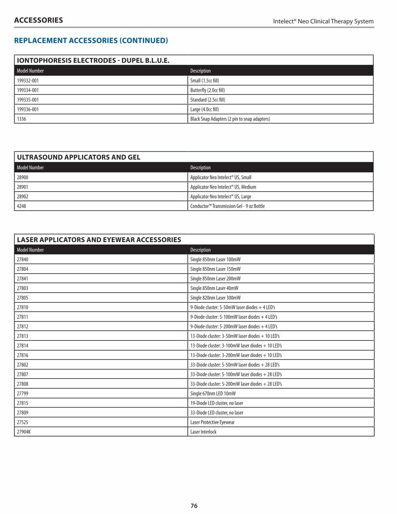
76
Intelect® Neo Clinical Therapy SystemACCESSORIES
REPLACEMENT ACCESSORIES (CONTINUED)
IONTOPHORESIS ELECTRODES - DUPEL B .L .U .E .Model Number Description
199332-001 Small (1.5cc fill)
199334-001 Butterfly (2.0cc fill)
199335-001 Standard (2.5cc fill)
199336-001 Large (4.0cc fill)
1336 Black Snap Adapters (2 pin to snap adapters)
ULTRASOUND APPLICATORS AND GELModel Number Description
28900 Applicator Neo Intelect® US, Small
28901 Applicator Neo Intelect® US, Medium
28902 Applicator Neo Intelect® US, Large
4248 Conductor™ Transmission Gel - 9 oz Bottle
LASER APPLICATORS AND EYEWEAR ACCESSORIESModel Number Description
27840 Single 850nm Laser 100mW
27804 Single 850nm Laser 150mW
27841 Single 850nm Laser 200mW
27803 Single 850nm Laser 40mW
27805 Single 820nm Laser 300mW
27810 9-Diode cluster: 5-50mW laser diodes + 4 LED’s
27811 9-Diode cluster: 5-100mW laser diodes + 4 LED’s
27812 9-Diode cluster: 5-200mW laser diodes + 4 LED’s
27813 13-Diode cluster: 3-50mW laser diodes + 10 LED’s
27814 13-Diode cluster: 3-100mW laser diodes + 10 LED’s
27816 13-Diode cluster: 3-200mW laser diodes + 10 LED’s
27802 33-Diode cluster: 5-50mW laser diodes + 28 LED’s
27807 33-Diode cluster: 5-100mW laser diodes + 28 LED’s
27808 33-Diode cluster: 5-200mW laser diodes + 28 LED’s
27799 Single 670nm LED 10mW
27815 19-Diode LED cluster, no laser
27809 33-Diode LED cluster, no laser
27525 Laser Protective Eyewear
27904K Laser Interlock
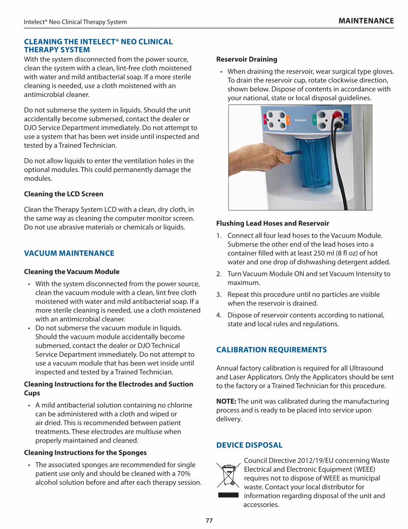
77
Intelect® Neo Clinical Therapy System
With the system disconnected from the power source, clean the system with a clean, lint-free cloth moistened with water and mild antibacterial soap . If a more sterile cleaning is needed, use a cloth moistened with an antimicrobial cleaner .
Do not submerse the system in liquids . Should the unit accidentally become submersed, contact the dealer or DJO Service Department immediately . Do not attempt to use a system that has been wet inside until inspected and tested by a Trained Technician .
Do not allow liquids to enter the ventilation holes in the optional modules . This could permanently damage the modules .
Cleaning the LCD Screen
Clean the Therapy System LCD with a clean, dry cloth, in the same way as cleaning the computer monitor screen . Do not use abrasive materials or chemicals or liquids .
VACUUM MAINTENANCE
Cleaning the Vacuum Module
• With the system disconnected from the power source, clean the vacuum module with a clean, lint free cloth moistened with water and mild antibacterial soap . If a more sterile cleaning is needed, use a cloth moistened with an antimicrobial cleaner .
• Do not submerse the vacuum module in liquids . Should the vacuum module accidentally become submersed, contact the dealer or DJO Technical Service Department immediately . Do not attempt to use a vacuum module that has been wet inside until inspected and tested by a Trained Technician .
Cleaning Instructions for the Electrodes and Suction Cups
• A mild antibacterial solution containing no chlorine can be administered with a cloth and wiped or air dried . This is recommended between patient treatments . These electrodes are multiuse when properly maintained and cleaned .
Cleaning Instructions for the Sponges
• The associated sponges are recommended for single patient use only and should be cleaned with a 70% alcohol solution before and after each therapy session .
MAINTENANCE
CLEANING THE INTELECT® NEO CLINICAL THERAPY SYSTEM
Reservoir Draining
• When draining the reservoir, wear surgical type gloves . To drain the reservoir cup, rotate clockwise direction, shown below . Dispose of contents in accordance with your national, state or local disposal guidelines .
Flushing Lead Hoses and Reservoir
1 . Connect all four lead hoses to the Vacuum Module . Submerse the other end of the lead hoses into a container filled with at least 250 ml (8 fl oz) of hot water and one drop of dishwashing detergent added .
2 . Turn Vacuum Module ON and set Vacuum Intensity to maximum .
3 . Repeat this procedure until no particles are visible when the reservoir is drained .
4 . Dispose of reservoir contents according to national, state and local rules and regulations .
CALIBRATION REQUIREMENTS
Annual factory calibration is required for all Ultrasound and Laser Applicators . Only the Applicators should be sent to the factory or a Trained Technician for this procedure .
NOTE: The unit was calibrated during the manufacturing process and is ready to be placed into service upon delivery .
DEVICE DISPOSAL
Council Directive 2012/19/EU concerning Waste Electrical and Electronic Equipment (WEEE) requires not to dispose of WEEE as municipal waste . Contact your local distributor for information regarding disposal of the unit and
accessories .
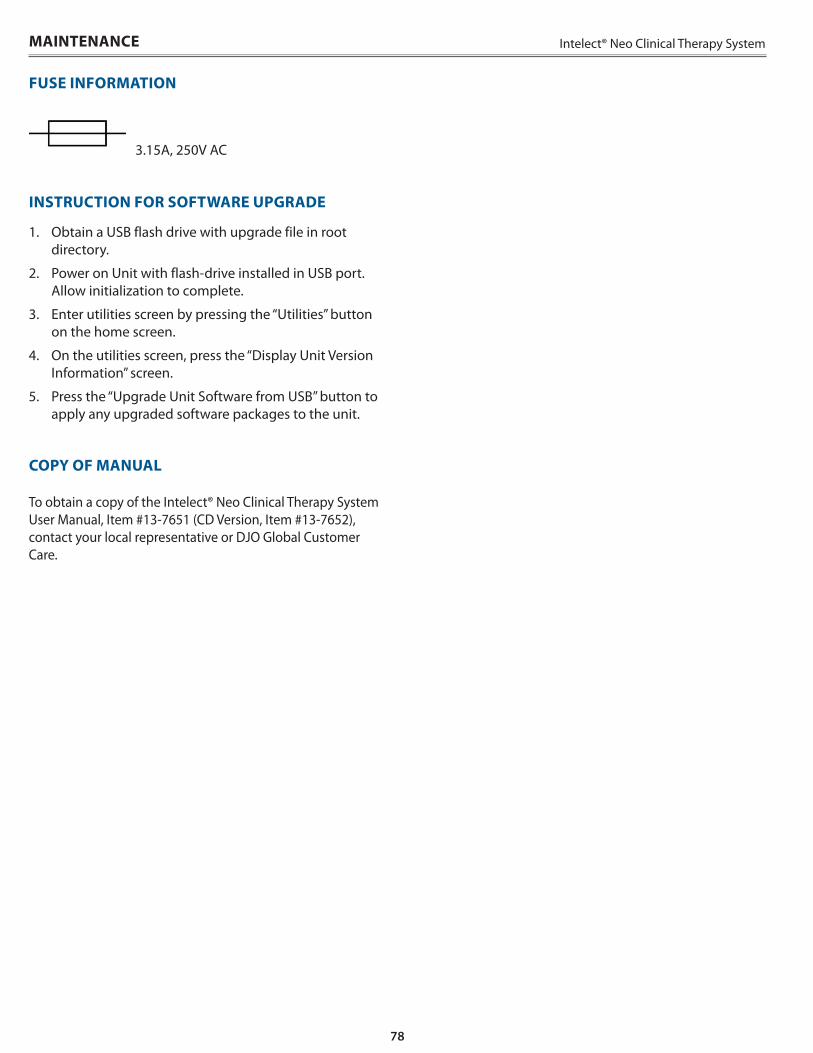
78
Intelect® Neo Clinical Therapy System
3 .15A, 250V AC
INSTRUCTION FOR SOFTWARE UPGRADE
1 . Obtain a USB flash drive with upgrade file in root directory .
2 . Power on Unit with flash-drive installed in USB port . Allow initialization to complete .
3 . Enter utilities screen by pressing the “Utilities” button on the home screen .
4 . On the utilities screen, press the “Display Unit Version Information” screen .
5 . Press the “Upgrade Unit Software from USB” button to apply any upgraded software packages to the unit .
COPY OF MANUAL
To obtain a copy of the Intelect® Neo Clinical Therapy System User Manual, Item #13-7651 (CD Version, Item #13-7652), contact your local representative or DJO Global Customer Care .
MAINTENANCE
FUSE INFORMATION
79
Intelect® Neo Clinical Therapy System SERVICE AND WARRANTY
Service
When the Intelect® Neo Clinical Therapy System or any of the accessory modules require service, contact the selling dealer or DJO Service Department .
All Therapy System and accessory modules returned to the factory for service must include the following:
1 . Written statement containing the following information:
• RA Number – Obtain from DJO• Therapy System or Module Model Number• Therapy System or Module Serial Number• Contact Person with Phone and Fax Numbers• Billing Address (for Out of Warranty Repair)• Shipping Address (Where to Ship Unit after Repair)• Detailed Description of Problem or Symptoms
2 . Copy of original invoice issued at purchase of the Therapy System or Module
3 . Ship the unit to address specified by an authorized Service Technician
Service to these units should be performed only by a service technician certified by the Company .
Ultrasound Applicators require annual calibration, from the date placed in service, by the Factory or a Trained Technician .
Through the purchase of a Service Manual, DJO, LLC has made available circuit diagrams, component part lists, descriptors, or other information which will assist authorized technical personnel to repair those parts of the equipment which are designated by DJO, LLC as repairable .
Expected Life
Expected life of the applicator is 5 years and the control unit is 10 years . Yearly calibration of the device would extend the life of the device for as long as servicing is available by DJO or other factory certified personnel .
WARRANTY REPAIR/OUT OF WARRANTY REPAIR
80
Intelect® Neo Clinical Therapy System
WARRANTY
DJO, LLC (“Company”) warrants that the Intelect® Neo Clinical Therapy System, Channel 1/2 Electrotherapy Module, Channel 1/2 Electrotherapy+EMG Module, Channel 3/4 Electrotherapy Module, Laser Module, Ultrasound Module, and Vacuum Module (“Products”) are free of defects in material and workmanship . This warranty shall remain in effect for two years (24 months) from the date of original consumer purchase . If these Products fail to function during the two year warranty period due to a defect in material or workmanship, at the Company’s option, Company or the selling dealer will repair or replace the respective Product without charge within a period of thirty (30) days from the date on which the Product is returned to the Company or the dealer .
All repairs to the Product must be performed by a service center authorized by the Company . Any modifications or repairs performed by unauthorized centers or groups will void this warranty .
The warranty period for certain accessories is 90 days . Accessories consist of Lead Wires, Patient Remote/Laser Shutoff, and Electrodes .
The warranty period for the Therapy System Cart, Laser Applicators and Ultrasound Applicators is one year (12 months) .
To participate in warranty coverage, this Product’s warranty registration card (included with Product) must be filled out and returned to the Company by the original owner within ten (10) business days of purchase .
This Warranty Does Not Cover:
• Replacement parts or labor furnished by anyone other than the Company, the selling dealer or a Company service technician
• Defects or damage caused by labor furnished by someone other than Company, the selling dealer or a Company service technician
• Any malfunction or failure in the Product caused by product misuse, including, but not limited to, the failure to provide reasonable and required maintenance or any use that is inconsistent with the Product User’s Manual
COMPANY SHALL NOT BE LIABLE IN ANY EVENT FOR INCIDENTAL OR CONSEQUENTIAL DAMAGES .
Some states do not allow the exclusion or limitation of incidental or consequential damages, so the above limitation or exclusion may not apply to you .
To Obtain Service From Company or the selling dealer under this warranty:
1 . A written claim must be made within the warranty period to the Company or the selling dealer . Written claims made to the Company should be sent to:
DJO France SAS Centre Européen de Fret 3 rue de Bethar 64990 Mouguerre, France T: + 33 (0) 5 59 52 86 90 F: + 33 (0) 5 59 52 86 91
and
2 . The Product must be returned to the Company or the selling dealer by the owner .
This warranty gives you specific legal rights and you may also have other rights which vary from location to location .
The Company does not authorize any person or representative to create for it any other obligation or liability in connection with the sale of the Product .
Any representative or agreement not contained in the warranty shall be void and of no effect .
THE FOREGOING WARRANTY IS IN LIEU OF ALL OTHER WARRANTIES, EXPRESSED OR IMPLIED, INCLUDING ANY WARRANTY OF MERCHANTABILITY OR FITNESS FOR A PARTICULAR PURPOSE .
SERVICE AND WARRANTY
81
Intelect® Neo Clinical Therapy System APPENDIX 1
OVERVIEW OF LASER THERAPY
Laser therapy results in energy absorbed into the patient’s tissue from light, triggering biological changes at a cellular level, resulting in the following:
• Topical heating for the temporary increase in local blood circulation
• Temporary relief of minor muscle and joint aches, pains, and stiffness
• Relaxation of muscles and relief of muscle spasm• Temporary relief of minor pain and stiffness associated
with arthritis . The dose and frequency of treatment can be adjusted to produce the desired effect
Low level Laser differs from ordinary light in four ways:
• • It is much more intense .• • It is directional .• • It is monochromatic .• • It is coherent .
Most lasers consist of an active material column with a partially reflective mirror at one end and a fully reflective mirror at the other . The active material can be solid (ruby crystal), liquid, or gas (HeNe, CO2 etc .) . Low level Laser has unique physical properties that no ordinary light has, which makes it so effective in healing compared to other kinds of light . There are more than 100 double-blind positive studies confirming the clinical effect of LLLT (Low Level Laser Therapy) . Over 2500 research reports are published on this topic . A good reference guide for literary documentation on LLLT is a book by Jan Tunér and Lars Hode entitled, Laser Therapy - Clinical Practice and Scientific Background .
There is no exact limit with respect to the penetration of the light . The light gets weaker the further from the surface it penetrates . There is, however, a limit at which the light intensity is so low that no biological effect of the light can be registered . This limit, where the effect ceases, is called “the greatest active depth .” This depth is also contingent on tissue type, pigmentation, and dirt on the skin . For example, fat tissue is more transparent than muscle tissue and more easily penetrable by Laser than muscle tissue as blood hemoglobin is an important absorber of light, and highly vascularized muscle tissue makes Laser penetration more difficult .
NOTE: Some laser applicators may cause a noticeable heat sensation, particularly in hairy areas and on sensitive tissues such as lips .
TREATMENT TIPS
Contact
To obtain the most effective results, the applicator should be in contact with the patient’s skin .
Applicator Position
Due to the characteristics of Laser, the angle at which the light enters the patient’s skin is very important . Therefore, the applicator lens should always be parallel to the treatment area .
Treating Joints
If you are applying Laser therapy to a patient’s joint, it is more effective to apply the Laser energy into the joint by positioning the joint in an open position (e .g ., knee in flexion) . However, do not attempt this method if it is uncomfortable to the patient .
Applicator Selection
If the injury you intend to treat is very small (pinpoint), you should only need to treat the area with a single diode applicator . If the area surrounding the treatment area is sensitive, it is recommended that you apply therapy with a single diode applicator first, then use the cluster applicator for the surrounding area .
Cold and Heat
If you intend to apply cold or heat as an adjunct to Laser therapy, use the following guidelines:
• Use cold before Laser therapy . This slows the flow of red blood cells and reduces the amount of energy removed from the area .
• Use heat after the treatment . This speeds the flow of red blood cells so that more energy can be removed from the area .
82
Intelect® Neo Clinical Therapy SystemAPPENDIX 1
COMMON TERMS
Applicator – Hand held assembly that delivers Laser energy and includes laser head, diode, and related electronics
Collimating – The shape of the Laser beam . It is neither focused or dispersed and resembles a column when applied
Continuous Mode – The output of the Laser is not interrupted during the treatment time
Dosage – Intensity measurement of the Laser energy over the treatment area . It is measured in Joules or Joules/cm2
Energy – Measured in Joules, energy equals the treatment time multiplied by the power . Energy density equals the power output multiplied by the treatment time, and divided by the spot size (cm2) . This gives a more specific measurement of energy delivered
Frequency – Pulsed frequencies are selectable from 8 to 10,000 Hz
Laser Head – The clear lens applicator face contacts the patient’s skin . It consists of laser diodes with or without LED’s or SLD’s (depending on the applicator)
Power – Measured in Watts (W), power wattage is directly proportional to treatment time and penetration of the Laser energy . High-powered diodes will reduce patients’ treatment times and give a higher amount of energy at a deeper depth . Power output can be either continuous or pulsed
Power Density - Ratio of power divided by treatment time
Pulsed Mode - This is the ratio of the “On” time : “Total” time of the cycle, expressed as a percentage . The lower the percentage, the lower temporal average intensity . 100% is continuous Laser . Pulsed Mode is 90% on and 10% off NOTE: Pulsed Mode is also equivalent to Duty Cycle
Spot Size - Area of the LED, SLD, or laser beam when it leaves the face of the lens
Treatment Area - Area of tissue affected by LED, SLD, or laser when wavelength, divergence angles, and depth of penetration are factored . This is the area used to calculate dosage
Treatment Time – Measured in seconds, it is the suggested time per laser point that therapy is given
Wavelength – Wavelength is measured in nanometers (nm) and is the key component in obtaining effective therapy as different wavelengths cause different physiological effects . Superficial skin disorders are most effectively treated at wavelengths 600-700 nm, while deeper muscular or ligament lesions and joint conditions are best treated at higher wavelengths of 700-1000 nm .
83
Intelect® Neo Clinical Therapy System APPENDIX 2
ELECTROMAGNETIC COMPATIBILITY (EMC)
The Intelect® Neo Clinical Therapy System has been tested and found to comply with the electromagnetic compatibility (EMC) limits for medical devices to IEC 60601-1-2 . These limits are designed to provide reasonable protection against harmful interference in a typical medical installation .
The guidelines below are intended to help promote electromagnetic compatibility (EMC) in the identified use environment for the Intelect® Neo Clinical Therapy System .
• Make use of available resources such as EMC professionals and publications and Internet web pages on the subject of medical device EMC;
• Assess the electromagnetic environment of the facility (e .g ., identify radio transmitters in around the facility) and identify areas where critical medical devices are used;
• Manage the electromagnetic environment, RF transmitters and all electrical and electronic equipment, including medical devices, to reduce the risk of medical device electromagnetic interference (EMI) and achieve EMC;
• Coordinate the purchase, installation, service, and management of all electrical and electronic equipment used in the facility to achieve EMC;
• Educate healthcare facility staff, contractors, visitors, and patients about EMC and EMI and how they can recognize medical device EMI and help minimize associated risks;
• Establish and implement written policies and procedures that document the intentions and methods of the healthcare institution for reducing the risk of medical device EMI and achieving EMC;
• Report EMI problems to the US FDA MedWatch program and communicate EMI/EMC experiences to colleagues in open forums such as medical/technical publications and conferences .
More information is contained within a comprehensive guidance document for EMC in healthcare facilities, developed, with FDA participation, by the Association for the Advancement of Medical Instrumentation (AAMI): Technical Information Report (TIR) 18, Guidance on Electromagnetic Compatibility of Medical Devices for Clinical/Biomedical Engineers . AAMI TIR 18-1997 . Arlington, Virginia: Association for the Advancement of Medical Instrumentation; 1997 .
Caution: Medical electrical equipment requires special precautions regarding EMC and must be installed and operated according to these instructions . It is possible that high levels of radiated or conducted radio-frequency electromagnetic interference (EMI) from portable and mobile RF communications equipment or other strong or nearby radio-frequency sources, could result in performance disruption of the ultrasound system . Evidence of disruption may include image degradation or distortion, erratic readings, equipment ceasing to operate, or other incorrect functioning . If this occurs, survey the site of disruption, and take the following actions to eliminate the source(s) .
• Turn equipment in the vicinity off and on to isolate disruptive equipment .
• Relocate or re-orient interfering equipment .• Increase distance between interfering equipment and
your ultrasound system .• Manage use of frequencies close to ultrasound system
frequencies .• Remove devices that are highly susceptible to EMI .• Lower power from internal sources within the facility
control (such as paging systems) .• Label devices susceptible to EMI .• Educate clinical staff to recognize potential EMI-
related problems .• Eliminate or reduce EMI with technical solutions (such
as shielding) .• Restrict use of personal communicators (cell phones,
computers) in areas with devices susceptible to EMI .• Share relevant EMI information with others,
particularly when evaluating new equipment purchases which may generate EMI .
• Purchase medical devices that comply with IEC 60601-1-2 EMC Standards (3V/meter EMI immunity, limit interference level to 0 .0014 V/meter) .
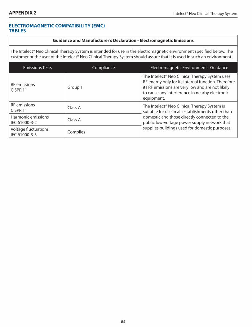
84
Intelect® Neo Clinical Therapy SystemAPPENDIX 2
Guidance and Manufacturer’s Declaration - Electromagnetic Emissions
The Intelect® Neo Clinical Therapy System is intended for use in the electromagnetic environment specified below . The customer or the user of the Intelect® Neo Clinical Therapy System should assure that it is used in such an environment .
Emissions Tests Compliance Electromagnetic Environment - Guidance
RF emissions CISPR 11 Group 1
The Intelect® Neo Clinical Therapy System uses RF energy only for its internal function . Therefore, its RF emissions are very low and are not likely to cause any interference in nearby electronic equipment .
RF emissions CISPR 11 Class A The Intelect® Neo Clinical Therapy System is
suitable for use in all establishments other than domestic and those directly connected to the public low-voltage power supply network that supplies buildings used for domestic purposes .
Harmonic emissions IEC 61000-3-2 Class A
Voltage fluctuations IEC 61000-3-3 Complies
ELECTROMAGNETIC COMPATIBILITY (EMC) TABLES
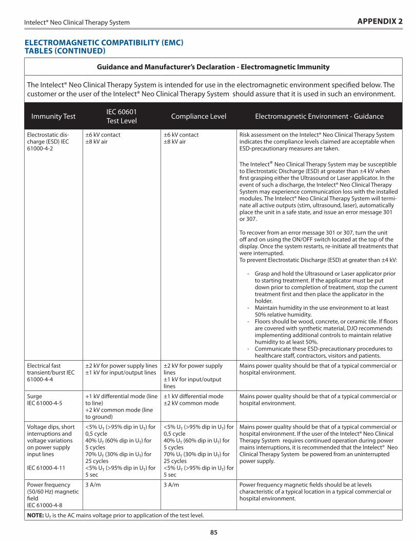
85
Intelect® Neo Clinical Therapy System
Guidance and Manufacturer’s Declaration - Electromagnetic Immunity
The Intelect® Neo Clinical Therapy System is intended for use in the electromagnetic environment specified below . The customer or the user of the Intelect® Neo Clinical Therapy System should assure that it is used in such an environment .
Immunity Test IEC 60601 Test Level Compliance Level Electromagnetic Environment - Guidance
Electrostatic dis-charge (ESD) IEC 61000-4-2
±6 kV contact±8 kV air
±6 kV contact±8 kV air
Risk assessment on the Intelect® Neo Clinical Therapy System indicates the compliance levels claimed are acceptable when ESD-precautionary measures are taken .
The Intelect® Neo Clinical Therapy System may be susceptible to Electrostatic Discharge (ESD) at greater than ±4 kV when first grasping either the Ultrasound or Laser applicator . In the event of such a discharge, the Intelect® Neo Clinical Therapy System may experience communication loss with the installed modules . The Intelect® Neo Clinical Therapy System will termi-nate all active outputs (stim, ultrasound, laser), automatically place the unit in a safe state, and issue an error message 301 or 307 .
To recover from an error message 301 or 307, turn the unit off and on using the ON/OFF switch located at the top of the display . Once the system restarts, re-initiate all treatments that were interrupted .To prevent Electrostatic Discharge (ESD) at greater than ±4 kV:
- Grasp and hold the Ultrasound or Laser applicator prior to starting treatment . If the applicator must be put down prior to completion of treatment, stop the current treatment first and then place the applicator in the holder .
- Maintain humidity in the use environment to at least 50% relative humidity .
- Floors should be wood, concrete, or ceramic tile . If floors are covered with synthetic material, DJO recommends implementing additional controls to maintain relative humidity to at least 50% .
- Communicate these ESD-precautionary procedures to healthcare staff, contractors, visitors and patients .
Electrical fast transient/burst IEC 61000-4-4
±2 kV for power supply lines±1 kV for input/output lines
±2 kV for power supply lines±1 kV for input/output lines
Mains power quality should be that of a typical commercial or hospital environment .
Surge IEC 61000-4-5
+1 kV differential mode (line to line)+2 kV common mode (line to ground)
±1 kV differential mode±2 kV common mode
Mains power quality should be that of a typical commercial or hospital environment .
Voltage dips, short interruptions and voltage variations on power supply input lines
IEC 61000-4-11
<5% UT (>95% dip in UT) for 0,5 cycle40% UT (60% dip in UT) for 5 cycles70% UT (30% dip in UT) for 25 cycles<5% UT (>95% dip in UT) for 5 sec
<5% UT (>95% dip in UT) for 0,5 cycle40% UT (60% dip in UT) for 5 cycles70% UT (30% dip in UT) for 25 cycles<5% UT (>95% dip in UT) for 5 sec
Mains power quality should be that of a typical commercial or hospital environment . If the user of the Intelect® Neo Clinical Therapy System requires continued operation during power mains interruptions, it is recommended that the Intelect® Neo Clinical Therapy System be powered from an uninterrupted power supply .
Power frequency (50/60 Hz) magnetic fieldIEC 61000-4-8
3 A/m 3 A/m Power frequency magnetic fields should be at levels characteristic of a typical location in a typical commercial or hospital environment .
NOTE: UT is the AC mains voltage prior to application of the test level .
ELECTROMAGNETIC COMPATIBILITY (EMC) TABLES (CONTINUED)
APPENDIX 2
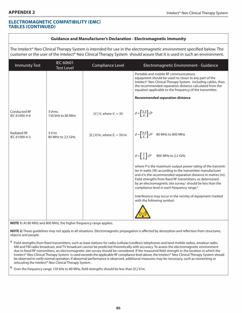
86
Intelect® Neo Clinical Therapy SystemAPPENDIX 2
Guidance and Manufacturer’s Declaration - Electromagnetic Immunity
The Intelect® Neo Clinical Therapy System is intended for use in the electromagnetic environment specified below . The customer or the user of the Intelect® Neo Clinical Therapy System should assure that it is used in such an environment .
Immunity Test IEC 60601 Test Level Compliance Level Electromagnetic Environment - Guidance
Portable and mobile RF communications equipment should be used no closer to any part of the Intelect® Neo Clinical Therapy System, including cables, than the recommended separation distance calculated from the equation applicable to the frequency of the transmitter .
Recommended separation distance
Conducted RFIEC 61000-4-6
3 Vrms150 kHz to 80 MHz [V1] V, where V1 = 3V d = [3,5]√P
V1
Radiated RFIEC 61000-4-3
3 V/m80 MHz to 2,5 GHz [E1] V/m, where E1 = 3V/m d = [3,5]√P 80 MHz to 800 MHz
E1
d = [ 7 ]√P 800 MHz to 2,5 GHz E1
where P is the maximum output power rating of the transmit-ter in watts (W) according to the transmitter manufacturer and d is the recommended separation distance in metres (m) .Field strengths from fixed RF transmitters, as determined by an electromagnetic site survey,a should be less than the compliance level in each frequency range .b
Interference may occur in the vicinity of equipment marked with the following symbol:
NOTE 1: At 80 MHz and 800 MHz, the higher frequency range applies .
NOTE 2: These guidelines may not apply in all situations . Electromagnetic propagation is affected by absorption and reflection from structures, objects and people .
a Field strengths from fixed transmitters, such as base stations for radio (cellular/cordless) telephones and land mobile radios, amateur radio, AM and FM radio broadcast, and TV broadcast cannot be predicted theoretically with accuracy . To assess the electromagnetic environment due to fixed RF transmitters, an electromagnetic site survey should be considered . If the measured field strength in the location in which the Intelect® Neo Clinical Therapy System is used exceeds the applicable RF compliance level above, the Intelect® Neo Clinical Therapy System should be observed to verify normal operation . If abnormal performance is observed, additional measures may be necessary, such as reorienting or relocating the Intelect® Neo Clinical Therapy System .
b Over the frequency range 150 kHz to 80 MHz, field strengths should be less than [V1] V/m .
ELECTROMAGNETIC COMPATIBILITY (EMC) TABLES (CONTINUED)
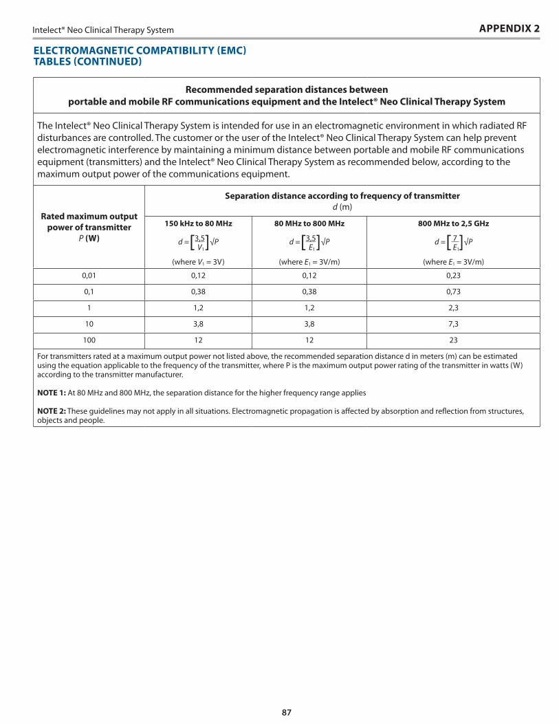
87
Intelect® Neo Clinical Therapy System APPENDIX 2
Recommended separation distances between portable and mobile RF communications equipment and the Intelect® Neo Clinical Therapy System
The Intelect® Neo Clinical Therapy System is intended for use in an electromagnetic environment in which radiated RF disturbances are controlled . The customer or the user of the Intelect® Neo Clinical Therapy System can help prevent electromagnetic interference by maintaining a minimum distance between portable and mobile RF communications equipment (transmitters) and the Intelect® Neo Clinical Therapy System as recommended below, according to the maximum output power of the communications equipment .
Rated maximum output power of transmitter
P (W)
Separation distance according to frequency of transmitterd (m)
150 kHz to 80 MHz
d = [3,5]√P V1
(where V1 = 3V)
80 MHz to 800 MHz
d = [3,5]√P E1
(where E1 = 3V/m)
800 MHz to 2,5 GHz
d = [ 7 ]√P E1
(where E1 = 3V/m)
0,01 0,12 0,12 0,23
0,1 0,38 0,38 0,73
1 1,2 1,2 2,3
10 3,8 3,8 7,3
100 12 12 23
For transmitters rated at a maximum output power not listed above, the recommended separation distance d in meters (m) can be estimated using the equation applicable to the frequency of the transmitter, where P is the maximum output power rating of the transmitter in watts (W) according to the transmitter manufacturer .
NOTE 1: At 80 MHz and 800 MHz, the separation distance for the higher frequency range applies
NOTE 2: These guidelines may not apply in all situations . Electromagnetic propagation is affected by absorption and reflection from structures, objects and people .
ELECTROMAGNETIC COMPATIBILITY (EMC) TABLES (CONTINUED)
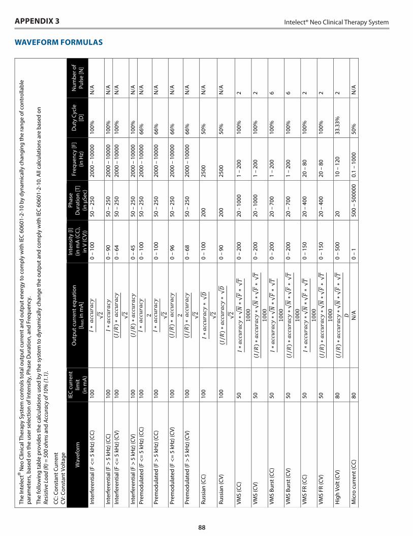
88
Intelect® Neo Clinical Therapy SystemAPPENDIX 3
WAVEFORM FORMULAS
The
Inte
lect
® N
eo C
linic
al T
hera
py S
yste
m c
ontr
ols
tota
l out
put c
urre
nt a
nd o
utpu
t ene
rgy
to c
ompl
y w
ith IE
C 60
601-
2-10
by
dyna
mic
ally
cha
ngin
g th
e ra
nge
of c
ontr
olla
ble
para
met
ers,
bas
ed o
n th
e us
er s
elec
tion
of In
tens
ity, P
hase
Dur
atio
n, a
nd F
requ
ency
.
The
follo
win
g ta
ble
prov
ides
the
calc
ulat
ions
use
d by
the
syst
em to
dyn
amic
ally
cha
nge
the
outp
ut a
nd c
ompl
y w
ith IE
C 60
601-
2-10
. All
calc
ulat
ions
are
bas
ed o
n
Resi
stiv
e Lo
ad (R
) = 5
00 o
hms a
nd A
ccur
acy
of 1
0% (1
.1).
CC: C
onst
ant C
urre
nt
CV: C
onst
ant V
olta
ge
Wav
efor
m
IEC
curr
ent
limit
(in
mA
)
Out
put c
urre
nt e
quat
ion
[I R
MS i
n m
A]
Inte
nsity
[I]
(in m
A (C
C),
in V
(CV)
)
Phas
e D
urat
ion
[T]
(in μ
Sec)
Freq
uenc
y [F
] (in
Hz)
D
uty
Cycl
e [D
] N
umbe
r of
Puls
e [N
]
Inte
rfer
entia
l (F
<= 5
kH
z) (C
C)
100
0
– 10
0 50
– 2
50
2000
– 1
0000
10
0%
N/A
Inte
rfer
entia
l (F
> 5
kHz)
(CC)
10
0
0 –
90
50 –
250
20
00 –
100
00
100%
N
/A
Inte
rfer
entia
l (F
<= 5
kH
z) (C
V)
100
0
– 64
50
– 2
50
2000
– 1
0000
10
0%
N/A
Inte
rfer
entia
l (F
> 5
kHz)
(CV)
10
0
0 –
45
50 –
250
20
00 –
100
00
100%
N
/A
Prem
odul
ated
(F <
= 5
kHz)
(CC)
10
0
0 –
100
50 –
250
20
00 –
100
00
66%
N
/A
Prem
odul
ated
(F >
5 k
Hz)
(CC)
10
0
0 –
100
50 –
250
20
00 –
100
00
66%
N
/A
Prem
odul
ated
(F <
= 5
kHz)
(CV)
10
0
0 –
96
50 –
250
20
00 –
100
00
66%
N
/A
Prem
odul
ated
(F >
5 k
Hz)
(CV)
10
0
0 –
68
50 –
250
20
00 –
100
00
66%
N
/A
Russ
ian
(CC)
10
0
0 –
100
200
2500
50
%
N/A
Russ
ian
(CV)
10
0
0 –
90
200
2500
50
%
N/A
VMS
(CC)
50
0 –
200
20 -
1000
1
– 20
0 10
0%
2
VMS
(CV)
50
0 –
200
20 -
1000
1
– 20
0 10
0%
2
VMS
Burs
t (CC
) 50
0 –
200
20 –
700
1
– 20
0 10
0%
6
VMS
Burs
t (CV
) 50
0 –
200
20 –
700
1
– 20
0 10
0%
6
VMS
FR (C
C)
50
0
– 15
0 20
– 4
00
20 –
80
100%
2
VMS
FR (C
V)
50
0
– 15
0 20
– 4
00
20 –
80
100%
2
Hig
h Vo
lt (C
V)
80
0
– 50
0 20
10
– 1
20
33.3
3%
2
Mic
ro c
urre
nt (C
C)
80
N/A
0
– 1
500
– 50
0000
0.
1 –
1000
50
%
N/A
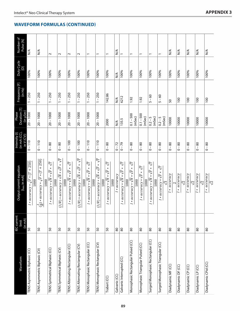
89
Intelect® Neo Clinical Therapy System
WAVEFORM FORMULAS (CONTINUED)
APPENDIX 3
Wav
efor
m
IEC
curr
ent
limit
(in
mA
)
Out
put c
urre
nt e
quat
ion
[I R
MS i
n m
A]
Inte
nsity
[I]
(in m
A (C
C),
in V
(CV)
)
Phas
e D
urat
ion
[T]
(in μ
Sec)
Freq
uenc
y [F
] (in
Hz)
D
uty
Cycl
e [D
] N
umbe
r of
Puls
e [N
]
TEN
S A
sym
met
ric B
ipha
sic
(CC)
50
0 –
110
20 –
100
0 1
– 25
0 10
0%
N/A
TEN
S A
sym
met
ric B
ipha
sic
(CV)
50
0 –
110
20 –
100
0 1
– 25
0 10
0%
N/A
TEN
S Sy
mm
etric
al B
ipha
sic
(CC)
50
0 –
80
20 –
100
0 1
– 25
0 10
0%
2
TEN
S Sy
mm
etric
al B
ipha
sic
(CV)
50
0 –
80
20 –
100
0 1
– 25
0 10
0%
2
TEN
S A
ltern
atin
g Re
ctan
gula
r (CC
) 50
0 –
100
20 –
100
0 1
– 25
0 10
0%
2
TEN
S A
ltern
atin
g Re
ctan
gula
r (CV
) 50
0 –
100
20 –
100
0 1
– 25
0 10
0%
2
TEN
S M
onop
hasi
c Re
ctan
gula
r (CC
) 50
0 –
110
20 –
100
0 1
– 25
0 10
0%
1
TEN
S M
onop
hasi
c Re
ctan
gula
r (CV
) 50
0 –
110
20 –
100
0 1
– 25
0 10
0%
1
Trab
ert (
CC)
50
0
– 80
20
00
142.
86
100%
1
Gal
vani
c (C
C)
80
0
– 72
N
/A
N/A
N
/A
N/A
G
alva
nic
Inte
rrup
ted
(CC)
80
0 –
79
135.
5 62
12
100%
1
Mon
opha
sic
Rect
angu
lar P
ulse
d (C
C)
80
0
– 80
0.
1 –
500
(mSe
c)
1.92
10
0%
1
Mon
opha
sic
Tria
ngul
ar P
ulse
d (C
C)
80
0
– 80
0.
1 –
500
(mSe
c)
1.92
10
0%
1
Surg
ed M
onop
hasi
c Re
ctan
gula
r (CC
) 80
0 –
80
0.2
– 5
(mSe
c)
5 –
60
100%
1
Surg
ed M
onop
hasi
c Tr
iang
ular
(CC)
80
0 –
80
0.2
– 5
(mSe
c)
5 –
60
100%
1
Dia
dyna
mic
MF
(CC)
80
0 –
80
1000
0 50
10
0%
N/A
Dia
dyna
mic
DF
(CC)
80
0 –
80
1000
0 10
0 10
0%
N/A
Dia
dyna
mic
CP
(CC)
80
0 –
80
1000
0 10
0 10
0%
N/A
Dia
dyna
mic
LP
(CC)
80
0 –
80
1000
0 10
0 10
0%
N/A
Dia
dyna
mic
CPi
d (C
C)
80
0
– 80
10
000
100
100%
N
/A
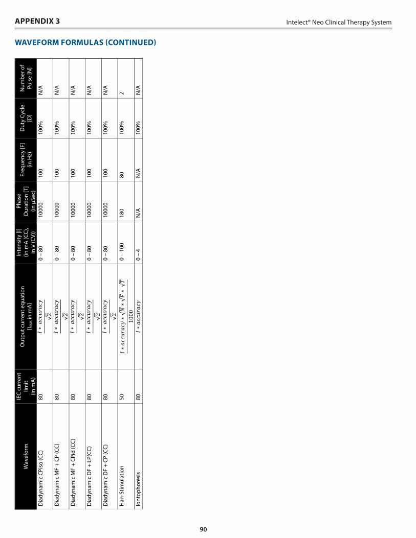
90
Intelect® Neo Clinical Therapy SystemW
avef
orm
IE
C cu
rren
t lim
it
(in m
A)
Out
put c
urre
nt e
quat
ion
[I R
MS i
n m
A]
Inte
nsity
[I]
(in m
A (C
C),
in V
(CV)
)
Phas
e D
urat
ion
[T]
(in μ
Sec)
Freq
uenc
y [F
] (in
Hz)
D
uty
Cycl
e [D
] N
umbe
r of
Puls
e [N
]
Dia
dyna
mic
CPi
so (C
C)
80
0
– 80
10
000
100
100%
N
/A
Dia
dyna
mic
MF
+ CP
(CC)
80
0 –
80
1000
0 10
0 10
0%
N/A
Dia
dyna
mic
MF
+ CP
id (C
C)
80
0
– 80
10
000
100
100%
N
/A
Dia
dyna
mic
DF
+ LP
(CC)
80
0 –
80
1000
0 10
0 10
0%
N/A
Dia
dyna
mic
DF
+ CP
(CC)
80
0 –
80
1000
0 10
0 10
0%
N/A
Han
-Stim
ulat
ion
50
0
– 10
0 18
0 80
10
0%
2
Iont
opho
resi
s 80
0 –
4 N
/A
N/A
10
0%
N/A
WAVEFORM FORMULAS (CONTINUED)
APPENDIX 3


DJO France SAS Centre Européen de Fret 3 rue de Bethar 64990 Mouguerre, France T: + 33 (0) 5 59 52 86 90 F: + 33 (0) 5 59 52 86 91 djoglobal.eu/fr_FR
© 2015 DJO, LLC. All rights reserved.
Intelect® Neo Clinical Therapy System Manual 13-7651 Rev F 06/2015