intel® embedded graphics drivers, efi video driver, and ... · 3.16 enhanced clone mode support...
TRANSCRIPT

Document Number: 274041-029US
Intel® Embedded Graphics Drivers, EFI Video Driver, and Video BIOS v10.3.1User’s Guide
March 2010

Intel® Embedded Graphics Drivers, EFI Video Driver, and Video BIOSUser’s Guide March 2010 2 Document Number: 274041-029US
Legal Lines and DisclaimersINFORMATION IN THIS DOCUMENT IS PROVIDED IN CONNECTION WITH INTEL® PRODUCTS. NO LICENSE, EXPRESS OR IMPLIED, BY ESTOPPEL OR OTHERWISE, TO ANY INTELLECTUAL PROPERTY RIGHTS IS GRANTED BY THIS DOCUMENT. EXCEPT AS PROVIDED IN INTEL’S TERMS AND CONDITIONS OF SALE FOR SUCH PRODUCTS, INTEL ASSUMES NO LIABILITY WHATSOEVER, AND INTEL DISCLAIMS ANY EXPRESS OR IMPLIED WARRANTY, RELATING TO SALE AND/OR USE OF INTEL PRODUCTS INCLUDING LIABILITY OR WARRANTIES RELATING TO FITNESS FOR A PARTICULAR PURPOSE, MERCHANTABILITY, OR INFRINGEMENT OF ANY PATENT, COPYRIGHT OR OTHER INTELLECTUAL PROPERTY RIGHT. Intel products are not intended for use in medical, life saving, life sustaining, critical control or safety systems, or in nuclear facility applications.
Intel may make changes to specifications and product descriptions at any time, without notice. Designers must not rely on the absence or characteristics of any features or instructions marked “reserved” or “undefined.” Intel reserves these for future definition and shall have no responsibility whatsoever for conflicts or incompatibilities arising from future changes to them. The information here is subject to change without notice. Do not finalize a design with this information.
The products described in this document may contain design defects or errors known as errata which may cause the product to deviate from published specifications. Current characterized errata are available on request.
Contact your local Intel sales office or your distributor to obtain the latest specifications and before placing your product order.
Copies of documents which have an ordering number and are referenced in this document, or other Intel literature, may be obtained from:
Intel Corporation
P.O. Box 5937
Denver, CO 80217-9808
or call in North America 1-800-548-4725, Europe 44-0-1793-431-155, France 44-0-1793-421-777, Germany 44-0-1793-421-333, other Countries 708-296-9333 or by visiting Intel’s Web Site.
Any software source code reprinted in this document is furnished under a software license and may only be used or copied in accordance with the terms of that license.
Intel processor numbers are not a measure of performance. Processor numbers differentiate features within each processor family, not across different processor families. See http://www.intel.com/products/processor_number for details.
BunnyPeople, Celeron, Celeron Inside, Centrino, Centrino logo, Core Inside, FlashFile, i960, InstantIP, Intel, Intel logo, Intel386, Intel486, Intel740, IntelDX2, IntelDX4, IntelSX2, Intel Core, Intel Inside, Intel Inside logo, Intel. Leap ahead., Intel. Leap ahead. logo, Intel NetBurst, Intel NetMerge, Intel NetStructure, Intel SingleDriver, Intel SpeedStep, Intel StrataFlash, Intel Viiv, Intel vPro, Intel XScale, Itanium, Itanium Inside, MCS, MMX, Oplus, OverDrive, PDCharm, Pentium, Pentium Inside, skoool, Sound Mark, The Journey Inside, VTune, Xeon, and Xeon Inside are trademarks of Intel Corporation in the U.S. and other countries.
*Other names and brands may be claimed as the property of others.
Copyright © 2010, Intel Corporation. All rights reserved.

Intel® Embedded Graphics Drivers, EFI Video Driver, and Video BIOSMarch 2010 User’s Guide Document Number: 274041-029US 3
Contents
Contents
1.0 Introduction............................................................................................................. 131.1 Purpose ........................................................................................................... 141.2 Intended Audience ............................................................................................ 141.3 Related Documents ........................................................................................... 141.4 Conventions ..................................................................................................... 151.5 New Features for Version 10.3.1.......................................................................... 161.6 Acronyms and Terminology................................................................................. 161.7 Downloading the IEGD and Video BIOS ................................................................ 20
2.0 Architectural Overview ............................................................................................ 212.1 Introduction ..................................................................................................... 21
2.1.1 Display Options...................................................................................... 232.1.1.1 Types of Displays...................................................................... 232.1.1.2 Display Configuration ................................................................ 23
2.2 Features .......................................................................................................... 242.2.1 Chipsets Supported ................................................................................ 242.2.2 OS and API Support................................................................................ 252.2.3 DisplayID Support .................................................................................. 252.2.4 EDID-Less Configuration ......................................................................... 25
2.2.4.1 EDID-Less Panel Type Detection ................................................. 252.2.5 sDVO Devices ........................................................................................ 262.2.6 Rotation................................................................................................ 27
3.0 Platform Configuration Using CED............................................................................ 293.1 Before You Begin............................................................................................... 303.2 Creating a Configuration in CED – Summary Steps................................................. 303.3 Starting the CED ............................................................................................... 313.4 Creating a New Customized DTD ......................................................................... 32
3.4.1 DTD Example Specifications..................................................................... 353.5 Creating a New Configuration.............................................................................. 36
3.5.1 Setting Color Correction .......................................................................... 393.5.1.1 Overlay Color Correction ............................................................ 393.5.1.2 Framebuffer Color Correction Attributes ....................................... 40
3.5.2 Changing Windows CE OS Options ............................................................ 413.5.3 Configuring Ports ................................................................................... 44
3.5.3.1 Changing Port Attribute Settings ................................................. 463.5.3.2 Changing I2C Settings............................................................... 473.5.3.3 Changing Flat Panel Settings ...................................................... 48
3.5.4 Configuring Fastboot............................................................................... 513.5.4.1 Configuring Splash Video ........................................................... 533.5.4.2 How to Select the Video_Offset................................................... 54
3.5.5 Configuring the Video BIOS and EFI.......................................................... 553.6 Creating a New Package..................................................................................... 57
3.6.1 Entering Linux OS Options....................................................................... 603.6.2 Entering Windows OS Options .................................................................. 623.6.3 Generating a VBIOS Package ................................................................... 633.6.4 Entering EFI Options............................................................................... 633.6.5 Using the Generated EFI Configuration ...................................................... 653.6.6 Entering EPOG Feature Options ................................................................ 653.6.7 Using the Generated Embedded Pre-OS Graphics Feature Configuration......... 66
3.7 Generating an Installation .................................................................................. 663.8 Configuring the System BIOS for Use with the IEGD............................................... 66

Contents
Intel® Embedded Graphics Drivers, EFI Video Driver, and Video BIOSUser’s Guide March 2010 4 Document Number: 274041-029US
3.9 System BIOS Settings ........................................................................................673.9.1 GMCH PCI Device Enabling.......................................................................673.9.2 Graphics Mode Select (GMS) ....................................................................673.9.3 AGP (Accelerated Graphics Port) Aperture Size ...........................................68
3.10 VBIOS and Driver Configuration...........................................................................683.11 Configuration Options.........................................................................................713.12 Display Detection and Initialization.......................................................................78
3.12.1 Display Detect Operation .........................................................................783.12.2 Detectable Displays.................................................................................80
3.13 Advanced EDID Configuration..............................................................................803.13.1 Sample Advanced EDID Configurations ......................................................813.13.2 User-Specified DTDs ...............................................................................81
3.14 Using an External PCI Graphics Adapter as the Primary Device.................................823.15 Hybrid Multi-monitor ..........................................................................................843.16 Enhanced Clone Mode Support ............................................................................85
3.16.1 Extended Clone Mode CED Configuration....................................................853.16.2 Sample Clone Mode Configurations............................................................87
3.17 Scaling and Centering Configurations ...................................................................883.17.1 Upscaling for the Chrontel CH7308 LVDS Transmitters .................................883.17.2 Internal LVDS Scaling with EDID Panels .....................................................893.17.3 Centering Primary Display with Scaling Encoders.........................................893.17.4 Enabling Render Scaling on Port Encoders without Hardware Scaling .............893.17.5 Alignment in Clone Mode .........................................................................90
4.0 VBIOS.......................................................................................................................914.1 Overview..........................................................................................................914.2 System Requirements ........................................................................................914.3 Configuring and Building the VBIOS with CED........................................................92
4.3.1 Selecting the Build Folder ........................................................................934.3.2 Configuring the Video BIOS......................................................................93
4.3.2.1 COMMON_TO_PORT...................................................................944.3.2.2 post_display_msg .....................................................................944.3.2.3 OEM Vendor Strings...................................................................944.3.2.4 Default Mode Settings................................................................954.3.2.5 Default Refresh Settings.............................................................954.3.2.6 default_vga_height....................................................................95
4.3.3 Building the VBIOS .................................................................................954.4 VBIOS, Driver Compatibility, and Data Dependencies..............................................994.5 VESA and VGA Video Modes ................................................................................99
5.0 Configuring and Installing Microsoft Windows Drivers ...........................................1035.1 Editing the Microsoft Windows INF File................................................................1035.2 Configuration Information .................................................................................103
5.2.1 Universal INF Configuration....................................................................1035.2.2 INF File Backward Compatibility..............................................................104
5.2.2.1 INF File Backward Compatibility with IEGD Version 4.0.................1045.2.3 Dual Panel Configuration........................................................................1045.2.4 Chipset Dual Display Example ................................................................1055.2.5 Creating Registry Settings for Graphics Driver INF File ...............................1055.2.6 Dynamic Port Driver Configuration ..........................................................107
5.2.6.1 iegd.PortDrvs_xxx ...................................................................1075.2.6.2 SourceDisksFiles .....................................................................1085.2.6.3 PortDrivers Registry Key ..........................................................108
5.2.7 Creating an .sld file for Microsoft Windows XP Embedded Systems...............1095.2.8 Changing Default Display Mode...............................................................109
Intel® Embedded Graphics Drivers, EFI Video Driver, and Video BIOSMarch 2010 User’s Guide Document Number: 274041-029US 5
Contents
5.3 Installing the IEGD on Microsoft Windows ........................................................... 1095.3.1 Silent Installation ................................................................................. 110
5.4 Uninstalling the Current Version of the Driver...................................................... 1125.5 Run-Time Operation ........................................................................................ 1135.6 Viewing and Changing the Driver Configuration from Microsoft Windows ................. 113
6.0 Configuring and Building the IEGD for Microsoft Windows CE* Systems................ 1196.1 Overview ....................................................................................................... 1196.2 Microsoft Windows CE* Installation.................................................................... 119
6.2.1 Prerequisites ....................................................................................... 1206.2.2 Integrating IEGD with Microsoft Windows CE* Platform Builder................... 120
6.2.2.1 Catalog Feature File ................................................................ 1226.2.3 Microsoft Windows CE* 6.0 Installation ................................................... 122
6.2.3.1 Prerequisites .......................................................................... 1226.2.3.2 CED Requirements .................................................................. 1226.2.3.3 Platform Builder Requirements.................................................. 122
6.2.3.3.1 Platform.reg Changes ............................................ 1236.2.3.3.2 Platform.bib Changes............................................. 123
6.2.4 Integrating IEGD DirectX DirectShow Codecs for Intel® System Controller Hub US15W .......................................................................... 1246.2.4.1 IEGD DirectShow Codecs Overview ........................................... 1246.2.4.2 Installing IEGD DirectShow Codecs............................................ 124
6.3 Microsoft Windows CE* Configuration................................................................. 1256.3.1 Basic Driver Configuration ..................................................................... 125
6.3.1.1 Graphics Memory Configuration ................................................ 1266.3.1.2 Defining Graphics Memory Size................................................. 1276.3.1.3 Framebuffer and Video Surface Size .......................................... 1296.3.1.4 Video Surface Allocation Rule ................................................... 1296.3.1.5 System to Video Stretch Blit..................................................... 1306.3.1.6 iegd.reg File Backward Compatibility ......................................... 130
6.3.2 Configuration Sets................................................................................ 1306.3.3 General Configuration ........................................................................... 130
6.3.3.1 PortOrder Information ............................................................. 1336.3.3.2 Vertical Extended Mode ........................................................... 134
6.3.4 Per Port Platform Customization ............................................................. 1346.3.4.1 Per Port Customization — General Port Configuration................... 1346.3.4.2 Per Port Customization — Custom DTD Timings .......................... 1356.3.4.3 Per Port Customization — Custom Flat Panel Controls .................. 1366.3.4.4 Per Port Customization — Attribute Initialization.......................... 136
6.3.5 Miscellaneous Configuration Options ....................................................... 1376.3.5.1 Text Anti-Aliasing ................................................................... 137
6.3.6 Direct3D* Mobile Support...................................................................... 1376.3.7 Sample iegd.reg File ............................................................................. 138
7.0 Installing and Configuring Linux* OS Drivers......................................................... 1497.1 Overview ....................................................................................................... 1497.2 Prerequisites................................................................................................... 149
7.2.1 Supported Hardware............................................................................. 1507.3 Installation..................................................................................................... 151
7.3.1 Linux Installer Overview........................................................................ 1517.3.2 Installing Fedora 7 (not supported with Intel® US15W) ............................. 1527.3.3 Installing Fedora 10.............................................................................. 1547.3.4 Installing Wind River Linux Platform for Infotainment ................................ 156
7.3.4.1 Installing the IEGD Driver ........................................................ 1577.3.4.2 Installing Helix ....................................................................... 1587.3.4.3 Installing Codecs .................................................................... 158

Contents
Intel® Embedded Graphics Drivers, EFI Video Driver, and Video BIOSUser’s Guide March 2010 6 Document Number: 274041-029US
7.3.5 Installing Red Hat Embedded (for Intel® US15W/US15WP/WPT only)...........1587.3.5.1 Creating the IEGD Kernel Module...............................................1587.3.5.2 Installing IEGD on a Red Hat Embedded System..........................1597.3.5.3 Installing Codecs.....................................................................161
7.3.6 Installing Ubuntu IEGD Driver and Codec (for Intel® US15W/US15WP/WPT only) ....................................................1617.3.6.1 Installing the Ubuntu OS ..........................................................1627.3.6.2 Installing the IEGD Driver for Ubuntu.........................................1677.3.6.3 Installing the Helix DBus Server ................................................169
7.3.7 Installing Moblin 2.1 IVI (for Intel® US15W only) ......................................1707.3.7.1 Install the Pre-integrated Moblin Image......................................1707.3.7.2 Manually Installing IEGD ..........................................................1707.3.7.3 Preparing for the Intel Embedded Graphics Driver Installation .......1707.3.7.4 Installing the Intel Embedded Graphics Driver (IEGD)
for Moblin 2.1 .........................................................................1717.3.7.5 Known Issues .........................................................................173
7.4 IKM Patch Instructions .....................................................................................1737.4.1 Finding and Installing the Kernel Source (Headers) ...................................1737.4.2 Installing IKM with Fedora .....................................................................1737.4.3 Using the IEGD Kernel Module ................................................................1747.4.4 Linux Installer IKM Validation .................................................................175
7.4.4.1 AGP Test................................................................................1757.4.4.2 DRM Test ...............................................................................1757.4.4.3 Kernel Checker .......................................................................175
7.5 Uninstalling the IKM.........................................................................................1797.6 Configuring Linux*...........................................................................................179
7.6.1 Configuration Overview .........................................................................1797.6.2 Linux* OS Configuration Using CED.........................................................1807.6.3 Editing the Linux* OS Configuration File Directly .......................................1807.6.4 The Linux* OS Configuration File ............................................................180
7.6.4.1 Device Section ........................................................................1837.6.4.2 Screen Section........................................................................1857.6.4.3 Monitor Section.......................................................................1867.6.4.4 ServerLayout Section...............................................................1867.6.4.5 ServerFlags Section .................................................................186
7.6.5 Xorg* Configuration Options...................................................................1877.6.6 Sample Dual Independent Head (DIH) Configuration .................................1907.6.7 Video Memory Management ...................................................................1927.6.8 Configuring Accelerated Video Decode for IEGD and Intel®
System Controller Hub US15W ...............................................................1927.6.8.1 Hardware Video Acceleration Overview.......................................1927.6.8.2 IEGD Driver............................................................................1937.6.8.3 Installing the VA Library (version 0.29) ......................................1937.6.8.4 Installing the IEGD Video Acceleration Driver ..............................1937.6.8.5 Installing Helix Framework .......................................................1947.6.8.6 Installing Intel® Media Codec....................................................1947.6.8.7 Playing Video..........................................................................1947.6.8.8 Troubleshooting ......................................................................195
7.6.9 Graphics Port Initialization .....................................................................1957.6.10 OpenGL Support ...................................................................................196
7.6.10.1 OpenGL Installation .................................................................1977.6.10.2 OpenGL Use Considerations ......................................................1997.6.10.3 OpenGL ES.............................................................................199
7.6.11 Sample Advanced EDID Configurations for Linux* OS ................................1997.6.12 AGP GART Errors ..................................................................................200

Intel® Embedded Graphics Drivers, EFI Video Driver, and Video BIOSMarch 2010 User’s Guide Document Number: 274041-029US 7
Contents
7.7 Runtime Configuration GUI ............................................................................... 2007.7.1 iegdgui Setup ...................................................................................... 2017.7.2 Using the iegdgui Runtime Configuration Utility ........................................ 201
A Example INF File.................................................................................................... 207
B Port Driver Attributes ............................................................................................ 213B.1 Standard Port Driver Attributes ......................................................................... 213B.2 Port Driver Attributes....................................................................................... 215
B.2.1 Internal LVDS Port Driver Attributes (Mobile chipsets only) ........................ 215B.2.2 CRT (Analog) Port Driver Attributes ........................................................ 216B.2.3 HDMI Port Driver Attributes ................................................................... 216
B.2.3.1 Audio .................................................................................... 216B.2.3.2 SDVO-HDMI (CH7315) ............................................................ 217B.2.3.3 Internal HDMI ........................................................................ 217B.2.3.4 HDCP .................................................................................... 217
B.2.4 Internal TV Out Port Driver Attributes (Mobile chipsets only) ...................... 217B.2.5 Chrontel CH7307 Port Driver Attributes ................................................... 218B.2.6 Chrontel CH7308 Port Driver Attributes ................................................... 218B.2.7 Chrontel CH7315/CH7319/CH7320 Port Driver Attributes........................... 219B.2.8 Chrontel CH7317 Port Driver Attributes ................................................... 219B.2.9 Chrontel CH7022 Port Driver Attributes ................................................... 220B.2.10 Silicon Image SiI 1362/SiI 1364 Port Driver DVI Attributes ........................ 221
B.3 Chipset and Port Driver-specific Installation Information ....................................... 222B.3.1 Default Search Order ............................................................................ 222B.3.2 Default GPIO Pin Pair Assignments.......................................................... 222B.3.3 Default I2C Device Address Byte Assignment ........................................... 223
C Intel® 5F Extended Interface Functions................................................................. 225C.1 BIOS Extended Interface Functions.................................................................... 226
C.1.1 5F01h – Get Video BIOS Information ...................................................... 226C.1.2 5F05h – Refresh Rate ........................................................................... 227
C.1.2.1 5F05h, 00h – Set Refresh Rate ................................................. 227C.1.2.2 5F05h, 01h – Get Refresh Rate................................................. 228
C.1.3 5F10h – Get Display Memory Information ................................................ 229C.1.4 5F1Ch – BIOS Pipe Access ..................................................................... 229
C.1.4.1 5F1Ch, 00h – Set BIOS Pipe Access........................................... 229C.1.4.2 5F1Ch, 01h – Get BIOS Pipe Access .......................................... 229
C.1.5 5F29h – Get Mode Information............................................................... 230C.1.6 5F61h – Local Flat Panel Support Function ............................................... 230
C.1.6.1 5F61h, 05h – Get Configuration ID............................................ 230C.1.7 5F68h – System BIOS Callback .............................................................. 231
C.2 Hooks for the System BIOS .............................................................................. 231C.2.1 5F31h – POST Completion Notification Hook............................................. 231C.2.2 5F33h – Hook After Mode Set ................................................................ 231C.2.3 5F35h – Boot Display Device Hook.......................................................... 232C.2.4 5F36h – Boot TV Format Hook ............................................................... 233C.2.5 5F38h – Hook Before Set Mode .............................................................. 233C.2.6 5F40h – Config ID Hook ........................................................................ 234
D 2D/3D API Support................................................................................................ 235D.1 2D Support..................................................................................................... 235D.2 3D Support..................................................................................................... 235
D.2.1 OpenGL APIs ....................................................................................... 235D.2.2 OpenGL ES 1.1 .................................................................................... 237D.2.3 OpenGL ES 2.0 .................................................................................... 238
Contents
Intel® Embedded Graphics Drivers, EFI Video Driver, and Video BIOSUser’s Guide March 2010 8 Document Number: 274041-029US
E Framebuffer Overlay Blending................................................................................241E.1 How Overlay Works..........................................................................................241E.2 About Framebuffer in “Blend” Mode....................................................................242E.3 Example to Enable the FB_BLEND_OVL Feature ...................................................244E.4 Summary .......................................................................................................245
Figures1 Intel Embedded Graphics Suite...................................................................................212 Graphics Driver Architecture ......................................................................................223 Firmware Architecture...............................................................................................224 Sample CED Configuration Start Page .........................................................................315 IEGD Configuration Editor Main Window.......................................................................326 IEGD DTD Page........................................................................................................337 Chipset Configuration Page ........................................................................................378 Overlay Color Correction Page....................................................................................409 Framebuffer Color Correction Page..............................................................................4110 Chipset Configuration Page ........................................................................................4211 Port Configuration Page.............................................................................................4412 Attribute Settings Page for the Chrontel CH7022/CH7307/CH7308 Encoders.....................4713 sDVO Settings Page ..................................................................................................4814 Panel Settings Page ..................................................................................................4915 Fastboot Configuration Page ......................................................................................5116 Splash Video with 8 MBytes of Stolen Memory Example .................................................5317 Video BIOS Configuration Page...................................................................................5518 IEGD Package Editor Page .........................................................................................5819 Linux Options Page ...................................................................................................6020 Windows Options Page ..............................................................................................6221 EFI Generation Page .................................................................................................6422 LVDS Configuration Page ...........................................................................................6923 IEGD Configuration Editor Page ..................................................................................7024 External PCI Graphics Card as Primary Driver and IEGD as Secondary Driver....................8325 IEGD as Primary Driver and External PCI Graphics Card as Secondary Driver....................8326 IEGD as Primary Driver with Two Displays and External PCI Driving a Tertiary Display .......8427 Video BIOS Directory Structure ..................................................................................9328 Example Runtime Configuration GUI — Driver Info Tab................................................11429 Example Runtime Configuration GUI — Display Config Tab ...........................................11530 Example Runtime Configuration GUI — Display Attributes Tab ......................................11631 Example Runtime Configuration GUI — Color Correction Tab ........................................11732 Sample FILES Block from platform.bib File ............................................................12133 Typical Memory Map Using Static Memory Model.........................................................12734 Example xorg.conf File ............................................................................................18135 Sample DIH Configuration .......................................................................................19136 Example Linux Runtime Configuration GUI — Driver Info Tab .......................................20237 Example Linux* Runtime Configuration GUI — Display Config Tab.................................20338 Example Linux* Runtime Configuration GUI — Display Attributes Tab ............................20439 Example Linux* Runtime Configuration GUI — Color Correction Tab (Framebuffer) ..........20540 Example Linux* Runtime Configuration GUI — Color Correction Tab (Overlay) ................206
Intel® Embedded Graphics Drivers, EFI Video Driver, and Video BIOSMarch 2010 User’s Guide Document Number: 274041-029US 9
Contents
Tables1 IEGD v10.3.1 New Features....................................................................................... 162 Acronyms and Terminology ....................................................................................... 163 Types of Displays ..................................................................................................... 234 Display Configuration Definitions................................................................................ 235 Supported Display Configurations............................................................................... 246 Chipsets Supported by the Intel Embedded Graphics Suite ............................................ 247 SDVO Devices Supported .......................................................................................... 268 IEGD DTD Setting Options......................................................................................... 349 Timing Specification Example Values .......................................................................... 3510 Chipset Configuration Page Settings ........................................................................... 3811 Overlay Color Correction Values (applies to ALL color)................................................... 3912 Framebuffer Color Correction Values (applies to R, G, B color) ....................................... 4013 Windows CE OS Settings........................................................................................... 4314 Port Configuration Settings........................................................................................ 4515 I2C Settings ............................................................................................................ 4816 Panel Settings Options.............................................................................................. 5017 Fastboot Options...................................................................................................... 5218 Video BIOS Settings Options...................................................................................... 5619 IEGD Package Editor Setting Options .......................................................................... 5920 Linux OS Settings Options......................................................................................... 6121 Windows OS Setting Options ..................................................................................... 6322 GMCH Device 2, Function 1 BIOS Setting .................................................................... 6723 GMS Settings .......................................................................................................... 6724 Parameter Configuration Format ................................................................................ 7125 Detectable Displays.................................................................................................. 8026 Sample Advanced EDID Configurations ....................................................................... 8127 Supported VGA Video Display Modes......................................................................... 10028 VESA Modes Supported by Video BIOS .................................................................... 10129 Example of Chipset Dual Display Parameter Setting .................................................... 10530 Framebuffer Color Correction Values (applies to R, G, B color) ..................................... 11731 Overlay Color Correction Values (applies to ALL color)................................................. 11732 [HKLM\DRIVERS\Display\Intel] Registry Keys ............................................................ 12633 [HKLM\Drivers\Display\Intel\<platform>\<config id>\]Registry Keys............................ 13134 PortOrder Information ............................................................................................ 13335 Memory Management Functions ............................................................................... 17636 PCI Related Routines .............................................................................................. 17637 I/O Functions ........................................................................................................ 17738 Synchronization Functions....................................................................................... 17739 Page Related Functions ........................................................................................... 17840 Linked Lists........................................................................................................... 17841 Linux Driver Model Specific...................................................................................... 17842 CPU/Cache............................................................................................................ 17943 User Access........................................................................................................... 17944 Supported Driver Options........................................................................................ 18745 Sample Advanced EDID Configurations for Linux* OS ................................................. 20046 Standard Port Driver Attributes ................................................................................ 21347 Internal LVDS Port Driver Attributes ......................................................................... 21548 CRT (Analog) Port Driver Attributes .......................................................................... 21649 Internal TV Out Port Driver Attributes ....................................................................... 21750 Chrontel CH7307 Port Driver Attributes..................................................................... 21851 Chrontel CH7308 Port Driver Attributes..................................................................... 21852 Chrontel CH7315/CH7319/CH7320 Port Driver Attributes ............................................ 21953 Chrontel CH7317 Port Driver Attributes..................................................................... 219

Contents
Intel® Embedded Graphics Drivers, EFI Video Driver, and Video BIOSUser’s Guide March 2010 10 Document Number: 274041-029US
54 Chrontel CH7022 Port Driver Attributes .....................................................................22055 Silicon Image SiI 1362/SiI 1364 Port Driver Attributes ................................................22156 Default Search Order ..............................................................................................22257 Default GPIO Pin Pair Assignments............................................................................22258 Default I2C Device Address Byte Assignment..............................................................22359 Summary of Intel 5F Extended Interface Functions .....................................................22560 Supported Intel® OpenGL APIs.................................................................................23561 Non-Supported Intel® OpenGL APIs ..........................................................................23762 Non-Supported Intel® OpenGL ES APIs on US15W/WP/WPT .........................................239
Intel® Embedded Graphics Drivers, EFI Video Driver, and Video BIOSMarch 2010 User’s Guide Document Number: 274041-029US 11
Contents
Revision History
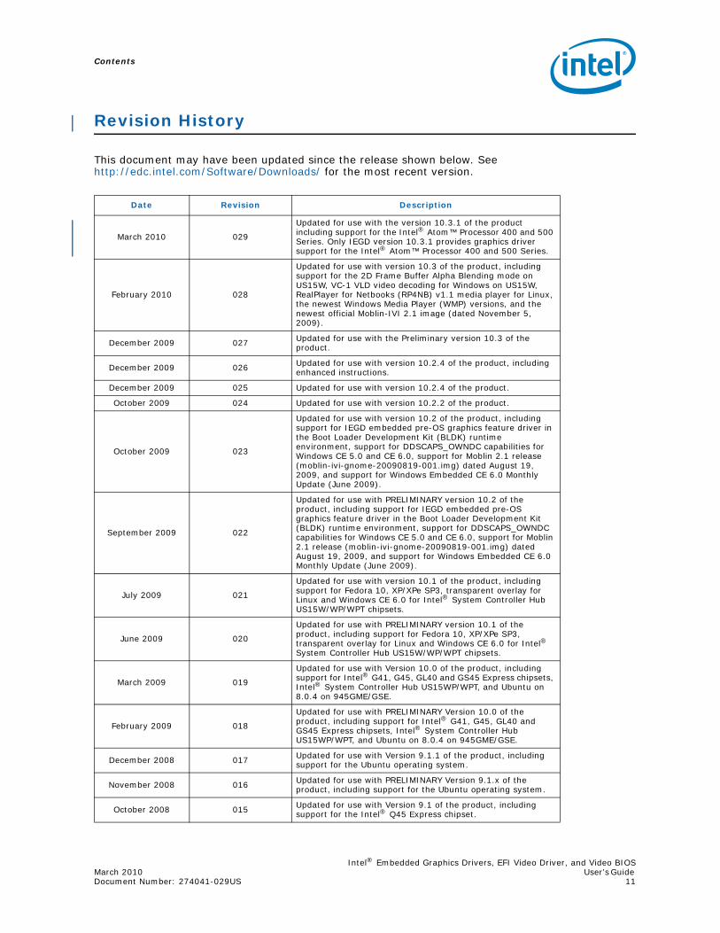
This document may have been updated since the release shown below. See http://edc.intel.com/Software/Downloads/ for the most recent version.
Date Revision Description
March 2010 029
Updated for use with the version 10.3.1 of the product including support for the Intel® Atom™ Processor 400 and 500 Series. Only IEGD version 10.3.1 provides graphics driver support for the Intel® Atom™ Processor 400 and 500 Series.
February 2010 028
Updated for use with version 10.3 of the product, including support for the 2D Frame Buffer Alpha Blending mode on US15W, VC-1 VLD video decoding for Windows on US15W, RealPlayer for Netbooks (RP4NB) v1.1 media player for Linux, the newest Windows Media Player (WMP) versions, and the newest official Moblin-IVI 2.1 image (dated November 5, 2009).
December 2009 027 Updated for use with the Preliminary version 10.3 of the product.
December 2009 026 Updated for use with version 10.2.4 of the product, including enhanced instructions.
December 2009 025 Updated for use with version 10.2.4 of the product.
October 2009 024 Updated for use with version 10.2.2 of the product.
October 2009 023
Updated for use with version 10.2 of the product, including support for IEGD embedded pre-OS graphics feature driver in the Boot Loader Development Kit (BLDK) runtime environment, support for DDSCAPS_OWNDC capabilities for Windows CE 5.0 and CE 6.0, support for Moblin 2.1 release (moblin-ivi-gnome-20090819-001.img) dated August 19, 2009, and support for Windows Embedded CE 6.0 Monthly Update (June 2009).
September 2009 022
Updated for use with PRELIMINARY version 10.2 of the product, including support for IEGD embedded pre-OS graphics feature driver in the Boot Loader Development Kit (BLDK) runtime environment, support for DDSCAPS_OWNDC capabilities for Windows CE 5.0 and CE 6.0, support for Moblin 2.1 release (moblin-ivi-gnome-20090819-001.img) dated August 19, 2009, and support for Windows Embedded CE 6.0 Monthly Update (June 2009).
July 2009 021
Updated for use with version 10.1 of the product, including support for Fedora 10, XP/XPe SP3, transparent overlay for Linux and Windows CE 6.0 for Intel® System Controller Hub US15W/WP/WPT chipsets.
June 2009 020
Updated for use with PRELIMINARY version 10.1 of the product, including support for Fedora 10, XP/XPe SP3, transparent overlay for Linux and Windows CE 6.0 for Intel® System Controller Hub US15W/WP/WPT chipsets.
March 2009 019
Updated for use with Version 10.0 of the product, including support for Intel® G41, G45, GL40 and GS45 Express chipsets, Intel® System Controller Hub US15WP/WPT, and Ubuntu on 8.0.4 on 945GME/GSE.
February 2009 018
Updated for use with PRELIMINARY Version 10.0 of the product, including support for Intel® G41, G45, GL40 and GS45 Express chipsets, Intel® System Controller Hub US15WP/WPT, and Ubuntu on 8.0.4 on 945GME/GSE.
December 2008 017 Updated for use with Version 9.1.1 of the product, including support for the Ubuntu operating system.
November 2008 016 Updated for use with PRELIMINARY Version 9.1.x of the product, including support for the Ubuntu operating system.
October 2008 015 Updated for use with Version 9.1 of the product, including support for the Intel® Q45 Express chipset.

Contents
Intel® Embedded Graphics Drivers, EFI Video Driver, and Video BIOSUser’s Guide March 2010 12 Document Number: 274041-029US
§ §
June 2008 014
Updated for use with Version 9.0 of the product, including support for the Intel® System Controller Hub US15W, Mobile Intel® GM45 Express chipset (2D only), and Mobile Intel® GLE960 Express chipset.
October 2007 013 Updated for use with Version 8.0 of the product, including support for the Intel® Q35.
June 2007 012Updated for use with Version 7.0 of the product, including support for the Intel® Mobile Intel® GME965 and Mobile Intel® 910GMLE chipsets.
December 2006 011 Updated for use with Version 6.1 of the product.
September 2006 010 Updated for use with Version 6.0 of the product, including support for the Intel® Q965 and Damn Small Linux*.
June 2006 009
Updated for use with Version 5.1 of the product, including support for the Texas Instruments TFP410* DVO encoder, Microsoft Windows Embedded for Point of Service (WEPOS)* operating system, and SuSE 10.
February 2006 008
Updated for use with Version 5.0 of the product, including support for the Intel® 852GM, Intel® 945G, and Intel® 945GM chipsets, the Silicon Image SiI 1362* and SiI 1364* sDVO transmitters, and External PCI as a Primary graphics adaptor.
October 2005 007 Updated for use with Version 4.1 of the product.
June 2005 006
Updated for use with Version 4.0 of the product, including support for the Intel® 915GV and Intel® 915GM chipsets, the Chrontel CH7307* and Chrontel CH7308* sDVO transmitters, and Advanced EDID Configuration.
May 2005 005Updated for use with Version 3.4 of the product, including use of the enhanced Video BIOS, Windows* installer/uninstaller, runtime configuration GUIs, and display discovery feature.
July 2004 004 Updated for use with Version 3.2 of the product, including use of the dynamic port driver feature.
May 2004 003Updated for usage with version 3.1 of the product, including details on PCF format and usage, Universal INF format, and updates to the User Build System.
February 2004 002 Updated chipset support to reflect current Embedded IA32 roadmap.
February 2004 001 Initial Release
Date Revision Description

Intel® Embedded Graphics Drivers, EFI Video Driver, and Video BIOSMarch 2010 User’s GuideDocument Number: 274041-029US 13
Introduction
1.0 Introduction
The Intel® Embedded Graphics Drivers (IEGD) comprise a suite of multi-platform graphics drivers designed to meet the requirements of embedded applications. Featuring Intel® Dynamic Display Configuration Technology (DDCT), the drivers run on the following Embedded Intel® Architecture (eIA) chipsets:
• Intel® Atom™ Processor 400 and 500 Series (CPU+GPU combination)
• Intel® Q45/G41/G45 Express chipset
• Intel® GM45/GL40/GS45 Express chipset
• Intel® System Controller Hub US15W/US15WP/WPT chipset
• Intel® Q35 Express chipset
• Mobile Intel® GLE960/GME965 Express chipset
• Intel® Q965 Express chipset
• Mobile Intel® 945GSE Express chipset
• Mobile Intel® 945GME Express chipset
• Intel® 945G Express chipset
• Intel® 915GV Express chipset
• Mobile Intel® 915GME Express chipset
• Mobile Intel® 910GMLE Express chipset
Note: If you need support for a chipset that is not listed above but is in the same family as those listed, please contact your Intel representative.
The IEGD supports five types of display devices:
• Analog CRT
• LVDS flat panels
• TMDS DVI displays
• HDMI
• TV Output
The IEGD is designed to work with fixed-function systems, such as Point-of-Sale (POS) devices, ATM machines, gaming devices, In-vehicle Information/Entertainment systems, etc. It can be configured to work with various hardware and software systems and supports both Microsoft Windows* and Linux* operating systems, including embedded versions of these operating systems.
The Intel Embedded Graphics Suite consists of both the IEGD and a Video BIOS (VBIOS) component. These two components are configurable and work together to provide a wide range of features. This document provides information on configuring and using both the IEGD and the VBIOS.

Introduction
Intel® Embedded Graphics Drivers, EFI Video Driver, and Video BIOSUser’s Guide March 2010 14 Document Number: 274041-029US
The IEGD provides the following features:
• Enhanced VBIOS and EFI support
• Dynamic Port Drivers
• Support for Dual Independent Head (DIH) displays
• Support of a Universal INF file
• EDID and EDID-less display support
• Display discovery and initialization
• Direct 3D* support
• Installer/Uninstaller GUI for Microsoft Windows* OS
• Runtime configuration GUI for Microsoft Windows OS and Linux OS
• OpenGL and OpenGL ES supported in specific chipsets and OS (refer to Appendix D for details)
1.1 Purpose
This manual provides information on both firmware and software, providing hardware design considerations, installation requirements, and static configuration options.
1.2 Intended Audience
This document is targeted at all platform and system developers who need to interface with the graphics subsystem. This includes, but is not limited to: platform designers, system BIOS developers, system integrators, original equipment manufacturers, system control application developers, as well as end users.
1.3 Related Documents
The following documents provide additional information on the hardware supported by the IEGD.
• Intel® Atom™ Processor 400 and 500 Series Datasheets – Volume One (Document Number 322847) and Volume Two (Document Number 322848)
• Intel® Embedded Graphics Drivers Version 10.3.1(Document Number: 315587)
• Intel® Embedded Graphics Drivers Version 10.3.1 Feature Matrix(Document Number: 317416)
• Intel® Atom™ Processor Z5xx Series Datasheet (Document Number: 319535)
• Intel® System Controller Hub (Intel® SCH) Datasheet(Document Number:319537)
• Intel® 35 Express Chipset Family Datasheet(Document Number: 31696602)
• Intel® I/O Controller Hub 9 (ICH9) Family Datasheet (Document Number:31696602)
• Mobile Intel® GME965 Express Family Chipset for Embedded Datasheet(Document Number: 31627303)
• Mobile Intel® 965 Express Chipset Family Datasheet(Document Number: 316273)
Intel® Embedded Graphics Drivers, EFI Video Driver, and Video BIOSMarch 2010 User’s GuideDocument Number: 274041-029US 15
Introduction
• Intel® 965 Express Chipset Family Datasheet(Document Number: 313053)
• Mobile Intel® 915PM/GM/GMS and 910GML Express Chipset Datasheet(Document Number: 305264)
• Intel® 915G/915GV/915P Express Chipset Datasheet(Document Number: 304467)
• Intel® I/O Controller Hub 6 (ICH6) Family Datasheet(Document Number: 301473)
• IEGD Linux Kernel Module Porting and Patching Methods White Paper(Document Number: 435867)
• Integrated Dual Independent Display on Intel® Digital Security Surveillance Multifunction Platforms Application Brief
• Display Panel Debugging with the Intel Graphics Memory Controller Hub(Document Number: 305964)
• Hybrid Multi-monitor Support; Enabling new usage models for Intel® Embedded Platforms White Paper (Document Number: 323214)
• VESA BIOS Extensions/Display Data Channel Standard, available at the following Web address:http://www.vesa.org/Standards/summary/1999_11.htm
This document provides information on the 4F VBE functions, which are supported by the Intel embedded Video BIOS.
• VESA BIOS Extension (VBE) Core Functions Standard Version 3.0, available at the following Web address:http://www.vesa.org/Standards/summary/1998_9a.htm
Contains information on the VESA BIOS Extension (VBE) specification for standard software access to graphics display controllers that support resolutions, color depths, and framebuffer organizations beyond the VGA hardware standard.
1.4 Conventions
The following conventions are used throughout this document.
Boldface Represents text that you type and text that appears on a screen.
Italics Introduces new terms and titles of documents.
Courier New Identifies the names of files, executable program names, and text that appears in a file.
Angle Brackets (<>) Encloses variable values in syntax or value ranges that you must replace with actual values.
Vertical Bar ( | ) Used to separate choices (for example, TRUE | FALSE)

Introduction
Intel® Embedded Graphics Drivers, EFI Video Driver, and Video BIOSUser’s Guide March 2010 16 Document Number: 274041-029US
1.5 New Features for Version 10.3.1
The table below presents new IEGD features and capabilities.
This release also contains resolutions for errata. For details on errata, including status information, refer to the specification update located at the Intel Premier Support Web site (premier.intel.com) and the Intel® Embedded Design Center (http://edc.intel.com).
1.6 Acronyms and Terminology
The table below lists the acronyms and terminology used throughout this document.
Table 1. IEGD v10.3.1 New Features
New Features
Graphics Driver support for Intel® Atom™ Processor 400 and 500 Series. Operating systems supported for Intel® Atom™ Processor 400 and 500 Series by IEGD v10.3.1 are:• Microsoft: Windows XP (SP3), Windows XP Embedded (SP3), Windows Embedded for Point of Service,
Windows Embedded CE 6.0 R2— Includes DirectDraw (DirectX* 9.0c, DirectX 8.1, DirectX 3), Direct3D* (DirectX 9.0c, DirectX 8.1)
and DirectX Texture Compression (DXTC)
• Linux: Fedora* 10 (kernel 2.6.27, X.org 1.5)— Includes OpenGL 1.4
• DOS* Support (IBM PC 2000,* MS 6.22)
Registry key set by default to enable software rendering for user interface content based on the Windows Presentation Foundation (WPF) graphical subsystem. This allows for better WPF rendering performance and lower CPU Utilization; for US15W only.
Hybrid multi-monitor support defined as a PCI- and PCI Express*-based graphics card operating concurrently with Intel’s chipset’s integrated graphics is supported fully with IEGD and the Q45/G41/G45 and GM45/GL40/GS45 chipsets (see Section 3.15 for details)
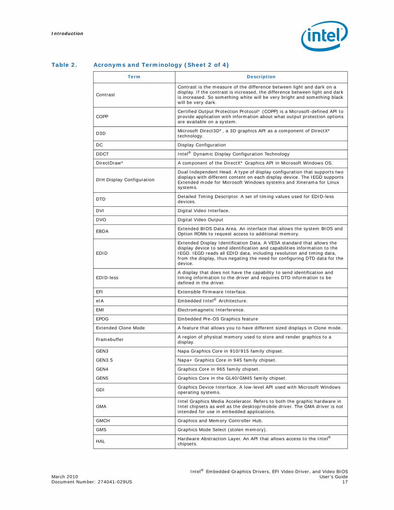
Table 2. Acronyms and Terminology (Sheet 1 of 4)
Term Description
ADD Card
APG Digital Display. An adapter card that can be inserted into the PCIe x16 port of Intel chipset family-based systems. ADD cards allow configurations for TV-out, LVDS, and TMDS output (i.e., televisions, digital displays, and flat panel displays).
AIM Add In Module.
API Application Programming Interface.
BDABIOS Data Area. A storage area that contains information about the current state of a display, including mode number, number of columns, cursor position, etc.
BIOSBasic Input/Output System. The IEGD interacts with two BIOS systems: system BIOS and Video BIOS (VBIOS). VBIOS is a component of the system BIOS.
BLDK Boot Loader Development Kit
CED
Configuration EDitor. Graphical pre-installation utility allows easy creation of consolidated driver installation packages for Windows*, Windows CE*, and Linux *operating systems, and VBIOS across numerous platforms and display combinations.
Clone Display Configuration
A type of display configuration that drives two display devices, each displaying the same content, but can have different resolutions and (independent) timings. Compare Twin Display Configuration and DIH Display Configuration.
Intel® Embedded Graphics Drivers, EFI Video Driver, and Video BIOSMarch 2010 User’s GuideDocument Number: 274041-029US 17
Introduction
Contrast
Contrast is the measure of the difference between light and dark on a display. If the contrast is increased, the difference between light and dark is increased. So something white will be very bright and something black will be very dark.
COPPCertified Output Protection Protocol* (COPP) is a Microsoft-defined API to provide application with information about what output protection options are available on a system.
D3D Microsoft Direct3D*, a 3D graphics API as a component of DirectX* technology.
DC Display Configuration
DDCT Intel® Dynamic Display Configuration Technology
DirectDraw* A component of the DirectX* Graphics API in Microsoft Windows OS.
DIH Display Configuration
Dual Independent Head. A type of display configuration that supports two displays with different content on each display device. The IEGD supports Extended mode for Microsoft Windows systems and Xinerama for Linux systems.
DTD Detailed Timing Descriptor. A set of timing values used for EDID-less devices.
DVI Digital Video Interface.
DVO Digital Video Output
EBDA Extended BIOS Data Area. An interface that allows the system BIOS and Option ROMs to request access to additional memory.
EDID
Extended Display Identification Data. A VESA standard that allows the display device to send identification and capabilities information to the IEGD. IEGD reads all EDID data, including resolution and timing data, from the display, thus negating the need for configuring DTD data for the device.
EDID-lessA display that does not have the capability to send identification and timing information to the driver and requires DTD information to be defined in the driver.
EFI Extensible Firmware Interface.
eIA Embedded Intel® Architecture.
EMI Electromagnetic Interference.
EPOG Embedded Pre-OS Graphics feature
Extended Clone Mode A feature that allows you to have different sized displays in Clone mode.
Framebuffer A region of physical memory used to store and render graphics to a display.
GEN3 Napa Graphics Core in 910/915 family chipset.
GEN3.5 Napa+ Graphics Core in 945 family chipset.
GEN4 Graphics Core in 965 family chipset.
GEN5 Graphics Core in the GL40/GM45 family chipset.
GDI Graphics Device Interface. A low-level API used with Microsoft Windows operating systems.
GMAIntel Graphics Media Accelerator. Refers to both the graphic hardware in Intel chipsets as well as the desktop/mobile driver. The GMA driver is not intended for use in embedded applications.
GMCH Graphics and Memory Controller Hub.
GMS Graphics Mode Select (stolen memory).
HAL Hardware Abstraction Layer. An API that allows access to the Intel® chipsets.
Table 2. Acronyms and Terminology (Sheet 2 of 4)
Term Description

Introduction
Intel® Embedded Graphics Drivers, EFI Video Driver, and Video BIOSUser’s Guide March 2010 18 Document Number: 274041-029US
HDCPHigh-bandwidth Digital-Content Protection, a specification that uses the DVI interface. HDCP encrypts the transmission of digital content between the video source, or transmitter and the digital display, or receiver.
HDMI High-Definition Multimedia Interface, an uncompressed, all-digital audio/video interface.
IAL Interface Abstraction Layer. An API that allows access to graphics interfaces including the GDI, and DirectDraw*.
iDCT Inverse Discrete Cosine Transformation (Hardware feature).
IEGD Intel® Embedded Graphics Drivers
IEGS Intel® Embedded Graphics Suite. Runtime graphics driver plus a VBIOS component.
IKM IEGD Kernel Module
INF file
A standard Microsoft Windows text file, referred to as an information file, used by Microsoft Windows OS to provide information to the driver. The default .inf file for the IEGD is iegd.inf. You can create customized parameters using the CED utility.
LPCMLinear Pulse Code Modulation (LPCM) is a method of encoding audio information digitally. The term also refers collectively to formats using this method of encoding.
LVDS Low Voltage Differential Signaling. Used with flat panel displays, such as a laptop computer display.
NTSCNational Television Standards Committee. An analog TV standard used primarily in North and Central America, Japan, the Philippines, South Korea, and Taiwan.
OAL Operating System Abstraction Layer. An API that provides access to operating systems, including Microsoft Windows and Linux.
Option ROM (OROM)Code which is integrated with the system BIOS and resides on a flash chip on the motherboard. The Intel Embedded Video BIOS is an example of an option ROM.
OS Operating System
PAL Phase Alternating Lines. An analog TV standard used in Europe, South America, Africa, and Australia.
PCF Parameters Configuration File
PCI Peripheral Component Interface.
Port Driver A driver used with the sDVO interfaces of the Graphics and Memory Controller Hub (GMCH).
POST Power On Self Test.
PWM Pulse Width Modulation.
Reserved Memory
A region of physical memory in a Windows CE* system set aside for BIOS, VBIOS, and Graphics Driver operations. Reserved memory can be configured to be used by the operating system and other applications when not in use by the BIOS.
Saturation
Monitors and scanners are based on the “additive” color system using RGB, starting with black and then adding Red, Green, and Blue to achieve color. Full saturation of RGB gives the perception of white, and images are created that radiate varying amounts of RGB, or varying saturation of RGB.
SCART
French Acronym - Syndicat des Constructeurs d'Appareils Radiorecepterus et Televiseurs. A video interface possessing up to four analog signals (Red/Green/Blue/Composite PAL). S-Video (Luma/Chroma) is possible over the SCART interface as well.
SCS Software Compliance Statement
Table 2. Acronyms and Terminology (Sheet 3 of 4)
Term Description
Intel® Embedded Graphics Drivers, EFI Video Driver, and Video BIOSMarch 2010 User’s GuideDocument Number: 274041-029US 19
Introduction
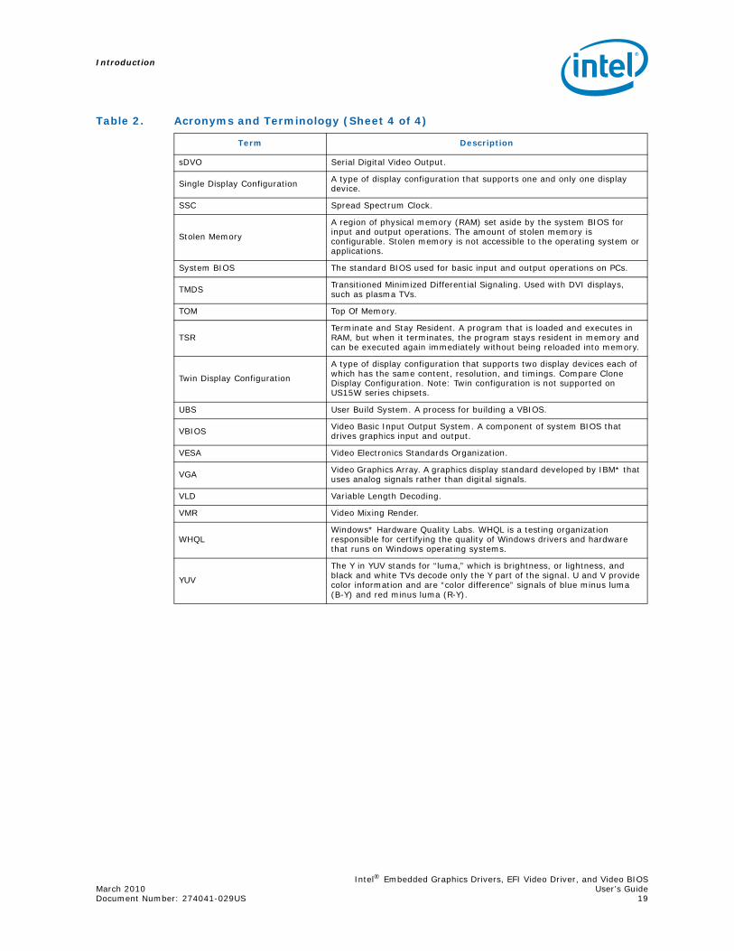
sDVO Serial Digital Video Output.
Single Display Configuration A type of display configuration that supports one and only one display device.
SSC Spread Spectrum Clock.
Stolen Memory
A region of physical memory (RAM) set aside by the system BIOS for input and output operations. The amount of stolen memory is configurable. Stolen memory is not accessible to the operating system or applications.
System BIOS The standard BIOS used for basic input and output operations on PCs.
TMDS Transitioned Minimized Differential Signaling. Used with DVI displays, such as plasma TVs.
TOM Top Of Memory.
TSRTerminate and Stay Resident. A program that is loaded and executes in RAM, but when it terminates, the program stays resident in memory and can be executed again immediately without being reloaded into memory.
Twin Display Configuration
A type of display configuration that supports two display devices each of which has the same content, resolution, and timings. Compare Clone Display Configuration. Note: Twin configuration is not supported on US15W series chipsets.
UBS User Build System. A process for building a VBIOS.
VBIOS Video Basic Input Output System. A component of system BIOS that drives graphics input and output.
VESA Video Electronics Standards Organization.
VGA Video Graphics Array. A graphics display standard developed by IBM* that uses analog signals rather than digital signals.
VLD Variable Length Decoding.
VMR Video Mixing Render.
WHQLWindows* Hardware Quality Labs. WHQL is a testing organization responsible for certifying the quality of Windows drivers and hardware that runs on Windows operating systems.
YUV
The Y in YUV stands for “luma,” which is brightness, or lightness, and black and white TVs decode only the Y part of the signal. U and V provide color information and are “color difference” signals of blue minus luma (B-Y) and red minus luma (R-Y).
Table 2. Acronyms and Terminology (Sheet 4 of 4)
Term Description

Introduction
Intel® Embedded Graphics Drivers, EFI Video Driver, and Video BIOSUser’s Guide March 2010 20 Document Number: 274041-029US
1.7 Downloading the IEGD and Video BIOS
The IEGD and the Video BIOS (VBIOS) are available on Intel Premier Support (QuAD) (premier.intel.com) and the Intel Embedded Design Center (http://edc.intel.com/Software/Downloads/IEGD/#download) only. The download package includes:
• IEGD drivers and VBIOS for Linux* operating systems and all Windows* operating systems
• Intel Embedded Graphics Driver Configuration Editor (CED) release which includes an online help system
Note: CED currently runs only on Windows operating systems.
Note: The Embedded Video BIOS version 10.3.1 is recommended for use with each of the graphics drivers in most cases. Click the following link to see the FAQ page for details on the differences of these versions.
http://edc.intel.com/Software/Downloads/IEGD/#faqs
After you have downloaded, installed, and run CED, you can configure and customize the drivers and VBIOS following the procedures in this document. Once they have been configured, you can integrate the VBIOS with the system BIOS ROM and install the IEGD on your operating system.
Intel® Embedded Graphics Drivers, EFI Video Driver, and Video BIOSMarch 2010 User’s Guide Document Number: 274041-029US 21
Architectural Overview
2.0 Architectural Overview
2.1 Introduction
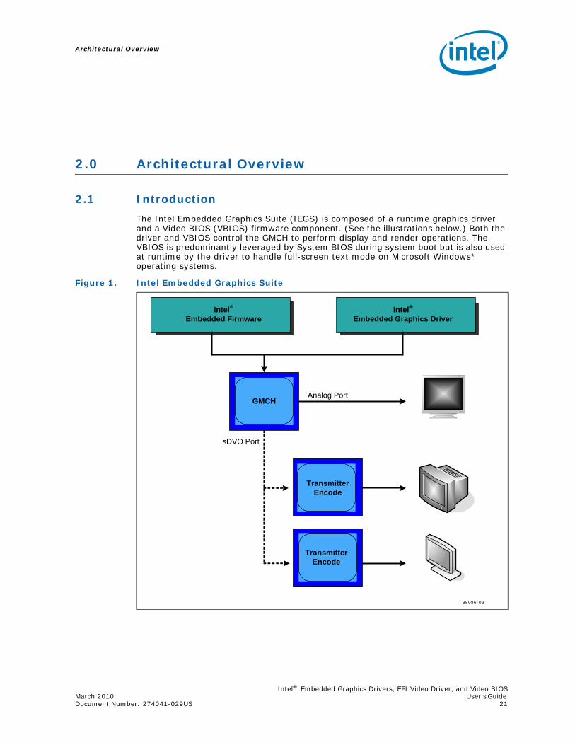
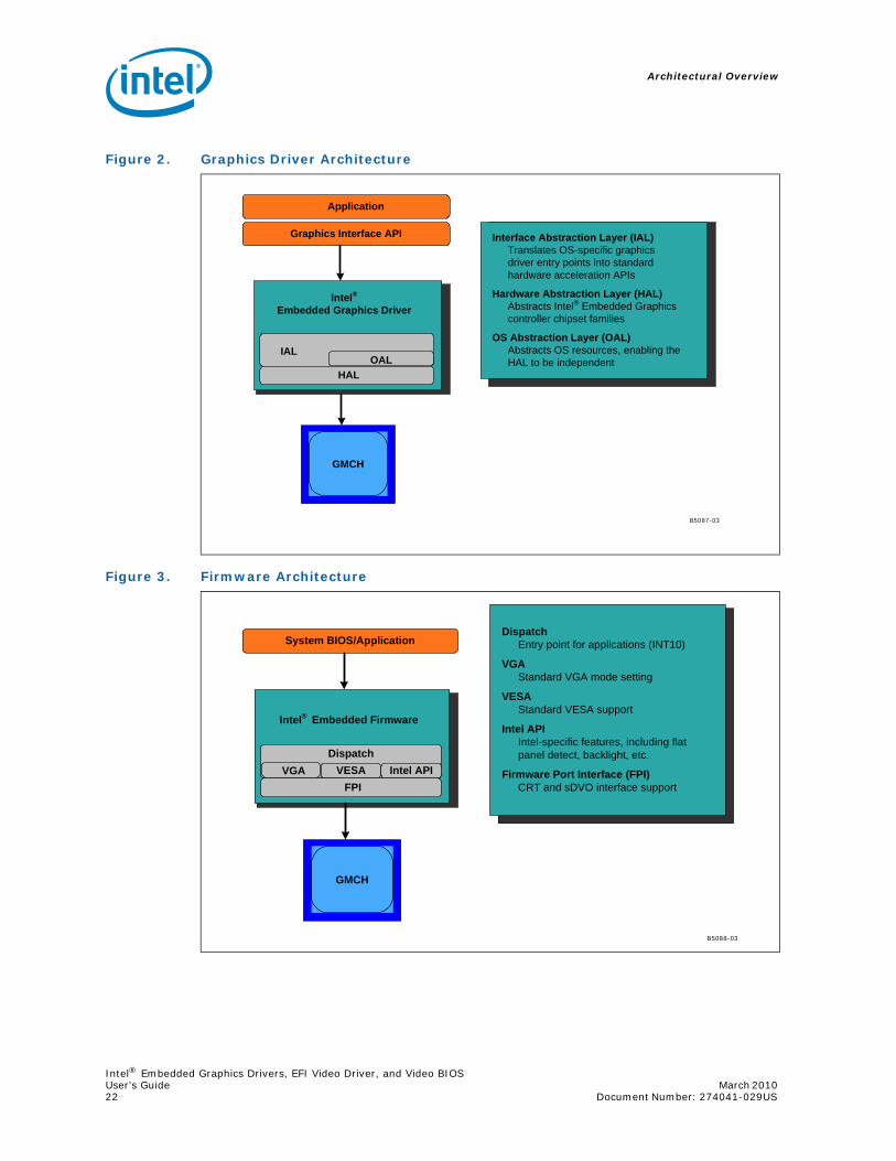
The Intel Embedded Graphics Suite (IEGS) is composed of a runtime graphics driver and a Video BIOS (VBIOS) firmware component. (See the illustrations below.) Both the driver and VBIOS control the GMCH to perform display and render operations. The VBIOS is predominantly leveraged by System BIOS during system boot but is also used at runtime by the driver to handle full-screen text mode on Microsoft Windows* operating systems.
Figure 1. Intel Embedded Graphics Suite
Intel®Embedded Firmware
Intel®Embedded Graphics Driver
GMCHAnalog Port
sDVO Port
TransmitterEncode
TransmitterEncode
B5086-03
Architectural Overview
Intel® Embedded Graphics Drivers, EFI Video Driver, and Video BIOSUser’s Guide March 2010 22 Document Number: 274041-029US
Figure 2. Graphics Driver Architecture
Figure 3. Firmware Architecture
GMCH
Graphics Interface API
Application
Interface Abstraction Layer (IAL)Translates OS-specific graphicsdriver entry points into standardhardware acceleration APIs
Hardware Abstraction Layer (HAL)Abstracts Intel® Embedded Graphicscontroller chipset families
OS Abstraction Layer (OAL)Abstracts OS resources, enabling theHAL to be independent
B5087-03
Intel®Embedded Graphics Driver
IALOAL
HAL
GMCH
Intel® Embedded Firmware
VESA Intel APIFPI
System BIOS/ApplicationDispatch
Entry point for applications (INT10)
VGAStandard VGA mode setting
VESAStandard VESA support
Intel APIIntel-specific features, including flatpanel detect, backlight, etc.
Firmware Port Interface (FPI)CRT and sDVO interface support
B5088-03
VGADispatch
Intel® Embedded Graphics Drivers, EFI Video Driver, and Video BIOSMarch 2010 User’s Guide Document Number: 274041-029US 23
Architectural Overview
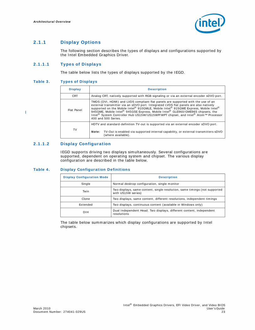
2.1.1 Display Options
The following section describes the types of displays and configurations supported by the Intel Embedded Graphics Driver.
2.1.1.1 Types of Displays
The table below lists the types of displays supported by the IEGD.
2.1.1.2 Display Configuration
IEGD supports driving two displays simultaneously. Several configurations are supported, dependent on operating system and chipset. The various display configuration are described in the table below.
The table below summarizes which display configurations are supported by Intel chipsets.
Table 3. Types of Displays
Display Description
CRT Analog CRT, natively supported with RGB signaling or via an external encoder sDVO port.
Flat Panel
TMDS (DVI, HDMI) and LVDS compliant flat panels are supported with the use of an external transmitter via an sDVO port. Integrated LVDS flat panels are also natively supported on the Mobile Intel® 910GMLE, Mobile Intel® 915GME Express, Mobile Intel® 945GME, Mobile Intel® 945GSE Express, Mobile Intel® GLE960/GME965 chipsets, the Intel® System Controller Hub US15W/US15WP/WPT chipset, and Intel® Atom™ Processor 400 and 500 Series.
TV
HDTV and standard-definition TV-out is supported via an external encoder sDVO port.
Note: TV-Out is enabled via supported internal capability, or external transmitters sDVO (where available).
Table 4. Display Configuration Definitions
Display Configuration Mode Description
Single Normal desktop configuration, single monitor
Twin Two displays, same content, single resolution, same timings (not supported with US15W series)
Clone Two displays, same content, different resolutions, independent timings
Extended Two displays, continuous content (available in Windows only)
DIH Dual Independent Head. Two displays, different content, independent resolutions

Architectural Overview
Intel® Embedded Graphics Drivers, EFI Video Driver, and Video BIOSUser’s Guide March 2010 24 Document Number: 274041-029US
Twin and Clone modes are supported by IEGD through custom APIs. In contrast, Extended and DIH are supported natively by both Microsoft Windows and Linux operating systems (X.org*).
2.2 Features
The following sections describe major features supported by IEGD.
2.2.1 Chipsets Supported
The table below lists IEGD-supported chipsets.
All supported chipsets provide support for a single analog output for CRTs. In addition, digital monitors, flat panels and TVs are supported through the GMCH sDVO interface.
Table 5. Supported Display Configurations
ChipsetOperating System
Windows XP* Windows CE* Linux
Intel® US15W/US15WP/WPT, Intel®PNV
Single, Clone, Extended
Single, Clone, Vertical Extended
Single, Clone, Xinerama, DIH
Intel® Q45/G41/G45Intel® GM45/GL40/GS45,Intel® Q35,Intel® GLE960,Intel® GME965,Intel® Q965,Intel® 945GM,Intel® 945G,Intel® 915GME,Intel® 910GMLE
Single, Twin, Clone, Extended Single, Twin, Clone Single, Twin, Clone,
Xinerama, DIH
Intel® 915GV Single, Twin, Clone Single, Twin, Clone Single, Twin, Clone
Table 6. Chipsets Supported by the Intel Embedded Graphics Suite
Chipset IEGD VBIOS Support IEGD Support
Intel®PNV Yes Yes
Intel® Q45/G41/G45 Yes Yes
Intel® GM45/GL40/GS45 Yes Yes
Intel® US15W/US15WP/WPT Yes Yes
Intel® Q35 Yes Yes
Intel® GLE960/GME965,Intel® Q965
Yes Yes
Intel® 945GIntel 945GMEIntel 945GSE
YesYesYes
YesYesYes
Intel® 915GVIntel® 915GME
YesYes
YesYes
Intel® 910GMLE Yes Yes

Intel® Embedded Graphics Drivers, EFI Video Driver, and Video BIOSMarch 2010 User’s Guide Document Number: 274041-029US 25
Architectural Overview
2.2.2 OS and API Support
The IEGD and Video BIOS support the following operating systems and APIs. For OpenGL APIs, see Appendix D, “2D/3D API Support”.
• Linux X.org
• Wind River Linux* Platform for Infotainment, Red Hat Embedded Linux (Intel® System Controller Hub US15W/US15WP/WPT only), and Moblin 2.1 IVI
• Windows Embedded Standard 2009, Windows XP* ver. SP3, Windows XP Professional* ver. SP3, Windows XP Embedded* ver. SP3, WEPOS* ver. SP3:
— DirectX* 8.1 and 9.0 (DirectDraw* and Direct3D*)
• Microsoft Windows CE* 5.0 and 6.0 (Note that Intel® System Controller Hub US15W/US15WP/WPT chipsets and Intel® Atom™ Processor 400 and 500 Series do NOT support Windows CE 5.0)
Note: The following features are NOT supported in IEGD v10.3.1:
• Microsoft Vista* 2D + 3D
• Vista DirectX 9.0L, DirectX 10.0 (Combine with MS Vista 2D + 3D)
2.2.3 DisplayID Support
The Intel Embedded Graphics Driver supports the newly developed DisplayID specification. DisplayID is a new VESA specification (www.vesa.org) that describes the data format for the display configuration parameters and provides the capability to unify the display data structure thereby decreasing the need to rely on proprietary extensions. For more information on DisplayID, its uses and parameters please reference the VESA specification (www.vesa.org).
2.2.4 EDID-Less Configuration
EDID-less support is the ability to run a display panel that does not have display timing information within the panel. Therefore, the user has to provide the display timing information to the graphics drivers. For the IEGD, this must be done through:
• CED
• Configuration file for the graphics drivers.
This document describes only the necessary edits to the configuration files that are required to implement the graphics driver and VBIOS, and not specific settings for EDID-less panel configuration. Please refer to the manufacturer’s specifications for the DTD settings to use for your EDID-less panels.
2.2.4.1 EDID-Less Panel Type Detection
The Intel Embedded Graphics Suite supports EDID-less displays that do not export timing modes. This is accomplished by allowing configuration of a Detailed Timing Descriptor (DTD), and associating that DTD with a specific display port. The IEGD provides further flexibility in allowing numerous DTDs to be defined and having the selection of the DTD be configurable though selection of Configuration IDs. The selection of the Configuration ID can be done from the System BIOS, as long as it supports the Intel 5F40h function and passes the appropriate Configuration ID to the VBIOS. The VBIOS in turn notifies the Graphics Driver of which Configuration ID is active. This is not required however, but the VBIOS and/or Graphics Driver require the Configuration ID to be set prior to installation.

Architectural Overview
Intel® Embedded Graphics Drivers, EFI Video Driver, and Video BIOSUser’s Guide March 2010 26 Document Number: 274041-029US
2.2.5 sDVO Devices
The IEGD supports many third-party digital transmitters connected to the sDVO ports of the GMCH. The driver code that supports each of these devices is abstracted and is a separate driver called a port driver. Port drivers can be dynamically loaded at the time IEGD is initialized, and IEGD can be configured to allow any number of these port drivers to be loaded. By default, all the port drivers for the devices listed in the following table as Included in Release Package will be loaded by default if the corresponding transmitter is detected. If a port driver is not specified in the configuration before installation, that device will not be detected, and the port driver will not be loaded. The configuration can be modified before installation to prevent certain port drivers from being loaded or to include additional port drivers to load.
Table 7. SDVO Devices Supported
Device VBIOS/EPOG/EFI Video Driver Support
Graphics Driver Support
Internal LVDS Yes Yes
Internal TV Out No Yes
Chrontel CH7022* RGB VGA/SDTV/HDTV out Yes Yes
Chrontel CH7307* Single-port DVI out Yes Yes
Chrontel CH7308* LVDS out Yes Yes
Chrontel CH7317* RGB VGA out Yes Yes
Chrontel CH7315* HDMI out Yes Yes
Chrontel CH7319* Dual-port DVI out with HDCP Yes Yes
Chrontel CH7320* Dual-port DVI out Yes Yes
Silicon Image SiI 1362*Single-port DVI out Yes Yes
Silicon Image SiI 1364* Single-port DVI out Yes Yes
Intel® Embedded Graphics Drivers, EFI Video Driver, and Video BIOSMarch 2010 User’s Guide Document Number: 274041-029US 27
Architectural Overview
2.2.6 Rotation
Rotation is the ability to rotate the display for the Intel Embedded Graphics Driver. Rotation support includes 0°, 90°, 180°, 270°. Rotation is supported only on the following chipsets using Windows XP*, and Linux operating systems:
• Intel® Atom™ Processor 400 and 500 Series
• Intel® Q45/G41/G45 Express chipset
• Intel® GM45/GL40/GS45 Express chipset
• Intel® System Controller Hub US15W/US15WP/WPT chipset
• Intel® Q35 Express chipset
• Mobile Intel® GLE960/GME965 Express chipset
• Intel® Q965 Express chipset
• Mobile Intel® 945GSE Express chipset
• Mobile Intel® 945GME Express chipset
• Mobile Intel® 945GM Express chipset
• Intel® 945G Express chipset
• Intel® 915GV Express chipset
• Mobile Intel® 915GME Express chipset
• Mobile Intel® 910GMLE Express chipset
Note: Rotation is not supported with the VBIOS. Rotation is supported with Windows CE* but only in static mode.

This page is intentionally left blank.
Architectural Overview
Intel® Embedded Graphics Drivers, EFI Video Driver, and Video BIOSUser’s Guide March 2010 28 Document Number: 274041-029US

Intel® Embedded Graphics Drivers, EFI Video Driver, and Video BIOSMarch 2010 User’s GuideDocument Number: 274041-029US 29
Platform Configuration Using CED
3.0 Platform Configuration Using CED
The Intel® IEGD Configuration Editor (CED) is a Windows-based Graphical User Interface (GUI) that allows you to create configurations, package the configurations, and create installations that can be loaded directly on a specific OS or Video BIOS platform. Configurations are associated with a specific chipset and can be created for any one of the following supported chipsets:
• Intel® Atom™ Processor 400 and 500 Series
• Intel® Q45/G41/G45 Express chipset
• Intel® GM45/GL40/GS45 Express chipset
• Intel® System Controller Hub US15W/US15WP/WPT chipset
• Intel® Q35 Express chipset
• Mobile Intel® GLE960/GME965 Express chipset
• Intel® Q965 Express chipset
• Mobile Intel® 945GSE Express chipset
• Mobile Intel® 945GME Express chipset
• Intel® 945G Express chipset
• Intel® 915GV Express chipset
• Mobile Intel® 915GME Express chipset
• Mobile Intel® 910GMLE Express chipset
IEGD configurations can be created for the following supported operating systems and Video BIOS:
• Linux X.org
• Fedora 7 (not supported with the Intel® System Controller Hub US15W/US15WP/WPT chipset and Intel® Atom™ Processor 400 and 500 Series)
• Fedora 10
• Wind River Platform for Infotainment Linux and Red Hat Embedded Linux (Intel® System Controller Hub US15W/US15WP/WPT only), Ubuntu, and Moblin 2.1 IVI.
• Microsoft Windows Embedded Standard 2009*, Microsoft Windows XP* SP3, Microsoft Windows XP Professional* SP3, Microsoft Windows XP Embedded* SP3, and Microsoft WEPOS* SP3:
— DirectX* 8.1 and 9.0 (DirectDraw* and Direct3D*)
• Microsoft Windows CE 5.0 and 6.0 (Note that Intel® System Controller Hub US15W chipset does NOT support Windows CE 5.0)
Note: The following features are NOT supported in IEGD v10.3.1:
• Microsoft Vista* 2D + 3D (WDDM)
• Vista DirectX 9.0L, DirectX 10.0 (Combine with MS Vista 2D + 3D)
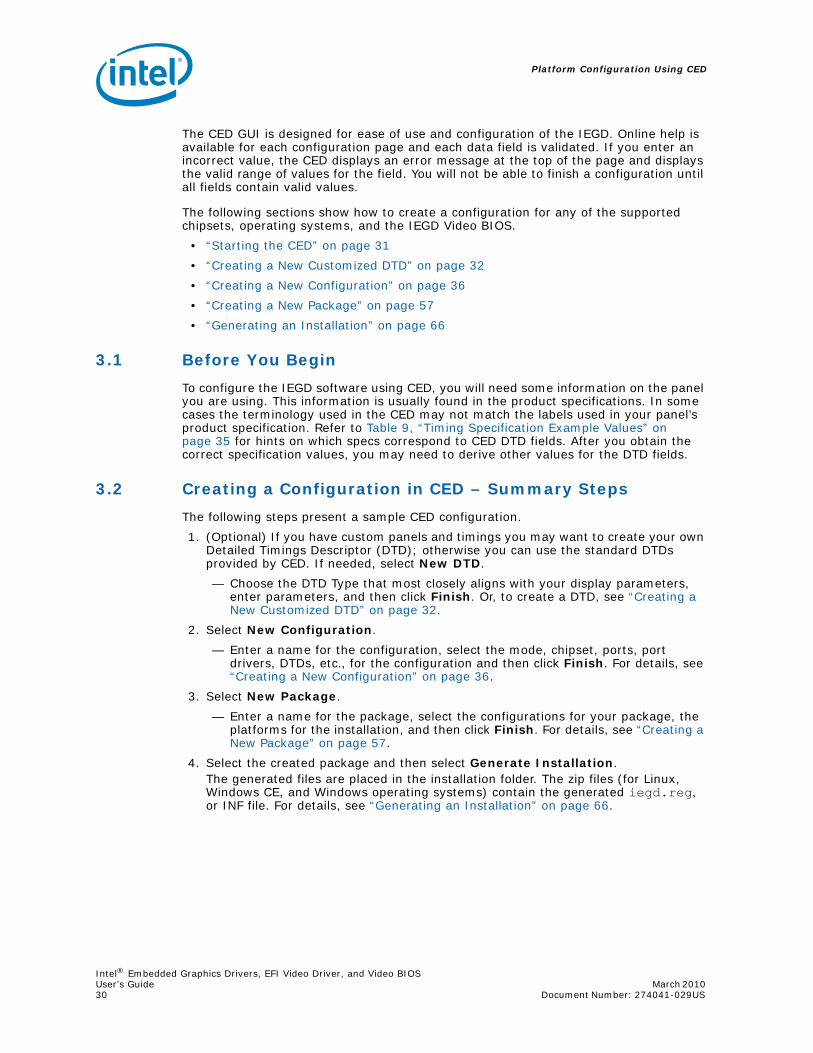
Platform Configuration Using CED
Intel® Embedded Graphics Drivers, EFI Video Driver, and Video BIOSUser’s Guide March 2010 30 Document Number: 274041-029US
The CED GUI is designed for ease of use and configuration of the IEGD. Online help is available for each configuration page and each data field is validated. If you enter an incorrect value, the CED displays an error message at the top of the page and displays the valid range of values for the field. You will not be able to finish a configuration until all fields contain valid values.
The following sections show how to create a configuration for any of the supported chipsets, operating systems, and the IEGD Video BIOS.
• “Starting the CED” on page 31
• “Creating a New Customized DTD” on page 32
• “Creating a New Configuration” on page 36
• “Creating a New Package” on page 57
• “Generating an Installation” on page 66
3.1 Before You Begin
To configure the IEGD software using CED, you will need some information on the panel you are using. This information is usually found in the product specifications. In some cases the terminology used in the CED may not match the labels used in your panel’s product specification. Refer to Table 9, “Timing Specification Example Values” on page 35 for hints on which specs correspond to CED DTD fields. After you obtain the correct specification values, you may need to derive other values for the DTD fields.
3.2 Creating a Configuration in CED – Summary Steps
The following steps present a sample CED configuration.
1. (Optional) If you have custom panels and timings you may want to create your own Detailed Timings Descriptor (DTD); otherwise you can use the standard DTDs provided by CED. If needed, select New DTD.
— Choose the DTD Type that most closely aligns with your display parameters, enter parameters, and then click Finish. Or, to create a DTD, see “Creating a New Customized DTD” on page 32.
2. Select New Configuration.
— Enter a name for the configuration, select the mode, chipset, ports, port drivers, DTDs, etc., for the configuration and then click Finish. For details, see “Creating a New Configuration” on page 36.
3. Select New Package.
— Enter a name for the package, select the configurations for your package, the platforms for the installation, and then click Finish. For details, see “Creating a New Package” on page 57.
4. Select the created package and then select Generate Installation.The generated files are placed in the installation folder. The zip files (for Linux, Windows CE, and Windows operating systems) contain the generated iegd.reg, or INF file. For details, see “Generating an Installation” on page 66.

Intel® Embedded Graphics Drivers, EFI Video Driver, and Video BIOSMarch 2010 User’s GuideDocument Number: 274041-029US 31
Platform Configuration Using CED
3.3 Starting the CED
To start the IEGD CED, open the folder where you installed the CED and click the iegd-ced.exe icon. The IEGD CED splash window appears for a few moments followed by the IEGD Configuration Editor main window.
Figure 4. Sample CED Configuration Start Page

Platform Configuration Using CED
Intel® Embedded Graphics Drivers, EFI Video Driver, and Video BIOSUser’s Guide March 2010 32 Document Number: 274041-029US
From this window, you can create configurations, package the configurations, and create installations from the packages that can be installed directly on a platform. The main window also provides a Console tab that displays information when you build a package or an installation.
The following sections show how to create a configuration for any of the supported chipsets, operating systems, and the IEGD Video BIOS.
3.4 Creating a New Customized DTD
CED allows you to create Dynamic Timings Definitions (DTD) for EDID-less displays or displays for which you do not want to use the display's EDID settings. In either of those cases, you can create your own DTD using the steps below. Otherwise you can use one of the standard DTDs included in CED.
You can create a new DTD by selecting the New DTD by clicking the New DTD link at the top of the main CED window, or you can create DTDs for each configured port when you create a new configuration. Any DTDs you create will be available for all configurations.
When you select New DTD from the main CED window, the following IEGD DTD Page appears.
Figure 5. IEGD Configuration Editor Main Window

Intel® Embedded Graphics Drivers, EFI Video Driver, and Video BIOSMarch 2010 User’s GuideDocument Number: 274041-029US 33
Platform Configuration Using CED
To create a custom DTD setting:
1. From the CED main screen, select New DTD.
2. Enter a name for the DTD in the text box provided, for example, test_LVDS.
3. Using the data sheet from the panel being used, enter the DTD timings in the appropriate fields. Refer to Table 8, “IEGD DTD Setting Options” for field descriptions.The screen will be similar to the example shown in Figure 6.
4. Click Finish.The custom DTD is complete.
Figure 6. IEGD DTD Page

Platform Configuration Using CED
Intel® Embedded Graphics Drivers, EFI Video Driver, and Video BIOSUser’s Guide March 2010 34 Document Number: 274041-029US
Table 8. IEGD DTD Setting Options (Sheet 1 of 2)
DTD Parameter Description
Enter DTD File NameEnter a name for this customized DTD. This is a required field and the name must be between 1 and 50 characters and may contain spaces and underscores.
DTD Type
Select the DTD Type that most closely aligns with your display parameters. Options are:• IEGD Parameters:
The IEGD Parameters are the same as the current PCF/CED DTD parameters.
• VESA Parameters:The VESA Parameters allow the user to create a DTD from a VESA monitor timing standard.
• Hardware Parameters:The Hardware Parameters are the parameters that are used by IEGD.
• Simple Parameters:The Simple Parameters (CVT Standard) is a process for computing standard timing specifications. The method for developing Reduced Blanking timings is not included.
• Mode Lines:The Mode Lines are a video timing spec used by X.org. The X.org timing setting for Mode Lines is “name” I A B C D E F G H. For example: “640x480@8bpp” 25.175 640 672 728 816 480 489 501 526.
• EDID Block:The EDID Block is the detailed timing section (18 bytes) of the basic 128-byte EDID data structure. The detailed timing section starts at 36h of the 128-byte EDID data structure. Enter the EDID block 1 byte at a time. Example: a0 0f 20 00 31 58 1c 20 d2 1a 14 00 f6 b8 00 00 00 18
Pixel Clock Pixel clock value in KHz. Range 0-0x7fffffff
DTD Settings Flags
This section allows you to set flags for Interlace, Vertical Sync Polarity, Horizontal Sync Polarity, and Blank Sync Polarity. Each field in this section is described below.Interlaced Display: • Check for Interlaced• Cleared for Non-interlaced
Vertical Sync Polarity:• Active Low (Default)• Active High
Horizontal Sync Polarity:• Active Low (Default)• Active High
Blank Sync Polarity:• Active Low (Default)• Active High
Note: These flags are IEGD-specific and do not correspond to VESA 3.0 flags.
Horizontal Sync Offset (Front Porch) in pixels
Specifies the amount of time after a line of the active video ends and the horizontal sync pulse starts (Horizontal Front Porch). Range 0-1023 [10 bits].
Horizontal Sync Pulse Width (Sync Time) in pixels
Width of the Horizontal Sync Pulse (Sync Time) which synchronizes the display and returns the beam to the left side of the display. Range 0-1023 [10 bits].
Horizontal Blank Width (Blank Time) in pixels
This parameter indicates the amount of time it takes to move the beam from the right side of the display to the left side of the display (Blank Time). During this time, the beam is shut off, or blanked. Range 0-4095 [12 bits].
Horizontal Active (Width) in pixels Number of pixels displayed on a horizontal line (Width). Range 1-32767 [15 bits].
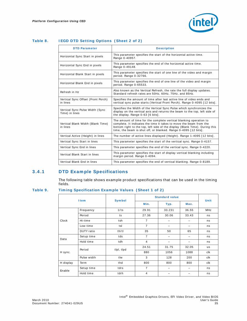
Intel® Embedded Graphics Drivers, EFI Video Driver, and Video BIOSMarch 2010 User’s GuideDocument Number: 274041-029US 35
Platform Configuration Using CED
3.4.1 DTD Example Specifications
The following table shows example product specifications that can be used in the timing fields.
Horizontal Sync Start in pixels This parameter specifies the start of the horizontal active time. Range 0-40957.
Horizontal Sync End in pixels This parameter specifies the end of the horizontal active time. Range 0-49148.
Horizontal Blank Start in pixels This parameter specifies the start of one line of the video and margin period. Range 0-32766.
Horizontal Blank End in pixels This parameter specifies the end of one line of the video and margin period. Range 0-65533.
Refresh in Hz Also known as the Vertical Refresh, the rate the full display updates. Standard refresh rates are 50Hz, 60Hz, 75Hz, and 85Hz.
Vertical Sync Offset (Front Porch) in lines
Specifies the amount of time after last active line of video ends and vertical sync pulse starts (Vertical Front Porch). Range 0-4095 [12 bits].
Vertical Sync Pulse Width (Sync Time) in lines
Specifies the Width of the Vertical Sync Pulse which synchronizes the display on the vertical axis and returns the beam to the top, left side of the display. Range 0-63 [6 bits].
Vertical Blank Width (Blank Time) in lines
The amount of time for the complete vertical blanking operation to complete. It indicates the time it takes to move the beam from the bottom right to the top, left side of the display (Blank Time). During this time, the beam is shut off, or blanked. Range 0-4095 [12 bits].
Vertical Active (Height) in lines The number of active lines displayed (Height). Range 1-4095 [12 bits].
Vertical Sync Start in lines This parameter specifies the start of the vertical sync. Range 0-4157.
Vertical Sync End in lines This parameter specifies the end of the vertical sync. Range 0-4220.
Vertical Blank Start in lines This parameter specifies the start of display vertical blanking including margin period. Range 0-4094.
Vertical Blank End in lines This parameter specifies the end of vertical blanking. Range 0-8189.
Table 8. IEGD DTD Setting Options (Sheet 2 of 2)
DTD Parameter Description
Table 9. Timing Specification Example Values (Sheet 1 of 2)
Item SymbolStandard value
UnitMin. Typ. Max.
Clock
Frequency 1/ts 29.91 33.231 36.55 MHz
Period ts 27.36 30.06 33.43 ns
Hi-time tsh 7 – – ns
Low-time tsl 7 – – ns
DUTY ratio th/tl 35 50 65 ns
DataSetup time tds 7 – – ns
Hold time tdh 4 – – ns
H sync.Period tlpl, tlpd
24.51 31.75 32.05 us
880 1056 1088 clk
Pulse width tlw 3 128 200 clk
H display Term thd 800 800 800 clk
EnableSetup time tdrs 7 – – ns
Hold time tdrh 4 – – ns
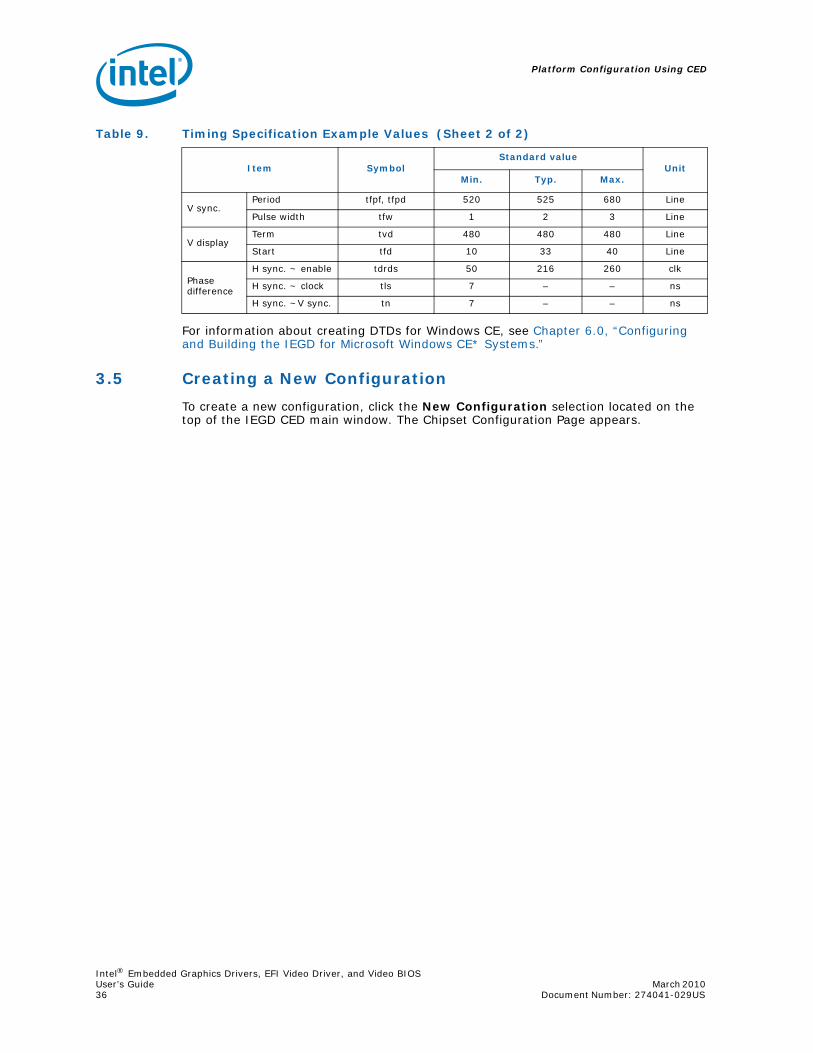
Platform Configuration Using CED
Intel® Embedded Graphics Drivers, EFI Video Driver, and Video BIOSUser’s Guide March 2010 36 Document Number: 274041-029US
For information about creating DTDs for Windows CE, see Chapter 6.0, “Configuring and Building the IEGD for Microsoft Windows CE* Systems.”
3.5 Creating a New Configuration
To create a new configuration, click the New Configuration selection located on the top of the IEGD CED main window. The Chipset Configuration Page appears.
V sync.Period tfpf, tfpd 520 525 680 Line
Pulse width tfw 1 2 3 Line
V displayTerm tvd 480 480 480 Line
Start tfd 10 33 40 Line
Phase difference
H sync. ~ enable tdrds 50 216 260 clk
H sync. ~ clock tls 7 – – ns
H sync. ~V sync. tn 7 – – ns
Table 9. Timing Specification Example Values (Sheet 2 of 2)
Item SymbolStandard value
UnitMin. Typ. Max.
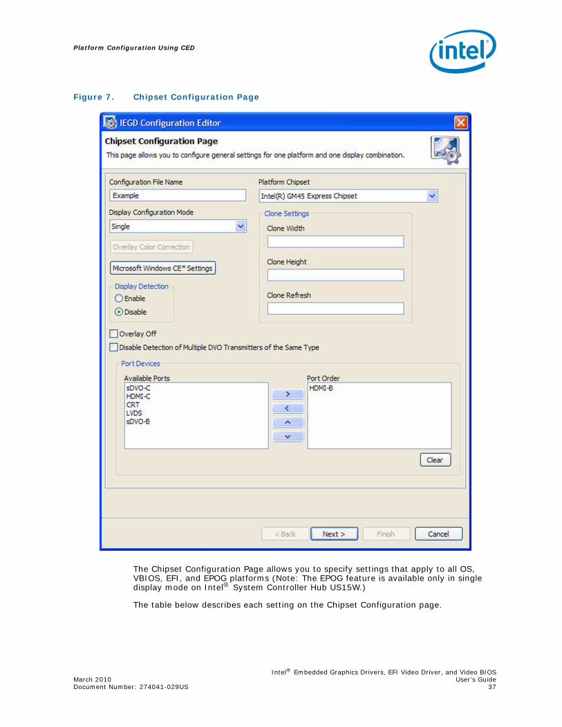
Intel® Embedded Graphics Drivers, EFI Video Driver, and Video BIOSMarch 2010 User’s GuideDocument Number: 274041-029US 37
Platform Configuration Using CED
The Chipset Configuration Page allows you to specify settings that apply to all OS, VBIOS, EFI, and EPOG platforms (Note: The EPOG feature is available only in single display mode on Intel® System Controller Hub US15W.)
The table below describes each setting on the Chipset Configuration page.
Figure 7. Chipset Configuration Page

Platform Configuration Using CED
Intel® Embedded Graphics Drivers, EFI Video Driver, and Video BIOSUser’s Guide March 2010 38 Document Number: 274041-029US
Table 10. Chipset Configuration Page Settings (Sheet 1 of 2)
Setting Description
Configuration File Name
Provide a name for the configuration you are creating. This name is required and is used when you create packages. The name can consist of any alphanumeric characters and any special characters and must be between 1 and 50 characters. You must enter a configuration before you can enter any other information on this page.
Platform Chipset Select the target chipset for this configuration from the drop-down list.
Display Configuration Mode
Select the type of display configuration from the drop-down list. You can select any one of the following display configurations:• Single — Single display configuration• Twin — Two displays where both displays have the same resolution,
refresh rate, and content• Clone — Two displays where both displays have the same content
but can have different resolutions and timings.• DIH — Dual Independent Head. This is a configuration where both
displays can have different resolutions, different refresh rates, and different content.
Note: On Microsoft Windows* DIH configurations, the display DOES NOT automatically come up in extended display mode. You must go into the Display properties on the Control Panel and manually set the display to DIH mode.
Overlay Color Correction
Overlay Color Correction allows the Overlay plane to have color-correction settings that are different from the main frame buffer color-correction settings. See “Overlay Color Correction” on page 39.Note: Overlay color correction is not supported on the Intel® GM45
chipset.
Microsoft Windows CE* Settings
If you are creating a package for a Microsoft Windows* CE platform, click the Microsoft Windows CE* Settings button for additional settings that may be required for your configuration. Please see “Changing Windows CE OS Options” on page 41 for descriptions of these settings.
Display Detection
Display Detection allows you to specify if the driver should detect displays on the system. The default is Disabled. For more information on Display Detection, refer to “Display Detection and Initialization” on page 78.
Port Devices (Available Ports, Port Order)
The Port Devices section lists the ports available based on the chipset selected.The Available Ports box lists the ports that are available. You can move these port devices to the Port Order box to determine the search order for detecting attached displays. To move a port device to the Port Order box, either double-click the port device or click the port device to highlight it, and then click the right arrow button to move it from the Available Ports to the Port Order box.The Port Order section allows you to determine the search order for detecting attached displays for the Display Detection feature. When Display Detection is enabled, the Port Order determines which display is primary and which display is secondary. You can choose default ordering by not moving any of the Available Ports to the Port Order box and leaving the Port Order box empty. Default ordering is chipset-specific. See Table 56, “Default Search Order” on page 222 for more information on default port ordering based on chipset.When you move one or more ports to the Port Order box, you can configure each port by clicking Next. For each port listed in the Port Order box, you can click Next to configure each port. See “Configuring Ports” on page 44 for information on configuring ports.
Note: When specifying the port order, if sDVOC is before sDVOB, you should specify the I2C parameter i2Cdab=0x72 for sDVOC. This allows the driver to detect the SDVO encoder connected to sDVOC properly. See other details in “i2cdab” on page 75.

Intel® Embedded Graphics Drivers, EFI Video Driver, and Video BIOSMarch 2010 User’s GuideDocument Number: 274041-029US 39
Platform Configuration Using CED
3.5.1 Setting Color Correction
Color Correction is available for both overlays and framebuffers, and is accessed under the New Configuration link at the top of the main CED window. For both overlay and framebuffer color correction, user-assigned values must be between 0.6 to 6. By default, gamma is 1.0 (no correction).
Note: Overlay color correction is not supported on the Intel® GM45/GL40/GS45 chipset.
3.5.1.1 Overlay Color Correction
Overlay Color Correction allows the Overlay plane to have color-correction settings that are different from the main framebuffer color-correction settings. This feature allows you to color-correct for red, green, and blue, plus it enables you to adjust brightness, contrast, and saturation.
To assign overlay color correction, click the Overlay Color Correction button on the Chipset Configuration Page. The Overlay Color Correction Page appears, as shown in the figure below.
Clone Settings Clone Width Clone Height Clone Refresh
If you are creating a clone display configuration, you can specify the width, height, and refresh rate for the clone display in this section. For more information about clone display configurations, refer to “Enhanced Clone Mode Support” on page 85.
Overlay Off
This field allows you disable Overlay support, which is enabled by default.
Note: This field is only for Microsoft Windows* and Microsoft Windows CE operating systems. The Linux* OS configuration for the xorg.conf provides a standard option that performs the same function.
Table 10. Chipset Configuration Page Settings (Sheet 2 of 2)
Setting Description
Table 11. Overlay Color Correction Values (applies to ALL color)
Gamma: 0.6 to 6.0 (default value is 1)
Brightness: 0 to 200 (default value is 100)
Contrast: 0 to 200 (default value is 100)
Saturation: 0 to 200 (default value is 100)

Platform Configuration Using CED
Intel® Embedded Graphics Drivers, EFI Video Driver, and Video BIOSUser’s Guide March 2010 40 Document Number: 274041-029US
Add your desired values to the correction fields and then click Finish.
3.5.1.2 Framebuffer Color Correction Attributes
Framebuffer Color Correction Attributes allow you to adjust the main color attributes. This feature allows you to color-correct for red, green, and blue, and enables you to adjust brightness and contrast.
To assign framebuffer color correction, click the Framebuffer Color Correction Attributes button on the port configuration page (CRT, LVDS, sDVO, or HDMI). The Framebuffer Color Correction Page appears, as shown in Figure 9.
Figure 8. Overlay Color Correction Page
Table 12. Framebuffer Color Correction Values (applies to R, G, B color)
Gamma: 0.6 to 6.0 (default value is 1)
Brightness: -127 to 127 (default value is 0)
Contrast: -127 to 127 (default value is 0)

Intel® Embedded Graphics Drivers, EFI Video Driver, and Video BIOSMarch 2010 User’s GuideDocument Number: 274041-029US 41
Platform Configuration Using CED
Add your desired values to the correction fields and then click Finish.
3.5.2 Changing Windows CE OS Options
The Windows CE Options Page allows you to enter Windows CE OS-specific options into the configuration. When you click the Microsoft Windows CE* Settings button from the IEGD Package Page (see “Creating a New Package” on page 57), the following page appears.
Figure 9. Framebuffer Color Correction Page

Platform Configuration Using CED
Intel® Embedded Graphics Drivers, EFI Video Driver, and Video BIOSUser’s Guide March 2010 42 Document Number: 274041-029US
The table below describes each field on this page.
Figure 10. Chipset Configuration Page

Intel® Embedded Graphics Drivers, EFI Video Driver, and Video BIOSMarch 2010 User’s GuideDocument Number: 274041-029US 43
Platform Configuration Using CED
Table 13. Windows CE OS Settings
Windows CE OS Option Description
Reserved Memory BaseReserved Memory Size
These two fields let you specify the amount and the starting point of statically reserved video memory. Video memory can be statically reserved or dynamically allocated on demand. If both Reserved Memory Base and Reserved Memory Size are non-zero, video memory allocation utilizes the static model. Base plus the Size must extend to TOM (Top Of Memory) and not conflict with other reserved memory arenas in the config.bib file. The default for both Reserved Memory Base and Reserved Memory Size is zero, indicating a dynamic allocation model.Default behavior disables static memory model.
Maximum Frame Buffer Size
The maximum size of the expected frame buffer. By providing this hint, the display driver can more efficiently organize GART memory, leading to a smaller video memory consumption. This value must be greater than or equal to the expected size of the frame buffer. Units represent the number of bytes and are specified in hexadecimal. Specifying zero causes the default frame buffer reservation sizing.The default is 0x300000
Page Request Limit
The Page Request Limit controls the maximum allocations of offscreen video surfaces, buffers, etc. This value represents the number of pages (4K) allocated and is independent of dynamic or static memory configuration.The maximum is 128MB (0x8000)
Minimum Video Surface WidthMinimum Video Surface Height
In pixels, the minimum width and height of surfaces in order to be acceptable for allocation in video memory. Due to hardware restrictions that optimize memory access, it is advisable to reserve video memory for larger surfaces and allow GDI and DirectDraw* to allocate small surfaces from system memory.Default value for both width and height is 16.
Enable System to Video Stretch Blits
When checked, this enables system-to-video memory stretch blit operations to take advantage of hardware-accelerated filtering. Normally, it is more efficient to allow GDI to conduct system-to-video stretch blits, but the default filtering used by GDI is Nearest. The default is disabled.
Disable D3D
Specify whether to disable or enable D3D graphics.
Note: For Windows CE 5.0 OS, this box must be checked as the IEGD drivers currently do not support D3D on Windows CE 5.0 systems.
Enable Dual Overlay in Vertical Extended
This option is available only if DIH (vertical extended) mode has been selected as the display configuration on the Chipset Configuration page. See Table 10, “Chipset Configuration Page Settings” on page 38 for details.
Enable Frame Buffer Overlay Blending
When checked, this option enables overlay blending with the framebuffer on both display outputs (if in VEXT mode) on US15W and when display mode resolution is 32-bit XRGB.
Enable No Tearing OptionIf enabled, all blit operations to the frame buffer are synchronized with video sync to eliminate any visible tearing on the display screen. Disabling this feature achieves a performance gain.
DisplayUse DefaultWidthHeightColor QualityRefresh
The Display section allows you select the default resolution, color depth, and refresh rate for the configuration. If you do not select a default display mode, the configuration uses the default display mode for the operating system it is installed on.

Platform Configuration Using CED
Intel® Embedded Graphics Drivers, EFI Video Driver, and Video BIOSUser’s Guide March 2010 44 Document Number: 274041-029US
3.5.3 Configuring Ports
You can configure each port listed in the Port Order box of the Chipset Configuration Page by clicking Next. When you do, a port Configuration Page appears similar to the one shown here.
Figure 11. Port Configuration Page

Intel® Embedded Graphics Drivers, EFI Video Driver, and Video BIOSMarch 2010 User’s GuideDocument Number: 274041-029US 45
Platform Configuration Using CED
The Port Configuration Page allows you to specify whether to use EDID timings or customized DTD timings for the display connected to this specific port. From this page, you can also specify Attribute Settings, I2C Settings, and Flat Panel Settings and create a new DTD that can be used with any configuration.
Table 14 describes each field on this page.
Table 14. Port Configuration Settings (Sheet 1 of 2)
Port Configuration Field Description
Readable Port Name Enter a name for the port. This is a required field and the name must be between 1 and 50 characters and may contain spaces.
Port Rotation
This list allows you select a rotation for the display connected to this port. You can choose between 0, 90, 180, and 270 degrees. The default is 0.Note: For Windows CE Static rotation, setting the width and height to
the rotated values is no longer required with the improvements beginning in v10.1.
Flip Port Check this box if you want the display connected to this port to be inverted horizontally. The default is not to invert horizontally.
CenterOff
When this option is enabled it DISABLES centering. Also, depending on the combination of “edid” + “user-dtd” + connected hardware, IEGD will add missing compatibility modes (6x4, 8x6, 10x7& 12x10) via centering. Use this option to disable this feature.
EDID Options
This section allows you to set EDID options for the display. The IEGD supports three different types of EDID display modes: • Built-in display modes: These modes are hard-coded in the IEGD.
These modes can be filtered based on the EDID block. • EDID Block: These are Detailed Timing Descriptors read from an
EDID display. An EDID display can contain DTD as well as other information about the display.
• User-specified DTDs.If you want to use the display's EDID information if it is available, click the Use EDID Display if Available check box.If the display attached to this port contains EDID information, you can choose one or more of the following options from the If EDID Device section to determine which set of timings to use for the display connected to the port:• Use driver built in standard timings — If this box is checked, the
standard timings built into the IEGD are used. • Use EDID block — If this box is checked, the EDID block is used. • Use user-defined DTDs — If this box is checked, a user-defined DTD
is used. You can select which DTD to use by checking the appropriate box in the Custom Display Timings Descriptors (DTDs) section. If no DTDs are defined, you can click New DTD and create a custom DTD. For information on creating custom DTD, refer to Table 21 on page 63.
If you select both Use driver built-in standard timings and Use EDID block, the IEGD uses its built-in display timings and the timings provided by the display. If the display attached to this port does not contain EDID information, you can choose one or both of the following options from the If Not EDID Device section:• Use driver built-in standard timings — If this box is checked, the
standard timings are used. • Use user-defined DTDs — If this box is checked, a user defined DTD
is used. You can select which DTD to use by checking the appropriate box in the Custom Display Timings Descriptors (DTDs) section. If no DTDs are defined, you can click New DTD and create a custom DTD. For information on creating custom DTD, refer to Table 21 on page 63.
See “Sample Advanced EDID Configurations” on page 81 for example configurations.

Platform Configuration Using CED
Intel® Embedded Graphics Drivers, EFI Video Driver, and Video BIOSUser’s Guide March 2010 46 Document Number: 274041-029US
3.5.3.1 Changing Port Attribute Settings
When you click the Attributes Settings button from the Encoder Configuration section of the Port Configuration Page, the CED displays a page of attributes for the selected encoder device. The actual page that appears depends upon the encoder device selected and only the attributes that apply to the selected encoder appear. For a full description of all attributes for all supported encoders, refer to “Port Driver Attributes” on page 213.
Figure 12 shows a sample Attributes Settings Page for the Chrontel CH7022, CH7307, and CH7308 encoders.
Encoder Configuration
This section lets you to specify the type of encoder connected to an sDVO port and encoder Attributes, I2C settings, and Flat Panel settings for the port.The Select sDVO Device drop-down list contains the list of all supported sDVO devices. Select the device that will be connected to this port.To change the device's attributes, click the Attribute Settings button. Refer to “Changing Port Attribute Settings” for information on device attributes.To change the device's I2C settings, click the I2C Settings button. See “Changing I2C Settings” on page 47 for information on I2C settings.To change the device's flat panel settings, click the Flat Panel Settings button. See “Changing Flat Panel Settings” on page 48 for information for changing flat panel settings.
Color Correction AttributesColor Correction Attributes allow you to adjust the main Frame Buffer color attributes. See “Framebuffer Color Correction Attributes” on page 40.
Native DTD Flag The Native DTD list lets you choose whether to use a display's built-in timings.
Table 14. Port Configuration Settings (Sheet 2 of 2)
Port Configuration Field Description

Intel® Embedded Graphics Drivers, EFI Video Driver, and Video BIOSMarch 2010 User’s GuideDocument Number: 274041-029US 47
Platform Configuration Using CED
When the Attributes Settings Page first appears, it shows the Use Default box checked for all attributes.
To change a default value, clear the Use Default check box and enter a new value. For a description of all attributes for all supported encoders, see “Port Driver Attributes” on page 213.
3.5.3.2 Changing I2C Settings
The I2C Settings Page allows you to specify the I/O interface connections to devices on an sDVO port. When you click I2C Settings from the Port Configuration Page, the following screen appears.
Figure 12. Attribute Settings Page for the Chrontel CH7022/CH7307/CH7308 Encoders

Platform Configuration Using CED
Intel® Embedded Graphics Drivers, EFI Video Driver, and Video BIOSUser’s Guide March 2010 48 Document Number: 274041-029US
To change the default settings for the I2C Bus Configuration or the DDC Bus Configuration, clear the Use Default box and enter new values. The following table describes each field on this page.
3.5.3.3 Changing Flat Panel Settings
The Panel Settings Page allows you to specify settings for a flat panel display connected to this sDVO port. When you click Flat Panel Settings from the Port Configuration Page, the following screen appears.
Figure 13. sDVO Settings Page
Table 15. I2C Settings
I2C/DDC Bus Setting Description
Device Address Byte
You can enter a device address byte for the device that this port is connected to in these boxes. The I2C device address is for reading and writing device registers. The device address byte must be in 8-bit format with the 7-bit slave address assigned to its bits 7:1 and bit 0 set to 0.The DDC Device Address Byte is the I2C device address for reading EDID data from the display through the DDC bus.
Speed (KHz) Speed of I2C bus for the device and for the EDID device. The range for these two fields is 10-400 KHz.

Intel® Embedded Graphics Drivers, EFI Video Driver, and Video BIOSMarch 2010 User’s GuideDocument Number: 274041-029US 49
Platform Configuration Using CED
Figure 14. Panel Settings Page

Platform Configuration Using CED
Intel® Embedded Graphics Drivers, EFI Video Driver, and Video BIOSUser’s Guide March 2010 50 Document Number: 274041-029US
The table below describes each section of this page.
Table 16. Panel Settings Options
Flat Panel Settings Description
Fixed Timing This section indicates whether the attached display is a fixed timing display.
Centering and Upscaling The Use Default check box lets you choose the default setting or either Upscaling or Force Centering.
GPIO Pin Connections
If you select Port Driver, GMCH, or ICH from the Flat Panel Backlight Options list, you can specify the following GPIO pin connections.• Panel Power Signal — GPIO connection for panel power. • VDD backlight sequence signal — GPIO connection for backlight
power on/off sequencing signal. • Backlight signal — GPIO connection to enable backlight signal.
Bit Depth This list lets you select a color depth for the panel. You can choose either 18 or 24 bit color depth. The default is 18.
Single/Dual ChannelThis option determines the chip channel mode. Single mode is recommended for TV displays. For flat panels, refer to the panel's specification.
Flat Panel Backlight Options
This section provides options for controlling the backlight of the flat panel display and specifying timing delays. • The Backlight Control Methods list lets you choose among No
Backlight, Port Driver, GMCH, or ICH to control the backlight. If choose Port Driver, GMCH, or ICH, you can specify the timing delays in the Timing Delays section and the GPIO pin connections in the GPIO Pin Connections section. The default is No Backlight.
Timing Delays
This section lets you specify timing delays for the backlight signals as follows:• T1-VDD active and sDVO clock/data active: 1-512, increment by 1.• T2-DVO active and backlight enable: 2-256, increment by 2. • T3-Backlight disable and DVO clock/data inactive: 2-256, increment
by 2.• T4-DVO clock/data active and inactive: 1-512, increment by 1. • T5-Minimum from VDD inactive and active: 1-1600, increment by
50.
Note: Timers are very specific to the panel you are using. If they are set incorrectly the display can be damaged or ruined. Please refer to the datasheet for your display to determine the correct settings.

Intel® Embedded Graphics Drivers, EFI Video Driver, and Video BIOSMarch 2010 User’s GuideDocument Number: 274041-029US 51
Platform Configuration Using CED
3.5.4 Configuring Fastboot
Figure 15. Fastboot Configuration Page

Platform Configuration Using CED
Intel® Embedded Graphics Drivers, EFI Video Driver, and Video BIOSUser’s Guide March 2010 52 Document Number: 274041-029US
The table below describes each section of this page.
Note: Enter the file path for the splash video on the Package Page. See Figure 18 on page 58.
Table 17. Fastboot Options (Sheet 1 of 2)
Fastboot Settings Description
Disable Seamless Mode Set
The Seamless mode set feature ensures that on a properly configured embedded device there is only 1 mode set between power on and a fully functional system. Under normal circumstances a PC will set the mode several times during initialization which causes screen flicker and latency that is undesirable for an embedded device. With seamless mode set, the firmware sets the mode and the driver adopts the existing mode without altering the hardware state. This feature can be combined with splash screen or splash video for optimal effect. EFI and the EPOG feature do not support this feature.
Splash Screen
The Splash screen feature provides a user-configurable splash screen image that is loaded to the framebuffer at the earliest possible time by the EPOG feature and EFI graphics driver and remains in place until overwritten by the OS or driver. Additionally the IEGD graphics driver can be configured to suppress OS drawing to the on-screen framebuffer until notified by an application. Instead, drawing is redirected to an off-screen framebuffer. When notified by the application, the IEGD driver will flip the already prepared off-screen framebuffer to be on-screen and cease redirection of drawing. In this manner the configured splash screen will be displayed early during boot and remain in place until a time when the OS is fully loaded and the application interface has been prepared.
Only .bmp format is supported for the splash screen.
Quickboot
The quickboot feature optimizes the speed that IEGD loads at the expense of compatibility and ease of use. Quickboot disables non-critical features that affect the initialization time of the driver that are not needed for targeted embedded applications. For example, there is no port detection; it supports only an LVDS interface.
Splash Video
The Splash Video feature provides a mechanism to use a portion of the off-screen pre-allocated video memory (“Stolen Memory”) as a video image that is displayed on an overlay to the framebuffer. The intention is that a video capture device external to IEGD will be configured to transfer a video stream to the configured location in video memory using DMA. The splash video remains in place until the IEGD driver is notified by an external application to disable the overlay.
Splash Screen BG Color Red (EFI only) Splash Screen BG Color Red must be between 0x0 and 0xFF.
Splash Screen BG Color Green (EFI only) Splash Screen BG Color Green must be between 0x0 and 0xFF.
Splash Screen BG Color Blue (EFI only) Splash Screen BG Color Blue must be between 0x0 and 0xFF.
Splash Screen X (upper left corner x coordinate) (EFI and EPOG feature only)
The X location, in pixels, where the Firmware Splash Screen will be placed. This number is a signed number in 2's complement. Positive numbers are offset from the left of the screen. Negative numbers are offset from the right of the screen.
Splash Screen Y (upper left corner y coordinate) (EFI and EPOG feature only)
The Y location, in pixels, where the Firmware Splash Screen will be placed. This number is a signed number in 2's complement. Positive numbers are offset from the top of the screen. Negative numbers are offset from the bottom of the screen.
Splash Video Offset (EFI and EPOG feature only)
The offset, in bytes, from the base of video memory where the Splash Video will be placed. Care must be taken to ensure that this location is past the end of the on-screen framebuffer and that the full Splash Video image within the pre-allocated video memory.
Splash Video Pixel Format (EFI and EPOG feature only)
The pixel format of the Splash Video image in memory. The available pixel formats are encoded values used within the IEGD driver.
Splash Video Source Width (EFI and EPOG feature only) The width, in pixels, of the Splash Video image in memory.

Intel® Embedded Graphics Drivers, EFI Video Driver, and Video BIOSMarch 2010 User’s GuideDocument Number: 274041-029US 53
Platform Configuration Using CED
3.5.4.1 Configuring Splash Video
The splash video feature can be used to display a video while the system is booting to the operating system. This section describes how to configure the options needed.
Splash Video Source Height (EFI and EPOG feature only) The height, in pixels, of the Splash Video image in memory.
Splash Video Source Pitch (EFI and EPOG feature only)
The pitch, in bytes, of the Splash Video image in memory. Pitch must be >= bytes per pixel * source width.
Splash Video Destination X (EFI only)
The X location, in pixels, where the Splash Video will be placed. This number is a signed number in 2’s complement. Positive numbers are offset from the left of the screen. Negative numbers are offset from the right of the screen.
Splash Video Destination Y (EFI only)
The Y location, in pixels, where the Splash Video will be placed. This number is a signed number in 2’s complement. Positive numbers are offset from the top of the screen. Negative numbers are offset from the bottom of the screen.
Splash Video Destination Height (EFI only)
The height, in pixels, of the Splash Video window on the screen. This number must currently be the same as SrcHeight.
Splash Video Destination Width (EFI only)
The width of the screen. This number must currently be the same as SrcWidth.
Table 17. Fastboot Options (Sheet 2 of 2)
Fastboot Settings Description
Figure 16. Splash Video with 8 MBytes of Stolen Memory Example
B6872-01
Sto
len
Mem
ory
GTT
TR-size of (GTT)4KB for scratch page
Scratch Page
Splash Video
Frame Buffer
System Memory
Max size of Video = Start_Addr_Scratch_Pg – Start Addr_of_Video
Top of RAM (TR)
1GB RAM with 128KB GTT and 8MBStolen Memory Example
0
1GB = 1024*1024*1024
1GB - 128KB (Start Physical Address of GTT)
1GB - 132KB(Start Physical Address of Scratch Page)
BGSM + Video_Offset(Start Physical Address of Video Data)
1GB – 8MB = BGSM(Base of Graphics Stolen Memory)
0

Platform Configuration Using CED
Intel® Embedded Graphics Drivers, EFI Video Driver, and Video BIOSUser’s Guide March 2010 54 Document Number: 274041-029US
The Video DMA area is where the video will be streamed. It is part of the stolen memory of our graphics device.
The external PCI device that is connected to the camera needs to know the exact DDR RAM physical address to stream. Or dump the video data at that memory location.
To calculate the Start DDR RAM physical address:
Start_Phy_Ram_Addr = BGSM + Video_Offset
where BGSM = Base of Graphics Stolen Memory
and Video_Offset = Offset where the video data is present. This is what you enter into the CED tool.
There are two ways to calculate BGSM:
• The recommended method is to use the setpci command in Linux to find the BGSM from the PCI Config space.
At the Linux command prompt, type the following:
$setpci -s 0:2.0 0x5C.L
OR
• Find the amount of physical RAM populated in the system, for example, 1 Gbyte, and the stolen memory selected by the user in the system BIOS, for example, 8 Mbyte.
BGSM = 1 Gbyte - 8 Mbytes = 0x4000 0000 - 0x80 0000 = 0x3F80 0000
3.5.4.2 How to Select the Video_Offset
Determine the size of the maximum resolution of the framebuffer.
Size = framebuffer_height * framebuffer_pitch
where framebuffer_pitch = framebuffer_width * Bytes_per_Pixel (page aligned)
For example, 1024x768 at 32-bit BPP:
Size = 768 * (1024 * 4) = 3145728 = 0x30 0000
For some usage models, the framebuffer pitch is set to 8192 bytes. In that case:
Size = 768 * (8192) = 6291456 = 0x60 0000
The Video_Offset can start from 0x30 0000 or 0x60 0000 (if the pitch is 8192). See the notes below on the recommended values for the Video Offset.
Notes:
1. For the Splash Video option the stolen memory MUST be a minimum of 8 Mbytes. This is selected in the BIOS menu.
2. The recommended Video Offsets for the splash video are 0x600000 and 0x700000.
3. If the Size of the Video frame is more than 1 Mbyte, please choose 0x600000.
Max Size of Splash Video = Size of Stolen Memory - Max Frame buffer size – Size of GTT – Size of Scratch Page (4 KB)
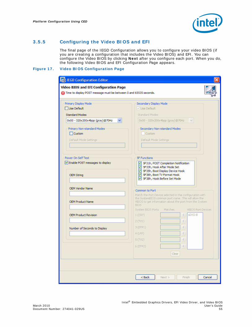
Intel® Embedded Graphics Drivers, EFI Video Driver, and Video BIOSMarch 2010 User’s GuideDocument Number: 274041-029US 55
Platform Configuration Using CED
3.5.5 Configuring the Video BIOS and EFI
The final page of the IEGD Configuration allows you to configure your video BIOS (if you are creating a configuration that includes the Video BIOS) and EFI. You can configure the Video BIOS by clicking Next after you configure each port. When you do, the following Video BIOS and EFI Configuration Page appears.
Figure 17. Video BIOS Configuration Page
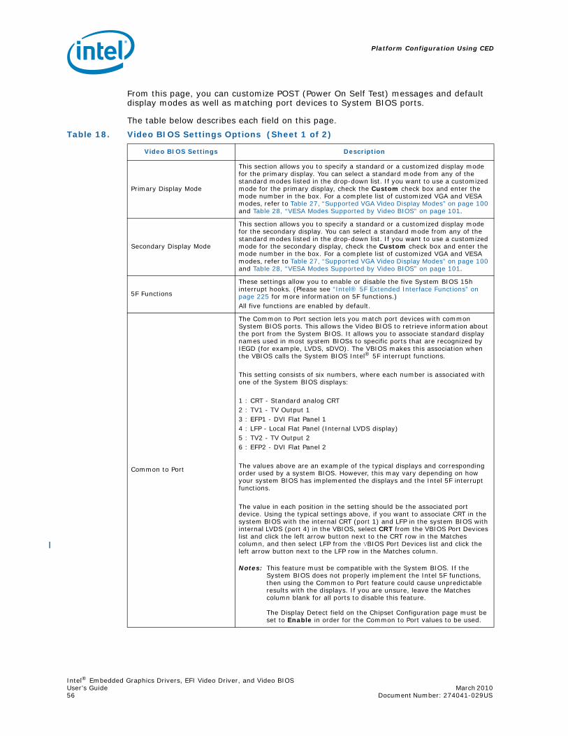
Platform Configuration Using CED
Intel® Embedded Graphics Drivers, EFI Video Driver, and Video BIOSUser’s Guide March 2010 56 Document Number: 274041-029US
From this page, you can customize POST (Power On Self Test) messages and default display modes as well as matching port devices to System BIOS ports.
The table below describes each field on this page.
Table 18. Video BIOS Settings Options (Sheet 1 of 2)
Video BIOS Settings Description
Primary Display Mode
This section allows you to specify a standard or a customized display mode for the primary display. You can select a standard mode from any of the standard modes listed in the drop-down list. If you want to use a customized mode for the primary display, check the Custom check box and enter the mode number in the box. For a complete list of customized VGA and VESA modes, refer to Table 27, “Supported VGA Video Display Modes” on page 100 and Table 28, “VESA Modes Supported by Video BIOS” on page 101.
Secondary Display Mode
This section allows you to specify a standard or a customized display mode for the secondary display. You can select a standard mode from any of the standard modes listed in the drop-down list. If you want to use a customized mode for the secondary display, check the Custom check box and enter the mode number in the box. For a complete list of customized VGA and VESA modes, refer to Table 27, “Supported VGA Video Display Modes” on page 100 and Table 28, “VESA Modes Supported by Video BIOS” on page 101.
5F Functions
These settings allow you to enable or disable the five System BIOS 15h interrupt hooks. (Please see “Intel® 5F Extended Interface Functions” on page 225 for more information on 5F functions.)All five functions are enabled by default.
Common to Port
The Common to Port section lets you match port devices with common System BIOS ports. This allows the Video BIOS to retrieve information about the port from the System BIOS. It allows you to associate standard display names used in most system BIOSs to specific ports that are recognized by IEGD (for example, LVDS, sDVO). The VBIOS makes this association when the VBIOS calls the System BIOS Intel® 5F interrupt functions.
This setting consists of six numbers, where each number is associated with one of the System BIOS displays:
1 : CRT - Standard analog CRT2 : TV1 - TV Output 13 : EFP1 - DVI Flat Panel 14 : LFP - Local Flat Panel (Internal LVDS display)5 : TV2 - TV Output 26 : EFP2 - DVI Flat Panel 2
The values above are an example of the typical displays and corresponding order used by a system BIOS. However, this may vary depending on how your system BIOS has implemented the displays and the Intel 5F interrupt functions.
The value in each position in the setting should be the associated port device. Using the typical settings above, if you want to associate CRT in the system BIOS with the internal CRT (port 1) and LFP in the system BIOS with internal LVDS (port 4) in the VBIOS, select CRT from the VBIOS Port Devices list and click the left arrow button next to the CRT row in the Matches column, and then select LFP from the VBIOS Port Devices list and click the left arrow button next to the LFP row in the Matches column.
Notes: This feature must be compatible with the System BIOS. If the System BIOS does not properly implement the Intel 5F functions, then using the Common to Port feature could cause unpredictable results with the displays. If you are unsure, leave the Matches column blank for all ports to disable this feature.
The Display Detect field on the Chipset Configuration page must be set to Enable in order for the Common to Port values to be used.

Intel® Embedded Graphics Drivers, EFI Video Driver, and Video BIOSMarch 2010 User’s GuideDocument Number: 274041-029US 57
Platform Configuration Using CED
3.6 Creating a New Package
A package consists of one or more configurations and is used to create an installation that works for multiple operating systems and chipset platforms and displays.
To create a new package, click the New Package link at the top of the main CED window. The IEGD Package Page appears.
Enable POST messages to display
To enable Power On Self Test (POST) messages to display during the power on sequence, check this box. If left unchecked (i.e., cleared), the POST messages do not display.
OEM String Enter a string of up to 100 characters. This string appears on the display when the Video BIOS starts up. The default is a blank string.
OEM Vendor NameEnter a string of up to 80 characters that identifies the OEM Vendor. This string appears on the display when the Video BIOS starts up. The default is a blank string.
OEM Product NameEnter a string of up to 80 characters that identifies the OEM Product Revision. This string appears on the display when the Video BIOS starts up. The default is a blank string.
OEM Product RevisionEnter a string of up to 80 characters that identifies the OEM Product Revision. This string appears on the display when the Video BIOS starts up. The default is a blank string.
Number of Seconds to Display Enter the number of seconds to display the above information. The default is 1.
Table 18. Video BIOS Settings Options (Sheet 2 of 2)
Video BIOS Settings Description
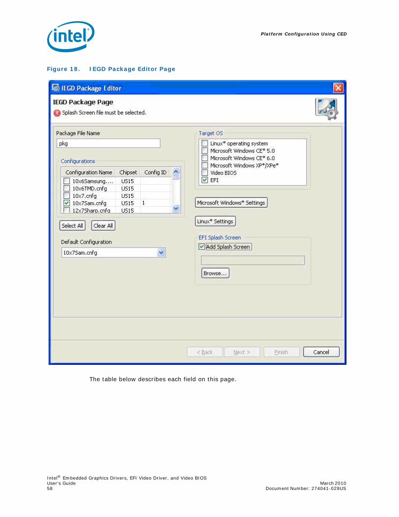
Platform Configuration Using CED
Intel® Embedded Graphics Drivers, EFI Video Driver, and Video BIOSUser’s Guide March 2010 58 Document Number: 274041-029US
The table below describes each field on this page.
Figure 18. IEGD Package Editor Page
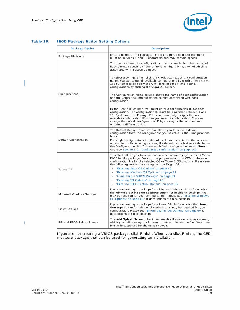
Intel® Embedded Graphics Drivers, EFI Video Driver, and Video BIOSMarch 2010 User’s GuideDocument Number: 274041-029US 59
Platform Configuration Using CED
If you are not creating a VBIOS package, click Finish. When you click Finish, the CED creates a package that can be used for generating an installation.
Table 19. IEGD Package Editor Setting Options
Package Option Description
Package File Name Enter a name for the package. This is a required field and the name must be between 1 and 50 characters and may contain spaces.
Configurations
This blocks shows the configurations that are available to be packaged. Each package consists of one or more configurations, each of which is associated with a specific chipset.
To select a configuration, click the check box next to the configuration name. You can select all available configurations by clicking the Select All button located below the Configurations block and clear all configurations by clicking the Clear All button.
The Configuration Name column shows the name of each configuration and the Chipset column shows the chipset associated with each configuration.
In the Config ID column, you must enter a configuration ID for each configuration. The configuration ID must be a number between 1 and 15. By default, the Package Editor automatically assigns the next available configuration ID when you select a configuration. You can change the default configuration ID by clicking in the edit box and entering a different value.
Default Configuration
The Default Configuration list box allows you to select a default configuration from the configurations you selected in the Configurations block. For single configurations the default is the one selected in the previous option. For multiple configurations, the default is the first one selected in the Configurations list. To have no default configuration, select None. See also Section 5.2, “Configuration Information” on page 103.
Target OS
This block allows you to select one or more operating systems and Video BIOS for the package. For each target you select, the CED produces a configuration file for the selected OS or Video BIOS platform. Please see the following section for settings on the Target OS:• “Entering Linux OS Options” on page 60• “Entering Windows OS Options” on page 62• “Generating a VBIOS Package” on page 63• “Entering EFI Options” on page 63• “Entering EPOG Feature Options” on page 65
Microsoft Windows Settings
If you are creating a package for a Microsoft Windows* platform, click the Microsoft Windows Settings button for additional settings that may be required for your configuration. Please see “Entering Windows OS Options” on page 62 for descriptions of these settings.
Linux Settings
If you are creating a package for a Linux OS platform, click the Linux Settings button for additional settings that may be required for your configuration. Please see “Entering Linux OS Options” on page 60 for descriptions of these settings.
EFI and EPOG Splash ScreenThe Add Splash Screen check box enables the use of a splash screen, which you define using the Browse... button to locate the file. Only .bmp format is supported for the splash screen.
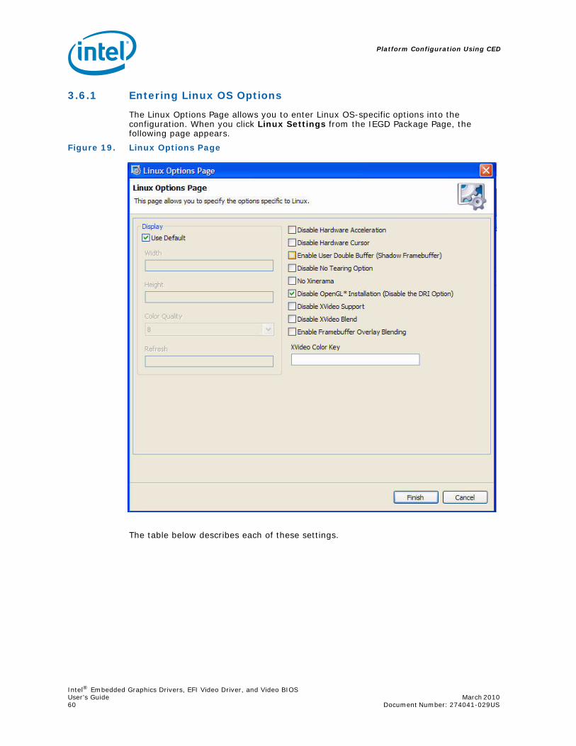
Platform Configuration Using CED
Intel® Embedded Graphics Drivers, EFI Video Driver, and Video BIOSUser’s Guide March 2010 60 Document Number: 274041-029US
3.6.1 Entering Linux OS Options
The Linux Options Page allows you to enter Linux OS-specific options into the configuration. When you click Linux Settings from the IEGD Package Page, the following page appears.
The table below describes each of these settings.
Figure 19. Linux Options Page

Intel® Embedded Graphics Drivers, EFI Video Driver, and Video BIOSMarch 2010 User’s GuideDocument Number: 274041-029US 61
Platform Configuration Using CED
Table 20. Linux OS Settings Options
Linux OS Option Description
Default Display Modes
The Default Display Modes section allows you select the default resolution, color depth, and refresh rate for the configuration. If you do not select a default display mode, the package uses the default display mode for the operating system it is installed on.
Disable Hardware Acceleration Disable or enable hardware 2D acceleration. The default is to enable hardware acceleration, so to disable acceleration, click the check box.
Enable Hardware Cursor Enable the use of the hardware cursor. By default, the hardware cursor is disabled.
Enable Use Double Buffer(Shadow Framebuffer)
Enable double buffering on the framebuffer. By default, double buffering is disabled. To enable it, click the check box.
Disable No Tearing OptionDisable No Tearing. By default, the No Tearing is enabled. Disabling this option results in a performance penalty as the driver is forced to synchronize page flips to the vertical blanking signal.
No Xinerama
Xinerama support. Xinerama is an extension to the X Window System which allows applications and window managers to use the two (or more) physical displays as one large virtual display. By default, Xinerama is enabled. To disable it, click the check box.
Disable OpenGL* Installation (Disable the DRI Option)
OpenGL* (Disable the Direct Rendering Infrastructure (DRI) Option). DRI allows the client to directly write to DMA buffers that are used by the graphics hardware.To disable OpenGL, check the box. The option “DRI” “0” will be set for every available display. This will turn off direct rendering and disable hardware accelerated OpenGL.By default, OpenGL is enabled. No “DRI” line(s) are placed in the configuration file. The driver will intelligently determine if DRI can be supported and will enable it if possible.
Note: If you manually edit the configuration file and set option “DRI” “1” on more than one display, deadlock will occur and OpenGL will fail. If you are unsure of which setting to use, just leave the box unchecked (i.e., cleared) and do not edit the DRI option in the configuration file and the driver will handle it automatically. This feature can be used if you want to test your applications with and without hardware accelerated OpenGL.
For a list of related application programming interfaces, see “2D/3D API Support” on page 235.
Disable XVideo Support
Disable XVideo support. In a dual independent head configuration, either the first display or the second display supports XVideo. Both displays can not support XVideo simultaneously. The default is XVideo support is enabled.
Disable XVideo Blend
Disable XVideo support using the 3D blend manager. This provides XVideo support in configurations that cannot be supported with overlay. For example, this is supported on both displays in a dual independent head setup. It is also supported when the display is rotated or flipped. Color key is only supported if ShadowFB is enabled and the VideoKey is defined. The default is XVideoBlend support is enabled.
Enable Frame Buffer Overlay Blending
When checked, this enables overlay blending with the framebuffer on both display outputs (if in VEXT mode on Windows CE) on US15W and when display mode resolution is 32-bit XRGB.
XVideo Color Key
This sets the color key for XVideo and XVideoBlend. This value is either a 24-bit value or a 16-bit value, depending on the pixel depth of the screen. The color key is always enabled for XVideo, even when it is not defined. The color key is always disabled for XVideoBlend unless both this option is defined and the ShadowFB option is enabled. The default color key for XVideo is 0x0000ff00. For XVideo Blend, the color key is disabled by default.
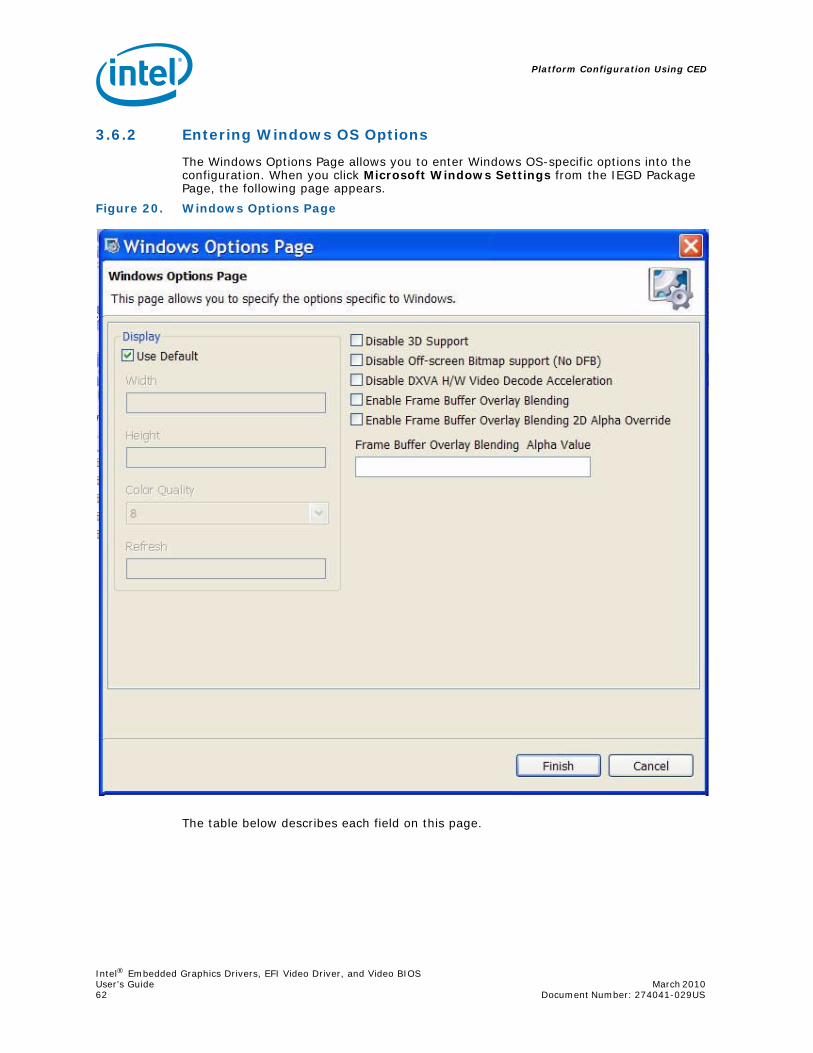
Platform Configuration Using CED
Intel® Embedded Graphics Drivers, EFI Video Driver, and Video BIOSUser’s Guide March 2010 62 Document Number: 274041-029US
3.6.2 Entering Windows OS Options
The Windows Options Page allows you to enter Windows OS-specific options into the configuration. When you click Microsoft Windows Settings from the IEGD Package Page, the following page appears.
The table below describes each field on this page.
Figure 20. Windows Options Page

Intel® Embedded Graphics Drivers, EFI Video Driver, and Video BIOSMarch 2010 User’s GuideDocument Number: 274041-029US 63
Platform Configuration Using CED
3.6.3 Generating a VBIOS Package
If you are creating a package for a VBIOS installation, click Next. The CED displays the VBIOS Generation page.
To generate a VBIOS, click the Generate VBIOS check box and select the configurations to include. After selecting the chipset and the configurations, click Finish. The CED generates a package that includes both the OROM and the TSR for the chipsets and the configurations you selected.
3.6.4 Entering EFI Options
If you are creating a package for a EFI installation, click Next. The CED displays the EFI Generation page.
Table 21. Windows OS Setting Options
Windows OS Option Description
DisplayThe Display section allows you to use the default settings by checking the Use Default check box or to select the default width, height, color quality, and refresh rate for the configuration.
Disable 3D Support Specifies whether to enable D3D. The default is to enable 3D support (not checked).
Disable Off-screen Bitmap support (No DFB)
This option turns OFF the driver capabilities to create and use offscreen bitmaps that are used to improve GDI and DirectDraw* performance in the driver. When this option is ON, you may see some GDI and DirectDraw performance degradation. The drv functions below will be affected when this option is turned on. • DrvCreateDeviceBitmap• DrvDeleteDeviceBitmap• DrvDeriveSurface
Disable DXVA H/W Video Decode Acceleration
This option is enabled by default in IEGD, however, by selecting this option, you can disable DXVA hardware video decode acceleration.
Enable Frame Buffer Overlay Blending
When checked, this option enables overlay blending with the framebuffer on both display outputs (if in VEXT mode) on US15W and when display mode resolution is 32-bit XRGB.
Enable Frame Buffer Overlay Blending 2D Alpha Override
This option applies only to Windows XP and US15W. When checked, it enables an override to the frame buffer overlay blending 2D alpha.
Notes: Checking the Frame Buffer Overlay Blending option and running a 3D alpha blending application on overlay [non full screen mode] causes the black icons on the desktop to appear. This is expected behavior as the operating system sets the 2D alpha values. To overcome this behavior, choose Enable Frame Buffer Overlay Blending 2D Alpha Override option and then enter the alpha value. This alpha override will cause performance impact when a lot of 2D blitting operations take place.
This option applies only to Windows XP and US15W. When checked, it enables an override to the frame buffer overlay blending 2D alpha.
Frame Buffer Overlay Blending Alpha Value The valid range is from 0x00 to 0xFF.

Platform Configuration Using CED
Intel® Embedded Graphics Drivers, EFI Video Driver, and Video BIOSUser’s Guide March 2010 64 Document Number: 274041-029US
To generate an EFI configuration:
1. In the Fastboot and/or General modes sections, click the Generate EFI checkbox.
2. Select the chipset and configuration(s) to include.
3. Click Finish. The CED generates a package that includes the EFI driver for the modes, chipsets and the configurations you selected.
Figure 21. EFI Generation Page

Intel® Embedded Graphics Drivers, EFI Video Driver, and Video BIOSMarch 2010 User’s GuideDocument Number: 274041-029US 65
Platform Configuration Using CED
3.6.5 Using the Generated EFI Configuration
Use IEGD CED to configure and build an EFI video driver for your platform, as described in Section 3.6.4 and then follow the instructions below to install the driver.
1. After building the EFI driver, copy the appropriate module to your working directory where you keep your Aptio MMTOOL and EFI BIOS that needs to be updated. The file is typically called IEGD.DXE and is found in the IEGD ZIP file in the installations folder under EFI.
2. Make a working copy of your EFI BIOS image. For example, copy CBCHAxxx.ROM to CBCHAxxx_IEGD_EFI.ROM where xxx = the release version of Standard BIOS
OR
Copy CBFBAxxx.ROM to CBFBAxxx_IEGD_EFI.ROM where xxx = the release version of Fast Boot BIOS)
3. Start the MMTOOL in GUI mode.
4. Load the EFI BIOS image using the Load Image button.After it loads you will be presented with a list of existing modules.
5. Select CBCHAxxx_IEGD_EFI.ROM or CBFBAxxx_IEGD_EFI.ROM (from step 2.)
6. If it exists, delete any legacy VBIOS by highlighting the old video solution, select the DELETE tab at the top, and then press the DELETE button.
Note: The EFI Fast Boot images typically do NOT contain a video module.
For example, for CBCHAxxx.ROM you will see a CSMVIDEO module. This is the Compatibility Software Module for a legacy VBIOS.
7. If it exists, delete any old versions of the IEGD EFI Fast Boot Video Driver. Look for an unnamed module with a GUID that starts with “2B13E5F0-” or with a module name that includes “IEGD”. If it exists, select the DELETE tab, highlight the module and then click the DELETE button.
8. Insert the new video module by clicking on the INSERT tab, specifying the module file name, and then clicking the INSERT button. You may browse to locate the file, for example, iegd.dxe.)
9. Save image by clicking the Save Image button and then close the dialog box.
10. Flash the image into your flash chip and install it on the board. You can either use the hardware flash programmer or the Aptio AFUDOS tool for this purpose.
3.6.6 Entering EPOG Feature Options
If you are creating a package for an EPOG feature installation, follow the steps below.
1. From the Target OS section, select EPOG.
2. If you want to use a splash screen, select the Add Splash Screen check box and then browse to the .bmp file you want to use.
3. Click Finish. The CED generates a package that includes the embedded pre-OS graphics feature for the modes, chipsets, and configurations you selected.
Platform Configuration Using CED
Intel® Embedded Graphics Drivers, EFI Video Driver, and Video BIOSUser’s Guide March 2010 66 Document Number: 274041-029US
3.6.7 Using the Generated Embedded Pre-OS Graphics Feature Configuration
Use IEGD CED to configure and build a driver with the embedded pre-OS graphics feature, as described in “Entering EPOG Feature Options” and then follow the instructions below to install the driver.
1. After generating the driver with the embedded pre-OS graphics feature, untar the tar file generated by the CED.
2. Copy the file libepog.a and paste it in the lib/elf directory in BLDK.
3. Follow the BLDK build procedure with graphics enabled. (BLDK can be obtained at the Intel Validation Internet portal https://platformsw.intel.com/index.aspx)
3.7 Generating an Installation
After you have created a package, you can generate an installation for the package by following this procedure.
1. Select a package from the Package folder located on the left pane of the CED main window.
2. Click Generate Installation. While the installation is building, the CED displays a progress bar. When the installation is complete, the CED places the output in the Installation folder on the left pane of the CED window.
For each OS and VBIOS platform specified in the package, the CED generates a folder in the ...\workspace\installation folder under the current folder. For example, if you select a package that contains configurations for all supported operating systems and the VBIOS, the CED generates the following folders:...\workspace\installation\<package name_installation>\IEGD_10_3_1_Linux...\workspace\installation\<package name_installation>\IEGD_10_3_1_WINDOWS...\workspace\installation\<package name_installation>\IEGD_10_3_1_WINCE50...\workspace\installation\<package name_installation>\IEGD_10_3_1_WINCE60...\workspace\installation\<package name_installation>\IEGD_10_3_1_VBIOS...\workspace\installation\<package name_installation>\IEGD_10_3_1_EFI
These folders contain all the subfolders required for the installation onto the target systems. To complete the installations on the target systems, refer to the following sections:
• “Installing and Configuring Linux* OS Drivers” on page 149
• “Configuring and Installing Microsoft Windows Drivers” on page 103
• “Configuring and Building the IEGD for Microsoft Windows CE* Systems” on page 119
• “Entering Linux OS Options” on page 60
3.8 Configuring the System BIOS for Use with the IEGD
Some aspects of configuring the Intel® Embedded Graphics Drivers are common across the Video BIOS (VBIOS), EFI, and the drivers for the supported operating systems. The following sections provide an overview for configuring both the VBIOS and the Intel
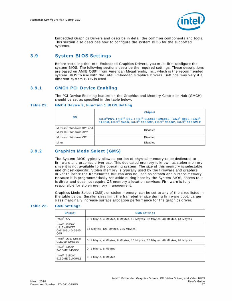
Intel® Embedded Graphics Drivers, EFI Video Driver, and Video BIOSMarch 2010 User’s GuideDocument Number: 274041-029US 67
Platform Configuration Using CED
Embedded Graphics Drivers and describe in detail the common components and tools. This section also describes how to configure the system BIOS for the supported systems.
3.9 System BIOS Settings
Before installing the Intel Embedded Graphics Drivers, you must first configure the system BIOS. The following sections describe the required settings. These descriptions are based on AMIBIOS8* from American Megatrends, Inc., which is the recommended system BIOS to use with the Intel Embedded Graphics Drivers. Settings may vary if a different system BIOS is used.
3.9.1 GMCH PCI Device Enabling
The PCI Device Enabling feature on the Graphics and Memory Controller Hub (GMCH) should be set as specified in the table below.
3.9.2 Graphics Mode Select (GMS)
The System BIOS typically allows a portion of physical memory to be dedicated to firmware and graphics driver use. This dedicated memory is known as stolen memory since it is not available to the operating system. The size of this memory is selectable and chipset-specific. Stolen memory is typically used by the firmware and graphics driver to locate the framebuffer, but can also be used as scratch and surface memory. Because it is programmatically set aside during boot by the System BIOS, access to it is direct and does not require OS memory allocation services. Firmware is fully responsible for stolen memory management.
Graphics Mode Select (GMS), or stolen memory, can be set to any of the sizes listed in the table below. Smaller sizes limit the framebuffer size during firmware boot. Larger sizes marginally increase surface allocation performance for the graphics driver.
Table 22. GMCH Device 2, Function 1 BIOS Setting
OS
Chipset
Intel®PNV, Intel® Q35, Intel® GLE960/GME965, Intel® Q965, Intel® 945GM, Intel® 945G, Intel® 915GME, Intel® 915GV, Intel® 910GMLE
Microsoft Windows XP* andMicrosoft Windows XPe*
Disabled
Microsoft Windows CE* Disabled
Linux Disabled
Table 23. GMS Settings
Chipset GMS Settings
Intel®PNV 0, 1 Mbyte, 4 Mbytes, 8 Mbytes, 16 Mbytes, 32 Mbytes, 48 Mbytes, 64 Mbytes
Intel®US15W/US15WP/WPT, GM45/GL40/GS45, Q45
64 Mbytes, 128 Mbytes, 256 Mbytes
Intel® Q35, Q965/GLE960/GME965 0, 1 Mbyte, 4 Mbytes, 8 Mbytes, 16 Mbytes, 32 Mbytes, 48 Mbytes, 64 Mbytes
Intel® 945G/945GME/945GSE 0, 1 Mbyte, 8 Mbytes
Intel® 915GV/915GME/910GMLE 0, 1 Mbyte, 8 Mbytes

Platform Configuration Using CED
Intel® Embedded Graphics Drivers, EFI Video Driver, and Video BIOSUser’s Guide March 2010 68 Document Number: 274041-029US
3.9.3 AGP (Accelerated Graphics Port) Aperture Size
The AGP Aperture size controls the total amount of graphics memory that can be mapped in the AGP Aperture. This value can be set from 64 Mbytes up to 256 Mbytes, depending on the chipset. Refer to specific chipset details for information on the valid range.
3.10 VBIOS and Driver Configuration
The Intel Embedded Graphics Suite allows user configuration of both the VBIOS and graphics driver as well as programming of Detailed Timing Descriptors (DTDs) for EDID-less panels for both the VBIOS and graphics driver. This is accomplished using CED, which offers several ways to input DTDs, each associated with a potential target panel and display mode for the system. CED generates DTD and configuration settings used by the IEGD VBIOS, Linux, and/or Windows drivers.
The following example is for a 945GME system setup with just an internal LVDS and sample timing parameters for illustration purposes only. You can use this example to set up DTD timings that are specific to your non-standard panels and then activate the panels using a custom mode.
To create a configuration and configure the LVDS options:
1. Create a custom DTD as described in Section 3.4, “Creating a New Customized DTD” on page 32.
1. From the CED main screen, select New Configuration.
2. Enter a name for the configuration in the text box provided, for example, LVDS_test.
3. Select the platform chipset. This example uses the 945GME chipset.
4. In the list of available ports, select LVDS and then click Next.
5. On the LVDS Configuration Page, clear the checkboxes for Use EDID Display if available and Use driver built-in standard timings.
6. Select the checkbox for Use user-defined DTDs.
7. In the Encoder Configuration section, select Internal LVDS.
8. In the Custom Display Timing Descriptors (DTDs) list, select the DTD you created in Section 3.4, “Creating a New Customized DTD” on page 32 for example, test_LVDS.The screen will be similar to the example below.
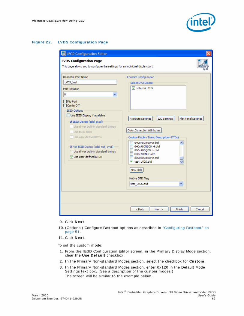
Intel® Embedded Graphics Drivers, EFI Video Driver, and Video BIOSMarch 2010 User’s GuideDocument Number: 274041-029US 69
Platform Configuration Using CED
9. Click Next.
10. (Optional) Configure Fastboot options as described in “Configuring Fastboot” on page 51.
11. Click Next.
To set the custom mode:
1. From the IEGD Configuration Editor screen, in the Primary Display Mode section, clear the Use Default checkbox.
2. In the Primary Non-standard Modes section, select the checkbox for Custom.
3. In the Primary Non-standard Modes section, enter 0x120 in the Default Mode Settings text box. (See a description of the custom modes.)The screen will be similar to the example below.
Figure 22. LVDS Configuration Page

Platform Configuration Using CED
Intel® Embedded Graphics Drivers, EFI Video Driver, and Video BIOSUser’s Guide March 2010 70 Document Number: 274041-029US
Custom Modes
The custom modes begin with 0x120 (0x121 and 0x122 are the same modes in different pixel formats). If there was a second custom mode entered it would begin with 0x123 to 0x125.
From the above DTD 200x200 example, this is what the custom modes represent:
0x120 200x200@8bpp
0x121 200x200@16bpp
0x122 200x200@32bpp
Figure 23. IEGD Configuration Editor Page
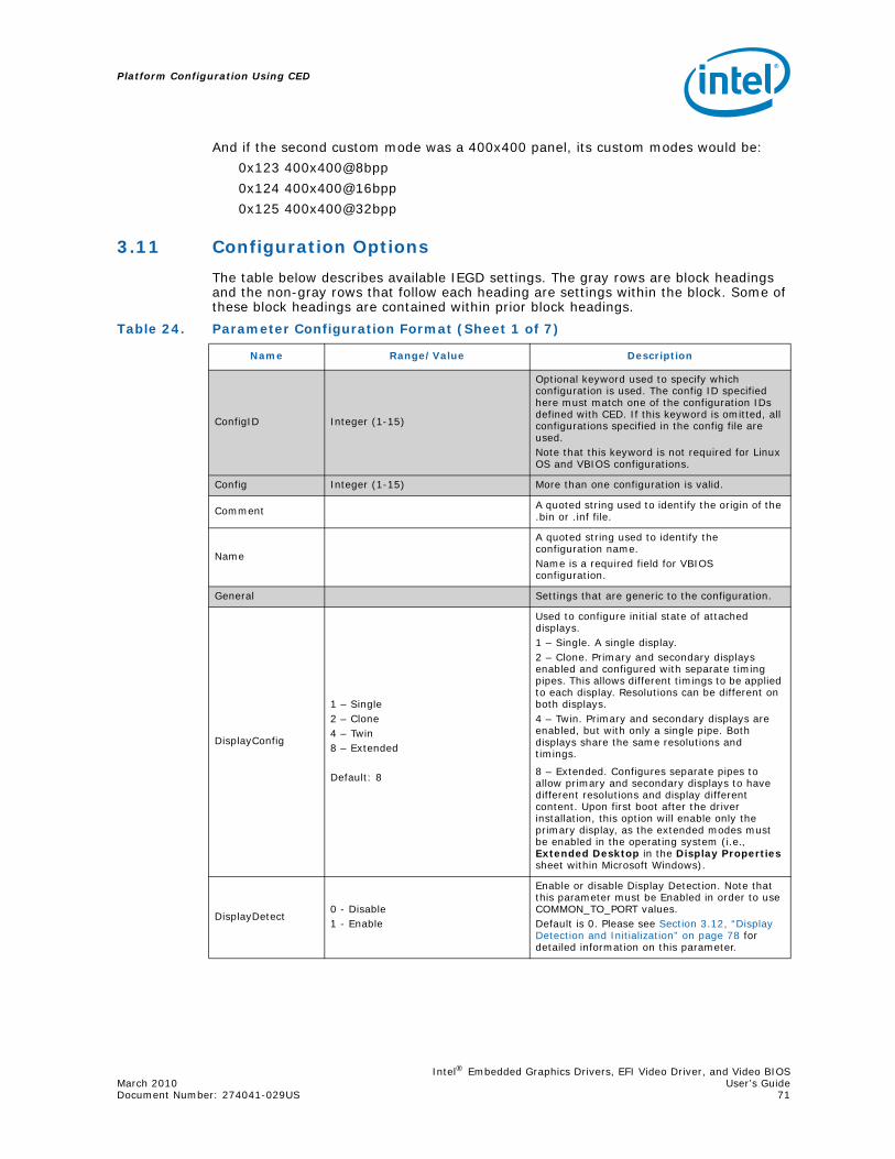
Intel® Embedded Graphics Drivers, EFI Video Driver, and Video BIOSMarch 2010 User’s GuideDocument Number: 274041-029US 71
Platform Configuration Using CED
And if the second custom mode was a 400x400 panel, its custom modes would be:
0x123 400x400@8bpp
0x124 400x400@16bpp
0x125 400x400@32bpp
3.11 Configuration Options
The table below describes available IEGD settings. The gray rows are block headings and the non-gray rows that follow each heading are settings within the block. Some of these block headings are contained within prior block headings.
Table 24. Parameter Configuration Format (Sheet 1 of 7)
Name Range/Value Description
ConfigID Integer (1-15)
Optional keyword used to specify which configuration is used. The config ID specified here must match one of the configuration IDs defined with CED. If this keyword is omitted, all configurations specified in the config file are used. Note that this keyword is not required for Linux OS and VBIOS configurations.
Config Integer (1-15) More than one configuration is valid.
Comment A quoted string used to identify the origin of the .bin or .inf file.
Name
A quoted string used to identify the configuration name. Name is a required field for VBIOS configuration.
General Settings that are generic to the configuration.
DisplayConfig
1 – Single2 – Clone4 – Twin8 – Extended
Default: 8
Used to configure initial state of attached displays.1 – Single. A single display.2 – Clone. Primary and secondary displays enabled and configured with separate timing pipes. This allows different timings to be applied to each display. Resolutions can be different on both displays.4 – Twin. Primary and secondary displays are enabled, but with only a single pipe. Both displays share the same resolutions and timings.
8 – Extended. Configures separate pipes to allow primary and secondary displays to have different resolutions and display different content. Upon first boot after the driver installation, this option will enable only the primary display, as the extended modes must be enabled in the operating system (i.e., Extended Desktop in the Display Properties sheet within Microsoft Windows).
DisplayDetect0 - Disable1 - Enable
Enable or disable Display Detection. Note that this parameter must be Enabled in order to use COMMON_TO_PORT values.Default is 0. Please see Section 3.12, “Display Detection and Initialization” on page 78 for detailed information on this parameter.

Platform Configuration Using CED
Intel® Embedded Graphics Drivers, EFI Video Driver, and Video BIOSUser’s Guide March 2010 72 Document Number: 274041-029US
PortOrder
PortOrder must be specified as a quoted string containing five digits. The valid values are:
1 - Integrated TV Encoder (mobile chipsets only)2 - sDVO B port3 - sDVO C port4 - Integrated LVDS port (mobile chipsets only)5 - Analog CRT port6 - Internal HDMIDefault: 0 for all keys
Search order for detecting attached displays for the Display Detection feature. When Display Detection is enabled, the PortOrder determines which display is primary and which display is secondary.The port search order can be specified to ensure the port device (sDVO device) is found, based on the system integrator’s routing choices. Default ordering is chosen by specifying zeros in the PortOrder keys.Default ordering is chipset specific; see Table 56, “Default Search Order” on page 222.Please see Section 3.12, “Display Detection and Initialization” on page 78 for more information on using PortOrder in combination with the Display Detect feature.
CloneWidthCloneHeight
Typical sizes:clonewidth – 800, cloneheight - 600clonewidth – 1024, cloneheight - 768clonewidth – 1280, cloneheight - 768clonewidth – 1400, cloneheight – 1050
Width and height for a cloned display.
CloneRefresh = 60
Typical refresh rates (expressed in Hz):
60 Hz, 75 Hz, 85 Hz
Refresh rate for a cloned display.
OverlayOff0 - Overlay on (default)1 - Overlay off
This parameter allows you disable Overlay support, which is enabled by default. Note: This parameter is only for Microsoft Windows* and Microsoft Windows CE. The Linux* OS configuration for the xorg.conf provides a standard option that performs the same function.
FbBlendOvl0 - Off (Default)1 - On
When checked, this enables overlay blending with the framebuffer on both display outputs (if in VEXT mode on Windows CE) on US15W and when display mode resolution is 32-bit XRGB.
No_DFB0 - Off (Default)1 - On
This parameter enables the IEGD to pass the DIB call back to the OS. This is required in certain circumstances to improve performance.
vbios
This block contains settings for the Video BIOS. Note that you only need to specify the parameters you are actually using. You do not need to specify all the parameters in this block. If you omit any parameters, the vbios uses the default values.
COMMON_TO_PORT 6 digit value
Maps the ports from the system BIOS to a port number used by the graphics hardware. Please see Section 4.3.2, “Configuring the Video BIOS” on page 93 for more information on this parameter. Note that the displaydetect parameter must be set to Enabled in order for the COMMON_TO_PORT values to be used.The default is all zeroes: 000000
Table 24. Parameter Configuration Format (Sheet 2 of 7)
Name Range/Value Description

Intel® Embedded Graphics Drivers, EFI Video Driver, and Video BIOSMarch 2010 User’s GuideDocument Number: 274041-029US 73
Platform Configuration Using CED
post_display_msg
0 - disablegreater than 0 - enable and display POST message for the specified number of seconds
Enables or disables the POST (Power On Self Test) message. When you specify a value greater than 0, the message is displayed for the specified number of seconds. For example:
post_display_msg = 5
This enables the POST message and displays it for approximately 5 seconds. The maximum value that can be entered here is 65535.
The default is 1, enable and display the POST message for approximately 1 second.
oem_string double-quoted string
This string appears on the display when the post_display_msg is enabled and the VBIOS starts up. The maximum string length is 100 characters.The default is " " (two double quotes with a single space in between).
oem_vendor double-quoted string
This string appears on the display when the post_display_msg is enabled and the VBIOS starts up. The maximum string length is 80 characters.The default is " " (two double quotes with a single space in between).
oem_product_name double-quoted string
This string appears on the display when the post_display_msg is enabled and the VBIOS starts up. The maximum string length is 80 characters.The default is " " (two double quotes with a single space in between).
oem_product_rev double-quoted string
This string appears on the display when the post_display_msg is enabled and the VBIOS starts up. The maximum string length is 80 characters.The default is " " (two double quotes with a single space in between).
Table 24. Parameter Configuration Format (Sheet 3 of 7)
Name Range/Value Description

Platform Configuration Using CED
Intel® Embedded Graphics Drivers, EFI Video Driver, and Video BIOSUser’s Guide March 2010 74 Document Number: 274041-029US
int15 5 digits
This parameter allows you to enable or disable the five System BIOS 15h interrupt hooks. The value must be 5 digits in length. Each digit is associated with one of the five System BIOS interrupt 15h hooks as shown below (left to right)1 - 5F31h, POST Completion Notification Hook2 - 5F33h, Hook After Mode Set3 - 5F35h, Boot Display Device Hook4 - 5F36h, Boot TV Format Hook5 - 5F38h, Hook Before Set Mode
(Please see Appendix C for more information on 5F functions.)
The value of each digit must be a 0 or a 1 as follows:0 - disable a System BIOS 15h hook1 - enable a System BIOS 15h hook
For example,int15 = 11001
Enables 5F31h, 5F33h, and 5F38h hooks only. The 5F35h and 5F36h hooks are disabled.
The default is 11111, enable all five hooks.
port
1 - Integrated TV Encoder (mobile chipsets only)2 -sDVO B port3 - sDVO C port4 - Integrated LVDS port (mobile chipsets only)5 - Analog CRT port
Used to define port specific settings.
rotation
Windows* OS Range:0x0 or 0 – 0 degrees0x5A or 90 – 90 degrees0xB4 or 180 – 180 degrees0x10E or 270 – 270 degrees
Linux OS Range:0 – 0 degrees90 – 90 degrees180 – 180 degrees270 – 270 degrees
Default: 0
Rotation of the display.
Note: For Windows CE Static rotation, setting the width and height to the rotated values is no longer required with the improvements beginning in v10.1.
flip
Windows OS:0x0 or 0 – turn off horizontal flip0x1 or 1 – turn on horizontal flipDefault: 0
Linux OS Boolean:on - horizontal flipoff - no horizontal flipDefault: off
Flip of the display.
Table 24. Parameter Configuration Format (Sheet 4 of 7)
Name Range/Value Description

Intel® Embedded Graphics Drivers, EFI Video Driver, and Video BIOSMarch 2010 User’s GuideDocument Number: 274041-029US 75
Platform Configuration Using CED
centeroff
Default: 0 – disabled, allow centering and add compatibility modes1 – enabled, no centering, no added compatibility modes
When this option is enabled it DISABLES centering. Also, depending on the combination of “edid” + “user-dtd” + connected hardware, IEGD will add missing compatibility modes (6x4, 8x6, 10x7& 12x10) via centering. Use this option to disable this feature.
edid0 – Do not read EDID from panel/CRT1 – Attempt to extract EDID timing data from panel/CRT
If VBIOS/driver reads EDID from panel/CRT.
edid_availedid_not_avail
Range [16 bits]Valid values (specified in hex):
bit 0------------0 - Do not use driver built-in
standard timings1 - Use driver built-in standard
timingsbit 1 (not applicable to
edid_not_avail)------------0 - Do not use EDID block1 - Use EDID block and filter
modesbit 2------------0 - Do not use user-defined DTDs1 - Use user-defined DTDsbit3 - bit15------------Reserved for future use.
These two parameters are used to control the available timings for any display. edid_avail is used when EDID values are read from the display. If an attempt to read EDID from the display fails or the edid parameter is set to 0, then the driver uses the edid_not_avail flags. The value for both parameters must be specified as a hex value.
Defaults:edid_avail: 3 (hex). Bit 0 = 1, Bit 1 = 1, Bit 2 =0 (Use driver built-in standard timings and EDID block and filter modes.) edid_not_avail: 1 (hex). Bit 0 = 1, Bit 1 = 0, Bit 2 = 0. (Use driver-built-in standard timings.)
Please see Section 3.13, “Advanced EDID Configuration” on page 80 for detailed information.
multidvo
0 – Do not attempt to detect a second decoder of same type1 – After detect of a decoder, continue to attempt detection of same type of decoder until fail
If VBIOS/driver detects a second decoder of same type.This value is hard-coded to “1” for Windows configuration and will ignore this setting.
dvo sDVO device information.
i2cpin <0-6> The GPIO pin pair used on the I2C bus to read and write to sDVO device registers.
ddcpin <0-6> The GPIO pin pair used as DDC bus to read panel EDID data.
i2cdab <0x00-0xff>
I2C device address for reading and writing device registers.The device address should be in 8-bit format with the 7-bit slave address assigned to its bits 7:1 and bit 0 set to 0.
ddcdab <0x00-0xff> I2C device address for reading EDID data from display through the DDC bus.
i2cspeed [10-400]. Units in KHz Speed of I2C bus for sDVO device.
ddcspeed [10-400]. Units in KHz Speed of I2C bus for EDID device.
fpinfo Panel-specific information.
Table 24. Parameter Configuration Format (Sheet 5 of 7)
Name Range/Value Description

Platform Configuration Using CED
Intel® Embedded Graphics Drivers, EFI Video Driver, and Video BIOSUser’s Guide March 2010 76 Document Number: 274041-029US
bkltmethod
Range [0-3]0 – no backlight1 – Port Driver2 – GMCH3 – ICH
Note: The only supported parameter for internal LVDS is 1 – Port Driver
Instructs which backlight method is required for the panel attached to the given port.If zero is supplied, or the key is not present, then no backlight control is provided.
bkltt1
Range [0 -0xfff].Units of 1ms => the limit specified in your hardware specifications. For example, the maximum for the CH7307 is 409 ms.
(T1) Time delay between VDD active, and sDVO clock/data active. Zero indicates no delay required.
bkltt2 (T2) Time delay between sDVO clock/data active and Backlight enable.
bkltt3 (T3) Time delay between Backlight disable and sDVO clock/data inactive.
bkltt4 (T4) Time delay between sDVO clock/data inactive and VDD inactive.
bkltt5 (T5) Minimum delay between VDD inactive, and active.
gpiopinvee Valid ICH GPIO pin, 0 indexed
For example:gpiopinvdd = 3gpiopinvee = 5gpiopinenable = 1
GPIO connection for panel power.
gpiopinvdd GPIO connection for backlight power on/off sequencing signal.
gpiopinbklt GPIO to enable backlight signal.
UseGMCHClockPin
1 - Flat panel is connected to the clock pin0 - Flat panel is not connected to the clock pin
This entry is needed when GMCH is selected as backlight control method.
UseGMCHDataPin
1 - Flat panel is connected to the data pin0 - Flat panel is not connected to the data pin
This entry is needed when GMCH is selected as backlight control method.
dtd
Denotes a Detailed Timing Descriptor (DTD) block. Settings in this section, except for the flags parameter, correspond to the Detailed Timing Block described in the VESA standard “Extended Display Identification Data Standard”, Version 3, November 13, 1997.
p_clock Range [0-0x7fffffff] Pixel clock value in KHz.
h_active Range 0-4096 [12 bits] Horizontal Active.
v_active Range 0-4096 [12 bits] Vertical Active.
h_sync Range 0-1024 [10 bits] Horizontal Sync Offset.
v_sync Range 0-64 [6 bits] Vertical Sync Offset.
h_syncp Range 0-1024 [10 bits] Horizontal Sync Pulse Offset.
v_syncp Range 0-64 [6 bits] Vertical Sync Pulse Width.
h_blank Range 0-4096 [12 bits] Horizontal Blanking.
v_blank Range 0-4096 [12 bits] Vertical Blanking.
h_border Range 0-256 [8 bits] Horizontal Border. Currently not supported.
v_border Range 0-256 [8 bits] Vertical Border. Currently not supported.
h_size Range 0-4096 [12 bits] Horizontal Size. Currently not supported.
Table 24. Parameter Configuration Format (Sheet 6 of 7)
Name Range/Value Description

Intel® Embedded Graphics Drivers, EFI Video Driver, and Video BIOSMarch 2010 User’s GuideDocument Number: 274041-029US 77
Platform Configuration Using CED
v_size Range0-4096 [12 bits] Vertical size. Currently not supported.
flags
Range [32 bits]Valid values:
bit 31------------0 - Non-interlaced1 - Interlaced
bit 27------------0 - vertical sync polarity active
low1 - vertical sync polarity active
high
bit 26------------0 - horizontal sync polarity active
low1 - horizontal sync polarity active
high
bit 25------------0 - blank sync polarity active high1 - blank sync polarity active low
bit 17------------0 - Normal DTD1 - Panel/display Native DTD
All other bits-----------------
Do not use any other bits; all other bits must be set to 0.
Interlace, Horizontal polarity, Vertical polarity, Sync Configuration, etc. Note that these flags are IEGD specific and do not correspond to VESA 3.0 flags. For example, to set Interlaced with Horizontal Sync Polarity high (bits 31 and 26), then the flags value = 0x84000000. (Binary = 10000100000000000000000000000000)
attr 0-0xFFFF
Attribute values that are specific to the sDVO device for the port. See Appendix B, “Port Driver Attributes” for specific attribute IDs and associated values.
id <Attribute ID> 0 - 232
id = <value>.
Both the Attribute ID and its value should be specified in decimal. For example, to set brightness to 50, you specify
id 0 = 50See Appendix B, “Port Driver Attributes”.
Table 24. Parameter Configuration Format (Sheet 7 of 7)
Name Range/Value Description
Platform Configuration Using CED
Intel® Embedded Graphics Drivers, EFI Video Driver, and Video BIOSUser’s Guide March 2010 78 Document Number: 274041-029US
3.12 Display Detection and Initialization
The Display Detection and Initialization feature, when enabled, automatically detects displays and allocates ports without the need to change any configuration files. This feature is off by default and can be enabled either through CED or by directly editing the iegd.inf file for Microsoft Windows or the xorg.conf file for the Linux OS.
To enable the feature via CED, select the DisplayDetect option on the CED Chipset Configuration page. Please see Section 3.5, “Creating a New Configuration” on page 36 or CED online help for more information.
Alternatively, you can enable the feature in Microsoft Windows by entering the following line in the [iegd_SoftwareDeviceSettings] section of the iegd.inf file:
HKR, All\<ConfigID>\General, DisplayDetect, %REG_DWORD%, 1
where <ConfigID> is the configuration ID (without the angle brackets).
To enable the feature in the Linux OS, enter the following line Option setting in the xorg.conf file:
Option “Config/<ConfigID>/General/DisplayDetect” “1”
When the display detection feature is enabled, ports are allocated only when the display satisfies the following conditions:
1. The port is not in use (that is, it is not already allocated).
2. The display is detected by the port driver.
The first port that passes these conditions is allocated. If condition 2 fails for all ports, then the first port in the PortOrder setting that passes condition 1 is allocated. If the port is not detectable (specifically the internal LVDS or external LVDS using CH7308), the driver assumes the display is connected. Condition number 2. always passes for these displays.
When this feature is disabled, display allocation is done based on PortOrder and no display detection is performed.
3.12.1 Display Detect Operation
This section describes the logic of the Display Detection feature and provides several examples.
1. If Display Detect is disabled, the driver uses the first two ports identified in the PortOrder.
2. If Display Detect is enabled and you are using the 10.3.1 version of the VBIOS, the VBIOS performs the display detection. The driver then checks to see if the VBIOS returns the display allocations and if it does, the driver does not re-execute the display detection steps. If you are not using the v10.3.1 Legacy VBIOS, then the driver performs display discovery as described in the following steps.
3. The number of displays to be detected is based on the DisplayConfig settings in the configuration. If this is set to Single, then only one display is detected. If it is set to any other value, a maximum of two displays will be detected.

Intel® Embedded Graphics Drivers, EFI Video Driver, and Video BIOSMarch 2010 User’s GuideDocument Number: 274041-029US 79
Platform Configuration Using CED
4. The IEGD goes through each port in the PortOrder settings and attempts to detect a display using the following algorithm:
a. If a display is detected, it is based on the PortOrder sequence. Display allocation of the port is performed once the display has been detected. For example:PortOrder = “53240” (CRT, sDVO, LVDS)Displays Connected = CRTPrimary display allocation: Searches for a display connected according to the PortOrder sequence. The first detected display is a CRT, so the Primary display is CRT.Secondary display allocation: Searches for a display connected according to the PortOrder sequence. The first detected and non-allocated display is sDVO, so the Secondary display is sDVO.
b. If no display is detected on any of the ports, then the DisplayDetect option is turned off and ports are allocated in the order defined by PortOrder. For example:PortOrder = “32000”Displays Connected = NonePrimary display allocation: Searches for a connected display according to the PortOrder. Because no displays are detected, the Primary display is set to sDVO-C.
c. The driver cannot detect the presence of a display connected to the Internal LVDS and external LVDS displays connected to some sDVO devices (for example, an LVDS connected to the CH7308). Consequently, the driver assumes that an LVDS display is connected if it is in the PortOrder. If you only want to use the internal LVDS when no CRT and devices are connected, then put LVDS in the PortOrder after them. For example:PortOrder = “53240” (CRT, LVDS)Display Connected = NonePrimary display allocation: Searches for a display connected according to PortOrder sequence. Since no display is connected and since LVDS is specified in the PortOrder, the driver assumes that an LVDS display is connected. Consequently, the Primary display is set to LVDS.
d. Because the driver cannot detect the presence of a display connected to the Internal LVDS and certain external LVDS displays, it therefore always assumes that they are connected if they are listed in the PortOrder. Be careful not to set the PortOrder that prevents the driver from detecting a connected display. For example:
PortOrder = “54320” (CRT, LVDS sDVO)Displays Connected = CRT
Primary display allocation: Searches for a connected display according to the PortOrder. In this case, the Primary display is set to CRT.
Secondary display allocation: Searches for a connected display according to the PortOrder. Even though sDVO is connected, the driver assumes that the internal LVDS is also connected. Consequently, the driver never detects the display connected to the sDVO port. To change this, move sDVO-C before LVDS in the PortOrder (“53420” rather than “54320”).
e. If the port drivers are not loaded for any of the ports specified in the PortOrder, the driver enables port 5 (CRT) only. For example:PortOrder = “32000” (sDVO)PortDrivers = “” (None)Primary display allocation: Searches for displays connected according to the PortOrder. Since no port drivers are available for the specified ports, CRT port 5 is enabled. Consequently, the Primary display is set to CRT.
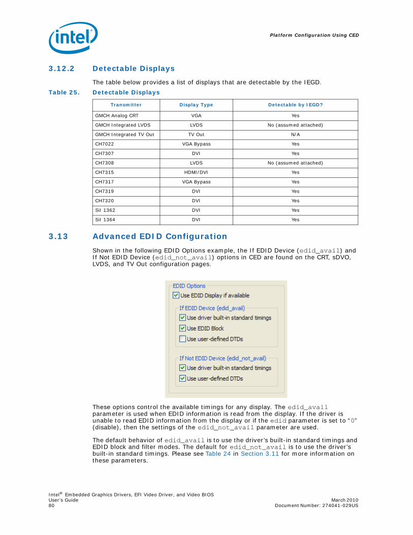
Platform Configuration Using CED
Intel® Embedded Graphics Drivers, EFI Video Driver, and Video BIOSUser’s Guide March 2010 80 Document Number: 274041-029US
3.12.2 Detectable Displays
The table below provides a list of displays that are detectable by the IEGD.
3.13 Advanced EDID Configuration
Shown in the following EDID Options example, the If EDID Device (edid_avail) and If Not EDID Device (edid_not_avail) options in CED are found on the CRT, sDVO, LVDS, and TV Out configuration pages.
These options control the available timings for any display. The edid_avail parameter is used when EDID information is read from the display. If the driver is unable to read EDID information from the display or if the edid parameter is set to “0” (disable), then the settings of the edid_not_avail parameter are used.
The default behavior of edid_avail is to use the driver’s built-in standard timings and EDID block and filter modes. The default for edid_not_avail is to use the driver’s built-in standard timings. Please see Table 24 in Section 3.11 for more information on these parameters.
Table 25. Detectable Displays
Transmitter Display Type Detectable by IEGD?
GMCH Analog CRT VGA Yes
GMCH Integrated LVDS LVDS No (assumed attached)
GMCH Integrated TV Out TV Out N/A
CH7022 VGA Bypass Yes
CH7307 DVI Yes
CH7308 LVDS No (assumed attached)
CH7315 HDMI/DVI Yes
CH7317 VGA Bypass Yes
CH7319 DVI Yes
CH7320 DVI Yes
SiI 1362 DVI Yes
SiI 1364 DVI Yes
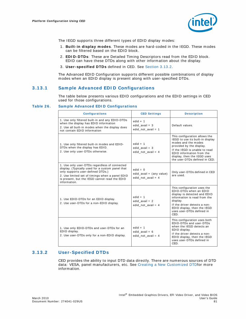
Intel® Embedded Graphics Drivers, EFI Video Driver, and Video BIOSMarch 2010 User’s GuideDocument Number: 274041-029US 81
Platform Configuration Using CED
The IEGD supports three different types of EDID display modes:
1. Built-in display modes. These modes are hard-coded in the IEGD. These modes can be filtered based on the EDID block.
2. EDID-DTDs: These are Detailed Timing Descriptors read from the EDID block. EDID can have these DTDs along with other information about the display.
3. User-specified DTDs defined in CED. See Section 3.13.2.
The Advanced EDID Configuration supports different possible combinations of display modes when an EDID display is present along with user-specified DTDs.
3.13.1 Sample Advanced EDID Configurations
The table below presents various EDID configurations and the EDID settings in CED used for those configurations.
3.13.2 User-Specified DTDs
CED provides the ability to input DTD data directly. There are numerous sources of DTD data: VESA, panel manufacturers, etc. See Creating a New Customized DTDfor more information.
Table 26. Sample Advanced EDID Configurations
Configurations CED Settings Description
1. Use only filtered built-in and any EDID-DTDs when the display has EDID information2. Use all built-in modes when the display does not contain EDID information
edid = 1edid_avail = 3edid_not_avail = 1
Default values.
1. Use only filtered built-in modes and EDID-DTDs when the display has EDID.2. Use only user-DTDs otherwise.
edid = 1edid_avail = 3edid_not_avail = 4
This configuration allows the IEGD to use its built-in display modes and the modes provided by the display. If the IEGD is unable to read EDID information from the display, then the IEGD uses the user-DTDs defined in CED.
1. Use only user-DTDs regardless of connected display. (Typically used for a custom panel that only supports user-defined DTDs.)2. Use limited set of timings when a panel EDID is present, but the IEGD cannot read the EDID information.
edid = 0edid_avail = (any value)edid_not_avail = 4
Only user-DTDs defined in CED are used.
1. Use EDID-DTDs for an EDID display.2. Use user-DTDs for a non-EDID display.
edid = 1edid_avail = 2edid_not_avail = 4
This configuration uses the EDID-DTDs when an EDID display is detected and EDID information is read from the display. If the driver detects a non-EDID display, then the IEGD uses user-DTDs defined in CED.
1. Use only EDID-DTDs and user-DTDs for an EDID display.2. Use user-DTDs only for a non-EDID display.
edid = 1edid_avail = 6edid_not_avail = 4
This configuration uses both EDID-DTDs and user-DTDs when the IEGD detects an EDID display.If the driver detects a non-EDID display, then the IEGD uses user-DTDs defined in CED.

Platform Configuration Using CED
Intel® Embedded Graphics Drivers, EFI Video Driver, and Video BIOSUser’s Guide March 2010 82 Document Number: 274041-029US
3.14 Using an External PCI Graphics Adapter as the Primary Device
The IEGD can be configured to work with an external PCI graphics adapter card as the primary graphics adapter device with the Intel internal graphics device (GMCH) as the secondary graphics device. You can configure your system to boot with a PCI graphics adapter in the System BIOS. When an external PCI graphics adapter is designated as the primary graphics adapter, the Intel GMCH becomes the secondary graphics device.
Note: The term secondary adapter refers to the adapter that is not the boot-up, or VGA-Compatible, adapter. The secondary adapter is not necessarily the secondary display as assigned by the OS.
You can configure an external PCI card to work with the IEGD as follows:
• The external PCI card as the primary graphics adapter and the GMCH internal graphics device as the secondary.
• The external PCI card as the secondary graphics adapter and the GMCH internal graphics device as the primary.
Note: This feature is not supported on Microsoft Windows CE systems.
The IEGD allows you to specify which display is primary, secondary, and tertiary. It allows Twin and Clone configurations on the internal graphics device when the external PCI display is the primary graphics adapter. It also allows Twin and Clone configurations on the internal graphics device when the external PCI device is the secondary graphics adapter.
An external PCI graphics driver runs independently without sharing resources with the IEGD.
The following figures show several configurations when an external PCI adapter is the primary graphics device and when it is the secondary graphics device.
Figure 24 shows an External PCI card as the primary graphics adapter card and the IEGD driver as the secondary. The drivers do not share hardware resources. The OS decides the framebuffer content and handles that by drawing to the respective driver independently.
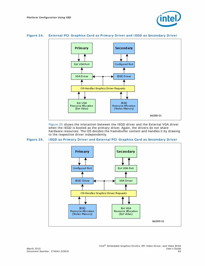
Intel® Embedded Graphics Drivers, EFI Video Driver, and Video BIOSMarch 2010 User’s GuideDocument Number: 274041-029US 83
Platform Configuration Using CED
Figure 25 shows the interaction between the IEGD driver and the External VGA driver when the IEGD is booted as the primary driver. Again, the drivers do not share hardware resources. The OS decides the framebuffer content and handles it by drawing to the respective driver independently.
Figure 24. External PCI Graphics Card as Primary Driver and IEGD as Secondary Driver
Figure 25. IEGD as Primary Driver and External PCI Graphics Card as Secondary Driver

Platform Configuration Using CED
Intel® Embedded Graphics Drivers, EFI Video Driver, and Video BIOSUser’s Guide March 2010 84 Document Number: 274041-029US
Figure 26 shows a sample configuration where the internal graphics device is primary and configured to use two ports to drive two displays while an external PCI graphics adapter is used to drive a tertiary display. Note that regardless of the number of ports being assigned to a driver, the external PCI graphics run independently without sharing resources with the IEGD driver.
3.15 Hybrid Multi-monitor
Hybrid multi-monitor support, defined as a PCI- or PCI Express*-based external graphics card operating concurrently with Intel’s chipset’s integrated graphics, is supported with IEGD.
This feature enables concurrent operation of Intel’s integrated GPU along with a discrete GPU solution, allowing for operability of greater than two independently driven displays. It is also known as “Multi-GPU” and/or “Multi-monitor.”
Intel chipsets that support this feature include the Intel® Q45/G41/G45 Express chipsets and the Intel® GM45/GL40/GS45 Express Mobile chipsets. Please verify with your Intel field representative to determine whether your particular Intel chipset has been validated as supporting this capability before attempting to use this feature.
The external PCI-Express graphics card will need to have “well behaved” VBIOS and drivers for this feature to operate successfully. Failure to operate usually indicates a system BIOS issue, external card VBIOS issue, or external card driver issue.
IEGD is validated as supporting this capability using known good external cards. Inquire with your Intel field representative if your chosen graphics card has been validated as supporting hybrid multi-monitor before attempting this function.
Figure 26. IEGD as Primary Driver with Two Displays and External PCI Driving a Tertiary Display

Intel® Embedded Graphics Drivers, EFI Video Driver, and Video BIOSMarch 2010 User’s GuideDocument Number: 274041-029US 85
Platform Configuration Using CED
For Windows operating systems (such as XP, XP Embedded, Embedded Standard 2009, etc.), Windows Display Properties Settings should be used to manage the heterogeneous display adapters, resolutions, color quality levels, and refresh rates. IEGD and the Display Properties configure the multiple displays appropriately which includes user assignment of Intel’s internal chipset graphics as the primary, secondary, tertiary, or quad ports which dictate where the desktop content will appear. The external graphics card and drivers activate the alternate port(s) not driven by the Intel chipset.
Hybrid multi-monitor support is also enabled by IEGD under most Linux Operating systems.
For more details on this feature and a step-by-step Enablement Process for Hybrid multi-monitor, refer to Intel's white paper titled Hybrid Multi-monitor Support; Enabling new usage models for Intel® Embedded Platforms. This is found on Embedded Design Center at http://edc.intel.com/Software/Downloads/IEGD/#download; search for document number 323214.
3.16 Enhanced Clone Mode Support
The Enhanced Clone Mode feature allows you to specify a clone display size that is different from the primary display. It also allows you to change the clone display size at runtime using the IEGD Runtime GUI (see Section 5.6, “Viewing and Changing the Driver Configuration from Microsoft Windows” on page 113 or Section 7.7, “Runtime Configuration GUI” on page 200 for Linux systems).
In Clone mode, the framebuffer is always allocated to match the primary display size. On the clone display (secondary display) the image is centered if the display is bigger than the framebuffer. Centering is done only if the requested resolution and refresh rate is not available for the clone display.
Extended Clone mode is implemented through the use of four CED parameters:
• Clone Width — allows you to specify a width for the clone display
• Clone Height — allows you to specify a height for the clone display
• Clone Refresh — allows you to specify a refresh rate for the clone display
• Enable interlace mode — allows you to use interlace mode for the clone display
3.16.1 Extended Clone Mode CED Configuration
The following CED screenshot shows a sample Extended Clone mode setting configuration.

Platform Configuration Using CED
Intel® Embedded Graphics Drivers, EFI Video Driver, and Video BIOSUser’s Guide March 2010 86 Document Number: 274041-029US
See also “Sample Clone Mode Configurations”.

Intel® Embedded Graphics Drivers, EFI Video Driver, and Video BIOSMarch 2010 User’s GuideDocument Number: 274041-029US 87
Platform Configuration Using CED
3.16.2 Sample Clone Mode Configurations
The following examples illustrate Clone Mode configurations for the following combinations:
• CRT + integrated LVDS (Example 1 on page 87)
• CRT + Fixed size DVI display (Example 2 on page 87)
Example 1. Mobile Intel® GM45 Express Chipset, Internal LVDS, CRT, and LVDS
This example shows how to set up a clone mode configuration consisting of an internal LVDS, CRT, and external LVDS device.
1. Choose a CRT that supports resolutions larger than 1024x768 and configure the following settings on the Chipset Configuration Page:
— Platform Chipset = Mobile Intel® GM45 Express Chipset
— Display Configuration Mode = Clone
— Clone Width = 1024
— Clone Height = 768
— Clone Refresh = 60
— Port Order = CRT, LVDS
2. Click Next on the Chipset Configuration Page and provide port names for the CRT, LVDS, and sDVO-B port devices.
3. On the LVDS Port Configuration Page, click the Flat Panel Settings button and set the Width and Height to 1024 and 768 respectively.
4. Package and generate an installation for the configuration and move the resulting iegd.inf file to the target machine. (Please see “Creating a New Package” on page 57 for specific instructions.)
After you have moved the iegd.inf file to the target machine, do the following:
1. Set 800x600 on CRT and ensure that an 800x600 image appears at the top, left corner of the LVDS display or that the image has been scaled to match the panel size based on panel used.
2. Set 1280x1024 on CRT and check that the LVDS display is panning. Ensure that the clone mouse pointer is in sync with the primary display.
Example 2. Intel® 915GV, Chrontel 7307, CRT, and DVI
This sample shows how to set up a clone mode configuration consisting of a CRT and DVI display on a Chrontel* 7307 serial sDVO transmitter.
1. Choose a CRT that supports resolutions larger than 1024x768 and configure the following settings on the Chipset Configuration Page:
— Platform Chipset = Intel® 915GV
— Display Configuration Mode = Clone
— Clone Width = 1024
— Clone Height = 768
— Clone Refresh = 60
— Port Order = CRT, sDVO-B
2. Click Next on the Chipset Configuration Page and provide port names for the CRT and sDVO-B port devices.

Platform Configuration Using CED
Intel® Embedded Graphics Drivers, EFI Video Driver, and Video BIOSUser’s Guide March 2010 88 Document Number: 274041-029US
3. On the sDVO-B Port Configuration Page, click the Flat Panel Settings button and set the Width and Height to 1024 and 768 respectively. Select CH7307 from the Select sDVO Device list.
4. Package and generate an installation for the configuration and move the resulting iegd.inf file to the target machine. (Please see “Creating a New Package” on page 57 for specific instructions.)
After you have moved the iegd.inf file to the target machine, do the following:
1. Set 800x600 on CRT and ensure that an 800x600 image appears at the top, left corner of the DVI display or that the image has been scaled to match the panel size based on panel used.
2. Set 1280x1024 on CRT and check that the DVI display is in panning mode. Ensure that the clone mouse pointer is in sync with the primary display.
3.17 Scaling and Centering Configurations
This release supports the following scaling and centering configurations:
• Upscaling for the Chrontel CH7308 LVDS Transmitters
• Internal LVDS Scaling With EDID Panels
• Alignment in Clone mode
• sDVO as Primary
• Render Scaling modes to native panels connected to non-scaling port encoders
See the following topics for configuration details:
• “Upscaling for the Chrontel CH7308 LVDS Transmitters”
• “Internal LVDS Scaling with EDID Panels”
• “Centering Primary Display with Scaling Encoders”
• “Enabling Render Scaling on Port Encoders without Hardware Scaling”
• “Alignment in Clone Mode”
3.17.1 Upscaling for the Chrontel CH7308 LVDS Transmitters
The IEGD can upscale lower-resolution modes (those smaller than the size of the respective panel) to the native size of the panel connected to a Chrontel CH7308* LVDS transmitter.
The IEGD uses a user-supplied DTD with the native flag set (also known as native DTD) as native timing for the panel connected to either a CH7308 transmitter.
If a native DTD is not supplied by the user, the IEGD takes the first available matching FP info width and height timings as native timing for the panel if standard timings were selected as part of edid_avail or edid_not_avail flags.
In order to support upscaling, the LVDS transmitters require the pipe to be set to native timing of the panel regardless of the user selected resolution. It also requires finding the native timing (also known as native DTD) of the panel based on user-supplied configuration information.
The CH7308 (sDVO) port drivers make the list of supported modes limited up to the size of panel. The port drivers also mark one of the timings as native DTD as follows (it goes to the next step only if native DTD is not found in the current step).
Intel® Embedded Graphics Drivers, EFI Video Driver, and Video BIOSMarch 2010 User’s GuideDocument Number: 274041-029US 89
Platform Configuration Using CED
1. It finds the timing with the user-defined DTD with the native DTD flag set. This becomes the native DTD for the panel.
2. If the panel is an EDID panel and user selected to use EDID DTDs, then the port driver marks the EDID DTD as native DTD.
3. If the user supplies a DTD without the native DTD flag set, then the port driver marks this one as the native DTD.
4. If none of the above steps works, the port driver finds the first matching timing for FP width, height and marks it as native DTD.
If none of the above steps work, then there is no native DTD and no upscaling is performed.
3.17.2 Internal LVDS Scaling with EDID Panels
The Internal LVDS connected to an EDID Panel supports scaling of modes other than native mode. To support this, the port driver exports information to the EDID parser that it can scale. The EDID parser does not remove other modes (that is, non-native modes) from the mode table. It only marks the native mode. When the IEGD queries the port driver on which modes are supported, the port driver then removes any modes that cannot be scaled (up or down depending on the port's hardware capability). When mode-setting occurs, the second display in Clone mode can indeed support non-native modes even though the panel had EDID. This occurs only if a native mode can be found the port driver can scale. Otherwise, the port driver ignores the scaling information and the IEGD proceeds normally.
The driver also supports Internal LVDS Scaling on EDID-less panels. The steps that enable this are the same as those described for the scaling of Chrontel LVDS transmitters in Section 3.17.1.
3.17.3 Centering Primary Display with Scaling Encoders
In Clone mode, the IEGD expects the primary display to have a framebuffer size (OS Aware mode) that matches the display’s native size of panel timings. When a display is designated as the primary display in a Clone mode configuration, and the user wants the primary to be centered (as explained in Section 3.17.5), users may want this setup to align a primary display on a scaling encoder with a secondary one that can only center. This will not work by default for certain port encoders such as the internal LVDS, which default to hardware scaling. But IEGD has a mechanism to override hardware scaling thus forcing centering.
When possible, the IEGD allows centering of 640x480, 800x600, and 1024x768 resolutions on the primary display. In some cases (depending on panels), the image may appear on the top-left. It may also produce unusable output on some displays (such as a TV). Thus this type of configuration is more appropriate for LVDS panels.
To disable hardware scaling (and force centering for primary display on above modes), users only need to set the “Panel_Fit” attribute (attribute “0x12”) to ‘0’ (zero).
3.17.4 Enabling Render Scaling on Port Encoders without Hardware Scaling
The IEGD Render Scaling feature allows the driver to support any one of the standard modes (640x480, 800x600, 1024x768 or 1280x1024) as a drawable framebuffer size output to a native panel and connected via a port encoder that does not hardware scale. To achieve this, the GPU engine repeats all rendering operations twice (from the original OS-targeted back buffer) to a separate front buffer, which is rendered via the 3D engine for scaling. This feature is enabled by turning on the “Panel-Fit” attribute

Platform Configuration Using CED
Intel® Embedded Graphics Drivers, EFI Video Driver, and Video BIOSUser’s Guide March 2010 90 Document Number: 274041-029US
(attribute 0x12) on a port driver that does not support that attribute. But this only happens if there is a native mode timing (see Section 3.17.1 for information about how native mode timing is determined).
Users should be aware that this feature can impact performance and produce scaled output which is inferior in quality to hardware encoder scaling.
3.17.5 Alignment in Clone Mode
In Clone mode, both can be configured with separate timings and different resolutions. The content is the same on both displays. In the case where resolutions are different on the cloned displays, the display identified as primary drives the display mode and framebuffer size. There are three options for the cloned displays in this situation:
• Panning: If the clone display is smaller than the primary display, the displayed image can be off the screen with the display showing only a window into the overall image. Panning allows movement of the window, which is viewing the image based on the movements of the cursor.
• Centering: If the clone display is larger than the primary display mode, the display image can be centered in the clone display. Black borders are displayed around the image on the display.
• Scaling: There are two types of scaling in Clone mode, as described below.
— Hardware Encoder Scaling: This feature adjusts the resolution of the image from the primary display to fit the resolution of the clone display. This permits scaling up to a larger display (upscaling), or scaling down to a smaller display (downscaling). It also allows the full image to be displayed within the full resolution of the clone display.Some systems may have cloned displays that cannot scale but have a primary display that can scale (such as an internal LVDS). In non-panning modes (i.e., centering/hardware scaling), this display combination will result in the primary display being scaled up (internal LVDS) but the clone display will be centered. Section 3.17.3 explains how to force the primary display to center — thus allowing both displays to center. Or, Render Scaling as follows explains how to make both displays scale up to full size.
— Render Scaling: For clone display, a situation is possible where the primary display uses a hardware scaling port encoder and the secondary display uses a non-scaling port encoder. Assuming both displays are output via native panels, the resulting output should see the primary scaling of any smaller mode to full panel size. But the secondary display will center the smaller modes. The above explanation (see Hardware Encoder Scaling) explains how to align both displays to be centered. Using the Render Scaling feature, the opposite can be achieved. Ensure the non-scaling encoder is primary and enable Render Scaling on that port (see Section 3.17.4). This will make the GPU render-scale the smaller mode and achieve the full panel size. The clone display (now the scaling encoder) will, however, take the render-scaled image as its input (and output) to the clone display panel. This feature will be upgraded in the future so that the clone display can independently take in the original framebuffer image as its input.
Intel® Embedded Graphics Drivers, EFI Video Driver, and Video BIOSMarch 2010 User’s GuideDocument Number: 274041-029US 91
VBIOS
4.0 VBIOS
4.1 Overview
The Intel Embedded Video BIOS incorporates many of the features and capabilities of the Intel® Embedded Graphics Drivers. The 10.3.1 version of the VBIOS includes support for the following chipsets:
• Intel® Atom™ Processor 400 and 500 Series
• Intel® Q45 Express chipset
• Intel® GM45/GL40/GS45 Express chipset
• Intel® Q35 Express chipset
• Intel® System Controller Hub US15W/US15WP/WPT chipset
Note: When using the IEGD VBIOS on US15W and installing Linux distributions, only text mode is supported, not graphical with some Linux distributions.
Enabling SMSW is one of the instructions that is used when IEGD VBIOS is setting up its caching functions to increase the boot speed during POST and system bring-up. When Linux* distributions fall back to text mode it is a side effect of the Linux Virtual X86 Engine which does not work well with SMSW. Caching is vital for the IEGD VBIOS and it is using SMSW by design. No changes can be made to the IEGD VBIOS as this would affect its performance. If you need to install Linux distributions using a GUI interface, you can use the GMA VBIOS. The IEGD VBIOS can also be used to install the Linux distributions but this must be done in text mode.
4.2 System Requirements
The new Video BIOS can be built on a host Microsoft Windows* system and moved to the target system. The host system must have a 32-bit Microsoft Windows operating system installed with the capability to execute DOS commands from a command line window.
The target system must contain one of the following Intel chipsets:
• Intel® Atom™ Processor 400 and 500 Series
• Intel® Q45/G41/G45 Express chipset
• Intel® GM45/GL40/GS45 Express chipset
• Intel® System Controller Hub US15W/US15WP/WPT chipset
• Intel® Q35 Express chipset
• Mobile Intel® GLE960/GME965 Express chipset
• Intel® Q965 Express chipset
• Mobile Intel® 945GSE Express chipset
• Mobile Intel® 945GME Express chipset
• Intel® 945G Express chipset

VBIOS
Intel® Embedded Graphics Drivers, EFI Video Driver, and Video BIOSUser’s Guide March 2010 92 Document Number: 274041-029US
• Intel® 915GV Express chipset
• Mobile Intel® 915GME Express chipset
• Mobile Intel® 910GMLE Express chipset
The target system must contain a minimum of 64 Mbytes of RAM.
4.3 Configuring and Building the VBIOS with CED
The Intel® Embedded VBIOS is built with the Intel Configuration Editor (CED). The VBIOS will use the configuration that you specify in CED. The VBIOS is selected to be built when you specify the Video BIOS as a Target OS in your package configuration. After specifying the Video BIOS, follow all CED prompts, and be sure to select “Generate VBIOS” when available. The VBIOS will then be built when you select “Generate Installation” in CED.
Before building your VBIOS, you must set up your DOS environment with the steps below.
1. Download the Open Watcom* C/C++ compiler from http://www.openwatcom.com. The User Build System for the VBIOS relies on the Open Watcom C/C++ compiler to be able to build a 16-bit DOS binary required for the BIOS. The VBIOS has been tested with version 1.7a of the Open Watcom compiler.
2. Install the Open Watcom* C/C++ compiler using the full or complete option. Do not use the default installation option as it may cause errors when creating the BIOS in CED.
3. Set up directory paths.You must set up the PATH environment variable in DOS to be able to execute the Watcom compiler. If Watcom was installed with its default path, CED will by default be able to use it.
When you generate a VBIOS, the CED produces the following folders and files:
• Compiled_VBIOS folder
— iegdtsr.exe (Terminate and Stay Resident executable)
— VGA.BIN (Option ROM)
• IEGD_10_3_1_VBIOS.zip (this file is generated by the build system)
The iegdtsr.exe can be copied to any folder on the target machine. To run the TSR, boot the target machine with DOS, and then run the iegdtsr.exe from the DOS command line.
The VGA.bin file is the binary option ROM that can be merged with your system BIOS per the instructions provided by your system BIOS vendor.
The IEGD_10_3_1_VBIOS.zip file contains default builds of the TSR executable and Option ROM for the various chipsets. The filenames are iegdtsr-def.exe and vga-def.bin and are located in the tsr or orom folder of the specific chipset folder (see Figure 27).
For further VBIOS build guidelines, see Section 4.3.3, “Building the VBIOS” on page 95.

Intel® Embedded Graphics Drivers, EFI Video Driver, and Video BIOSMarch 2010 User’s GuideDocument Number: 274041-029US 93
VBIOS
4.3.1 Selecting the Build Folder
The 10.3.1 version of the VBIOS contains specific folders used for creating a VBIOS that is either an option ROM (OROM) that can be merged with the system BIOS, or an executable Terminate and Stay Resident (TSR) program for debugging purposes. There are also separate directories for the different chipsets that are supported. CED will build both the TSR and OROM.
Figure 27 shows the directory structure for the Video BIOS libraries contained within CED.
4.3.2 Configuring the Video BIOS
CED is used to configure the VBIOS. The display settings will be used in the same manner as they are used for the driver.
Figure 27. Video BIOS Directory Structure

VBIOS
Intel® Embedded Graphics Drivers, EFI Video Driver, and Video BIOSUser’s Guide March 2010 94 Document Number: 274041-029US
4.3.2.1 COMMON_TO_PORT
This setting allows you to associate standard display names used in most system BIOSs to specific ports that are recognized by IEGD (e.g., LVDS, sDVO-B, sDVO-C). The VBIOS makes this association when the VBIOS calls the System BIOS Intel® 5F interrupt functions.
This setting is a six digit number, where each digit is associated with one of the system BIOS displays (from left to right):
1 : CRT - Standard analog CRT
2 : TV1 - TV Output 1
3 : EFP1 - DVI Flat Panel 1
4 : LFP - Local Flat Panel (Internal LVDS display)
5 : TV2 - TV Output 2
6 : EFP2 - DVI Flat Panel 2
The values above are an example of the typical displays and corresponding order used by a system BIOS. However, this may vary depending on how your system BIOS has implemented the displays and the Intel 5F interrupt functions.
The value in each position in the setting should be the associated port number. Using the typical settings above, if you want to associate CRT in the system BIOS with the internal CRT (port 5) and LFP in the system BIOS with internal LVDS (port 4) in the VBIOS, set COMMON_TO_PORT to be 500400.
Warning: This feature must be compatible with the system BIOS. If the system BIOS does not properly implement the Intel 5F functions, then using the COMMON_TO_PORT feature could cause unpredictable results with the displays. If you are unsure, set COMMON_TO_PORT to all zeros (000000) to disable this feature.
Note: The displaydetect parameter must be set to Enabled in order for the COMMON_TO_PORT values to be used.
4.3.2.2 post_display_msg
This setting is a binary setting that enables (1) or disables (0) post messages to the display.
4.3.2.3 OEM Vendor Strings
The following settings are string values that allow you to set the values that are returned from the Intel 4F interrupt functions.
oem_string
oem_vendor_name
oem_product_name
oem_product_rev

Intel® Embedded Graphics Drivers, EFI Video Driver, and Video BIOSMarch 2010 User’s GuideDocument Number: 274041-029US 95
VBIOS
4.3.2.4 Default Mode Settings
These settings establish the default VGA or VESA mode to use for the primary (0) and secondary (1) displays. The values should be set to a valid standard VGA or VESA mode (in hexadecimal format, for example, 0x117). Note that a VGA mode can only be set on one display and a second display is disabled unless the DisplayConfig parameter is set to twin or clone mode.
default_mode_0
default_mode_1
4.3.2.5 Default Refresh Settings
These settings allow you to specify which refresh rate is used for certain VESA modes on the primary and secondary displays. For example, mode 0x117 specifies refresh rates of 60 Hz, 75 Hz, and 85 Hz. This setting allows use to specify which of those three rates to use (specified in decimal, e.g., default_refresh_0=60).
default_refresh_0
default_refresh_1
4.3.2.6 default_vga_height
This setting allows you to specify which resolution is used for certain VGA modes. Because only one VGA mode can be supported on both displays, this setting applies to the primary display mode (default_mode_0). For example, mode 3 specifies three possible resolutions: 640x200, 640x350, and 720x400. In this example, setting default_vga_height=350 indicates the resolution 640x350.
4.3.3 Building the VBIOS
CED is used to build the VBIOS. The following steps and screenshots outline a typical CED VBIOS build procedure.
1. Define your configuration via CED, being sure to complete the Video BIOS Configuration Page.
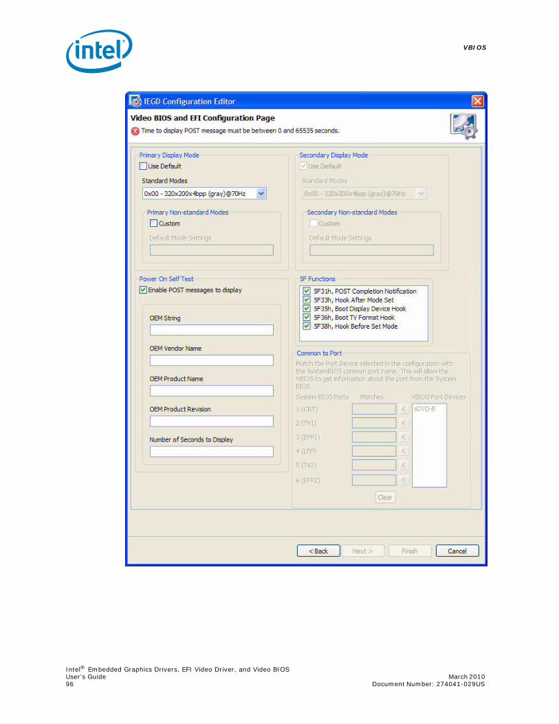
VBIOS
Intel® Embedded Graphics Drivers, EFI Video Driver, and Video BIOSUser’s Guide March 2010 96 Document Number: 274041-029US

Intel® Embedded Graphics Drivers, EFI Video Driver, and Video BIOSMarch 2010 User’s GuideDocument Number: 274041-029US 97
VBIOS
2. When you define the package you are building, be sure to select “Video BIOS” as “Target OS”.
3. Generate the installation. The following may display:
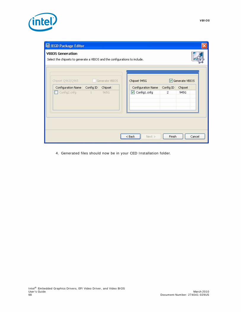
VBIOS
Intel® Embedded Graphics Drivers, EFI Video Driver, and Video BIOSUser’s Guide March 2010 98 Document Number: 274041-029US
4. Generated files should now be in your CED Installation folder.

Intel® Embedded Graphics Drivers, EFI Video Driver, and Video BIOSMarch 2010 User’s GuideDocument Number: 274041-029US 99
VBIOS
4.4 VBIOS, Driver Compatibility, and Data Dependencies
The Intel Embedded Graphics Drivers do not depend on any data from the VBIOS, and will either use driver settings or select default values for the attached displays. This allows the driver to properly operate with incompatible BIOS or BIOS replacements.
The Intel Embedded Graphics Drivers will retrieve settings, such as panel ID and other display settings from the Embedded VBIOS. The Embedded VBIOS allows for configuration of display timings that can also be used for the Intel Embedded Graphics Drivers.
4.5 VESA and VGA Video Modes
The VBIOS supports many VESA and standard VGA modes. See Table 27 and Table 28 for the VGA and VESA modes and vertical refresh rates that are supported by the VBIOS.
Note: Although IBM labeled certain EGA modes with a (*) suffix and the VGA modes with a (+) suffix (such as mode 3, 3* and 3+), the VGA modes are so common that this document does not use the (+) suffix to refer to them.
The actual availability of any particular mode depends on the capabilities of the display device, the amount of memory installed, and other system parameters.

VBIOS
Intel® Embedded Graphics Drivers, EFI Video Driver, and Video BIOSUser’s Guide March 2010 100 Document Number: 274041-029US
Table 27. Supported VGA Video Display Modes
Video Mode
Pixel Resolution
Color Depth (bpp)
Mode Type
Display Adapter
Font Size
Character Resolution
Dot Clock (MHz)
Horiz. Freq. (KHz)
Vert Freq (Hz)
Video Memory (KBytes)
00h
320 x 20016 (gray) (4 bpp)
Text CGA 8 x 8 40 x 25 25 31.5 70 256
320 x 35016 (gray) (4 bpp)
EGA 8 x 14 40 x 25 25 31.5 70 256
360 x 40016
(4 bpp)VGA 9 x 16 40 x 25 28 31.5 70 256
01h
320 x 20016
(4 bpp)Text CGA 8 x 8 40 x 25 25 31.5 70 256
320 x 35016
(4 bpp)EGA 8 x 14 40 x 25 25 31.5 70 256
360 x 40016
(4 bpp)VGA 9 x 16 40 x 25 28 31.5 70 256
02h
640 x 20016 (gray)(4 bpp)
Text CGA 8 x 8 80 x 25 25 31.5 70 256
640 x 35016 (gray)(4 bpp)
EGA 8 x 14 80 x 25 25 31.5 70 256
720 x 40016
(4 bpp)VGA 9 x 16 80 x 25 28 31.5 70 256
03h
640 x 20016
(4 bpp)Text CGA 8 x 8 80 x 25 25 31.5 70 256
640 x 35016
(4 bpp)EGA 8 x 14 80 x 25 25 31.5 70 256
720 x 40016
(4 bpp)VGA 9 x 16 80 x 25 28 31.5 70 256
04h 320 x 200 4 Graph All 8 x 8 40 x 25 25 31.5 70 256
05h
320 x 200 4 (gray) Graph CGA 8 x 8 40 x 25 25 31.5 70 256
320 x 200 4 (gray) EGA 8 x 8 40 x 25 25 31.5 70 256
320 x 200 4 VGA 8 x 8 40 x 25 25 31.5 70 256
06h 640 x 200 2 Graph All 8 x 8 80 x 25 25 31.5 70 256
07h
720 x 350 Mono Text MDA 9 x 14 80 x 25 28 31.5 70 256
720 x 350 Mono EGA 9 x 14 80 x 25 28 31.5 70 256
720 x 400 Mono VGA 9 x 16 80 x 25 28 31.5 70 256
08h-0Ch Reserved - -
0Dh 320 x 20016
(4 bpp)Graph E/VGA 8 x 8 40 x 25 25 31.5 70 256
0Eh 640 x 20016
(4 bpp)Graph E/VGA 8 x 8 80 x 25 25 31.5 70 256
0Fh 640 x 350 Mono Graph E/VGA 8 x 14 80 x 25 25 31.5 70 256
10h 640 x 35016
(4 bpp)Graph E/VGA 8 x 14 80 x 25 25 31.5 70 256
11h 640 x 4802
(4 bpp)Graph VGA 8 x 16 80 x 30 25 31.5 60 256
12h 640 x 48016
(4 bpp)Graph VGA 8 x 16 80 x 30 25 31.5 60 256
13h 320 x 200256
(8 bpp)Graph VGA 8 x 8 40 x 25 25 31.5 70 256
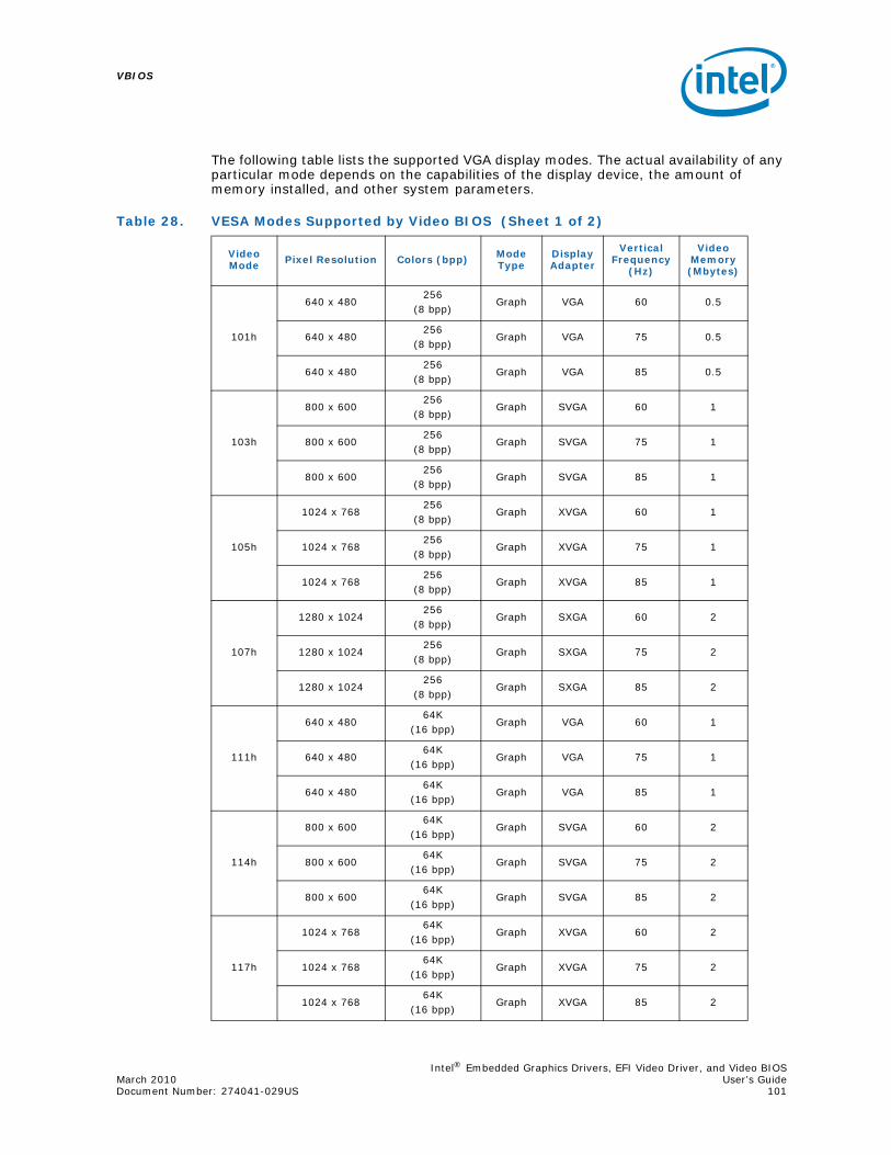
Intel® Embedded Graphics Drivers, EFI Video Driver, and Video BIOSMarch 2010 User’s GuideDocument Number: 274041-029US 101
VBIOS
The following table lists the supported VGA display modes. The actual availability of any particular mode depends on the capabilities of the display device, the amount of memory installed, and other system parameters.
Table 28. VESA Modes Supported by Video BIOS (Sheet 1 of 2)
Video Mode Pixel Resolution Colors (bpp) Mode
TypeDisplay Adapter
Vertical Frequency
(Hz)
Video Memory (Mbytes)
101h
640 x 480256
(8 bpp)Graph VGA 60 0.5
640 x 480256
(8 bpp)Graph VGA 75 0.5
640 x 480256
(8 bpp)Graph VGA 85 0.5
103h
800 x 600256
(8 bpp)Graph SVGA 60 1
800 x 600256
(8 bpp)Graph SVGA 75 1
800 x 600256
(8 bpp)Graph SVGA 85 1
105h
1024 x 768256
(8 bpp)Graph XVGA 60 1
1024 x 768256
(8 bpp)Graph XVGA 75 1
1024 x 768256
(8 bpp)Graph XVGA 85 1
107h
1280 x 1024256
(8 bpp)Graph SXGA 60 2
1280 x 1024256
(8 bpp)Graph SXGA 75 2
1280 x 1024256
(8 bpp)Graph SXGA 85 2
111h
640 x 48064K
(16 bpp)Graph VGA 60 1
640 x 48064K
(16 bpp)Graph VGA 75 1
640 x 48064K
(16 bpp)Graph VGA 85 1
114h
800 x 60064K
(16 bpp)Graph SVGA 60 2
800 x 60064K
(16 bpp)Graph SVGA 75 2
800 x 60064K
(16 bpp)Graph SVGA 85 2
117h
1024 x 76864K
(16 bpp)Graph XVGA 60 2
1024 x 76864K
(16 bpp)Graph XVGA 75 2
1024 x 76864K
(16 bpp)Graph XVGA 85 2

VBIOS
Intel® Embedded Graphics Drivers, EFI Video Driver, and Video BIOSUser’s Guide March 2010 102 Document Number: 274041-029US
11Ah
1280 x 102464K
(16 bpp)Graph SXGA 60 4
1280 x 102464K
(16 bpp)Graph SXGA 75 4
1280 x 102464K
(16 bpp)Graph SXGA 85 4
112
640 x 48016M
(32 bpp)Graph VGA 60 2
640 x 48016M
(32 bpp)Graph VGA 75 2
640 x 48016M
(32 bpp)Graph VGA 85 2
115
800 x 60016M
(32 bpp)Graph SVGA 60 4
800 x 60016M
(32 bpp)Graph SVGA 75 4
800 x 60016M
(32 bpp)Graph SVGA 85 4
118
1024 x 76816M
(32 bpp)Graph XVGA 60 4
1024 x 76816M
(32 bpp)Graph XVGA 75 4
1024 x 76816M
(32 bpp)Graph XVGA 85 4
11B
1280 x 102416M
(32 bpp)Graph SXGA 60 8
1280 x 102416M
(32 bpp)Graph SXGA 75 8
1280 x 102416M
(32 bpp)Graph SXGA 85 8
Table 28. VESA Modes Supported by Video BIOS (Sheet 2 of 2)
Video Mode Pixel Resolution Colors (bpp) Mode
TypeDisplay Adapter
Vertical Frequency
(Hz)
Video Memory (Mbytes)
Intel® Embedded Graphics Drivers, EFI Video Driver, and Video BIOSMarch 2010 User’s GuideDocument Number: 274041-029US 103
Configuring and Installing Microsoft Windows Drivers
5.0 Configuring and Installing Microsoft Windows Drivers
5.1 Editing the Microsoft Windows INF File
This section describes the driver-level information (iegd.inf) for the Microsoft Windows* operating system, which includes the following1:
• Microsoft Windows Embedded Standard 2009*
• Microsoft Windows XP* SP3
• Microsoft Windows XP Professional* SP3
• Microsoft Windows XP Embedded* SP3
• Microsoft WEPOS* SP3
Note: Configuration and Installation information for the Microsoft Windows CE operating system is described in Chapter 6.0, “Configuring and Building the IEGD for Microsoft Windows CE* Systems”.
5.2 Configuration Information
5.2.1 Universal INF Configuration
Multiple display configurations can be specified in a single INF file. Each configuration is uniquely identified by the ConfigId parameter.
The driver reads the PanelId from the System BIOS during initialization and uses the configuration whose ConfigId matches the PanelId. If the System BIOS does not set a valid PanelId (for example, panelId = 0), the driver reads a configuration using ConfigId = 1. (A ConfigId value of 0 is invalid.)
Note: When setting up a multiple display configuration to be used with the PanelID, do not set a default configuration. To have no default configuration, select None from the Default Configuration drop-down menu on the IEGD Package Page. See Section 3.6, “Creating a New Package” on page 57 for details.
You can override the default behavior by specifying a ConfigId parameter as follows:
HKR,, ConfigId, %REG_DWORD%, %DEFAULT_CONFIG_ID%
In this case, the driver ignores the PanelId returned by the System BIOS. Instead, the IEGD uses the configuration information using the specified ConfigId.
1. These versions of the drivers are not WHQL (Windows Hardware Quality Labs) certified.

Configuring and Installing Microsoft Windows Drivers
Intel® Embedded Graphics Drivers, EFI Video Driver, and Video BIOSUser’s Guide March 2010 104 Document Number: 274041-029US
5.2.2 INF File Backward Compatibility
The current version of the IEGD uses the new INF file format. You cannot use the new INF file with pre-5.0 versions of the IEGD. However, you can still use pre-5.0 INF file formats with the current version of the IEGD.
5.2.2.1 INF File Backward Compatibility with IEGD Version 4.0
Version 4.0 of the IEGD provides backward compatibility with pre-4.0 versions of the INF file. This support is implemented through the PcfVersion key in the INF file, shown below:
HKR,, PcfVersion, %REG_DWORD%, 0x0400
The IEGD uses this key to determine which version of the .inf file it is interpreting. When this key is present in the .inf file and its value is 0x0400, the driver reads it as a 4.0 .inf file. If this key is omitted from the .inf file or if its value is less than 0x0400, the driver reads the .inf file as a pre-4.0 file.
Note the following rules:
• If you use a pre-4.0 version of the .inf file with version 4.0 of the IEGD, the driver translates pre-4.0 configuration parameters to 4.0 parameters.
• You cannot use 4.0 parameters in a pre-4.0 .inf file. If you try, the driver ignores them.
• You cannot use pre-4.0 parameters in a 4.0 .inf file. If you try, the driver ignores them.
For example, the usestdtimings parameter is a pre-4.0 parameter. If it is specified in a 4.0 INF file, the driver ignores it. Similarly, if you attempt to add the edid_avail and edid_non_avail parameters to a pre-4.0 .inf file (that is, an .inf file where the PcfVersion key is not present), they are ignored by the driver.
The PcfVersion key is generated automatically by the CED utility and is placed in the [iegd_SoftwareDeviceSettings] section of the .inf file. The default iegd.inf file already contains the PcfVersion key. Please see Appendix A, “Example INF File” to view a sample .inf file.
5.2.3 Dual Panel ConfigurationBelow are the settings required to set the INF file to enable extended display configurations. Typically, these settings are output from the CED utility. However, the INF file may also be edited directly. See Table 29 for a description of these settings.
HKR, Config\%DEFAULT_CONFIG_ID%\General, DisplayConfig, %REG_DWORD%, 8
HKR, Config\%DEFAULT_CONFIG_ID%\General, PortOrder, %REG_SZ%, "52000"
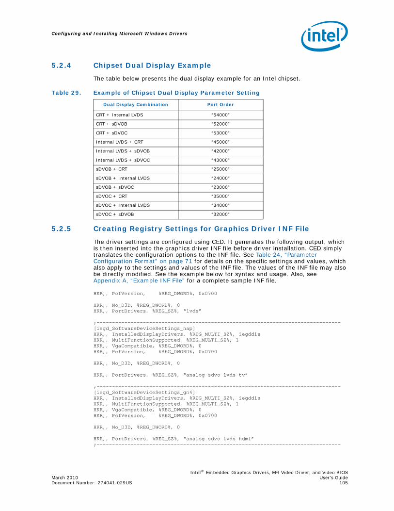
Intel® Embedded Graphics Drivers, EFI Video Driver, and Video BIOSMarch 2010 User’s GuideDocument Number: 274041-029US 105
Configuring and Installing Microsoft Windows Drivers
5.2.4 Chipset Dual Display Example
The table below presents the dual display example for an Intel chipset.
5.2.5 Creating Registry Settings for Graphics Driver INF File
The driver settings are configured using CED. It generates the following output, which is then inserted into the graphics driver INF file before driver installation. CED simply translates the configuration options to the INF file. See Table 24, “Parameter Configuration Format” on page 71 for details on the specific settings and values, which also apply to the settings and values of the INF file. The values of the INF file may also be directly modified. See the example below for syntax and usage. Also, see Appendix A, “Example INF File” for a complete sample INF file.
HKR,, PcfVersion, %REG_DWORD%, 0x0700
HKR,, No_D3D, %REG_DWORD%, 0HKR,, PortDrivers, %REG_SZ%, “lvds”
;-------------------------------------------------------------------------------[iegd_SoftwareDeviceSettings_nap]HKR,, InstalledDisplayDrivers, %REG_MULTI_SZ%, iegddisHKR,, MultiFunctionSupported, %REG_MULTI_SZ%, 1HKR,, VgaCompatible, %REG_DWORD%, 0HKR,, PcfVersion, %REG_DWORD%, 0x0700
HKR,, No_D3D, %REG_DWORD%, 0
HKR,, PortDrivers, %REG_SZ%, “analog sdvo lvds tv”
;-------------------------------------------------------------------------------[iegd_SoftwareDeviceSettings_gn4]HKR,, InstalledDisplayDrivers, %REG_MULTI_SZ%, iegddisHKR,, MultiFunctionSupported, %REG_MULTI_SZ%, 1HKR,, VgaCompatible, %REG_DWORD%, 0HKR,, PcfVersion, %REG_DWORD%, 0x0700
HKR,, No_D3D, %REG_DWORD%, 0
HKR,, PortDrivers, %REG_SZ%, “analog sdvo lvds hdmi”;-------------------------------------------------------------------------------
Table 29. Example of Chipset Dual Display Parameter Setting
Dual Display Combination Port Order
CRT + Internal LVDS “54000”
CRT + sDVOB “52000”
CRT + sDVOC “53000”
Internal LVDS + CRT “45000”
Internal LVDS + sDVOB “42000”
Internal LVDS + sDVOC “43000”
sDVOB + CRT “25000”
sDVOB + Internal LVDS “24000”
sDVOB + sDVOC “23000”
sDVOC + CRT “35000”
sDVOC + Internal LVDS “34000”
sDVOC + sDVOB “32000”
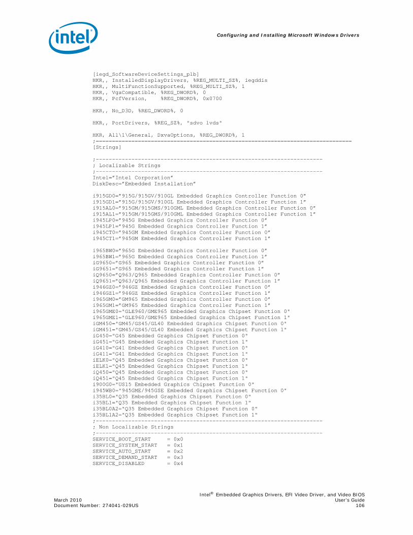
Configuring and Installing Microsoft Windows Drivers
Intel® Embedded Graphics Drivers, EFI Video Driver, and Video BIOSMarch 2010 User’s GuideDocument Number: 274041-029US 106
[iegd_SoftwareDeviceSettings_plb]HKR,, InstalledDisplayDrivers, %REG_MULTI_SZ%, iegddisHKR,, MultiFunctionSupported, %REG_MULTI_SZ%, 1HKR,, VgaCompatible, %REG_DWORD%, 0HKR,, PcfVersion, %REG_DWORD%, 0x0700
HKR,, No_D3D, %REG_DWORD%, 0
HKR,, PortDrivers, %REG_SZ%, "sdvo lvds"
HKR, All\1\General, DxvaOptions, %REG_DWORD%, 1;===============================================================================[Strings]
;----------------------------------------------------------------------; Localizable Strings;----------------------------------------------------------------------Intel=”Intel Corporation” DiskDesc=”Embedded Installation”
i915GD0=”915G/915GV/910GL Embedded Graphics Controller Function 0” i915GD1=”915G/915GV/910GL Embedded Graphics Controller Function 1” i915AL0=”915GM/915GMS/910GML Embedded Graphics Controller Function 0”i915AL1=”915GM/915GMS/910GML Embedded Graphics Controller Function 1” i945LP0=”945G Embedded Graphics Controller Function 0”i945LP1=”945G Embedded Graphics Controller Function 1”i945CT0=”945GM Embedded Graphics Controller Function 0”i945CT1=”945GM Embedded Graphics Controller Function 1”
i965BW0=”965G Embedded Graphics Controller Function 0”i965BW1=”965G Embedded Graphics Controller Function 1”iG9650=”G965 Embedded Graphics Controller Function 0”iG9651=”G965 Embedded Graphics Controller Function 1”iQ9650=”Q963/Q965 Embedded Graphics Controller Function 0”iQ9651=”Q963/Q965 Embedded Graphics Controller Function 1”i946GZ0=”946GZ Embedded Graphics Controller Function 0”i946GZ1=”946GZ Embedded Graphics Controller Function 1”i965GM0=”GM965 Embedded Graphics Controller Function 0”i965GM1=”GM965 Embedded Graphics Controller Function 1”i965GME0="GLE960/GME965 Embedded Graphics Chipset Function 0"i965GME1="GLE960/GME965 Embedded Graphics Chipset Function 1"iGM450="GM45/GS45/GL40 Embedded Graphics Chipset Function 0"iGM451="GM45/GS45/GL40 Embedded Graphics Chipset Function 1"iG450="G45 Embedded Graphics Chipset Function 0"iG451="G45 Embedded Graphics Chipset Function 1"iG410="G41 Embedded Graphics Chipset Function 0"iG411="G41 Embedded Graphics Chipset Function 1"iELK0="Q45 Embedded Graphics Chipset Function 0"iELK1="Q45 Embedded Graphics Chipset Function 1"iQ450="Q45 Embedded Graphics Chipset Function 0"iQ451="Q45 Embedded Graphics Chipset Function 1"i900G0="US15 Embedded Graphics Chipset Function 0"i945WB0="945GME/945GSE Embedded Graphics Chipset Function 0"i35BL0="Q35 Embedded Graphics Chipset Function 0"i35BL1="Q35 Embedded Graphics Chipset Function 1"i35BL0A2="Q35 Embedded Graphics Chipset Function 0"i35BL1A2="Q35 Embedded Graphics Chipset Function 1";----------------------------------------------------------------------; Non Localizable Strings;----------------------------------------------------------------------SERVICE_BOOT_START = 0x0 SERVICE_SYSTEM_START = 0x1 SERVICE_AUTO_START = 0x2 SERVICE_DEMAND_START = 0x3 SERVICE_DISABLED = 0x4
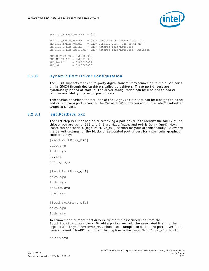
Intel® Embedded Graphics Drivers, EFI Video Driver, and Video BIOSMarch 2010 User’s GuideDocument Number: 274041-029US 107
Configuring and Installing Microsoft Windows Drivers
SERVICE_KERNEL_DRIVER = 0x1
SERVICE_ERROR_IGNORE = 0x0; Continue on driver load fail SERVICE_ERROR_NORMAL = 0x1; Display warn, but continueSERVICE_ERROR_SEVERE = 0x2; Attempt LastKnownGoodSERVICE_ERROR_CRITICAL = 0x3; Attempt LastKnownGood, BugCheck
REG_EXPAND_SZ = 0x00020000REG_MULTI_SZ = 0x00010000REG_DWORD = 0x00010001REG_SZ = 0x00000000
5.2.6 Dynamic Port Driver Configuration
The IEGD supports many third-party digital transmitters connected to the sDVO ports of the GMCH though device drivers called port drivers. These port drivers are dynamically loaded at startup. The driver configuration can be modified to add or remove availability of specific port drivers.
This section describes the portions of the iegd.inf file that can be modified to either add or remove a port driver for the Microsoft Windows version of the Intel® Embedded Graphics Drivers.
5.2.6.1 iegd.PortDrvs_xxx
The first step in either adding or removing a port driver is to identify the family of the chipset you are using. 915 and 945 are Napa (nap), and 965 is Gen 4 (gn4). Next locate the appropriate [iegd.PortDrvs_xxx] section for your graphics family. Below are the default settings for the blocks of associated port drivers for a particular graphics chipset family:
[iegd.PortDrvs_nap]
sdvo.sys
lvds.sys
tv.sys
analog.sys
[iegd.PortDrvs_gn4]
sdvo.sys
lvds.sys
analog.sys
hdmi.sys
[iegd.PortDrvs_plb]
sdvo.sys
lvds.sys
To remove one or more port drivers, delete the associated line from the iegd.PortDrvs_xxx block. To add a port driver, add the associated line into the appropriate iegd.PortDrvs_xxx block. For example, to add a new port driver for a device named “NewPD”, add the following line to the iegd.PortDrvs_alm block:
NewPD.sys

Configuring and Installing Microsoft Windows Drivers
Intel® Embedded Graphics Drivers, EFI Video Driver, and Video BIOSUser’s Guide March 2010 108 Document Number: 274041-029US
5.2.6.2 SourceDisksFiles
The next step to either add or remove a port driver is to identify the specific port driver file names in the SourceDisksFiles blocks. The default settings are as follows:[SourceDisksFiles]iegdmini.sys = 1iegddis.dll = 1iegd3dg3.dll = 1iegd3dg4.dll = 1lvds.sys = 1sdvo.sys = 1tv.sys = 1hdmi.sys = 1sdvo.vp = 1hdmi.vp = 1analog.vp = 1lvds.vp = 1tv.vp = 1iegdckey.vp = 1iegdmsys.vp = 1iegdcagt.cpa = 1iegdcagt.vp = 1iegd3dga.dll = 1iegdglga.dll = 1libGLES_CM.dll = 1libGLESv2.dll = 1analog.sys = 1
To remove a port driver, delete the associated line in the [SourceDisksFiles] block. To add a port driver, add the associated line to the block. For example, to add a port driver for a device whose driver is named NewPD.sys, add the following line:
NewPD.sys = 1
5.2.6.3 PortDrivers Registry Key
The next step is to modify the registry key in the appropriate [iegd_SoftwareDeviceSettings_xxx] section that defines the list of available port drivers. Below are the default values of this registry key in the iegd.inf file:
For the [iegd_SoftwareDeviceSettings_nap] block:HKR,, PortDrivers, %REG_SZ%, “sdvo lvds tv”
For the [iegd_SoftwareDeviceSettings_gn4] block:HKR,, PortDrivers, %REG_SZ%, “sdvo lvds”
Remove or add port driver names as appropriate to the list of port drivers specified within the quoted string. For example, to add support for a new port driver named “NewPD”, the registry key would be defined as follows:
HKR,, PortDrivers, %REG_SZ%, "lvds NewPD"

Intel® Embedded Graphics Drivers, EFI Video Driver, and Video BIOSMarch 2010 User’s GuideDocument Number: 274041-029US 109
Configuring and Installing Microsoft Windows Drivers
5.2.7 Creating an .sld file for Microsoft Windows XP Embedded Systems
Microsoft Windows XP Embedded* operating systems require the use of an .sld (system level definitions) file. The following steps detail how to create such a file for IEGD from your custom iegd.inf file that you created using CED.
1. Run Component Designer.
2. In the File menu, select Import.
3. In the Choose File for Import dialog, select Setup Information files (*.inf). in the File of type drop-down list.
4. Select iegd.inf from installation directory.
5. In the Inf Processing Options dialog, select Automatic in the Parsing Options dialog and click OK.
6. Click Start in the Import File dialog box. Close the dialog on completion. There should not be any errors.
7. If there are no errors, Save the .sld file.
8. Run Component Database Manager and import the .sld file created above.
Note: Multiple versions will be created.
9. To move the binaries, copy the IEGD/driver files into the root repository:\Windows Embedded Data\Repository
10. In Target Designer, all the IEGD drivers are found under Hardware\Devices\Display Adapters and can be selected by dragging and dropping into your build.
5.2.8 Changing Default Display Mode
After installing the Intel® Embedded Graphics Drivers, Microsoft Windows selects a default display mode for the initial startup of the system. This is a 800 x 600 resolution in 4-bit, 16-bit, or even 32-bit color mode.
The display modes are set through CED; however if you want to change the settings using the registry keys, you may add the following lines to the [iegd_SoftwareDeviceSettings]section of the iegd.inf file:
HKR,, DefaultSettings.XResolution, %REG_DWORD%, 1024
HKR,, DefaultSettings.YResolution, %REG_DWORD%, 768
HKR,, DefaultSettings.BitsPerPel, %REG_DWORD%, 32
HKR,, DefaultSettings.VRefresh, %REG_DWORD%, 60
The example above makes the default resolution 1024 x 768, with a 32-bit color depth and a refresh rate of 60 MHz.
5.3 Installing the IEGD on Microsoft Windows
You can install and uninstall the IEGD on a Microsoft Windows system by using the setup.exe program located in the Windows\Utilities folder. The following procedure shows how to install the IEGD. Section 5.4, “Uninstalling the Current Version of the Driver” on page 112 provides instructions for uninstalling the current version of the IEGD.
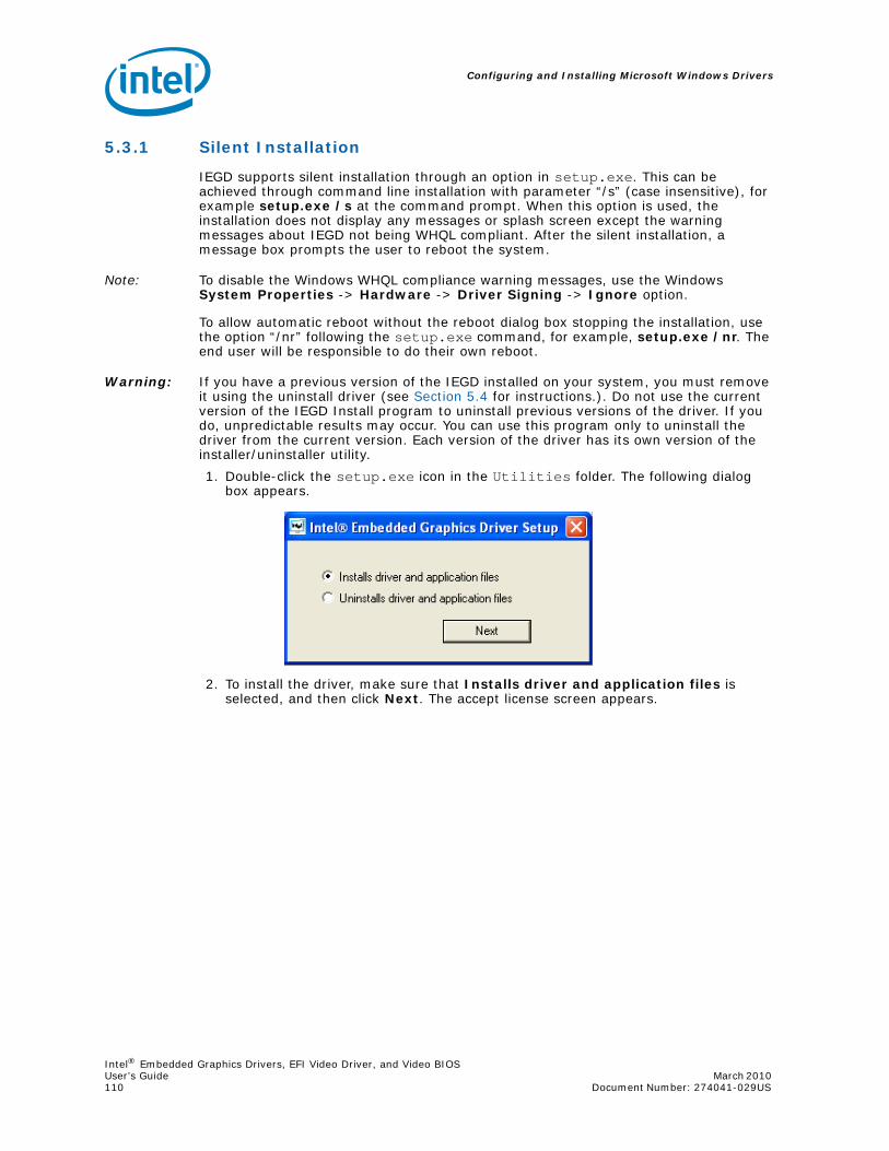
Configuring and Installing Microsoft Windows Drivers
Intel® Embedded Graphics Drivers, EFI Video Driver, and Video BIOSUser’s Guide March 2010 110 Document Number: 274041-029US
5.3.1 Silent Installation
IEGD supports silent installation through an option in setup.exe. This can be achieved through command line installation with parameter “/s” (case insensitive), for example setup.exe /s at the command prompt. When this option is used, the installation does not display any messages or splash screen except the warning messages about IEGD not being WHQL compliant. After the silent installation, a message box prompts the user to reboot the system.
Note: To disable the Windows WHQL compliance warning messages, use the Windows System Properties -> Hardware -> Driver Signing -> Ignore option.
To allow automatic reboot without the reboot dialog box stopping the installation, use the option “/nr” following the setup.exe command, for example, setup.exe /nr. The end user will be responsible to do their own reboot.
Warning: If you have a previous version of the IEGD installed on your system, you must remove it using the uninstall driver (see Section 5.4 for instructions.). Do not use the current version of the IEGD Install program to uninstall previous versions of the driver. If you do, unpredictable results may occur. You can use this program only to uninstall the driver from the current version. Each version of the driver has its own version of the installer/uninstaller utility.
1. Double-click the setup.exe icon in the Utilities folder. The following dialog box appears.
2. To install the driver, make sure that Installs driver and application files is selected, and then click Next. The accept license screen appears.

Intel® Embedded Graphics Drivers, EFI Video Driver, and Video BIOSMarch 2010 User’s GuideDocument Number: 274041-029US 111
Configuring and Installing Microsoft Windows Drivers
3. Click I agree, and then click Install. The installation begins and shows a progress bar as follows:
Note: If you get an “unsigned driver” warning, disregard and click Continue to allow the installation to continue.
4. After the driver and application files have been copied, the system must be restarted to complete the installation. If you want the installation program to restart your computer, click Yes.

Configuring and Installing Microsoft Windows Drivers
Intel® Embedded Graphics Drivers, EFI Video Driver, and Video BIOSUser’s Guide March 2010 112 Document Number: 274041-029US
5.4 Uninstalling the Current Version of the Driver
You can use the setup.exe Microsoft Windows GUI program to remove the driver from your system. When you run the uninstaller program, it removes the following items from the system:
• The IEGD drivers
• The .inf and .pnf files from the windows\system32\inf folder.
• The DisplayPage.dll and qt-mt332.dll from the windows\system32 folder
• Data registry items by running regsvr32.exe with the uninstall option.
Warning: If you have a previous version of the IEGD installed on your system, you must remove it. Do not use the current version of the IEGD Install program to uninstall previous versions of the driver. If you do, unpredictable results may occur. You can use this program only to uninstall the driver from the current version. Each version of the driver has its own version of the installer/uninstaller utility.
1. Click the setup.exe icon located in the Utilities subfolder of the Windows folder.
2. In the dialog box, select Uninstalls driver and application files, and then click Next. The following prompt appears:
3. Click Yes to remove the driver. A progress bar displays and when the driver has been removed, the following screen appears.
4. To complete the uninstallation, you must restart your system. If you want to restart your system now, click Yes in the following dialog box.

Intel® Embedded Graphics Drivers, EFI Video Driver, and Video BIOSMarch 2010 User’s GuideDocument Number: 274041-029US 113
Configuring and Installing Microsoft Windows Drivers
5.5 Run-Time Operation
Resolution, refresh rate, and color bit depth can be changed after installation and reboot via a Microsoft Windows display property sheet. On Microsoft Windows XP, extended desktop can be enabled and disabled, along with swapping primary and secondary displays. Other operations such as enabling and disabling ports (display output), rotation, port configuration, and attribute control are accessible via the standard display driver escape protocol.
5.6 Viewing and Changing the Driver Configuration from Microsoft Windows
Note: IEGDGUI requires that the MS Sans Serif(8) font is installed in the system font folder for correct display.
You can change certain configuration attributes of the IEGD using the iegdgui.exe program located in the \Utilities folder. On Microsoft Windows XP systems, you can access the IEGD configuration on the display properties setting tab. This program launches the IEGD Configuration GUI that consists of the following four tabs:
• Driver Info — Contains the driver information.
• Display Config — Contains current display information and allows configuration of display configurations, display resolutions and bit depth for primary and secondary displays, flip, rotation, and enabling/disabling for a given port.
• Display Attributes — Contains the supported Port Driver (PD) attributes and allows configuration of PD attributes.
• Color Correction — Contains color-correction information for the framebuffer and overlay. Using this tab, you can change the framebuffer and overlay color settings.
To view or change the driver settings using the GUI interface, follow this procedure.
1. Double-click the iegdgui.exe icon in the Utilities folder. On Microsoft Windows XP systems, you can select Display from the control panel or right-click from the desktop and select Properties - Settings - Advanced - Driver info to show information about the driver.To change display configuration, mode, and display setting, select Display Config.

Configuring and Installing Microsoft Windows Drivers
Intel® Embedded Graphics Drivers, EFI Video Driver, and Video BIOSUser’s Guide March 2010 114 Document Number: 274041-029US
2. Click the Display Config tab to show the current configuration.
Figure 28. Example Runtime Configuration GUI — Driver Info Tab
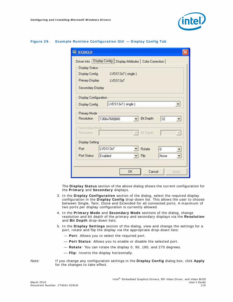
Intel® Embedded Graphics Drivers, EFI Video Driver, and Video BIOSMarch 2010 User’s GuideDocument Number: 274041-029US 115
Configuring and Installing Microsoft Windows Drivers
The Display Status section of the above dialog shows the current configuration for the Primary and Secondary displays.
3. In the Display Configuration section of the dialog, select the required display configuration in the Display Config drop-down list. This allows the user to choose between Single, Twin, Clone and Extended for all connected ports. A maximum of two ports per display configuration is currently allowed.
4. In the Primary Mode and Secondary Mode sections of the dialog, change resolution and bit depth of the primary and secondary displays via the Resolution and Bit Depth drop-down lists.
5. In the Display Settings section of the dialog, view and change the settings for a port, rotate and flip the display via the appropriate drop-down lists:
— Port: Allows you to select the required port.
— Port Status: Allows you to enable or disable the selected port.
— Rotate: You can rotate the display 0, 90, 180, and 270 degrees.
— Flip: Inverts the display horizontally.
Note: If you change any configuration settings in the Display Config dialog box, click Apply for the changes to take effect.
Figure 29. Example Runtime Configuration GUI — Display Config Tab

Configuring and Installing Microsoft Windows Drivers
Intel® Embedded Graphics Drivers, EFI Video Driver, and Video BIOSUser’s Guide March 2010 116 Document Number: 274041-029US
6. Click the Display Attributes tab to view and change the attributes for a port. The screen that appears depends upon the port drivers used.
The figure above shows the attributes that can be changed for the selected port in the Port drop-down list. You can change the Port Driver by selecting the appropriate one for your device. The attributes that appear on this tab depend upon the selected port driver. Please see Appendix B, “Port Driver Attributes,” for a complete list of port driver attributes.
7. Click the Color Correction tab to view and change color corrections. Figure 31 shows a sample Color Correction tab screen.Color Correction is available for both overlays and framebuffers.
Figure 30. Example Runtime Configuration GUI — Display Attributes Tab

Intel® Embedded Graphics Drivers, EFI Video Driver, and Video BIOSMarch 2010 User’s GuideDocument Number: 274041-029US 117
Configuring and Installing Microsoft Windows Drivers
Figure 31. Example Runtime Configuration GUI — Color Correction Tab
Table 30. Framebuffer Color Correction Values (applies to R, G, B color)
Gamma: 0.6 to 6.0 (default value is 1)
Brightness: -127 to 127 (default value is 0)
Contrast: -127 to 127 (default value is 0)
Table 31. Overlay Color Correction Values (applies to ALL color)
Gamma: 0.6 to 6.0 (default value is 1)
Brightness: 0 to 200 (default value is 100)
Contrast: 0 to 200 (default value is 100)
Saturation: 0 to 200 (default value is 100)

Configuring and Installing Microsoft Windows Drivers
Intel® Embedded Graphics Drivers, EFI Video Driver, and Video BIOSUser’s Guide March 2010 118 Document Number: 274041-029US
The following sub-steps present an example color-correction procedure:
a. Select Framebuffer in the Surface section and select the appropriate port for the color correction to be applied to or select Overlay in the Surface section for color correction to be applied to the overlay.
b. Select the required color to be corrected in the Color section.
c. Select the required color attribute to be corrected in the Gamma Correction section.
d. Click Restore Defaults to restore the default values.
Note: If you make any changes to the color-correction settings, click Apply to have the changes take effect.
Note: The hardware does not support brightness, saturation, and contrast of the overlay and second overlay with RGB pixel format.
Intel® Embedded Graphics Drivers, EFI Video Driver, and Video BIOSMarch 2010 User’s GuideDocument Number: 274041-029US 119
Configuring and Building the IEGD for Microsoft Windows CE* Systems
6.0 Configuring and Building the IEGD for Microsoft Windows CE* Systems
6.1 Overview
This section describes the driver-level information for Microsoft Windows CE* operating systems.
The Microsoft Windows CE drivers are configured and built from the options provided on the General Settings Page (see “Creating a New Configuration” on page 36) and the Microsoft Windows CE Options Page (see page 41). After you configure the IEGD for a Microsoft Windows CE system, package the IEGD and generate an installation. The CED produces an iegd.reg (see “Sample iegd.reg File” on page 138) file and a IEGD_10_3_1_WINCEXX.zip file (where XX is either 5_0 or 6_0) that you use to build an image for a Microsoft Windows CE system using the Microsoft Windows CE Platform Builder.
To build an IEGD image for a Microsoft Windows CE system, the following are the general steps. For specific instructions for the particular version of Windows CE that you are using, either 5.0 or 6.0, refer to the appropriate section.
1. Enter IEGD configuration settings using the CED. (Please see “Creating a Configuration in CED – Summary Steps” on page 30 and “Creating a New Package” on page 57.)
2. Package the configuration. (See “Creating a New Package” on page 57.)
3. Generate an installation using the Generate Installation option on the CED main window (see “Generating an Installation” on page 66). This produces an iegd.reg file and an IEGD_5_0_WINCEXX.zip file. The iegd.reg file contains registry entries and the IEGD_10_3_1_WINCEXX.zip file contains required driver files.
4. Integrate the iegd.reg file with the Microsoft Windows CE Platform Builder. Please see “Integrating IEGD with Microsoft Windows CE* Platform Builder” on page 120.
6.2 Microsoft Windows CE* Installation
The following sections describe how to install the IEGD on the Microsoft Windows CE* 5.0 operating system. For instructions on installing Windows CE 6.0, see Section 6.2.3, “Microsoft Windows CE* 6.0 Installation” on page 122.

Configuring and Building the IEGD for Microsoft Windows CE* Systems
Intel® Embedded Graphics Drivers, EFI Video Driver, and Video BIOSUser’s Guide March 2010 120 Document Number: 274041-029US
6.2.1 Prerequisites
The development system should have the following software installed:
• Microsoft Windows XP* Professional, SP3
• Platform Builder for Microsoft Windows CE* 5.0 or 6.0 (with latest service packs)
The target system must contain one of the following Intel chipsets:
• Intel® Atom™ Processor 400 and 500 Series
• Intel® Q45/G41/G45 Express chipset
• Intel® GM45/GL40/GS45 Express chipset
• Intel® System Controller Hub US15W/US15WP/WPT chipset
• Intel® Q35 Express chipset
• Mobile Intel® GLE960/GME965 Express chipset
• Intel® Q965 Express chipset
• Mobile Intel® 945GSE Express chipset
• Mobile Intel® 945GME Express chipset
• Intel® 945G Express chipset
• Intel® 915GV Express chipset
• Mobile Intel® 915GME Express chipset
• Mobile Intel® 910GMLE Express chipset
The target system must contain a minimum of 64 Mbytes of RAM.
6.2.2 Integrating IEGD with Microsoft Windows CE* Platform Builder
The integration/installation of the driver binaries depends upon the requirements of the target device; while ddi_iegd.dll is required, port drivers may be optionally included.
Note: Windows CE* 6.0 does not employ the catalog file mentioned below. For Windows CE 5.0, to integrate the driver binaries into the Platform Builder, the catalog file included with the release should first be imported to the Platform Builder's catalog (for details about how this is done, see Section 6.2.2.1). After the catalog file is imported, find “Intel Embedded Graphics Driver” under Third Party -> Device Drivers -> Display and drag-and-drop it into the BSP.
In order for the Platform Builder to use IEGD, the iegd.reg file included with the release has to be properly included into the BSP. For Windows CE 5.0, this means adding the following lines into the platform.reg file. Note that you must specify the correct path to the iegd.reg file.

Intel® Embedded Graphics Drivers, EFI Video Driver, and Video BIOSMarch 2010 User’s GuideDocument Number: 274041-029US 121
Configuring and Building the IEGD for Microsoft Windows CE* Systems
;*******************************************************;* IEGD Section for Windows CE 5.0 Platform Builder;*******************************************************IF BSP_DISPLAY_IEGD
; @CESYSGEN IF CE_MODULES_PCI
; GWES will be able to auto-detect the display adapter if a candidate value ; points to the adapter's PCI instance. Values from Candidate1 to Candidate32; (decimal) are possible; GWES will examine them sequentially until it finds; a match.[HKEY_LOCAL_MACHINE\System\GDI\DisplayCandidates]
"Candidate6"="Drivers\\Display\\Intel"
[$(PCI_BUS_ROOT)\Template\IEGD]"DisplayDll"="ddi_iegd.dll""Class"=dword:03"SubClass"=dword:00"ProgIF"=dword:00
"VendorID"=multi_sz:"8086", "8086", "8086", "8086", "8086", "8086", "8086", "8086", "8086", "8086", "8086", "8086", "8086", "8086", "8086", "8086", "8086", "8086", "8086", "8086", "8086", "8086", "8086", "8086", "8086", "8086", "8086""DeviceID"=multi_sz:"3582", "2572", "2562", "357B", "3577", "1132", "7125", "7123", "7121", "2582", "2782", "2592", "2792", "2772", "2776", "27A2", "27A6", "2982", "2983", "29A2", "29A3", "2992", "2993", "2972", "2973", "2A12", "8108"; include the path to the iegd.reg file in the release package#include <specify_path_here>\iegd.reg
; @CESYSGEN ENDIF CE_MODULES_PCIENDIF ; BSP_DISPLAY_IEGD
Finally, to include the actual driver binaries into the OS image, you must reference them in the BSP's BIB file by appending the path to ddi_iegd.dll and the port drivers into platform.bib, as shown below.
Figure 32. Sample FILES Block from platform.bib File
FILES
; Name Path Memory Type
; ----------------------- ------------------------ -----------
; @CESYSGEN ENDIF CE_MODULES_DEVICE
; @CESYSGEN IF CE_MODULES_DEVICE
ddi_iegd.dll <specify_path_here>\ddi_iegd.dll NK

Configuring and Building the IEGD for Microsoft Windows CE* Systems
Intel® Embedded Graphics Drivers, EFI Video Driver, and Video BIOSUser’s Guide March 2010 122 Document Number: 274041-029US
6.2.2.1 Catalog Feature File
For Windows CE*, IEGD’s Catalog Feature File, iegd.cec, is provided in the release package. To import IEGD into the workspace’s catalog, complete the following steps:
1. From the File menu, select Manage Catalog Features.
2. Choose Import.
3. In the Import Catalog Features dialog box, select the .cec file, and then click Open.
4. From the View menu, select Catalog to display the Catalog.
6.2.3 Microsoft Windows CE* 6.0 Installation
6.2.3.1 Prerequisites
The development system should have the following software installed:
• Windows CE* 6.0 R2
• Latest Monthly Updates from the Microsoft Web site dated only until June 2009
• Intel Embedded Graphics Driver (IEGD) v8.0 or later
6.2.3.2 CED Requirements
1. Follow instructions in sections Section 3.5, “Creating a New Configuration” on page 36.
2. Create a folder on the Platform Builder machine to hold IEGD-specific files.
3. Move your IEGD installation ZIP file the folder created in step 2 and extract the ZIP file contents.It is recommended that you extract the files and keep them in one source directory for purposes of this build and then follow instructions in Section 6.2.3.3.
6.2.3.3 Platform Builder Requirements
You must configure your Platform Builder parameters specific to the options that the system and image require, for example, options for the operating system. A Board Support Package (BSP) is also required however, configuration steps for the BSP are beyond the scope of this procedure. An Intel® BSP can be used or the CEPC BSP that is included Platform Builder.
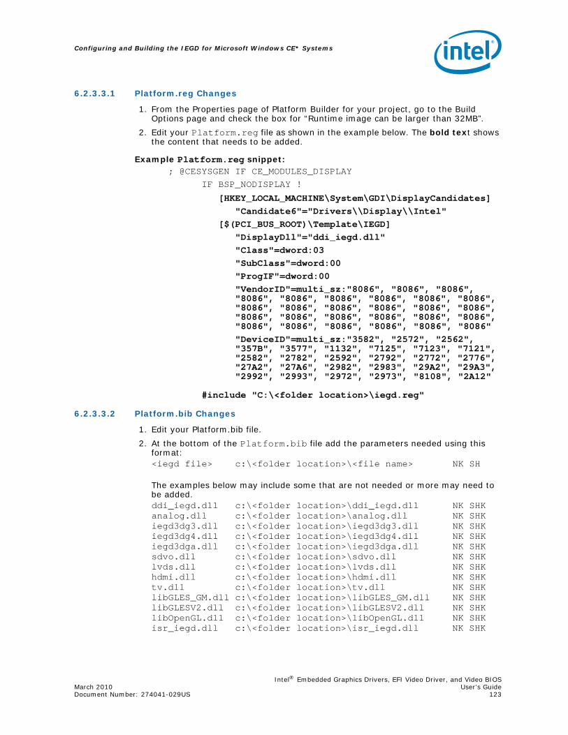
Intel® Embedded Graphics Drivers, EFI Video Driver, and Video BIOSMarch 2010 User’s GuideDocument Number: 274041-029US 123
Configuring and Building the IEGD for Microsoft Windows CE* Systems
6.2.3.3.1 Platform.reg Changes
1. From the Properties page of Platform Builder for your project, go to the Build Options page and check the box for “Runtime image can be larger than 32MB”.
2. Edit your Platform.reg file as shown in the example below. The bold text shows the content that needs to be added.
Example Platform.reg snippet:; @CESYSGEN IF CE_MODULES_DISPLAY
IF BSP_NODISPLAY !
[HKEY_LOCAL_MACHINE\System\GDI\DisplayCandidates]"Candidate6"="Drivers\\Display\\Intel"
[$(PCI_BUS_ROOT)\Template\IEGD]"DisplayDll"="ddi_iegd.dll""Class"=dword:03"SubClass"=dword:00"ProgIF"=dword:00"VendorID"=multi_sz:"8086", "8086", "8086", "8086", "8086", "8086", "8086", "8086", "8086", "8086", "8086", "8086", "8086", "8086", "8086", "8086", "8086", "8086", "8086", "8086", "8086", "8086", "8086", "8086", "8086", "8086", "8086""DeviceID"=multi_sz:"3582", "2572", "2562", "357B", "3577", "1132", "7125", "7123", "7121", "2582", "2782", "2592", "2792", "2772", "2776", "27A2", "27A6", "2982", "2983", "29A2", "29A3", "2992", "2993", "2972", "2973", "8108", "2A12"
#include "C:\<folder location>\iegd.reg"
6.2.3.3.2 Platform.bib Changes
1. Edit your Platform.bib file.
2. At the bottom of the Platform.bib file add the parameters needed using this format:<iegd file> c:\<folder location>\<file name> NK SH
The examples below may include some that are not needed or more may need to be added. ddi_iegd.dll c:\<folder location>\ddi_iegd.dll NK SHKanalog.dll c:\<folder location>\analog.dll NK SHKiegd3dg3.dll c:\<folder location>\iegd3dg3.dll NK SHKiegd3dg4.dll c:\<folder location>\iegd3dg4.dll NK SHKiegd3dga.dll c:\<folder location>\iegd3dga.dll NK SHKsdvo.dll c:\<folder location>\sdvo.dll NK SHKlvds.dll c:\<folder location>\lvds.dll NK SHKhdmi.dll c:\<folder location>\hdmi.dll NK SHKtv.dll c:\<folder location>\tv.dll NK SHKlibGLES_GM.dll c:\<folder location>\libGLES_GM.dll NK SHKlibGLESV2.dll c:\<folder location>\libGLESV2.dll NK SHKlibOpenGL.dll c:\<folder location>\libOpenGL.dll NK SHKisr_iegd.dll c:\<folder location>\isr_iegd.dll NK SHK

Configuring and Building the IEGD for Microsoft Windows CE* Systems
Intel® Embedded Graphics Drivers, EFI Video Driver, and Video BIOSUser’s Guide March 2010 124 Document Number: 274041-029US
6.2.4 Integrating IEGD DirectX DirectShow Codecs for Intel® System Controller Hub US15W
6.2.4.1 IEGD DirectShow Codecs Overview
Microsoft's DirectX DirectShow infrastructure provides a standardized interface for middleware audio-video codec software libraries to expose features for accelerating video and audio processing. This infrastructure does not differentiate between hardware and software acceleration but the middleware codec libraries have the choice of employing either methods. For the purpose of enabling hardware accelerated video decode on Windows CE 6.0, the IEGD Windows CE DirectShow filters are provided in the form of middleware codec libraries (DLLs) that will interface with the IEGD Windows CE driver to operate.
The IEGD DirectShow package includes the following Windows CE 6.0 codecs that are DirectShow transform filters in .dll binary form:
• mpeg2_dec_filter.dll
• mpeg2_spl_filter.dll
• mpeg4_dec_filter.dll
• mpeg4_spl_filter.dll
• h264_dec_filter.dll
• aac_dec_filter.dll
• ac3_dec_filter.dll
The codecs with “spl” are splitter codecs. The aac_dec_filter and ac3_dec_filter are AAC and AC3 audio decoder codecs respectively. The rest are video decode codecs.
Notes: IEGD DirectShow codecs are supported only on the Windows CE 6.0 operating system.
IEGD splitter filters can connect with most source filters but have been verified to connect only with IEGD transform filters on its downstream pins. The same case is true with respect to IEGD transform filter connection with upstream splitter filters.
Important: IEGD audio and video codec filters work only with IEGD splitter filters. If these codecs are installed properly into the Windows CE OS image (via registry changes), the CEPlayer.exe is able to load and use IEGD codecs without any help.
6.2.4.2 Installing IEGD DirectShow Codecs
Prerequisites:
• At least 512 Mbytes RAM for the target system. The hardware video decode performance depends on what other processes are being run on the system.
• The target system must contain chipset US15W that supports the video engine.
• Include IEGD Graphics Driver in the Windows CE 6.0 OS image per the appropriate installation instructions in Section 6.2.2 and Section 6.2.3.
The latest EVALUATION ONLY versions of the IEGD DirectShow codecs are available on the Intel Premier Support site in the IEGD product area (premier.intel.com).

Intel® Embedded Graphics Drivers, EFI Video Driver, and Video BIOSMarch 2010 User’s GuideDocument Number: 274041-029US 125
Configuring and Building the IEGD for Microsoft Windows CE* Systems
After you have the codec package, follow these steps to set up the IEGD DirectShow codecs:
1. Ensure that the IEGD DirectShow codecs are included in the Windows CE OS image. You do this by including it into either the platform.bib or project.bib file.
2. Ensure that the iegd_filters.reg file is included into the image registry. You do this by including it into either the platform.reg or project.reg file.
3. Set the backbuffers required for IEGD Codecs on the Microsoft video renderer filter for smoother performance by changing the following registry key:
[HKEY_LOCAL_MACHINE\Software\Microsoft\DirectX\DirectShow\Video Renderer]
“MaxBackBuffers”=dword:X
where X is the current value that you need to change to equal to or greater than 5.
4. For smoother playback and lower CPU utilization, ensure you use interrupts with IEGD if available. See Section 6.2.3.3.2, “Platform.bib Changes” on page 123 for details.
6.3 Microsoft Windows CE* Configuration
The following sections describe how to configure the IEGD on the Microsoft Windows CE* operating system. All the IEGD-specific registry keys are located within the path [HKEY_LOCAL_MACHINE\DRIVERS\Display\Intel]
All keys use one of the following syntax:
“<keyname>”=dword:<value>,
or
“<keyname>” = <value>
where <value> in the second case is a string in double quotes.
Note: Unless specified otherwise, the “value” field is in hex format.
The iegd.reg file contains display configuration registry entries for the IEGD. A sample iegd.reg file is provided along with the driver package. The content of this file may be included through the “#include” directive in platform.reg (see Section 6.2.2), or it may be copied into the proper section in platform.reg.
6.3.1 Basic Driver Configuration
This section discusses basic driver configuration keys located in [HKEY_LOCAL_MACHINE\Drivers\Display\Intel\ALL\1\General].
The table below lists the keys in the “Intel” folder.
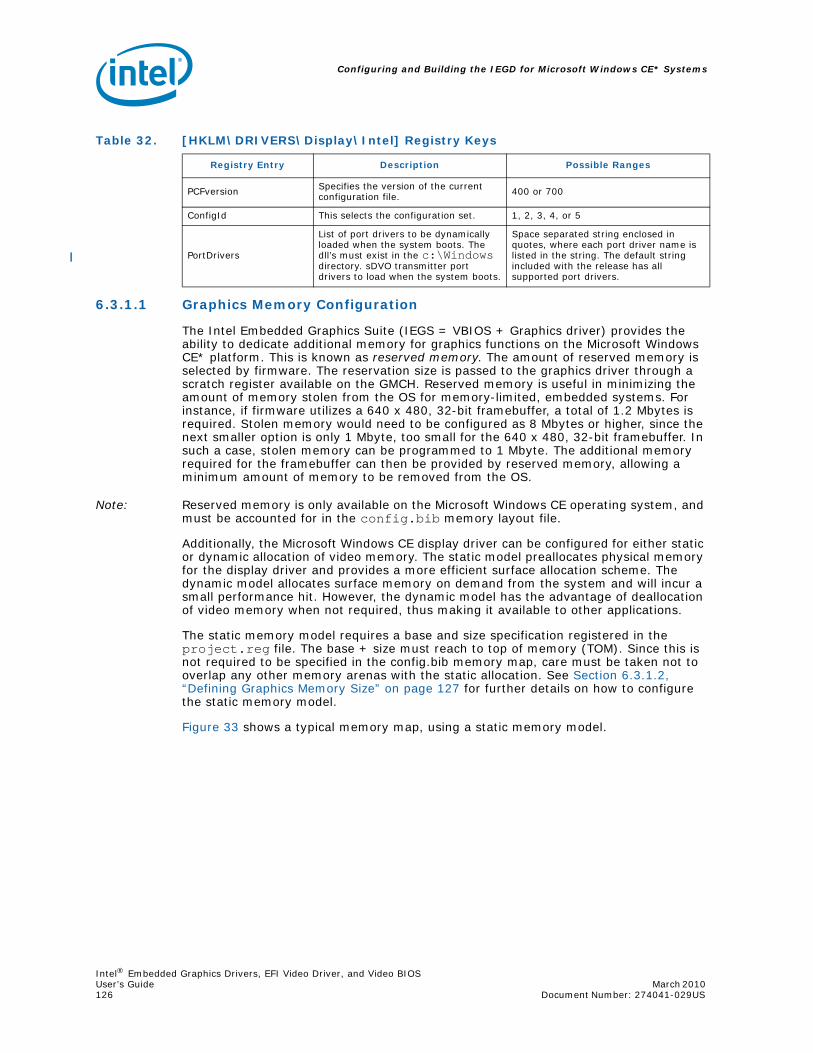
Configuring and Building the IEGD for Microsoft Windows CE* Systems
Intel® Embedded Graphics Drivers, EFI Video Driver, and Video BIOSUser’s Guide March 2010 126 Document Number: 274041-029US
6.3.1.1 Graphics Memory Configuration
The Intel Embedded Graphics Suite (IEGS = VBIOS + Graphics driver) provides the ability to dedicate additional memory for graphics functions on the Microsoft Windows CE* platform. This is known as reserved memory. The amount of reserved memory is selected by firmware. The reservation size is passed to the graphics driver through a scratch register available on the GMCH. Reserved memory is useful in minimizing the amount of memory stolen from the OS for memory-limited, embedded systems. For instance, if firmware utilizes a 640 x 480, 32-bit framebuffer, a total of 1.2 Mbytes is required. Stolen memory would need to be configured as 8 Mbytes or higher, since the next smaller option is only 1 Mbyte, too small for the 640 x 480, 32-bit framebuffer. In such a case, stolen memory can be programmed to 1 Mbyte. The additional memory required for the framebuffer can then be provided by reserved memory, allowing a minimum amount of memory to be removed from the OS.
Note: Reserved memory is only available on the Microsoft Windows CE operating system, and must be accounted for in the config.bib memory layout file.
Additionally, the Microsoft Windows CE display driver can be configured for either static or dynamic allocation of video memory. The static model preallocates physical memory for the display driver and provides a more efficient surface allocation scheme. The dynamic model allocates surface memory on demand from the system and will incur a small performance hit. However, the dynamic model has the advantage of deallocation of video memory when not required, thus making it available to other applications.
The static memory model requires a base and size specification registered in the project.reg file. The base + size must reach to top of memory (TOM). Since this is not required to be specified in the config.bib memory map, care must be taken not to overlap any other memory arenas with the static allocation. See Section 6.3.1.2, “Defining Graphics Memory Size” on page 127 for further details on how to configure the static memory model.
Figure 33 shows a typical memory map, using a static memory model.
Table 32. [HKLM\DRIVERS\Display\Intel] Registry Keys
Registry Entry Description Possible Ranges
PCFversion Specifies the version of the current configuration file. 400 or 700
ConfigId This selects the configuration set. 1, 2, 3, 4, or 5
PortDrivers
List of port drivers to be dynamically loaded when the system boots. The dll’s must exist in the c:\Windows directory. sDVO transmitter port drivers to load when the system boots.
Space separated string enclosed in quotes, where each port driver name is listed in the string. The default string included with the release has all supported port drivers.
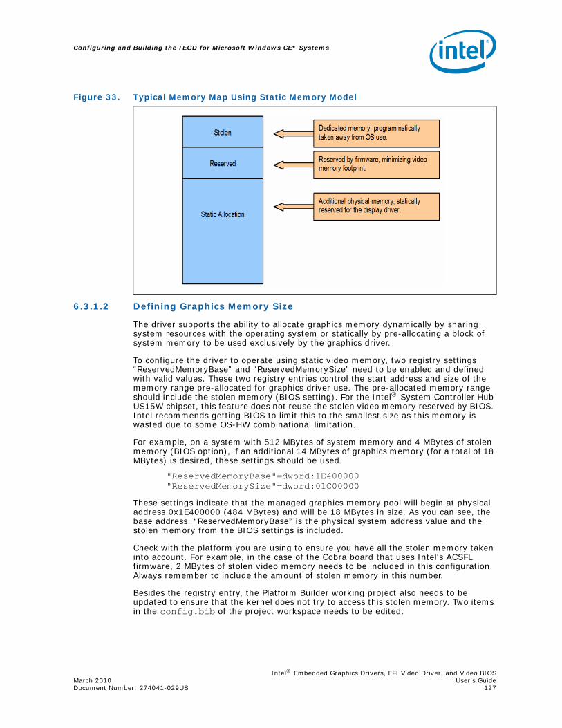
Intel® Embedded Graphics Drivers, EFI Video Driver, and Video BIOSMarch 2010 User’s GuideDocument Number: 274041-029US 127
Configuring and Building the IEGD for Microsoft Windows CE* Systems
6.3.1.2 Defining Graphics Memory Size
The driver supports the ability to allocate graphics memory dynamically by sharing system resources with the operating system or statically by pre-allocating a block of system memory to be used exclusively by the graphics driver.
To configure the driver to operate using static video memory, two registry settings “ReservedMemoryBase” and “ReservedMemorySize” need to be enabled and defined with valid values. These two registry entries control the start address and size of the memory range pre-allocated for graphics driver use. The pre-allocated memory range should include the stolen memory (BIOS setting). For the Intel® System Controller Hub US15W chipset, this feature does not reuse the stolen video memory reserved by BIOS. Intel recommends getting BIOS to limit this to the smallest size as this memory is wasted due to some OS-HW combinational limitation.
For example, on a system with 512 MBytes of system memory and 4 MBytes of stolen memory (BIOS option), if an additional 14 MBytes of graphics memory (for a total of 18 MBytes) is desired, these settings should be used.
"ReservedMemoryBase"=dword:1E400000"ReservedMemorySize"=dword:01C00000
These settings indicate that the managed graphics memory pool will begin at physical address 0x1E400000 (484 MBytes) and will be 18 MBytes in size. As you can see, the base address, “ReservedMemoryBase” is the physical system address value and the stolen memory from the BIOS settings is included.
Check with the platform you are using to ensure you have all the stolen memory taken into account. For example, in the case of the Cobra board that uses Intel's ACSFL firmware, 2 MBytes of stolen video memory needs to be included in this configuration. Always remember to include the amount of stolen memory in this number.
Besides the registry entry, the Platform Builder working project also needs to be updated to ensure that the kernel does not try to access this stolen memory. Two items in the config.bib of the project workspace needs to be edited.
Figure 33. Typical Memory Map Using Static Memory Model
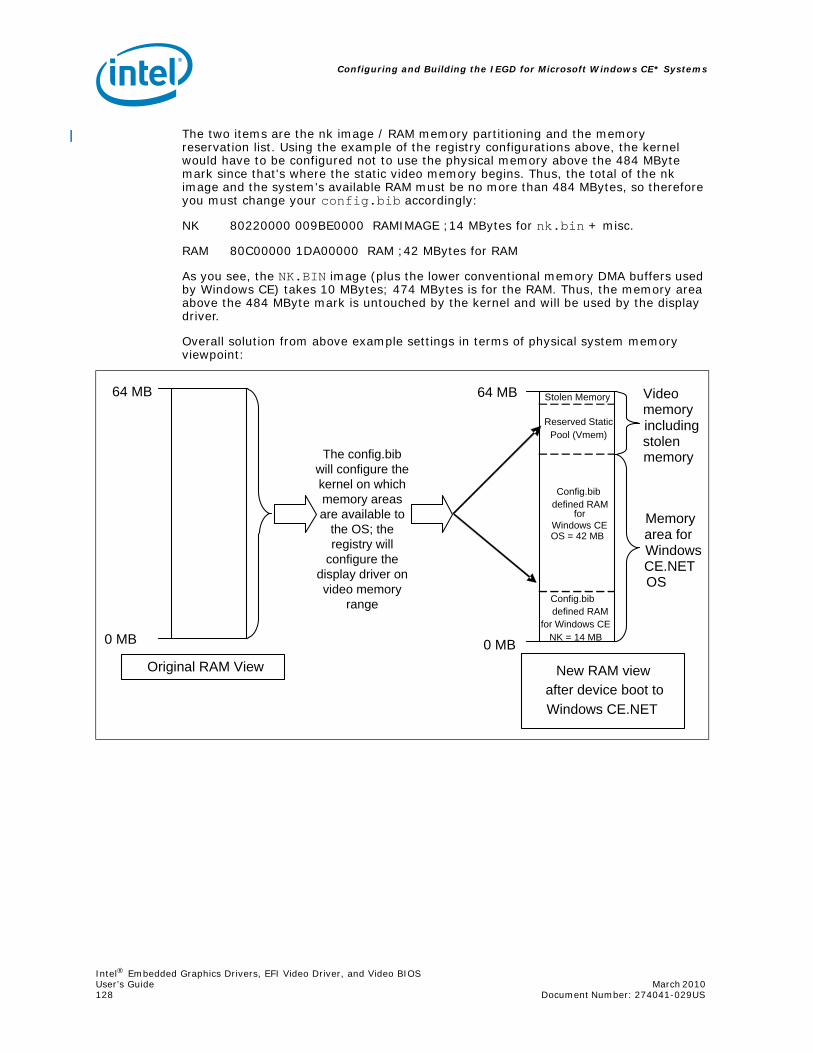
Configuring and Building the IEGD for Microsoft Windows CE* Systems
Intel® Embedded Graphics Drivers, EFI Video Driver, and Video BIOSUser’s Guide March 2010 128 Document Number: 274041-029US
The two items are the nk image / RAM memory partitioning and the memory reservation list. Using the example of the registry configurations above, the kernel would have to be configured not to use the physical memory above the 484 MByte mark since that's where the static video memory begins. Thus, the total of the nk image and the system's available RAM must be no more than 484 MBytes, so therefore you must change your config.bib accordingly:
NK 80220000 009BE0000 RAMIMAGE ;14 MBytes for nk.bin + misc.
RAM 80C00000 1DA00000 RAM ;42 MBytes for RAM
As you see, the NK.BIN image (plus the lower conventional memory DMA buffers used by Windows CE) takes 10 MBytes; 474 MBytes is for the RAM. Thus, the memory area above the 484 MByte mark is untouched by the kernel and will be used by the display driver.
Overall solution from above example settings in terms of physical system memory viewpoint:
64 MB
0 MB
Original RAM View
The config.bib will configure the kernel on which memory areas are available to
the OS; the registry will
configure the display driver on video memory
range
New RAM view after device boot to Windows CE.NET
Stolen Memory
Reserved Static Pool (Vmem)
Config.bib defined RAM
for Windows CEOS = 42 MB
Config.bib defined RAM
for Windows CE NK = 14 MB
64 MB
0 MB
Video memory including stolen memory
Memory area for Windows CE.NET OS
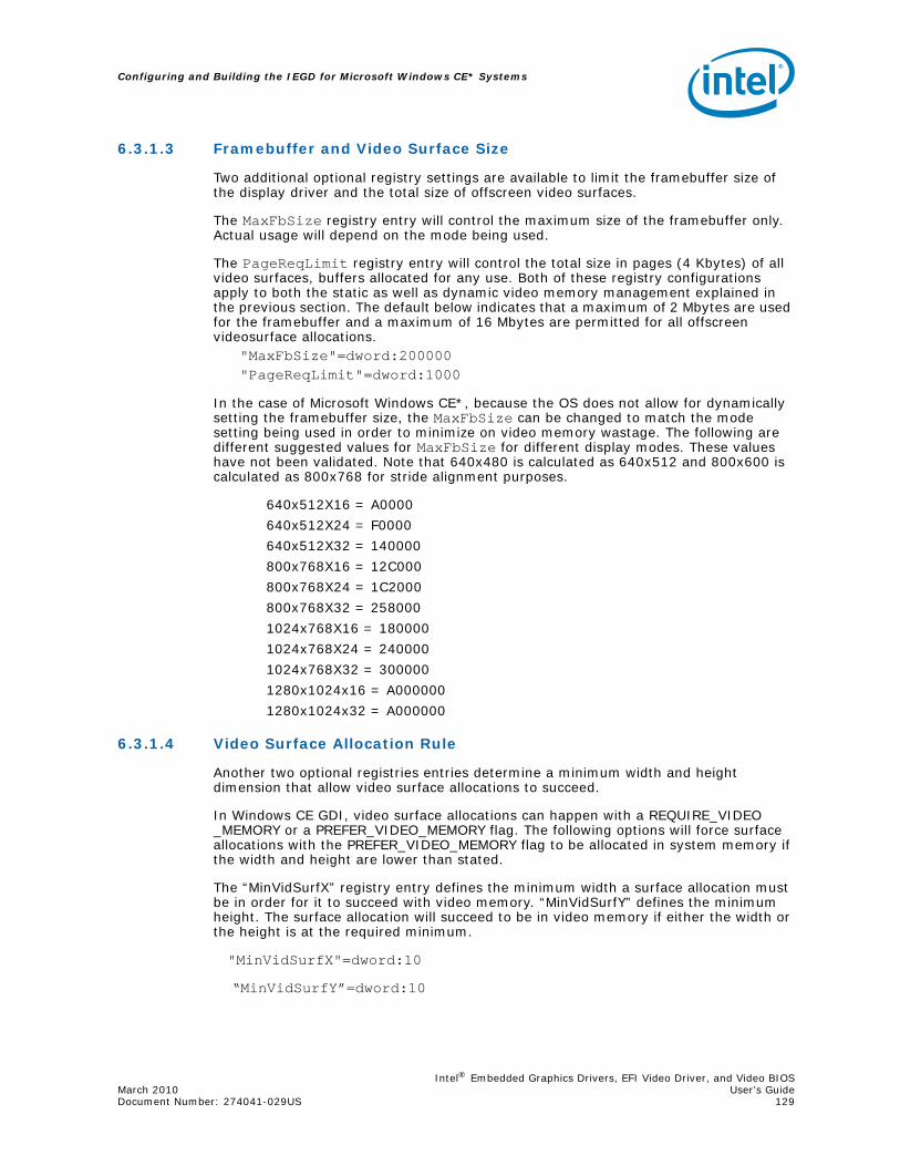
Intel® Embedded Graphics Drivers, EFI Video Driver, and Video BIOSMarch 2010 User’s GuideDocument Number: 274041-029US 129
Configuring and Building the IEGD for Microsoft Windows CE* Systems
6.3.1.3 Framebuffer and Video Surface Size
Two additional optional registry settings are available to limit the framebuffer size of the display driver and the total size of offscreen video surfaces.
The MaxFbSize registry entry will control the maximum size of the framebuffer only. Actual usage will depend on the mode being used.
The PageReqLimit registry entry will control the total size in pages (4 Kbytes) of all video surfaces, buffers allocated for any use. Both of these registry configurations apply to both the static as well as dynamic video memory management explained in the previous section. The default below indicates that a maximum of 2 Mbytes are used for the framebuffer and a maximum of 16 Mbytes are permitted for all offscreen videosurface allocations.
"MaxFbSize"=dword:200000"PageReqLimit"=dword:1000
In the case of Microsoft Windows CE*, because the OS does not allow for dynamically setting the framebuffer size, the MaxFbSize can be changed to match the mode setting being used in order to minimize on video memory wastage. The following are different suggested values for MaxFbSize for different display modes. These values have not been validated. Note that 640x480 is calculated as 640x512 and 800x600 is calculated as 800x768 for stride alignment purposes.
640x512X16 = A0000
640x512X24 = F0000
640x512X32 = 140000
800x768X16 = 12C000
800x768X24 = 1C2000
800x768X32 = 258000
1024x768X16 = 180000
1024x768X24 = 240000
1024x768X32 = 300000
1280x1024x16 = A000000
1280x1024x32 = A000000
6.3.1.4 Video Surface Allocation Rule
Another two optional registries entries determine a minimum width and height dimension that allow video surface allocations to succeed.
In Windows CE GDI, video surface allocations can happen with a REQUIRE_VIDEO _MEMORY or a PREFER_VIDEO_MEMORY flag. The following options will force surface allocations with the PREFER_VIDEO_MEMORY flag to be allocated in system memory if the width and height are lower than stated.
The “MinVidSurfX” registry entry defines the minimum width a surface allocation must be in order for it to succeed with video memory. “MinVidSurfY” defines the minimum height. The surface allocation will succeed to be in video memory if either the width or the height is at the required minimum.
"MinVidSurfX"=dword:10
“MinVidSurfY”=dword:10

Configuring and Building the IEGD for Microsoft Windows CE* Systems
Intel® Embedded Graphics Drivers, EFI Video Driver, and Video BIOSUser’s Guide March 2010 130 Document Number: 274041-029US
In this example, surfaces allocated with the PREFER_VIDEO_MEMORY where the width and height are both less than 16 pixels are forced to be in system memory.
This option increases performance of the display device as smaller video images, such as icons, would be kept in system memory and only blitted onto the visible frame buffer when they are needed. This would ensure the display device is used optimally for larger video surfaces where acceleration makes sense.
6.3.1.5 System to Video Stretch Blit
System to Video Memory stretch blits are not natively supported on Intel GMCH devices. This feature allows you to enable a soft copy of system surfaces to video surfaces in order to conduct an accelerated stretch blit. The advantage of this is that the stretch blit then utilizes the blend engine and hardware filtering can be applied. The filtering options are listed in Section 6.3.2.
A value of 1 for the “SysToVidStretch” enables system to video stretch blits, as described above, while a value of 0, disables this feature and forwards all system to video stretch blits to the emulator provided by the operating system.
[HKEY_LOCAL_MACHINE\Drivers\Display\Intel\ALL\1\General]"SysToVidStretch"=dword:0
6.3.1.6 iegd.reg File Backward Compatibility
The Intel Embedded Graphics Driver expects a configuration file in the PCFVersion 700 format. However, the driver will maintain backward support with version 4.0. This support is implemented through the PcfVersion key as shown below:
[HKEY_LOCAL_MACHINE\Drivers\Display\Intel\ALL\1\General]"PcfVersion"=dword:400
The IEGD uses this key to determine the format of the configuration file. When this key is present, IEGD parses the configuration file using the format specified by the key (400 or 700). If this key is not present, then IEGD assumes 4.0 format.
6.3.2 Configuration Sets
The Intel® Embedded Graphics Drivers allows multiple configuration sets for OEMs who want to use the same iegd.reg file across different platforms. There can be up to 16 instances of configurations. The registry key described in the previous section, ConfigId, ensures the display driver selects the right instance. Each instance may contain multiple groups of per-config and per-config+per-port platform customizations.
The configuration sets are defined in the registry tree as
[HKEY_LOCAL_MACHINE\Drivers\Display\Intel\<platform>\<config id>],
Where <config id> is the configuration number. The “ConfigID” key described in the previous section selects the active configuration set.
6.3.3 General Configuration
Registry keys described in this section can be found in [HKEY_LOCAL_MACHINE\Drivers\Display\Intel\<platform>\<config id>\], where <config id> is the configuration number, and where <platform> is one of the following: ALL, Q45/G41/G45, US15W/US15WP/WPT, GM45/GL40/GS45, Q35, GLE960/GME965, Q965, 945G, 945GME/945GSE, 945GSE, 915GV, 915GME, and 910GMLE. The driver first attempts to find the configuration or platform on which it is booted, but if the configuration for that platform is not present, the driver uses the ALL platform setting.

Intel® Embedded Graphics Drivers, EFI Video Driver, and Video BIOSMarch 2010 User’s GuideDocument Number: 274041-029US 131
Configuring and Building the IEGD for Microsoft Windows CE* Systems
Table 33. [HKLM\Drivers\Display\Intel\<platform>\<config id>\]Registry Keys (Sheet 1 of 2)
Registry Entry Description Possible Ranges
Width Width of the display
Width and Height must be expressed as hexidecimal values. For example:1024 x 768: 400 x 300800 x 600: 320 x 258640 x 480: 280 x 1E0
Height Height of the display See above.
Depth Color depth in bpp (bits per pixel)
Depth must be expressed as a hexidecimal number and must be one of the following values:8bpp: 816bpp: 1024bpp: 1832bpp: 20(Note that the Intel 915 chipsets do not support 24 bpp.)
Refresh The refresh rate of the display.
Refresh rate must be in hex:60 : 3c70 : 4675 : 4b85 : 55etc...
This value can be any valid refresh rate as long as the display port supports it. A refresh of '0' takes the first refresh that matches width, height and depth.
NO_D3D Specify whether to enable D3D.0 = Enable D3D1 = Disable D3DDefault is 0.
ReservedMemoryBaseReservedMemorySize
Video memory can be statically reserved or dynamically allocated on demand. If both ReservedMemoryBase and ReservedMemorySize are non-zero, then Video memory allocation utilizes the static model.
The ReservedMemoryBase plus the ReservedMemorySize must extend to the TOM (Top Of Memory) and not conflict with other reserved memory arenas in config.bib. Default for both base and size is zero, indicating a dynamic allocation model.Default behavior disables static memory model.
MaxFbSize
Maximum size of the expected framebuffer. By providing this hint, the display driver can more efficiently organize GART memory, leading to a smaller video memory consumption.
Must be greater than or equal to the expected size of framebuffer. Units are in bytes. Specifying zero causes the default framebuffer reservation sizing.Default:All other chipsets: 16 Mbytes
MinVidSurfXMinVidSurfY
In pixels, the minimum width and height of surfaces in order to be acceptable for allocation in Video memory. Due to hardware restrictions that optimize memory access, it is advisable to reserve video memory for larger surfaces and allow GDI and DirectDraw* to allocate small surfaces from system memory.
No limitations. Suggested values for both width and height are 10. Default value for both width and height is 1.Default:MinVidSurfX = 1MinVidSurfY = 1

Configuring and Building the IEGD for Microsoft Windows CE* Systems
Intel® Embedded Graphics Drivers, EFI Video Driver, and Video BIOSUser’s Guide March 2010 132 Document Number: 274041-029US
SysToVidStretch
Enables system-to-video memory stretch blit operations to take advantage of hardware-accelerated filtering. Normally, it is more efficient to allow GDI to conduct system-to-video stretch blits, but the default filtering used by GDI is Nearest.
0 = Disabled1 = EnabledDefault: 0
BlendFilterProvides selection of hardware-accelerated filtering methods for stretch blit operations.
0 = Nearest1 = Bilinear2 = AnisotropicDefault: 2
TearFB
If enabled, all blit operations to the framebuffer are synchronized with video sync to eliminate any visible tearing or flickering on the display screen. Disabling this feature achieves a performance gain.
0 = Disabled, tearing allowed1 = Enabled, no visible tearingDefault: 1
OverlayDualVext
Provides selection for enabling two hardware overlay planes (one for each screen) to display independent video stream on each overlay plane. This selection only applicable in Vertical Extended Mode on Intel® System Controller Hub US15W. Note that the hardware overlay plane for each display locks on that screen; the overlay fails to display if it is crossed into the wrong screen.
0 = Disabled1 = EnabledDefault: 0
DisplayConfig
The “DisplayConfig” key sets the display configuration to be in Single, Twin, Clone, or Vertical Extended modes. (Unlike Microsoft Windows* XP, Microsoft Windows CE* does not support Extended mode). It does not, however, dictate what type of display ports will be used.
1 (single), 2 (clone), 4 (twin), 5 (vertical extended)
DisplayDetect
The “DisplayDetect” key allows the user to enable a display port only if a display device is connected. Displays without EDID will not be detected.
0 = disable1 = enableDefault: 0
PortOrderThe PortOrder setting ensures the correct display port types are used based on user selection.
See Section 6.3.3.1.
Table 33. [HKLM\Drivers\Display\Intel\<platform>\<config id>\]Registry Keys (Sheet 2 of 2)
Registry Entry Description Possible Ranges

Intel® Embedded Graphics Drivers, EFI Video Driver, and Video BIOSMarch 2010 User’s GuideDocument Number: 274041-029US 133
Configuring and Building the IEGD for Microsoft Windows CE* Systems
6.3.3.1 PortOrder Information
PortOrder specifies the actual ports that are used for the Primary and Secondary display. As shown in the table below, the port numbers are slightly different among the supported chipsets.
The driver attempts to use the ports in the order specified by “PortOrder”. For example, “PortOrder” = “5420” will assign the analog port to the primary display and the LVDS port to the secondary display (if any), assuming all the ports are present and detected. Suppose port “5” is not present, in that case the driver tries to assign the next port (4, in this case) in line to the primary display, resulting LVDS port for primary and sDVO B port for secondary.
Setting PortOrder to “00000” causes the driver to use default internal settings.
*************[HKEY_LOCAL_MACHINE\Drivers\Display\Intel\ALL\1\General];-------------------------------------; Select Port Order;-------------------------------------“PortOrder”=“54320”
; PortOrder specifies the actual of port; that will be taken for the Primary /; Secondary ports if there are duplicates; of the same type. For example, if both ; Primary and Secondary are digital, then ; port order will which sDVO ports will be; first and second. The section below gives; the port order numbers for various chipsets.; Specify value “0000” to use default settings.; On i915 chipsets:; ================================; 1 - Integrated TV Encoder; 2 - sDVO B port/RGBA port; 3 - sDVO C port; 4 - Internal LVDS port; 5 - Analog port;
Table 34. PortOrder Information
Port Number Chipsets
1 Integrated TV Encoder
2 sDVO B Port/RGBA Port
3 sDVO C Port
4 Internal LVDS Port
5 Analog Port
Configuring and Building the IEGD for Microsoft Windows CE* Systems
Intel® Embedded Graphics Drivers, EFI Video Driver, and Video BIOSUser’s Guide March 2010 134 Document Number: 274041-029US
6.3.3.2 Vertical Extended Mode
The Windows CE* IEGD driver supports Vertical Extended display mode, which is one large framebuffer that extends across two displays by doubling the height of resolution. The top half of the framebuffer is on the first pipe and the bottom half is on the second pipe. The Windows CE operating system is unaware of the two displays. This feature is supported only on the dual-pipelined chipsets, which is every supported platform stated in Section 6.2.1.
This feature is enabled through the DisplayConfig key in the project.reg file. The resolution, bit depth, and refresh rates of both displays must be the same. Vertical and horizontal panning are not supported. DirectDraw is supported on both pipes, but DirectDraw 3D must be disabled when Vertical Extended Display mode is enabled.
6.3.4 Per Port Platform Customization
The Intel Embedded Graphics Drivers provide what is considered the most useful tools to the embedded market — per port platform customizations. This includes the following:
• Defining custom DTD panel timings: PixelClock, HorzActive, HorzSync etc...
• Customized GPIO pin selection for I2C and DDC communication with sDVO encoders and panels.:I2cPin, I2cDab, I2cSpeed etc...
• Flat Panel width and height limitations and power and/or backlight control mechanisms:BkltMethod, BkltT1, BkltT2, GpioPinVdd etc...
• Port driver specific attribute settings for initialization at boot time.: Brightness, Contrast, H-Position etc...
All of the above can be set for each individual port depending on the maximum number of ports the chipset supports. Also, you can have multiple instances of these configurations to allow different settings per configuration.
The usage model for this per-config, per-port platform customizations follows after the same options available in the INF registry settings for the Intel Embedded Graphics Drivers for Microsoft Windows XP*. Please see Figure 6.3.7, “Sample iegd.reg File” on page 138 or to the provided registry sample file in the IEGD Windows CE* driver package for examples. The following sections provide information on these configurations.
6.3.4.1 Per Port Customization — General Port Configuration
This section describes port-specific general configuration options. These options are located under [HKEY_LOCAL_MACHINE\Drivers\Display\Intel\ALL\1\Port\1\General]
• EdidThis boolean key enables (set to 1) or disables (set to 0) the EdidAvail and EdidNotAvail keys.
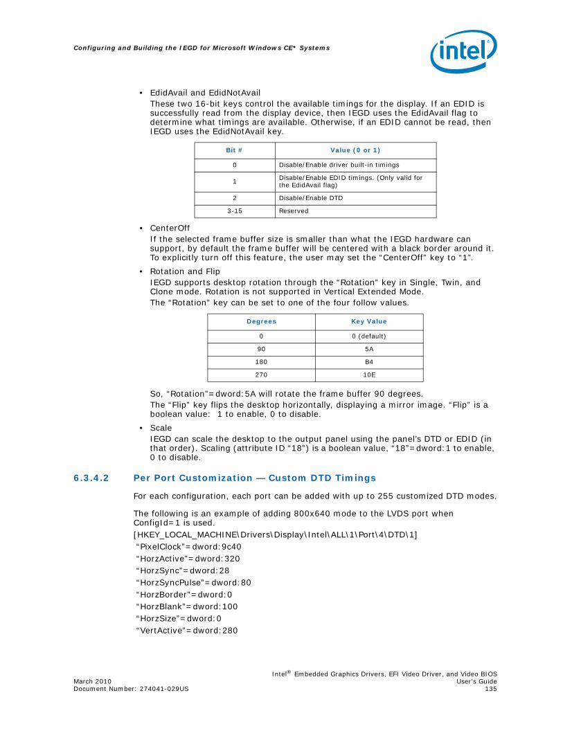
Intel® Embedded Graphics Drivers, EFI Video Driver, and Video BIOSMarch 2010 User’s GuideDocument Number: 274041-029US 135
Configuring and Building the IEGD for Microsoft Windows CE* Systems
• EdidAvail and EdidNotAvailThese two 16-bit keys control the available timings for the display. If an EDID is successfully read from the display device, then IEGD uses the EdidAvail flag to determine what timings are available. Otherwise, if an EDID cannot be read, then IEGD uses the EdidNotAvail key.
• CenterOffIf the selected frame buffer size is smaller than what the IEGD hardware can support, by default the frame buffer will be centered with a black border around it. To explicitly turn off this feature, the user may set the “CenterOff” key to “1”.
• Rotation and FlipIEGD supports desktop rotation through the “Rotation” key in Single, Twin, and Clone mode. Rotation is not supported in Vertical Extended Mode.The “Rotation” key can be set to one of the four follow values.
So, “Rotation”=dword:5A will rotate the frame buffer 90 degrees.The “Flip” key flips the desktop horizontally, displaying a mirror image. “Flip” is a boolean value: 1 to enable, 0 to disable.
• ScaleIEGD can scale the desktop to the output panel using the panel’s DTD or EDID (in that order). Scaling (attribute ID “18”) is a boolean value, “18”=dword:1 to enable, 0 to disable.
6.3.4.2 Per Port Customization — Custom DTD Timings
For each configuration, each port can be added with up to 255 customized DTD modes.
The following is an example of adding 800x640 mode to the LVDS port when ConfigId=1 is used.[HKEY_LOCAL_MACHINE\Drivers\Display\Intel\ALL\1\Port\4\DTD\1] “PixelClock”=dword:9c40 “HorzActive”=dword:320 “HorzSync”=dword:28 “HorzSyncPulse”=dword:80 “HorzBorder”=dword:0 “HorzBlank”=dword:100 “HorzSize”=dword:0 “VertActive”=dword:280
Bit # Value (0 or 1)
0 Disable/Enable driver built-in timings
1 Disable/Enable EDID timings. (Only valid for the EdidAvail flag)
2 Disable/Enable DTD
3-15 Reserved
Degrees Key Value
0 0 (default)
90 5A
180 B4
270 10E

Configuring and Building the IEGD for Microsoft Windows CE* Systems
Intel® Embedded Graphics Drivers, EFI Video Driver, and Video BIOSUser’s Guide March 2010 136 Document Number: 274041-029US
“VertSync”=dword:1 “VertSyncPulse”=dword:4 “VertBorder”=dword:0 “VertBlank”=dword:1c “VertSize”=dword:0 “Flags”=dword:1e
6.3.4.3 Per Port Customization — Custom Flat Panel Controls
Similarly, the flat panel native resolution and power and backlight sequencing controls can also be configured here.;[HKEY_LOCAL_MACHINE\Drivers\Display\Intel\ALL\1\Port\1\FPInfo]
; “BkltMethod”=dword:0; “BkltT1”=dword:0; “BkltT2”=dword:0; “BkltT3”=dword:0; “BkltT4”=dword:0; “BkltT5”=dword:0; “GpioPinVdd”=dword:0; “GpioPinVee”=dword:0; “GpioPinBklt”=dword:0; “BkltEnable”=dword:0; “UseGMCHClockPin”=dword:0; “UseGMCHDataPin”=dword:0
Note: For Per-Config, Per-Port configuration, the subkey path includes the correct “Config” and “Port” numbers
6.3.4.4 Per Port Customization — Attribute Initialization
Attributes are also per config and per port. However, the actual keys are dependant on the port driver being used. Below are examples of registry keys associated with initializing attributes for the Chrontel Port Driver.
For complete information on port driver attributes, refer to Appendix B.
Note: For Per-Config, Per-Port configuration, the subkey path includes the correct “Config” and “Port” numbers.
The following example sets the port driver attributes using the attribute IDs. Please see Section B.2.4, “Internal TV Out Port Driver Attributes (Mobile chipsets only)” on page 217 for a list of attribute IDs and their meanings.
[HKEY_LOCAL_MACHINE\Drivers\Display\Intel\ALL\1\Port\1\Attr]
“0”=dword:32
“1”=dword:4
“3”=dword:1
“8”=dword:1
“12”=dword:0
“14”=dword:1
“19”=dword:1
Intel® Embedded Graphics Drivers, EFI Video Driver, and Video BIOSMarch 2010 User’s GuideDocument Number: 274041-029US 137
Configuring and Building the IEGD for Microsoft Windows CE* Systems
6.3.5 Miscellaneous Configuration Options
This section covers registry settings not in [HKEY_LOCAL_MACHINE\Drivers\Display\Intel].
6.3.5.1 Text Anti-Aliasing
The Microsoft Windows CE* driver supports text anti-aliasing. To switch it on, add these registry settings:[HKEY_LOCAL_MACHINE\System\GDI\Fontsmoothing][HKEY_LOCAL_MACHINE\System\GDI]
"ForceGRAY16"=dword:1
Note: Text Anti-Aliasing should always be turned on when using a TV display device.
6.3.6 Direct3D* Mobile Support
IEGD v10.3.1 supports Direct3D* Mobile on Windows CE* 5.0 and 6.0. Users need to ensure that their Windows CE target machine platform workspace has been included with D3D Mobile support. This is done by simply dragging the D3D Mobile component from the catalog view to the workspace in Windows CE 5.0 or turning it on via the check box in Windows CE 6.0.
Also, the new IEGD D3D mobile driver binary, “iegd3dg3.dll” (part of the IEGD driver release for Windows CE 5.0 and 6.0) needs to be included in the workspace image. Add this binary into the “.BIB” configuration file of the target platform workspace (see Figure 32):
iegd3dg3.dll <specify_path_here>\iegd3dg3.dll NK
No other IEGD registry configuration is necessary for this feature to work.
Note: The IEGD Windows CE D3D Mobile feature requires more memory at runtime:
• For Windows CE 5.0, it is recommended that 64 Mbytes is configured via Platform Builder (go to the Platform menu, choose Settings, and choose the Build Options tab. Ensure the option labeled “Run-time Image Can be Larger than 32 Mbytes (IMGRAM64=1)” is checked).
• For Windows CE 6.0, depending on the number of components built into the target platform workspace, the amount of memory could be significantly more, due in part to the new kernel memory architecture adopted by the OS (assuming all multimedia components are built-in). It is recommended that 84 Mbytes of memory be configured for the target machine workspace image. Refer to the following Microsoft URL for information on how configure more than 64 Mbytes on Windows CE 6.0:http://msdn2.microsoft.com/en-us/library/aa909457.aspx
See also the “Sample iegd.reg File”.

Configuring and Building the IEGD for Microsoft Windows CE* Systems
Intel® Embedded Graphics Drivers, EFI Video Driver, and Video BIOSUser’s Guide March 2010 138 Document Number: 274041-029US
6.3.7 Sample iegd.reg File
;****************** BEGIN INTEL DISPLAY DRIVER REGISTRY ENTRY *****************;******************************************************************************;*----------------------------------------------------------------------------;* Copyright (c) Intel Corporation (2002 - 2009).;*;* The source code contained or described herein and all documents;* related to the source code ("Material") are owned by Intel;* Corporation or its suppliers or licensors. Title to the Material;* remains with Intel Corporation or it suppliers and licensors. The;* Material contains trade secrets and proprietary and confidential;* information of Intel or its suppliers and licensors. The Material is;* protected by worldwide copyright and trade secret laws and;* treaty provisions. No part of the Material may be used, copied,;* reproduced, modified, published, uploaded, posted, transmitted,;* distributed, or disclosed in any way without Intels prior express;* written permission.;*;* No license under any patent, copyright, trade secret or other;* intellectual property right is granted to or conferred upon you by;* disclosure or delivery of the Materials, either expressly, by;* implication, inducement, estoppel or otherwise. Any license;* under such intellectual property rights must be express;* and approved by Intel in writing.;*----------------------------------------------------------------------------[HKEY_LOCAL_MACHINE\Drivers\BuiltIn\PCI\Template\IEGD] "Dll"="isr_iegd.dll" "Class"=dword:03 "SubClass"=dword:00 "ProgIF"=dword:00 "VendorID"=multi_sz:"8086" "DeviceID"=multi_sz:"8108" ; US15 is the only chipset supporting interrupts "Prefix"="IGD" "IsrDll"="isr_iegd.dll" "IsrHandler"="isr_handler" ;*----------------------------------------------------------------------------[HKEY_LOCAL_MACHINE\System\GDI\Drivers] "Display"="ddi_iegd.dll" [HKEY_LOCAL_MACHINE\System\D3DM\Drivers] "RemoteHook"="ddi_iegd.dll" [HKEY_LOCAL_MACHINE\System\GDIM\Drivers] "D3DMOverride"="ddi_iegd.dll";******************************************************************************; The Following Sections Provide; General Driver-Wide Registry Settings;******************************************************************************[HKEY_LOCAL_MACHINE\Drivers\Display\Intel];------------------------------------------------------------------------------; Following registry entry for; pcf version used; 700 : IEGD version;------------------------------------------------------------------------------"PcfVersion"=dword:700

Intel® Embedded Graphics Drivers, EFI Video Driver, and Video BIOSMarch 2010 User’s GuideDocument Number: 274041-029US 139
Configuring and Building the IEGD for Microsoft Windows CE* Systems
;------------------------------------------------------------------------------; This value dictates the configuration to select for Per-Port settings from; port specific regsitry. The settings mirror Windows XP IEGD drivers; implementation. Refer to the User’s Guide for details.;------------------------------------------------------------------------------"ConfigId"=dword:1;------------------------------------------------------------------------------; Provide a list of port drivers to attempt to load upon boot time;------------------------------------------------------------------------------"PortDrivers"="analog ch7009 ch7017 fs454 lvds ns2501 ns387 sii164 ti410 th164 sdvo hdmi tv";******************************************************************************; The Following Sections Provide Per-Config configuration. The Platform string in ; the path can be “ALL” for all platforms, or any of the following for ; platform-specific configurations:; Q35, GM965, Q965, 946GZ, 945G, 945GM, 915GV, and 915GM;******************************************************************************[HKEY_LOCAL_MACHINE\Drivers\Display\Intel\ALL\1\General];------------------------------------------------------------------------------; Following registry entries for display settings:resolution, bit depth and; refresh rate;; Width & Height values must be hex, for example; 1400x1050 : 578h x 41Ah; 1280x1024 : 500h x 400h; 1024x768 : 400h x 300h; 800x600 : 320h x 258h; 640x480 : 280h x 1E0h; etc...;; In vertical extented mode, height is doubled; 640x960 : 280h x 3c0; 800x600 : 320h x 4b0h; etc...;;------------------------------------------------------------------------------"Width"=dword:320"Height"=dword:258;------------------------------------------------------------------------------; Bit depth must be one of:; 8bpp : 8; 16bpp : 10; 24bpp : 18; 32bpp : 20; (all current IEGD 6.0 & above chipsets do not support 24 bpp);------------------------------------------------------------------------------"Depth"=dword:20;------------------------------------------------------------------------------; Refresh rate must be in hex:; 60 : 3cIntel® Embedded Graphics Drivers and Video BIOS v10.3.1User’s Guide March 2010Document Number: 274041-029USInstalling and Configuring Microsoft Windows CE Drivers; 70 : 46; 75 : 4b
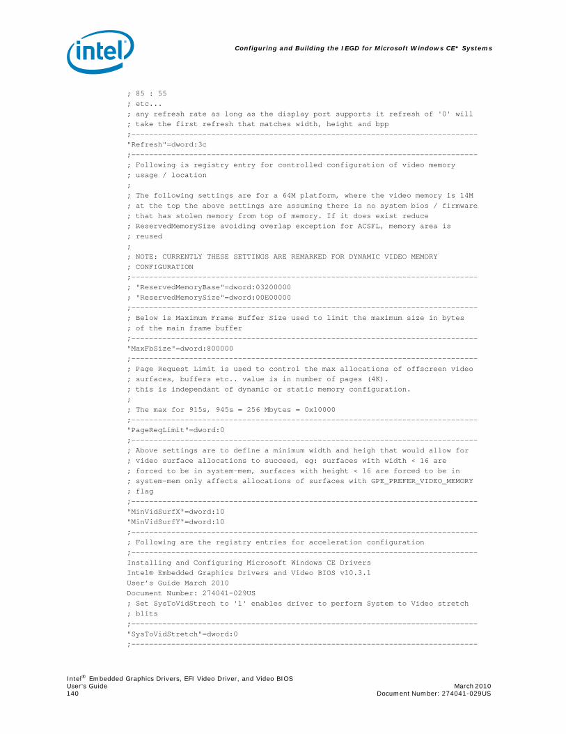
Configuring and Building the IEGD for Microsoft Windows CE* Systems
Intel® Embedded Graphics Drivers, EFI Video Driver, and Video BIOSUser’s Guide March 2010 140 Document Number: 274041-029US
; 85 : 55; etc...; any refresh rate as long as the display port supports it refresh of '0' will; take the first refresh that matches width, height and bpp;------------------------------------------------------------------------------"Refresh"=dword:3c;------------------------------------------------------------------------------; Following is registry entry for controlled configuration of video memory; usage / location;; The following settings are for a 64M platform, where the video memory is 14M; at the top the above settings are assuming there is no system bios / firmware; that has stolen memory from top of memory. If it does exist reduce; ReservedMemorySize avoiding overlap exception for ACSFL, memory area is; reused;; NOTE: CURRENTLY THESE SETTINGS ARE REMARKED FOR DYNAMIC VIDEO MEMORY; CONFIGURATION;------------------------------------------------------------------------------; "ReservedMemoryBase"=dword:03200000; "ReservedMemorySize"=dword:00E00000;------------------------------------------------------------------------------; Below is Maximum Frame Buffer Size used to limit the maximum size in bytes; of the main frame buffer;------------------------------------------------------------------------------"MaxFbSize"=dword:800000;------------------------------------------------------------------------------; Page Request Limit is used to control the max allocations of offscreen video; surfaces, buffers etc.. value is in number of pages (4K).; this is independant of dynamic or static memory configuration.;; The max for 915s, 945s = 256 Mbytes = 0x10000;------------------------------------------------------------------------------"PageReqLimit"=dword:0;------------------------------------------------------------------------------; Above settings are to define a minimum width and heigh that would allow for; video surface allocations to succeed, eg: surfaces with width < 16 are; forced to be in system-mem, surfaces with height < 16 are forced to be in; system-mem only affects allocations of surfaces with GPE_PREFER_VIDEO_MEMORY; flag;------------------------------------------------------------------------------"MinVidSurfX"=dword:10"MinVidSurfY"=dword:10;------------------------------------------------------------------------------; Following are the registry entries for acceleration configuration;------------------------------------------------------------------------------Installing and Configuring Microsoft Windows CE DriversIntel® Embedded Graphics Drivers and Video BIOS v10.3.1User’s Guide March 2010Document Number: 274041-029US; Set SysToVidStrech to '1' enables driver to perform System to Video stretch; blits;------------------------------------------------------------------------------"SysToVidStretch"=dword:0;------------------------------------------------------------------------------
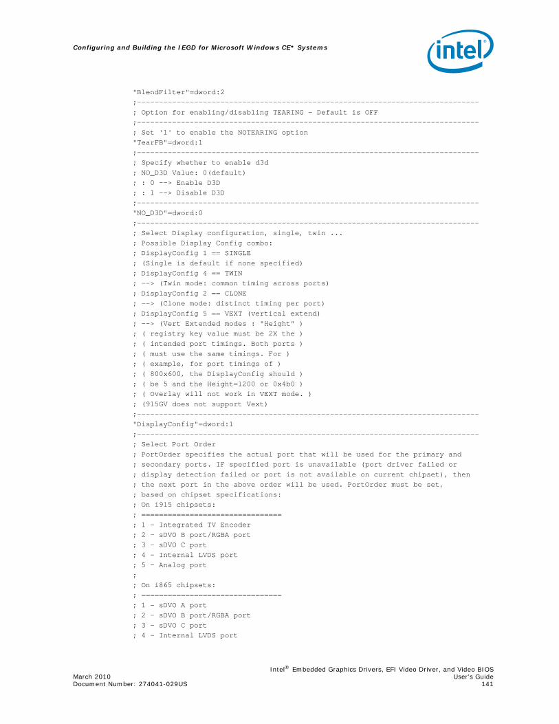
Intel® Embedded Graphics Drivers, EFI Video Driver, and Video BIOSMarch 2010 User’s GuideDocument Number: 274041-029US 141
Configuring and Building the IEGD for Microsoft Windows CE* Systems
"BlendFilter"=dword:2;------------------------------------------------------------------------------; Option for enabling/disabling TEARING - Default is OFF;------------------------------------------------------------------------------; Set '1' to enable the NOTEARING option"TearFB"=dword:1;------------------------------------------------------------------------------; Specify whether to enable d3d; NO_D3D Value: 0(default); : 0 --> Enable D3D; : 1 --> Disable D3D;------------------------------------------------------------------------------"NO_D3D"=dword:0;------------------------------------------------------------------------------; Select Display configuration, single, twin ...; Possible Display Config combo:; DisplayConfig 1 == SINGLE; (Single is default if none specified); DisplayConfig 4 == TWIN; --> (Twin mode: common timing across ports); DisplayConfig 2 == CLONE; --> (Clone mode: distinct timing per port); DisplayConfig 5 == VEXT (vertical extend); --> (Vert Extended modes : "Height" ); ( registry key value must be 2X the ); ( intended port timings. Both ports ); ( must use the same timings. For ); ( example, for port timings of ); ( 800x600, the DisplayConfig should ); ( be 5 and the Height=1200 or 0x4b0 ); ( Overlay will not work in VEXT mode. ); (915GV does not support Vext);------------------------------------------------------------------------------"DisplayConfig"=dword:1;------------------------------------------------------------------------------; Select Port Order; PortOrder specifies the actual port that will be used for the primary and; secondary ports. IF specified port is unavailable (port driver failed or; display detection failed or port is not available on current chipset), then; the next port in the above order will be used. PortOrder must be set,; based on chipset specifications:; On i915 chipsets:; ================================; 1 - Integrated TV Encoder; 2 - sDVO B port/RGBA port; 3 - sDVO C port; 4 - Internal LVDS port; 5 - Analog port;; On i865 chipsets:; ================================; 1 - sDVO A port; 2 - sDVO B port/RGBA port; 3 - sDVO C port; 4 - Internal LVDS port

Configuring and Building the IEGD for Microsoft Windows CE* Systems
Intel® Embedded Graphics Drivers, EFI Video Driver, and Video BIOSUser’s Guide March 2010 142 Document Number: 274041-029US
; 5 - Analog port;; On 835: If RGBA is used (sDVO B & C together), then use sDVO B number; to specify any parameter for it.;; On i81x chipsets:; =================; Port numbers:; 3 - sDVO port; 5 - Analog port;------------------------------------------------------------------------------"PortOrder"="52340";------------------------------------------------------------------------------; Set Clone Port resolutions;------------------------------------------------------------------------------; "CloneWidth"=dword:320; "CloneHeight"=dword:258; "CloneRefresh"=dword:3c
;------------------------------------------------------------------------------; Set "1" to enable Display Detection; DisplayDetect is to detect display child device before using it; (panel/tv/etc...).BEWARE, setting this to '1' will mean display for the; requested port will not be enabled if detection failed. Use this option wisely.;------------------------------------------------------------------------------"DisplayDetect"=dword:0;------------------------------------------------------------------------------; Set "1" to enable Dual Overlay in Vertical Extended in Windows CE 6.0; This is set by the user to enable Dual Hardware Overlays. This is a special; flag for a specific usage. When two apps request overlays, these two will; use the two hardware overlays;------------------------------------------------------------------------------ "OverlayDualVext"=dword:0;------------------------------------------------------------------------------; Overlay Color Correction Settings; Gamma: 32-bit integer in 24i.8f format, ranging from 0.6 - 6.0 decimal; Brightness: 32-bit integer ranging from 0 to 0xFFFF. 0x8000 = no correction; Contrast: 32-bit integer ranging from 0 to 0xFFFF. 0x8000 = no correction; Saturation: 32-bit integer ranging from 0 to 0xFFFF. 0x8000 = no correction;------------------------------------------------------------------------------; "OverlayGammaCorrectR"=dword:100; "OverlayGammaCorrectG"=dword:100; "OverlayGammaCorrectB"=dword:100; "OverlayBrightnessCorrect"=dword:8000; "OverlayContrastCorrect"=dword:8000; "OverlaySaturationCorrect"=dword:8000;******************************************************************************; The sections below are for the more detailed per port; registry configurations. It follows the same usage model and; key value meanings as the Windows INF registry configuration; file. Refer to the User’s Guide for details.;******************************************************************************;-------------------------------------------------------------------------; Config 1 - sDVO-B Port (For Almador) |;-------------------------------------------------------------------------

Intel® Embedded Graphics Drivers, EFI Video Driver, and Video BIOSMarch 2010 User’s GuideDocument Number: 274041-029US 143
Configuring and Building the IEGD for Microsoft Windows CE* Systems
; Following are the registry; entries for port's general config;-------------------------------------------------------------------------;;[HKEY_LOCAL_MACHINE\Drivers\Display\Intel\915GV\1\Port\2\General];; Advanced Edid Configuration; ---------------------------; "Edid"=dword:1; "EdidAvail"=dword:7 ; STD TIMINGS + EDID TIMINGS + USER TIMINGS; "EdidNotAvail"=dword:7 ; STD TIMINGS + USER TIMINGS;; EdidAvail and EdidNotAvail: <only 16 bits used>; ---------- -------------; These 2 parameters can be used to control the available timings for; any display. 'EdidAvail' is used when EDID is read from the display; device. If an attempt to read EDID is failed or 'Edid = 0' then; driver uses 'EdidNotAvail' flags.;; See below bit definitions for both 'EdidAvail' and 'EdidNotAvail';; BIT 0:; ------; 0 - Do not use driver built-in standard timings; 1 - Use driver built-in standard timings;; BIT1: <not applicable to EdidNotAvail>; ------; 0 - Do not use EDID block; 1 - Use EDID block and filter modes;; BIT2:; ------; 0 - Do not use user-DTDs; 1 - Use user-DTDs.;; BIT3-BIT15; -----------; Future use.;; Default behavior:; -----------------; If user does not provide EdidAvail and EdidNotAvail, then; EdidAvail = Use Std timings + Use EDID block and Filter modes; EdidNotAvail = Use Std timings;; Rotation Configuration; ----------------------; "Rotation"=dword:0; Rotation entries must be at a right; angle. An invalid entry will be ignored and; and no rotation will happen for primary.; In clone or twin modes, the secondary; port defaults to follow the primary (if set); 0 degrees = 0 (not rotated = default)
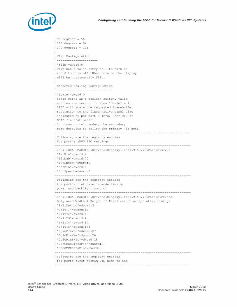
Configuring and Building the IEGD for Microsoft Windows CE* Systems
Intel® Embedded Graphics Drivers, EFI Video Driver, and Video BIOSUser’s Guide March 2010 144 Document Number: 274041-029US
; 90 degrees = 5A; 180 degrees = B4; 270 degrees = 10E;; Flip Configuration; ----------------------; "Flip"=dword:0; Flip has a valid entry of 1 to turn on; and 0 to turn off. When turn on the display; will be horizontally flip.;; Rendered Scaling Configuration; ------------------------------; "Scale"=dword:0; Scale works as a boolean switch. Valid; entries are zero or 1. When "Scale" = 1,; IEGD will scale the requested framebuffer; resolution to the fixed native panel size; indicated by per-port FPInfo, User-DTD or; EDID (in that order).; In clone or twin modes, the secondary; port defaults to follow the primary (if set);-------------------------------------------------------------------------; Following are the registry entries; for port's sDVO I2C settings;-------------------------------------------------------------------------;[HKEY_LOCAL_MACHINE\Drivers\Display\Intel\915GV\1\Port\2\sDVO]; "I2cPin"=dword:2; "I2cDab"=dword:70; "I2cSpeed"=dword:0; "DdcPin"=dword:0; "DdcSpeed"=dword:0;-------------------------------------------------------------------------; Following are the registry entries; for port's flat panel's mode-limits,; power and backlight control;-------------------------------------------------------------------------;[HKEY_LOCAL_MACHINE\Drivers\Display\Intel\915GV\1\Port\2\FPInfo]; Only need Width & Height if Panel cannot accept other timings; "BkltMethod"=dword:3; "BkltT1"=dword:1E; "BkltT2"=dword:4; "BkltT3"=dword:4; "BkltT4"=dword:14; "BkltT5"=dword:1F4; "GpioPinVdd"=dword:27; "GpioPinVee"=dword:26; "GpioPinBklt"=dword:28; "UseGMCHClockPin"=dword:0; "UseGMCHDataPin"=dword:0;-------------------------------------------------------------------------; Following are the registry entries; for ports first custom DTD mode to add;-------------------------------------------------------------------------
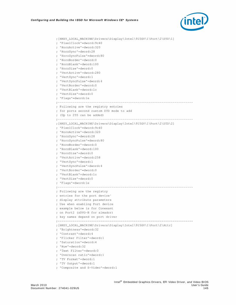
Intel® Embedded Graphics Drivers, EFI Video Driver, and Video BIOSMarch 2010 User’s GuideDocument Number: 274041-029US 145
Configuring and Building the IEGD for Microsoft Windows CE* Systems
;[HKEY_LOCAL_MACHINE\Drivers\Display\Intel\915GV\1\Port\2\DTD\1]; "PixelClock"=dword:9c40; "HorzActive"=dword:320; "HorzSync"=dword:28; "HorzSyncPulse"=dword:80; "HorzBorder"=dword:0; "HorzBlank"=dword:100; "HorzSize"=dword:0; "VertActive"=dword:280; "VertSync"=dword:1; "VertSyncPulse"=dword:4; "VertBorder"=dword:0; "VertBlank"=dword:1c; "VertSize"=dword:0; "Flags"=dword:1e;-------------------------------------------------------------------------; Following are the registry entries; for ports second custom DTD mode to add; (Up to 255 can be added);-------------------------------------------------------------------------;[HKEY_LOCAL_MACHINE\Drivers\Display\Intel\915GV\1\Port\2\DTD\2]; "PixelClock"=dword:9c40; "HorzActive"=dword:320; "HorzSync"=dword:28; "HorzSyncPulse"=dword:80; "HorzBorder"=dword:0; "HorzBlank"=dword:100; "HorzSize"=dword:0; "VertActive"=dword:258; "VertSync"=dword:1; "VertSyncPulse"=dword:4; "VertBorder"=dword:0; "VertBlank"=dword:1c; "VertSize"=dword:0; "Flags"=dword:1e;-------------------------------------------------------------------------; Following are the registry; entries for the port device'; display attribute parameters; Use when enabling Port device; example below is for Conexant; on Port2 (sDVO-B for almador); key names depend on port driver;-------------------------------------------------------------------------;[HKEY_LOCAL_MACHINE\Drivers\Display\Intel\915GV\1\Port\2\Attr]; "Brightness"=dword:32; "Contrast"=dword:4; "Flicker Filter"=dword:1; "Saturation"=dword:4; "Hue"=dword:32; "Text Filter"=dword:0; "Overscan ratio"=dword:1; "TV Format"=dword:1; "TV Output"=dword:1; "Composite and S-Video"=dword:1
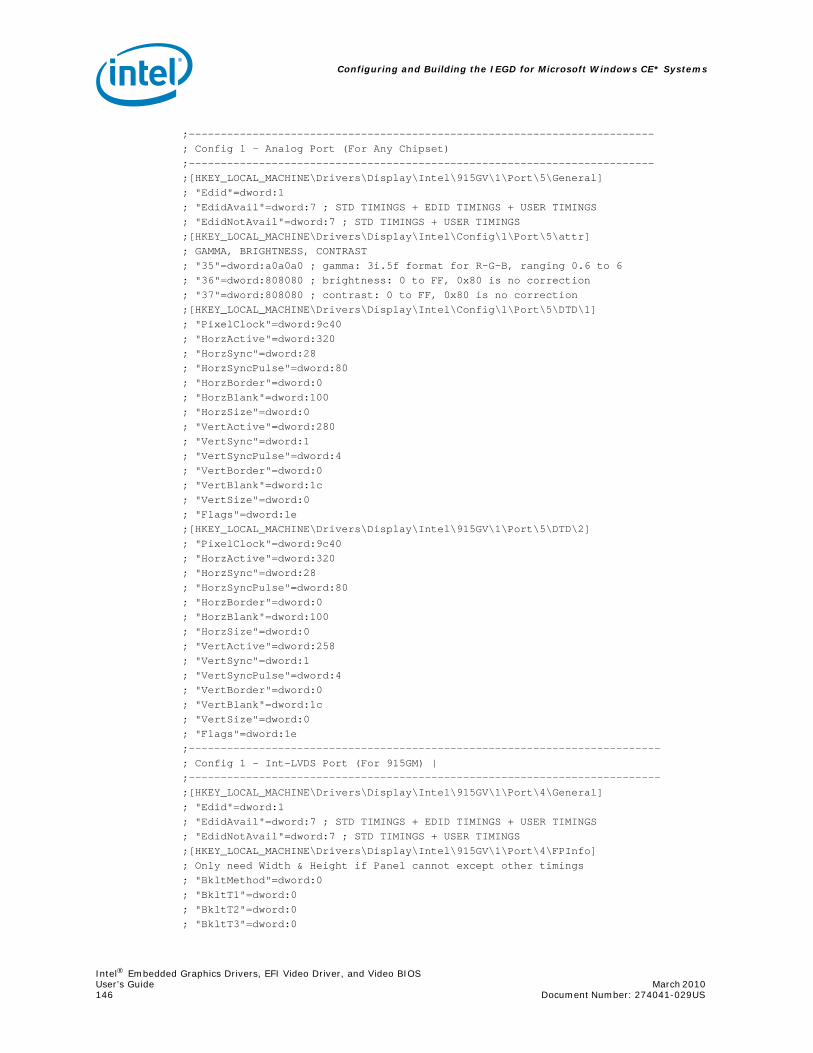
Configuring and Building the IEGD for Microsoft Windows CE* Systems
Intel® Embedded Graphics Drivers, EFI Video Driver, and Video BIOSUser’s Guide March 2010 146 Document Number: 274041-029US
;-------------------------------------------------------------------------; Config 1 - Analog Port (For Any Chipset);-------------------------------------------------------------------------;[HKEY_LOCAL_MACHINE\Drivers\Display\Intel\915GV\1\Port\5\General]; "Edid"=dword:1; "EdidAvail"=dword:7 ; STD TIMINGS + EDID TIMINGS + USER TIMINGS; "EdidNotAvail"=dword:7 ; STD TIMINGS + USER TIMINGS;[HKEY_LOCAL_MACHINE\Drivers\Display\Intel\Config\1\Port\5\attr]; GAMMA, BRIGHTNESS, CONTRAST; "35"=dword:a0a0a0 ; gamma: 3i.5f format for R-G-B, ranging 0.6 to 6; "36"=dword:808080 ; brightness: 0 to FF, 0x80 is no correction; "37"=dword:808080 ; contrast: 0 to FF, 0x80 is no correction;[HKEY_LOCAL_MACHINE\Drivers\Display\Intel\Config\1\Port\5\DTD\1]; "PixelClock"=dword:9c40; "HorzActive"=dword:320; "HorzSync"=dword:28; "HorzSyncPulse"=dword:80; "HorzBorder"=dword:0; "HorzBlank"=dword:100; "HorzSize"=dword:0; "VertActive"=dword:280; "VertSync"=dword:1; "VertSyncPulse"=dword:4; "VertBorder"=dword:0; "VertBlank"=dword:1c; "VertSize"=dword:0; "Flags"=dword:1e;[HKEY_LOCAL_MACHINE\Drivers\Display\Intel\915GV\1\Port\5\DTD\2]; "PixelClock"=dword:9c40; "HorzActive"=dword:320; "HorzSync"=dword:28; "HorzSyncPulse"=dword:80; "HorzBorder"=dword:0; "HorzBlank"=dword:100; "HorzSize"=dword:0; "VertActive"=dword:258; "VertSync"=dword:1; "VertSyncPulse"=dword:4; "VertBorder"=dword:0; "VertBlank"=dword:1c; "VertSize"=dword:0; "Flags"=dword:1e;--------------------------------------------------------------------------; Config 1 - Int-LVDS Port (For 915GM) |;--------------------------------------------------------------------------;[HKEY_LOCAL_MACHINE\Drivers\Display\Intel\915GV\1\Port\4\General]; "Edid"=dword:1; "EdidAvail"=dword:7 ; STD TIMINGS + EDID TIMINGS + USER TIMINGS; "EdidNotAvail"=dword:7 ; STD TIMINGS + USER TIMINGS;[HKEY_LOCAL_MACHINE\Drivers\Display\Intel\915GV\1\Port\4\FPInfo]; Only need Width & Height if Panel cannot except other timings; "BkltMethod"=dword:0; "BkltT1"=dword:0; "BkltT2"=dword:0; "BkltT3"=dword:0

Intel® Embedded Graphics Drivers, EFI Video Driver, and Video BIOSMarch 2010 User’s GuideDocument Number: 274041-029US 147
Configuring and Building the IEGD for Microsoft Windows CE* Systems
; "BkltT4"=dword:0; "BkltT5"=dword:0; "GpioPinVdd"=dword:0; "GpioPinVee"=dword:0; "GpioPinBklt"=dword:0; "UseGMCHClockPin"=dword:0; "UseGMCHDataPin"=dword:0;[HKEY_LOCAL_MACHINE\Drivers\Display\Intel\915GV\1\Port\4\Attr]; "27"=dword:1; Attribute "27" = Dual Channel (boolean); "18"=dword:1; Attribute "18" = Panel Fit Upscale (boolean);[HKEY_LOCAL_MACHINE\Drivers\Display\Intel\915GV\1\Port\4\DTD\1]; "PixelClock"=dword:9c40; "HorzActive"=dword:320; "HorzSync"=dword:28; "HorzSyncPulse"=dword:80; "HorzBorder"=dword:0; "HorzBlank"=dword:100; "HorzSize"=dword:0; "VertActive"=dword:280; "VertSync"=dword:1; "VertSyncPulse"=dword:4; "VertBorder"=dword:0; "VertBlank"=dword:1c; "VertSize"=dword:0; "Flags"=dword:1e;[HKEY_LOCAL_MACHINE\Drivers\Display\Intel\915GV\1\Port\4\DTD\2]; "PixelClock"=dword:9c40; "HorzActive"=dword:320; "HorzSync"=dword:28; "HorzSyncPulse"=dword:80; "HorzBorder"=dword:0; "HorzBlank"=dword:100; "HorzSize"=dword:0; "VertActive"=dword:258; "VertSync"=dword:1; "VertSyncPulse"=dword:4; "VertBorder"=dword:0; "VertBlank"=dword:1c; "VertSize"=dword:0; "Flags"=dword:1e;--------------------------------------------------------------------------; Config 1 - sDVO Port-B (For Napa);--------------------------------------------------------------------------;[HKEY_LOCAL_MACHINE\Drivers\Display\Intel\915GV\1]; "name"="IEGD sDVO Configuration File";[HKEY_LOCAL_MACHINE\Drivers\Display\Intel\915GV\1\Port\2]; "name"="svga";[HKEY_LOCAL_MACHINE\Drivers\Display\Intel\915GV\1\Port\2\FPInfo]; For a sDVO driver, sample settings for the panel:1400x1050; Only need Width & Height if Panel cannot except other timings; "Width"=dword:578; "Height"=dword:41A;[HKEY_LOCAL_MACHINE\Drivers\Display\Intel\915GV\1\Port\2\Attr]

Configuring and Building the IEGD for Microsoft Windows CE* Systems
Intel® Embedded Graphics Drivers, EFI Video Driver, and Video BIOSUser’s Guide March 2010 148 Document Number: 274041-029US
; "27"=dword:1; Attribute "27" = Dual Channel (boolean); Optional - Only enable for font anti-aliasing; Enabling this causes minor performance impact; Only recommended for TV Output.;[HKEY_LOCAL_MACHINE\System\GDI\Fontsmoothing];;[HKEY_LOCAL_MACHINE\System\GDI]; "ForceGRAY16"=dword:1;******************* INTEL DISPLAY DRIVER REGISTRY ENTRY END ******************

Intel® Embedded Graphics Drivers, EFI Video Driver, and Video BIOSMarch 2010 User’s GuideDocument Number: 274041-029US 149
Installing and Configuring Linux* OS Drivers
7.0 Installing and Configuring Linux* OS Drivers
This chapter describes the configuration and installation of the IEGD for Linux* systems. The IEGD supports X-Servers from the X.org* organization.
The Intel Linux driver is for use with the integrated graphics of Intel chipsets on the Embedded Intel Architecture roadmap. The driver supports 8-, 16- and 24-bit pixel depths, dual independent head configuration on capable hardware, flat panel, hardware 2D acceleration, hardware cursor, the XV extension, and the Xinerama extension. Stock library files, for example libva, can be used with IEGD.
7.1 Overview
Kernel patches, separate DRM modules, and kernel recompilation were all necessary in previous versions of the Intel Embedded Graphics Driver. In version 10.3.1, the IEGD Kernel Module (IKM) contains a combination of the agpgart and DRM modules which must be present for the Intel Embedded Graphic Driver. Both modules have been modified for the IEGD architecture and are combined with the Linux kernel.
The IEGD Linux distribution package contains drivers built for the following X-Servers:
• X-Server 1.3
• X-Server 1.4
• X-Server 1.5.3
• X-Server 1.6.x
The IEGD has been tested with the official version of these servers from the http://www.X.org Web site and may not operate with other versions of these servers.
During the installation, the X -version command returns a result indicating the server version, not the X.org version as was done in earlier versions.
7.2 Prerequisites
The following lists the prerequisites for installing and configuring the IEGD Linux* driver.
• Platform with supported Intel chipset.
• Platform with a minimum of 128 Mbytes.
• Resolution and timing specifications for the display devices that will be configured.
• Driver package consisting of directories and files (see the following reduced samples, which are located under the IEGD Linux directory).
Installing and Configuring Linux* OS Drivers
Intel® Embedded Graphics Drivers, EFI Video Driver, and Video BIOSUser’s Guide March 2010 150 Document Number: 274041-029US
Note: In the following, “Xorg-xserver 1.3/ is an example X-Server version that should be replaced with the version to be used.
— Documents/Relnotes Documents/UsersGuide.pdfDocuments/Xorg-xserver 1.3/iegd.4Documents/Xorg-xserver 1.3/IntelEscape.3x
— License/License.txt— Driver/<xserver name>/iegd_drv.o (or iegd_drv.so for Xorg
7.0)Driver/<xserver name>/libXlibXiegd_escape.aDriver/<xserver name>/libXiegd_escape.so.2.0.0Driver/<xserver name>/iegd_escape.hDriver/<xserver name>/lvds.soDriver/<xserver name>/tv.so
• Linux kernel header package for active running kernel.
— Direct Rendering support enabled.
• Other system capabilities
— IEGD Kernel Module for GART and DRM patches
• System administration privileges.
7.2.1 Supported Hardware
IEGD supports the following chipsets with integrated graphics:
• Intel® Atom™ Processor 400 and 500 Series
• Intel® Q45/G41/G45 Express chipset
• Intel® GM45/GL40/GS45 Express chipset
• Intel® System Controller Hub US15W/US15WP/WPT chipset
• Intel® Q35 Express chipset
• Mobile Intel® GLE960/GME965 Express chipset
• Intel® Q965 Express chipset
• Mobile Intel® 945GSE Express chipset
• Mobile Intel® 945GME Express chipset
• Intel® 945G Express chipset
• Intel® 915GV Express chipset
• Mobile Intel® 915GME Express chipset
• Mobile Intel® 910GMLE Express chipset

Intel® Embedded Graphics Drivers, EFI Video Driver, and Video BIOSMarch 2010 User’s GuideDocument Number: 274041-029US 151
Installing and Configuring Linux* OS Drivers
7.3 Installation
Refer to Section 1.7, “Downloading the IEGD and Video BIOS” on page 20 for instructions on obtaining the software. You can then install the IEGD by performing the instructions for your specific distribution in the following sections:
• “Linux Installer Overview”
• “Installing Fedora 7 (not supported with Intel® US15W)” on page 152
• “Installing Fedora 10” on page 154
• “Installing Wind River Linux Platform for Infotainment” on page 156
• “Installing Red Hat Embedded (for Intel® US15W/US15WP/WPT only)” on page 158
• “Installing Ubuntu IEGD Driver and Codec (for Intel® US15W/US15WP/WPT only)” on page 161
• “Installing Moblin 2.1 IVI (for Intel® US15W only)” on page 170
Note: If you are using a Linux distribution different from those for which these instructions are designed, you may need to adapt the steps for your specific situation.
7.3.1 Linux Installer Overview
The Linux installer does the following:
• Automatically copies all appropriate IEGD files for detected kernel version and X-Server
• Invokes the Intel Kernel Module (IKM) to patch the kernel
• Runs AGP and DRM tests to make sure IKM was installed correctly
• Invokes Modprobe to enable IEGD module
• Creates a shortcut to the IEGD GUI on the desktop
• Supports uninstallation of IEGD
The Linux Installer script is located in IEGD_10_3_1_Linux/Utilities/install.sh.
To execute the installer, run the following command:
./install.sh
To uninstall the IEGD files, run the following command:
./install.sh -u
Note: IEGD Linux Installer does not support all distributions. You may have to do a manual installation if your distribution is not supported. If an unsupported distribution is detected by the Linux installer, you have the option of continuing the installation manually.

Installing and Configuring Linux* OS Drivers
Intel® Embedded Graphics Drivers, EFI Video Driver, and Video BIOSUser’s Guide March 2010 152 Document Number: 274041-029US
7.3.2 Installing Fedora 7 (not supported with Intel® US15W)
IEGD v10.3.1 provides a Linux installer for Fedora 7 with X-Server 1.3 support. Other X-Server versions such as 1.4, 1.5, and 1.6 may work, but if the installer detects an unsupported distribution you can choose to continue with a standard installation. It also allows you to uninstall, reinstall, or upgrade your Fedora 7 driver.
Note: Before installing Fedora, determine whether you need to do either or all of the following:
• Disable SELinux security to allow the IEGD driver to load. To disable it, use the Security application in X. If you do not disable SELinux security, you will need to configure SELinux to allow IEGD to operate.
• Disable AIGLX because IEGD does not support or work with it. To disable AIGLX, add the Option “AIGLX” “FALSE” command to the xorg.conf file in the ServerFlags section.
Installation Steps
1. Log into a system administration account.
2. Untar the driver package to a convenient location.
tar -xvzf <driver package.tgz>
This creates a directory structure in the directory where you extracted the .tgz file and contains the following directories:
— IEGD_10_3_1_Linux - Contains the Documents, Driver, License, IKM, and Utilities subdirectories. The Driver directory contains subdirectories for the supported versions of the X.org X-Servers. This directory contains man pages for IEGD.The Documents directory contains the release notes.The License directory contains the license for the IEGD release.The Utilities directory contains IEGD utilities, including the iegdgui runtime configuration utility.The IKM directory contains files for patching the Linux kernel AGPGART module.
3. Invoke the Linux installer using the command “./install.sh” from the IEGD_10_3_1_Linux/Utilities folder. If successful, skip to step 11.
Note: If the installer does not work, use the following manual install steps.
4. Check the version of the X-Server your system is running. Type the following command:
X -version
Note: For Fedora 7 (F7), the result from this command is 1.3.
5. Copy the IEGD driver binary, iegd_drv.o (or iegd_drv.so), from the IEGD_10_3_1_Linux/driver/<xserver name> directory to the X-Server's modules/drivers directory. For F7 (X-Server 1.3-based distribution), the default location is /usr/lib/xorg/modules/drivers. This location can vary by distribution so check your system for the proper path.cd IEGD_10_3_1_Linux/driver/Xorg-xserver-1.3cp iegd_drv.so /usr/lib/xorg/modules/drivers

Intel® Embedded Graphics Drivers, EFI Video Driver, and Video BIOSMarch 2010 User’s GuideDocument Number: 274041-029US 153
Installing and Configuring Linux* OS Drivers
6. Copy the necessary port driver files (*.so files in the IEGD_10_3_1_Linux/driver/<xserver name> directory) to the X-Server lib/modules directory. The default installation location is /usr/lib/xorg/modules. This location can vary, so check your system for the proper path. After the required port drivers have been copied, you can specify them in the PortDrivers option in the Device section of the config file. For more information on specifying the PortDrivers option, refer to Table 44, “Supported Driver Options” on page 187. For example, to copy all the port drivers use the following command:
cp *.so /usr/lib/xorg/modules
7. Copy the escape control library libXiegd_escape.so.2.0.0 from the IEGD_10_3_1_Linux/driver/<xserver name> directory to the X-Server library directory. The default installation location is /usr/lib. For example,
cp libXiegd_escape.so.2.0.0 /usr/lib
8. In the X-Server library directory, create symbolic links for the escape library aliases:
cd /usr/lib ln -sfv libXiegd_escape.so.2.0.0 libXiegd_escape.soln -sfv libXiegd_escape.so.2.0.0 libXiegd_escape.so.2ldconfig
9. From the X-Server directory you are using, unzip the iegd.4.gz file and copy the driver man page, iegd.4, to the man/man4 directory. The default installation location is /usr/share/man/man4. This location can vary by distribution so check your system for the proper path. For example, for Fedora 7, cd IEGD_10_3_1_Linux/driver/Xorg-xserver-1.3
cp iegd.4.gz /usr/share/man/man4
cp iegd_escape.3x.gz /usr/share/man/man3x
10. Execute the following commands:
cd IEGD_10_3_1_Linux/IKM
./install.sh
(Note: if a permissions error is displayed, do a chmod +x install.sh)
modprobe iegd_mod
11. Modify your xorg.conf file to include a device section for this driver and a Monitor section for your display. See Section 7.6.1, “Configuration Overview” on page 179 for details on the driver configuration and the list of supported options. The default installation location for this file is /etc/X11.
12. Reboot

Installing and Configuring Linux* OS Drivers
Intel® Embedded Graphics Drivers, EFI Video Driver, and Video BIOSUser’s Guide March 2010 154 Document Number: 274041-029US
7.3.3 Installing Fedora 10
To install the IEGD v10.3.1 on Fedora 10, follow the following steps:
• “Installation Steps”
• “OpenGL Installation”
Note: Before installing Fedora, determine whether you need to do either or all of the following:
• Disable SELinux security to allow the IEGD driver to load. To disable it, use the Security application in X. If you do not disable SELinux security, you will need to configure SELinux to allow IEGD to operate.
• Disable AIGLX because IEGD does not support or work with it. To disable AIGLX, add the Option “AIGLX” “FALSE” command to the xorg.conf file in the ServerFlags section.
Notes: There are known bugs in the X.org X-Server 1.5.3 version used by Fedora 10. The bugs affect OpenGL applications.
Without applying the work-around below, many OpenGL applications will not display properly and display only a blank (black) window.
A simple workaround, described below, is needed for distributions using a 1.5.x version of the X-Server, however it does not apply to 1.6.0 version of the X-Server.
Workaround for AIGLX and X-Server version 1.5.x
Note: This workaround applies to the two previous bullets above.
In the xorg.conf file, set the “GlxVisuals” option to “all.” This goes in the ServerFlags section of the file, as shown in the following example:
Section "ServerFlags"
Option "Xinerama" "False"Option "AllowMouseOpenFail" "1"Option "BlankTime" "0"…. Option "AIGLX" "False"Option "GlxVisuals" "all"
EndSection
Installation Steps
1. Log into a system administration account.
2. Untar the driver package to a convenient location.tar -xvzf <driver package.tgz>This creates a directory structure in the directory where you extracted the .tgz file and contains the following directories:
— IEGD_10_3_1_Linux - Contains the Documents, Driver, License, IKM, and Utilities subdirectories. The Driver directory contains subdirectories for the supported versions of the X.org X-Servers. This directory contains man pages for IEGD.The Documents directory contains the release notes.The License directory contains the license for the IEGD release.

Intel® Embedded Graphics Drivers, EFI Video Driver, and Video BIOSMarch 2010 User’s GuideDocument Number: 274041-029US 155
Installing and Configuring Linux* OS Drivers
The Utilities directory contains IEGD utilities, including the iegdgui runtime configuration utility.The IKM directory contains files for patching the Linux kernel AGPGART module.
3. Check the version of the X-Server your system is running. Type the following command:
X -version
Note: For Fedora 10, the result from this command is 1.5.3.
4. Copy the IEGD driver binary, iegd_drv.o (or iegd_drv.so), from the IEGD_10_3_1_Linux/driver/<xserver name> directory to the X-Server's modules/drivers directory. For F10 (X-Server 1.5.3 based distribution), the default location is /usr/lib/xorg/modules. This location can vary by distribution so check your system for the proper path.cd IEGD_10_3_1_Linux/driver/Xorg-xserver-1.5.3cp iegd_drv.so /usr/lib/xorg/modules/drivers
5. Copy the necessary port driver files (*.so files in the IEGD_10_3_1_Linux/driver/<xserver name> directory) to the X-Server lib/modules directory. The default installation location is /usr/lib/xorg/modules. This location can vary, so check your system for the proper path. After the required port drivers have been copied, you can specify them in the PortDrivers option in the Device section of the config file. For more information on specifying the PortDrivers option, refer to Table 44, “Supported Driver Options” on page 187. For example, to copy all the port drivers use the following command:
cp *.so /usr/lib/xorg/modules
6. Copy the escape control library libXiegd_escape.so.2.0.0 from the IEGD_10_3_1_Linux/driver/<xserver name> directory to the X-Server library directory. The default installation location is /usr/lib. For example,
cp libXiegd_escape.so.2.0.0 /usr/lib
7. In the X-Server library directory, create symbolic links for the escape library aliases:
cd /usr/lib ln -sfv libXiegd_escape.so.2.0.0 libXiegd_escape.soln -sfv libXiegd_escape.so.2.0.0 libXiegd_escape.so.2ldconfig
8. Install IKM and add the Xorg file:cd IEGD_10_3_1_Linux/IKM./install.sh
(Note: if a permissions error is displayed, do a chmod +x install.sh)Answer y to questiondepmod -amodprobe iegd_mod
9. From the X-Server directory you are using, unzip the iegd.4.gz file and copy the driver man page, iegd.4, to the man/man4 directory. The default installation location is /usr/share/man/man4. This location can vary by distribution so check your system for the proper path. For example, for Fedora 10, cd IEGD_10_3_1_Linux/driver/Xorg-xserver-1.5.3
cp iegd.4.gz /usr/share/man/man4
cp iegd_escape.3x.gz /usr/share/man/man3x
10. Reboot.

Installing and Configuring Linux* OS Drivers
Intel® Embedded Graphics Drivers, EFI Video Driver, and Video BIOSUser’s Guide March 2010 156 Document Number: 274041-029US
OpenGL Installation
If you want to install OpenGL, use the following instructions.
1. Set up the required share libraries for OGL/ES:cd IEGD_10_3_1_Linux/driver/Xorg-xserver-1.5.3cp -v iegd_dri.so /usr/lib/dri
Use one of the commands below depending on your chipset:cp -v libGL_ga.so.1.2 libGL.so.1.2 (for US15W chipset)cp -v libGLgn3.so libGL.so.1.2 (for 910/915/94 chipsets)cp -v libGLgn4.so libGL.so.1.2 (for 965/GM45 chipsets)
cp -v libGL.so.1.2 /usr/lib/libGL.so.1.2cd /etc/X11
2. Edit the xorg.conf file and add this parameter in the ServerFlags section:Option "GlxVisuals" "All"
3. In the X-Server library directory, create symbolic links for the escape library aliases:cd /usr/libln -sfv /usr/lib/libGL.so.1.2 libGL.soln -sfv /usr/lib/libGL.so.1.2 libGL.so.1cd /libln -sfv libexpat.so.1.5.2 libexpat.so.0ldconfigcd IEGD_10_3_1_Linux/IKM./install.shAnswer y to questiondepmod -Aemodprobe iegd_mod
4. Reboot
5. After reboot:
a. export LIBGL_DEBUG=VERBOSE
b. glxinfoThe result of this command provides information about the OpenGL environment.
c. glxgearsThe result of this command displays spinning gears
7.3.4 Installing Wind River Linux Platform for Infotainment
To set up Wind River Linux Platform for Infotainment for use with the IEGD drivers, complete the following tasks:
• Install the IEGD Driver (see below)
• Install Helix (see page 158)
• Install the codecs (see page 158)

Intel® Embedded Graphics Drivers, EFI Video Driver, and Video BIOSMarch 2010 User’s GuideDocument Number: 274041-029US 157
Installing and Configuring Linux* OS Drivers
7.3.4.1 Installing the IEGD Driver
1. Untar the driver package to a convenient location.
tar -xvzf <driver package.tgz>
This creates a directory structure in the directory where you extracted the .tgz file and contains the following directories:
— IEGD_10_3_1_Linux - Contains the Documents, Driver, License, IKM, and Utilities subdirectories.
The Documents subdirectory contains the Xorg.xserver-x.x subdirectory. This directory also contains man pages for the IEGD.
The Driver directory contains subdirectories for the supported versions of the Xorg X servers.
The Utilities directory contains IEGD utilities, including the iegdgui runtime configuration utility.
2. Copy the driver files to the correct location:cp iegd_drv.so /usr/lib/xorg/modules/driverscp iegd_drv_video.so /usr/lib/xorg/modules/driverscp iegd_drv.so /usr/X11R6/lib/modules/dricp iegd_drv_video.so /usr/X11R6/lib/modules/dricp lvds.so /usr/lib/xorg/modulescp sdvo.so /usr/lib/xorg/modulescp libXiegd_escape.so.2.0.0 /usr/lib
3. Link the IEGD escape library:ln -s /usr/lib/libXiegd_escape.so.2.0.0 /usr/lib/libXiegd_escape.so.2ln -s /usr/lib/libXiegd_escape.so.2.0.0 /usr/lib/libXiegd_escape.so
4. Copy the 3D driver to the correct locations:cp iegd_dri.so /usr/lib/dricp iegd_dri.so /usr/X11R6/lib/dricp libGL_ga.so.1.2 /usr/lib
5. Link the libGL library:ln -s /usr/lib/libGL_ga.so.1.2 /usr/lib/libGL.so.1.2ln -s /usr/lib/libGL_ga.so.1.2 /usr/lib/libGL.so.1ln -s /usr/lib/libGL_ga.so.1.2 /usr/lib/libGL.so
6. Copy the video driver binary to the correct location:cp libva.so.0.29.0 /usr/lib
7. Link the video library files:ln -s /usr/lib/libva.so.0.29.0 /usr/lib/libva.so.0ln -s /usr/lib/libva.so.0.29.0 /usr/lib/libva.soldconfig
8. Install the IKM:cd /root/release/IEGD_10_3_1_Linux/IKMARCH=i386 ./install.sh
9. Start X-Server after the IKM installation:modprobe drminsmod iegd_mod.kostartx

Installing and Configuring Linux* OS Drivers
Intel® Embedded Graphics Drivers, EFI Video Driver, and Video BIOSUser’s Guide March 2010 158 Document Number: 274041-029US
7.3.4.2 Installing Helix
1. mkdir /usr/lib/helix
2. cd /usr/lib/helix
3. tar -xvzf <your path>/splay-plugin-atlas-01.2.0.tgz
7.3.4.3 Installing Codecs
To install the codecs first you must have sharutils.
1. Get sharutils:apt-get install sharutils tar -xvzf menlow_codec_1[1].8.8.22.tar.gz./menlow_codec_1.8.8.22.shartar cvfz menlow_codec.tgz *.so
2. Install the codecs:cd /usr/lib/helix/splaymkdir bkupcd bkupmv /usr/lib/helix/splay/mpgfformat.so .mv /usr/lib/helix/splay/mp4vrender.socd ..cp /<from_your_tar_menlow_codec>/libipp_hx*.so .
7.3.5 Installing Red Hat Embedded (for Intel® US15W/US15WP/WPT only)
Embedded versions of Linux* often use a “build system” to create the IEGD Kernel object (kernel module) used by the Red Hat Embedded (RHE) targeted system. The build system should consist of the standard Fedora 7 OS at the very minimum.
7.3.5.1 Creating the IEGD Kernel Module
To create the IEGD Kernel object (kernel module) on a Fedora 7 build system, perform the following steps.
1. Download and install the kernel-devel-2.6.23.15-80.fc7.cb.4.i686.rpm package on the build system.
a. Get kernel-devel-2.6.23.15-80.fc7.cb.4.i686.rpm from Red Hat (or from RHE CD) and download to the build system.
b. rpm -i --force kernel-devel-2.6.23.15-80.fc7.cb.4.i686.rpm
2. Download and extract (but do not install) the IEGD v10.3.1 tarball (iegd_10_3_1_Linux.tgz) on the build system.
a. Create IEGD v10.3.1 tarball from the CED tool and download it to the build system.
b. Extract IEGD v10.3.1 tarball for creating the kernel object (kernel module):mkdir /tmp/iegd_10_3_1cp iegd_10_3_1.tgz /tmp/iegd_10_3_1cd /tmp/iegd_10_3_1tar -xvzf IEGD_10_3_1_Linux.tgz

Intel® Embedded Graphics Drivers, EFI Video Driver, and Video BIOSMarch 2010 User’s GuideDocument Number: 274041-029US 159
Installing and Configuring Linux* OS Drivers
3. Create IEGD v10.3.1 kernel object (kernel module) on the build system:
a. (Optional)The build will fail unless the following patch is applied to the sources. The linux/config.h file does not exist on kernels after 2.6.19.
diff -rup a/IEGD_10_3_1_Linux/IKM/drm/iegd_drv.c b/IEGD_10_3_1_Linux/IKM/drm/iegd_drv.c--- a/IEGD_10_3_1_Linux/IKM/drm/iegd_drv.c 2008-05-19 00:09:07.000000000 -0400+++ b/IEGD_10_3_1_Linux/IKM/drm/iegd_drv.c 2008-06-19 23:50:47.000000000 -0400@@ -50,7 +50,6 @@ * */
#include <linux/config.h>#include "iegd.h"#include <drmP.h>#include <drm.h>
b. Change to the IKM directory: cd /tmp/iegd_10_3_1_Linux/IKM/
c. Set the KERNELDIR environment variable used by the IEGD kernel object build script: export KERNELDIR=/usr/src/kernels/2.6.23.15-80.fc7.cb.4-i686
d. Run IEGD kernel object build script (IKM Patch Instructions)./install.sh(Note: if a permissions error is displayed, do a chmod +x install.sh)
The result is a kernel object (kernel module) file, iegd_mod.ko, used on the RHE target system.
e. Copy iegd_mod.ko to the network or USB for installing onto RHE target system.
7.3.5.2 Installing IEGD on a Red Hat Embedded System
To install IEGD v10.3.1 on a RHE “target system” perform the following steps:
1. Install the latest US15W RHE on the target system. Example:
a. Get cb-7-i386-CD.iso from Red Hat ftp://ftp.redhat.com/pub/redhat/gnupro/AtomZ5xx-US15W/).
b. Create a CDROM from cb-7-i386-CD.iso.
c. Boot up CDROM of cb-7-i386-CD.iso image on the target system (may require BIOS configuration to boot from CD) and installed default, Kickstart menu option. The system reboots (may require BIOS configuration to boot from the hard drive).
Note: The Kickstart ks.cfg file is expecting to have a PATA drive with a name of CDROM. If that is not present, you must determine the name of your drive and use that name instead.
d. If prompted for a password, log in with the password redhat.

Installing and Configuring Linux* OS Drivers
Intel® Embedded Graphics Drivers, EFI Video Driver, and Video BIOSUser’s Guide March 2010 160 Document Number: 274041-029US
e. Install kernel-devel-2.6.23.15-80.fc7.cb.4.i686.rpm package:
1) Get kernel-devel-2.6.23.15-80.fc7.cb.4.i686.rpm from Red Hat and download it to the target system.
2) rpm -i --force kernel-devel-2.6.23.15-80.fc7.cb.4.i686.rpm
2. Install IEGD v10.3.1 on the target system.
a. Use CED to create an IEGD Linux* installation including an example IEGD configuration that is added to your existing xorg.conf file.
b. Download and extract IEGD v10.3.1 tarball:tar -xvzf <driver package>.tgzwhere <driver package> is replaced with the actual name, for example, IEGD_10_3_1_Linux.
c. Apply the recommended section of the sample IEGD conf file to your target xorg.conf file. See Section 7.6.1, “Configuration Overview” on page 179 for details on the driver configuration and the list of supported options.
d. Change directory to Xorg-xserver-1.3.cd IEGD_10_3_1_Linux/driver/Xorg-xserver-1.3
e. Copy the necessary port driver files (*.so files in the IEGD_10_3_1_Linux/driver/Xorg-xserver-1.3 directory) to the X-Server lib/modules directory. The default installation location is /usr/lib/xorg/modules. cp *.so /usr/lib/xorg/modulescp iegd_drv.so /usr/lib/xorg/modules/drivers
f. Copy the escape control library libXiegd_escape.so.2.0.0 from the IEGD_10_3_1_Linux/driver/<xserver name> directory to the X-Server library directory. The default installation location is /usr/lib. For example,cp libXiegd_escape.so.2.0.0 /usr/lib
g. In the X-Server library directory, create symbolic links for the escape library aliases:cd /usr/lib ln -sfv libXiegd_escape.so.2.0.0 libXiegd_escape.soln -sfv libXiegd_escape.so.2.0.0 libXiegd_escape.so.2ldconfig
h. Copy the IEGD DRI module: cd IEGD_10_3_1_Linux/driver/Xorg-xserver-1.3mkdir /usr/lib/drichmod 775 /usr/lib/dricp iegd_dri.so /usr/lib/dri
i. Copy and enable the IEGD Video Library:cp iegd_drv_video.so /usr/lib/xorg/modules/driverscp libva.so.0.29.0 /usr/libcd /usr/libln -s libva.so.0.29.0 libva.soln -s libva.so.0.29.0 libva.so.0export LIBVA_DRIVERS_PATH=/usr/lib/xorg/modules/drivers/ldconfig

Intel® Embedded Graphics Drivers, EFI Video Driver, and Video BIOSMarch 2010 User’s GuideDocument Number: 274041-029US 161
Installing and Configuring Linux* OS Drivers
j. From the IEGD_10_3_1_Linux/Documents directory, copy the driver man page, iegd.4, to the man/man4 directory. The default installation location is /usr/share/man/man4. This location can vary by distribution so check your system for the proper path. For example:cd IEGD_10_3_1_Linux/driver/Xorg-xserver-1.3cp iegd.4.gz /usr/share/man/man4
k. Copy the previously built IEGD v10.3.1 kernel object (kernel module), iegd_mod.ko, into kernel library modules:
1) cd IEGD_10_3_1_Linux/IKM
2) ./install.sh rhe
3) Answer “y” followed by <Enter> when prompted.
4) cp iegd_mod.ko /lib/modules/2.6.23.15-80.fc7.cb.4.i686/kernel/drivers/char/drm/
5) depmod –a
6) modprobe drm
7) modprobe iegd_mod
Note: If the modprobe does not work, insert the module using the command insmod iegd_mod.ko
l. Restart the system and start up X.
Note: For video playback, you may need to install Helix (see page 169) and the Intel US15W codecs, which are available as a separate download under evaluation license only.
7.3.5.3 Installing Codecs
• UMG Codecs: 1.8.8.22 (contact your Intel representative for the file)
• WMV Codecs: Helix Windows Media Integration Project (https://helix-client.helixcommunity.org/2005/devdocs/windowsMedia.html - Download source code and compile binary for asfff.so, avc1.so, dmp4.so, wma9.so, wmarender.so, wmerender.so)
• To install Intel Media Codec use the following commands: tar –zxvf menlow_codec_1[1].8.8.22.tar.gzcp *.so /usr/lib/helix/splayrm /usr/lib/helix/splay/mpgfformat.sorm /usr/lib/helix/splay/h264dec.sorm /usr/lib/helix/splay/mp4vrender.sorm /usr/lib/helix/splay/wmvrender.sorm /usr/lib/helix/splay/wmv9.so
7.3.6 Installing Ubuntu IEGD Driver and Codec (for Intel® US15W/US15WP/WPT only)
To set up Ubuntu for use with the IEGD drivers, complete the following tasks:
• Install the Ubuntu operating system (see below)
• Install the IEGD driver (see page 167)
• Install the Helix DBus Server (see page 169)

Installing and Configuring Linux* OS Drivers
Intel® Embedded Graphics Drivers, EFI Video Driver, and Video BIOSUser’s Guide March 2010 162 Document Number: 274041-029US
7.3.6.1 Installing the Ubuntu OS
1. Download Ubuntu package from http://cdimage.ubuntu.com/moblin/releases/hardy/mid-8.04.1-menlow.mic.tar.bz2.
2. Set up a system (Intel® Atom™ or other IA platform) that runs with Ubuntu OS (Desktop). Make sure your system is able to connect to the Internet.
3. Connect two hard drives to your system, a primary drive for the Ubuntu desktop (login as root or use sudo wherever possible) and a secondary, empty hard drive which will be used for a clean Ubuntu MID OS setup.
4. Boot up your system and copy the Ubuntu package to your system root directory.
5. Format the root and swap partitions for second hard drive:Device Boot Start End Blocks Id System/dev/sdb1 * 1 30269 243135711 83 Linux/dev/sdb2 30270 30401 1060290 82 Linux swap / Solaris
6. Create primary partition and swap for your second hard disk:mke2fs -jv /dev/sdb1mkswap /dev/sdb2mkdir /vmount /dev/sdb1 /v
7. Extract the project directory:(cd /v; tar -jxpv --strip 1 -f - project/) < mid-8.04.1-menlow.mic.tar.bz2.tar
8. Chroot to the new file system on your second hard drive:chroot /v /bin/bashHOME=/rootmount -t proc none /procmount -t sysfs none /sysmount -t devpts none /dev/pts
9. Set up the network where the <Name-server-IP-address> and <your proxy settings here> will vary for different networks:cat > /etc/resolv.conf <<RESOLV_CONFsearch <domain.com>nameserver <Name-server-IP-address>RESOLV_CONFexport http_proxy=<your proxy settings here>
10. Add source repository:cat > /etc/apt/sources.list <<SOURCES_LISTdeb http://ports.ubuntu.com/ubuntu-ports hardy main restricted universe multiversedeb-src http://ports.ubuntu.com/ubuntu-ports hardy main restricted universe multiversedeb http://ports.ubuntu.com/ubuntu-ports hardy-updates main restricted universe multiversedeb-src http://ports.ubuntu.com/ubuntu-ports hardy-updates main restricted universe multiversedeb http://ppa.launchpad.net/ubuntu-mobile/ubuntu hardy maindeb-src http://ppa.launchpad.net/ubuntu-mobile/ubuntu hardy mainSOURCES_LIST

Intel® Embedded Graphics Drivers, EFI Video Driver, and Video BIOSMarch 2010 User’s GuideDocument Number: 274041-029US 163
Installing and Configuring Linux* OS Drivers
11. Update and download with kernel source package. Ignore the NO_PUBKEY error encountered after you are finished with the update.apt-get updateapt-get install --reinstall language-pack-encd /usr/srcapt-get build-dep linux-image-2.6.24-19-lpiaapt-get source --compile linux-image-2.6.24-19-lpia
12. To allow the make operation to complete faster, execute the following command at command line:export CONCURRENCY_LEVEL=<processors + 1>
where <processors + 1> is the number of processors available on your system plus 1. For example, the command for the Intel® Atom™ Processor Z530 would beexport CONCURRENCY_LEVEL=3.
Note: The CONCURRENCY_LEVEL value should be one greater than the number of processors available on your system.
13. To create the kernel.config file, execute the following command at the command line:make oldconfig
14. Build the kernel:mkdir /usr/src/framecd /usr/src/frame(cd /usr/src/linux-2.6.24/debian/build; tar cf - custom-source-lpia) | tar xpf -mv custom-source-lpia linux-2.6.24.3cd linux-2.6.24.3
15. Make sure to edit following sections in your kernel.config. ## Protocols#CONFIG_PNPACPI=yCONFIG_BLK_DEV=y# CONFIG_BLK_DEV_FD is not set# CONFIG_BLK_CPQ_DA is not set# CONFIG_BLK_CPQ_CISS_DA is not set# CONFIG_BLK_DEV_DAC960 is not set# CONFIG_BLK_DEV_UMEM is not set# CONFIG_BLK_DEV_COW_COMMON is not set# CONFIG_BLK_DEV_LOOP is not set# CONFIG_BLK_DEV_NBD is not set# CONFIG_BLK_DEV_SX8 is not set# CONFIG_BLK_DEV_UB is not set# CONFIG_BLK_DEV_RAM is not set# CONFIG_CDROM_PKTCDVD is not set# CONFIG_ATA_OVER_ETH is not set# CONFIG_MISC_DEVICES is not set# CONFIG_IDE is not set
. . .

Installing and Configuring Linux* OS Drivers
Intel® Embedded Graphics Drivers, EFI Video Driver, and Video BIOSUser’s Guide March 2010 164 Document Number: 274041-029US
## SCSI device support## CONFIG_RAID_ATTRS is not setCONFIG_SCSI=yCONFIG_SCSI_DMA=y# CONFIG_SCSI_TGT is not set# CONFIG_SCSI_NETLINK is not setCONFIG_SCSI_PROC_FS=y
. . .
## SCSI support type (disk, tape, CD-ROM)#CONFIG_BLK_DEV_SD=y
# CONFIG_CHR_DEV_ST is not set# CONFIG_CHR_DEV_OSST is not set# CONFIG_BLK_DEV_SR is not setCONFIG_CHR_DEV_SG=y# CONFIG_CHR_DEV_SCH is not set
. . .
## Some SCSI devices (e.g. CD jukebox) support multiple LUNs#CONFIG_SCSI_MULTI_LUN=yCONFIG_SCSI_CONSTANTS=yCONFIG_SCSI_LOGGING=y# CONFIG_SCSI_SCAN_ASYNC is not setCONFIG_SCSI_WAIT_SCAN=m
. . .
## SCSI Transports## CONFIG_SCSI_SPI_ATTRS is not set# CONFIG_SCSI_FC_ATTRS is not set# CONFIG_SCSI_ISCSI_ATTRS is not set# CONFIG_SCSI_SAS_LIBSAS is not set# CONFIG_SCSI_SRP_ATTRS is not set# CONFIG_SCSI_LOWLEVEL is not setCONFIG_ATA=y# CONFIG_ATA_NONSTANDARD is not setCONFIG_ATA_ACPI=y# CONFIG_SATA_AHCI is not set

Intel® Embedded Graphics Drivers, EFI Video Driver, and Video BIOSMarch 2010 User’s GuideDocument Number: 274041-029US 165
Installing and Configuring Linux* OS Drivers
# CONFIG_SATA_SVW is not setCONFIG_ATA_PIIX=y# CONFIG_SATA_MV is not set# CONFIG_SATA_NV is not set# CONFIG_PDC_ADMA is not set# CONFIG_SATA_QSTOR is not set# CONFIG_SATA_PROMISE is not set# CONFIG_SATA_SX4 is not set# CONFIG_SATA_SIL is not set# CONFIG_SATA_SIL24 is not set# CONFIG_SATA_SIS is not set# CONFIG_SATA_ULI is not set# CONFIG_SATA_VIA is not set# CONFIG_SATA_VITESSE is not set# CONFIG_SATA_INIC162X is not setCONFIG_PATA_ACPI=y# CONFIG_PATA_ALI is not set# CONFIG_PATA_AMD is not set# CONFIG_PATA_ARTOP is not set# CONFIG_PATA_ATIIXP is not set# CONFIG_PATA_CMD640_PCI is not set# CONFIG_PATA_CMD64X is not set# CONFIG_PATA_CS5520 is not set# CONFIG_PATA_CS5530 is not set# CONFIG_PATA_CS5535 is not set# CONFIG_PATA_CS5536 is not set# CONFIG_PATA_CYPRESS is not set# CONFIG_PATA_EFAR is not setCONFIG_ATA_GENERIC=y# CONFIG_PATA_HPT366 is not set# CONFIG_PATA_HPT37X is not set# CONFIG_PATA_HPT3X2N is not set# CONFIG_PATA_HPT3X3 is not set# CONFIG_PATA_IT821X is not set# CONFIG_PATA_IT8213 is not set# CONFIG_PATA_JMICRON is not set# CONFIG_PATA_TRIFLEX is not set# CONFIG_PATA_MARVELL is not setCONFIG_PATA_MPIIX=y# CONFIG_PATA_OLDPIIX is not set# CONFIG_PATA_NETCELL is not set# CONFIG_PATA_NS87410 is not set# CONFIG_PATA_NS87415 is not set# CONFIG_PATA_OPTI is not set# CONFIG_PATA_OPTIDMA is not set# CONFIG_PATA_PDC_OLD is not set# CONFIG_PATA_RADISYS is not set# CONFIG_PATA_RZ1000 is not set# CONFIG_PATA_SC1200 is not set# CONFIG_PATA_SERVERWORKS is not set# CONFIG_PATA_PDC2027X is not set# CONFIG_PATA_SIL680 is not set# CONFIG_PATA_SIS is not set# CONFIG_PATA_VIA is not set# CONFIG_PATA_WINBOND is not set

Installing and Configuring Linux* OS Drivers
Intel® Embedded Graphics Drivers, EFI Video Driver, and Video BIOSUser’s Guide March 2010 166 Document Number: 274041-029US
# CONFIG_PATA_PLATFORM is not set# CONFIG_MD is not set# CONFIG_FUSION is not set
. . . ## Graphics support#CONFIG_AGP=m# CONFIG_AGP_ALI is not set# CONFIG_AGP_ATI is not set# CONFIG_AGP_AMD is not set# CONFIG_AGP_AMD64 is not set# CONFIG_AGP_INTEL is not set# CONFIG_AGP_NVIDIA is not set# CONFIG_AGP_SIS is not set# CONFIG_AGP_SWORKS is not set
# CONFIG_AGP_VIA is not set# CONFIG_AGP_EFFICEON is not setCONFIG_DRM=m# CONFIG_DRM_TDFX is not set# CONFIG_DRM_R128 is not set# CONFIG_DRM_RADEON is not set# CONFIG_DRM_MGA is not set# CONFIG_DRM_SIS is not set# CONFIG_DRM_VIA is not set# CONFIG_DRM_VIA_CHROME9 is not set# CONFIG_DRM_SAVAGE is not set# CONFIG_VGASTATE is not set# CONFIG_VIDEO_OUTPUT_CONTROL is not setCONFIG_FB=yCONFIG_FIRMWARE_EDID=y# CONFIG_FB_DDC is not setCONFIG_FB_CFB_FILLRECT=yCONFIG_FB_CFB_COPYAREA=yCONFIG_FB_CFB_IMAGEBLIT=y# CONFIG_FB_CFB_REV_PIXELS_IN_BYTE is not set# CONFIG_FB_SYS_FILLRECT is not set# CONFIG_FB_SYS_COPYAREA is not set# CONFIG_FB_SYS_IMAGEBLIT is not set# CONFIG_FB_SYS_FOPS is not setCONFIG_FB_DEFERRED_IO=y# CONFIG_FB_SVGALIB is not set# CONFIG_FB_MACMODES is not set# CONFIG_FB_BACKLIGHT is not setCONFIG_FB_MODE_HELPERS=yCONFIG_FB_TILEBLITTING=y
16. Build the kernel:make oldconfigmakemake install modules_install
17. Make sure /lib/modules/<kernel number>/kernel/drivers/char/ has /drm/drm.ko in it.

Intel® Embedded Graphics Drivers, EFI Video Driver, and Video BIOSMarch 2010 User’s GuideDocument Number: 274041-029US 167
Installing and Configuring Linux* OS Drivers
18. Install required packages:apt-get install xserver-xorgapt-get install xorgapt-get install mesa-utils
Note: If you want to install additional packages, go to http://packages.ubuntu.com/hardy/ to see the names of the packages and their utilities.
19. Exit the chroot environment and install grub:exitsudo mkdir /v/boot/grubcat > /v/boot/grub/menu.lst <<MENU_LSTdefault 0timeout 5#hiddenmenucolor cyan/blue white/bluetitle Ubuntu 8.04.1, kernel 2.6.24-19-lpia (multi user)root (hd0,0)kernel /boot/vmlinuz-2.6.24.6 root=/dev/sda1 ro ht=onMENU_LSTgrub-install --root-directory=/v /dev/sdb
20. Shut down the system. The second hard drive should now have the bootable OS. Connect this hard drive to a Eurotech/CrownBeach Board or other US15W system with PATA interface. Proceed to the driver installation section.
7.3.6.2 Installing the IEGD Driver for Ubuntu
Platform: Intel® Atom™
System Memory: 1Gbyte DDR2 533 MHz
Video Memory: 8 Mbytes Stolen Memory, 256 Mbytes Aperture Memory (Support from ECG BIOS version 0.17 and above)
Display Interface: CRT (1400x1050)
OS: Ubuntu 8.04.1 Hardy
X-Window: Xorg-server 1.4.1
Kernel: 2.6.24.3
Software Required:
• Driver: the latest IEGD driver
• Helix: splay-plugin-atlas-01.2.0 (Download from https://helix-client.helixcommunity.org/Releases)
• UMG Codecs: 1.8.8.22 (contact your Intel representative for the file)
• WMV Codecs: Helix Windows Media Integration Project (https://helix-client.helixcommunity.org/2005/devdocs/windowsMedia.html - Download source code and compile binary for asfff.so, avc1.so, dmp4.so, wma9.so, wmarender.so, wmerender.so)

Installing and Configuring Linux* OS Drivers
Intel® Embedded Graphics Drivers, EFI Video Driver, and Video BIOSUser’s Guide March 2010 168 Document Number: 274041-029US
Installation Steps
1. Make sure the software listed above is on your hard drive before proceeding to the next step.
2. Boot up the target Intel® Atom™ system.You will see the fastar login prompt. Just log in as root and no password is required.
3. Refer to “Editing the Linux* OS Configuration File Directly” on page 180 to edit /etc/X11/xorg.conf file to work with IEGD.
4. Start the X server:startx
5. Copy driver binary, where <driver> is the IEGD_10_3_1_Linux/driver directory:cd <driver>/Xorg-xserver-1.4 cp iegd_drv.so /usr/lib/xorg/modules/driverscd /usr/libln –sfv libexpat.so.1.5.2 libexpat.soln –sfv libexpat.so.1.5.2 libexpat.so.1cd <driver>/Xorg-xserver-1.4cp *.so /usr/lib/xorg/modules cp libXiegd_escape.so.2.0.0 /usr/lib cp libGL* /usr/lib
6. Enable DRI:mkdir /usr/lib/dricp iegd_dri.so /usr/lib/dri
7. Link the library:cd /usr/libln -s libXiegd_escape.so.2.0.0 libXiegd_escape.soln -s libXiegd_escape.so.2.0.0 libXiegd_escape.so.2ln -sfv libGL_ga.so.1.2 libGL.soln -sfv libGL_ga.so.1.2 libGL.so.1ln –sfv libexpat.so.1.5.2 libexpat.so.0
8. Perform patching:cd <driver>/IKM./install.sh
Note: If a permissions error is displayed, do a chmod +x install.sh or try using the command sudo bash ./install/sh
depmod –amodprobe iegd_modstartx
The driver and 3D should be up and running now.
9. Make sure the installation is pointing to Tungsten and not MESA:glxinfo | grep "vendor" Failure on this will cause 3D and VA to fail.

Intel® Embedded Graphics Drivers, EFI Video Driver, and Video BIOSMarch 2010 User’s GuideDocument Number: 274041-029US 169
Installing and Configuring Linux* OS Drivers
7.3.6.3 Installing the Helix DBus Server
1. Get helix-dbus-server-src-0.6.0.tgz from the Helix community release link at https://helix-client.helixcommunity.org/Releases. Untar and build according to the README file.
2. Install: cd player/dbus-server./dist --prefix=/usr prepare./dist installhelix-dbus-server
Note: If you do not install splay to /usr/lib/helix/splay, you should export HELIX_LIBS to the path of splay.
3. Install Helix Framework:cd <Folder contain Helix Package>tar –zxvf splay-plugin-atlas-01.2.0.tgzcd splaycp *.* /usr/lib/helix/splay
4. Install Intel Media Codec: tar –zxvf menlow_codec_1[1].8.8.22.tar.gzcp *.so /usr/lib/helix/splayrm /usr/lib/helix/splay/mpgfformat.sorm /usr/lib/helix/splay/h264dec.sorm /usr/lib/helix/splay/mp4vrender.sorm /usr/lib/helix/splay/wmvrender.sorm /usr/lib/helix/splay/wmv9.so
5. Enable Video Decode:cd <driver>/Xorg-xserver1.4 cp libva.so.0.29.0 /usr/libcp iegd_drv_video.so /usr/lib/xorg/modules/driverscd /usr/lib ln -s libva.so.0.29.0 libva.soln -s libva.so.0.29.0 libva.so.0export LIBVA_DRIVERS_PATH=/usr/lib/xorg/modules/drivers/
6. Get the WMV Codec File from Helix Windows Media Integration Project and copy over to splay folder. Without this step, all WMV cannot play.cp *.so /usr/lib/helix/splay
7. Play Video:cd /usr/lib/helix/splay./splay /<infile>/movie/VA/Clips/10KBC.mov
where <infile> is the local path to the media file to be played.

Installing and Configuring Linux* OS Drivers
Intel® Embedded Graphics Drivers, EFI Video Driver, and Video BIOSUser’s Guide March 2010 170 Document Number: 274041-029US
7.3.7 Installing Moblin 2.1 IVI (for Intel® US15W only)
There are two ways to get IEGD on Moblin:
• Install the pre-integrated Moblin image (see Section 7.3.7.1)
OR
• Manually install IEGD on Moblin by doing the following:
— “Preparing for the Intel Embedded Graphics Driver Installation”
— “Installing the Intel Embedded Graphics Driver (IEGD) for Moblin 2.1”
7.3.7.1 Install the Pre-integrated Moblin Image
1. Download the pre-integrated Moblin image from the moblin.org site athttp://moblin.org/projects/ivi
2. Follow the installation directions at moblin.org to create a live USB flash image and install on a hard disk.
7.3.7.2 Manually Installing IEGD
1. Download and install the standalone Moblin image with open source VESA driver. This image is available from Moblin.org at: http://moblin.org/projects/2.1-ivi-fc-release.
2. Follow the installation directions at moblin.org to create a live USB flash image and install on a hard disk.
7.3.7.3 Preparing for the Intel Embedded Graphics Driver Installation
Proceed with the following installation steps.
1. Log in as SuperUser.
2. Edit grub.conf and comment out the line with splash screen:vi /boot/grub/grub.conf
This step is recommended so that the system can be debugged instead of remaining stuck at the splash screen or blank screen.
3. Edit the inittab file using the following command and change the default value from 5 to 3:vi /etc/inittab

Intel® Embedded Graphics Drivers, EFI Video Driver, and Video BIOSMarch 2010 User’s GuideDocument Number: 274041-029US 171
Installing and Configuring Linux* OS Drivers
7.3.7.4 Installing the Intel Embedded Graphics Driver (IEGD) for Moblin 2.1
1. Untar the driver package to a convenient location using the following command:
tar -xvzf <driver package.tgz>
This creates a directory structure in the directory where you extracted the .tgz file. It contains the following directories:
— IEGD_10_3_1_Linux - Contains the Documents, Driver, License, IKM, and Utilities subdirectories.The Documents subdirectory contains the release notes for IEGD.The Driver directory contains subdirectories for the supported versions of the X.org X-Servers.The License directory contains the license for the IEGD release.The Utilities directory contains IEGD utilities, including the iegdgui runtime configuration utility.The IKM directory contains files for patching the Linux kernel AGPGART module.
2. Verify the version of the X-Server your system is running using the following command:X -version
Note: For Moblin 2.1, the result from this command should be 1.6.4.901.
3. Copy the IEGD driver binary, iegd_drv.o (or iegd_drv.so), from the IEGD_10_3_1_Linux/driver/<xserver name_version> directory to the X-Server's modules/drivers directory using the commands below. For Moblin 2.1 (X-Server 1.6-based distribution), the default location is /usr/lib/xorg/modules/drivers.
Note: The default location can vary by distribution so check your system for the proper path.
cd IEGD_10_3_1_Linux/driver/Xorg-xserver-1.6.4.901cp iegd_drv.so /usr/lib/xorg/modules/driverscp iegd_drv_video.so /usr/lib/xorg/modules/drivers
cp lvds.so /usr/lib/xorg/modulescp sdvo.so /usr/lib/xorg/modules
cp iegd_dri.so /usr/lib/dricp libGL_ga.so.1.2 /usr/lib cp libva.so.0.29.0 /usr/libcp libXiegd_escape.so.2.0.0 /usr/lib
cp libEGL.so.1.0 /usr/libcp libGLESv1_CM.so.1.1.0 /usr/libcp libGLESv2.so.2.0.0 /usr/libcp egl_xdri.so /usr/libcp egl_iegd_dri.so /usr/lib/dri

Installing and Configuring Linux* OS Drivers
Intel® Embedded Graphics Drivers, EFI Video Driver, and Video BIOSUser’s Guide March 2010 172 Document Number: 274041-029US
4. In the lib directory, create symbolic links for the following aliases:cd /usr/lib
ln -sfv libXiegd_escape.so.2.0.0 libXiegd_escape.soln -sfv libXiegd_escape.so.2.0.0 libXiegd_escape.so.2
ln -sfv libva.so.0.29.0 libva.so.0.29ln -sfv libva.so.0.29.0 libva.so.0ln -sfv libva.so.0.29.0 libva.so
ln -sfv libGL_ga.so.1.2 libGL.soln -sfv libGL_ga.so.1.2 libGL.so.1ln -sfv libGL_ga.so.1.2 libGL.so.1.2
ln -sfv libEGL.so.1.0 libEGL.soln -sfv libEGL.so.1.0 libEGL.so.1
ln -sfv libGLESv1_CM.so.1.1.0 libGLESv1_CM.so.1ln -sfv libGLESv1_CM.so.1.1.0 libGLESv1_CM.soln -sfv libGLESv2.so.2.0.0 libGLESv2.so.2.0ln -sfv libGLESv2.so.2.0.0 libGLESv2.so.2ln -sfv libGLESv2.so.2.0.0 libGLESv2.so
cd /lib
ln -sfv libexpat.so.1.5.2 libexpat.so.0ldconfig
Note: If an error is displayed, “command not found” then use /sbin/ldconfig in place of the ldconfig command above.
5. Execute the following commands:cd IEGD_10_3_1_Linux/IKM./install.sh
Note: If a permissions error is displayed, do a chmod +x install.sh or try using the command sudo bash ./install.sh
modprobe iegd_mod
Note: If an error is displayed, “command not found” then use /sbin/modprobe iegd_mod in place of the command above.
6. Modify your xorg.conf file to include a device section for this driver and a monitor section for your display.
The default installation location for this file is /etc/X11.
Note: You need to use the Configuration EDitor tool (CED) to create an IEGD compatible xorg.conf file that correctly uses IEGD as the driver and sets the IEGD configuration properly. See “Platform Configuration Using CED” on page 29 for details.
7. Reboot.

Intel® Embedded Graphics Drivers, EFI Video Driver, and Video BIOSMarch 2010 User’s GuideDocument Number: 274041-029US 173
Installing and Configuring Linux* OS Drivers
7.3.7.5 Known Issues
If you encounter text corruption, please set your default color depth to 24-bit in the screen section in the Xorg.conf. See “Screen Section” on page 185 for details.
7.4 IKM Patch Instructions
The IKM process is designed to replace the need to patch your kernel GART and DRM.
See also the following topics:
• “Finding and Installing the Kernel Source (Headers)”
• “Installing IKM with Fedora”
• “Using the IEGD Kernel Module”
• “Linux Installer IKM Validation”
• “Uninstalling the IKM”
7.4.1 Finding and Installing the Kernel Source (Headers)
• Building the IKM requires kernel headers and the kernel config file for the kernel the IKM will be created for.
• KERNEL_VERSION is the output of the command uname -r
• If you use a kernel from your distribution you will typically have a package with all the files required to build kernel modules for your kernel image.
— On Fedora and compatibles (e.g., Red Hat) this is the kernel-devel package. Or if you run kernel-smp or kernel-xen, you need kernel-smp-devel or kernel-xen-devel, respectively.
— In some distributions (e.g., in RHEL or Fedora) the installation of the kernel-devel / kernel-headers package will be a newer version than the one you currently run. In such a case, you may need to upgrade the kernel package itself and reboot.
7.4.2 Installing IKM with Fedora
This section can be used if you are trying to get a non-supported LINUX distribution running with IKM. Fedora 10 is not supported for these instructions.
1. Install kernel-$ARCH-devel. The version of the package must be the same as the running kernel. Replace $ARCH with architecture of the kernel (e.g., smp).
2. Install Kernel-devel from the CD/DVD or through the yum utility.
3. Install the kernel source for the version you are running by choosing one of the following methods.
— If you are using a CD or DVD, search for the rpm package for kernel-$ARCH-devel and install using
rpm -ivh kernel-$ARCH-devel
— For the yum utility, type the following command:
yum install kernel-develThis will install kernel-devel and resolve dependencies. Note that, as stated earlier, kernel-devel that is installed through this method might not be the same version as a running kernel. In this case IKM compilation might be successful, however, when trying to insert it to the running kernel, modprobe/insmod will produce an error. The solution is to upgrade the kernel-package itself and reboot to make the Linux* OS run the updated kernel.

Installing and Configuring Linux* OS Drivers
Intel® Embedded Graphics Drivers, EFI Video Driver, and Video BIOSUser’s Guide March 2010 174 Document Number: 274041-029US
4. Hardlink is a utility that consolidates duplicates files in one or more directories by traversing the directories and searching for duplicate files. When Hardlink finds duplicate files, it uses one of them as the master, removes all other duplicates, and places a hardlink for each one pointing to the master file. Download Hardlink from the Fedora site:http://fedora.secsup.org/linux/core/5/i386/os/Fedora/RPMS/hardlink-1.0-1.21.2.i386.rpm
5. Install Hardlink using one of the methods described below.
— Run the following command:
rpm -ivh hardlink-1.0-1.21.2.i386.rpm
— Run the following command through yum utility, making sure the computer is connected to the Internet:
yum install hardlink
Hardlink is now installed and will resolve any dependencies.
6. Compile the module using the following commands:
cd IEGD_10_3_1_Linux/IKM
./install.sh
depmod -a
modprobe iegd_mod
7. Modify your xorg.conf file to include a device section for this driver and a Monitor section for your display. See Section 7.6.1, “Configuration Overview” on page 179 for details on the driver configuration and the list of supported options. The default installation location for this file is /etc/X11.
8. Reboot.
At this point, when X Windows starts, it should be using the IEGD driver. To verify this, you can check your Xorg log, or run the iegdgui utility (found in the Utilities directory).
Note: You may need to set the iegdgui file properties to be executable before it will run.
7.4.3 Using the IEGD Kernel Module
Note: This needs to be run after adding the IEGD components and updating the symbolic links in the Linux* OS.
An installation script is provided to perform the installation. The script generates the Makefile together with the compilation environment for that particular kernel or distro. To install the IKM, run the shell script provided:
cd IEGD_10_3_1_Linux/IKM
./install.sh(Note: if a permissions error is displayed, do a chmod +x install.sh)
The installation script detects the kernel version and points to the proper header files location before creating the Makefile. The script then calls the Make program to start the compilation process. After compilation is complete, the script tries to install the IKM. If the script is run from a normal user, it prompts for the superuser password before copying the generated file and then runs a depmod -a command to resolve module dependencies.

Intel® Embedded Graphics Drivers, EFI Video Driver, and Video BIOSMarch 2010 User’s GuideDocument Number: 274041-029US 175
Installing and Configuring Linux* OS Drivers
To insert the module into the kernel, run
modprobe iegd_mod
This will load all the modules that iegd_mod depends on before loading iegd_mod itself.
IKM installation requires a matching kernel source tree and a working Linux build system. Some of the programs require some additional libraries.
7.4.4 Linux Installer IKM Validation
The Linux Installer also validates the IKM installation using AGP and DRM tests to verify that it is installed and working correctly, as described below.
7.4.4.1 AGP Test
The AGP test opens the AGPGART component and then communicates using IOCTLs to ensure that the AGP portion of the IKM works.
You may see “Error on AGPIOC_BIND. Trying new address for bind 8000.” This is OK. The validation test is looking for unused memory. If an actual error occurs, the script test will immediately exit.
7.4.4.2 DRM Test
The DRM tests work in a similar manner. It is a comprehensive set of tests to verify the functionality of all device file interfaces. The test opens the DRM and communicates using the IOCTLs to ensure that the DRM portion of the IKM works.
Compilation for AGP>cd …/IEGD_10_3_1_Linux/IKM/agp>gcc –o agp_test agp_test.c
Compilation for DRM>cd …/IEGD_10_3_1_Linux/IKM/drm>gcc –o drm_test drm_test.c
ExecutionOptional parameter –v [verbose mode].
AGP>./agp_test
DRM>./drm_test
7.4.4.3 Kernel Checker
The purpose of the kernel checker is to ensure that the Kernel API that IKM is dependent on exists.
When you run install.sh it calls the ikmchecker.sh which is found in the kernelchecker_tests folder. Next, you see the message “Checking kernel dependencies …” and after you have executed the script there should be a build.log file in the kernelchecker_tests folder displaying the results after compilation. If there is an error there will be an error.log file in that folder and the error will be displayed in the console. The APIs that the Linux installer checks for are shown in tables 35 through 43.
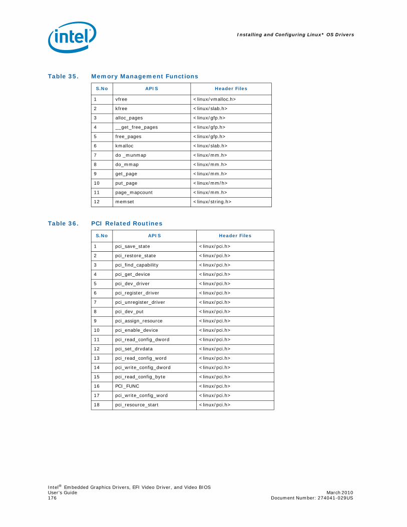
Installing and Configuring Linux* OS Drivers
Intel® Embedded Graphics Drivers, EFI Video Driver, and Video BIOSUser’s Guide March 2010 176 Document Number: 274041-029US
Table 35. Memory Management Functions
S.No APIS Header Files
1 vfree <linux/vmalloc.h>
2 kfree <linux/slab.h>
3 alloc_pages <linux/gfp.h>
4 __get_free_pages <linux/gfp.h>
5 free_pages <linux/gfp.h>
6 kmalloc <linux/slab.h>
7 do _munmap <linux/mm.h>
8 do_mmap <linux/mm.h>
9 get_page <linux/mm.h>
10 put_page <linux/mm/h>
11 page_mapcount <linux/mm.h>
12 memset <linux/string.h>
Table 36. PCI Related Routines
S.No APIS Header Files
1 pci_save_state <linux/pci.h>
2 pci_restore_state <linux/pci.h>
3 pci_find_capability <linux/pci.h>
4 pci_get_device <linux/pci.h>
5 pci_dev_driver <linux/pci.h>
6 pci_register_driver <linux/pci.h>
7 pci_unregister_driver <linux/pci.h>
8 pci_dev_put <linux/pci.h>
9 pci_assign_resource <linux/pci.h>
10 pci_enable_device <linux/pci.h>
11 pci_read_config_dword <linux/pci.h>
12 pci_set_drvdata <linux/pci.h>
13 pci_read_config_word <linux/pci.h>
14 pci_write_config_dword <linux/pci.h>
15 pci_read_config_byte <linux/pci.h>
16 PCI_FUNC <linux/pci.h>
17 pci_write_config_word <linux/pci.h>
18 pci_resource_start <linux/pci.h>
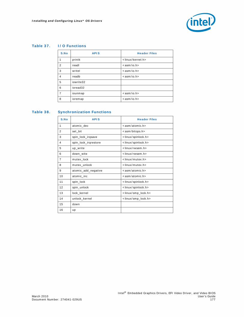
Intel® Embedded Graphics Drivers, EFI Video Driver, and Video BIOSMarch 2010 User’s GuideDocument Number: 274041-029US 177
Installing and Configuring Linux* OS Drivers
Table 37. I/O Functions
S.No APIS Header Files
1 printk <linux/kernel.h>
2 readl <asm/io.h>
3 writel <asm/io.h>
4 readb <asm/io.h>
5 iowrite32
6 ioread32
7 iounmap <asm/io.h>
8 ioremap <asm/io.h>
Table 38. Synchronization Functions
S.No APIS Header Files
1 atomic_dec <asm/atomic.h>
2 set_bit <asm/bitops.h>
3 spin_lock_irqsave <linux/spinlock.h>
4 spin_lock_irqrestore <linux/spinlock.h>
5 up_write <linux/rwsem.h>
6 down_wite <linux/rwsem.h>
7 mutex_lock <linux/mutex.h>
8 mutex_unlock <linux/mutex.h>
9 atomic_add_negative <asm/atomic.h>
10 atomic_inc <asm/atomic.h>
11 spin_lock <linux/spinlock.h>
12 spin_unlock <linux/spinlock.h>
13 lock_kernel <linux/smp_lock.h>
14 unlock_kernel <linux/smp_lock.h>
15 down
16 up

Installing and Configuring Linux* OS Drivers
Intel® Embedded Graphics Drivers, EFI Video Driver, and Video BIOSUser’s Guide March 2010 178 Document Number: 274041-029US
Table 39. Page Related Functions
S.No APIS Header Files
1 virt_to_page <asm/page.h>
2 pmd_offset <asm/pgtable-3level.h>
3 pud_none <asm/pgtable-3level.h>
4 pte_none <asm/pgtable-3level.h>
5 pte_clear <asm/pgtable-3level.h>
6 pte_unmap <asm/pgtable.h>
7 pte_offset_map <asm/pgtable.h>
8 pgd_offset <asm/pgtable.h>
9 SetPageLocked <linux/page-flags.h>
10 unlock_page <linux/pagemap.h>
11 SetPageReserved <linux/page-flags.h>
12 ClearPageReserved <linux/page-flags.h>
13 io_remap_pfn_range <asm/pgtable.h>
14 copy_page <asm/page.h>
15 pte_page <asm/pgtable-3level.h>
16 pmd_none <asm/pgtable.h>
17 change_page_attr <asm/cacheflush.h>
Table 40. Linked Lists
S.No APIS Header Files
1 list_add <linux/list.h>
2 list_del <linux/list.h>
3 list_for _each <linux/list.h>
Table 41. Linux Driver Model Specific
S.No APIS Header Files
1 module_init <linux/init.h>
2 module_exit <linux/init.h>
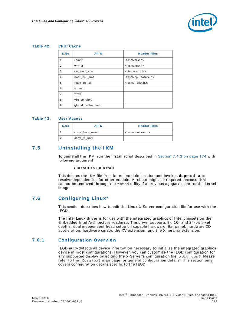
Intel® Embedded Graphics Drivers, EFI Video Driver, and Video BIOSMarch 2010 User’s GuideDocument Number: 274041-029US 179
Installing and Configuring Linux* OS Drivers
7.5 Uninstalling the IKM
To uninstall the IKM, run the install script described in Section 7.4.3 on page 174 with following argument:
./install.sh uninstall
This deletes the IKM file from kernel module location and invokes depmod -a to resolve dependencies for other module. A reboot might be required because IKM cannot be removed through the rmmod utility if a previous agpgart is part of the kernel image.
7.6 Configuring Linux*
This section describes how to edit the Linux X-Server configuration file for use with the IEGD.
The Intel Linux driver is for use with the integrated graphics of Intel chipsets on the Embedded Intel Architecture roadmap. The driver supports 8-, 16- and 24-bit pixel depths, dual independent head setup on capable hardware, flat panel, hardware 2D acceleration, hardware cursor, the XV extension, and the Xinerama extension.
7.6.1 Configuration Overview
IEGD auto-detects all device information necessary to initialize the integrated graphics device in most configurations. However, you can customize the IEGD configuration for any supported display by editing the X-Server’s configuration file, xorg.conf. Please refer to the Xorg(5x) man page for general configuration details. This section only covers configuration details specific to the IEGD.
Table 42. CPU/Cache
S.No APIS Header Files
1 rdmsr <asm/msr.h>
2 wrmsr <asm/msr.h>
3 on_each_cpu <linux/smp.h>
4 boot_cpu_has <asm/cpufeature.h>
5 flush_tlb_all <asm/tlbflush.h
6 wbinvd
7 wmb
8 virt_to_phys
9 global_cache_flush
Table 43. User Access
S.No APIS Header Files
1 copy_from_user <asm/uaccess.h>
2 copy_to_user

Installing and Configuring Linux* OS Drivers
Intel® Embedded Graphics Drivers, EFI Video Driver, and Video BIOSUser’s Guide March 2010 180 Document Number: 274041-029US
To configure the IEGD for the Linux* OS, you must edit the X server’s configuration file. You can either edit the configuration directly or you can use CED to create configurations that must then be copied into the configuration file. Even if you use CED to create a configuration, you must still edit the Linux configuration file.
7.6.2 Linux* OS Configuration Using CED
You can configure the Linux* driver settings using CED as described in Section 3.0, “Platform Configuration Using CED” on page 29 or in the CED online help.
The output file (yourbuildnamehere.x) from CED contains the settings required to configure the IEGD for Linux systems and can be pasted into the appropriate sections of the xorg_conf file.
7.6.3 Editing the Linux* OS Configuration File Directly
Instead of using the CED, you can edit the xorg.conf file directly. The following procedure outlines the steps to follow when editing the Linux* configuration file. Section 7.6.4, “The Linux* OS Configuration File” on page 180 provides details on each section of the configuration file.
1. Log in as root and open the configuration file for editing. The configuration file is typically located in the /etc/X11 directory but may be located elsewhere on your system.
2. In the Device section of the configuration file, enter the appropriate information for your driver. The configuration file must have at least one Device section. The Device section lets you define information about IEGD. You can use a single Device section for single, twin, or clone configurations. For Dual Independent Head configurations, you must specify a second Device section.
3. In the Screen section, enter information for each display in your configuration. The configuration file must have at least one Screen section. The Screen section binds a Device with a Monitor and lets you define resolution modes for the display. The Screen section is referenced in the ServerLayout section of the configuration file.
4. In the Monitor section, define monitor specifications and timings that will be used for the display. You must have a Monitor section defined for each display in your configuration. The Monitor section is referenced by the Screen section.
5. Save your changes to the file. For systems booted to run level 3, startx to restart. For systems booted to run level 5, kill X (Alt-backspace) to restart. Reboot if necessary.
7.6.4 The Linux* OS Configuration File
To configure the IEGD for use with the Linux* OS, you must edit the Linux configuration file (xorg.conf). There are several sections within the configuration that must be edited or created, including:
• Device Sections
• Screen Sections
• Monitor Sections
• ServerLayout Section (when configuring DIH)
• ServerFlags Section (when configuring Xinerama)
The above Sections are described following the sample file. Please see the xorg.conf man pages for complete details.

Intel® Embedded Graphics Drivers, EFI Video Driver, and Video BIOSMarch 2010 User’s GuideDocument Number: 274041-029US 181
Installing and Configuring Linux* OS Drivers
Figure 34. Example xorg.conf File#### X Config options generated from CED## x11 conf skeleton## DriverVer=##
Section "Screen"
Identifier "Screen0"Device "Intel_IEGD-0"Monitor "Monitor0"DefaultDepth 24SubSection "Display"Depth 24Modes "1024x600"EndSubSection
EndSection
Section "Monitor"
Identifier "Monitor0"HorizSync 30.0 - 75.0VertRefresh 50.0 - 75.0Option "dpms"
EndSection
Section "Monitor"
Identifier "Monitor1"HorizSync 30.0 - 75.0VertRefresh 50.0 - 75.0Option "dpms"
EndSection
# Primary (First/only) displaySection "Device"
Identifier "Intel_IEGD-0"Driver "iegd"VendorName "Intel(R) DEG"BoardName "Embedded Graphics"BusID "0:2:0"Screen 0Option "PcfVersion" "1792"Option "ConfigId" "1"Option "ALL/1/name" "dih965"Option "ALL/1/General/PortOrder" "42000"Option "ALL/1/General/DisplayConfig" "8"Option "ALL/1/General/DisplayDetect" "0"Option "ALL/1/General/CloneRefresh" "60"Option "ALL/1/General/CloneWidth" "1280"Option "ALL/1/General/CloneHeight" "1024"Option "ALL/1/Port/4/General/name" "LVDS"Option "ALL/1/Port/4/General/EdidAvail" "0"Option "ALL/1/Port/4/General/EdidNotAvail" "5"Option "ALL/1/Port/4/General/Rotation" "0"Option "ALL/1/Port/4/General/Edid" "0"

Installing and Configuring Linux* OS Drivers
Intel® Embedded Graphics Drivers, EFI Video Driver, and Video BIOSUser’s Guide March 2010 182 Document Number: 274041-029US
Option "ALL/1/Port/4/FpInfo/BkltMethod" "0"Option "ALL/1/Port/4/Dtd/1/PixelClock" "54720"Option "ALL/1/Port/4/Dtd/1/HorzActive" "1024"Option "ALL/1/Port/4/Dtd/1/HorzSync" "230"Option "ALL/1/Port/4/Dtd/1/HorzSyncPulse" "16"Option "ALL/1/Port/4/Dtd/1/HorzBlank" "476"Option "ALL/1/Port/4/Dtd/1/VertActive" "600"Option "ALL/1/Port/4/Dtd/1/VertSync" "4"Option "ALL/1/Port/4/Dtd/1/VertSyncPulse" "1"Option "ALL/1/Port/4/Dtd/1/VertBlank" "8"Option "ALL/1/Port/4/Dtd/1/Flags" "0x20000"Option "ALL/1/Port/4/Attr/27" "0"Option "ALL/1/Port/4/Attr/26" "18"Option "ALL/1/Port/4/Attr/60" "1"Option "ALL/1/Port/2/General/name" "DVI"Option "ALL/1/Port/2/General/EdidAvail" "3"Option "ALL/1/Port/2/General/EdidNotAvail" "1"Option "ALL/1/Port/2/General/Rotation" "0"Option "ALL/1/Port/2/General/Edid" "1"Option "PortDrivers" "lvds sdvo"
EndSection
Section "ServerLayout"
Identifier "Default Layout"Screen 0 "Screen0" 0 0Screen 1 "Screen1" RightOf "Screen0"
# InputDevice "Mouse0" "CorePointer"# InputDevice "Keyboard0" "CoreKeyboard"# InputDevice "DevInputMice" "SendCoreEvents"EndSection
Section "Screen"
Identifier "Screen1"Device "Intel_IEGD-1"Monitor "Monitor1"DefaultDepth 24SubSection "Display"Depth 24Modes "1280x1024" "1024x768"EndSubSectionEndSection
# Secondary (for dual-head only) display

Intel® Embedded Graphics Drivers, EFI Video Driver, and Video BIOSMarch 2010 User’s GuideDocument Number: 274041-029US 183
Installing and Configuring Linux* OS Drivers
Section "Device"
Identifier "Intel_IEGD-1"Driver "iegd"VendorName "Intel(R) DEG"BoardName "Embedded Graphics"BusID "0:2:0"Screen 1Option "PcfVersion" "1792"Option "ConfigId" "1"Option "ALL/1/name" "dih"Option "ALL/1/General/PortOrder" "42000"Option "ALL/1/General/DisplayConfig" "8"Option "ALL/1/General/DisplayDetect" "0"Option "ALL/1/General/CloneRefresh" "60"Option "ALL/1/General/CloneWidth" "1280"Option "ALL/1/General/CloneHeight" "1024"Option "ALL/1/General/DRI" "1"
EndSection
Section "ServerFlags"
Option "Xinerama" "False"EndSection
7.6.4.1 Device Section
The Device section provides a description of a graphics device. The Linux* configuration file (xorg.conf) must have at least one Device section for the graphics driver. If your chipset supports multiple graphics pipelines, you may have multiple Device sections, but in most situations, only one is required. If you are creating a Dual Independent Head (DIH) configuration, you must have at least two Device sections.
The Device sections in the xorg.conf configuration files have the following format:
Section “Device”Identifier “devname”Driver “iegd”...
EndSection
The Identifier field defines the device. This name is used to associate the device with a screen and is referenced in Screen sections.
The Driver field defines the driver to use and is a required field in the Device section. The intel driver, intel_drv.o, must be installed in the /usr/lib/xorg/modules/drivers (or the correct path for your system).
The remainder of the Device section can contain IEGD-specific options. Please see Table 44 on page 187 for a list and description of IEGD supported options.
DTD IDs for Multiple Ports
While DTD IDs must be unique, if two ports use the same DTD, CED writes to the configuration file twice, once for each port, each with the same ID. This configuration is correct and should not be changed if you manually edit the configuration file. In most cases you should use CED to configure your system.

Installing and Configuring Linux* OS Drivers
Intel® Embedded Graphics Drivers, EFI Video Driver, and Video BIOSUser’s Guide March 2010 184 Document Number: 274041-029US
For example, in the Device Section shown below, you see in the first set of option lines in blue that port 2 uses DTD 1 and in the second set of option lines in blue that port 4 also uses DTD 1. The configuration text is correct as written by CED and should not be changed. This situation applies only to Linux configurations.
Section "Device"
Identifier "Intel_IEGD-0" Driver "iegd" VendorName "Intel(R) DEG" BoardName "Embedded Graphics" BusID "0:2:0" Screen 0 Option "PcfVersion" "1792" Option "ConfigId" "1" Option "ALL/1/name" "dtd_test" Option "ALL/1/General/PortOrder" "24000" Option "ALL/1/General/DisplayConfig" "1" Option "ALL/1/General/DisplayDetect" "0" Option "ALL/1/Port/2/General/name" "sdvo-b" Option "ALL/1/Port/2/General/EdidAvail" "7" Option "ALL/1/Port/2/General/EdidNotAvail" "5" Option "ALL/1/Port/2/General/Rotation" "0" Option "ALL/1/Port/2/General/Edid" "1" Option "ALL/1/Port/2/Dtd/1/PixelClock" "108000" Option "ALL/1/Port/2/Dtd/1/HorzActive" "1280" Option "ALL/1/Port/2/Dtd/1/HorzSync" "48" Option "ALL/1/Port/2/Dtd/1/HorzSyncPulse" "112" Option "ALL/1/Port/2/Dtd/1/HorzBlank" "408" Option "ALL/1/Port/2/Dtd/1/VertActive" "1024" Option "ALL/1/Port/2/Dtd/1/VertSync" "1" Option "ALL/1/Port/2/Dtd/1/VertSyncPulse" "3" Option "ALL/1/Port/2/Dtd/1/VertBlank" "42" Option "ALL/1/Port/2/Dtd/1/Flags" "0xc020000" Option "ALL/1/Port/2/Dtd/2/PixelClock" "25175" Option "ALL/1/Port/2/Dtd/2/HorzActive" "640" Option "ALL/1/Port/2/Dtd/2/HorzSync" "8" Option "ALL/1/Port/2/Dtd/2/HorzSyncPulse" "96" Option "ALL/1/Port/2/Dtd/2/HorzBlank" "144" Option "ALL/1/Port/2/Dtd/2/VertActive" "480" Option "ALL/1/Port/2/Dtd/2/VertSync" "2" Option "ALL/1/Port/2/Dtd/2/VertSyncPulse" "2" Option "ALL/1/Port/2/Dtd/2/VertBlank" "29" Option "ALL/1/Port/2/Dtd/2/Flags" "0x0" Option "ALL/1/Port/4/General/name" "lvds" Option "ALL/1/Port/4/General/EdidAvail" "0" Option "ALL/1/Port/4/General/EdidNotAvail" "5" Option "ALL/1/Port/4/General/Rotation" "0" Option "ALL/1/Port/4/General/Edid" "0" Option "ALL/1/Port/4/Dtd/3/PixelClock" "65000" Option "ALL/1/Port/4/Dtd/3/HorzActive" "1024" Option "ALL/1/Port/4/Dtd/3/HorzSync" "24" Option "ALL/1/Port/4/Dtd/3/HorzSyncPulse" "136" Option "ALL/1/Port/4/Dtd/3/HorzBlank" "320" Option "ALL/1/Port/4/Dtd/3/VertActive" "768" Option "ALL/1/Port/4/Dtd/3/VertSync" "3"
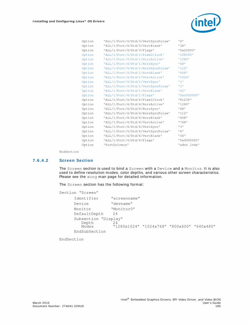
Intel® Embedded Graphics Drivers, EFI Video Driver, and Video BIOSMarch 2010 User’s GuideDocument Number: 274041-029US 185
Installing and Configuring Linux* OS Drivers
Option "ALL/1/Port/4/Dtd/3/VertSyncPulse" "6" Option "ALL/1/Port/4/Dtd/3/VertBlank" "38" Option "ALL/1/Port/4/Dtd/3/Flags" "0x20000" Option "ALL/1/Port/4/Dtd/1/PixelClock" "108000" Option "ALL/1/Port/4/Dtd/1/HorzActive" "1280" Option "ALL/1/Port/4/Dtd/1/HorzSync" "48" Option "ALL/1/Port/4/Dtd/1/HorzSyncPulse" "112" Option "ALL/1/Port/4/Dtd/1/HorzBlank" "408" Option "ALL/1/Port/4/Dtd/1/VertActive" "1024" Option "ALL/1/Port/4/Dtd/1/VertSync" "1" Option "ALL/1/Port/4/Dtd/1/VertSyncPulse" "3" Option "ALL/1/Port/4/Dtd/1/VertBlank" "42" Option "ALL/1/Port/4/Dtd/1/Flags" "0xc000000" Option "ALL/1/Port/4/Dtd/4/PixelClock" "81230" Option "ALL/1/Port/4/Dtd/4/HorzActive" "1280" Option "ALL/1/Port/4/Dtd/4/HorzSync" "48" Option "ALL/1/Port/4/Dtd/4/HorzSyncPulse" "112" Option "ALL/1/Port/4/Dtd/4/HorzBlank" "408" Option "ALL/1/Port/4/Dtd/4/VertActive" "768" Option "ALL/1/Port/4/Dtd/4/VertSync" "3" Option "ALL/1/Port/4/Dtd/4/VertSyncPulse" "6" Option "ALL/1/Port/4/Dtd/4/VertBlank" "34" Option "ALL/1/Port/4/Dtd/4/Flags" "0x4000000" Option "PortDrivers" "sdvo lvds"
EndSection
7.6.4.2 Screen Section
The Screen section is used to bind a Screen with a Device and a Monitor. It is also used to define resolution modes, color depths, and various other screen characteristics. Please see the xorg man page for detailed information.
The Screen section has the following format:
Section “Screen”Identifier “screenname”Device “devname”Monitor “Monitor0”DefaultDepth 24Subsection “Display”
Depth 24Modes “1280x1024” “1024x768” “800x600” “640x480”
EndSubSection
EndSection
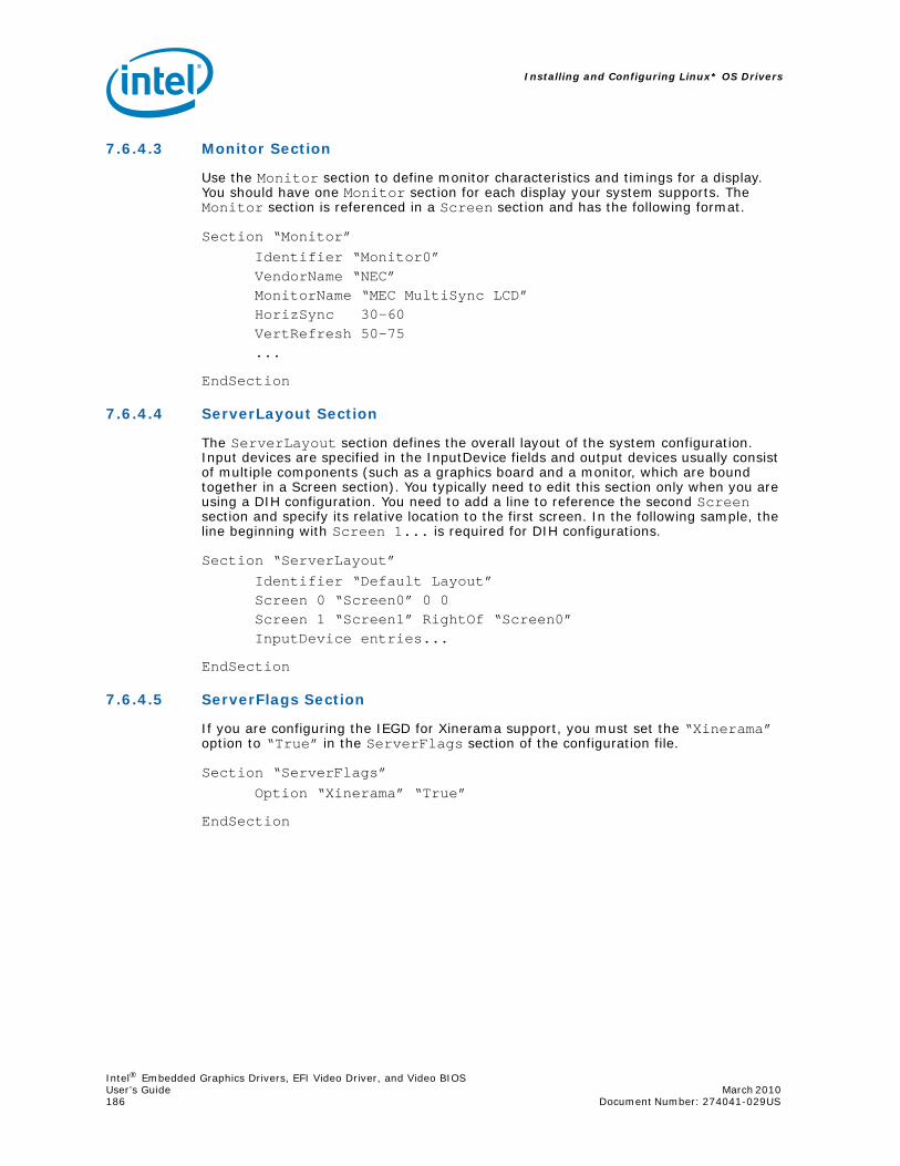
Installing and Configuring Linux* OS Drivers
Intel® Embedded Graphics Drivers, EFI Video Driver, and Video BIOSUser’s Guide March 2010 186 Document Number: 274041-029US
7.6.4.3 Monitor Section
Use the Monitor section to define monitor characteristics and timings for a display. You should have one Monitor section for each display your system supports. The Monitor section is referenced in a Screen section and has the following format.
Section “Monitor”Identifier “Monitor0”VendorName “NEC”MonitorName “MEC MultiSync LCD”HorizSync 30-60VertRefresh 50-75...
EndSection
7.6.4.4 ServerLayout Section
The ServerLayout section defines the overall layout of the system configuration. Input devices are specified in the InputDevice fields and output devices usually consist of multiple components (such as a graphics board and a monitor, which are bound together in a Screen section). You typically need to edit this section only when you are using a DIH configuration. You need to add a line to reference the second Screen section and specify its relative location to the first screen. In the following sample, the line beginning with Screen 1... is required for DIH configurations.
Section “ServerLayout”Identifier “Default Layout”Screen 0 “Screen0” 0 0Screen 1 “Screen1” RightOf “Screen0”InputDevice entries...
EndSection
7.6.4.5 ServerFlags Section
If you are configuring the IEGD for Xinerama support, you must set the “Xinerama” option to “True” in the ServerFlags section of the configuration file.
Section “ServerFlags”Option “Xinerama” “True”
EndSection
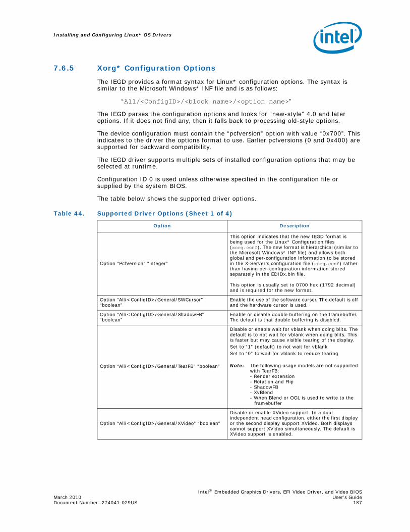
Intel® Embedded Graphics Drivers, EFI Video Driver, and Video BIOSMarch 2010 User’s GuideDocument Number: 274041-029US 187
Installing and Configuring Linux* OS Drivers
7.6.5 Xorg* Configuration Options
The IEGD provides a format syntax for Linux* configuration options. The syntax is similar to the Microsoft Windows* INF file and is as follows:
“All/<ConfigID>/<block name>/<option name>”
The IEGD parses the configuration options and looks for “new-style” 4.0 and later options. If it does not find any, then it falls back to processing old-style options.
The device configuration must contain the “pcfversion” option with value “0x700”. This indicates to the driver the options format to use. Earlier pcfversions (0 and 0x400) are supported for backward compatibility.
The IEGD driver supports multiple sets of installed configuration options that may be selected at runtime.
Configuration ID 0 is used unless otherwise specified in the configuration file or supplied by the system BIOS.
The table below shows the supported driver options.
Table 44. Supported Driver Options (Sheet 1 of 4)
Option Description
Option “PcfVersion” “integer”
This option indicates that the new IEGD format is being used for the Linux* Configuration files (xorg.conf). The new format is hierarchical (similar to the Microsoft Windows* INF file) and allows both global and per-configuration information to be stored in the X-Server’s configuration file (xorg.conf) rather than having per-configuration information stored separately in the EDIDx.bin file.
This option is usually set to 0700 hex (1792 decimal) and is required for the new format.
Option “All/<ConfigID>/General/SWCursor” “boolean”
Enable the use of the software cursor. The default is off and the hardware cursor is used.
Option “All/<ConfigID>/General/ShadowFB” “boolean”
Enable or disable double buffering on the framebuffer. The default is that double buffering is disabled.
Option “All/<ConfigID>/General/TearFB” “boolean”
Disable or enable wait for vblank when doing blits. The default is to not wait for vblank when doing blits. This is faster but may cause visible tearing of the display.Set to “1” (default) to not wait for vblankSet to “0” to wait for vblank to reduce tearing
Note: The following usage models are not supported with TearFB:- Render extension- Rotation and Flip- ShadowFB- XvBlend- When Blend or OGL is used to write to the framebuffer
Option “All/<ConfigID>/General/XVideo” “boolean”
Disable or enable XVideo support. In a dual independent head configuration, either the first display or the second display support XVideo. Both displays cannot support XVideo simultaneously. The default is XVideo support is enabled.
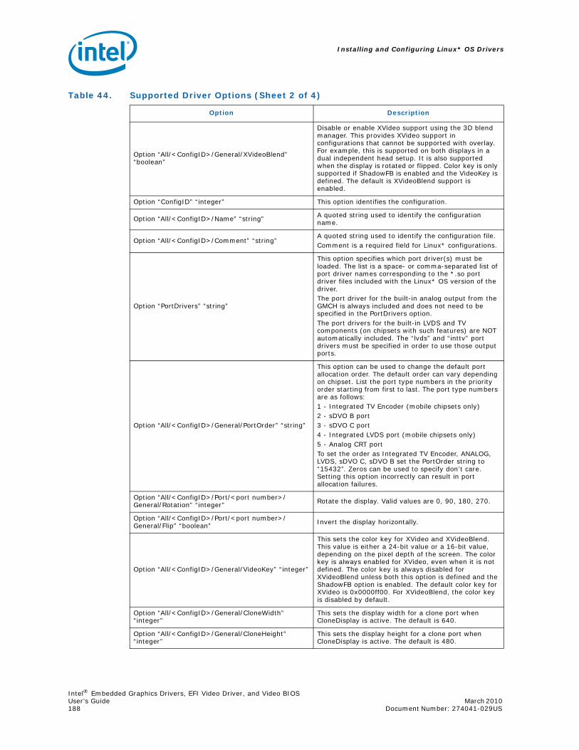
Installing and Configuring Linux* OS Drivers
Intel® Embedded Graphics Drivers, EFI Video Driver, and Video BIOSUser’s Guide March 2010 188 Document Number: 274041-029US
Option “All/<ConfigID>/General/XVideoBlend” “boolean”
Disable or enable XVideo support using the 3D blend manager. This provides XVideo support in configurations that cannot be supported with overlay. For example, this is supported on both displays in a dual independent head setup. It is also supported when the display is rotated or flipped. Color key is only supported if ShadowFB is enabled and the VideoKey is defined. The default is XVideoBlend support is enabled.
Option “ConfigID” “integer” This option identifies the configuration.
Option “All/<ConfigID>/Name” “string” A quoted string used to identify the configuration name.
Option “All/<ConfigID>/Comment” “string”A quoted string used to identify the configuration file.Comment is a required field for Linux* configurations.
Option “PortDrivers” “string”
This option specifies which port driver(s) must be loaded. The list is a space- or comma-separated list of port driver names corresponding to the *.so port driver files included with the Linux* OS version of the driver. The port driver for the built-in analog output from the GMCH is always included and does not need to be specified in the PortDrivers option.The port drivers for the built-in LVDS and TV components (on chipsets with such features) are NOT automatically included. The “lvds” and “inttv” port drivers must be specified in order to use those output ports.
Option “All/<ConfigID>/General/PortOrder” “string”
This option can be used to change the default port allocation order. The default order can vary depending on chipset. List the port type numbers in the priority order starting from first to last. The port type numbers are as follows:1 - Integrated TV Encoder (mobile chipsets only)2 - sDVO B port3 - sDVO C port4 - Integrated LVDS port (mobile chipsets only)5 - Analog CRT portTo set the order as Integrated TV Encoder, ANALOG, LVDS, sDVO C, sDVO B set the PortOrder string to “15432”. Zeros can be used to specify don’t care. Setting this option incorrectly can result in port allocation failures.
Option “All/<ConfigID>/Port/<port number>/General/Rotation” “integer” Rotate the display. Valid values are 0, 90, 180, 270.
Option “All/<ConfigID>/Port/<port number>/General/Flip” “boolean” Invert the display horizontally.
Option “All/<ConfigID>/General/VideoKey” “integer”
This sets the color key for XVideo and XVideoBlend. This value is either a 24-bit value or a 16-bit value, depending on the pixel depth of the screen. The color key is always enabled for XVideo, even when it is not defined. The color key is always disabled for XVideoBlend unless both this option is defined and the ShadowFB option is enabled. The default color key for XVideo is 0x0000ff00. For XVideoBlend, the color key is disabled by default.
Option “All/<ConfigID>/General/CloneWidth” “integer”
This sets the display width for a clone port when CloneDisplay is active. The default is 640.
Option “All/<ConfigID>/General/CloneHeight” “integer”
This sets the display height for a clone port when CloneDisplay is active. The default is 480.
Table 44. Supported Driver Options (Sheet 2 of 4)
Option Description

Intel® Embedded Graphics Drivers, EFI Video Driver, and Video BIOSMarch 2010 User’s GuideDocument Number: 274041-029US 189
Installing and Configuring Linux* OS Drivers
Option “All/<ConfigID>/General/CloneRefresh” “integer”
This sets the display vertical refresh rate for a clone port when CloneDisplay is active. The default is 60 Hz.
Option “All/<ConfigID>/Port/<port number>/General/EDID” “boolean”
Enable or disable reading of EDID data from the output port device. Note that if the EDID option is specified in the config file (xorg.conf), all per-port EDID options in the configuration are overwritten by the EDID option specified in the config file.
Option “All/<ConfigID>/General/Accel” “boolean” Enable 2D acceleration. Default is enabled.
Option “All/<ConfigID>/General/DRI” “boolean” Enable DRI support for OGL. Default if enabled.
Option “All/<ConfigID>/General/OverlayGammaCorrectR” “integer”
Gamma correction value for overlay (red) in 24i8f format.
Option “All/<ConfigID>/General/OverlayGammaCorrectG” “integer”
Gamma correction value for overlay (blue) in 24i8f format.
Option “All/<ConfigID>/General/OverlayGammaCorrectB” “integer”
Gamma correction value for overlay (green) in 24i8f format.
Option “All/<ConfigID>/General/OverlayBrightnessCorrect” “integer” Overlay brightness adjustments.
Option “All/<ConfigID>/General/OverlayContrastCorrect” “integer” Overlay contrast adjustments.
Option “All/<ConfigID>/General/OverlaySaturationCorrect” “integer” Overlay saturation adjustments.
Option “All/<ConfigID>/Port/<port number>/General/Name” “string”
A quoted string used to identify the port name, for example, “sdvo”.
Option “All/<ConfigID>/Port/<port number>/General/”EdidAvail “string”
Specifies how standard and user-defined modes are used when EDID is available. Default is 0.
Option “All/<ConfigID>/Port/<port number>/General/”EdidNotAvail “string”
Specifies how standard and user-defined modes are used when EDID is not available. Default is 0.
Option “All/<ConfigID>/Port/<port number>/General/CenterOff” “boolean”
When this option is enabled it DISABLES centering. Also, depending on the combination of “edid” + “user-dtd” + connected hardware, IEGD will add missing compatibility modes (6x4, 8x6, 10x7& 12x10) via centering. Use this option to disable this feature.
Option “All/<ConfigID>/Port/<port number>/Dvo/I2cDab” “string” I2c device address.
Option “All/<ConfigID>/Port/<port number>/Dvo/I2cSpeed” “string” I2c bus speed.
Option “All/<ConfigID>/Port/<port number>/Dvo/DdcSpeed” “string” DDC bus speed.
Option “All/<ConfigID>/Port/<port number>/Dvo/DdcDab” “string” DDC device address.
Option “All/<ConfigID>/Port/<port number>/Dtd/PixelClock” “integer” Pixel clock frequency (in kHz).
Option “All/<ConfigID>/Port/<port number>/Dtd/HorzActive” “integer” The active horizontal area (in pixels).
Option “All/<ConfigID>/Port/<port number>/Dtd/HorzSync” “integer” Starting pixel for horizontal sync pulse.
Option “All/<ConfigID>/Port/<port number>/Dtd/HorzSyncPulse” “integer” Width of the horizontal sync pulse (pixels).
Option “All/<ConfigID>/Port/<port number>/Dtd/HorzBlank” “integer” Width of the horizontal blanking period.
Option “All/<ConfigID>/Port/<port number>/Dtd/VertActive” “integer” The active vertical area (in pixels).
Table 44. Supported Driver Options (Sheet 3 of 4)
Option Description

Installing and Configuring Linux* OS Drivers
Intel® Embedded Graphics Drivers, EFI Video Driver, and Video BIOSUser’s Guide March 2010 190 Document Number: 274041-029US
7.6.6 Sample Dual Independent Head (DIH) Configuration
For dual independent head operation, several additional options must be set in the Device sections for each head. Both Device sections must specify the BusID, and the BusID must be the same for both devices. Each Device section must specify the Screen section that will associate the device with the Screen option.
BusID - B:F:S (Bus, Function, Slot)Screen - number
The example below shows a sample DIH configuration. Only the Device, Screen, and Server Layout sections of the configuration file are shown. For a complete example of a configuration file, see Figure 34 on page 181.
Option “All/<ConfigID>/Port/<port number>/Dtd/VertSync” “integer” Starting pixel for vertical sync pulse.
Option “All/<ConfigID>/Port/<port number>/Dtd/VertSyncPulse” “integer” Width of the vertical sync pulse (pixels).
Option “All/<ConfigID>/Port/<port number>/Dtd/VertBlank” “integer” Width of the vertical blanking period.
Option “All/<ConfigID>/Port/<port number>/Dtd/Flags” “integer” Additional timing information (interlaced).
Option “All/<ConfigID>/Port/<port number>/FpInfo/BkltMethod” “integer” Specifies the backlight method.
Option “All/<ConfigID>/Port/<port number>/FpInfo/BkltT1” “integer” Specifies backlight timing T1.
Option “All/<ConfigID>/Port/<port number>/FpInfo/BkltT2” “integer” Specifies backlight timing T2.
Option “All/<ConfigID>/Port/<port number>/FpInfo/BkltT3” “integer” Specifies backlight timing T3.
Option “All/<ConfigID>/Port/<port number>/FpInfo/BkltT4” “integer” Specifies backlight timing T4.
Option “All/<ConfigID>/Port/<port number>/FpInfo/BkltT5” “integer” Specifies backlight timing T5.
Table 44. Supported Driver Options (Sheet 4 of 4)
Option Description

Intel® Embedded Graphics Drivers, EFI Video Driver, and Video BIOSMarch 2010 User’s GuideDocument Number: 274041-029US 191
Installing and Configuring Linux* OS Drivers
Figure 35. Sample DIH Configuration
Section "Device"Identifier "IntelEGD-1"Driver "iegd"BusID "0:2:0"Screen 0VideoRam 32768
EndSection
Section "Device"Identifier "IntelEGD-2"Driver "iegd"BusID "0:2:0"Screen 1VideoRam 32768
EndSection
Section "Screen"Identifier "Screen 1"Device "IntelEGD-1"Monitor "Monitor1"DefaultDepth 24Subsection "Display"
Depth 8Modes "1280x1024" "1024x768" "800x600" "640x480"ViewPort 0 0
EndSubsectionSubsection "Display"
Depth 16Modes "1280x1024" "1024x768" "800x600" "640x480"ViewPort 0 0
EndSubsectionSubsection "Display"
Depth 24Modes "1280x1024" "1024x768" "800x600" "640x480"ViewPort 0 0
EndSubsection EndSection
Section "Screen"Identifier "Screen 2"Device "IntelEGD-2"Monitor "Monitor2"DefaultDepth 24Subsection "Display"
Depth 8Modes "1280x1024" "1024x768" "800x600" "640x480ViewPort 0 0
EndSubsection
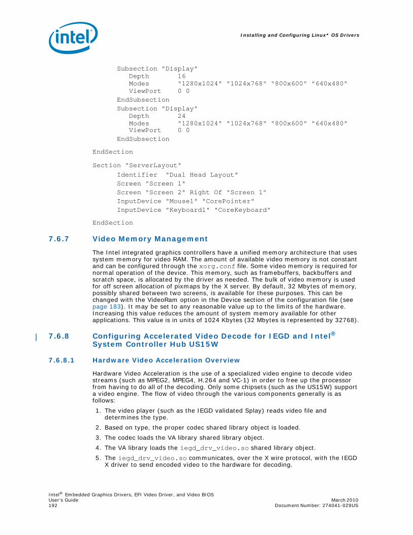
Installing and Configuring Linux* OS Drivers
Intel® Embedded Graphics Drivers, EFI Video Driver, and Video BIOSUser’s Guide March 2010 192 Document Number: 274041-029US
Subsection "Display"Depth 16Modes "1280x1024" "1024x768" "800x600" "640x480"ViewPort 0 0
EndSubsectionSubsection "Display"
Depth 24Modes "1280x1024" "1024x768" "800x600" "640x480"ViewPort 0 0
EndSubsection
EndSection
Section "ServerLayout"Identifier "Dual Head Layout"Screen "Screen 1"Screen "Screen 2" Right Of "Screen 1"InputDevice "Mouse1" "CorePointer"InputDevice "Keyboard1" "CoreKeyboard"
EndSection
7.6.7 Video Memory Management
The Intel integrated graphics controllers have a unified memory architecture that uses system memory for video RAM. The amount of available video memory is not constant and can be configured through the xorg.conf file. Some video memory is required for normal operation of the device. This memory, such as framebuffers, backbuffers and scratch space, is allocated by the driver as needed. The bulk of video memory is used for off screen allocation of pixmaps by the X server. By default, 32 Mbytes of memory, possibly shared between two screens, is available for these purposes. This can be changed with the VideoRam option in the Device section of the configuration file (see page 183). It may be set to any reasonable value up to the limits of the hardware. Increasing this value reduces the amount of system memory available for other applications. This value is in units of 1024 Kbytes (32 Mbytes is represented by 32768).
7.6.8 Configuring Accelerated Video Decode for IEGD and Intel® System Controller Hub US15W
7.6.8.1 Hardware Video Acceleration Overview
Hardware Video Acceleration is the use of a specialized video engine to decode video streams (such as MPEG2, MPEG4, H.264 and VC-1) in order to free up the processor from having to do all of the decoding. Only some chipsets (such as the US15W) support a video engine. The flow of video through the various components generally is as follows:
1. The video player (such as the IEGD validated Splay) reads video file and determines the type.
2. Based on type, the proper codec shared library object is loaded.
3. The codec loads the VA library shared library object.
4. The VA library loads the iegd_drv_video.so shared library object.
5. The iegd_drv_video.so communicates, over the X wire protocol, with the IEGD X driver to send encoded video to the hardware for decoding.

Intel® Embedded Graphics Drivers, EFI Video Driver, and Video BIOSMarch 2010 User’s GuideDocument Number: 274041-029US 193
Installing and Configuring Linux* OS Drivers
You can either use the provided binary of the libva library found in the appropriate Xorg/Xserver directory in the IEGD release or build it from the source. To build it, use the following steps:
1. Untar libva.tgz included in the IEGD driver package in the Extras folder.
2. Enter the following commands:./autogen.sh --prefix=/usrmakemake install
7.6.8.2 IEGD Driver
First install the IEGD Graphics Driver for Linux* per the appropriate installation instructions in Section 7.3. IEGD should be fully configured and running X properly before installing the VA Library.
7.6.8.3 Installing the VA Library (version 0.29)
Install the VA shared library object on the library path using the steps below.
1. Change to the IEGD directory for the X-Server version that matches your release where the library file is located (see Section 7.1 on page 149). For example, cd IEGD_10_3_1_Linux/driver/Xorg-xserver-1.4
2. Copy the libva.so.0.29.0 file to the /usr/lib folder using the following command:cp libva.so.0.29.0 /usr/lib
3. Create the library aliases:ln -s /usr/lib/libva.so.0.29.0 /usr/lib/libva.soln -s /usr/lib/libva.so.0.29.0 /usr/lib/libva.so.0
4. Set the Libva environment variable to point to the correct folder:Set LIBVA_DRIVERS_PATH to point to the location of the IEGD driver. The following is an example (with the BASH command shell):export LIBVA_DRIVERS_PATH=/usr/lib/xorg/modules/drivers
Your driver location may vary, so please use the path to where you installed the IEGD drivers. To make this “sticky” you may want to add this to your .profile, bashrc or whatever your distribution uses to store these variables.
7.6.8.4 Installing the IEGD Video Acceleration Driver
To install the provided Video Acceleration Driver (iegd_drv_video.so):
1. Change to the appropriate Xorg/Xserver directory where you unpacked the IEGD release.
2. Copy the driver to the directory where you installed the main IEGD driver from Section 7.3. For example: cp iegd_drv_video.so /usr/lib/xorg/modules/drivers
Note: Your actual directory will vary depending on your particular Linux* distribution.

Installing and Configuring Linux* OS Drivers
Intel® Embedded Graphics Drivers, EFI Video Driver, and Video BIOSUser’s Guide March 2010 194 Document Number: 274041-029US
7.6.8.5 Installing Helix Framework
Set up the Helix Framework environment to use accelerated video playback with the IEGD driver using the steps below.
1. Download helix-dbu-server and splay plug-ins from:https://helix-client.helixcommunity.org/releases
You will need to accept the Helix DNA Technology Binary Research Use License agreement and register an account before downloading the software.
a. Download the latest Splay Plug-ins files.Example: splay-plugin-atlas-01.2.0.tgz
b. Download the latest Helix DBUS Server files.Example: helix-dbus-server-0.6.0.tar.bz2
2. Untar splay-plugins.tgz and copy the contents to the directory /usr/lib/helix/splay
3. Untar helix-dbus-server-0.6.0.tar.bz2
4. Run make install from the helix-dbus-server-0.6.0 directory.
7.6.8.6 Installing Intel® Media Codec
The latest EVALUATION ONLY versions of the VA API enabled hardware accelerated codecs for Helix are available by contacting Intel through QuAD. After you have the codec package, follow these steps to install it:
1. Untar the codec package.
2. Copy libipp_hx_*.so to /usr/lib/helix/splay
3. Remove /usr/lib/helix/splay/mpgfformat.so
4. Remove /usr/lib/helix/splay/h264dec.so
5. Remove /usr/lib/helix/splay/mp4vrender.so
6. Remove /usr/lib/helix/splay/wmvrender.so
7. Remove /usr/lib/helix/splay/wmv9.so
7.6.8.7 Playing Video
The video player application used must support the Helix plug-in framework. A sample player (splay) is included and known to work. The splay application is located in the /usr/lib/helix/splay directory.
To play a video, enter the following command:
— /usr/lib/helix/splay/splay -l /usr/lib/helix/splay <Video file>where <Video file> is replaced with an actual file name.

Intel® Embedded Graphics Drivers, EFI Video Driver, and Video BIOSMarch 2010 User’s GuideDocument Number: 274041-029US 195
Installing and Configuring Linux* OS Drivers
7.6.8.8 Troubleshooting
1. If the “splay” application quits silently, try removing the helix configuration files ~/.helix, ~/.hxplayerrc, and ~/.realplayerrc.
2. Check the codec version numbers using the script get_lib_version.sh included with the codecs. The output should be:
libipp_hx_ac3ad.so -> ipp_hx_version:20080822:1.8.8.22libipp_hx_h264vd.so -> ipp_hx_version:20080822:1.8.8.22libipp_hx_mp2sp.so -> ipp_hx_version:20080822:1.8.8.22libipp_hx_mp2vd.so -> ipp_hx_version:20080822:1.8.8.22libipp_hx_mp4vd.so -> ipp_hx_version:20080822:1.8.8.22libipp_hx_vc1vd.so -> ipp_hx_version:20080401:1.8.8.22
3. If you receive the following message when you try to play video:libva: Trying to open /usr/X11R6/lib/modules/dri/iegd_drv_video.solibva: va_openDriver() returns -1
make sure the LIBVA_DRIVERS_PATH environment variable is set to the location where you installed the iegd_drv_video.so file. Typically this would be /usr/lib/xorg/modules/drivers.
7.6.9 Graphics Port Initialization
When used with a graphic chipset that supports multiple graphics pipelines, the driver supports multiple screens and Xinerama. This support is enabled by creating additional Device sections for each additional graphics device on the PCI bus. The driver locates the first device on the bus and associates it with the device section that matches (or one that does not specify a busID). This becomes the primary display. If the chipset supports multiple display pipes, and the config file specifies two Device sections and two Screen sections, the driver attempts to operate in a dual-independent head mode. After all the graphics devices and device sections have been matched up, the driver attempts to allocate any remaining output ports and attach them to the primary graphics device. For example:
• Two pipes and two ports allows for dual independent displays.
• One pipe and two ports allows for a cloned display (915GV special case).

Installing and Configuring Linux* OS Drivers
Intel® Embedded Graphics Drivers, EFI Video Driver, and Video BIOSUser’s Guide March 2010 196 Document Number: 274041-029US
7.6.10 OpenGL Support
The IEGD supports OpenGL* for the following Intel chipsets:
• Intel® Atom™ Processor 400 and 500 Series
• Intel® Q45/G41/G45 Express chipset
• Intel® GM45/GL40/GS45 Express chipset
• Intel® System Controller Hub US15W/US15WP/WPT chipset
• Intel® Q35 Express chipset
• Mobile Intel® GLE960/GME965 Express chipset
• Intel® Q965 Express chipset
• Mobile Intel® 945GSE Express chipset
• Mobile Intel® 945GME Express chipset
• Intel® 945G Express chipset
• Mobile Intel® 915GME Express chipsets
• Intel® 915GV Express chipsets
• Mobile Intel® 910GMLE Express chipset
The OpenGL implementation for IEGD consists of three components.
• libGL: This is the shared library that implements the OpenGL and GLX APIs. It is linked by all OpenGL applications.
• iegd.ko: This is the Direct Rendering Manager (DRM). It is a kernel module that provides the OpenGL application with the permissions necessary to directly access the DMA buffers used by libGL.
• X Server: The existing IEGD X server driver has been enhanced to communicate with libGL.
Installing the IEGD OpenGL driver provides a fully hardware accelerated implementation of the OpenGL library to applications. This implementation makes use of a Direct Rendering technology, which allows the client to directly write to DMA buffers that are used by the graphics hardware.
Due to the use of direct rendering technology, system designers should take special care to ensure that only trusted clients are allowed to use the OpenGL library. A malicious application could otherwise use direct rendering to destabilized the graphics hardware or, in theory, elevate their permissions on the system.
A system designer can control the access to the direct rendering functionality by limiting the access to the DRI device file located at:
/dev/dri/card0The permissions on this device are set by the X-Server using the information provided in the “DRI” section of the configuration file.

Intel® Embedded Graphics Drivers, EFI Video Driver, and Video BIOSMarch 2010 User’s GuideDocument Number: 274041-029US 197
Installing and Configuring Linux* OS Drivers
7.6.10.1 OpenGL Installation
To install the IEGD libGL onto a system, copy the library binary from the package to the standard location and then link the files as follows:
• For gen4:
copy libGLgn4.so and then runln -sfv libGLgn4.so libGL.so.1.2ln -sfv libGL.so.1.2 libGL.so.1ln -sfv libGL.so.1.2 libGL.so
• For gen3:
copy libGLgn3.so and then runln -sfv libGLgn3.so libGL.so.1.2ln -sfv libGL.so.1.2 libGL.so.1ln -sfv libGL.so.1.2 libGL.so
• For US15W:
copy libGL_ga.so.1.2and then runln -sfv libGL_ga.so libGL.so.1.2ln -sfv libGL.so.1.2 libGL.so.1ln -sfv libGL.so.1.2 libGL.so
After you complete the copy and link steps above, compile and install the Direct Rendering Manager (DRM) kernel module from the sources provided. Lastly, enable the DRI option in the X server's configuration file. Refer to the sections below for details on specific operating systems.
Linux*
The OGL/ES application requires the following share libraries:
• libEGL.so
• libGLESv1_CM.so (ES1.1)
• libGLESv2.so (ES2.0)
• iegd_dri.so
• egl_xdri.so
• egl_iegd_dri.so
• libEGLdri.so
A typical OpenGL ES program will link with libEGL.so and either libGLESv1_CM.so or libGLESv2.so. Then libEGL.so will link to libEGLdri.so or egl_xdri.so or egl_iegd_dri.so. Then, libEGLdri.so/egl_xdri.so/egl_iegd_dri.so will link to iegd_dri.so.
Windows CE*
The application needs to link to the following import libraries to compile:
• libOpenGL.lib - OpenGL
• libGLES_CM.lib - ES 1.1
• libGLESv2.lib - ES2.0

Installing and Configuring Linux* OS Drivers
Intel® Embedded Graphics Drivers, EFI Video Driver, and Video BIOSUser’s Guide March 2010 198 Document Number: 274041-029US
The application then needs to be able to access the following dynamic link libraries during runtime:
• libOpenGL.dll - OpenGL
• libGLES_CM.dll - ES 1.1
• libGLESv2.dll - ES2.0
Windows XP*
The application needs to link to the following import libraries to compile:
• libGLES_CM.lib - ES 1.1
• libGLESv2.lib - ES2.0
The application then needs to be able to access the following dynamic link libraries during runtime:
• libGLES_CM.dll - ES 1.1
• libGLESv2.dll - ES2.0
The OpenGL driver is automatically installed during the normal driver installation.
Note: The system likely has a version of libGL already installed. You may want to make a backup copy of the existing library before installing the IEGD library.
Installation Steps
1. cd IEGD_x_Linux/driver/<directory>where <directory> is whichever X-Server or Xorg driver directory is being used. For example, for Fedora 7 it would be driver/Xorg-xserver-1.3.
Note: The locations and commands may be different for a specific Linux distribution.
2. cp iegd_dri.so /usr/lib/dri
Note: If you find that you are still using software rendering and hardware rendering is not being used, copy the iegd_dri.so to /usr/X11R6/lib/dri.
3. cp libGLgn#.so /usr/lib/libGL.so.1.2
— For 910GMLE, 915GME, 915GV, 945GME, 945GSE, 945GUse libGLgn3.so
— For Q965, GLE960/GME965, Q45, GM45/GL40/GS45, Q35Use libGLgn4.so
— US15W/US15WP/WPTUse libGL_ga.so.1.2
Note: For Fedora 10, perform the following steps. For other operating systems, continue with step 4.
cd /libln -sfv libexpat.so.1.5.3 libexpat.so.0
4. cd /usr/lib
5. ln -sfv /usr/lib/libGL.so.1.2 libGL.so
6. ln -sfv /usr/lib/libGL.so.1.2 libGL.so.1
7. ldconfig

Intel® Embedded Graphics Drivers, EFI Video Driver, and Video BIOSMarch 2010 User’s GuideDocument Number: 274041-029US 199
Installing and Configuring Linux* OS Drivers
Note: Skip steps 8 and 9 if you are using the IKM method detailed in Section 7.4.
8. cd IEGD_10_3_1_Linux/IKM/Drm
9. makeThis will build and install the kernel module for the currently running kernel. If another kernel is installed or used, this step must be performed again.
10.depmod -Ae
11. Restart the X-Server or restart the system.
To Enable or Disable Multi-Sample Anti-Aliasing (MSAA)
If you would like to enable or disable Multi-Sample Anti-Aliasing on the Intel US15W, enter the following commands into the terminal:
• Enable: export _GL_FSAA_MODE=4
• Disable: export _GL_FSAA_MODE=0 or export _GL_FSAA_MODE=1
7.6.10.2 OpenGL Use Considerations
Allocation of Mipmaps and Memory Usage
Under normal circumstances the OpenGL driver will allocate all mip levels for a texture at allocation time. This is due to the fact that the OpenGL API allows an application to make use of the mips without first conveying an intention to do so. All mips are therefore available all the time.
The IEGD OpenGL driver has a special-case scenario to prevent the allocation of mips when the application can ensure that they will never be populated or used. On some hardware configurations this can save 50% on texture memory usage. To enable this feature, the application should do the following:
Using glTexParameter*(), set the GL_TEXTURE_MAX_LEVEL parameter to 0 before populating the texture (before any call to glTexImage2D()). This will prevent mips 1-N from being allocated but will not prevent them from being used. If the mips are inadvertently used, the results are undefined.
7.6.10.3 OpenGL ES
OpenGLES headers are downloadable from http://www.khronos.org/opengles/spec/.
EGL headers are downloadable from http://www.khronos.org/registry/egl/.
See also Appendix D, “2D/3D API Support”.
7.6.11 Sample Advanced EDID Configurations for Linux* OS
The edid_avail and edid_not_avail parameters control the available timings for any display. The edid_avail parameter is used when EDID information is read from the display. If the driver is unable to read EDID information from the display or if the edid parameter in the config file is set to “0” (disable), then the settings of the edid_not_avail parameter are used. Please see Section 3.0, “Platform Configuration Using CED” on page 29 and CED online help.
There is an edid option that can be placed in the xorg.conf files that controls the behavior of the overall driver, and there are also EDID settings within CED that control the behavior on each port (edid, edid_avail, and edid_not_avail). The combination of these settings determines how the driver behaves. The table below shows various configurations and the expected behavior of the driver.
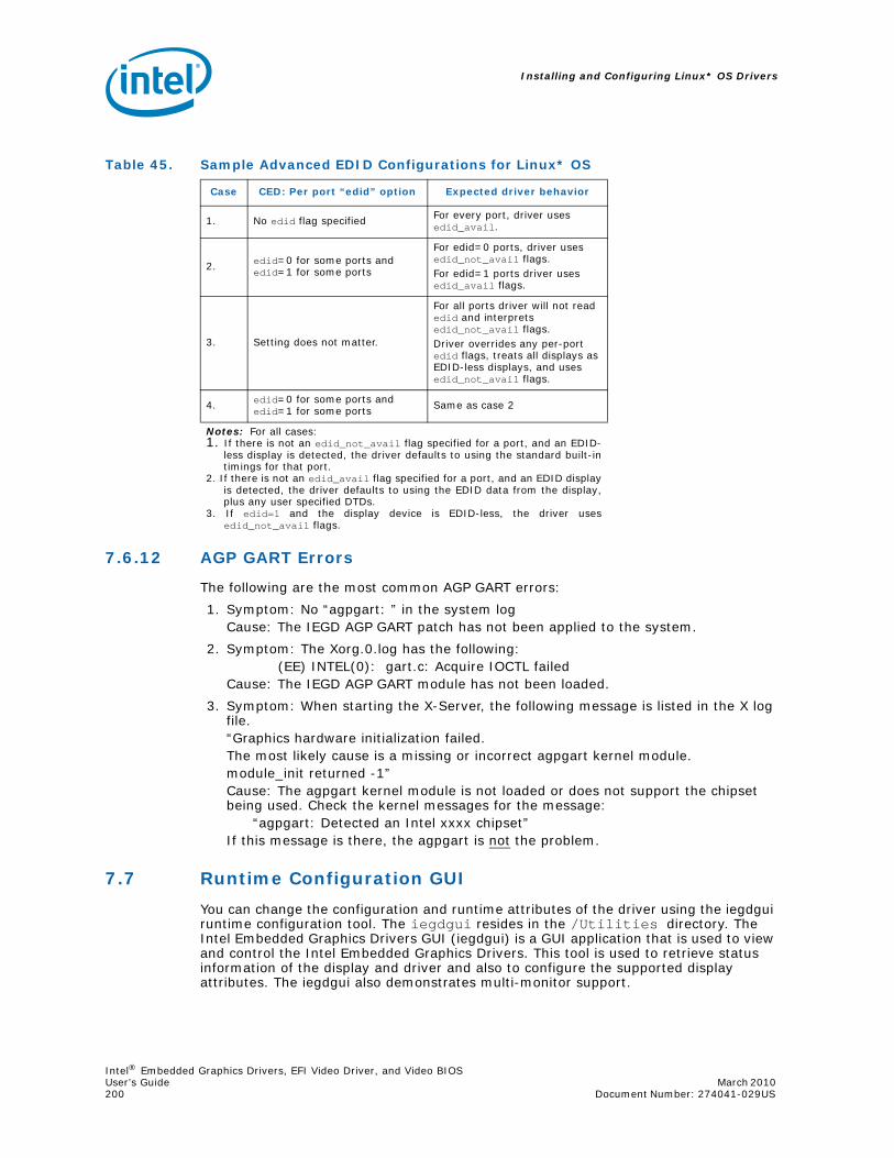
Installing and Configuring Linux* OS Drivers
Intel® Embedded Graphics Drivers, EFI Video Driver, and Video BIOSUser’s Guide March 2010 200 Document Number: 274041-029US
7.6.12 AGP GART Errors
The following are the most common AGP GART errors:
1. Symptom: No “agpgart: ” in the system logCause: The IEGD AGP GART patch has not been applied to the system.
2. Symptom: The Xorg.0.log has the following:(EE) INTEL(0): gart.c: Acquire IOCTL failed
Cause: The IEGD AGP GART module has not been loaded.
3. Symptom: When starting the X-Server, the following message is listed in the X log file.“Graphics hardware initialization failed.The most likely cause is a missing or incorrect agpgart kernel module.module_init returned -1”Cause: The agpgart kernel module is not loaded or does not support the chipset being used. Check the kernel messages for the message:
“agpgart: Detected an Intel xxxx chipset”If this message is there, the agpgart is not the problem.
7.7 Runtime Configuration GUI
You can change the configuration and runtime attributes of the driver using the iegdgui runtime configuration tool. The iegdgui resides in the /Utilities directory. The Intel Embedded Graphics Drivers GUI (iegdgui) is a GUI application that is used to view and control the Intel Embedded Graphics Drivers. This tool is used to retrieve status information of the display and driver and also to configure the supported display attributes. The iegdgui also demonstrates multi-monitor support.
Table 45. Sample Advanced EDID Configurations for Linux* OS
Case CED: Per port “edid” option Expected driver behavior
1. No edid flag specified For every port, driver uses edid_avail.
2. edid=0 for some ports and edid=1 for some ports
For edid=0 ports, driver uses edid_not_avail flags. For edid=1 ports driver uses edid_avail flags.
3. Setting does not matter.
For all ports driver will not read edid and interprets edid_not_avail flags. Driver overrides any per-port edid flags, treats all displays as EDID-less displays, and uses edid_not_avail flags.
4. edid=0 for some ports and edid=1 for some ports Same as case 2
Notes: For all cases: 1. If there is not an edid_not_avail flag specified for a port, and an EDID-
less display is detected, the driver defaults to using the standard built-intimings for that port.
2. If there is not an edid_avail flag specified for a port, and an EDID displayis detected, the driver defaults to using the EDID data from the display,plus any user specified DTDs.
3. If edid=1 and the display device is EDID-less, the driver usesedid_not_avail flags.

Intel® Embedded Graphics Drivers, EFI Video Driver, and Video BIOSMarch 2010 User’s GuideDocument Number: 274041-029US 201
Installing and Configuring Linux* OS Drivers
7.7.1 iegdgui Setup
To run the iegdgui, you need to ensure that the X-Server has been configured to use the IEGD. See Section 7.6.1, “Configuration Overview” on page 179 for details on configuring and installing the IEGD.
You need GTK+ and libglade, which are part of the Linux* distribution and should already be installed.
Ensure that the LD_LIBRARY_PATH environment variable points to the X11R6 library. If it does not, type the following command:
export LD_LIBRARY_PATH=/usr/X11R6/libEnsure the iegdgui is executable by changing directories to .../IEGD_10_3_1_Linux/Utilities and running the following command:
ls -l iegdgui
Executable permissions should be set for all three Linux* groups (user, group, world) and should look like this:
rwxr_xr_x iegdgui ...
If the permissions do not contain an “x” for each group, change the permissions using the following command:
chmod +rwx iegdgui
After you have completed this step, the IEGD can be launched.
7.7.2 Using the iegdgui Runtime Configuration Utility
The iegdgui application provides four tabs: Driver Info, Display Config, Display Attributes, and Color Correction.
• Driver Info: Contains the driver information.
• Display Config: Contains current display information and allows configuration of display configurations, display resolutions for primary and secondary displays and enabling/disabling of a specified port.
• Display Attributes: Contains the supported Port Driver (PD) attributes and allows configuration of PD attributes.
• Color Correction: Contains current color-correction information for the framebuffer and overlay. Using this tab, you can change the framebuffer and overlay color settings.
The figure below shows the Driver info tab.
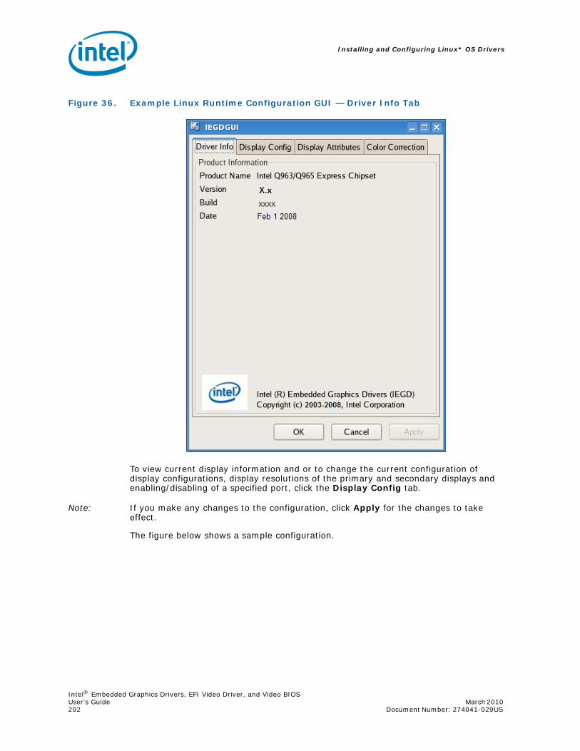
Installing and Configuring Linux* OS Drivers
Intel® Embedded Graphics Drivers, EFI Video Driver, and Video BIOSUser’s Guide March 2010 202 Document Number: 274041-029US
To view current display information and or to change the current configuration of display configurations, display resolutions of the primary and secondary displays and enabling/disabling of a specified port, click the Display Config tab.
Note: If you make any changes to the configuration, click Apply for the changes to take effect.
The figure below shows a sample configuration.
Figure 36. Example Linux Runtime Configuration GUI — Driver Info Tab

Intel® Embedded Graphics Drivers, EFI Video Driver, and Video BIOSMarch 2010 User’s GuideDocument Number: 274041-029US 203
Installing and Configuring Linux* OS Drivers
The Display Status section of the above dialog shows the current configuration for the Primary and Secondary displays.
In the Display Configuration section of the dialog, select the required display configuration in the Display Config drop-down list. This allows the user to choose between Single, Twin, Clone and Extended for all connected ports. A maximum of two ports per display configuration is currently allowed.
In the Primary Mode and Secondary Mode sections of the dialog, you can change display resolutions via the Resolution drop-down list.
In the Display Settings section of the dialog, you can view and change the settings for a port and then rotate and flip the display via the appropriate drop-down lists:
• Port: Allows you to select the required port.
• Port Status: Allows you to enable or disable the selected port.
Note: If you change any configuration settings in the Display Config dialog box, click Apply for the changes to take effect.
Figure 37. Example Linux* Runtime Configuration GUI — Display Config Tab

Installing and Configuring Linux* OS Drivers
Intel® Embedded Graphics Drivers, EFI Video Driver, and Video BIOSUser’s Guide March 2010 204 Document Number: 274041-029US
To view or change the attributes for a port, click the Display Attributes tab. The figure below shows a sample configuration. Please see Appendix B for detailed information on port driver attributes.
Note: If you make any changes to the port driver attributes, click Apply for the changes to take effect.
To view and change color corrections, click the Color Correction tab. The figures above and below show sample Color Correction tab screens for Framebuffer and Overlay, color correction values for which are shown in Table 30 and Table 31.
Note: If you make any changes to the color-correction attributes, click Apply for the changes to take effect.
Figure 38. Example Linux* Runtime Configuration GUI — Display Attributes Tab

Intel® Embedded Graphics Drivers, EFI Video Driver, and Video BIOSMarch 2010 User’s GuideDocument Number: 274041-029US 205
Installing and Configuring Linux* OS Drivers
The following steps present an example color-correction procedure:
a. Select Framebuffer in the Surface section and select the appropriate port for the color correction to be applied to or select Overlay in the Surface section for color correction to be applied to the overlay.
b. Select the required color to be corrected in the Color section.
c. Select the required color attribute to be corrected in the Gamma Correction section.
d. Click Restore Defaults to restore the default values.
Figure 39. Example Linux* Runtime Configuration GUI — Color Correction Tab (Framebuffer)
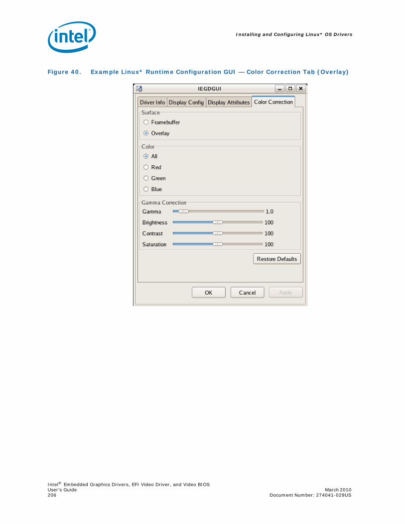
Installing and Configuring Linux* OS Drivers
Intel® Embedded Graphics Drivers, EFI Video Driver, and Video BIOSUser’s Guide March 2010 206 Document Number: 274041-029US
Figure 40. Example Linux* Runtime Configuration GUI — Color Correction Tab (Overlay)

Intel® Embedded Graphics Drivers, EFI Video Driver, and Video BIOSMarch 2010 User’s GuideDocument Number: 274041-029US 207
Example INF File
Appendix A Example INF File
;*******************************************************************************; Filename: iegd.inf; $Revision$; $Id$; $Source$;; Copyright (c) 2009 Intel Corporation. All rights reserved.;;*******************************************************************************
[Version] Signature="$WINDOWS NT$" Class=DisplayClassGUID={4D36E968-E325-11CE-BFC1-08002BE10318} Provider=%Intel% ;CatalogFile=iegd.catDriverVer = 12/17/2009,10.3.0
;===============================================================================[SourceDisksNames]1=%DiskDesc%,,,""
[SourceDisksFiles]iegdmini.sys = 1iegdckey.vp = 1iegdmsys.vp = 1iegdcagt.cpa = 1iegdcagt.vp = 1iegddis.dll = 1iegd3dg3.dll = 1iegd3dg4.dll = 1iegd3dga.dll = 1iegdglga.dll = 1libGLES_CM.dll = 1libGLESv2.dll = 1analog.sys = 1lvds.sys = 1sdvo.sys = 1tv.sys = 1hdmi.sys = 1sdvo.vp = 1hdmi.vp = 1analog.vp = 1lvds.vp = 1tv.vp = 1;===============================================================================[DestinationDirs]DefaultDestDir = 11; System directoryiegd.Display_nap = 11iegd.Display_gn4 = 11iegd.Display_plb = 11iegd.OpenGL_plb = 11

Example INF File
Intel® Embedded Graphics Drivers, EFI Video Driver, and Video BIOSUser’s Guide March 2010 208 Document Number: 274041-029US
iegd.Miniport = 12; Drivers directoryiegd.Copp1 = 12iegd.PortDrvs_nap = 12iegd.PortDrvs_gn4 = 12iegd.PortDrvs_plb = 12
;===============================================================================[Manufacturer]%Intel%=Intel.Mfg
;===============================================================================[Intel.Mfg]%Intel% %i915GD0% = iegd_nap, PCI\VEN_8086&DEV_2582%Intel% %i915GD1% = iegd_nap, PCI\VEN_8086&DEV_2782%Intel% %i915AL0% = iegd_nap, PCI\VEN_8086&DEV_2592%Intel% %i915AL1% = iegd_nap, PCI\VEN_8086&DEV_2792%Intel% %i945LP0% = iegd_nap, PCI\VEN_8086&DEV_2772%Intel% %i945LP1% = iegd_nap, PCI\VEN_8086&DEV_2776%Intel% %i945CT0% = iegd_nap, PCI\VEN_8086&DEV_27A2%Intel% %i945CT1% = iegd_nap, PCI\VEN_8086&DEV_27A6%Intel% %i945WB0% = iegd_nap, PCI\VEN_8086&DEV_27AE%Intel% %i35BL0% = iegd_nap, PCI\VEN_8086&DEV_29C2%Intel% %i35BL1% = iegd_nap, PCI\VEN_8086&DEV_29C3%Intel% %i35BL0A2% = iegd_nap, PCI\VEN_8086&DEV_29B2%Intel% %i35BL1A2% = iegd_nap, PCI\VEN_8086&DEV_29B3%Intel% %i3150DT0% = iegd_nap, PCI\VEN_8086&DEV_A001%Intel% %i3150DT1% = iegd_nap, PCI\VEN_8086&DEV_A002%Intel% %i3150MB0% = iegd_nap, PCI\VEN_8086&DEV_A011%Intel% %i3150MB1% = iegd_nap, PCI\VEN_8086&DEV_A012
%Intel% %i965BW0% = iegd_gn4, PCI\VEN_8086&DEV_2982%Intel% %i965BW1% = iegd_gn4, PCI\VEN_8086&DEV_2983%Intel% %iG9650% = iegd_gn4, PCI\VEN_8086&DEV_29A2%Intel% %iG9651% = iegd_gn4, PCI\VEN_8086&DEV_29A3%Intel% %iQ9650% = iegd_gn4, PCI\VEN_8086&DEV_2992%Intel% %iQ9651% = iegd_gn4, PCI\VEN_8086&DEV_2993%Intel% %i946GZ0% = iegd_gn4, PCI\VEN_8086&DEV_2972%Intel% %i946GZ1% = iegd_gn4, PCI\VEN_8086&DEV_2973%Intel% %i965GM0% = iegd_gn4, PCI\VEN_8086&DEV_2A02%Intel% %i965GM1% = iegd_gn4, PCI\VEN_8086&DEV_2A03%Intel% %i965GME0% = iegd_gn4, PCI\VEN_8086&DEV_2A12%Intel% %i965GME1% = iegd_gn4, PCI\VEN_8086&DEV_2A13%Intel% %iGM450% = iegd_gn4, PCI\VEN_8086&DEV_2A42%Intel% %iGM451% = iegd_gn4, PCI\VEN_8086&DEV_2A43%Intel% %iG450% = iegd_gn4, PCI\VEN_8086&DEV_2E22%Intel% %iG451% = iegd_gn4, PCI\VEN_8086&DEV_2E23%Intel% %iG410% = iegd_gn4, PCI\VEN_8086&DEV_2E32%Intel% %iG411% = iegd_gn4, PCI\VEN_8086&DEV_2E33%Intel% %iELK0% = iegd_gn4, PCI\VEN_8086&DEV_2E02%Intel% %iELK1% = iegd_gn4, PCI\VEN_8086&DEV_2E03%Intel% %iQ450% = iegd_gn4, PCI\VEN_8086&DEV_2E12%Intel% %iQ451% = iegd_gn4, PCI\VEN_8086&DEV_2E13
%Intel% %i900G0% = iegd_plb, PCI\VEN_8086&DEV_8108
;===============================================================================[iegd_nap.GeneralConfigData]MaximumNumberOfDevices = 2MaximumDeviceMemoryConfiguration = 256
[iegd_gn4.GeneralConfigData]MaximumNumberOfDevices = 2MaximumDeviceMemoryConfiguration = 512
1. Certified Output Protection Protocol (COPP) is a proprietary product of Microsoft Corporation.

Intel® Embedded Graphics Drivers, EFI Video Driver, and Video BIOSMarch 2010 User’s GuideDocument Number: 274041-029US 209
Example INF File
[iegd_plb.GeneralConfigData]MaximumNumberOfDevices = 2MaximumDeviceMemoryConfiguration = 256
;===============================================================================[iegd_nap]CopyFiles = iegd.Miniport, iegd.Display_nap, iegd.PortDrvs_nap, iegd.Copp
[iegd_gn4]CopyFiles = iegd.Miniport, iegd.Display_gn4, iegd.PortDrvs_gn4, iegd.Copp
[iegd_plb]CopyFiles = iegd.Miniport, iegd.Display_plb, iegd.OpenGL_plb, iegd.PortDrvs_plb, iegd.Copp
;===============================================================================[iegd.Miniport]iegdmini.sys
[iegd.Copp]iegdckey.vpiegdmsys.vpsdvo.vphdmi.vpanalog.vplvds.vptv.vpiegdcagt.cpaiegdcagt.vp
[iegd.Display_nap]iegddis.dlliegd3dg3.dll
[iegd.Display_gn4]iegddis.dlliegd3dg4.dll
[iegd.Display_plb]iegddis.dlliegd3dga.dll
[iegd.OpenGL_plb]iegdglga.dlllibGLES_CM.dlllibGLESv2.dll
[iegd.PortDrvs_nap]analog.syssdvo.syslvds.systv.sys
[iegd.PortDrvs_gn4]analog.syssdvo.syslvds.syshdmi.sys
[iegd.PortDrvs_plb]sdvo.syslvds.sys
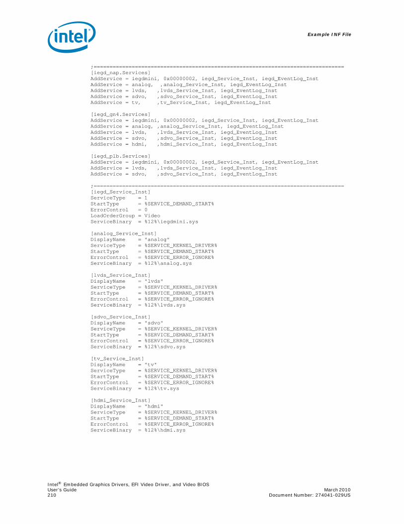
Example INF File
Intel® Embedded Graphics Drivers, EFI Video Driver, and Video BIOSUser’s Guide March 2010 210 Document Number: 274041-029US
;===============================================================================[iegd_nap.Services]AddService = iegdmini, 0x00000002, iegd_Service_Inst, iegd_EventLog_InstAddService = analog, ,analog_Service_Inst, iegd_EventLog_InstAddService = lvds, ,lvds_Service_Inst, iegd_EventLog_InstAddService = sdvo, ,sdvo_Service_Inst, iegd_EventLog_InstAddService = tv, ,tv_Service_Inst, iegd_EventLog_Inst
[iegd_gn4.Services]AddService = iegdmini, 0x00000002, iegd_Service_Inst, iegd_EventLog_InstAddService = analog, ,analog_Service_Inst, iegd_EventLog_InstAddService = lvds, ,lvds_Service_Inst, iegd_EventLog_InstAddService = sdvo, ,sdvo_Service_Inst, iegd_EventLog_InstAddService = hdmi, ,hdmi_Service_Inst, iegd_EventLog_Inst
[iegd_plb.Services]AddService = iegdmini, 0x00000002, iegd_Service_Inst, iegd_EventLog_InstAddService = lvds, ,lvds_Service_Inst, iegd_EventLog_InstAddService = sdvo, ,sdvo_Service_Inst, iegd_EventLog_Inst
;===============================================================================[iegd_Service_Inst]ServiceType = 1StartType = %SERVICE_DEMAND_START%ErrorControl = 0LoadOrderGroup = VideoServiceBinary = %12%\iegdmini.sys
[analog_Service_Inst]DisplayName = "analog"ServiceType = %SERVICE_KERNEL_DRIVER%StartType = %SERVICE_DEMAND_START%ErrorControl = %SERVICE_ERROR_IGNORE%ServiceBinary = %12%\analog.sys
[lvds_Service_Inst]DisplayName = "lvds"ServiceType = %SERVICE_KERNEL_DRIVER%StartType = %SERVICE_DEMAND_START%ErrorControl = %SERVICE_ERROR_IGNORE%ServiceBinary = %12%\lvds.sys
[sdvo_Service_Inst]DisplayName = "sdvo"ServiceType = %SERVICE_KERNEL_DRIVER%StartType = %SERVICE_DEMAND_START%ErrorControl = %SERVICE_ERROR_IGNORE%ServiceBinary = %12%\sdvo.sys
[tv_Service_Inst]DisplayName = "tv"ServiceType = %SERVICE_KERNEL_DRIVER%StartType = %SERVICE_DEMAND_START%ErrorControl = %SERVICE_ERROR_IGNORE%ServiceBinary = %12%\tv.sys
[hdmi_Service_Inst]DisplayName = "hdmi"ServiceType = %SERVICE_KERNEL_DRIVER%StartType = %SERVICE_DEMAND_START%ErrorControl = %SERVICE_ERROR_IGNORE%ServiceBinary = %12%\hdmi.sys

Intel® Embedded Graphics Drivers, EFI Video Driver, and Video BIOSMarch 2010 User’s GuideDocument Number: 274041-029US 211
Example INF File
;===============================================================================[iegd_EventLog_Inst]AddReg = iegd_EventLog_AddReg
[iegd_EventLog_AddReg]HKR,,EventMessageFile,0x00020000,"%SystemRoot%\System32\IoLogMsg.dll;%SystemRoot%\System32\drivers\iegdmini.sys"HKR,,TypesSupported,0x00010001,7
;===============================================================================[iegd_nap.SoftwareSettings]AddReg = iegd_SoftwareDeviceSettings_nap
[iegd_gn4.SoftwareSettings]AddReg = iegd_SoftwareDeviceSettings_gn4
[iegd_plb.SoftwareSettings]AddReg = iegd_SoftwareDeviceSettings_plbAddReg = iegd_ICDSoftwareSettings
;===============================================================================[iegd_SoftwareDeviceSettings_nap]HKR,, InstalledDisplayDrivers, %REG_MULTI_SZ%, iegddisHKR,, MultiFunctionSupported, %REG_MULTI_SZ%, 1HKR,, VgaCompatible, %REG_DWORD%, 0HKR,, PcfVersion, %REG_DWORD%, 0x0700
HKR,, ConfigId, %REG_DWORD%, 1
HKR,, PortDrivers, %REG_SZ%, "analog"
;-------------------------------------------------------------------------------[iegd_ICDSoftwareSettings]HKLM, "SOFTWARE\Microsoft\Windows NT\CurrentVersion\OpenGLDrivers\iegddis", DLL, %REG_SZ%, iegdglgaHKLM, "SOFTWARE\Microsoft\Windows NT\CurrentVersion\OpenGLDrivers\iegddis", DriverVersion, %REG_DWORD%, 0x00000001HKLM, "SOFTWARE\Microsoft\Windows NT\CurrentVersion\OpenGLDrivers\iegddis", Flags, %REG_DWORD%, 0x00000001HKLM, "SOFTWARE\Microsoft\Windows NT\CurrentVersion\OpenGLDrivers\iegddis", Version, %REG_DWORD%, 0x00000002
;===============================================================================[Strings]
;----------------------------------------------------------------------; Localizable Strings;----------------------------------------------------------------------Intel="Intel Corporation"DiskDesc="Embedded Installation"
i915GD0="915G/915GV/910GL Embedded Graphics Chipset Function 0"i915GD1="915G/915GV/910GL Embedded Graphics Chipset Function 1"i915AL0="915GM/915GMS/915GME/910GML/910GMLE Embedded Graphics Chipset Function 0"i915AL1="915GM/915GMS/915GME/910GML/910GMLE Embedded Graphics Chipset Function 1"i945LP0="945G Embedded Graphics Chipset Function 0"i945LP1="945G Embedded Graphics Chipset Function 1"i945CT0="945GM Embedded Graphics Chipset Function 0"i945CT1="945GM Embedded Graphics Chipset Function 1"i945WB0="945GME/945GSE Embedded Graphics Chipset Function 0"i35BL0="Q35 Embedded Graphics Chipset Function 0"i35BL1="Q35 Embedded Graphics Chipset Function 1"i35BL0A2="Q35 Embedded Graphics Chipset Function 0"i35BL1A2="Q35 Embedded Graphics Chipset Function 1"i3150DT0="GMA 3150 Embedded Graphics Chipset Function 0"i3150DT1="GMA 3150 Embedded Graphics Chipset Function 1"

Example INF File
Intel® Embedded Graphics Drivers, EFI Video Driver, and Video BIOSUser’s Guide March 2010 212 Document Number: 274041-029US
i3150MB0="GMA 3150 Embedded Graphics Chipset Function 0"i3150MB1="GMA 3150 Embedded Graphics Chipset Function 1"
i965BW0="965G Embedded Graphics Chipset Function 0"i965BW1="965G Embedded Graphics Chipset Function 1"iG9650="G965 Embedded Graphics Chipset Function 0"iG9651="G965 Embedded Graphics Chipset Function 1"iQ9650="Q963/Q965 Embedded Graphics Chipset Function 0"iQ9651="Q963/Q965 Embedded Graphics Chipset Function 1"i946GZ0="946GZ Embedded Graphics Chipset Function 0"i946GZ1="946GZ Embedded Graphics Chipset Function 1"i965GM0="GM965 Embedded Graphics Chipset Function 0"i965GM1="GM965 Embedded Graphics Chipset Function 1"i965GME0="GLE960/GME965 Embedded Graphics Chipset Function 0"i965GME1="GLE960/GME965 Embedded Graphics Chipset Function 1"iGM450="GM45/GS45/GL40 Embedded Graphics Chipset Function 0"iGM451="GM45/GS45/GL40 Embedded Graphics Chipset Function 1"iG450="G45 Embedded Graphics Chipset Function 0"iG451="G45 Embedded Graphics Chipset Function 1"iG410="G41 Embedded Graphics Chipset Function 0"iG411="G41 Embedded Graphics Chipset Function 1"iELK0="Q45 Embedded Graphics Chipset Function 0"iELK1="Q45 Embedded Graphics Chipset Function 1"iQ450="Q45 Embedded Graphics Chipset Function 0"iQ451="Q45 Embedded Graphics Chipset Function 1"
i900G0="US15 Embedded Graphics Chipset Function 0"
;----------------------------------------------------------------------; Non Localizable Strings;----------------------------------------------------------------------SERVICE_BOOT_START = 0x0SERVICE_SYSTEM_START = 0x1SERVICE_AUTO_START = 0x2SERVICE_DEMAND_START = 0x3SERVICE_DISABLED = 0x4
SERVICE_KERNEL_DRIVER = 0x1
SERVICE_ERROR_IGNORE = 0x0; Continue on driver load failSERVICE_ERROR_NORMAL = 0x1; Display warn, but continueSERVICE_ERROR_SEVERE = 0x2; Attempt LastKnownGoodSERVICE_ERROR_CRITICAL = 0x3; Attempt LastKnownGood, BugCheck
REG_EXPAND_SZ = 0x00020000REG_MULTI_SZ = 0x00010000REG_DWORD = 0x00010001REG_SZ = 0x00000000

Intel® Embedded Graphics Drivers, EFI Video Driver, and Video BIOSMarch 2010 User’s GuideDocument Number: 274041-029US 213
Port Driver Attributes
Appendix B Port Driver Attributes
B.1 Standard Port Driver Attributes
Port drivers are modules within the IEGD driver suite that control GMCH-specific modules such as GMCH LVDS, GMCH TV or add-on modules to GMCH. The table below lists the attributes available to port drivers. Some of these standard attributes can be customized for specific port drivers and are detailed in the following sections of this appendix.
In the following tables, device-specific (non-standard) attributes are highlighted in gray.
• “Internal LVDS Port Driver Attributes (Mobile chipsets only)” on page 215
• “CRT (Analog) Port Driver Attributes” on page 216
• “HDMI Port Driver Attributes” on page 216
• “Chrontel CH7307 Port Driver Attributes” on page 218
• “Chrontel CH7308 Port Driver Attributes” on page 218
• “Chrontel CH7315/CH7319/CH7320 Port Driver Attributes” on page 219
• “Chrontel CH7317 Port Driver Attributes” on page 219
• “Chrontel CH7022 Port Driver Attributes” on page 220
• “Silicon Image SiI 1362/SiI 1364 Port Driver DVI Attributes” on page 221
Note: Not all standard attributes are supported by all port drivers. Please see the following sections for details on the specific attributes supported by each port driver. Flat panel settings are specified via the FPINFO options of the configuration; please see Table 24 in Section 3.0.
Table 46. Standard Port Driver Attributes (Sheet 1 of 3)
Attribute Name Attribute ID Number Description
BRIGHTNESS 0 Brightness adjustment.
CONTRAST 1 Contrast adjustment.
HUE 2 Hue adjustment.
FLICKER 3 Setting to reduce flicker.
HPOSITION 4 Controls the horizontal position of the display.
VPOSITION 5 Controls the vertical position of the display.
HSCALE 6 Horizontal scaling ratio.
VSCALE 7 Vertical scaling ratio.
TVFORMAT 8 TV formats are device-specific.
DISPLAY TYPE 9 Allows selection of different displays for multi-display devices. This attribute is device-specific.

Port Driver Attributes
Intel® Embedded Graphics Drivers, EFI Video Driver, and Video BIOSUser’s Guide March 2010 214 Document Number: 274041-029US
LUMA FILTER 10 TV Luma Filter adjustment.
CHROMA FILTER 11 ChromaFilter adjustment.
TEXT FILTER 12 Text Filter adjustment.
TV OUTPUT TYPE 14 TV output types. This attribute is device-specific.
SATURATION 15 Saturation adjustment.
PANEL FIT 18 Panel fitting. Yes or no.
SCALING RATIO 19 Output Scaling. Device-specific.
FP BACKLIGHT ENABLE 20 Enable flat panel backlight.
PANEL DEPTH 26 Can be either 18 or 24. 18 specifies 6-bit output per color, 24 specifies 8-bit output per color.
DUAL CHANNEL PANEL 27 Is it a dual channel panel or not? Takes 0 or 1.
GANG MODE 28 For achieving a Gang mode output using two digital ports.
GANG MODE EVEN ODD 29
Gang display even or odd. This attribute is to be set along with Gang mode (28). This mode (Gang Mode Even Odd) puts even pixels on one digital port and odd pixels on the other, and needs to be selected based on the display panel used.
SHARPNESS 31 Sharpness.
HWCONFIG 32 Hardware Configuration for sDVO encoders that support multiple configurations.
HORZFILTER 33 Horizontal Filter.
VERTFILTER 34 Vertical Filter.
FRAME BUFFER GAMMA 35 Framebuffer gamma correction.
FRAME BUFFER BRIGHTNESS 36 Framebuffer brightness.
FRAME BUFFER CONTRAST 37 Framebuffer contrast.
2D FLICKER 39 Two-dimension flicker.
ADAPTIVE FLICKER 40 Adaptive flicker.
HORIZONTAL OVERSCAN 41 Horizontal overscan.
VERTICAL OVERSCAN 42 Vertical overscan.
SPREAD SPECTRUM CLOCKING 43 Spectrum Clocking
DOT_CRAWL 44 Dot crawl affects the edges of color and manifests itself as moving dots of color along these edges.
DITHER 45 Dither setting
PANEL PROTECT HSYNC 46 Horizontal sync panel protection
PANEL PROTECT VSYNC 47 Vertical sync panel protection
PANEL PROTECT PIXCLK 48 Pixel clock protection
LVDS PANEL TYPE 49 This is used to select SPWG vs. OpenLDI panel types. 0-SPWG 1-OpenLDI.
VGA 2X IMAGE 57 Controls VGA image in Gang mode.
TEXT ENHANCEMENT 58 Controls text tuning.
Table 46. Standard Port Driver Attributes (Sheet 2 of 3)
Attribute Name Attribute ID Number Description

Intel® Embedded Graphics Drivers, EFI Video Driver, and Video BIOSMarch 2010 User’s GuideDocument Number: 274041-029US 215
Port Driver Attributes
B.2 Port Driver Attributes
This section provides the supported attributes for each of the port drivers.
B.2.1 Internal LVDS Port Driver Attributes (Mobile chipsets only)
MAINTAIN ASPECT RATIO 59 This controls scaled image to match source image aspect ratio or full screen image.
FIXED TIMING 60 This indicates whether the attached display is a fixed timing display.
INTENSITY 70
This attribute provides a method to control the backlight intensity. It is not a method to turn on backlight but provides a way to adjust its value in percentages from 0% to 100%
Table 46. Standard Port Driver Attributes (Sheet 3 of 3)
Attribute Name Attribute ID Number Description
Table 47. Internal LVDS Port Driver Attributes (Sheet 1 of 2)
Attribute Name Attribute ID Description Possible Ranges
PANELDEPTH 26 Specify Panel Depth based on connected panel.
Default is 18, however, on some GMCH chipsets 24-bit also is supported. For example, GM965 supports both 18 and 24-bit outputs.
DUALCHANNEL 27 Single or Dual Channel Panel 0 = Single1 = DualDefault is 0.
Spread Spectrum Clocking 43 Spectrum Clocking
3-9 for US15W4-13 for GM45/GL40/GS450-15 for other chipsetsDefault = 7Step = 1
Note: This setting changes the EMI characteristics, which can be measured with tuning equipment. The change will not necessarily be visible in the display.
DITHER 45 On and off Dithering
Dither=0 for 24-bit panelsDither=1 for 18-bit panels Default:• dither = 1 for 18-bit panels • dither = 0 for 24-bit panels.
LVDS Panel Type 49 LVDS panel connector.
0 = SPWG formatted LVDS output (default)1 = OpenLDI unbalanced color mapping outputDefault = 0
FIXED TIMING 60This indicates whether attached display is a fixed timing display.
0 = on1 = off

Port Driver Attributes
Intel® Embedded Graphics Drivers, EFI Video Driver, and Video BIOSUser’s Guide March 2010 216 Document Number: 274041-029US
B.2.2 CRT (Analog) Port Driver Attributes
Note: The analog port driver is included in the driver by default, unlike other port drivers available for selection as part of the driver configuration. It is a dynamically loadable port driver instead of being statically linked into the main driver, for example iegdmini.sys for Windows* or iegd_drv.so for Linux*.
B.2.3 HDMI Port Driver Attributes
B.2.3.1 Audio
The IEGD package does not include an HDMI audio driver, so you must obtain and install the driver yourself. The HDMI audio driver needs to support Intel HD Audio to be compatible with IEGD. You must also obtain Microsoft patch KB888111 to enable HDMI audio. IEGD supports only the Windows* HDMI audio driver.
INTENSITY 70
This attribute provides a method to control the backlight intensity. It is not a method to turn on backlight but provides a way to adjust its value in percentages from 0% to 100%
Valid range is 0-100%.Default is 0.
INVERTER FREQUENCY 71
A method of controlling the backlight. It determines the number of time base events in total for a complete cycle of modulated backlight control.
Valid range is 0-65535 Hz.Default is 0.Typical value is300 – 1000.
BACKLIGHT LEGACY MODE 72
A method for controlling whether to use legacy mode for PWM duty cycle. Legacy mode is where the PWM duty cycle will be calculated using a combination of Backlight duty cycle and Legacy backlight Control (LBPC). In non-legacy mode, it will be calculated using Backlight duty cycle only.
Valid values are 0 for non-legacy mode or 1 for legacy mode.Default is 0.
Table 48. CRT (Analog) Port Driver Attributes
Attribute Name Attribute ID Description Possible Ranges
FIXED TIMING 60Set this attribute if the attached display supports only one timing.
0 = Not a fixed timing display.1 = Fixed timing display. Default is 0.
DETECT METHOD 32769 Controls display detection for the CRT.
0 = Uses DDC method first then Analog sense to detect the display1 = DDC method only (Digital Sense method) by reading EDID2 = Analog Sense onlyDefault is 0.
Table 47. Internal LVDS Port Driver Attributes (Sheet 2 of 2)
Attribute Name Attribute ID Description Possible Ranges

Intel® Embedded Graphics Drivers, EFI Video Driver, and Video BIOSMarch 2010 User’s GuideDocument Number: 274041-029US 217
Port Driver Attributes
B.2.3.2 SDVO-HDMI (CH7315)
IEGD supports only one type of SDVO-HDMI encoder, which is CH7315. SDVO-B cannot coexist with HDMI-B; SDVO-C cannot coexist with HDMI-C.
SDVO takes precedence over the HDMI port driver. If no SDVO encoder is available HDMI is automatically loaded by default (only in the GM45 Express chipset).
B.2.3.3 Internal HDMI
Internal HDMI is available only for the GM45 Express chipset. Only one HDMI port has audio at any one time. The first port in the port order has audio while the second port would have only display without audio.
Only one HDMI port has HDCP at any one time. The first port to receive a request for HDCP has HDCP enabled only in that port.
B.2.3.4 HDCP
HDCP is supported through the Certified Output Protection Protocol* (COPP) interface in Windows.
B.2.4 Internal TV Out Port Driver Attributes (Mobile chipsets only)
Table 49. Internal TV Out Port Driver Attributes (Sheet 1 of 2)
Attribute Name Attribute ID Description Possible Ranges
BRIGHTNESS 0 Screen brightness 0-100. Default is 50.
CONTRAST 1 Color contrast 0-7. Default is 3.
HUE 2 Hue adjustment 0-100. Default is 0.
TV FLICK FILTER 3
TV Flicker Filter. The higher the value, the higher the amount of flicker filtering and text enhancement.
0-1000. Default is 999.
H POSITION 4
Horizontal Position. Increasing the value moves the image to the right and decreasing the value moves the image to the left.
0-511. Default is 64.
V POSITION 5
Vertical Position. The value represents the TV line number relative to the VGA vertical sync. Increasing the value moves the image down and decreasing the value moves the image up.
0-511. Default is 0.

Port Driver Attributes
Intel® Embedded Graphics Drivers, EFI Video Driver, and Video BIOSUser’s Guide March 2010 218 Document Number: 274041-029US
B.2.5 Chrontel CH7307 Port Driver Attributes
The table below shows the attributes for the Chrontel CH7307* port driver.
Note: For flat panel backlight timing settings, please see Table 24 in Section 3.11.
B.2.6 Chrontel CH7308 Port Driver Attributes
The table below shows the attributes for the Chrontel CH7308* port driver.
Note: For FPINFO panel width, height, and backlight timing settings, please see Table 24 in Section 3.11.
TV FORMAT 8 TV formats are device-specific. Default is NTSC-M (1).
TV OUTPUT 14
TV output types. This attribute is device-specific. Note: TV output types are
limited to S-Video and Composite for the VBIOS.
Default is S-VIDEO (2).
OVERSCAN/SCALING RATIO 19 Output Scaling. 0-1000. Default is 350.
Table 49. Internal TV Out Port Driver Attributes (Sheet 2 of 2)
Attribute Name Attribute ID Description Possible Ranges
Table 50. Chrontel CH7307 Port Driver Attributes
Attribute Name Attribute ID Description Possible Ranges
Spread Spectrum Clocking 43 Spectrum clocking0-15Default = 0Step = 1
FIXED TIMING 60This indicates whether attached display is a fixed timing display.
0 = on1 = off
Table 51. Chrontel CH7308 Port Driver Attributes (Sheet 1 of 2)
Attribute Name Attribute ID Description Possible Ranges
LVDS Color Depth 26 Panel depth18 = 18 bits24 = 24 bitsDefault = 18
DUAL_CHANNEL 27 Dual-channel pane Default - 0
Spread Spectrum Clocking 43 Spectrum Clocking0-15Default = 7Step = 1
Dither 45 Dither setting Default = 0
HSync Panel Protection 46 Horizontal sync panel protection Default = 0
VSync Panel Protection 47 Vertical sync panel protection Default = 0

Intel® Embedded Graphics Drivers, EFI Video Driver, and Video BIOSMarch 2010 User’s GuideDocument Number: 274041-029US 219
Port Driver Attributes
B.2.7 Chrontel CH7315/CH7319/CH7320 Port Driver Attributes
Note: For flat panel backlight timing settings, please see Table 24 in Section 3.11.
B.2.8 Chrontel CH7317 Port Driver Attributes
The table below shows the attributes for the Chrontel CH7317 port driver.
Pixel Clock Protection 48 Pixel clock protection Default = 0
LVDS Panel Type 49 LVDS panel connector.
0 = SPWG formatted LVDS output (default)1 = OpenLDI unbalanced color mapping outputDefault = 0
Text Enhancement 58 Controls text tuning. 0-4.
Fixed Timing 60This indicates whether attached display is a fixed timing display.
0 = on1 = off
Table 52. Chrontel CH7315/CH7319/CH7320 Port Driver Attributes
Attribute Name Attribute ID Description Possible Ranges
Fixed Timing 60This indicates whether attached display is a fixed timing display.
0 = on1 = off
Table 51. Chrontel CH7308 Port Driver Attributes (Sheet 2 of 2)
Attribute Name Attribute ID Description Possible Ranges
Table 53. Chrontel CH7317 Port Driver Attributes
Attribute Name Attribute ID Description Possible Ranges
VGA Bypass 9
Enables VGA bypass. To enable VGA Bypass, this configuration setting line must exist in the configuration file with the value of 2. Attribute 9 is used to enable selection of several possible display types based on what was supported on an SDVO device as defined in SDVO specifications. Default value of 2 represent VGA display.
1) Enable VGA Bypass
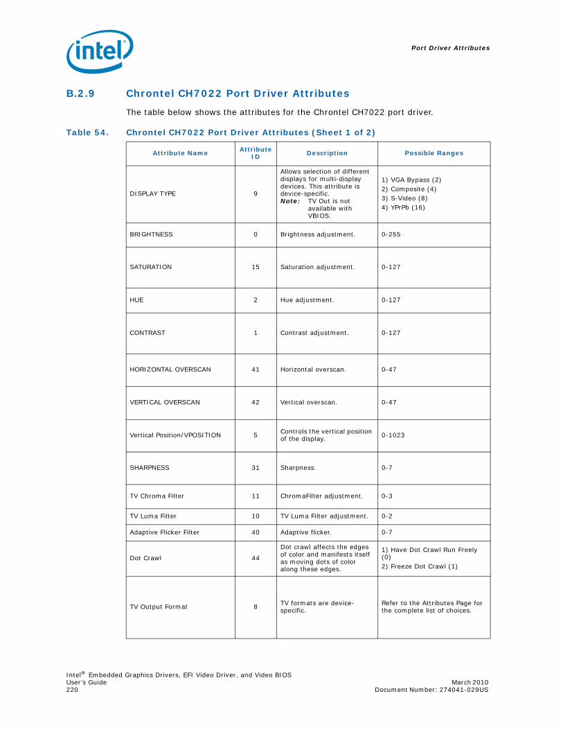
Port Driver Attributes
Intel® Embedded Graphics Drivers, EFI Video Driver, and Video BIOSUser’s Guide March 2010 220 Document Number: 274041-029US
B.2.9 Chrontel CH7022 Port Driver Attributes
The table below shows the attributes for the Chrontel CH7022 port driver.
Table 54. Chrontel CH7022 Port Driver Attributes (Sheet 1 of 2)
Attribute Name Attribute ID Description Possible Ranges
DISPLAY TYPE 9
Allows selection of different displays for multi-display devices. This attribute is device-specific.Note: TV Out is not
available with VBIOS.
1) VGA Bypass (2)2) Composite (4) 3) S-Video (8)4) YPrPb (16)
BRIGHTNESS 0 Brightness adjustment. 0-255
SATURATION 15 Saturation adjustment. 0-127
HUE 2 Hue adjustment. 0-127
CONTRAST 1 Contrast adjustment. 0-127
HORIZONTAL OVERSCAN 41 Horizontal overscan. 0-47
VERTICAL OVERSCAN 42 Vertical overscan. 0-47
Vertical Position/VPOSITION 5 Controls the vertical position of the display. 0-1023
SHARPNESS 31 Sharpness. 0-7
TV Chroma Filter 11 ChromaFilter adjustment. 0-3
TV Luma Filter 10 TV Luma Filter adjustment. 0-2
Adaptive Flicker Filter 40 Adaptive flicker. 0-7
Dot Crawl 44
Dot crawl affects the edges of color and manifests itself as moving dots of color along these edges.
1) Have Dot Crawl Run Freely (0)2) Freeze Dot Crawl (1)
TV Output Format 8 TV formats are device-specific.
Refer to the Attributes Page for the complete list of choices.

Intel® Embedded Graphics Drivers, EFI Video Driver, and Video BIOSMarch 2010 User’s GuideDocument Number: 274041-029US 221
Port Driver Attributes
B.2.10 Silicon Image SiI 1362/SiI 1364 Port Driver DVI Attributes
Note: For flat panel backlight timing settings, please see Table 24 in Section 3.11.
Analog Source 52 VGA
1) No Data (0) 2) Analog Source (1)3) Pre-recorded Packaged (2)4) Not Analog Pre-recorded (3)
Scan Information 53 TV attributes are device specific.
1) No Data (0) 2) Overscanned (1) 3) Under scanned (2)
Picture Aspect Ratio 54 The relative horizontal and vertical sizes.
1) No Data (0) 2) 4:3 (1) 3) 16:9 (2)
Active Format Ratio 55 Output ratio.
1) No Data (0)2) Active Format (1)3) Square Pixels(8)4) 4:3 Center (9)5) 16:9 Center (10)6) 14:9 Center (11) 7) 16:9 Letterbox (Top)(2)8) 14:9 Letterbox (Top)(3)9) 16:9 Letterbox (Center)10) 4:3 (with shoot and protect 14:9 center) 11) 16:9 (with shoot and protect 14:9 center) (10610) 12) 16:9 (with shoot and protect 4:3 center)
Table 55. Silicon Image SiI 1362/SiI 1364 Port Driver Attributes
Attribute Name Attribute ID Description Possible Ranges
FIXED TIMING 60This indicates whether attached display is a fixed timing display.
0 = on1 = off
Table 54. Chrontel CH7022 Port Driver Attributes (Sheet 2 of 2)
Attribute Name Attribute ID Description Possible Ranges

Port Driver Attributes
Intel® Embedded Graphics Drivers, EFI Video Driver, and Video BIOSUser’s Guide March 2010 222 Document Number: 274041-029US
B.3 Chipset and Port Driver-specific Installation Information
B.3.1 Default Search Order
Note: See more information pertaining to port order in the description for “Port Devices (Available Ports, Port Order)” on page 38.
B.3.2 Default GPIO Pin Pair Assignments
Table 56. Default Search Order
Chipset Default Search Order
Intel®PNV ANALOG, LVDS
Intel® Q45/G41/G45 ANALOG, sDVOB, sDVOC
Intel® GM45/GL40/GS45 ANALOG, sDVOB, sDVOC, LVDS
Intel® US15W/US15WP/WPT LVDS, sDVOB
Intel® Q35 ANALOG, sDVOB, sDVOC
Intel® GLE960/GME965 ANALOG, sDVOB, sDVOC, LVDS
Intel® Q965 ANALOG, sDVOB, sDVOC
Intel® 945GME/945GSE ANALOG, sDVOB, sDVOC, LVDS
Intel® 945G ANALOG, sDVOB, sDVOC
Intel® 915GV ANALOG, sDVOB, sDVOC
Intel® 915GME ANALOG, sDVOB, sDVOC, LVDS
Intel® 910GMLE ANALOG, sDVOB, sDVOC, LVDS
Table 57. Default GPIO Pin Pair Assignments
ChipsetDefault GPIO Pin Pair for EDID
sDVO/A sDVOB sDVOC LVDS
Intel®PNV N/A 4 2 2
Intel® Q45/G41/G45 N/A 4 4 N/A
Intel® GM45/GL40/GS45 N/A 4 4 2
Intel® US15W/WP/WPT N/A 4 4 2
Intel® Q35 N/A 4 4 N/A
Intel® GLE960/GME965 N/A 4 4 2
Intel® Q965 N/A 4 4 N/A
Intel® 945GME/945GSE N/A 4 4 2
Intel® 945G N/A 4 4 N/A
Intel® 915GV N/A 4 4 N/A
Intel® 915GM N/A 4 4 2
Intel® 910GMLE N/A 4 4 2
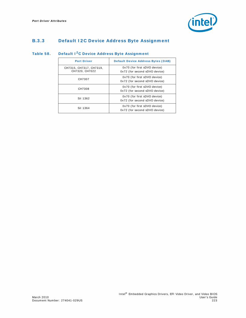
Intel® Embedded Graphics Drivers, EFI Video Driver, and Video BIOSMarch 2010 User’s GuideDocument Number: 274041-029US 223
Port Driver Attributes
B.3.3 Default I2C Device Address Byte Assignment
Table 58. Default I2C Device Address Byte Assignment
Port Driver Default Device Address Bytes (DAB)
CH7315, CH7317, CH7319, CH7320, CH7022
0x70 (for first sDVO device)0x72 (for second sDVO device)
CH73070x70 (for first sDVO device)
0x72 (for second sDVO device)
CH73080x70 (for first sDVO device)
0x72 (for second sDVO device)
SiI 13620x70 (for first sDVO device)
0x72 (for second sDVO device)
SiI 13640x70 (for first sDVO device)
0x72 (for second sDVO device)

This page is intentionally left blank.
Port Driver Attributes
Intel® Embedded Graphics Drivers, EFI Video Driver, and Video BIOSUser’s Guide March 2010 224 Document Number: 274041-029US
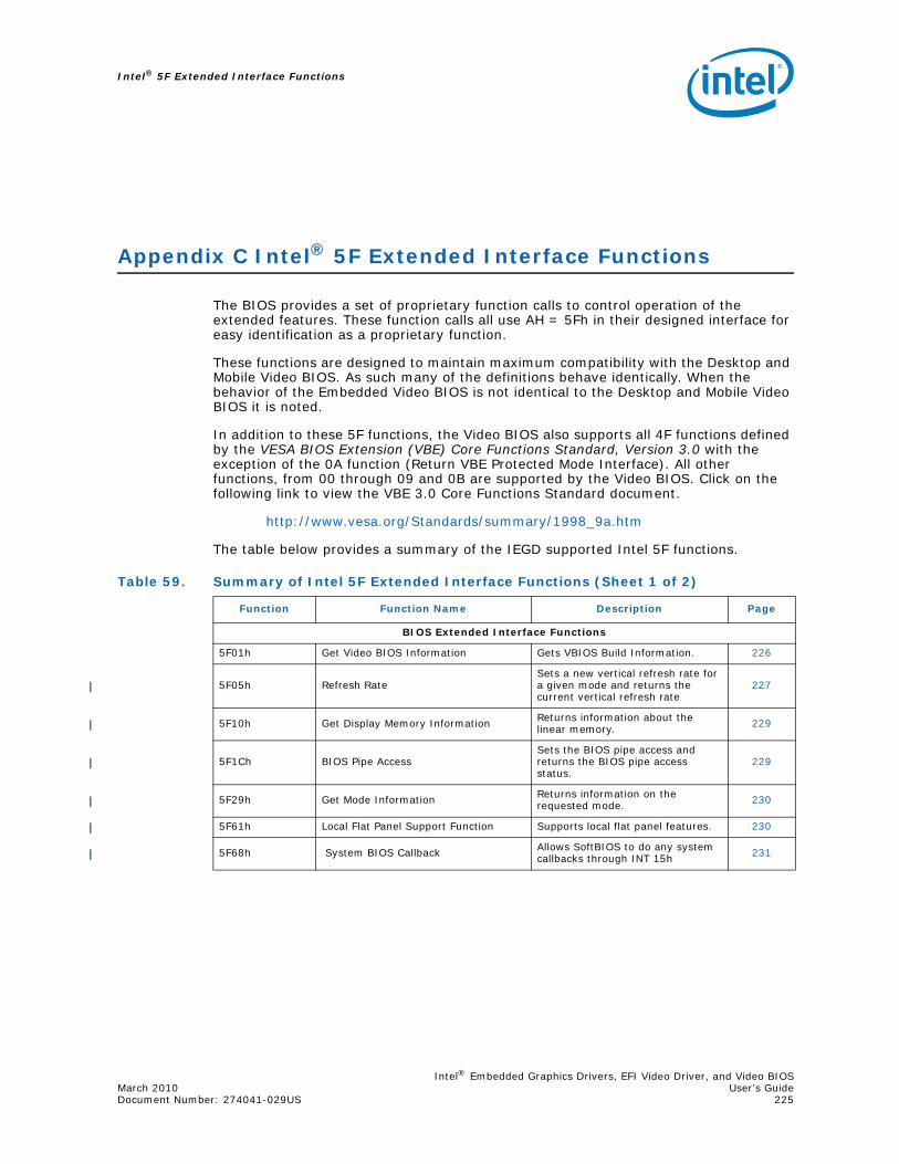
Intel® Embedded Graphics Drivers, EFI Video Driver, and Video BIOSMarch 2010 User’s GuideDocument Number: 274041-029US 225
Intel® 5F Extended Interface Functions
Appendix C Intel® 5F Extended Interface Functions
The BIOS provides a set of proprietary function calls to control operation of the extended features. These function calls all use AH = 5Fh in their designed interface for easy identification as a proprietary function.
These functions are designed to maintain maximum compatibility with the Desktop and Mobile Video BIOS. As such many of the definitions behave identically. When the behavior of the Embedded Video BIOS is not identical to the Desktop and Mobile Video BIOS it is noted.
In addition to these 5F functions, the Video BIOS also supports all 4F functions defined by the VESA BIOS Extension (VBE) Core Functions Standard, Version 3.0 with the exception of the 0A function (Return VBE Protected Mode Interface). All other functions, from 00 through 09 and 0B are supported by the Video BIOS. Click on the following link to view the VBE 3.0 Core Functions Standard document.
http://www.vesa.org/Standards/summary/1998_9a.htm
The table below provides a summary of the IEGD supported Intel 5F functions.
Table 59. Summary of Intel 5F Extended Interface Functions (Sheet 1 of 2)
Function Function Name Description Page
BIOS Extended Interface Functions
5F01h Get Video BIOS Information Gets VBIOS Build Information. 226
5F05h Refresh RateSets a new vertical refresh rate for a given mode and returns the current vertical refresh rate
227
5F10h Get Display Memory Information Returns information about the linear memory. 229
5F1Ch BIOS Pipe AccessSets the BIOS pipe access and returns the BIOS pipe access status.
229
5F29h Get Mode Information Returns information on the requested mode. 230
5F61h Local Flat Panel Support Function Supports local flat panel features. 230
5F68h System BIOS Callback Allows SoftBIOS to do any system callbacks through INT 15h 231

Intel® 5F Extended Interface Functions
Intel® Embedded Graphics Drivers, EFI Video Driver, and Video BIOSUser’s Guide March 2010 226 Document Number: 274041-029US
C.1 BIOS Extended Interface Functions
The BIOS provides a set of proprietary function calls to control operation of the extended features. These function calls all use AH = 5Fh in their designed interface for easy identification as a proprietary function
These functions are designed to maintain maximum compatibility with the Desktop and Mobile Video BIOS. As such many of the definitions behave identically. When the behavior of the Embedded Video BIOS is not identical to the Desktop and Mobile Video BIOS it is noted.
C.1.1 5F01h – Get Video BIOS Information
This function returns the Video BIOS Build information.
Note: This function is an extension of the Desktop and Mobile Video BIOS. If register ECX does not contain ASCII characters “IEGD” then the VBIOS is not described by this specification.
Calling Register:
AX = 5F01h, Get Video Information functionReturn Registers:
AX = Return Status (function not supported if AL != 5Fh):= 005Fh, Function supported and successful= 015Fh, Function supported but failed
EBX = 4 bytes Video BIOS Build Number ASCII string, e.g., ‘1000’ECX = 4 bytes Embedded Identifier, ASCII string ‘IEGD’
Hooks for the System BIOS
5F31h POST Completion Notification Hook Signals the completion of video POST (Power On Self Test) 231
5F33h Hook After Mode SetAllows System BIOS to intercept Video BIOS at the end of a mode set.
231
5F35h Boot Display Device Hook Allows System BIOS to override video display default setting. 232
5F36h Boot TV Format Hook Allows System BIOS to boot TV in selected TV format state. 233
5F38h Hook Before Set ModeAllows System BIOS to intercept Video BIOS before setting the mode.
233
5F40h Config ID HookAllows System BIOS to supply a configuration ID that is passed to the driver.
234
Table 59. Summary of Intel 5F Extended Interface Functions (Sheet 2 of 2)
Function Function Name Description Page

Intel® Embedded Graphics Drivers, EFI Video Driver, and Video BIOSMarch 2010 User’s GuideDocument Number: 274041-029US 227
Intel® 5F Extended Interface Functions
C.1.2 5F05h – Refresh Rate
This function sets a new vertical refresh rate for a given mode and returns the current vertical refresh rate and available refresh rate for a given non-VGA mode.
C.1.2.1 5F05h, 00h – Set Refresh Rate
This sub-function sets a new default refresh rate for the selected pipe. If the mode is currently active, the CRT controller and other registers will be automatically programmed setting the requested refresh rate.
Note: This function is not entirely compatible with the Desktop and Mobile versions. It is not possible to set the refresh rate for a given mode in advance. This function sets the “desired” refresh rate which will be applied to all subsequent mode sets when possible. If the mode provided in BL is the current mode, then a mode change will be automatically performed.
Calling Register:
AX = 5F05h, Refresh Rate functionBH = 00h, Set Refresh Rate sub-functionBL = Mode NumberECX = Refresh rate (indicated by setting one bit):
Bits 31 - 9 = ReservedBit 8 = 120 HzBit 7 = 100 HzBit 6 = 85 HzBit 5 = 75 HzBit 4 = 72 HzBit 3 = 70 Hz Bit 2 = 60 HzBit 1 = 56 HzBit 0 = 43 Hz (Interlaced - Not supported)
Return Registers:
AX = Return Status (function not supported if AL != 5Fh):= 005Fh, Function supported and successful= 015Fh, Function supported but failed

Intel® 5F Extended Interface Functions
Intel® Embedded Graphics Drivers, EFI Video Driver, and Video BIOSUser’s Guide March 2010 228 Document Number: 274041-029US
C.1.2.2 5F05h, 01h – Get Refresh Rate
This sub-function returns current vertical refresh rate for the selected pipe and available refresh rates information for a given Non-VGA mode.
Note: This sub-function returns a status of supported but failed (AX = 015Fh) if executed with a standard VGA mode.
Calling Registers:
AX = 5F05h, Refresh Rate functionBH = 01h, Get Refresh Rate sub-functionBL = Mode number
Return Registers:
AX = Return Status (function not supported if AL != 5Fh):= 005Fh, Function supported and successful= 015Fh, Function supported but failed
EBX = Available refresh rates (indicated by one or more bits set):Bits 31 - 9 = ReservedBit 8 = 120 HzBit 7 = 100 HzBit 6 = 85 HzBit 5 = 75 HzBit 4 = 72 HzBit 3 = 70 Hz Bit 2 = 60 HzBit 1 = 56 HzBit 0 = 43 Hz (Interlaced - Not supported)
ECX = Current refresh rate (see EBX for bit definitions)

Intel® Embedded Graphics Drivers, EFI Video Driver, and Video BIOSMarch 2010 User’s GuideDocument Number: 274041-029US 229
Intel® 5F Extended Interface Functions
C.1.3 5F10h – Get Display Memory Information
This function returns information regarding the linear memory starting address, size and memory mapped base address.
Calling Register:
AX = 5F10h, Get Linear Display Memory Information functionReturn Registers:
AX = Return Status (function not supported if AL != 5Fh):= 005Fh, Function supported and successful= 015Fh, Function supported but failed
ESI = Display memory base addressECX = Total physical display memory size (in bytes)EDX = Available display memory size (in bytes)EDI = Memory Mapped I/O Base AddressEBX = Stride (memory scan line width in bytes)
C.1.4 5F1Ch – BIOS Pipe Access
This function will set the BIOS pipe access or return the BIOS pipe access status.
C.1.4.1 5F1Ch, 00h – Set BIOS Pipe Access
This sub-function will set the currently selected pipe. All 5f functions operate on the currently selected pipe.
When not in clone modes this value cannot be set.
Calling Registers:
AX = 5F1Ch, BIOS Pipe Access functionBH = 00h, Set BIOS Pipe Access sub-functionCH = BIOS Pipe access:
= 00h, Pipe A= 01h, Pipe B
Return Registers:
AX = Return Status (function not supported if AL != 5Fh):= 005Fh, Function supported and successful= 015Fh, Function supported but failed
C.1.4.2 5F1Ch, 01h – Get BIOS Pipe Access
This sub-function will return the currently selected pipe.
Calling Registers:
AX = 5F1Ch, BIOS Pipe Access functionBH = 01h, Get BIOS Pipe Access sub-function
Return Registers:
AX = Return Status (function not supported if AL != 5Fh):= 005Fh, Function supported and successful= 015Fh, Function supported but failed
CH = BIOS Pipe access:= 00h, Pipe A= 01h, Pipe B

Intel® 5F Extended Interface Functions
Intel® Embedded Graphics Drivers, EFI Video Driver, and Video BIOSUser’s Guide March 2010 230 Document Number: 274041-029US
C.1.5 5F29h – Get Mode Information
This function returns the requested mode’s resolution, color depth, and maximum required bandwidth using its current refresh rate. This function is applied to extended-graphics modes only. If the mode number is not an extended graphics mode, the function will return failure.
Calling Registers:
AX = 5F29h, Get Mode Information functionBH = Mode To Use:
= 80h, Current Mode = 00h - 7Fh, Given Mode Number
Return Registers:
AX = Return Status (function not supported if AL != 5Fh):= 005Fh, Function supported and successful= 015Fh, Function supported but failed
EBX bits 31 - 16 = Mode horizontal (X) resolution in pixelsEBX bits 15 - 0 = Mode vertical (Y) resolution in pixelsECX bits 31 - 16 = Maximum bandwidth in megabytes per secondECX bits 15 - 0 = Color depth in bits per pixel
C.1.6 5F61h – Local Flat Panel Support Function
This function supports local flat panel only features.
Note: Only Subfunction 5h of the 5f61h interface is supported for the Embedded vBIOS.
C.1.6.1 5F61h, 05h – Get Configuration ID
This function is used to return the Configuration ID.
Note: This function is known as “Get Local Flat Panel Number” in the Desktop and Mobile Video BIOS. This function performs a similar purpose however, the configuration IDs have no pre-defined meaning. The Configuration ID is reported to the Embedded Graphics Driver and will be used as described in the Intel® Embedded Graphics Drivers and Video BIOS User’s Guide.
Calling Registers:
AX = 5F61h, Local Flat Panel Support functionBH = 05h, Get Config ID Subfunction
Return Registers:
AX = Return Status (function not supported if AL != 5Fh):= 005Fh, Function supported and successful= 015Fh, Function supported but failed
BL = Config ID
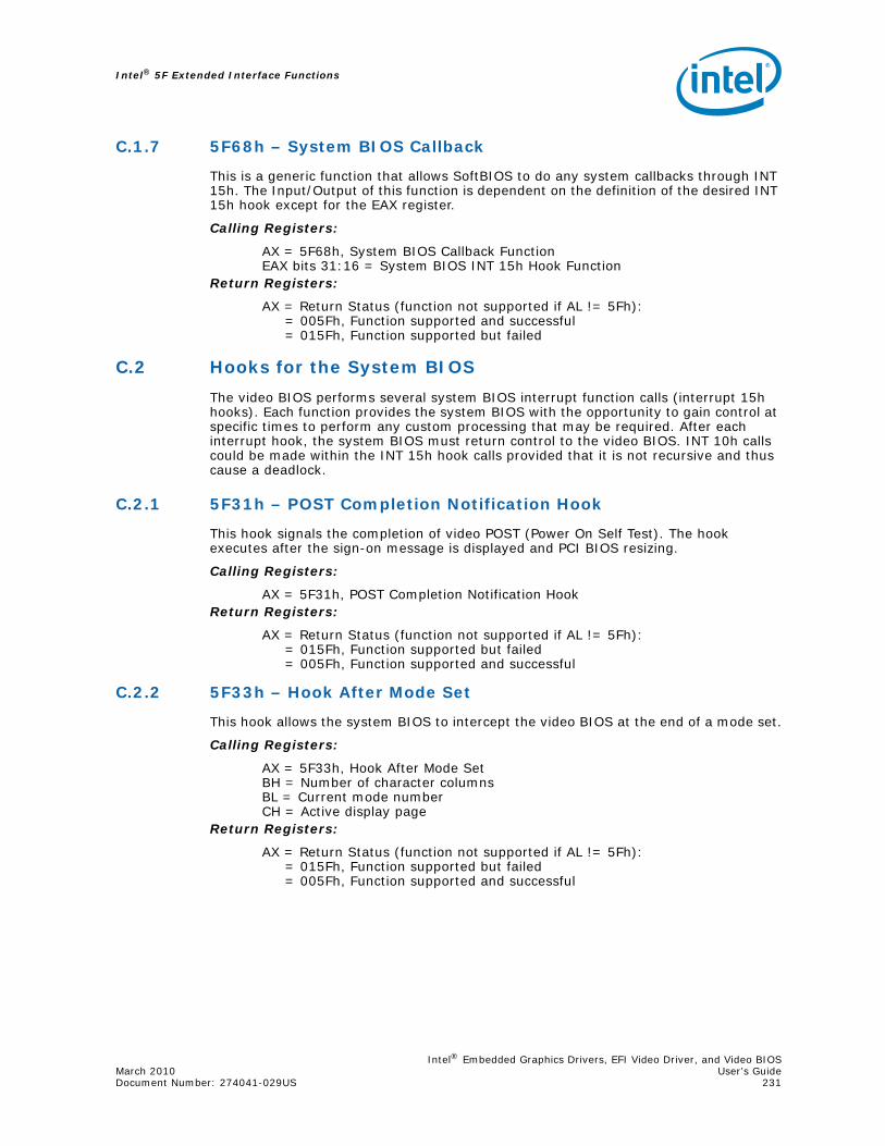
Intel® Embedded Graphics Drivers, EFI Video Driver, and Video BIOSMarch 2010 User’s GuideDocument Number: 274041-029US 231
Intel® 5F Extended Interface Functions
C.1.7 5F68h – System BIOS Callback
This is a generic function that allows SoftBIOS to do any system callbacks through INT 15h. The Input/Output of this function is dependent on the definition of the desired INT 15h hook except for the EAX register.
Calling Registers:
AX = 5F68h, System BIOS Callback FunctionEAX bits 31:16 = System BIOS INT 15h Hook Function
Return Registers:
AX = Return Status (function not supported if AL != 5Fh):= 005Fh, Function supported and successful= 015Fh, Function supported but failed
C.2 Hooks for the System BIOS
The video BIOS performs several system BIOS interrupt function calls (interrupt 15h hooks). Each function provides the system BIOS with the opportunity to gain control at specific times to perform any custom processing that may be required. After each interrupt hook, the system BIOS must return control to the video BIOS. INT 10h calls could be made within the INT 15h hook calls provided that it is not recursive and thus cause a deadlock.
C.2.1 5F31h – POST Completion Notification Hook
This hook signals the completion of video POST (Power On Self Test). The hook executes after the sign-on message is displayed and PCI BIOS resizing.
Calling Registers:
AX = 5F31h, POST Completion Notification HookReturn Registers:
AX = Return Status (function not supported if AL != 5Fh):= 015Fh, Function supported but failed= 005Fh, Function supported and successful
C.2.2 5F33h – Hook After Mode Set
This hook allows the system BIOS to intercept the video BIOS at the end of a mode set.
Calling Registers:
AX = 5F33h, Hook After Mode SetBH = Number of character columnsBL = Current mode numberCH = Active display page
Return Registers:
AX = Return Status (function not supported if AL != 5Fh):= 015Fh, Function supported but failed= 005Fh, Function supported and successful

Intel® 5F Extended Interface Functions
Intel® Embedded Graphics Drivers, EFI Video Driver, and Video BIOSUser’s Guide March 2010 232 Document Number: 274041-029US
C.2.3 5F35h – Boot Display Device Hook
This hook allows the system BIOS to override the video display default setting. The graphics BIOS will set the returned video display during POST (power up initialization).
Note: This function is not entirely compatible with the Desktop and Mobile Video BIOS. The bits in CL have a configurable mapping to the Port Numbers as defined in the Intel® Embedded Graphics Drivers and Video BIOS User’s Guide. The assigned meanings used in the Desktop specification can be duplicated with a correct configuration. The values below are the default values if no “Common To Port” mapping is provided.
Calling Registers:
AX = 5F35h, Boot Display Device HookReturn Registers:
AX = Return Status (function not supported if AL != 5Fh);= 005Fh, Function supported and successful = 015Fh, Function supported but failed
CL = Display Device Combination to boot (1 = Enable display, 0 = Disable display):
= 00h, VBIOS DefaultBit 7 - 6 = ReservedBit 5 = Port 5 (or common_to_port[5])Bit 4 = Port 4 (or common_to_port[4])Bit 3 = Port 3 (or common_to_port[3])Bit 2 = Port 2 (or common_to_port[2])Bit 1 = Port 1 (or common_to_port[1])Bit 0 = Port 0 (or common_to_port[0])

Intel® Embedded Graphics Drivers, EFI Video Driver, and Video BIOSMarch 2010 User’s GuideDocument Number: 274041-029US 233
Intel® 5F Extended Interface Functions
C.2.4 5F36h – Boot TV Format Hook
This hook allows the system BIOS to boot TV in selected TV format state.
Calling Registers:
AX = 5F36h, Boot TV Format HookReturn Registers:
AX = Return Status (function not supported if AL != 5Fh):= 015Fh, Function supported but failed= 005Fh, Function supported and successful
BL = TV Format requested:= 00h, No Preference= 01h, NTSC_M= 11h, NTSC_M_J= 21h, NTSC_433= 31h, NTSC_N= 02h, PAL_B= 12h, PAL_G= 22h, PAL_D= 32h, PAL_H= 42h, PAL_I= 52h, PAL_M= 62h, PAL_N= 72h, PAL_60= 03h, SECAM_L= 13h, SECAM_L1= 23h, SECAM_B= 33h, SECAM_D= 43h, SECAM_G= 53h, SECAM_H= 63h, SECAM_K= 73h, SECAM_K1
C.2.5 5F38h – Hook Before Set Mode
This hook allows the system BIOS to intercept the video BIOS before setting the mode.
Calling Registers:
AX = 5F38h, Hook Before Set ModeCL = New video mode to be set
Return Registers:
AX = Return Status (function not supported if AL != 5Fh):= 015Fh, Function supported but failed= 005Fh, Function supported and successful

Intel® 5F Extended Interface Functions
Intel® Embedded Graphics Drivers, EFI Video Driver, and Video BIOSUser’s Guide March 2010 234 Document Number: 274041-029US
C.2.6 5F40h – Config ID Hook
This function is known as “Boot Panel Type Hook” in the Desktop and Mobile Video BIOS. It allows the system BIOS to supply a configuration ID that will eventually be passed to the driver. This configuration ID is unused by the Video BIOS; however, it alters the behavior of the driver as described in the Intel® Embedded Graphics Drivers and Video BIOS User’s Guide.
Calling Registers:
AX = 5F40h, Config ID HookReturn Registers:
AX = Return Status (function not supported if AL != 5Fh):= 005Fh, Function supported and successful= 015Fh, Function supported but failed
CL = Configuration ID

Intel® Embedded Graphics Drivers, EFI Video Driver, and Video BIOSMarch 2010 User’s GuideDocument Number: 274041-029US 235
2D/3D API Support
Appendix D 2D/3D API Support
This appendix provides information on supported and non-supported OpenGL and OpenGL ES APIs. See Section 7.6.10, “OpenGL Support” on page 196 for additional information.
D.1 2D Support
IEGD provides 2D capabilities on Linux through UXA and on Windows through DirectX/GDI.
D.2 3D Support
IEGD provides 3D capabilities on Linux, Windows, and Windows CE through several industry-standard APIs, such as OpenGL, OpenGL ES, Direct3D, and D3DMobile. These APIs are described in the following sections.
D.2.1 OpenGL APIs
The following OpenGL versions are supported:
• Version 1.3 on all Embedded Intel® Architecture (eIA) chipsets (Linux only)
• Version 1.4 on 915GV, 915GM, 945G, 945GM, Q965, GLE960/GME965 (Linux only) and Intel® Atom™ Processor 400 and 500 Series
• Version 1.5 on Q965, GLE960/GME965, Q45/G41/G45, GM45/GL40/GS45, and Q35 (Linux only)
• Version 2.0 on US15W/US15WP/WPT (Linux and Windows), Q35, Q45 and GM45 (Linux only)
For general OpenGL information, visit http://www.opengl.org/about/overview/.
Table 60. Supported Intel® OpenGL APIs (Sheet 1 of 2)
Supported API Name(s)
GL_3DFX_texture_compression_FXT1*
GL_ARB_depth_texture
GL_ARB_fragment_program (965 or later only)
GL_ARB_multitexture
GL_ARB_occlusion_query (965 or later only)
GL_ARB_point_sprite
GL_ARB_shadow
GL_ARB_texture_env_dot3
GL_ARB_texture_border_clamp
*Not supported on Intel US15W series chipsets.
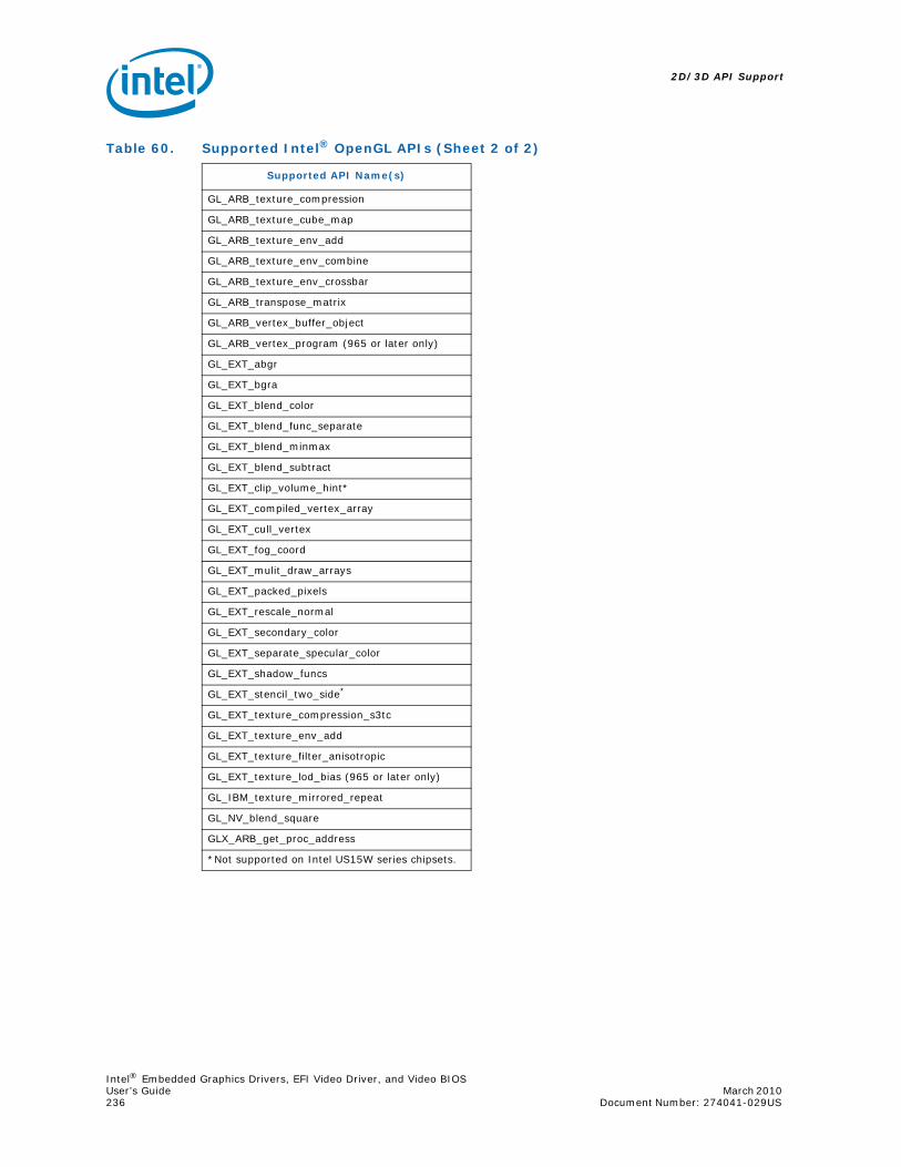
2D/3D API Support
Intel® Embedded Graphics Drivers, EFI Video Driver, and Video BIOSUser’s Guide March 2010 236 Document Number: 274041-029US
GL_ARB_texture_compression
GL_ARB_texture_cube_map
GL_ARB_texture_env_add
GL_ARB_texture_env_combine
GL_ARB_texture_env_crossbar
GL_ARB_transpose_matrix
GL_ARB_vertex_buffer_object
GL_ARB_vertex_program (965 or later only)
GL_EXT_abgr
GL_EXT_bgra
GL_EXT_blend_color
GL_EXT_blend_func_separate
GL_EXT_blend_minmax
GL_EXT_blend_subtract
GL_EXT_clip_volume_hint*
GL_EXT_compiled_vertex_array
GL_EXT_cull_vertex
GL_EXT_fog_coord
GL_EXT_mulit_draw_arrays
GL_EXT_packed_pixels
GL_EXT_rescale_normal
GL_EXT_secondary_color
GL_EXT_separate_specular_color
GL_EXT_shadow_funcs
GL_EXT_stencil_two_side*
GL_EXT_texture_compression_s3tc
GL_EXT_texture_env_add
GL_EXT_texture_filter_anisotropic
GL_EXT_texture_lod_bias (965 or later only)
GL_IBM_texture_mirrored_repeat
GL_NV_blend_square
GLX_ARB_get_proc_address
Table 60. Supported Intel® OpenGL APIs (Sheet 2 of 2)
Supported API Name(s)
*Not supported on Intel US15W series chipsets.
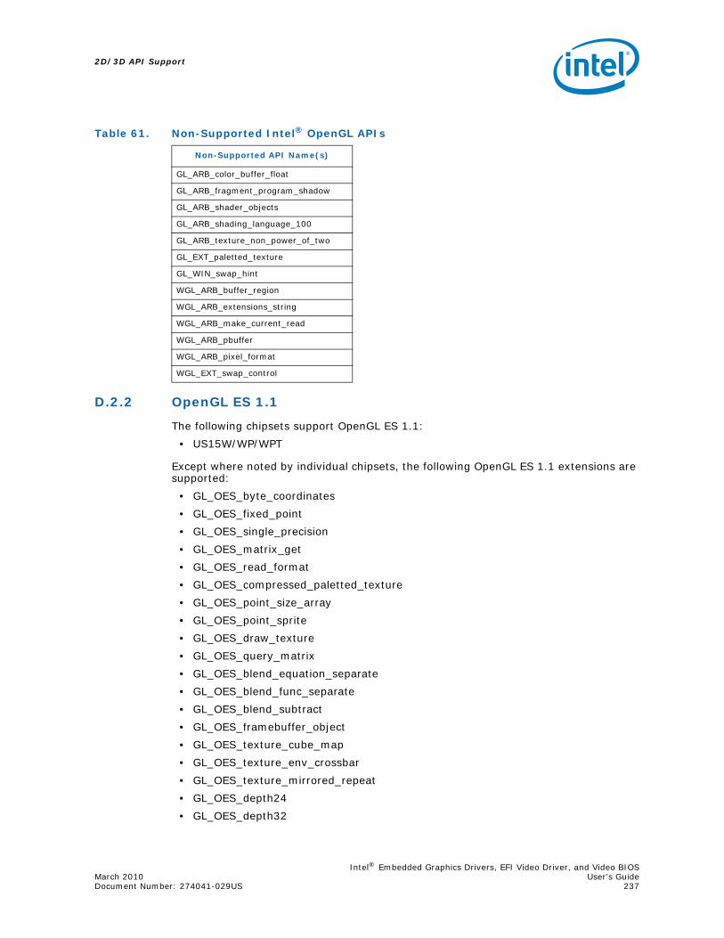
Intel® Embedded Graphics Drivers, EFI Video Driver, and Video BIOSMarch 2010 User’s GuideDocument Number: 274041-029US 237
2D/3D API Support
D.2.2 OpenGL ES 1.1
The following chipsets support OpenGL ES 1.1:
• US15W/WP/WPT
Except where noted by individual chipsets, the following OpenGL ES 1.1 extensions are supported:
• GL_OES_byte_coordinates
• GL_OES_fixed_point
• GL_OES_single_precision
• GL_OES_matrix_get
• GL_OES_read_format
• GL_OES_compressed_paletted_texture
• GL_OES_point_size_array
• GL_OES_point_sprite
• GL_OES_draw_texture
• GL_OES_query_matrix
• GL_OES_blend_equation_separate
• GL_OES_blend_func_separate
• GL_OES_blend_subtract
• GL_OES_framebuffer_object
• GL_OES_texture_cube_map
• GL_OES_texture_env_crossbar
• GL_OES_texture_mirrored_repeat
• GL_OES_depth24
• GL_OES_depth32
Table 61. Non-Supported Intel® OpenGL APIs
Non-Supported API Name(s)
GL_ARB_color_buffer_float
GL_ARB_fragment_program_shadow
GL_ARB_shader_objects
GL_ARB_shading_language_100
GL_ARB_texture_non_power_of_two
GL_EXT_paletted_texture
GL_WIN_swap_hint
WGL_ARB_buffer_region
WGL_ARB_extensions_string
WGL_ARB_make_current_read
WGL_ARB_pbuffer
WGL_ARB_pixel_format
WGL_EXT_swap_control

2D/3D API Support
Intel® Embedded Graphics Drivers, EFI Video Driver, and Video BIOSUser’s Guide March 2010 238 Document Number: 274041-029US
• GL_OES_element_index_uint
• GL_OES_fbo_render_mipmap
• GL_OES_mapbuffer
• GL_OES_rgb8_rgba8
• GL_OES_stencil1
• GL_OES_stencil4
• GL_OES_stencil8
• GL_EXT_texture_filter_anisotropic
D.2.3 OpenGL ES 2.0
The following chipsets support OpenGL ES 2.0:
• US15W/WP/WPT
Except where noted by individual chipsets, the following OpenGL ES 2.0 extensions are supported:
• GL_OES_single_precision
• GL_OES_compressed_paletted_texture
• GL_OES_depth24
• GL_OES_depth32
• GL_OES_element_index_uint
• GL_OES_fbo_render_mipmap
• GL_OES_mapbuffer
• GL_OES_rgb8_rgba8
• GL_OES_stencil1
• GL_OES_stencil4
• GL_OES_texture_3D
• GL_OES_texture_npot
• GL_EXT_texture_filter_anisotropic
• GL_EXT_texture_type_2_10_10_10_REV
• GL_OES_depth_texture
• GL_OES_standard_derivatives

Intel® Embedded Graphics Drivers, EFI Video Driver, and Video BIOSMarch 2010 User’s GuideDocument Number: 274041-029US 239
2D/3D API Support
Table 62. Non-Supported Intel® OpenGL ES APIs on US15W/WP/WPT
Non-Supported API Name(s)
GL_OES_stencil_wrap
GL_OES_compressed_ETC1_RGB8_texture
GL_OES_matrix_palette
GL_OES_EGL_image
GL_AMD_compressed_3DC_texture
GL_AMD_compressed_ATC_texture
GL_OES_texture_float
GL_OES_texture_half_float
GL_OES_texture_float_linear
GL_OES_texture_half_float_linear
GL_OES_vertex_half_float
GL_OES_vertex_type_10_10_10_2
GL_OES_fragment_precision_high

This page is intentionally left blank.
2D/3D API Support
Intel® Embedded Graphics Drivers, EFI Video Driver, and Video BIOSUser’s Guide March 2010 240 Document Number: 274041-029US

Intel® Embedded Graphics Drivers, EFI Video Driver, and Video BIOSMarch 2010 User’s GuideDocument Number: 274041-029US 241
Framebuffer Overlay Blending
Appendix E Framebuffer Overlay Blending
This appendix describes behavior of the IEGD Framebuffer Overlay Blending (FB_BLEND_OVL) feature.
E.1 How Overlay Works
The overlay is visible as if “on top” of the frame buffer, appearing only where the color key matches.
The overlay plane is actually behind the display plane (last in Z-order). The framebuffer overrides all overlay pixels in the pipe except where the color key matches.
Display Plane
Color KeyOverlay Plane
DisplayON TOP
Color Key
OverlayON BOTTOM

Framebuffer Overlay Blending
Intel® Embedded Graphics Drivers, EFI Video Driver, and Video BIOSUser’s Guide March 2010 242 Document Number: 274041-029US
E.2 About Framebuffer in “Blend” Mode
IEGD has always expressed the mode setting operation as Width X Height at 8, 16, or 32 bpp. In all bit depths, IEGD does not expose any mode with an alpha channel (i.e., 32 bpp = X8R8G8B8, not A8R8G8B8).
However, the hardware does support 32 bpp with alpha (== A8R8G8B8).
How is this used? The Display Plane in ARGB32 contains per-pixel Alpha to be blended with all other planes on the same display pipeline. This “Alpha” data is dictated by the application.
If all the Alpha channel (8 MSbits) for Display A and Cursor A were zero (0x00), this means those two planes are completely transparent.
If all the Alpha channel (8 MSbits) for Display A and Cursor A were max (0xFF) – this means it is completely opaque.
Cursor A
Display A
Overlay
HWPipe
BlenderOverlay
Display ACursorA
Display Port
Display A
Overlay
HWPipe
Blender
Display Port
Only Overlaypixels are displayed
Cursor A
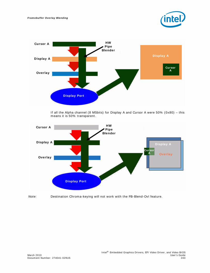
Intel® Embedded Graphics Drivers, EFI Video Driver, and Video BIOSMarch 2010 User’s GuideDocument Number: 274041-029US 243
Framebuffer Overlay Blending
If all the Alpha channel (8 MSbits) for Display A and Cursor A were 50% (0x80) – this means it is 50% transparent.
Note: Destination Chroma-keying will not work with the FB-Blend-Ovl feature.
CursorA
Display A
Cursor A
Overlay
HWPipe
Blender
Display Port
Display A
CursorA
Display A
OverlayOverlay
Display A
Cursor A HWPipe
Blender
Display Port
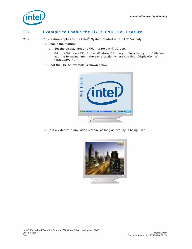
Framebuffer Overlay Blending
Intel® Embedded Graphics Drivers, EFI Video Driver, and Video BIOSUser’s Guide March 2010 244 Document Number: 274041-029US
E.3 Example to Enable the FB_BLEND_OVL Feature
Note: This feature applies to the Intel® System Controller Hub US15W only.
1. Enable the feature:
a. Set the display mode to Width x Height @ 32 bpp.
b. Edit the Windows XP .inf or Windows CE .reg or Linux Xorg.conf file and add the following line in the same section where you find “DisplayConfig”: “FbBlendOvl” = 1
2. Boot the OS. An example is shown below.
3. Run a video with any video stream, as long as overlay is being used.

Intel® Embedded Graphics Drivers, EFI Video Driver, and Video BIOSMarch 2010 User’s GuideDocument Number: 274041-029US 245
Framebuffer Overlay Blending
4. Run a D3D/OGL application. Ensure that the application has been modified so that the render target has valid alpha. Use an alpha value such as 0.5 (0x80 = 50% transparency).
E.4 Summary
You must use a 3D API to get the application on the framebuffer with a valid alpha value to blend on top of the video overlay. 2D API is not supported.
If the application has an alpha value of 0.0 or 1.0, it is either semi-transparent or fully opaque – which is useless because color keying can give you the same effect.
On any operating system you can use OS APIs that already exist to directly write alpha data to the framebuffer if you want.
The 3D output appears on the display, carries a 50% transparency, and is blended with the overlay. The overlay is behind and 3D output is on top – on the display plane.

This page is intentionally left blank.
Framebuffer Overlay Blending
Intel® Embedded Graphics Drivers, EFI Video Driver, and Video BIOSUser’s Guide March 2010 246 Document Number: 274041-029US