integration of ultra capacitor with battery using dc … of ultra capacitor with battery using dc-dc...
TRANSCRIPT
International Research Journal of Engineering and Technology (IRJET) e-ISSN: 2395 -0056
Volume: 03 Issue: 02 | Feb-2016 www.irjet.net p-ISSN: 2395-0072
© 2016, IRJET | Impact Factor value: 4.45 | ISO 9001:2008 Certified Journal | Page 1513
Integration of Ultra Capacitor with Battery using DC-DC Bidirectional
Buck Boost Converter in an Electric Vehicle.
Mohammad Ashar
Mtech Student, Dept. of Electrical Engineering, G.H.R.C.E., Maharashtra, India.
---------------------------------------------------------------------***---------------------------------------------------------------------Abstract - Hybrid energy storage system of electric vehicles
(EVs) has great potential to take full advantages of high
power density with super-capacitor and high energy density
with battery to improve the dynamic performance and energy
efficiency of EVs. In this paper, a Super/ Ultra Capacitor is
integrated with the battery in an Electric Vehicle using a Buck-
Boost Converter to improve the dynamic performance of the
vehicle system and enhancing the battery life. A computer
based simulation was carried out in Matlab Simulink
environment.
Key Words: Electric Vehicles (EVs), Ultra Capacitor,
DC-DC Converter, Regenerative Braking, PWM
Controller.
1.INTRODUCTION The Hybridization of electric vehicle (EV) with other sources of power is the recent advancement in the field of research and development to develop challenging technologies for electric vehicles in order to beat over the traditional combustion engine vehicles due to the fact that the natural reserves are depleting and also these conventional vehicles are a threat to the environment because of its emissions. In order to promote the manufacturing, use of electric vehicles, and to increase its market share, the Government of India has framed policies, schemes of exempting taxes and registrations to boost this Electric Vehicle Segment.
Hence, many ways are explored to make the electric vehicles more efficient with integration of other sources of power such solar panels, fuel cells, ultra-capacitors etc. with the base power supply. With hybridization, the electric vehicles have the better acceleration capability during high power demands and an efficient recovery of energy during regenerative braking periods.
With this paper, a battery powered electric vehicle hybridized with ultra-capacitor is presented. Ultra Capacitors are recently developed high farad capacitors capable of receiving and delivering a high amount of power almost instantaneously. They have a high power density but low energy density. Whereas, batteries have a higher energy density but low power density as it undergoes chemical
reaction while charge/discharge cycles and hence takes its processing time for its operation.
The Load profiles of an electric vehicle is not uniform but is repetitive with high peaks and steep valleys. Hence, repetitive acceleration and deceleration occurs during its operation which is transient in nature. As the battery is incapable of delivering/receiving a high power for a short period of time, the vehicle system with only battery as a source has the reduced performance. If battery is hybridized with ultra-capacitor with a DC-DC converter, the ultra-capacitor with take care of the above mentioned transient operating conditions due to its peculiar characteristics and will save the battery from such high power situations. This will increase the life of the battery which thereby will reduce the maintenance cost of the vehicle(Battery replacement). It will also improve the vehicle performance during higher acceleration and deceleration and provide a better voltage regulation in the system.
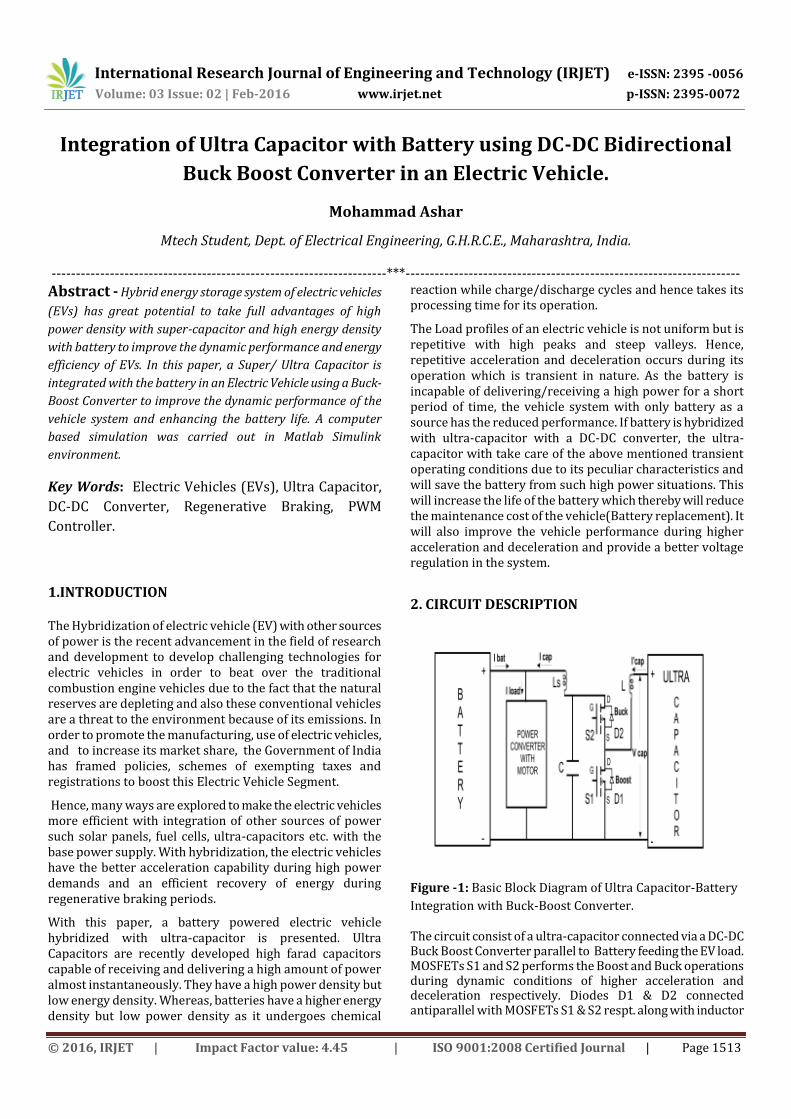
2. CIRCUIT DESCRIPTION
Figure -1: Basic Block Diagram of Ultra Capacitor-Battery
Integration with Buck-Boost Converter.
The circuit consist of a ultra-capacitor connected via a DC-DC Buck Boost Converter parallel to Battery feeding the EV load. MOSFETs S1 and S2 performs the Boost and Buck operations during dynamic conditions of higher acceleration and deceleration respectively. Diodes D1 & D2 connected antiparallel with MOSFETs S1 & S2 respt. along with inductor

International Research Journal of Engineering and Technology (IRJET) e-ISSN: 2395 -0056
Volume: 03 Issue: 02 | Feb-2016 www.irjet.net p-ISSN: 2395-0072
© 2016, IRJET | Impact Factor value: 4.45 | ISO 9001:2008 Certified Journal | Page 1514
L helps perform the desired operation. Capacitor C maintains the DC voltage level at the output of the Converter while Inductor Ls acts as a smoothing reactor for the converter current(Icap).
In dynamic conditions i.e. during higher acceleration or deceleration periods, the Ultra Capacitor will act as the charging and discharging device due to its ability to act fast and while in normal working mode the battery will supply the load making the system optimized. The direction of the power flow while acceleration and deceleration is shown in the figure2 and 3 respectively.
Figure -2: Power Flow During Acclivity.
Figure -3: Power Flow During Acclivity.
During Boost operation (Higher Acceleration), MOSFET S1 switches ON/OFF as per controller duty cycle and S2 is maintained in OFF state. When S1 is turned ON, the Ultra Capacitor energy is stored in the Inductor(L) and emf is generated in the coil. When S1 is turned OFF, the stored inductor energy is transferred to the Load through Diode D2 as the Voltage at the Ultra-capacitor side is more than the Load side.
During Buck operation (Higher Deceleration), MOSFET S2 switches ON/OFF as per controller Duty Cycle and S1 is maintained in OFF state. When S2 is turned ON, the Energy is stored in the Inductor (L) and when S2 is turned OFF, the stored energy is transferred to the Ultra-Capacitor through
the freewheeling diode D1. This is also called as the regenerative braking condition where the power is transferred from load to the source.
3. CONTROL STRATEGY The instantaneous values of Load Voltage, Load Current,
Capacitor Voltage, Capacitor Current and Battery voltage is
sensed and accordingly controlled PWM signals are
generated for the Buck- Boost operation.
When the vehicle accelerates, the battery supplies the current
required by the motor, if the supplied current exceeds the
nominal current rating of battery(Pre-established Current
Limit), then the Ultra-Capacitor will make up the difference in
current with the Boost operation of the converter, limiting
the current supplied by battery to its nominal value.
Similarly, in regenerative braking, the motor acts as a source
and transfer the recovered energy to the battery. If the
regenerative current exceeds the pre-established current
limit, the DC-DC converter will work in Buck operation mode
and inject the excess power into the ultra-capacitor.
The controlling strategy applied for the DC-DC Buck-Boost
Converter is divided into two stages: 1.Primary Controller &
2. Secondary Controller.
3.1 Primary Controller
Figure -4: Block Diagram of Primary Controller.
The primary controller senses the instantaneous motor
power and battery voltage. It outputs the difference in power
(Load Power – (Bty voltage x Set Current Limit) ) as shown in
fig.4 followed by the logic, which generates Output power
command for the Ultra-Capacitor only when instantaneous
value of Load Current exceeds the (+ve or -ve) Set Limit
value. This output command serves the input to the
secondary controller.

International Research Journal of Engineering and Technology (IRJET) e-ISSN: 2395 -0056
Volume: 03 Issue: 02 | Feb-2016 www.irjet.net p-ISSN: 2395-0072
© 2016, IRJET | Impact Factor value: 4.45 | ISO 9001:2008 Certified Journal | Page 1515
3.2 Secondary Controller
Figure -5: Circuit Diagram of Secondary Controller with Bi
Directional DC-DC Converter.
The secondary controller generates the Current reference
signal (I_command) from the Power Command generated by
the primary controller as shown in fig.5,compares it with the
instantaneous capacitor current generating an error signal.
This error signal is passed through PI Gain Block and further
through limiter generating a PWM reference input. The PWM
reference input is compared with the sawtooth
waveform(Carrier PWM Signal) of fixed frequency. If the
reference signal is greater that the sawtooth signal(Carrier
PWM Signal) then the PWM pulses are generated for the
Mosfets to perform the desired Buck-Boost operation.
4. SIMULATION
Figure -6: Matlab Simulink Model of Super Capacitor
Integration with Battery using DC-DC Buck-Boost Converter
Feeding Chopper-DC motor Drive.
A Matlab based model is developed and its simulation is
carried out in MATLAB R2013a version. Lead Acid Battery of
Nominal Voltage 220V, Nominal Current 6A, 30AH is used as
a base power source with 80% Initial State of Charge (SOC). A
Super Capacitor of 15 Farad, Rated Voltage 48V is connected
across battery with a DC-DC Buck boost Converter. A Matlab
inbuilt two quadrant chopper DC drive of rating 5 HP, 240V
is used as a load for Electric Vehicle. The Simulation is carried
out for higher acceleration and deceleration periods and the
performance of the system is analysed with the proposed
Buck Boost converter.
The simulation was carried out under:
TRANSIENT OPERATION:
a) Accelerating Mode :Speed Increase from 0km/hr to
60km/hr,Initial Load Torque=20N-m, Load change from
Torque= 20N-m to Torque= 7N-m @step time Of 4.2sec.
b) Decelerating Mode :Speed Decrease from 60km/hr to
20km/hr @ Step time of 8sec , Load change from
Torque= 7N-m toTorque= -20N-m at time Instant of 8 sec.
Total Simulation Time:16sec.
5. ASSUMPTIONS AND SIMULATION PARAMETERS
1. DC-DC Buck Boost Converter is assumed to be lossless.
2. Battery internal resistance does not change with the
amplitude of current. Temperature impact on performance is
neglected.
3. Motor Chopper converter is modelled as an average value
controller.
4. Wheel diameter is assumed to be 0.3 mtr and initial speed
of motor to be 0 Km/hr.
Battery Parameters Type Lead Acid
Vnominal 220V
Rated AH 30AH
Initial SOC 80%
Inominal 6A

International Research Journal of Engineering and Technology (IRJET) e-ISSN: 2395 -0056
Volume: 03 Issue: 02 | Feb-2016 www.irjet.net p-ISSN: 2395-0072
© 2016, IRJET | Impact Factor value: 4.45 | ISO 9001:2008 Certified Journal | Page 1516
DC MOTOR Parameters Rating 5 HP
Vrated 240V
Rated Speed 1750 RPM
Armature Resistance 0.78 ohm
Armature Inductance 16mH
Field Resistance 150 ohm
Field Inductance 112.5 H
Field DC Voltage 150V
Inertia 0.05 Kg-m2
Viscous Friction Coeff. 0.01 N-m-s
Ultra Capacitor Parameters Rated Voltage 48V
Rated Farad 15F
Initial Voltage 46V
6. SIMULATION RESULTS
Graph -1: Waveforms of Battery Current, SC Current &
Motor Current during TRANSIENT OPERATION.
Graph -2: Individual Waveforms of Battery Current, SC
Current & Motor Current during TRANSIENT OPERATION.
Graph -3: Waveform of Load Power during TRANSIENT
OPERATION.
International Research Journal of Engineering and Technology (IRJET) e-ISSN: 2395 -0056
Volume: 03 Issue: 02 | Feb-2016 www.irjet.net p-ISSN: 2395-0072
© 2016, IRJET | Impact Factor value: 4.45 | ISO 9001:2008 Certified Journal | Page 1517
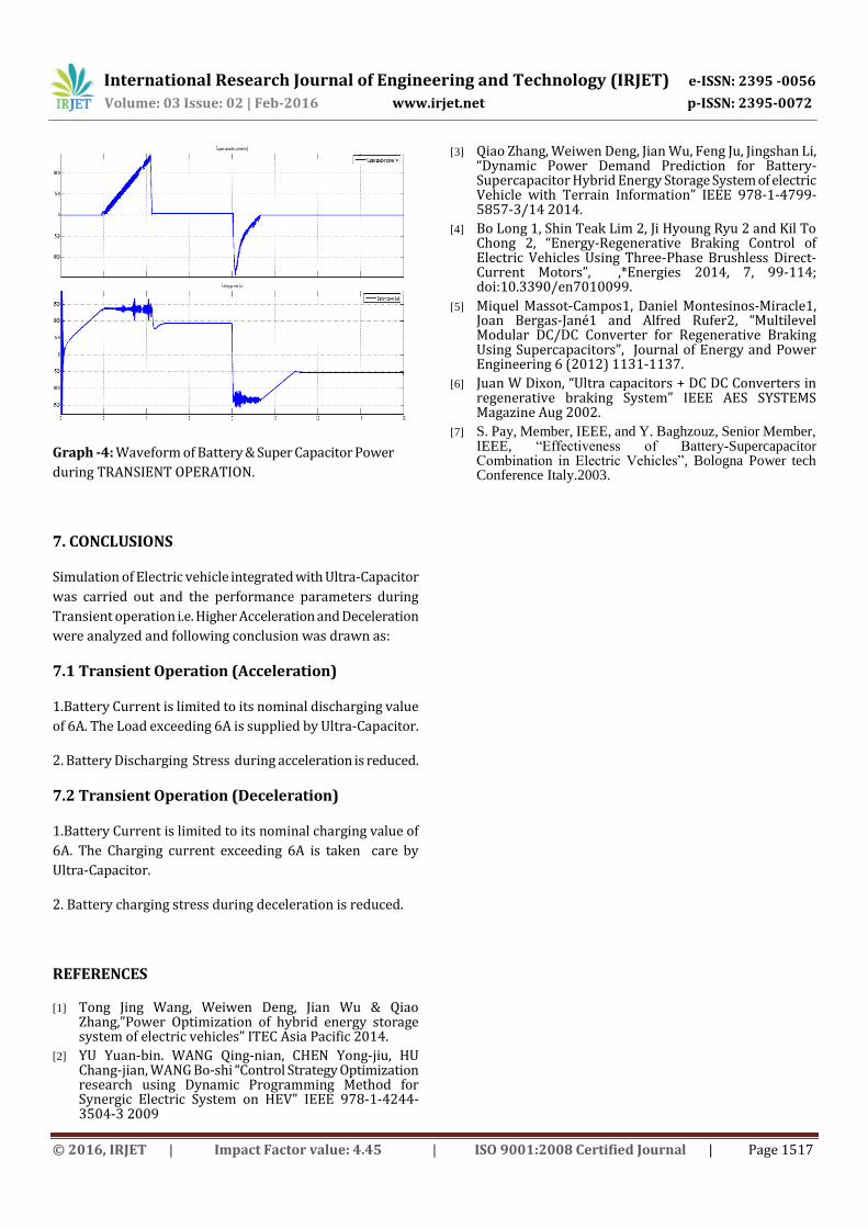
Graph -4: Waveform of Battery & Super Capacitor Power
during TRANSIENT OPERATION.
7. CONCLUSIONS
Simulation of Electric vehicle integrated with Ultra-Capacitor
was carried out and the performance parameters during
Transient operation i.e. Higher Acceleration and Deceleration
were analyzed and following conclusion was drawn as:
7.1 Transient Operation (Acceleration)
1.Battery Current is limited to its nominal discharging value
of 6A. The Load exceeding 6A is supplied by Ultra-Capacitor.
2. Battery Discharging Stress during acceleration is reduced.
7.2 Transient Operation (Deceleration)
1.Battery Current is limited to its nominal charging value of
6A. The Charging current exceeding 6A is taken care by
Ultra-Capacitor.
2. Battery charging stress during deceleration is reduced.
REFERENCES
[1] Tong Jing Wang, Weiwen Deng, Jian Wu & Qiao Zhang,”Power Optimization of hybrid energy storage system of electric vehicles” ITEC Asia Pacific 2014.
[2] YU Yuan-bin. WANG Qing-nian, CHEN Yong-jiu, HU Chang-jian, WANG Bo-shi “Control Strategy Optimization research using Dynamic Programming Method for Synergic Electric System on HEV” IEEE 978-1-4244-3504-3 2009
[3] Qiao Zhang, Weiwen Deng, Jian Wu, Feng Ju, Jingshan Li, “Dynamic Power Demand Prediction for Battery-Supercapacitor Hybrid Energy Storage System of electric Vehicle with Terrain Information” IEEE 978-1-4799-5857-3/14 2014.
[4] Bo Long 1, Shin Teak Lim 2, Ji Hyoung Ryu 2 and Kil To Chong 2, “Energy-Regenerative Braking Control of Electric Vehicles Using Three-Phase Brushless Direct-Current Motors”, ,*Energies 2014, 7, 99-114; doi:10.3390/en7010099.
[5] Miquel Massot-Campos1, Daniel Montesinos-Miracle1, Joan Bergas-Jané1 and Alfred Rufer2, “Multilevel Modular DC/DC Converter for Regenerative Braking Using Supercapacitors”, Journal of Energy and Power Engineering 6 (2012) 1131-1137.
[6] Juan W Dixon, “Ultra capacitors + DC DC Converters in regenerative braking System” IEEE AES SYSTEMS Magazine Aug 2002.
[7] S. Pay, Member, IEEE, and Y. Baghzouz, Senior Member, IEEE, “Effectiveness of Battery-Supercapacitor Combination in Electric Vehicles”, Bologna Power tech Conference Italy.2003.